Article

Optimization Design Method for IGCT Gate Pole Drive Based on Improved Grey Wolf Algorithm
Electric Power Science Research Institute, State Grid Jiangsu Electric Power Co., Ltd., Nanjing 210008, China
*
Author to whom correspondence should be addressed.
Energies 2026, 19(8), 1958; https://doi.org/10.3390/en19081958
Submission received: 2 March 2026 / Revised: 1 April 2026 / Accepted: 15 April 2026 / Published: 18 April 2026

Abstract

Integrated Gate-Commutated Thyristor (IGCT) serves as the core power electronic device in high-voltage and high-power renewable energy conversion systems. Aiming at the problems of slow convergence, easy to fall into local optima, and difficulty in balancing multi-objective performance in traditional IGCT gate drive design under power fluctuation conditions, this paper proposes an IGCT gate drive optimization method based on the Improved Grey Wolf Optimization (IGWO) algorithm. A multi-objective optimization model is established with switching loss reduction, voltage overshoot suppression, current oscillation attenuation and driving capability guarantee as objectives and gate resistance and driving voltage as optimization variables. The traditional grey wolf algorithm is improved by adaptive weight adjustment and dynamic search step strategies to balance global exploration and local exploitation. Simulation and experimental results show that, compared with the traditional Grey Wolf Algorithm (GWO) and Particle Swarm Optimization (PSO), the convergence speed of IGWO is increased by 40.4% and 51.0%, and the optimization accuracy is improved by 12.7% and 18.1%, respectively. Compared with the conventional empirical design, the optimized drive circuit reduces the switching loss by 31.8%, suppresses the voltage overshoot by 33.7%, decreases the current oscillation by 38.6%, and shortens the driving rise time by 39.3%. The proposed method realizes the automatic and precise tuning of IGCT gate drive parameters, effectively improves the switching performance and operation stability of IGCT under renewable energy fluctuation conditions, and provides a practical intelligent optimization scheme for the high-performance gate drive design of high-power IGCT devices.

1. Introduction

Driven by global energy transition and the “dual-carbon” strategic goals, high-voltage and high-power electronic conversion technology has become the core support for renewable energy grid connection, flexible DC transmission, offshore wind power integration, and new energy power station transmission systems [1,2]. As a representative high-voltage, high-current, low-loss fully controlled power device, the Integrated Gate-Commutated Thyristor (IGCT) is widely used in megawatt-level wind power converters, photovoltaic grid-connected inverters, static var compensators (SVC), and flexible DC transmission equipment due to its advantages of low turn-on loss, strong turn-off capability, high reliability, and long service life [3,4]. As the “control center” of the IGCT device, the gate drive circuit directly determines the switching speed, transient characteristics, thermal performance, and operation reliability of the device [5]. High-quality drive parameter optimization can significantly reduce IGCT switching losses, suppress voltage overshoot and current oscillation, and improve system efficiency. In contrast, unreasonable parameter configuration will lead to aggravated transient stress, increased device loss, thermal failure risks, and even threaten the safe and stable operation of the whole power conversion system [6].
The design of IGCT gate drive is essentially a constrained multi-objective optimization problem, which needs to comprehensively balance switching loss reduction, transient voltage overshoot suppression, current oscillation attenuation, and reliable driving capability under wide-range power fluctuations [7]. The key design parameters include gate turn-on resistance Rgon, gate turn-off resistance Rgoff, forward drive voltage Vgpos, and reverse drive voltage Vgneg. These parameters are strongly coupled: reducing turn-on resistance speeds up switching and lowers loss but intensifies current oscillation; increasing turn-off resistance suppresses voltage overshoot but prolongs turn-off duration and raises loss; excessively high drive voltage enhances driving capability but risks breaking through the gate oxide layer limit [8]. Traditional design mainly relies on engineering experience, manual trial-and-error, or orthogonal test methods, which feature long design cycles, insufficient optimization precision, and difficulty in realizing the global optimal trade-off of multiple objectives [9]. Especially under the fluctuating operation conditions of renewable energy systems, the conventional static tuning method cannot guarantee the dynamic robustness of the drive circuit, resulting in performance degradation and stability deterioration in practical applications [10].
In recent years, intelligent optimization algorithms have provided new solutions for power electronic device parameter optimization. Nonlinear optimization methods, Particle Swarm Optimization (PSO), Grey Wolf Optimization (GWO), and other metaheuristic algorithms have been gradually applied to power device parameter tuning and circuit optimization due to their strong global search ability [11,12]. However, existing studies still have obvious limitations: most methods adopt single-objective or simple weighted transformation, ignoring the Pareto optimality and multi-constraint coupling characteristics under power fluctuations; standard GWO and PSO algorithms suffer from late-iteration convergence stagnation and are prone to fall into local optima in high-dimensional constrained problems; few works establish an optimization model that matches the dynamic operating conditions of renewable energy, leading to poor adaptability of optimized parameters in practical scenarios [13,14].
To overcome the above shortcomings, this paper proposes an IGCT gate drive optimization design method based on an Improved Grey Wolf Optimization (IGWO) algorithm. First, a multi-objective optimization model is established with switching loss, voltage overshoot and current oscillation as optimization objectives and device safety and grid operation as constraints, which is suitable for dynamic power fluctuation scenarios. Second, the standard GWO is improved by introducing adaptive weight adjustment and dynamic search step size strategies, which balance the global exploration ability in the early stage and local exploitation ability in the later stage, effectively avoiding premature convergence and local optimum traps. Third, the effectiveness and advancement of the proposed method are verified by comparative simulations with GWO, PSO, and hardware experiments based on a 6.5 kV/4 kA IGCT test platform. The results show that the proposed IGWO achieves significant improvements in convergence speed and optimization accuracy, and the optimized drive circuit greatly reduces switching loss, suppresses voltage overshoot and current oscillation, and improves dynamic stability.

2. IGCT Gate Pole Drive Mathematical Model

The core function of the IGCT gate drive system is to achieve reliable turn-on, turn-off, and steady-state operation of the device through precise control of gate current and voltage. Its performance is closely related to gate circuit parameters, device characteristics, and load conditions [15]. Starting from the physical mechanism of IGCT switches, this chapter establishes a gate drive circuit model, switch characteristic model, and multi-objective optimization objective function, providing a theoretical basis for subsequent optimization design.

2.1. Definition of Gate Drive Circuit Parameters

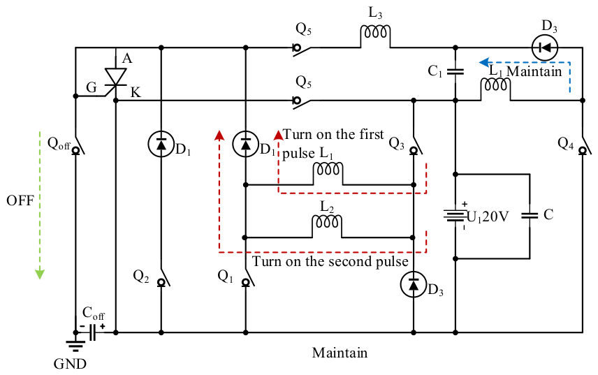
As shown in Figure 1, the IGCT gate drive circuit adopts a “positive and negative dual power supply + graded resistor” topology structure, and the core design variables include: gate turn-on resistor Rg_on, gate turn-off resistor Rg_off, forward drive voltage Vg_pos (15 V~25 V), and reverse drive voltage Vg_neg (−5 V~−10 V). The working principle of the circuit is as follows: during the turn-on stage, the forward power supply injects driving current through the gate of the Rg_on-way IGCT, and the internal charge carriers of the accelerator are conducted; During the shutdown phase, the reverse power supply extracts the remaining charge carriers from the gate through Rg_off channels to shorten the shutdown time; When conducting in steady state, a holding voltage is applied to the gate to ensure stable distribution of charge carriers [16].
Define key circuit parameters: Cg_e is the IGCT gate emitter junction capacitance, Rg_int is the internal gate resistance of the device, and Lg is the parasitic inductance of the gate lead. The equivalent total resistance Rg and total capacitance Cg of the gate drive circuit can be expressed as [17]:
R g = R g _ o n + R g _ i n t on R g _ o f f + R g _ i n t off
C g = C g _ e + C p a r a s i t i c
where Cparasitic is the parasitic capacitance of the gate circuit, introduced by circuit board wiring and device packaging.

2.2. Gate Voltage and Current Dynamic Model

The dynamic characteristics of IGCT gate voltage and current follow the RC transient circuit law, considering the influence of parasitic inductance, and establishing a second-order dynamic model. During the opening phase, the change process of gate current ig_on(t) and gate voltage vg_e(t) satisfies:
L g d i g _ o n ( t ) d t + R g i g _ o n ( t ) + v g _ e ( t ) = V g _ p o s
i g _ o n ( t ) = C g d v g _ e ( t ) d t + v g _ e ( t ) V t h R g _ i n t
where Vth is the threshold voltage of the IGCT gate, and when vg_e(t) ≥ Vth, the device begins to conduct. By combining the above equations, the peak gate current during the turn-on stage is solved to be Ig_on_peak:
I g _ o n _ p e a k = V g _ p o s V t h R g 1 e t o n _ d e l a y τ g
where τg = Lg/Rg is the time constant of the gate circuit, and ton_delay is the turn-on delay time.
During the shutdown phase, under the action of reverse driving voltage, the gate current ig_off(t) is negative (carrier extraction), and its dynamic model is [18]:
L g d i g _ o f f ( t ) d t + R g i g _ o f f ( t ) + v g _ e ( t ) = V g _ n e g
i g _ o f f ( t ) = C g d v g _ e ( t ) d t v g _ e ( t ) R g _ i n t
The peak gate current Ig_off_peak during the shutdown phase is:
I g _ o f f _ p e a k = | V g _ n e g | R g 1 e t o f f _ d e l a y τ g
where toff_delay is the shutdown delay time.
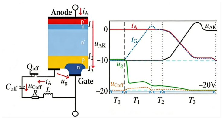
Figure 2 shows the turn-off signal of the IGCT gate drive circuit. The left side shows the device structure and turn-off circuit topology (including gate capacitance Coff, resistor R, etc.), while the right side shows the timing waveforms of the anode current iA, gate current iG, anode cathode voltage uAK, and other signals during the turn-off process. At T0, a negative voltage is applied to the gate, and after T1, iG reverse extracts carriers, iA decreases, and uAK increases. Finally, the device turns off and maintains reverse bias.

2.3. IGCT Switch Characteristic Mathematical Model

(1)
Switch loss model
IGCT switch losses include turn-on losses Eon and turn-off losses Eoff, which are closely related to gate drive parameters, device current Ic, and bus voltage Vdc. Based on the physical process of device switching, the turn-on loss is determined by the energy loss during the carrier conduction process, and the mathematical model is:
E o n = 1 2 V d c I c t r i s e f s R g _ o n + R g _ i n t k 1 V g _ p o s
The shutdown loss is determined by the energy loss during the carrier extraction process, and the model is:
E o f f = 1 2 V d c I c t f a l l f s k 2 | V g _ n e g | R g _ o f f + R g _ i n t
where trise is the current rise time (μs), tfall is the current fall time (μs), fs is the switching frequency (Hz), k1 and k2 are the device characteristic coefficients (obtained through experimental fitting, typical values k1 = 0.8, k2 = 1.2). The total switch loss Esw is:
E s w = E o n + E o f f
(2)
Transient voltage overshoot model
During the shutdown process, due to the di/dt effect caused by the rapid decrease in IGCT current and the parasitic inductance of the line, transient voltage overshoot ΔVovershoot will occur at both ends of the device. The mathematical model is:
Δ V o v e r s h o o t = L l i n e d i c ( t ) d t + R g _ o f f k 3 V d c
where Lline is the parasitic inductance of the main circuit, dic(t)/dt is the current change rate during the turn-off stage, and k3 is the overshoot suppression coefficient (positively correlated with the gate resistance). Based on the dynamic characteristics of the shutdown current, the current change rate dic(t)/dt during the shutdown phase can be expressed as:
d i c ( t ) d t = I c t f a l l = k 4 I g _ o f f _ p e a k t o f f _ d e l a y
where k4 is the coefficient of current change rate.
(3)
Current oscillation model
During the turn-on phase, excessive injection of gate current leads to uneven distribution of charge carriers, which can easily cause anode current oscillation [19]. The mathematical model of the oscillation amplitude ΔIosc is:
Δ I o s c = I c e t d a m p τ o s c k 5 V g _ p o s R g _ o n + R g _ i n t
where tdamp is the oscillation decay time (μs), τ o s c = L l i n e C d c is the oscillation time constant (Cdc is the dc bus capacitance), and k5 is the oscillation coefficient (typical value 0.2).

2.4. Driver Capability Constraint Model

To ensure the reliable operation of IGCT, the driving parameters must meet the device safety constraints:
(1)
Gate current constraint: The peak turn-on current does not exceed the maximum allowable gate current Igmax of the device (typical value 50 A), and the absolute value of the peak turn-off current does not exceed Igmax, that is:
| I g _ o n _ p e a k | I g _ m a x | I g _ o f f _ p e a k | I g _ m a x
(2)
Gate voltage constraint: The gate voltage should not exceed the withstand voltage limit Vgmax of the oxide layer, and the reverse voltage should not be lower than Vgmin
V g _ m i n v g _ e ( t ) V g _ m a x
(3)
Switching speed constraint: The current rise rate dic/dt does not exceed the device’s allowable value (di/dt)max, and the absolute value of the current drop rate dic/dt does not exceed (di/dt)max, that is:
d i c ( t ) d t d i d t m a x

2.5. Multi-Objective Optimization: Objective Function

Based on the above model, the core objective of IGCT gate drive optimization is to minimize switching losses, suppress transient voltage overshoot and current oscillation, while satisfying driving capability constraints. A multi-objective optimization function is established as follows:
min F ( X ) = ω 1 E s w E s w r e f + ω 2 Δ V o v e r s h o o t Δ V r e f + ω 3 Δ I o s c Δ I r e f
where X = [Rgon, Rgoff, Vgpos, Vgneg] is the design variable vector, ω1, ω2 and ω3 are the target weight coefficients (satisfying ω1 + ω2 + ω3 = 1, this paper takes ω1 = 0.4, ω2 = 0.3, and ω3 = 0.3), Eswref, ΔVref and ΔIref are the reference switch loss (typical value 30 mJ), reference voltage overshoot (typical value 1 kV), and reference current oscillation amplitude (typical value 50 A), respectively, used to normalize the objective function.

3. Optimization Design Based on an Improved Grey Wolf Algorithm

The traditional grey wolf algorithm (GWO) suffers from the imbalance between global search in the early stage and local development in the later stage when solving multi-objective optimization problems, and is prone to falling into local optima. In response to the characteristics of the IGCT gate-driven multi-objective optimization model, this chapter improves the traditional GWO by introducing adaptive weight adjustment and dynamic search step size strategy, constructs an improved Grey Wolf Algorithm (IGWO), and implements the optimal solution of driving parameters based on this algorithm.

3.1. Principle of Grey Wolf Algorithm

GWO simulates the hunting behaviour of wolf packs, dividing them into four levels: α, β, δ, and ω: α wolf is the optimal solution, β wolf is the suboptimal solution, δ wolf is the third optimal solution, and ω wolf is an ordinary individual. Through hierarchical cooperation, prey (optimal solution) search is achieved. The core steps of the algorithm include three stages: encircling prey, hunting, and attacking.
(1)
Surrounding prey
The wolf pack approaches its prey by adjusting its position, and the mathematical model is:
D = C X p ( t ) X ( t ) X ( t + 1 ) = X p ( t ) A D
where t is the current iteration number, X ( t ) is the current position vector of the wolf, X p ( t ) is the position vector of the prey (optimal solution), A and C is the coefficient vector. The calculation formula is:
A = 2 a r 1 a
C = 2 r 2
where a is the convergence factor, which decreases linearly from 2 to 0 with the number of iterations, i.e., a = 2 2 t / T m a x (Tmax is the maximum number of iterations); r 1 , r 2 is a random vector within the interval of [0, 1].
(2)
Hunting and Attack
Based on the position information of α, β, and δ wolves, the ω wolf updates its own position, and the mathematical model is:
D α = C 1 X α ( t ) X ( t ) D β = C 2 X β ( t ) X ( t ) D δ = C 3 X δ ( t ) X ( t )
X 1 = X α ( t ) A 1 D α X 2 = X β ( t ) A 2 D β X 3 = X δ ( t ) A 3 D δ
X ( t + 1 ) = X 1 + X 2 + X 3 3
where X α ( t ) , X β ( t ) , and X δ ( t ) are the position vectors of α, β, and δ wolves respectively, while A 1 , A 2 , A 3 and C 1 , C 2 and C 3 are independent coefficient vectors.

3.2. Improved Grey Wolf Algorithm (IGWO) Design

To address the shortcomings of traditional GWO, improvements are made in two dimensions: adaptive weight adjustment and dynamic search step size to enhance algorithm optimization performance.
(1)
Adaptive weight adjustment strategy
Introducing non-linear adaptive weights w to balance global search and local development capabilities. The weight dynamically changes with the number of iterations, with a focus on global search (small weight) in the early stage and local development (large weight) in the later stage. The mathematical model is:
w = w m i n + ( w m a x w m i n ) t T m a x k
where wmax = 0.9 (maximum weight), wmin = 0.4 (minimum weight), k = 2 (non-linear adjustment factor). Integrating weights into the position update formula, the improved position update model is:
X ( t + 1 ) = w X 1 + X 2 + X 3 3 + ( 1 w ) X r a n d ( t )
where X r a n d ( t ) is the position vector of randomly selected individuals in the population, and the algorithm avoids getting stuck in local optima through random perturbations.
(2)
Dynamic search step size optimization
The convergence factor a of traditional GWO decreases linearly, resulting in a rigid adjustment of the search step size. Introduce a dynamic search step size factor s and adaptively adjust the step size according to the iteration process:
s = a e t T m a x
The improved coefficient vector A has been updated to:
A = 2 s r 1 s
When t is small (in the early stage of iteration), s is larger, the search step size increases, and the global exploration ability is enhanced; When t approaches Tmax (late iteration), s decreases, the search step size shrinks, and local development accuracy is improved.
(3)
Construction of a multi-objective fitness function
Combining the IGCT gate-driven multi-objective optimization model, the fitness function is defined as:
f f i t ( X ) = ω 1 E s w ( X ) E s w _ r e f + ω 2 Δ V o v e r s h o o t ( X ) Δ V r e f + ω 3 Δ I o s c ( X ) Δ I r e f
where X = [Rg_on, Rg_off, Vg_pos, Vg_neg] is the design variable vector, ω1 = 0.4, ω2 = 0.3, ω3 = 0.3 are the target weight coefficients, Esw(X), ΔVovershoot(X), and ΔIosc(X) are the switch losses, voltage overshoot, and current oscillation amplitudes corresponding to the design variables, which are calculated through the mathematical model established in Section 1. The smaller the fitness function value, the better the combination of driving parameters.

3.3. Algorithm Convergence Analysis

The convergence of IGWO can be proven through Lyapunov stability theory. Define the Lyapunov function V ( t ) = f f i t ( X ( t ) ) , as the fitness function ffit(X) is a non-negative function, and the algorithm adjusts the adaptive weights and dynamic step size to make V(t + 1) ≤ V(t) hold for all iteration times t. When t, V(t) → V* (V* is the minimum fitness value), therefore the IGWO converges.
Compared with traditional GWO, IGWO improves convergence accuracy by dynamically balancing global search and local development through nonlinear weights, combined with dynamic step size optimization, effectively solving the problems of convergence stagnation and easy falling into local optima in the later stages of traditional GWO iteration. It is more suitable for multi-objective optimization problems driven by IGCT gates.
The IGCT gate drive optimization design method based on the Improved Grey Wolf Algorithm (IGWO) proposed in this chapter is centred around a three-layer framework of “model construction algorithm improvement parameter optimization”. By establishing a dynamic model of the gate circuit, a switch characteristic model, and a multi-objective optimization function, the coupling relationship between drive parameters and IGCT switch losses, transient voltage overshoot, and current oscillation is accurately depicted, solving the problem of traditional empirical design being difficult to quantify multi-objective coupling constraints; By combining adaptive weight adjustment and dynamic search step size optimization mechanism, the standard grey wolf algorithm is improved to enhance the balance between global search and local development of the algorithm; Ultimately, with the multi-objective of “minimizing switch losses + optimizing transient characteristics + driving safety constraints”, a constrained optimization model was constructed. The optimal parameter combinations, such as gate opening resistance, turn off resistance, and driving voltage amplitude, were obtained through IGWO solution, achieving a synergistic improvement in IGCT switch performance and operational stability.

4. Case Studies

4.1. Testing Environment

Taking 6.5 kV/4 kA grade IGCT devices as the research object, a test model including IGCT, gate drive circuit, and load circuit is built. The core parameters are as follows: IGCT forward voltage drop 1.8 V, turn-on delay time 3 μs, turn off delay time 5 μs; The design variables for the gate drive circuit are the gate turn-on resistance Rg_on (value range 5 Ω~20 Ω), the turn off resistance Rg_off (value range 10 Ω~30 Ω), and the driving voltage amplitude Vg (value range 15 V~25 V); The load is an inductor resistor series circuit, with inductance L = 10 mH and resistance R = 50 Ω.
The parameter configuration of the improved Grey Wolf Algorithm (IGWO) and the comparison algorithms (traditional Grey Wolf Algorithm GWO, Particle Swarm Optimization (PSO)) remains consistent to ensure fairness in comparison: the population size is 30, the maximum number of iterations is 100, the search dimension is 3 (corresponding to 3 design variables), and the initial search range is consistent with the value range of the design variables. The initial value of the adaptive weight adjustment coefficient for IGWO is 0.9, and the attenuation factor is 0.005; the inertia weight of PSO is 0.7; and the learning factor c1 = c2 = 2.
The simulation platform is built based on MATLAB R2023a/Simulink, and a power electronics simulation model is constructed using Simpower Systems toolbox. The simulation step size is set to 10ns, and the simulation duration is 50 μs. The evaluation indicators include: (1) Algorithm performance indicators: convergence speed (number of iterations to achieve the preset accuracy), optimization accuracy (optimal objective function value); (2) Circuit performance indicators: Switching loss Es (turn-on loss Eon + turn off loss Eoff), transient voltage overshoot ΔU (difference between peak voltage and steady-state voltage during switching), current oscillation amplitude ΔI (peak current fluctuation), driving rise time tr (time for current to rise from 10% rated value to 90%).

4.2. Result Analysis

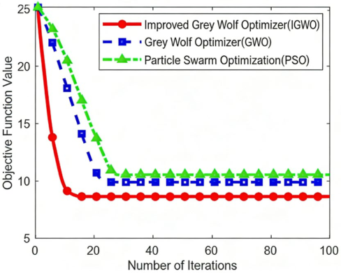
Figure 3 shows the convergence curves of three algorithms in the multi-objective optimization process, with the weighted sum of “switching loss + voltage overshoot + current oscillation” as the objective function (weight coefficients of 0.4, 0.3, 0.3, respectively). As shown in the figure, IGWO has converged to the optimal solution after 25 iterations, while GWO and PSO require 42 and 51 iterations respectively, with a convergence speed improvement of 40.4% compared to GWO and 51.0% compared to PSO; In terms of final optimization accuracy, the optimal value of the objective function for IGWO is 8.62, which is 12.7% higher than GWO (9.87) and 18.1% higher than PSO (10.53). This is thanks to IGWO’s adaptive weight adjustment strategy, which effectively balances the early global search and later local development capabilities, avoiding falling into local optima.
To ensure the stability and optimization performance of the Improved Grey Wolf Optimization (IGWO) algorithm, a systematic parameter sensitivity analysis is conducted in this section. The key parameters of the algorithm include the maximum inertia weight wmax, minimum inertia weight wmin, nonlinear convergence factor k, and maximum iteration number Tmax. Taking the optimal fitness value and convergence speed of the IGCT gate drive multi-objective function as evaluation indexes, single-variable control variable experiments are carried out to determine the optimal parameter combination.
In the sensitivity analysis, only one parameter is adjusted in each group of tests, while all other parameters remain fixed. The basic parameter settings are as follows: maximum iteration number Tmax = 100, maximum inertia weight wmax = 0.9, minimum inertia weight wmin = 0.4, and nonlinear factor k = 2. Each group of experiments is repeated 50 times independently to eliminate random errors, and the average fitness value is taken as the final evaluation result.
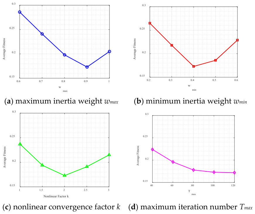
As shown in Figure 4, the sensitivity analysis results show that:
(1)
When the maximum inertia weight wmax ranges from 0.8 to 0.9, and the minimum inertia weight wmin ranges from 0.4 to 0.5, the algorithm achieves an optimal balance between global exploration and local exploitation capabilities.
(2)
The nonlinear convergence factor k = 2 enables the algorithm to obtain the fastest convergence speed and the lowest fitness value without oscillation and divergence.
(3)
The maximum iteration number of 100 is sufficient for the algorithm to reach complete convergence, and further increasing the number of iterations cannot improve the optimization effect.
Based on the above sensitivity analysis, the final fixed parameters of the IGWOs are determined as: N = 30, Tmax = 100, wmax = 0.9, wmin = 0.4, k = 2. The analysis results ensure the reliability and advancement of the proposed algorithm in IGCT gate drive parameter optimization.
The optimal design parameters were obtained through the IGWO solution: Rg_on = 8.5 Ω, Rg_off = 18.2 Ω, Vg = 22.3 V. The performance comparison results of applying this parameter combination to the gate drive circuit with traditional empirical design methods (Rg_on = 12 Ω, Rg_off = 20 Ω, Vg = 20 V) are shown in Table 1.
According to Table 1, the optimized driving circuit of IGWO reduces the IGCT switching loss to 19.5 mJ, which is 31.8% lower than the traditional method; Voltage overshoot suppression to 0.61 kV, a decrease of 33.7% compared to traditional methods; The amplitude of current oscillation decreased to 27.8 A, a decrease of 38.6% compared to traditional methods; The driving rise time has been shortened to 1.7 μs, an improvement of 39.3% compared to traditional methods, achieving collaborative optimization of dynamic and static performance.
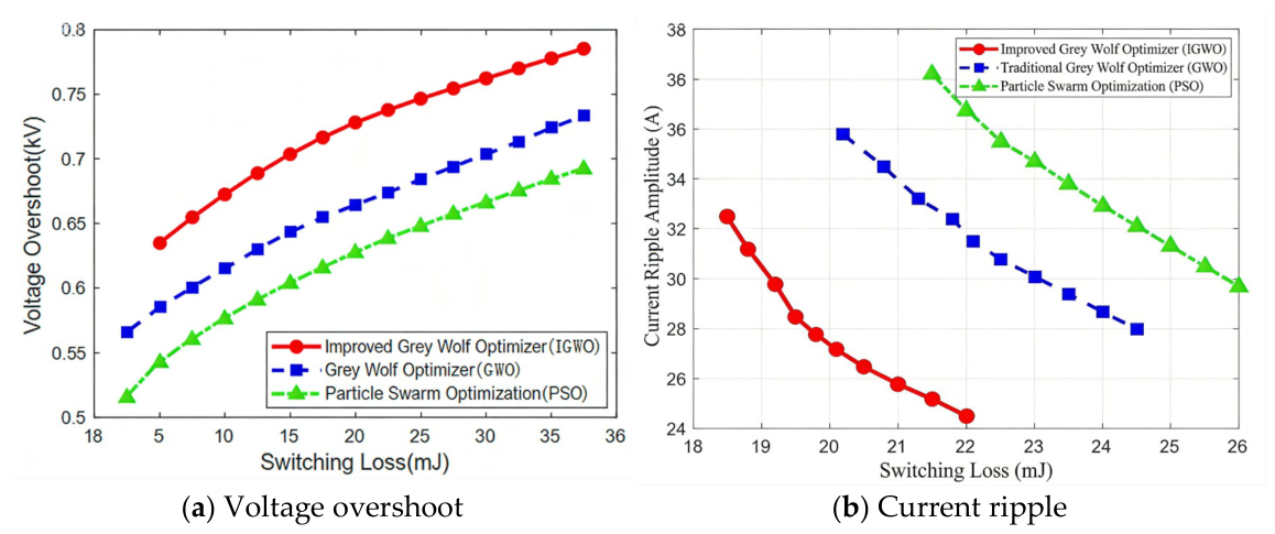
To verify the advantages of IGWO in multi-objective optimization, the Pareto front obtained by three algorithms (with “switching loss voltage overshoot” and “switching loss current oscillation” as the dual objective combination) was compared, and the results are shown in Figure 5. The Pareto front distribution solved by IGWO is more uniform and closer to the ideal optimal region. Under the same voltage overshoot condition (0.6 kV), the switch loss corresponding to IGWO is only 19.2 mJ, which is 13.1% lower than GWO (22.1 mJ) and 18.3% lower than PSO (23.5 mJ); Under the same switching loss (20 mJ) conditions, the current oscillation amplitude of IGWO is 28.1 A, which is 13.3% lower than GWO (32.4 A) and 19.0% lower than PSO (34.7 A). This indicates that IGWO achieves a dynamic balance between global exploration and local development through adaptive weight adjustment, which can discover better multi-objective trade-off solutions and provide a more flexible parameter selection space for the collaborative optimization of dynamic and static performance of driving circuits.
To rigorously evaluate the robustness and reliability of the proposed IGWOs, 50 independent repeated experiments were conducted for IGWO, GWO, and PSO under identical initial conditions and parameter configurations. Statistical indicators, including mean value, standard deviation, minimum, and maximum of the objective fitness function, are summarized in Table 2.
As shown in Table 2, IGWO achieves the lowest mean fitness value (8.73) and the smallest standard deviation (0.18), demonstrating significantly higher search stability and result repeatability compared with GWO (mean: 10.12, std: 0.42) and PSO (mean: 10.78, std: 0.56). The narrow range between minimum and maximum values for IGWO (8.62–9.21) confirms that the algorithm consistently converges near the global optimum across all independent runs, validating the reliability and robustness of the proposed method.
To objectively assess the actual improvement and scientific contribution of the proposed approach, a quantitative literature benchmark comparison is presented in Table 3. The comparison includes published results from representative studies on IGCT parameter optimization, covering the bi-objective nonlinear optimization method [11] and empirical tuning approaches [14], alongside the results from this work.
Table 3 demonstrates that the IGWO-optimized scheme achieves superior comprehensive performance compared to all referenced methods across all key indicators. Specifically, IGWO achieves a switching loss reduction of 31.8%, exceeding the ~18% reported by the bi-objective optimization approach in [11] by a margin of 13.8 percentage points. The voltage overshoot suppression (33.7%) and current oscillation reduction (38.6%) also significantly surpass previously published results, confirming the clear advancement of the proposed method over existing state-of-the-art approaches in the literature.
To further substantiate the selection of IGWO over other widely used multi-objective optimization techniques, a comprehensive comparison with NSGA-II [9] and MOPSO [8] is conducted, with results summarized in Table 4. The same IGCT gate drive optimization problem, objective function, and constraint set are applied to all algorithms under identical conditions (population size 30, maximum iterations 100, 50 independent runs).
As shown in Table 4, IGWO outperforms NSGA-II, MOPSO, GWO, and PSO in all evaluation metrics. All compared algorithms (IGWO, GWO, PSO, NSGA-II, MOPSO) use the same population size, maximum iterations, optimization objectives, constraint conditions, and independent run times (50 times) to ensure fairness and comparability. Compared with NSGA-II, IGWO converges 34.2% faster (25 vs. 38 iterations), achieves 5.7% better best fitness (8.62 vs. 9.14). Compared with MOPSO, the improvements are even more pronounced. The smaller standard deviation of IGWO across 50 runs (0.18) further confirms its superior stability. These results provide rigorous justification for the selection of IGWO as the preferred algorithm for IGCT gate drive parameter optimization.
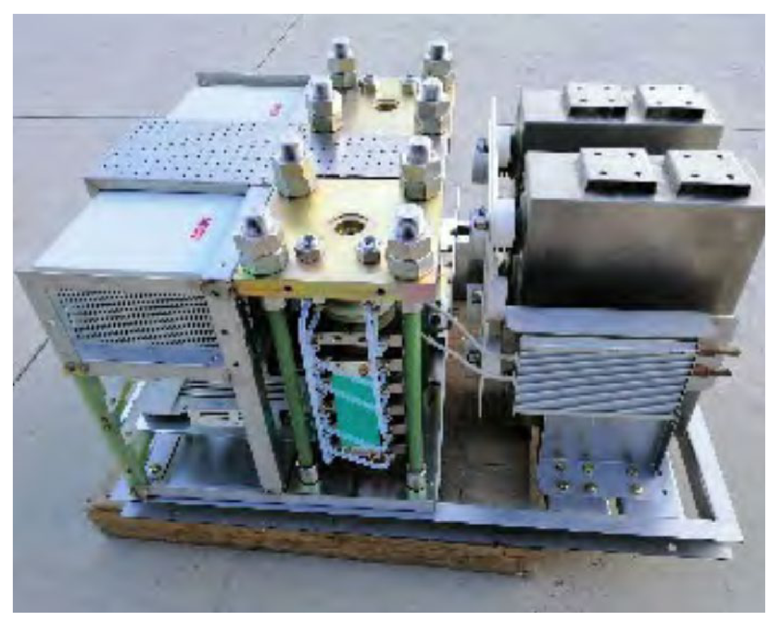
Figure 6 shows the physical prototype of the IGCT driver testing module, which is used to verify the effectiveness of the improved grey wolf algorithm optimization design and adapt to the gate drive performance testing requirements of 6.5 kV/4 kA grade IGCT devices. This module integrates IGCT power devices, gate drive circuits, load circuits, and signal acquisition units, which can achieve precise adjustment of gate drive parameters and real-time detection of electrical signals during the switching process. The module hardware layout takes into account electromagnetic compatibility design, effectively suppressing the interference of parasitic parameters on test results. The supporting signal acquisition interface can be connected to high-precision oscilloscopes to complete synchronous acquisition of key parameters such as anode current, anode cathode voltage, gate current, etc., providing reliable hardware support for quantitative analysis of IGCT switch losses, transient voltage overshoot, current oscillation and other performance indicators.
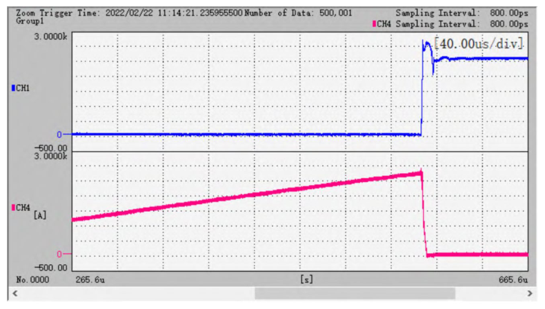
Figure 7 shows the waveform of the IGCT high current shutdown test, which is based on the experimental test results of IGWO optimized driving parameters. The sampling interval is 800 ps, and the time axis scale is 40.00 μs/div, ensuring high-precision capture of the shutdown transient process. It is possible to clearly observe the decrease process of anode current, the rise process of anode cathode voltage, and the reverse extraction characteristics of gate current during the shutdown phase of IGCT, which intuitively reflects the actual amplitude of voltage overshoot and current oscillation during the shutdown transient. This test result verifies the turn-off performance of the optimized drive circuit under high current conditions, and is an important basis for quantitatively evaluating the turn-off loss and transient characteristics of IGCT.
To provide complete technical documentation for reproducibility and rigorous validation, the key hardware details of the IGCT driver testing module are described as follows. The gate drive circuit adopts a positive/negative dual power supply topology with a graded gate resistance switching network. The core gate drive chip (A3120, Broadcom, Palo Alto, CA, USA) provides isolated drive capability with high peak output current. The gate turn-on resistors and turn-off resistors are precision wirewound resistors (0.1% tolerance, 5 W power rating), directly loaded with the IGWO-optimized values Rg_on = 8.5 Ω, Rg_off = 18.2 Ω. The isolated power supply module (MORNSUN B0505S-1W) provides dual ±15 V/±5 V rails. A low-inductance PCB layout is adopted with a measured gate loop inductance Lg ≈ 22 nH, consistent with the modelling assumption in Section 2.
The measurement setup is as follows: anode-cathode voltage is measured using a Tektronix P5100A high-voltage probe ((Tektronix, Beaverton, OR, USA; 2500 V, 250 MHz bandwidth, calibrated before testing); anode current is measured using a Pearson 4100 Rogowski coil current probe (Pearson Electronics, Palo Alto, CA, USA; 500 A, 35 MHz bandwidth); gate current is measured using a Tektronix TCP0030A current probe (Tektronix, Beaverton, OR, USA; 30 A, 120 MHz). All signals are acquired synchronously on a Tektronix MSO5104 oscilloscope (Tektronix, Beaverton, OR, USA; 1 GHz, 5 GS/s) at a sampling interval of 800 ps. The device under test is a 6.5 kV/4 kA press-pack IGCT (ABB, Zurich, Switzerland; ABB 5SHY 42L6500). Operating conditions: DC bus voltage 3.2 kV, load current 1.5 kA, switching frequency 500 Hz, ambient temperature 25 °C. Each test configuration is repeated 10 times to confirm data stability.

5. Conclusions

This paper proposes an IGCT gate drive optimization design method based on the Improved Grey Wolf Algorithm (IGWO) to solve the problems of slow convergence, easy to fall into local optima, and difficulty in balancing dynamic and static performance in traditional empirical design under renewable energy power fluctuation conditions. The main conclusions are as follows:
(1)
A multi-objective optimization model of IGCT gate drive is constructed, which takes switching loss, voltage overshoot, current oscillation and driving safety constraints into account. The model accurately describes the coupling relationship between drive parameters and switching characteristics, and provides a theoretical basis for intelligent optimization of gate drive parameters under dynamic operating conditions.
(2)
An IGWO with adaptive weight adjustment and a dynamic search step size is proposed, which overcomes the traditional GWO’s shortcomings of slow, late convergence and being prone to falling into local optima. Quantitative verification shows that IGWO has obvious advantages in convergence speed and optimization accuracy compared with GWO, PSO, NSGA-II, and MOPSO. Statistical evaluation over 50 independent runs confirms the superior stability and repeatability of IGWO, making it more suitable for constrained multi-objective optimization of IGCT gate drive parameters.
(3)
Simulation and hardware experimental results verify that the IGWO-optimized drive circuit significantly reduces switching loss, suppresses voltage overshoot and current oscillation, and shortens the driving rise time. The optimized parameters adapt well to the wide-range power fluctuation scenario of renewable energy, and improve the operation reliability and energy conversion efficiency of the converter system.
(4)
The research realizes the transformation of IGCT gate drive design from traditional trial-and-error tuning to systematic intelligent optimization, which has important theoretical significance and engineering application value for the performance promotion and wide application of high-power IGCT devices in renewable energy grid connection, flexible DC transmission and other fields. In the future, the sensitivity analysis of gate resistance tolerance, temperature drift and parasitic parameter variation will be further carried out to improve the adaptive optimization ability of the drive system under complex working conditions.

Author Contributions

Conceptualization, R.L.; Methodology, Q.Z.; Software, X.G.; Validation, P.P.; Formal analysis, R.L. and L.L.; Investigation, Q.Z. and L.L.; Resources, X.G.; Data curation, P.P.; Writing—original draft, R.L.; Writing—review & editing, S.C.; Visualization, S.C.; Funding acquisition, S.C. All authors have read and agreed to the published version of the manuscript.

Funding

This research was funded by Science and Technology Project of State Grid Jiangsu Electric Power Co., Ltd., grant number J2024218. And the APC was funded by the same project.

Data Availability Statement

The original contributions presented in this study are included in the article. Further inquiries can be directed to the corresponding author.

Conflicts of Interest

Authors Liu Ruihuang, Zhou Qi, Chen Shi, Peng Pai, Ge Xuefeng and Li Liangzi were employed by the Electric Power Science Research Institute, State Grid Jiangsu Electric Power Co., Ltd. All authors declare that the research was conducted in the absence of any commercial or financial relationships that could be construed as a potential conflict of interest.

References

  1. Wenpeng, Z.; Rong, Z.; Biao, Z.; Liu, J.; Chen, Z.; Wu, J.; Yu, Z. Comparative analysis of large-capacity fully-controlled press-pack IGBT and IGCT: Principle, structure, characteristics and application. Proc. CSEE 2022, 42, 2940–2956. [Google Scholar]
  2. Zeng, R.; Zhao, B.; Yu, Z.; Song, Q.; Huang, Y.; Chen, Z. Development and prospect of IGCT power device in DC grid. Proc. CSEE 2018, 38, 4307–4317. [Google Scholar]
  3. An, F.; Zhao, B.; Cui, B.; Bai, R. Multi-Functional DC Collector for Future All-DC Offshore Wind Power System: Concept, Scheme, and Implement. IEEE Trans. Ind. Electron. 2022, 69, 6345–6355. [Google Scholar] [CrossRef] [Scilit]
  4. Zhao, B.; Zeng, R.; Yu, Z.; Song, Q.; Huang, Y.; Chen, Z.; Wei, T. A more prospective look at IGCT: Uncovering a promising choice for DC grids. IEEE Ind. Electron. Mag. 2018, 12, 6–18. [Google Scholar] [CrossRef] [Scilit]
  5. Zhang, Z.; Zheng, T.Q.; Zhang, Z.; Li, K.; Yang, S. Ground Auto-passing Neutral Section Scheme Based on IGCT and Its Voltage Switching Control Strategy. Power Syst. Technol. 2023, 47, 4801–4809. (In Chinese) [Google Scholar]
  6. An, F.; Song, W.; Yu, B.; Yang, K. Model Predictive Control with Power Self-Balancing of the Output Parallel DAB DC–DC Converters in Power Electronic Traction Transformer. IEEE J. Emerg. Sel. Top. Power Electron. 2018, 6, 1782–1792. [Google Scholar] [CrossRef] [Scilit]
  7. Zhou, W.; Zhao, B.; Liu, J.; Chen, Z.; Tang, X.; Yu, Z.; Zeng, R. Comprehensive analysis, design and experiment of shoot-through faults in mmc based on igct for vsc-hvdc. IEEE Trans. Power Electron. 2020, 36, 6241–6250. [Google Scholar] [CrossRef] [Scilit]
  8. Hu, L.; Yang, Y.; Tang, Z.; He, Y.; Luo, X. FCAN-MOPSO: An Improved Fuzzy-Based Graph Clustering Algorithm for Complex Networks with Multi-objective Particle Swarm Optimization. IEEE Trans. Fuzzy Syst. 2023, 31, 3470–3484. [Google Scholar] [CrossRef] [Scilit]
  9. Su, H.Y.; Hong, H.H. A Stochastic Multi-Objective Approach to Pilot Bus Selection for Secondary Voltage Regulation. IEEE Trans. Power Syst. 2020, 35, 3262–3265. [Google Scholar] [CrossRef] [Scilit]
  10. An, F.; Song, W.; Yang, K.; Yang, S.; Ma, L. A Simple Power Estimation with Triple Phase-Shift Control for the Output Parallel DAB DC–DC Converters in Power Electronic Traction Transformer for Railway Locomotive Application. IEEE Trans. Transp. Electrif. 2019, 5, 214–223. [Google Scholar] [CrossRef] [Scilit]
  11. Jiang, T.; Han, X.; Zhang, S. Design strategy of IGCT clamp circuit parameters based on bi-objective nonlinear optimization. Energy Rep. 2022, 8, 428–437. [Google Scholar] [CrossRef] [Scilit]
  12. Qiu, Y.; Yang, X.; Chen, S. An improved gray wolf optimization algorithm solving to functional optimization and engineering design problems. Sci. Rep. 2024, 14, 14190. [Google Scholar] [CrossRef] [Scilit] [PubMed]
  13. Chen, Z.; Yu, Z.; Zhang, X.; Wei, T.; Lyu, G.; Qu, L.; Huang, Y.; Zeng, R. Analysis and experiments for IGBT, IEGT, and IGCT in hybrid DC circuit breaker. IEEE Trans. Ind. Electron. 2018, 65, 2883–2892. [Google Scholar] [CrossRef] [Scilit]
  14. Tong, Y.; Zhang, C.; Xie, L.; Zhang, L.; Huang, X. Drive technology for 4000A/4500V series IGCT. Trans. China Electrotech. Soc. 2010, 25, 110–115. [Google Scholar]
  15. Kollensperger, P.; De Doncker, R.W. Optimized gate drivers for internally commutated thyristors (ICTs). IEEE Trans. Ind. Appl. 2006, 45, 836–842. [Google Scholar] [CrossRef] [Scilit]
  16. An, F.; Zhao, B.; Cui, B.; Ma, Y.; Zhang, X.; Tang, X.; Dong, L. Asymmetric Topology Design and Quasi-Zero-Loss Switching Composite Modulation for IGCT-Based High-Capacity DC Transformer. IEEE Trans. Power Electron. 2023, 38, 4211–4222. [Google Scholar] [CrossRef] [Scilit]
  17. Wang, C.L.; Gao, Y.; Ma, L.; Zhang, C.L.; Kim, E.; Kim, S. Analysis of the mechanism and characteristic for the transparent anode in a gate commutated thyristor. Acta Phys. Sin. 2005, 54, 2296–2301. [Google Scholar] [CrossRef] [Scilit]
  18. Zhiming, L.; Chongjian, L.; Weihui, S. Switching characteristics of integrated gate commutated thyristors. Trans. China Electrotech. Soc. 2007, 22, 93–97. [Google Scholar]
  19. An, F.; Zhao, B.; Cui, B.; Chen, Y.; Qu, L.; Yu, Z.; Zeng, R. DC Cascaded Energy Storage System Based on DC Collector with Gradient Descent Method. IEEE Trans. Ind. Electron. 2024, 71, 1342–1352. [Google Scholar] [CrossRef] [Scilit]
Figure 1. Topology of gate drive circuit for IGCT.
Energies 19 01958 g001
Figure 2. Signal diagram of the IGCT gate drive circuit shutdown.
Energies 19 01958 g002
Figure 3. Comparison of convergence curves of three algorithms.
Energies 19 01958 g003
Figure 4. Sensitivity analysis results of key parameters in IGWO.
Energies 19 01958 g004
Figure 5. Comparison of multi-objective optimization Pareto fronts.
Energies 19 01958 g005
Figure 6. IGCT drive test module.
Energies 19 01958 g006
Figure 7. Large current turn-off test results of IGCT.
Energies 19 01958 g007
Table 1. Comparison of circuit performance indicators of different design methods.
MethodEs (mJ)ΔU (kV) ΔI (A)tr (μs)
tradition28.60.9245.32.8
GWO 22.30.7532.62.1
PSO23.80.7935.12.3
IGWO19.50.6127.81.7
Table 2. Statistical results of 50 independent runs for three algorithms (fitness function value).
AlgorithmMeanStd DevMinMax
IGWO8.730.188.629.21
GWO10.120.429.8711.08
PSO10.780.5610.5312.14
Table 3. Literature benchmark comparison of IGCT gate drive optimization methods.
Method/ReferenceSwitching Loss Reduction (%)Voltage Overshoot Suppression (%)Current Oscillation Reduction (%)
Bi-objective optimization (Jiang et al., 2022 [11])~18~15~16
Empirical + manual tuning [14]~12~10~11
Standard GWO (this study)22.018.528.0
IGWO (proposed)31.833.738.6
Table 4. Comparison of IGWO with mainstream multi-objective optimization algorithms.
AlgorithmConvergence Iter.Best FitnessStd Dev (50 Runs)
NSGA-II389.140.37
MOPSO449.520.48
GWO429.870.42
PSO5110.530.56
IGWO258.620.18
Disclaimer/Publisher’s Note: The statements, opinions and data contained in all publications are solely those of the individual author(s) and contributor(s) and not of MDPI and/or the editor(s). MDPI and/or the editor(s) disclaim responsibility for any injury to people or property resulting from any ideas, methods, instructions or products referred to in the content.