


Abstract
In large-scale offshore wind power transmission systems, the offshore converter valves are typically based on the half-bridge Modular Multilevel Converter (MMC) topology. This design leads to considerable weight and high costs, presenting a critical bottleneck for the development of offshore wind power transmission. This paper proposes a hybrid topology consisting of paralleled MMCs connected in series with a Diode Rectifier Unit (DRU) to achieve lightweight offshore converter valves. The parallel configuration enhances the steady-state current-carrying capacity of the valve group to match the DRU valve group, and power balance among the paralleled MMCs is realized through an additional DC current-sharing control loop. A calculation method for the main circuit parameters of this lightweight topology is presented, along with a complete parameter calculation process. A design example based on actual engineering capacity is provided. PSCAD simulation results verify that the electrical quantities during steady-state operation of the hybrid topology are consistent with the designed parameters, confirming the correctness of the proposed parameter calculation method.
1. Introduction
In recent years, offshore wind power has seen large-scale development. Nearshore wind farms are typically connected directly to the onshore AC power grid via step-up transformers. However, for deep-sea wind farms, Voltage source converter-based high voltage direct current (VSC-HVDC) transmission systems are generally used to connect to the onshore AC system. A typical offshore wind farm operates with an AC bus voltage of 66 kV, which is stepped up by an offshore substation transformer before being connected to the offshore converter station. At the station, the power is converted to DC and transmitted via long-distance submarine cables to an onshore converter station, where it is inverted back to AC and integrated into the grid. A typical offshore wind power grid integration system using VSC HVDC has a DC voltage of ±500 kV and a capacity of 2000 MW, such as the completed Rudong offshore wind farm integration project and the Yangjiang project. The offshore converter stations employ a half-bridge MMC topology. The offshore station is typically designed to be lightweight, optimizing the valve tower structure and taking measures such as removing valve tower frames to reduce the weight of the offshore platform. However, the MMC topology includes numerous DC-side capacitors, whose total weight is relatively large, leading to increased construction costs for the offshore platform. Furthermore, the MMC itself requires a large number of power devices, resulting in high construction and maintenance costs for the converter valves. This is one of the key factors limiting the construction of grid integration projects for deep-sea wind farms.
In the research on lightweight topologies for offshore converter valves, the main technological routes include hybrid topologies, low-frequency transmission, and medium-frequency transmission. Ref. [1] proposes a topology where the DRU and the full-bridge MMC are connected in series on the DC side and in parallel on the AC side to serve as the offshore converter valve. In this configuration, the MMC transmits only a portion of the power and facilitates the black start of the wind farm, while the DRU valve group bears the majority of the DC voltage and power. This design can significantly reduce the volume and weight of the offshore converter valve. The paper specifies the proportion of the MMC’s DC voltage relative to the total voltage, calculates the active and reactive power capacities of the MMC, designs the basic parameters of the converter valves, and establishes the grid-forming control strategy for the MMC. In [2], it focuses on the hybrid topology and proposes the addition of a DC voltage outer loop based on the traditional wind turbine grid-forming control strategy employing AC voltage-current double closed loops. By regulating the DC voltage, this approach can reduce the capacity proportion of the series-connected MMC within the stable operating range of the system. In [3,4] a method based on repetitive control is proposed for the hybrid topology with parallel-connected DRU and MMC, where the parallel MMC is utilized to suppress the AC-side harmonics of the DRU. This eliminates the need for AC filters in the DRU, thereby reducing system costs. In [5], the commutation process and harmonic characteristics of the diode valves are further analyzed, and a design scheme is proposed in which a parallel VSC is used to achieve black start of the wind farm and compensate for the AC-side voltage harmonics of the diode valves. In [6], a topology comprising an MMC and a double 12-pulse DRU is proposed, and the steady-state commutation process of the DRU valves in this topology is analyzed. In [7], an impedance model of the hybrid topology was established, proposing that the control parameters have different effects on the system stability boundary at different power operating points. In [8], a method is proposed to connect an energy dissipation resistor, controlled by thyristor valves, in parallel with the DC side of the series-connected full-bridge MMC, in order to achieve active power balance during the black start of the wind farm. In [9], the fault ride-through method for converter valves in a parallel DRU and MMC configuration is analyzed, and it is proposed that during an AC bus fault at the wind farm, the wind turbines reduce their output current to coordinate with the offshore converter station in achieving fault ride-through.
If a separate diode valve is adopted for the offshore station, equipment costs and volume can be further reduced, but the black start of the wind farm and the design of grid-forming control strategies for wind turbines need to be considered. In [10], a full-bridge MMC is connected in series with a diode rectifier, with the MMC operating in grid-forming mode to provide AC voltage support. The focus is on control strategies for black start and grid-forming operation. In [11], the MMC also operates as a grid-forming converter to support the offshore AC grid, while the DRU handles the majority of power transmission. It also focuses on the operational principle and basic control strategy. In [12,13,14], for wind farms connected via diode valves, it is necessary to configure an additional auxiliary converter as a black start power source for the wind farm, or to set up an independent MMC valve and transmission channel as an additional sending end. The MMC transmission channel is configured according to a certain capacity proportion, with the AC sides of the two connected in parallel, while the DC sides adopt independent DC lines [15]. This approach reduces the DC voltage of the MMC, decreases the number of submodules, and achieves the black start function for the wind farm. In [16], with the DRU valve serving as the offshore converter station, a diesel generator is configured to start a portion of the wind turbines. A start-up scheme and a detailed start-up process for the grid-forming wind turbine transmission system via the DRU are proposed. It is also pointed out that when starting the first wind turbine, the reactive power load demand of the offshore station must be satisfied. In [17], considering limiting factors such as rated capacity and reactive power demand, the power operating range of the MMC in the hybrid topology is calculated. It is proposed that the reactive power of the DRU be shared among the wind farm, passive compensation devices, and the offshore MMC to reduce the rated capacity of the MMC. In [18], focusing on the configuration where diode valves are used independently as the offshore station, the system stability is analyzed for scenarios involving grid-forming and grid-following wind turbines. A mathematical model of the system is established, and by considering constraints such as reactive power consumption, the Stability regions for the capacity allocation ratios of grid-following wind turbines, grid-forming wind turbines, and reactive power compensation devices are derived. In [19], a grid-forming control strategy for wind turbines in an offshore wind farm directly connected to a diode valve converter system is proposed, and the stability of the control structure of the equivalent unit is analyzed. In [20,21], based on the conventional P-V and Q-f control strategies, an improved distributed control method for wind turbines is proposed to address the issue of large fluctuations in AC voltage and frequency during transient processes. In [22], the relationship between the AC bus voltage and frequency of grid-forming wind turbines and their output active power is analyzed. It is proposed to use the AC frequency of the grid-forming wind farm as a feedforward control quantity to regulate the power of the onshore station MMC, thereby avoiding oscillations in offshore wind turbines. In [23], focusing on the stability issues of grid-forming control strategies for wind turbine grid-side converters, the influence of wind turbine grid-forming control parameters on system stability is analyzed. Principles for selecting the values of the reactive power droop control coefficient and the control coefficients of the reactive power-frequency outer loop of the wind turbine converter are proposed. It is pointed out that different values of control parameters have a significant impact on system stability. In [24,25], a fault ride-through strategy for the grid-side of the onshore station is proposed. By comprehensively utilizing the energy stored in the MMC capacitors and the inertial energy of the wind turbines to buffer the surplus power from the wind farm, the strategy achieves fault ride-through on the grid side of the onshore station.
As discussed in the aforementioned literature, the adoption of hybrid topology converter valves can significantly reduce the cost and weight of converter stations, making it one of the main technical routes for the lightweight design of offshore converter stations [26]. Hybrid topologies are typically composed of DRUs and MMCs connected in series or in parallel. For the topology where wind turbines are directly connected to the DRU, a small-capacity MMC is usually required as a black start power source for the wind farm [27], and grid-forming control strategies for the wind turbines need to be designed. This has a considerable impact on the control strategies of existing wind turbine converters in practice. For the series topology of DRU and MMC, the series-connected MMC can enable the black start of the wind farm and operate in grid-forming mode to provide AC voltage support for the wind farm [28]. In this case, the converters of the wind turbines maintain conventional grid-following control, resulting in relatively mature control strategies.
However, the capacity and voltage level of the series-connected MMC must meet the start-up and operational requirements of the wind farm. Numerous factors influence the MMC design, yet detailed parameter design schemes are scarcely discussed in existing literature. This paper focuses on the series topology of the DRU and MMC. It analyzes the relationships among the electrical quantities of the converter valves, designs the hybrid topology parameters for the DRU and MMC, provides a parameter design example based on the capacity of a typical offshore wind farm, and verifies the correctness of the system parameters through simulation. The main contributions include: (1) a complete parameter design procedure for the DRU-MMC series valve group, deriving key equations for voltage ratio, reactive power consumption, and component selection; (2) a parallel MMC configuration to enhance current-carrying capacity and match the high current rating of the DRU; and (3) a dedicated current-sharing control strategy to ensure balanced power distribution between the parallel MMCs. These contributions provide a practical foundation for lightweight converter valve design in large-scale offshore wind farms.
2. Hybrid Converter Topology (Methods & Materials)
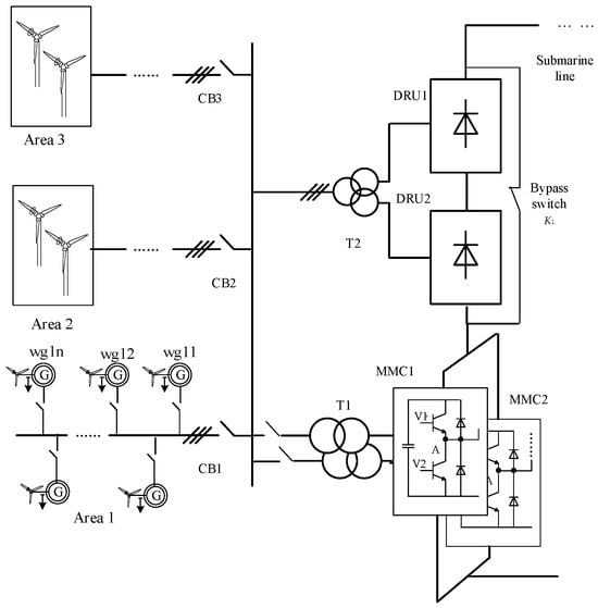
Considering that the current-carrying capacity of the DRU is significantly higher than that of the MMC, this paper proposes connecting the MMCs in parallel on the DC side and then in series with the DRU, thereby fully utilizing the current-carrying capability of the DRU valve group. The proposed hybrid topology is shown in Figure 1. In the figure, the wind farm is divided into 3 groups, which are connected in parallel to the common AC bus via circuit breakers CB1~CB3, respectively, and the DRU is a 12-pulse rectifier bridge connected in series with the half-bridge MMC. The DC side of the DRU is connected in parallel with a bypass switch K1. During the start-up phase of the wind farm, K1 is closed, and the DC sides of the parallel-connected MMC1 and MMC2 are directly connected to the onshore station. The onshore converter station typically adopts a hybrid full-bridge and half-bridge topology, operating at reduced voltage during the start-up phase. Through the bypass switch K1 and the offshore station MMCs, an AC voltage is established for the wind farm, completing the black start of the wind farm.
Figure 1.
DRU and MMC series hybrid topology converter.
3. Parameter Design of Converter Valves (Methods & Materials)
3.1. Parameter Design of DRU Valves
In the hybrid topology, the MMC and the DRU are connected in series. Therefore, the DC current flowing through the DRU and the MMC is equal. Under steady-state conditions, the DC voltage ratio between the DRU and the MMC is equal to the ratio of their output active power. That is,
where Udru is the DC-side voltage of the DRU, and Ummc_dc is the DC-side voltage of the MMC. The AC sides of the DRU and the MMC are connected in parallel, and the AC bus voltage is established by the MMC. Typically, the DRU is a 12-pulse rectifier bridge; therefore, the relationship between the AC voltage and the DC voltage of the DRU is given by Equation (2).
where UL is the RMS line-to-line AC voltage of the DRU. In the hybrid topology, UL is established by the MMC. For a 12-pulse DRU, KD = 2. Under steady-state conditions, the equivalent reactance of the DRU’s AC transformer causes a voltage drop [29], as shown in Equation (3).
where m is the number of commutations of the DRU within one power frequency cycle. For a three-phase bridge circuit, m = 6. Therefore, the DC voltage of the 12-pulse DRU is given by Equation (4).
During steady-state operation, the wind turbine converter typically operates at a unity power factor. The MMC is required to provide the reactive power consumed by the DRU valves, the AC transformer, and the AC submarine cables. Based on preliminary selection from Equations (1) and (4), the DC voltage ratio of the MMC to the DRU is set at 1:10 for a typical ±500 kV DC 2000 MW offshore wind farm. The DRU has a rated active power of 1800 MW. Under full-power operation, the reactive power consumed by the DRU is given by Equation (5).
where μ is the commutation overlap angle, and its relationship with the DC current is given by Equation (6), where XB is the leakage reactance of the transformer. Furthermore, based on the DC current Idc and Equations (5) and (6), the commutation overlap angle of the diode valves and the reactive power can be estimated.
Based on the above equations, the parameters of the converter valves in a typical 2000 MW wind power transmission system can be calculated. The DRU has a rated capacity of 1800 MW, and its main circuit parameters are shown in Table 1.
Table 1.
DRU parameters.
3.2. Parameter Design of MMC Valves
For the typical offshore wind power transmission topology shown in Figure 1, the reactive power consumed by the DRU valves, offshore station transformers, and submarine cables during startup and steady-state operation is all provided by the MMC. As mentioned earlier, during steady-state operation, the MMC needs to output approximately 326 Mvar of inductive reactive power. During the wind farm startup, the MMC is required to provide capacitive reactive power for the wind farm submarine cables and wind turbines. To reduce the reactive power demand on the MMC, only one of the wind farm collector buses (e.g., L1 in Area 1 of Figure 1) is first connected to the AC bus of the offshore converter station, CB1 is closed, and 1–2 wind turbines (e.g., wg11 and wg12) are started. Therefore, during the wind farm startup process, the MMC only needs to provide the reactive power for charging the AC collector submarine cable L1. It can be estimated that the reactive power Qstart required from the MMC during the black start includes: the reactive power of the AC submarine cable QL1, the pre-charging reactive power of the wind turbine converters Qcw11 and Qcw12, and the reactive power of the converter station transformer QT1. Taking a typical 2000 MW wind farm as an example, the wind turbines are connected to the offshore converter station via 35 kV submarine cables. The typical capacitance-to-ground of AC submarine cables at this voltage level is approximately 0.3 μF/km. Assuming the average distance between the wind turbines connected to each AC collector cable and the offshore converter station is 50 km, the reactive power consumed by a single group of AC submarine cables is approximately 6 Mvar. The reactive power of the wind turbine converter capacitors is estimated at 3% of their own capacity. During the startup charging, the wind turbines do not output power, and the current is relatively small, so the reactive power loss caused by transformer leakage reactance is neglected. During the startup, the MMC primarily provides capacitive reactive power, as shown in Equation (7). For the system in Figure 1, the typical reactive power demand is approximately 6.15 Mvar.
Qstart = Qcw11 + Qcw12 + QL1
In the aforementioned design, the peak AC-side voltage of the MMC can be calculated based on the DC voltage ratio between the DRU and the MMC. Considering that the MMC fully compensates for the reactive power Qdr consumed by the DRU valves during steady-state operation (e.g., the aforementioned −326 Mvar), and that the active power Pmmc transmitted by the MMC accounts for one-tenth of the total power, the total capacity Smmc of the MMC can be calculated as shown in Equation (8).
According to engineering experience, the rated modulation index is preliminarily selected as 0.85, and the rated AC voltage can then be calculated as shown in Equation (9).
Based on the initially selected rated AC voltage, DC voltage, and rated capacity of the converter valves, the power operating range of the MMC can be further calculated using Equation (10).
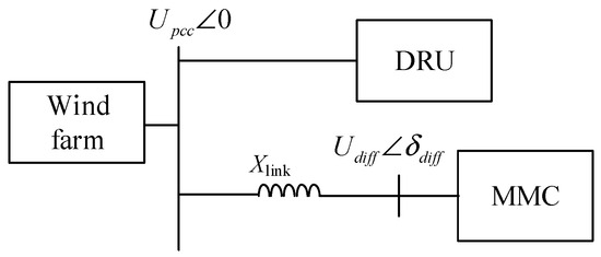
where Pdiff and Qdiff are the active and reactive power at the output port of the converter valves, is the phase angle of the AC voltage vector of the converter valves, and Upcc is the AC bus voltage of the wind farm. The simplified connection relationship between the MMC and the DRU is shown in Figure 2, where Xlink is the connecting reactance between the MMC and the AC bus, mainly including the bridge arm reactance of the MMC and the equivalent reactance of the transformer. The MMC needs to compensate for all the reactive power at the PCC point, which is shared by two MMCs operating in parallel, including the steady-state reactive power of the DRU (326 Mvar) and the reactive power of the submarine cable (18 Mvar, equivalent to a 3 km submarine cable).
Figure 2.
Single-line diagram of the wind farm transmission system.
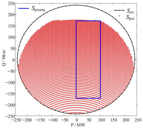
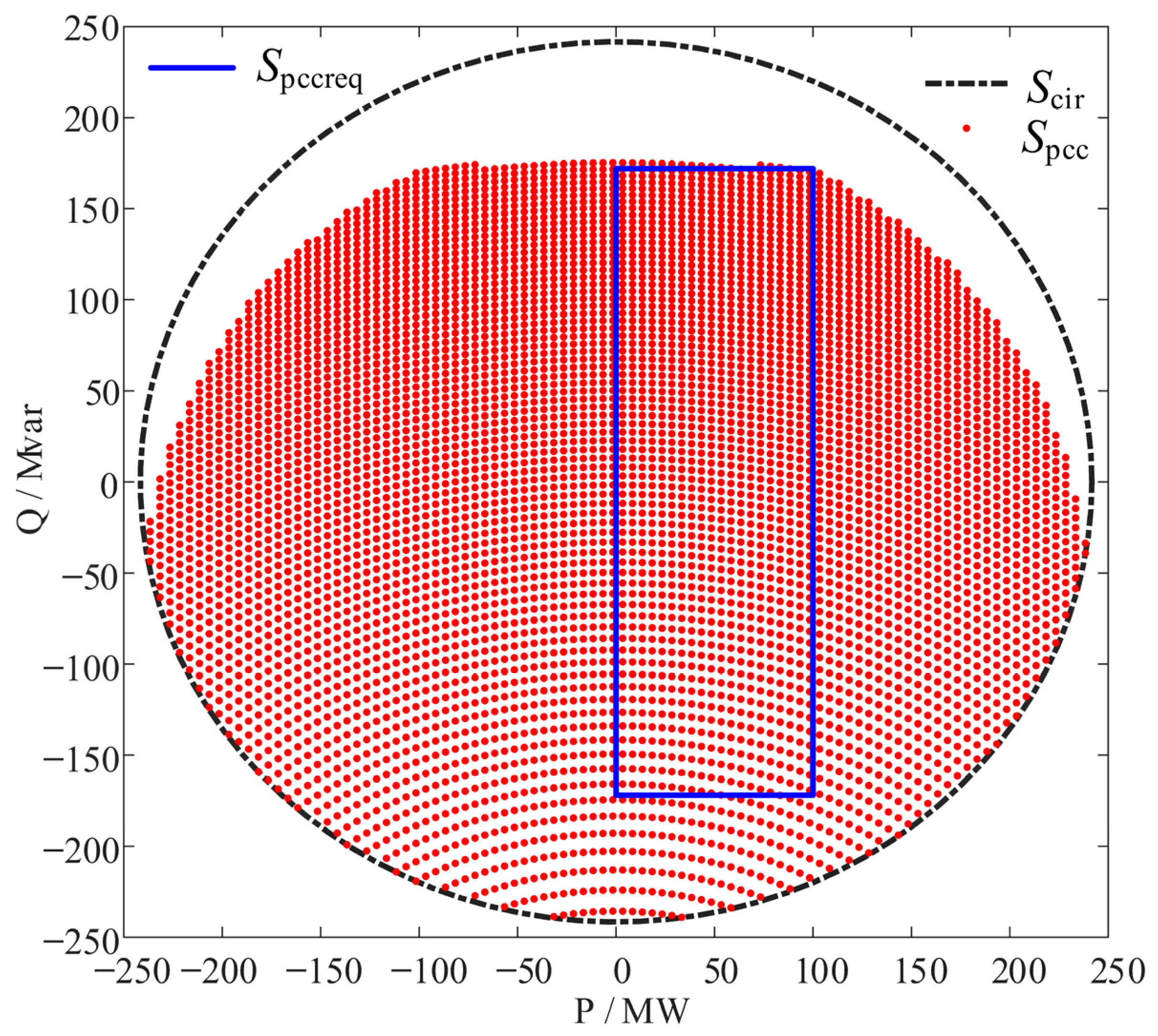
Based on preliminary calculations, the reactive power demand of the diode valves is relatively high. Therefore, two MMCs are connected in parallel and then in series with the DRU valves to reduce the current stress on the MMCs. The reactive and active power are equally shared between the two MMCs. Based on the above analysis, it is necessary to verify whether a single MMC has the capability to output 100 MW of active power and 172 Mvar of reactive power at the PCC point. Considering that the AC link reactance of the MMC consumes a certain amount of reactive power, setting the rated reactive power of the MMC to approximately 220 Mvar can cover the steady-state reactive power demand of the DRU valves and the submarine cable. The verification results are shown in Figure 3, where Scir is the power circle of the MMC’s rated operating range, Spcc is the power operating range of the MMC at the PCC point after passing through Xlink, and Spccreq is the power demand range at the PCC point.
Figure 3.
MMC-rated operating power range and wind farm AC bus reactive power demand range.
Once the MMC AC voltage is determined, the rated values of the AC current and the bridge arm current can be calculated. The charging and discharging of the MMC submodule capacitor depend on the switching function and the direction of the bridge arm current. The submodule capacitor voltage, bridge arm current, and switching function satisfy the relationship of Equation (11):
In the formula, Csm is the capacitance of the submodule capacitor, Uc is the submodule capacitor voltage, and iarm is the arm current. Taking the lower arm of any phase as an example, its average switching function is 1 + msin (ωt). Considering that the MMC circulating current suppression control is enabled and the double-frequency circulating current is neglected, the arm current contains a DC component and a fundamental frequency component, which can be expressed as Idc/3 + (Im*sin (ωt + φ))/2, where φ is the phase of the current. When the converter delivers full reactive power, the capacitor voltage fluctuation is maximum, and the voltage fluctuation rate is given by Equation (12),
where N is the number of submodules per arm. In engineering practice, the submodule capacitor voltage fluctuation is typically limited to approximately 10% of its rated value. Based on the above equation, the submodule capacitance can be preliminarily calculated as 11 mF.
The arm reactor is usually selected as 10% of the system base impedance, while also being adjusted according to the control and protection system delay and the turn-off capability of the main circuit devices. Based on the active and reactive power capacity requirements of the typical offshore wind farm transmission topology described above, the main circuit parameters of the MMC are presented in Table 2.
Table 2.
MMC parameters.
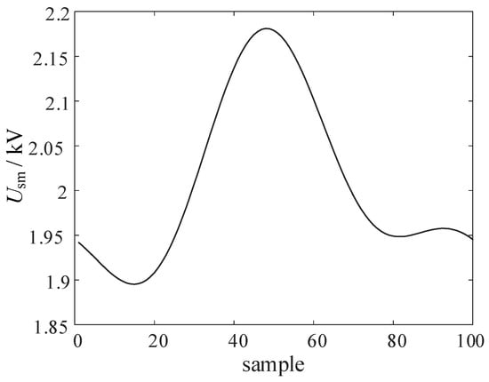
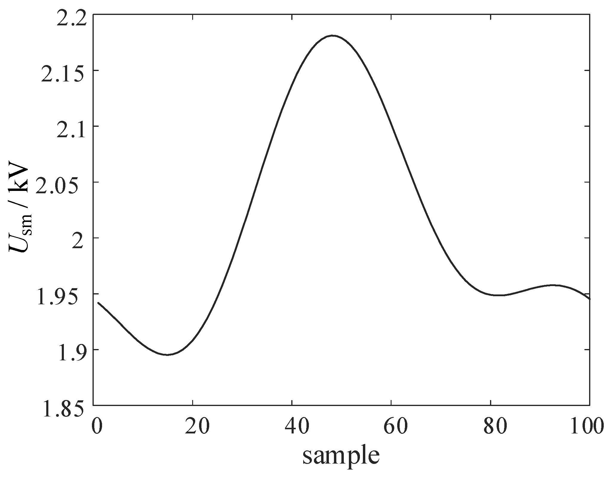
Further verify that during full-power operation, the submodule capacitor voltage fluctuation remains within the allowable range (typically required to be less than 10% of the rated voltage). Based on Equation (11), the numerical solution for the capacitor voltage fluctuation within one cycle under steady-state conditions is calculated, and the resulting submodule capacitor voltage fluctuation is obtained as shown in Figure 4. The fluctuation values of the capacitor voltage are calculated over one cycle of 20 ms, with 100 sampling points within one cycle, as shown in the range of the horizontal axis in Figure 4.
Figure 4.
Real-time values of MMC submodule capacitor voltage fluctuation within one cycle.
4. Hybrid Topology Control Strategy (Methods & Materials)
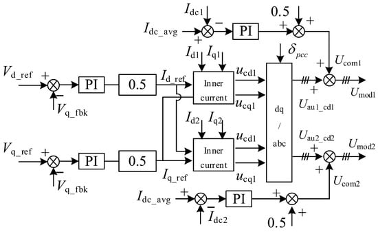
In the proposed topology mentioned above, the MMC adopts two parallel-connected groups, with the AC sides of the two converters connected in parallel to the same AC bus. Therefore, a common AC voltage outer loop is employed. To maintain power balance between the two parallel MMC groups, the current reference for each MMC is set to half of the total current. As shown in Figure 5, the output of the voltage outer loop consists of the dq-axis current references Idref and Iqref. The two MMC groups are each equipped with independent current inner loops, where Id1 and Iq1 are the dq-axis feedback quantities of the AC side current for MMC1, and Id2 and Iq2 are the dq-axis feedback quantities for MMC2. The current inner loop employs dq-axis current decoupling control based on PI regulators. The outputs of the current inner loops are the dq-axis modulation signals for MMC1 and MMC2, denoted as ucd1, ucq1, ucd2, and ucq2. Uau1~Ucd1 represent the AC components of the modulation signals for the six arms of MMC1, while Uau2~Ucd2 represent the AC components for MMC2. is the phase of the grid-side voltage vector, obtained from a phase-locked loop (PLL).
Figure 5.
Control structure of parallel MMCs in hybrid topology.
The DC sides of the two MMCs are connected in parallel. To suppress circulating currents between the two MMCs on the DC side, a DC current balancing control loop is designed. By adjusting the DC modulation indices of the MMCs, the DC output currents of the two converters are balanced. Idc_avg is the average value of the DC currents of MMC1 and MMC2, while Idc1 and Idc2 are the respective DC current feedback values. The DC modulation components Ucom1 and Ucom2 are obtained through PI regulators. The final bridge arm modulation signals Umod1 and Umod2 are generated by adding the respective DC modulation components and AC modulation components of MMC1 and MMC2. Multiplying by 0.5 in the figure is because the two MMCs are connected in parallel, so the AC current reference value for a single MMC should be half of the total AC current.
5. Results and Discussion
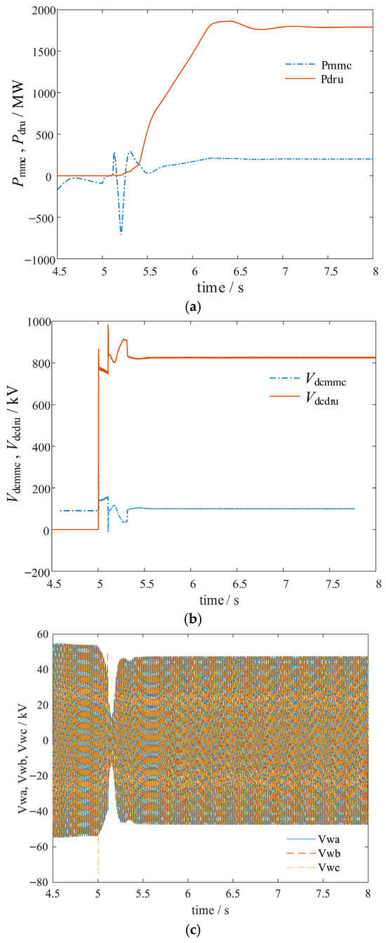
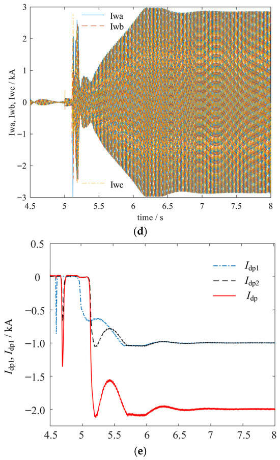
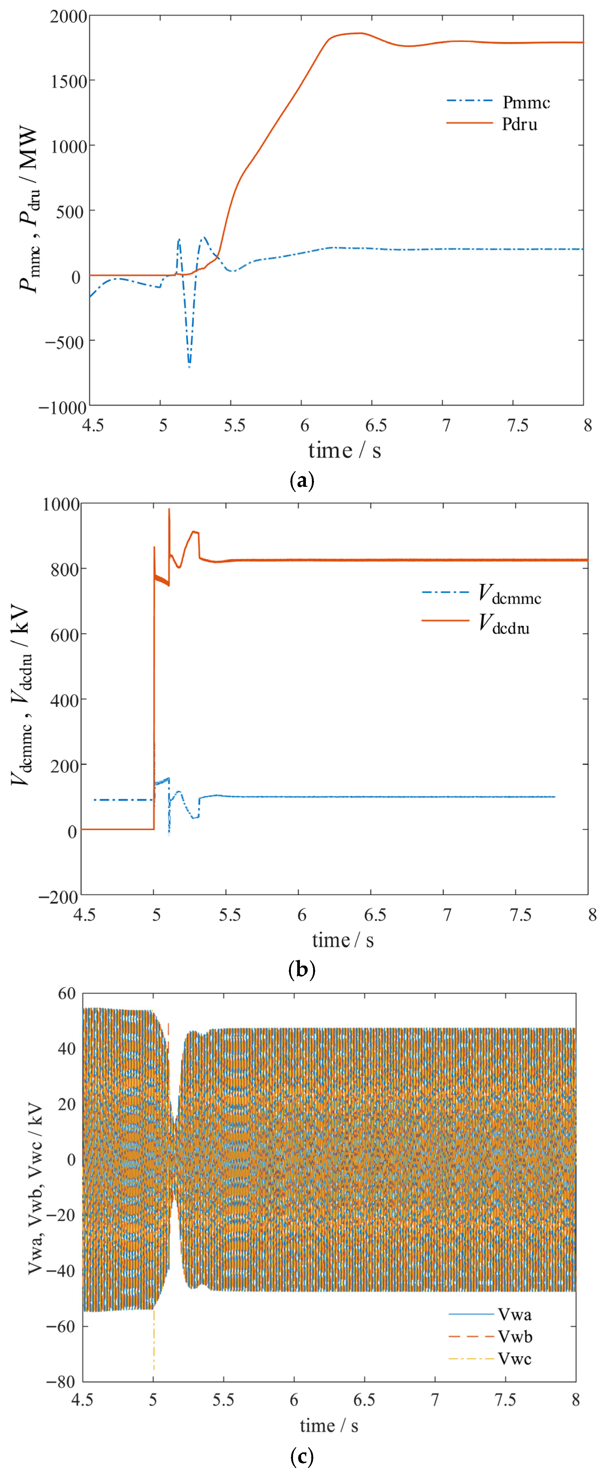
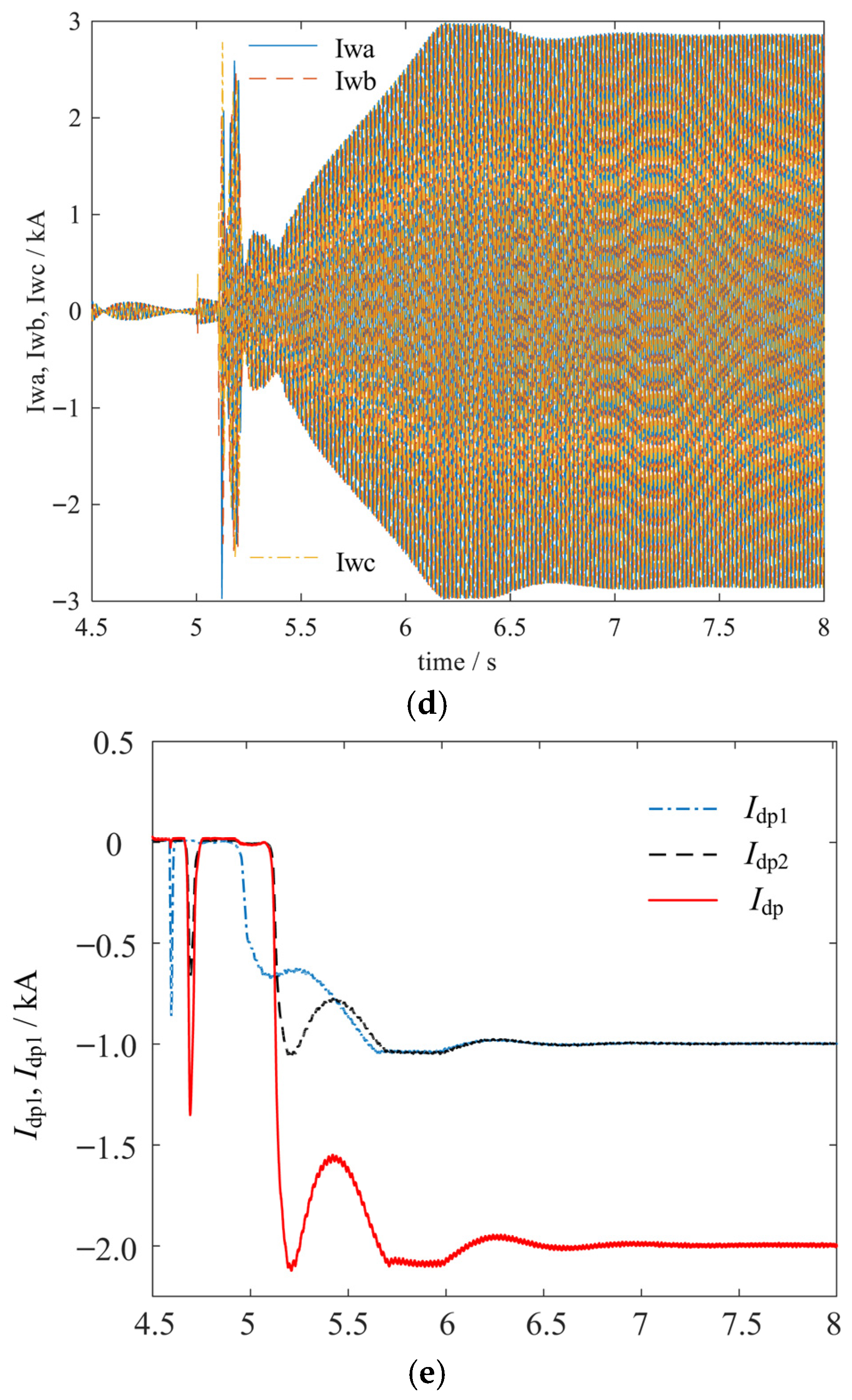
To verify the correctness of the aforementioned parameter design method, a simulation model of the converter valve with DRU and MMC connected in series is established based on PSCAD (version 4.6.2). The system has a rated capacity of 2000 MW, and the AC system voltage of the wind farm is 66 kV, which is connected to the AC sides of the DRU and MMC via transformers. The rated DC voltage of the MMC is 100 kV, and the rated DC voltage of the DRU valve is 900 kV. After the system reaches steady-state operation, the voltage ratio and transmission power of the DRU and MMC are verified to be largely consistent with the design objectives. Specifically, Figure 6a shows the active power of the DRU and MMC. Under steady-state conditions, the DRU outputs 1800 MW, and the MMC outputs 200 MW. Figure 6b presents the DC voltage on the valve side of the DRU and MMC, where the DC voltage ratio under steady-state is 1:9, consistent with the transmission power ratio. Figure 6c and Figure 6d depict the AC bus voltage and current of the wind farm, respectively. Under steady-state operation, the amplitude of the AC bus voltage of the wind farm tracks the given reference value, and the output current of the wind farm reaches the rated value. Figure 6e illustrates the positive DC bus current of the two parallel MMCs.
Figure 6.
Simulation results of hybrid converter valve in steady-state operation, (a) active power of DRU and MMC; (b) DC voltage of DRU and MMC; (c) AC bus voltage of the wind farm; (d) AC bus current of the wind farm; (e) DC current of MMC1 and MMC2.
Figure 6a,b show system achieving the designed 9:1 power split. This confirms that the DC voltage ratio of 1:9 directly translates to the desired power sharing, validating the relationship expressed in Equation (1). The close match between simulated and target values demonstrates the accuracy of the parameter design methodology. Under the action of the DC current balancing controller, the output DC currents of both MMCs are equal under steady-state conditions. Figure 6c and Figure 6d depict the AC bus voltage and current of the wind farm, respectively. Under steady-state operation, the AC bus voltage amplitude accurately tracks the given reference value (66 kV), and the output current reaches the rated value (17.5 kA for a 2000 MW system at 66 kV). This confirms that the MMC’s grid-forming control effectively establishes and regulates the AC voltage, while the wind farm injects full power into the hybrid converter. From Figure 6e, the simulation results indicate that 90% of the wind farm’s power is transmitted through the DRU valve, significantly reducing the capacity and volume of the MMC. The MMC adopts a parallel structure to match the current-carrying capacity of the DRU, and an additional current-sharing control outer loop is incorporated to achieve balanced output power of the MMC.
Collectively, these simulation results verify that 90% of the wind farm’s power is transmitted through the DRU valve, significantly reducing the required capacity and volume of the MMC. The parallel MMC structure effectively matches the current-carrying capacity of the DRU, and the proposed control strategy ensures stable and balanced operation. All key electrical quantities align with the design targets, confirming the correctness of the parameter design method presented in Section 3.
6. Conclusions
For offshore wind farm integration via VSC-HVDC systems, the adoption of a hybrid topology with DRU and MMC connected in series at the offshore converter station can reduce the volume and weight of the offshore converter valves. Based on the designed DC voltage ratio between the DRU and MMC, their respective rated active powers are determined. The reactive power operating range of the MMC valves is established according to the sum of the steady-state reactive power of the DRU and the submarine cable, from which the detailed parameters of the converter valves can be further calculated. The MMC employs a valve-bank parallel topology to further enhance its current-carrying capability and transmission capacity, achieving power balance among the parallel MMCs through AC and DC side current-sharing control.
The hybrid topology at the offshore station is coordinately controlled with the full-bridge and half-bridge hybrid valve groups at the onshore station. The onshore station operates at a reduced voltage, while the offshore station MMC is connected to the DC bus to realize the black start of the offshore wind farm. Upon completion of the startup, the DRU is then connected to the DC bus to achieve full-power transmission. Simulation results verify that the electrical quantities of the converter valves during steady-state operation are largely consistent with the designed values. The parameter calculation and control methods proposed for this hybrid topology converter valves can be applied to the design of lightweight converter valves. The experimental validation of the proposed topology, including a downscaled laboratory prototype, experimental verification constitutes future work.
Author Contributions
Conceptualization, J.W.; Formal analysis, J.W.; original draft preparation, writing, J.W.; Resources, C.L.; software, C.L. and Y.Z.; Validation, J.L. and Y.Z.; writing—review and editing, J.L. All authors have read and agreed to the published version of the manuscript.
Funding
This research received no external funding.
Data Availability Statement
The original contributions presented in this study are included in the article. Further inquiries can be directed to the corresponding author.
Conflicts of Interest
Author Ye Zhang was employed by the company Rongxin Huiko Electric Co., Ltd. The remaining authors declare that the research was conducted in the absence of any commercial or financial relationships that could be construed as a potential conflict of interest.
References
- Wang, C.; Shao, B.; Xie, B.; Zhang, J.; Yin, K.; Zhang, G. A New Topology and Its Control Strategy of Hybrid Rectifier Valve for Large-scale Offshore Wind Power DC Transmission. High Volt. Eng. 2023, 49, 4642–4653. Available online: https://kns.cnki.net/kcms2/article/abstract?v=mDcNmAOuO1M-a63wy9WoWB-HE1k48BMcH4EG9YrMacPh70-N2kSzkUF_3uFhA-lK9S7ANraTueu-Iac2AyrFx28u_jFDW5OsR2anRfNYdH3gnIaadVuIadI22IORgMywm9CY2YXlyMRC_ZG1JJM_Te9EzWptOxj3xOz34gA92LI=&uniplatform=NZKPT (accessed on 25 March 2026).
- Zhang, G.; Xiang, W.; Chen, X.; Wen, J. Capacity Design of Cascaded Diode Rectifier-MMC Based HVDC for Offshore Wind Farm Integration. IEEE Trans. Power Deliv. 2024, 39, 2908–2919. [Google Scholar] [CrossRef] [Scilit]
- Xiao, H.; Gan, H.; Dong, Y.; Huang, Y.; Liu, Y. Control and Capacity Design of Station-Hybrid HVDC System with DRU and MMC in Parallel for Offshore Wind Power Integration. IEEE Trans. Power Deliv. 2024, 39, 1783–1793. [Google Scholar] [CrossRef] [Scilit]
- Gan, H.; Xiao, H.; Huang, Y. Control Strategy and Capacity Selection of DRU-MMC Hybrid Converters for Offshore Wind Power. Autom. Electr. Power Syst. 2024, 48, 28–36. [Google Scholar]
- Chen, L.; Wang, J.; Li, Z.; Guo, C.; Zhang, B.; Li, Z. Steady-State Analysis of the DR-MMC Based Hybrid Topology for Offshore Wind Power Transmission. IEEE Trans. Power Electron. 2024, 40, 3177–3188. [Google Scholar] [CrossRef] [Scilit]
- Li, Z.; Yang, R.; Fang, Z.; Yu, H.; Cai, X. Research on Commutation Mechanism and Harmonic Suppression of Offshore Wind Farm Integration with DRU-VSC Hybrid Transmission System. In Proceedings of the CSEE, Nanjing, China, 21–23 February 2025; Volume 45, pp. 3958–3972. Available online: https://kns.cnki.net/kcms2/article/abstract?v=mDcNmAOuO1NE_7mfieYfTIGuz3v9s-lIktiPKTzsdKxOQNcTr_k2TgrGNFjUb9pyVRicn644Z2lb0jy2epDsa3bTZA1CAJ-D-MAul-ZFznAm26uI3i1R9-LSU5Xvcqjx5RwAyywvuLB4WSe6zkwQO1f1CRsIBS0os1tAua1cpUc=&uniplatform=NZKPT (accessed on 25 March 2026).
- Zhang, G.; Xiang, W.; Wen, J. Impedance Modeling and Stability Analysis of DR-MMC Based Hybrid HVDC for Offshore Wind Farm Integration. IEEE Trans. Power Deliv. 2023, 38, 4397–4409. [Google Scholar] [CrossRef] [Scilit]
- Yu, Z.; Song, Q.; Zhang, P.; Zhao, B.; Liu, W.; Wang, K. Startup Strategy Based on Coordinated Energy Balance Method of Series-Connected Hybrid Diode Rectifier for Integrating Offshore Wind Farm. In Proceedings of the IECON 2024—50th Annual Conference of the IEEE Industrial Electronics Society, Chicago, IL, USA, 3–6 November 2024. [Google Scholar]
- Peng, K.; Zhou, G.; Li, W.; Jin, Y.; Zhang, Z.; Xu, Z. Hybrid Offshore Wind Power Delivery Scheme Using Diode Rectifier Unit and Modular Multilevel Converter. High Volt. Appar. 2023, 59, 166–175. Available online: https://kns.cnki.net/kcms2/article/abstract?v=mDcNmAOuO1O-BksioOtPN3xiVvctgVW49C-lU6lq42IWgealILrEUQsPkvo3WadcEOKyazC7SodVDYdvJnw-ogjA6LcLQ5QudlM1cck9h7okwyk0Tk2mraEuJL3kfE0DLy_et3HQbr5QsFJU1CyJtVAkZ85RK8YAz8CVonTGRdw=&uniplatform=NZKPT (accessed on 25 March 2026). [CrossRef]
- Tian, S.; Campos-Gaona, D.; Lacerda, V.A.; Torres-Olguin, R.E.; Anaya-Lara, O. Novel Control Approach for a Hybrid Grid-Forming HVDC Offshore Transmission System. Energies 2020, 13, 1681. [Google Scholar] [CrossRef] [Scilit]
- Wu, Y.; Zhang, L.; Zhou, Y.; Hu, Z.; Zhao, X.; Zhuang, Q. A hybrid HVDC converter based on MMC and diode rectifier for offshore wind farm integration. In Proceedings of the 2021 International Conference on Power System Technology (POWERCON), Haikou, China, 8–9 December 2021; pp. 1476–1480. [Google Scholar] [CrossRef] [Scilit]
- Huang, Y.; Huang, X.; Xiao, H.; Liu, T. Black Start Strategy of Diode Rectifier Unit Based Flexible Low-frequency Transmission System for Offshore Wind Power. High Volt. Eng. 2025, 51, 346–355. Available online: https://kns.cnki.net/kcms2/article/abstract?v=mDcNmAOuO1O8_XZumrkAPn8GH959gAqgtXa8BZ_cqOVX9we_i_bac27gYC2-rbjMu6esk2Mj85A_BwfiH7rjg5D6VZsBBg2bSXfEykMjNTASJG57NtNhgR9Ldln5nI-ZEcHwltlc7uhV70HrK9QcHwSpZ0VBjBN97qWwCLClAGw=&uniplatform=NZKPT (accessed on 25 March 2026).
- Yuan, Q.; Xie, Y.; Jiang, T.; Duan, J. Control Strategies of DRU + MMC Hybrid Converter at the Sending End with Compatibility of Grid-following and Grid-forming Offshore Wind Farm Transmission. Power Syst. Technol. 2024, 48, 4482–4492. Available online: https://kns.cnki.net/kcms2/article/abstract?v=mDcNmAOuO1OE626ZSX86dAJYifa4V1mXGka6fJ-spwsMae154-aKxtXqkZTbCRU-0ZI8vydqUJEp4zMxIrCPw564xiC-R-1pUtqDe8VBUEzeyKvfocY68lR362GjOwz9TtRxbgTVNluBGujsatQ2RGJq66bvoxd4iFFfh8kPVVE=&uniplatform=NZKPT (accessed on 25 March 2026).
- Xie, Y.; Yuan, Q.; Duan, J.; Jiang, T. Remote Offshore Wind Power Transmission Scheme Based on Diode Rectifier Unit and Modular Multilevel Converter with Black-start and Grid-forming Capability. Autom. Electr. Power Syst. 2024, 48, 142–152. Available online: https://kns.cnki.net/kcms2/article/abstract?v=mDcNmAOuO1PhiEc6Aj9tUoPqN6bxFDu5_HfqIVFG9Ublh7xWczMfq4ISmYaJsJ5IqUo0u4KFqZWZcbWG00Xx4HyliZOtvXuN5tQcoTkU2JW5Uc3BZbS-xM4NOtFvJzNuikZCvFpIjgPqAkUa1RfxFq9qJAX-8RdFT4dQXHfORG0=&uniplatform=NZKPT (accessed on 25 March 2026).
- Li, R.; Yu, L.; Xu, L.; Adam, G.P. Coordinated Control of Parallel DR-HVDC and MMC-HVDC Systems for Offshore Wind Energy Transmission. IEEE J. Emerg. Sel. Top. Power Electron. 2020, 8, 2572–2582. [Google Scholar] [CrossRef] [Scilit]
- Jin, Y.; Zhang, Z.; Wu, H.; Pei, X.; Chen, J.; Xu, Z. Black Start Strategy of Offshore Wind Farm Based on Grid-forming Wind Turbines and Diode Rectifier Unit. High Volt. Eng. 2023, 49, 3730–3740. Available online: https://kns.cnki.net/kcms2/article/abstract?v=mDcNmAOuO1OD28HscKRj2GPtlfAj7tWZDDBwBUR9eGLB0UmRf4TGiai6wdOWP8Cr9enygTZx4EEoRcjWBfNmlw5NKz71Yb4yYuEUT7P-WdjLZoeZPgr7D20Uv_xeozXvKMWA_tuC3FKBH_s1-LgR5buM1XUFgNR-2Dbja-Jbkk8=&uniplatform=NZKPT (accessed on 25 March 2026).
- Di, S.; Xiang, W.; Xu, Y.; Meng, P.; Zhang, H.; Wen, J. Research on Topology and Control Strategy of DR-MMC Cascaded Hybrid HVDC Transmission System for Offshore Wind Power. In Proceedings of the 2023 International Conference on Power System Technology (PowerCon), Jinan, China, 6 December 2023. [Google Scholar]
- Yu, L.; Wang, Z.; Zhu, J.; Tong, W.; Li, R. Capacity Configuration of Grid-forming-Grid following Wind Turbines in Diode Rectifier Unit-High Voltage DC Offshore Wind Power Transmission System. Autom. Electr. Power Syst. 2025, 49, 44–55. Available online: https://kns.cnki.net/kcms2/article/abstract?v=mDcNmAOuO1N6NIi0oNVWGqSruhkOvHT4XP69LPavxb97sNC9nzMEWqF-Vt9Kz3MK9JywnHTD80-2HOaPRizQPCqyOPbphTfQWcLoMRVABbBS6L_nQjALoM_eU8rHeIoRkvgrtmJNOd3T1d3xHcxBdAR51_JmiGnepTFYD7eVOq4=&uniplatform=NZKPT (accessed on 25 March 2026).
- Yu, H.; Cai, X.; Yang, R.; Yang, M.; Tang, G. Analysis of Electrical Regulation Characteristics and Group Grid-forming Control Strategy of DRU-HVDC Integrated Offshore Wind Farm. In Proceedings of the CSEE, Nanjing, China, 21–23 February 2025; Volume 45, pp. 2318–2334. Available online: https://kns.cnki.net/kcms2/article/abstract?v=mDcNmAOuO1MdkwdVM9xhZSSKVqBlNWZ5sYxNthta8OqkklBmTLR61gk4SxoZ439-enY64ABFLGcjqmLibe_KjYpSXBfy4H7y8NH4J5lQ3EWtiTDBYyFo5BvIcr72y1fB3YVGNa3TtG0gZs1gtkjL6wV0qKwcVABBsnORHlKiULQ=&uniplatform=NZKPT (accessed on 25 March 2026).
- Sun, Y.; Kong, D.; Zhang, Z.; Wang, Y.; Pei, Z.; Zhu, D.; Heldwein, M.L. Consensus-Based Distributed Control of Offshore Wind Farms Connected via DR-HVDC. IEEE Trans. Ind. Electron. 2025, 72, 5936–5947. [Google Scholar] [CrossRef] [Scilit]
- Sun, Y.; Kong, D.; Zhang, Z.; Wang, Y.; He, H.; Heldwein, M.L. Decoupled Distributed Control of Offshore Wind Farms Connected to DR-HVDC Based on Novel Adaptive Virtual Impedance. IEEE Trans. Power Electron. 2024, 39, 15242–15256. [Google Scholar] [CrossRef] [Scilit]
- Wang, K.; Song, Q.; Zhao, B.; Yu, Z.; Zeng, R. Grid-Forming Control of Offshore Wind Farms Connected with Diode-Based HVdc Links Based on Remote Active Power Regulation. IEEE Trans. Sustain. Energy 2024, 15, 1315–1327. [Google Scholar] [CrossRef] [Scilit]
- Zhang, G.; Xiang, W.; Chen, X.; Tu, R.; Qiao, X.; Wen, J. Grid-Forming Control Based on Adaptive Reactive Power Allocation for Offshore Wind Farms Connected to Diode-rectifier-based HVDC System. J. Mod. Power Syst. Clean Energy 2025, 13, 154–166. [Google Scholar] [CrossRef] [Scilit]
- Jin, Y.; Zhang, Z.; Xu, Z. Proportion of Grid-forming Wind Turbines in Hybrid GFM-GFL Offshore Wind Farms Integrated with Diode Rectifier Unit Based HVDC System. J. Mod. Power Syst. Clean Energy 2025, 13, 87–101. [Google Scholar] [CrossRef] [Scilit]
- Nami, A.; Rodriguez-Amenedo, J.L.; Arnaltes, S.; Cardiel-Álvarez, M.Á.; Baraciarte, R.A. Control of the Parallel Operation of DR-HVDC and VSC-HVDC for Offshore Wind Power Transmission. IEEE Trans. Power Deliv. 2022, 37, 1682–1691. [Google Scholar] [CrossRef] [Scilit]
- Yan, J.; Pan, P.; Wang, S.; Wang, S.; Li, T. Topology and Control Strategy of Offshore Wind Power via DR-MMC Parallel Hybrid DC Delivery System. In Proceedings of the 2024 6th Asia Energy and Electrical Engineering Symposium (AEEES), Chengdu, China; IEEE: New York, NY, USA, 2024; pp. 1–6. [Google Scholar]
- Li, F.; Chen, D.; Chen, H.; Luo, S.; Yu, H.; Hou, T.; Wang, G.; Huang, Y. Black-Start Strategy for Offshore Wind Power Delivery System Based on Series-Connected DRU-MMC Hybrid Converter. Electronics 2025, 14, 2543. [Google Scholar] [CrossRef] [Scilit]
- Wang, Y.; Tang, B.; Chang, Y.; Wang, C.; Li, Z. Black-Start and Frequency Response Control Strategies for Offshore Wind Power Transmitted by DR-MMC Series-Connected HVDC System. In Proceedings of the 2024 9th Asia Conference on Power and Electrical Engineering (ACPEE), Shanghai, China, 11–13 April 2024; pp. 2640–2646. [Google Scholar] [CrossRef] [Scilit]
- Zhang, H.; Hu, S.; Luo, L.; Lin, J.; Zhao, L.; Zhang, Z. A New Shunt Capacitor-Commutated Converter for Reducing Commutation Failure Probability of HVDC Transmission and Converter Transformer Noise. IEEE Access 2025, 13, 19650–19663. [Google Scholar] [CrossRef] [Scilit]

Disclaimer/Publisher’s Note: The statements, opinions and data contained in all publications are solely those of the individual author(s) and contributor(s) and not of MDPI and/or the editor(s). MDPI and/or the editor(s) disclaim responsibility for any injury to people or property resulting from any ideas, methods, instructions or products referred to in the content. |
© 2026 by the authors. Licensee MDPI, Basel, Switzerland. This article is an open access article distributed under the terms and conditions of the Creative Commons Attribution (CC BY) license.