


Abstract
In low-voltage-input, high-voltage-output applications, the input-parallel output-series (IPOS) LLC resonant converter experiences voltage and current imbalances due to parameter mismatches in resonant tank components. To address this issue, a self-balancing IPOS LLC resonant converter based on a shared inductance–capacitance (shared L-C) network is proposed. This topology achieves passive voltage and current self-equalization with an interconnection network of resonant inductors and capacitors between modules that does not need additional active components or complex control strategies. An analytical model based on the fundamental harmonic approximation (FHA) is developed to quantitatively assess the balancing performance, and a comparison is made with traditional structures and IPOS structures with only shared inductance. A 1.25 kW two-phase LLC resonant converter prototype is built for experimental validation. The results demonstrate that the balancing errors of the traditional structure and the shared inductance structure reach up to 25.43% and 17.63%, respectively, whereas the proposed structure significantly reduces the balancing error to only 0.43%. This study confirms that this structure provides a simple and reliable solution for voltage and current equalization in high-gain DC–DC conversion systems.
1. Introduction
Many high-output-voltage applications, such as large-capacity photovoltaic power generation for DC transmission and offshore wind power delivery, require the conversion of low-voltage input to high-voltage output [1,2]. In these scenarios, the higher input current and output voltage exacerbate the current and voltage stress on devices [3].
The input-parallel output-series (IPOS) LLC resonant converter with multiple modules is an effective solution to the aforementioned issues [4,5,6,7]. This topology not only significantly reduces the voltage and current stress on power devices but also enhances the system’s output voltage level and power capacity. However, in practical applications, the LLC converter based on the IPOS topology is prone to imbalances in output voltage and input current due to unavoidable manufacturing discrepancies in the resonant tank components of each module. These imbalances can adversely affect the device’s heat dissipation, shorten its lifespan, and, in severe cases, lead to module damage due to overvoltage and overcurrent stress, threatening the overall stability of the power conversion system [8]. Consequently, the issue of output voltage equalization and input current sharing in IPOS-based LLC resonant converters has become a focal point of attention in both academia and industry.
A substantial amount of research has been conducted on the issue of voltage equalization and current sharing in IPOS-based LLC resonant converters. The core idea is to achieve impedance matching between phases. These research approaches can be broadly classified into two categories: active and passive methods [9].
In active voltage equalization and current-sharing schemes, reference [10] proposes a maximum voltage equalization method that adjusts the voltage of each module by regulating the maximum output voltage, but this requires additional signal cascading and isolation. Researchers [11] employed droop control to ensure power balance, though the control is complex, and voltage fluctuations may occur in the event of a failure in the main module. Authors [12] implemented dual-loop control to achieve output voltage equalization at the series output of the IPOS converter, but it increases the number of components and sampling circuits, thereby raising costs and complexity. Others [13,14] regulated voltage gain using methods such as phase-shift control by sampling current to achieve voltage equalization and current sharing.
In passive voltage equalization and current-sharing schemes, Reference [15] proposes a coupled transformer scheme that reduces the magnetic core size and achieves output voltage balance through flux cancellation. However, the transformer design is complex, and it places high demands on core materials and flux control, which increase the system’s cost and design difficulty. Reference [16] proposes paralleling two-phase resonant inductors to achieve automatic voltage equalization, but, under multi-resonant parameter mismatches, the effectiveness remains suboptimal.
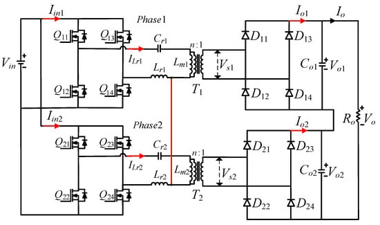
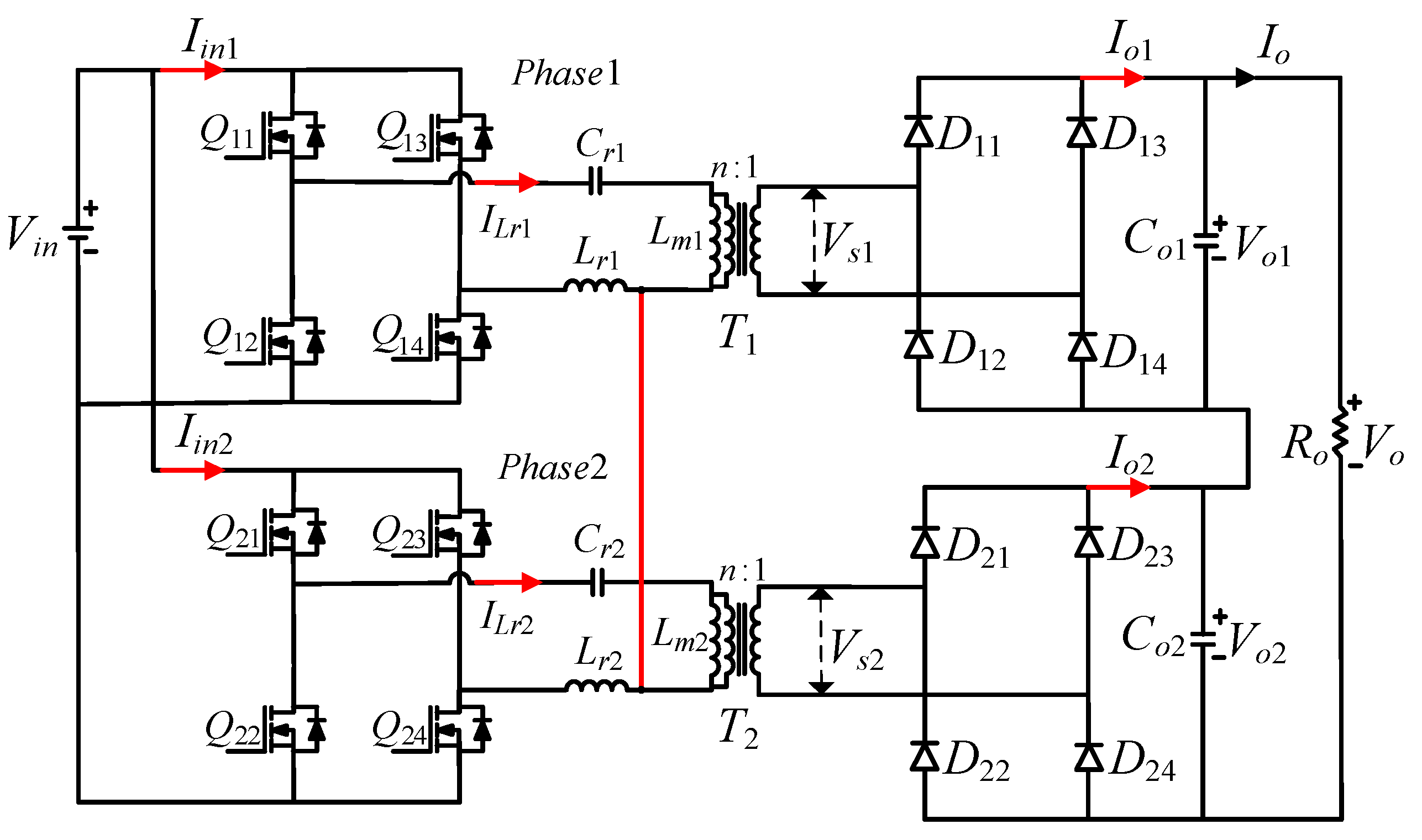
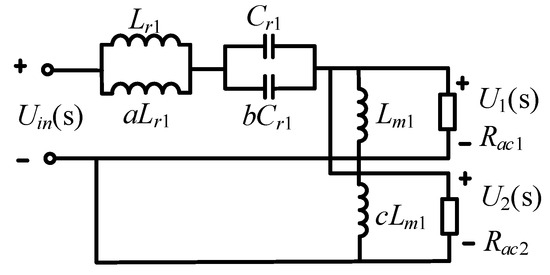
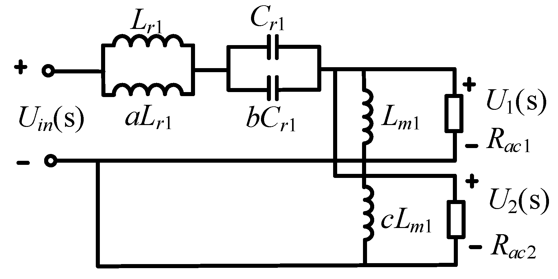
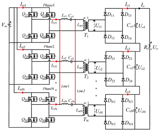
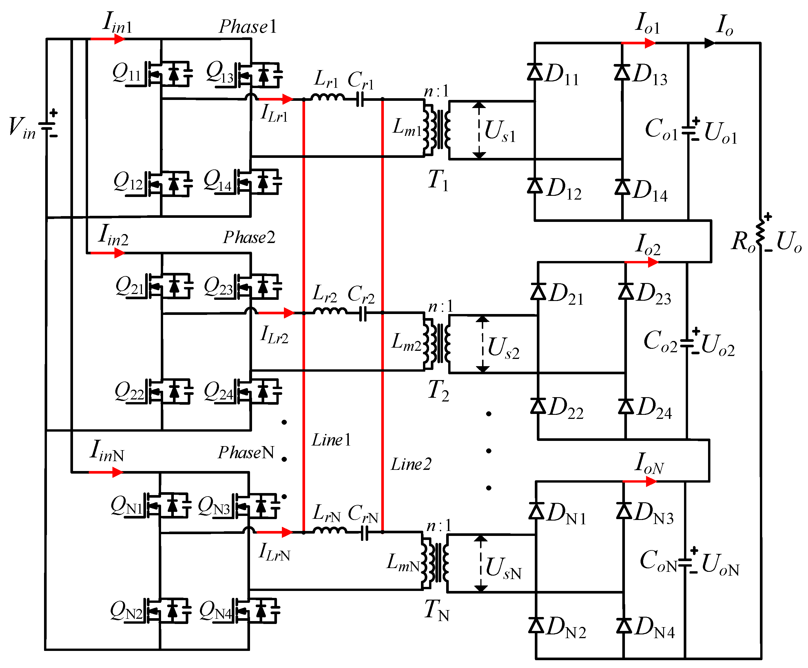
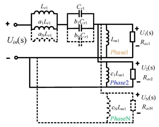
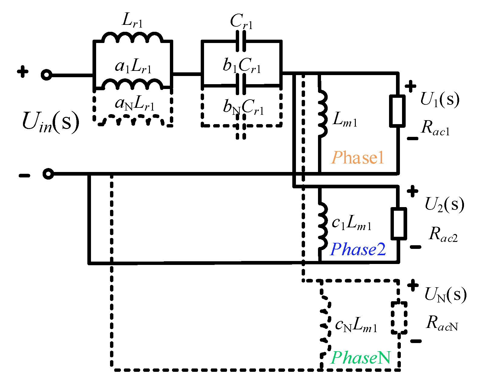
To address the aforementioned issues, this paper proposes a shared inductance–capacitance LLC resonant IPOS converter. This method connects the resonant inductors and resonant capacitors of each phase of the LLC resonant converter in parallel through interconnection lines, achieving precise voltage equalization across all phases and input current sharing over the entire load range.
The sections of this paper are arranged as follows:
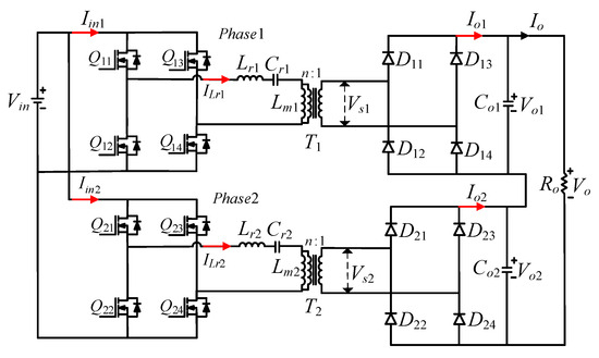
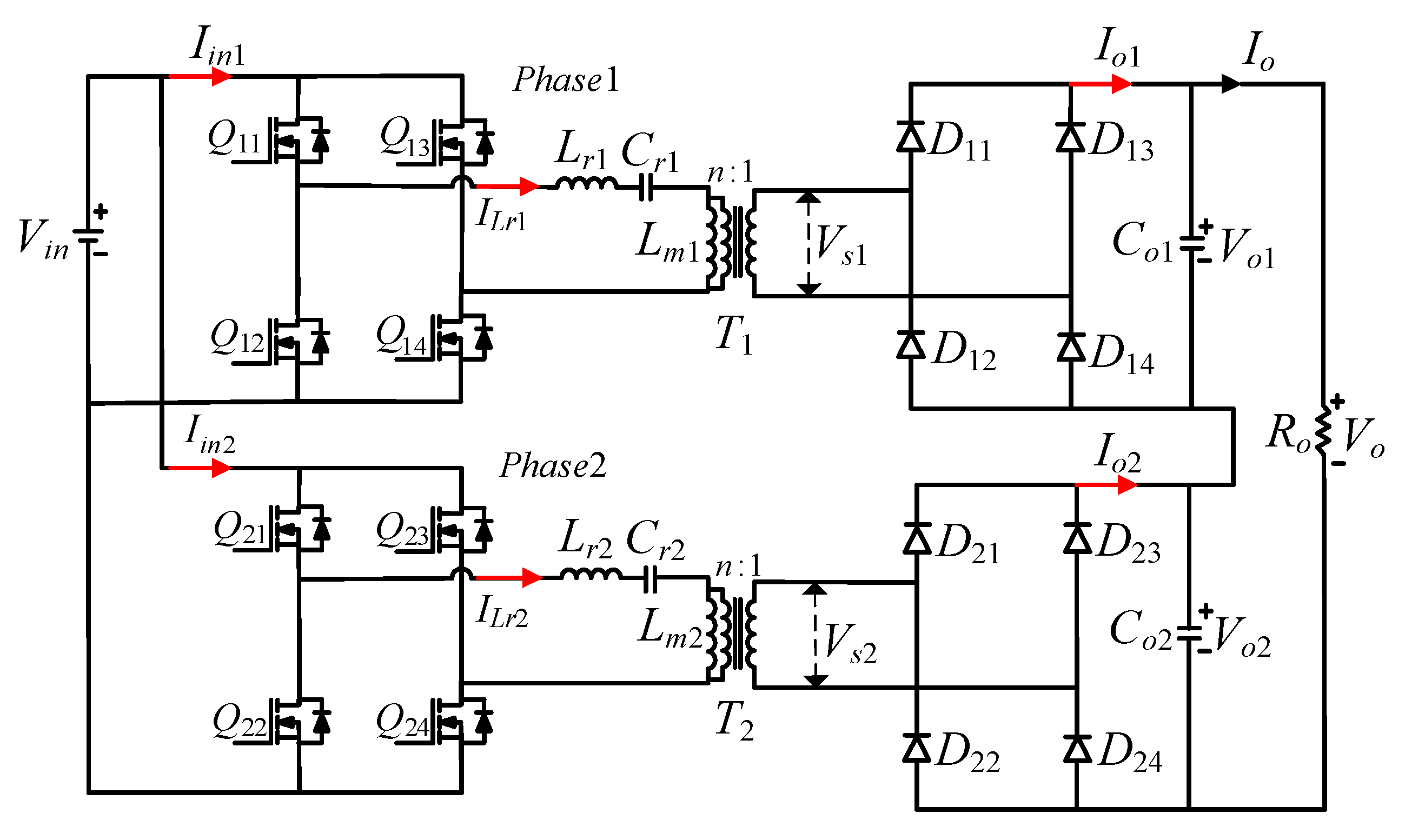
Section 2 reviews and analyzes the limitations of the traditional IPOS-type LLC resonant converter and the shared inductance structure. Section 3 introduces in detail the voltage and current equalization principles and advantages of the proposed shared inductance–capacitance structure in the IPOS-type LLC converter and discusses the module expansion capabilities. Section 4 analyzes the voltage and current equalization performance of the proposed method considering parasitic parameter mismatches. Section 5 validates the effectiveness of the proposed method through simulations. Section 6 develops a 1.25 kW two-phase experimental prototype and builds a testing platform, comparing it with traditional structures and the shared inductance structure to verify the effectiveness and superiority of the proposed topology. Section 7 summarizes this research and describes future research directions.
4. Voltage and Current Equalization Performance of Proposed Structure Considering Parasitic Parameter Mismatches
4.1. Voltage Equalization Analysis of Proposed Structure
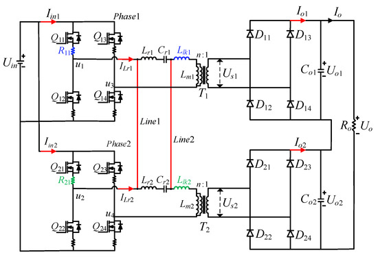
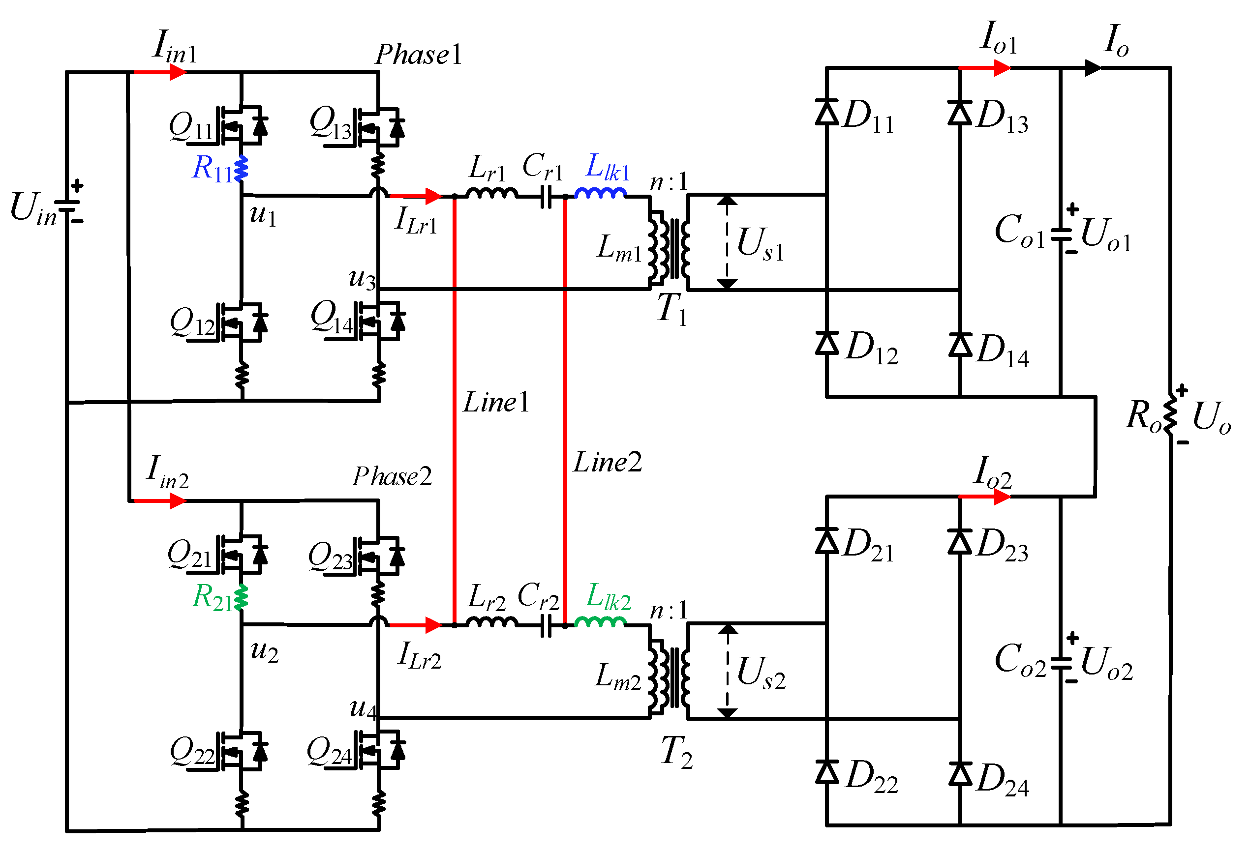
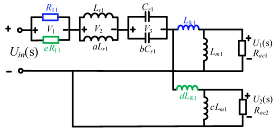
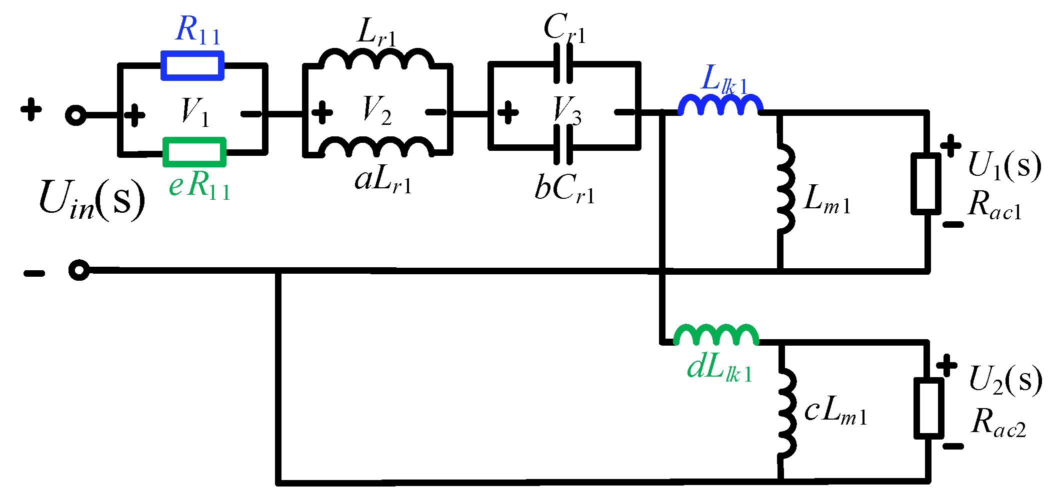
In practical applications, for multi-phase series-parallel LLC resonant converters, in addition to mismatches in resonant inductance, resonant capacitance, and magnetizing inductance, there are also mismatches in other parasitic parameters. These mismatches mainly include leakage inductance and the on-resistance of the power switches. Regarding the selection of parasitic parameters, reference is made to [17]. Nevertheless, a distinct topological configuration was adopted in this study compared to the aforementioned literature, specifically an IPOS-type full-bridge topology, whose detailed circuit schematic is illustrated in Figure 12.
Figure 12.
Detailed circuit of the proposed method considering parasitic parameters. Modified from [17].
Llk1 and Llk2 represent the leakage inductances of phase 1 and phase 2, respectively; R11 and R21 are the on-resistance of the upper switch of the two-phase modules. The parameter mismatches of the two-phase modules in Figure 12 are defined in (19), where a, b, c, d and e are used to indicate the parameter mismatches of the two-phase LLC converter.
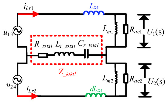
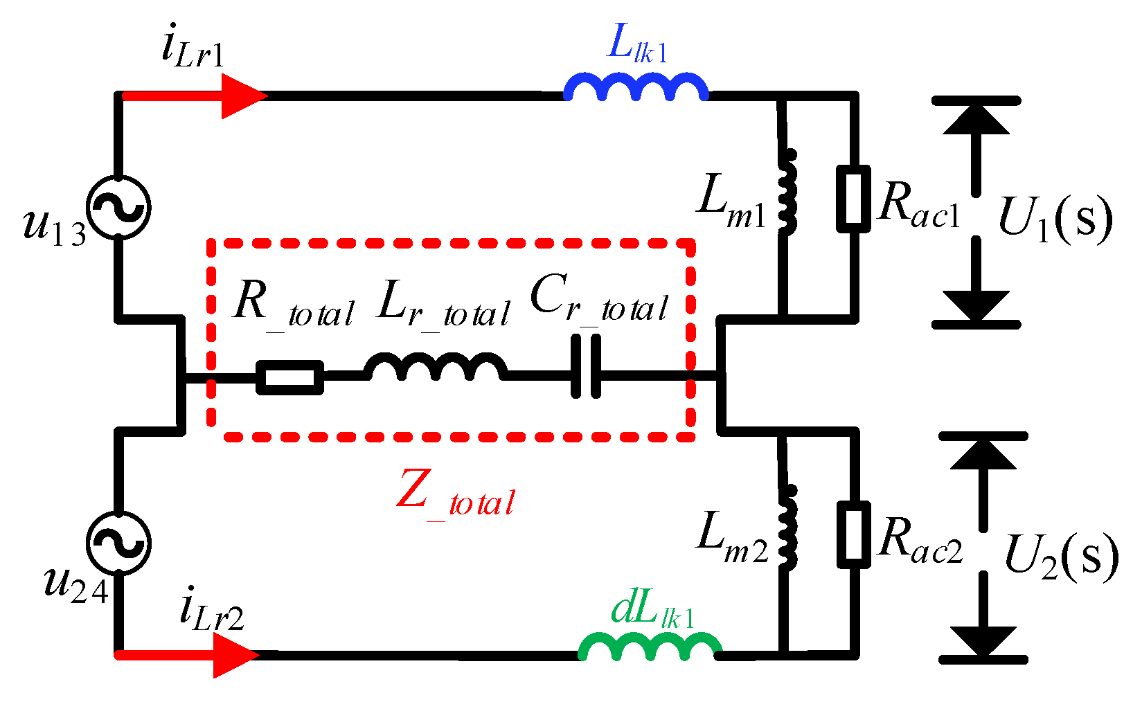
The equivalent circuit of the proposed structure based on FHA with parasitic parameters is shown in Figure 13.
Figure 13.
Fundamental harmonic equivalent circuit considering parasitic parameters.
As shown in Figure 13, due to the interconnection lines, the on-resistance, resonant inductance, and resonant capacitance of the two modules are connected in parallel. The impedance divider relationship between U1(s) and U2(s) is expressed in Equation (20).
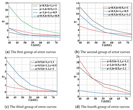
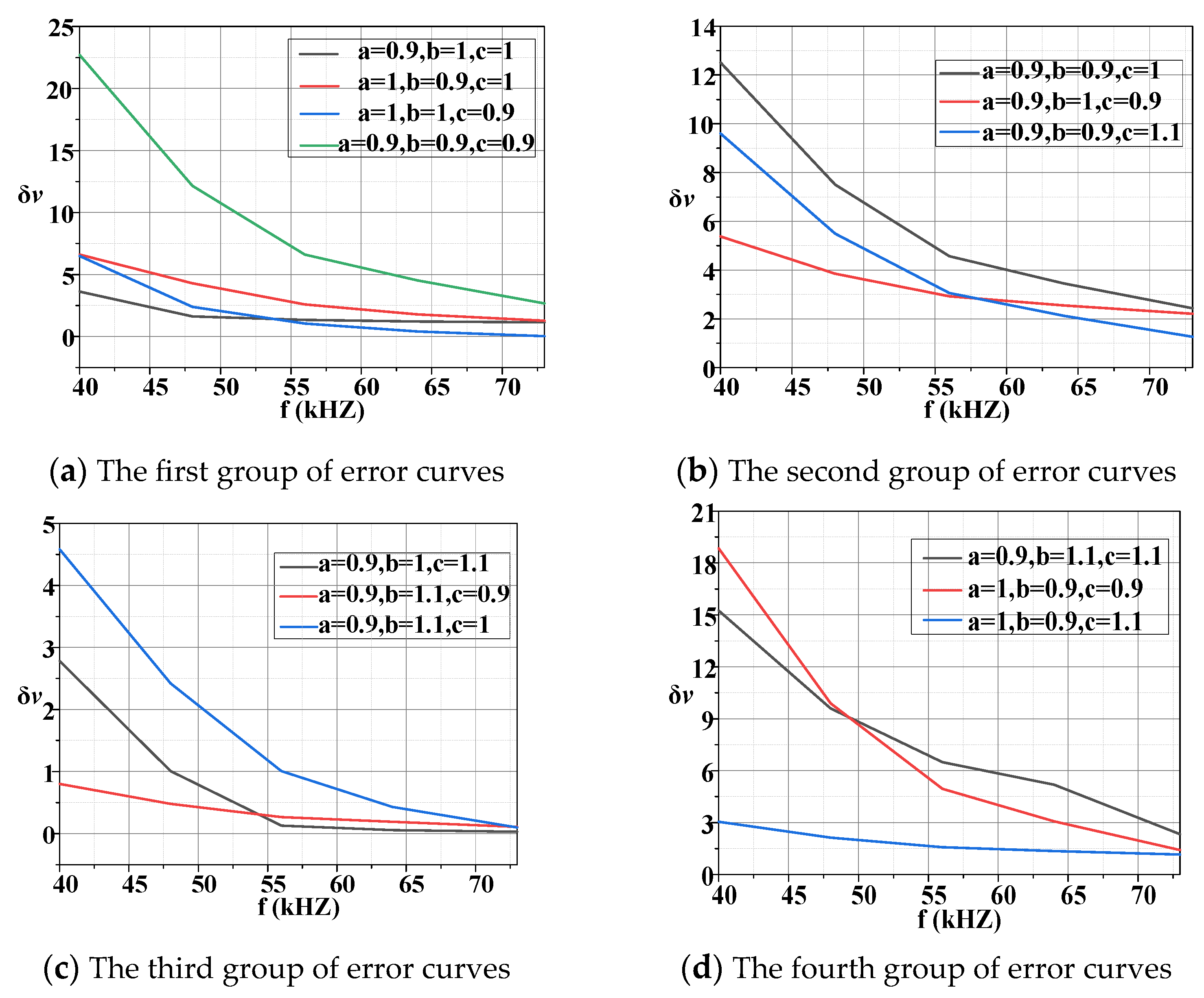
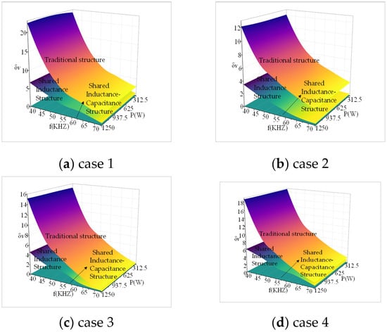
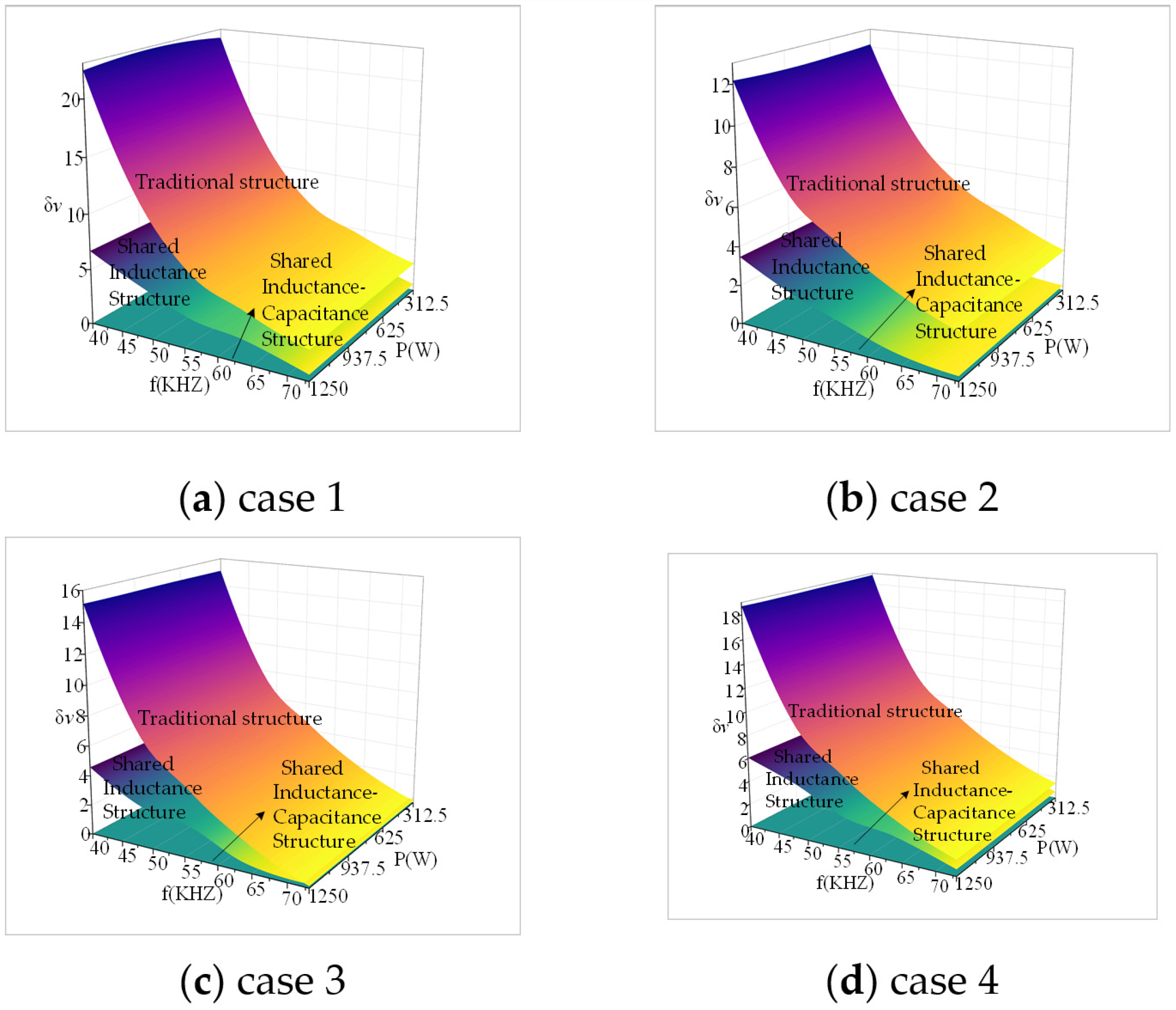
At this point, the relationship between U1(s) and U2(s) can still be expressed using k. Based on the analysis in Section 3.3, and combining Equations (10), (14) and (20), the voltage equalization error δv can be determined. The related simulations will be discussed in detail in Section 5.3.
4.2. Current-Sharing Analysis of the Proposed Structure
The equivalent circuit model of the proposed structure considering parasitic parameter mismatches is shown in Figure 14.
Figure 14.
Equivalent circuit model considering parasitic parameters.
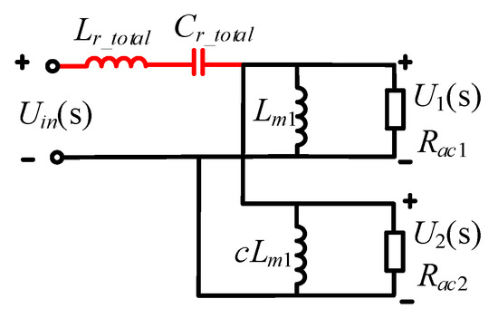
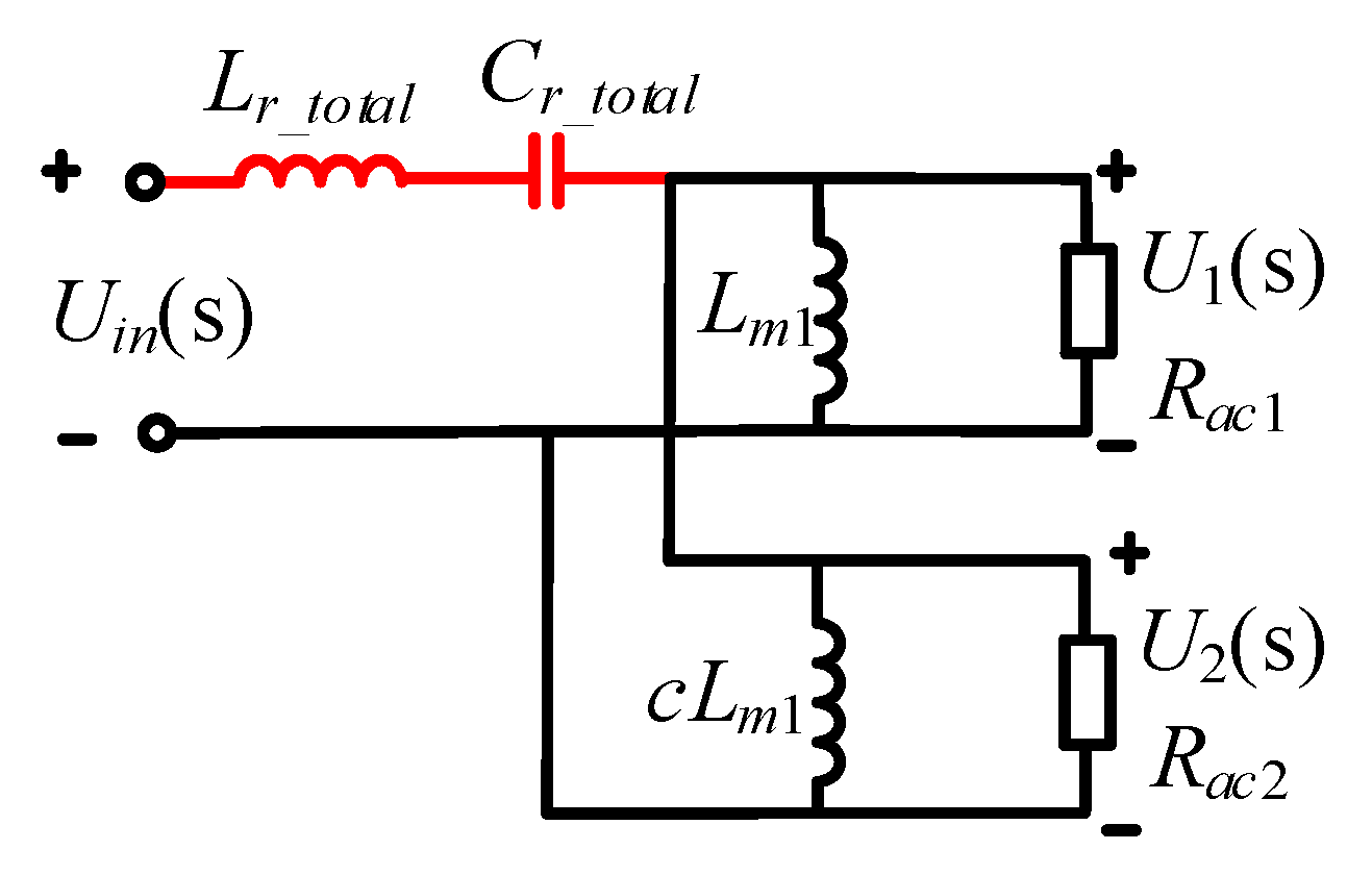
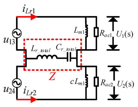
Lr_total and Cr_total are the total resonant inductance and total resonant capacitance, and their expression is still represented in Equation (12). R_total is the total on-resistance of the switches, and it is expressed in Equation (21).
where
The input voltage relationship can be expressed as:
Due to the parallel output, u13 = u24, the relationship between U1(s) and U2(s) can be expressed using k. By combining Equations (10) and (23), the values of iLr1 and iLr2 can be determined. Substituting them into Equation (18), the current-sharing error δi can be calculated. The related simulations will be discussed in detail in Section 5.3.
5. Simulation Validation
5.1. Simulation Results Without Considering Parasitic Parameter Mismatches
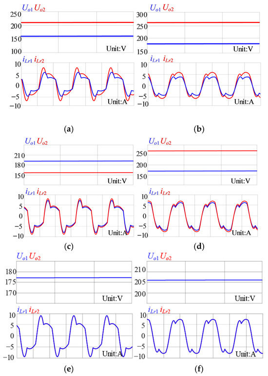
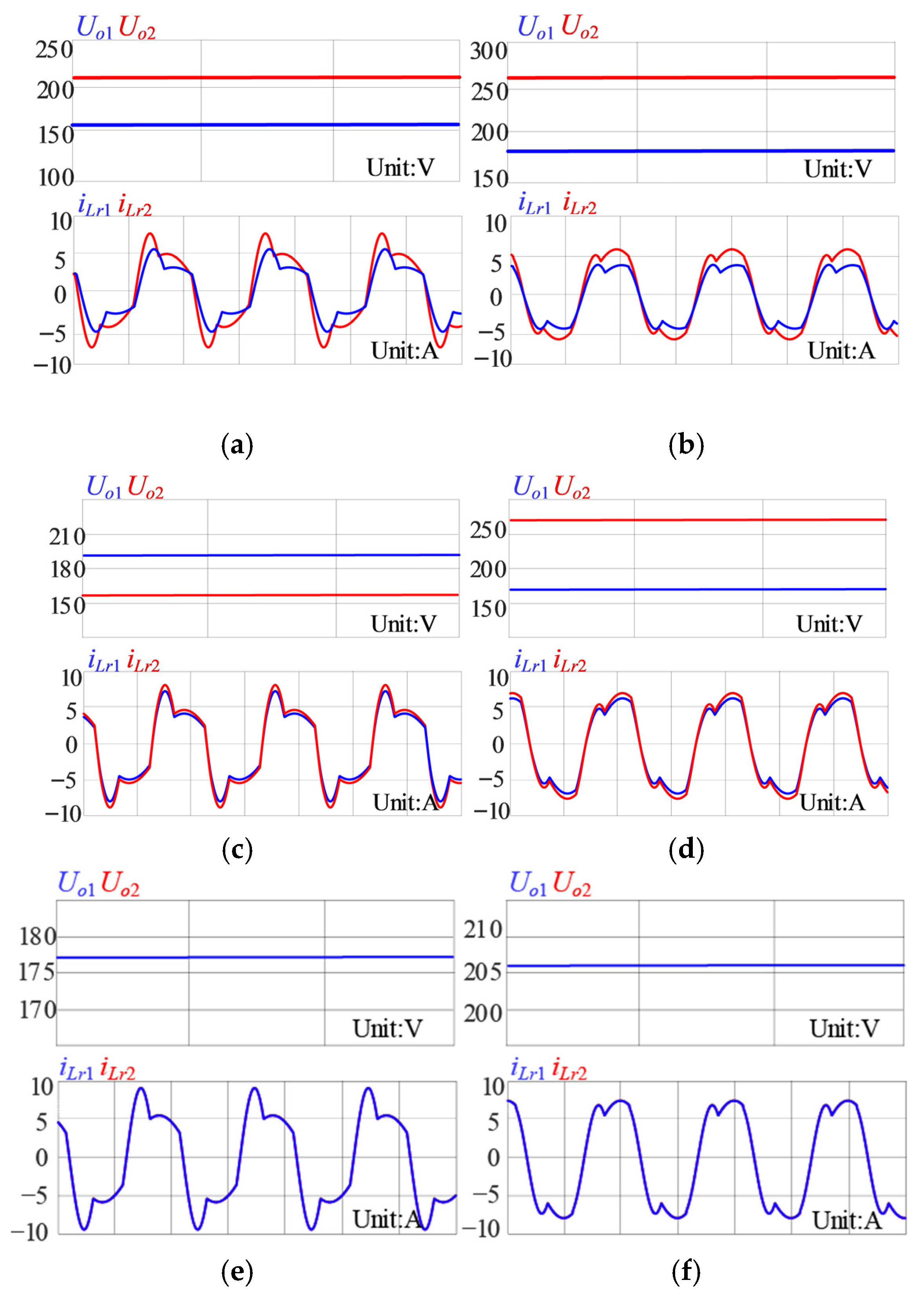
To verify the effectiveness of the proposed method, simulation validation was performed. The parameters of the two-phase LLC converter are shown in Table 2. According to theoretical analysis, the switching frequency was selected for the most adverse condition, 40 kHz. The maximum voltage equalization error occurs when the parameter errors are set to −10%. Therefore, the most unfavorable parameter mismatch combination was used: (a = 0.9, b = 0.9, c = 0.9). Figure 15 shows the PSIM simulation waveforms of the two-phase output voltage and resonant current for the three structures under full-load and operating conditions.
Figure 15.
Simulation waveforms of load voltage and resonant current for each structure. Traditional structure: (a) full load, (b) half load. Shared inductance structure: (c) full load, (d) half load. Proposed structure: (e) full load, (f) half load.
Under the above errors, whether the system is under full-load or half-load conditions, the traditional structure LLC converter exhibits significant voltage and current imbalances. Under half-load conditions, the output voltage and input current error between the phases reaches 21.12%. Even with the shared inductance structure, the output voltage error remains at 14.2%, and the resonant current error is 5.29%. However, as shown in Figure 15e,f, regardless of full-load or half-load conditions, the proposed shared inductance–capacitance structure achieves balanced two-phase output voltage and resonant currents.
Table 3 presents the load voltages and output voltage-sharing errors obtained from PSIM simulations and FHA calculations.
Table 3.
Simulation data and FHA data for each structure.
As shown in Table 3, the deviation calculated by the FHA is significantly larger than the simulation results. The reason for this is that the FHA method neglects the influence of higher-order harmonics, leading to a discrepancy between its calculations and the actual simulation results. Since FHA only considers the fundamental harmonic component, the calculated voltage gain is lower. Therefore, to achieve the same output voltage, the switching frequency predicted by FHA is always lower than the actual simulation frequency. In other words, the actual switching frequency is higher than the FHA-predicted value. Overall, the simulation results are more reliable than the FHA method in all cases.
5.2. Simulation Results of the Proposed Method in Multi-Module Systems
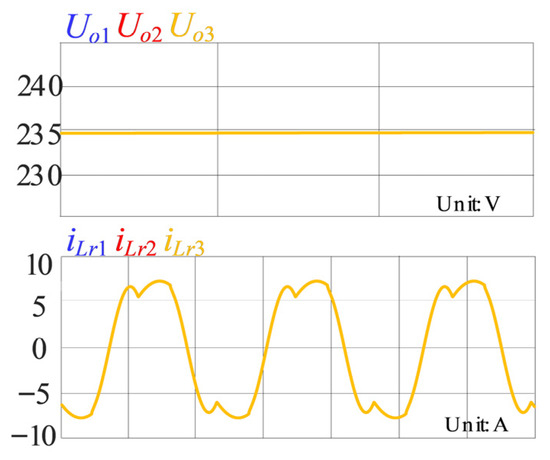
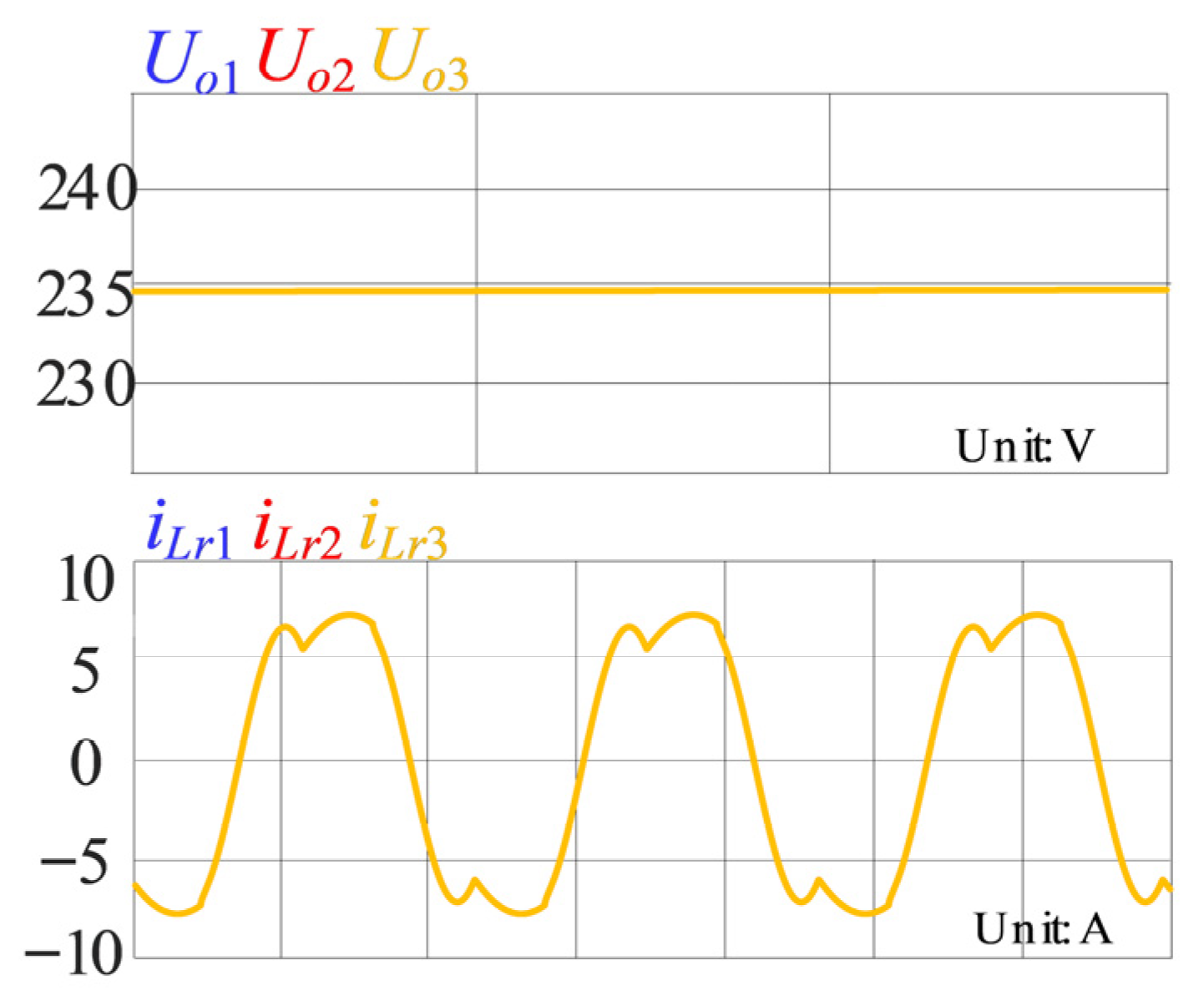
To verify the effectiveness of the proposed method in multi-module systems, a simulation was conducted using a three-module system as an example. The converter parameters are shown in Table 2. Based on the analysis above, the most adverse conditions were chosen: half-load operation with a switching frequency of 40 kHz and parameter mismatches using the two error combinations with the worst output voltage mismatch levels as defined in Section 3.5, specifically Case 1 (a = 0.9, b = 0.9, c = 0.9) and Case 4 (a = 1, b = 0.9, c = 0.9), ensuring distinct errors across the three modules. Figure 16 shows the PSIM simulation waveforms of the output voltage and resonant current for each module under these conditions.
Figure 16.
Simulation waveforms of load voltage and resonant current for the three-module system of the proposed structure.
As shown in Figure 16, the proposed structure effectively achieves voltage equalization and current sharing across phases in the N-phase system. This ensures that the voltage equalization and current-sharing characteristics of the output voltage and input current in the multi-phase system are not affected by resonant component parameter differences, significantly improving the system’s stability and reliability.
5.3. Simulation Results Considering Parasitic Parameter Mismatches
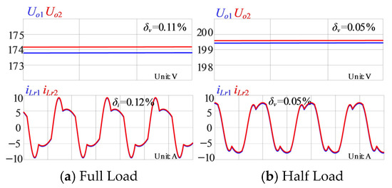
To verify the effectiveness of the proposed method under parasitic parameter mismatches, a simulation was conducted. The parameters of the two-phase LLC converter are shown in Table 4. Based on the theoretical analysis, the switching frequency was selected for the most adverse condition, 40 kHz, and the parameter errors were set to −10%, i.e., (a = 0.9, b = 0.9, c = 0.9, d = 0.9, e = 0.9). Figure 17 shows the PSIM simulation waveforms of the two-phase output voltage and resonant current for the proposed structure under full-load and half-load conditions with these errors.
Table 4.
Converter parameter indicators.
Figure 17.
Simulation waveforms of load voltage and resonant current for the proposed structure.
Under the maximum error of parasitic parameters, the voltage and current equalization errors at full load are only 0.11% and 0.12%. Therefore, the proposed shared inductance–capacitance structure can achieve balanced two-phase output voltage and resonant currents.
6. Experimental Verification
6.1. Steady-State Experimental Result Validation
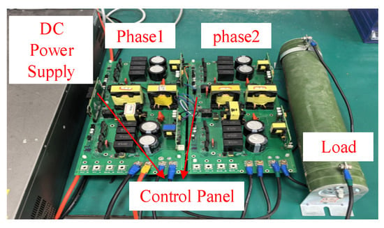
To verify the voltage and current equalization performance of the proposed structure, a 1.25 kW two-phase LLC resonant converter prototype was built, as shown in Figure 18. The two-module LLC resonant converter shared the same control board, and the consistent timing of the power devices was ensured by sending unified driving signals. The actual parameters of the experimental platform prototype are shown in Table 5.
Figure 18.
The proposed experimental platform for the common inductance capacitor LLC converter.
Table 5.
Experiment parameters.
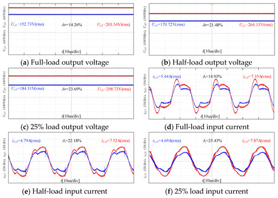
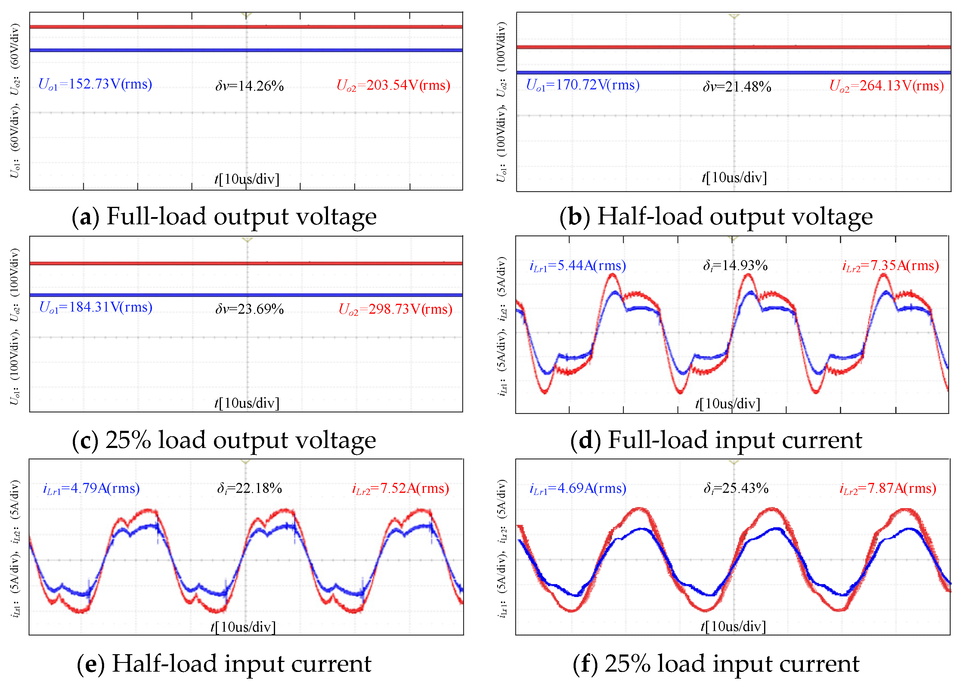
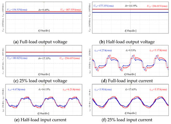
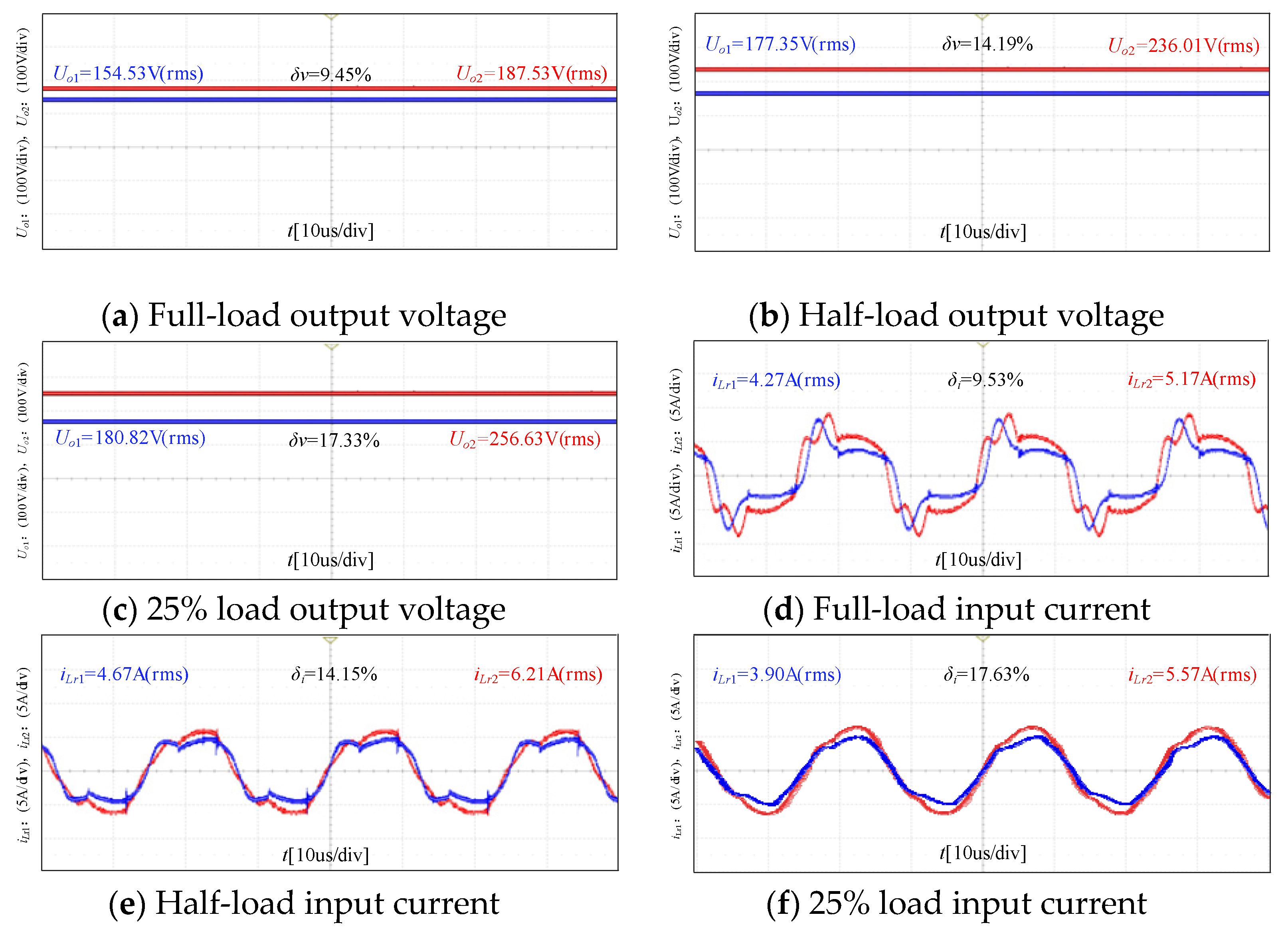
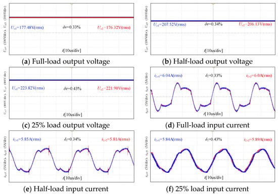
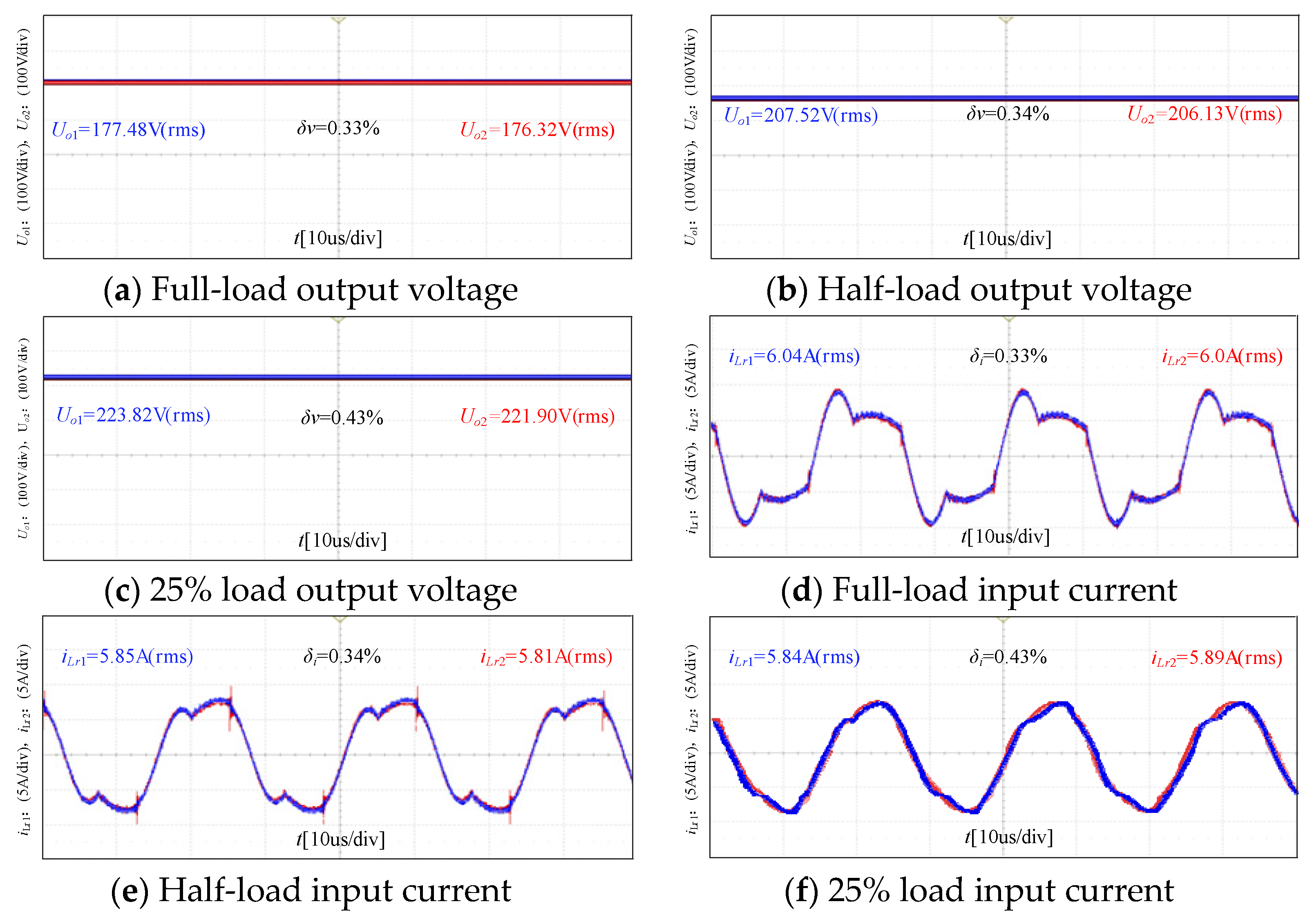
With an input voltage of 100 V, rated power of 1.25 kW, and switching frequency of 40 kHz, Figure 19a–c present the output voltage waveforms of the traditional structure under full-load, half-load, and 25% load conditions, respectively. Figure 19d–f show the corresponding input current waveforms. Figure 20a–c illustrate the output voltage waveforms of the interconnected shared-inductor structure under the same three load conditions, while Figure 20d–f display the associated input current waveforms. Likewise, Figure 21a–c plot the output voltage waveforms of the proposed shared-inductor–capacitor structure under full-load, half-load, and 25% load conditions, and Figure 21d–f show the corresponding input current waveforms.
Figure 19.
Experimental waveform of the traditional structure.
Figure 20.
Experimental waveform of the interconnection-line shared inductance structure.
Figure 21.
Experimental waveform of the interconnection-line shared. inductance and capacitance structure.
From the experimental waveforms, the traditional structure exhibits two-phase output voltage errors of 14.26%, 21.48%, and 23.69% at full-load, half-load, and 25% load conditions, accompanied by input current errors of 14.93%, 22.18%, and 25.43%. For the interconnected shared inductor structure, the corresponding voltage errors are 9.45%, 14.19%, and 17.33%, while the current errors are 9.53%, 14.15%, and 17.63% under the same loading conditions. Strikingly, the proposed shared inductance–capacitance structure achieves ultra-low errors: only 0.33%, 0.34%, and 0.43% for both output voltage and input current throughout the entire load range. These results validate that the proposed structure realizes superior voltage and current balancing over the full operating range of the converter.
It is important to highlight that the proposed shared inductance–capacitance structure mitigates the issue of resonant current imbalance by establishing a unified shared inductance–capacitance network. This approach significantly reduces the resonant tank stress induced by current imbalance and prevents the additional losses associated with resonant current misbalance.
6.2. Dynamic Experimental Results
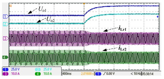
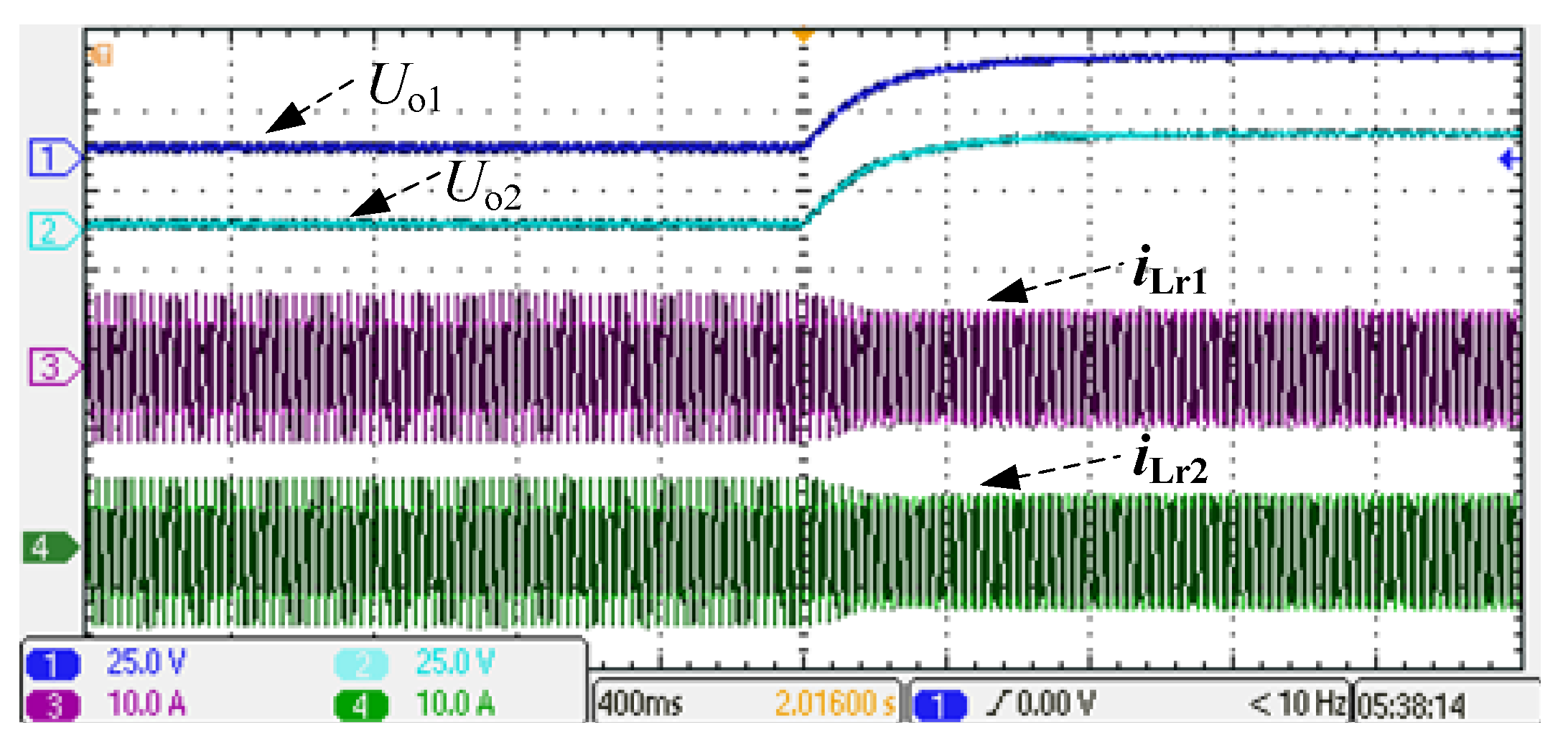
Figure 22 shows the experimental waveforms of the output voltage and resonant current for the two modules, corresponding to the full-load and half-load conditions of the proposed method.
Figure 22.
Output voltage and resonant current of the two modules during the transition from full load to half load.
As shown in Figure 22, during the transition from full load to half load, the system is able to maintain stable output voltages Uo1 and Uo2, which fully demonstrates the excellent voltage-balancing capability of the proposed scheme during load switching. Meanwhile, during the switching process, the resonant currents iLr1 and iLr2 of the two modules remain highly synchronized, and the current distribution between the modules stays balanced, further proving that the system can maintain outstanding current-sharing characteristics under different load conditions. The system quickly stabilizes to the new operating state, indicating that the proposed solution has excellent responsiveness and stability under dynamic load variations, showcasing its voltage and current equalization ability in dynamic processes.
6.3. Comparison with Existing Solutions
The method proposed in this paper includes a unified shared inductance–capacitance branch using interconnection lines to achieve voltage and current equalization. The significant advantage or distinction of this method lies in its avoidance of complex control strategies and its modular characteristics. The comparison with existing active/passive equalization solutions is shown in Table 6.
Table 6.
Comparative Analysis of Existing Equalization Solutions.
By comparison, the specific advantages of this solution are as follows:
- (1)
- The ease of implementation and reliability of this method are superior to active balancing methods. For instance, droop control requires four current sensors and a complex control strategy, resulting in poor dynamic performance.
- (2)
- Compared to other passive equalization methods, the proposed solution has lower complexity and features modularity, making it easier to scale to multi-phase systems as the system’s power capacity increases. This approach shortens the development cycle and reduces development costs.
7. Conclusions
To address the imbalances in output voltage and input current caused by parameter differences in the resonant tank components of input-parallel output-series LLC resonant converters, a new interconnection-line shared inductance–capacitance IPOS-type LLC resonant converter is proposed. This method achieves output voltage equalization and input current sharing between modules without the need for additional components or control strategies, significantly reducing system costs.
Furthermore, a new fundamental harmonic equivalent mathematical model is established for the proposed structure. Based on this model, the voltage and current equalization performance of the proposed converter is analyzed and compared with the voltage and current equalization characteristics of the traditional structure and interconnection-line shared inductance structure. Finally, the performance of a two-phase LLC resonant converter prototype is experimentally validated. The experimental results demonstrate that the proposed structure significantly reduces the output voltage and input current errors between the two phases under different resonant tank parameter variations. Additionally, this structure can be effectively extended to N-phase systems, providing an efficient voltage and current equalization solution for multi-module IPOS-type LLC resonant converters, with broad application prospects.
Future work will focus on in-depth investigations into the proposed shared inductance–capacitance structure, further evaluating its overall performance under non-ideal operating conditions. The planned tests and analysis include quantitatively assessing resonant tank voltage and current stress, system efficiency, and loss distribution tests. These endeavors will elucidate the impact of the proposed structure on voltage and current equalization accuracy, operational stability, and overall system performance.
Author Contributions
Methodology, A.L.; Software, A.L.; Validation, A.L.; Formal analysis, W.T.; Investigation, A.L.; Resources, J.L.; Writing—original draft, A.L.; Supervision, J.L. and W.T.; Project administration, J.L. and W.T. All authors have read and agreed to the published version of the manuscript.
Funding
This research received no external funding.
Data Availability Statement
The original contributions presented in this study are included in the article. Further inquiries can be directed to the corresponding author.
Conflicts of Interest
The authors declare no conflict of interest.
References
- Páez, J.D.; Frey, D.; Maneiro, J.; Bacha, S.; Dworakowski, P. Overview of DC–DC Converters Dedicated to HVdc Grids. IEEE Trans. Power Deliv. 2019, 34, 119–128. [Google Scholar] [CrossRef] [Scilit]
- Hu, P.; Yin, R.; He, Z.; Wang, C. A Modular Multiple DC Transformer Based DC Transmission System for PMSG Based Offshore Wind Farm Integration. IEEE Access 2020, 8, 15736–15746. [Google Scholar] [CrossRef] [Scilit]
- Dinh, M.-C.; Le, T.-T.; Park, M. A Stacked Symmetrical Non-Isolated High Step-Up Voltage Gain Converter with High Efficiency and Low Voltage Stress on Components. Energies 2024, 17, 1668. [Google Scholar] [CrossRef] [Scilit]
- Chen, J.; Wang, C.; Li, J. An Input-Parallel-Output-Series Switched-Capacitor Three-level Boost Converter with a Three-Loop Control Strategy. Energies 2018, 11, 2631. [Google Scholar] [CrossRef] [Scilit]
- Hu, X.; Gong, C. A High Gain Input-Parallel Output-Series DC/DC Converter with Dual Coupled Inductors. IEEE Trans. Power Electron. 2015, 30, 1306–1317. [Google Scholar] [CrossRef] [Scilit]
- Wang, P.; Zhou, L.; Zhang, Y.; Li, J.; Sumner, M. Input-Parallel Output-Series DC-DC Boost Converter with a Wide Input Voltage Range, For Fuel Cell Vehicles. IEEE Trans. Veh. Technol. 2017, 66, 7771–7781. [Google Scholar] [CrossRef] [Scilit]
- Jang, S.-R.; Seo, J.-H.; Ryoo, H.-J. Development of 50-kV 100-kW Three-Phase Resonant Converter for 95-GHz Gyrotron. IEEE Trans. Ind. Electron. 2016, 63, 6674–6683. [Google Scholar] [CrossRef] [Scilit]
- Wang, H.; Chen, Y.; Liu, Y.-F.; Afsharian, J.; Yang, Z. A Passive Current Sharing Method with Common Inductor Multiphase LLC Resonant Converter. IEEE Trans. Power Electron. 2017, 32, 6994–7010. [Google Scholar] [CrossRef] [Scilit]
- Dong, H.; Xie, X. Review of Current-Sharing Schemes for Multiphase LLC Resonant Converter. IEEE Trans. Power Electron. 2025, 40, 1322–1345. [Google Scholar] [CrossRef] [Scilit]
- Dong, X.; Wu, H.; Lu, Y.; Hu, H.; Sun, K. Distributed autonomous voltage balancing control for a modular IPOS DC grid-connected renewable power system. In Proceedings of the 2018 IEEE Applied Power Electronics Conference and Exposition (APEC), San Antonio, TX, USA, 19 April 2018; pp. 1136–1140. [Google Scholar] [CrossRef] [Scilit]
- Liu, H.; Fang, T.; Lin, Z.; Wang, P.; Huang, X.; Li, Y. Droop Control Strategy Without Interconnection Lines for Input-Parallel Output-Series Grid-Connected Inverter System. IEEE Trans. Ind. Electron. 2024, 71, 15224–15228. [Google Scholar] [CrossRef] [Scilit]
- Yu, Z.; Zhao, Y. Study of a Dual-Loop Digital Control System for High-Power Input-Parallel Output-Series Phase-Shifted Full-Bridge Converters Based on Pole Configuration. Int. J. Circuit Theory Appl. 2025, 53, 5288–5304. [Google Scholar] [CrossRef] [Scilit]
- Zhang, C.; Zhou, Y.; Zhao, Y.; Ding, X.; Yu, D. Self-Adapting Voltage Balancing Method for IPOS Dual Active Bridge Converter with CTPS Control. In Proceedings of the 2023 IEEE International Conference on Applied Superconductivity and Electromagnetic Devices (ASEMD), Tianjin, China, 25–27 November 2023; pp. 1–3. [Google Scholar] [CrossRef] [Scilit]
- Huang, X.; Wang, H.; Guo, L.; Ju, C.; Liu, R.; Meng, S.; Wang, Y.; Xu, H. Large-scale photovoltaic generation system connected to HVDC grid with centralized high voltage and high power DC/DC converter. In Proceedings of the 2017 20th International Conference on Electrical Machines and Systems (ICEMS), Sydney, NSW, Australia, 5 October 2017; pp. 1–6. [Google Scholar] [CrossRef] [Scilit]
- Li, Y.; Shao, S.; Chen, H.; Zhang, J.; Sheng, K. High-gain high-efficiency IPOS LLC converter with coupled transformer and current sharing capability. CPSS Trans. Power Electron. Appl. 2020, 5, 63–73. [Google Scholar] [CrossRef] [Scilit]
- Kui, L. Research on Topology and Control of Wide Gain and High Efficiency Series-Parallel LLC Resonant Converter. Doctoral Dissertation, Hunan University, Changsha, China, 2021. [Google Scholar] [CrossRef]
- Sun, Z.; Wang, Q.; Wu, Q.; Xiao, L.; Li, J.; Liu, Z.; Zhu, J. A Unified Common Inductor and Common Capacitor Current Sharing Method for Multiphase LLC Converter. IEEE Trans. Power Electron. 2022, 37, 12182–12196. [Google Scholar] [CrossRef] [Scilit]

Disclaimer/Publisher’s Note: The statements, opinions and data contained in all publications are solely those of the individual author(s) and contributor(s) and not of MDPI and/or the editor(s). MDPI and/or the editor(s) disclaim responsibility for any injury to people or property resulting from any ideas, methods, instructions or products referred to in the content. |
© 2026 by the authors. Licensee MDPI, Basel, Switzerland. This article is an open access article distributed under the terms and conditions of the Creative Commons Attribution (CC BY) license.