


Abstract
High-altitude and high-speed aircraft generate substantial aerodynamic heat during flight, creating a harsh thermal environment in the engine compartment that risks overheating and burnout of control components and fuel and lubricating oil accessories. Consequently, the thermal protection system (TPS) design for engine accessories has become one of the key technologies in hypersonic vehicle design. Based on certain TBCC, this paper uses a modular active-passive integrated TPS design and employs the quality management experimental design tool to optimize the design and decouple the method proposed on the modular design boundaries. This paper is the first to combine modular design with design of experiments (DOE) tools and apply them to the TPS of high-altitude and high-speed combined power accessories. The design scheme is optimized by identifying the main influencing factors. The optimized TPS scheme decreases the performance loss by 10% and increases cooling efficiency by 22–26%. The proposed engineering method shortens the development cycle significantly and improves efficiency by 78%. The modular design method for accessory TPS provided in this paper has good engineering applicability and can be widely used in the early stages of thermal protection scheme design, scheme optimization, scheme selection, and overall thermal management of hypersonic combined power systems.
1. Research Background
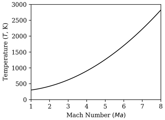
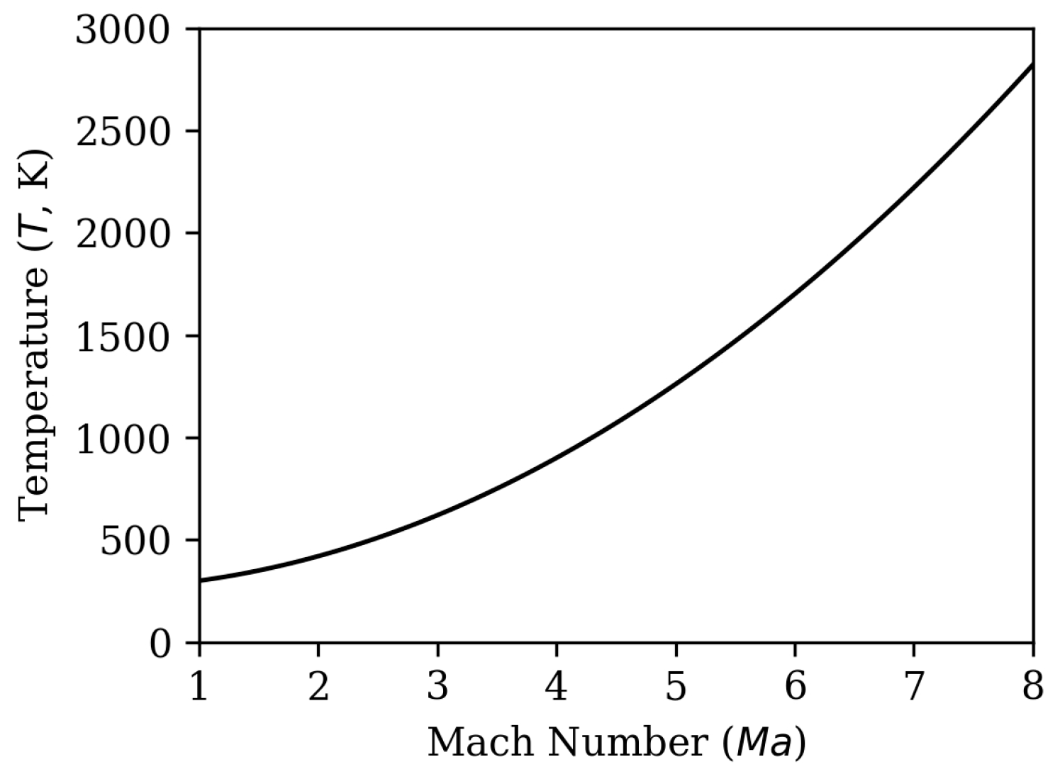
Hypersonic vehicles experience severe aerodynamic heating when they work at high Mach numbers. As shown in Figure 1 [1], the total temperature of incoming air is positively correlated with the flight Mach number, and it increases exponentially with the increase in the aircraft’s operating Mach number. This makes the cooling capacity of air as a cold source increasingly limited [2,3].
Figure 1.
The temperature change to engine air intake Mach number.
To address the thermal environment characteristics, thermal protection and internal cabin thermal management requirements of hypersonic vehicles [4,5], a series of thermal protection measures have been proposed in academic and engineering fields. Domestic scholars have proposed an integrated internal and external cabin thermal protection design: engine waste heat isolation is adopted in high-temperature regions, and active/passive thermal protection measures in low-heat-flux regions [6]. A scholar [7] suggests using a thermal storage-type hypersonic vehicle cabin for thermal protection. Phase change energy storage materials are used to adapt to dynamic heat changes throughout the full flight profile (including on the ground at the low temperatures) and maximize gradient thermal energy utilization. In addition, the integrated design of traditional passive thermal protection materials and structures has become a research focus in recent years. For example, the tile-type thermal protection system integrated design mentioned in Reference [8] is characterized by low cost and reliability.
For the above thermal protection measures, scholars have conducted extensive research on the methods for formulating relevant engineering schemes. Domestic and foreign scholars have conducted extensive research on the TPS design for aircraft. Foreign scholars have used engineering methods to calculate the heat flux of surface feature points on aircraft, combined with the one-dimensional temperature of thermal protection materials at these feature points, to achieve rapid TPS design and develop corresponding software platforms [9]. There are also corresponding thermal protection calculation methods and thermal response prediction methods applicable to multiple types of TPS in China [10]. Using automated selection of thermal protection methods, a complete and rapid design of general hypersonic aircraft thermal protection systems is proposed.
Scholars [11] have adopted various strategies for the cooling of engine accessories and experimentally evaluated their cooling effectiveness. However, they did not propose the requirements for design boundaries or the method to obtain the optimal scheme under multi-boundary constraints. In the engineering application of thermal protection technology, multi-boundary coupling is commonly encountered. For example, the heat sink of active thermal protection is limited by flight weight and performance loss, which makes it unable to satisfy the requirements over the full flight profile. Similarly, passive thermal protection structures cannot be implemented due to space and weight constraints. Therefore, the optimization of thermal protection design schemes is the key to high-efficiency design.
From the perspective of power cycles, hypersonic vehicles can be classified into TBCC, RBCC, scramjet and rocket propulsion. TBCC, which includes a turbine engine, enables long-duration and reusable operation, thus representing the mainstream scheme for hypersonic aircraft at the current stage.
Furthermore, the reliability and controllability of the turbine engine rely on numerous control accessories and fuel oil accessories. Under multi-boundary constraints such as space, weight, and heat sink, flexible design approaches and optimization in the thermal protection design of accessories are critical to the development of hypersonic aircraft.
In this paper, the thermal protection of accessories is modularized, and the DOE tool is used to identify the key influencing factors to optimize and decouple, thereby forming an efficient thermal protection design scheme.
2. Thermal Protection Design Requirements
2.1. Application Scenario for TPS in TBBC
The TBCC engines studied in this article are a combination of turbine and ramjet engines, with a flight range under M3-4 [12].
The thermal protection scheme of the turbine needs to meet the working requirements of the combined engine when the aircraft fly at a Mach number 0–4 long-term operation, or at no-power return period and the entire turbine restarting period. Taking NASA’s TBCC as an example: turbine mode from Mach 0 to 3, transition point at Mach 3, scram-jet mode from Mach 3 to 8, horizontal takeoff and landing. To simplify the analysis, it can be considered that the turbine thermal protection requirements need to be met in the following four stages: A, B, C, and D [13].
- Engine start-up to completion of modal transition.At this point, the turbine module needs to complete the processes of starting, accelerating, mode rotation, and stopping oil. When transitioning between modes, the airflow rate of the ramjet engine in the parallel TBCC propulsion system increases to a certain value, and the ramjet engine begins to ignite. At the same time, the amount of fuel for the afterburner combustion is reduced, and the outlet temperature of the afterburner combustion chamber is gradually lowered [14]. The TBCC combined power is converted into a separate output of the ramjet engine.
- Modal conversion completed to high-speed channel shutdown.At this point, the turbine module completes the processes of mode rotation, fuel shutdown, windmill, and shutdown, and the aircraft climbs up to the end of the mode transition point along the flight trajectory. For stamping mode operation, the total temperature of the incoming air is relatively high at this time. At this moment, the turbine engine is subjected to high-temperature airflow convection and high-temperature ramjet engine radiation in the engine compartment.
- Shutdown of high-speed channel to restart of turbine.The turbine module remains in a shutdown state, the high-speed channel stops oil, and the interior is filled with high-temperature incoming air [15].
- Turbine engine running until shutdown.
2.2. Maximum Thermal Design Point of Combined Power
Based on the characteristics of temperature changes in the engine compartment, this article reposes the maximum state point for thermal design:
Maximum thermal design point 1: the starting point for the transformation of combined dynamic modes. At the beginning of modal transition, the turbine engine is at the transient point where acceleration ends, and the turbine engine is in a high state. At this time, the attachments on the surface of the turbine generate the maximum heat, bear the high heat load of the main engine, and the heat load on the casing wall is uneven. Moreover, the aircraft is flying at high altitude and high speed, and the ambient airflow in the engine compartment is high. Therefore, the thermal environment of the attachment at this state point is relatively harsh, and it is one of the maximum assessment points for heat load. In Figure 1, it can be seen that the incoming temperature of the engine is around 700 K, and the mainstream temperature reaches 2000 K [16].
Maximum thermal design point 2: the end point of combined dynamic mode conversion. At the end of modal transformation, the low-speed channel is closed, the high-speed channel is opened separately, and the stamping engine works separately. At this time, the aircraft is flying at high altitude and speed, and the ambient airflow in the engine compartment is relatively high. Additionally, during the operation of the ramjet engine, the wall temperature is relatively high, and the turbine accessories receive thermal radiation from the ramjet engine and other high-temperature wall surfaces inside the engine compartment. In Figure 1, it can be seen that the incoming temperature of the engine is around 1000 K, and the mainstream temperature reaches 2400 K.
2.3. Main Requirements for Thermal Protection in Attachments
- When the accessory TPS is working, it does not affect the safety and performance of the combined power engine.
- After the cooling system of the insulated cabin is put into operation, it will experience a transient and steady state within the flight envelope, and the working environment of the accessories inside the cabin will not exceed the safe working environment temperature of the accessories [17]. The details are shown in Table 1.Table 1. Safe temperature range for accessories.
- Long-term safe operating temperatures of the materials are above 500 °C.
- It does not affect the assembly and positioning of the engine and other components in the engine compartment, and is easy to install and remove.
3. Modular Thermal Protection Design
To address the flight requirements, this study introduces a modular design methodology. This approach is particularly valuable during early-stage design phases through parallel implementation of multiple solutions and iterative optimization processes. The modularized design framework not only reduces the complexity of thermal protection systems for accessories but also enhances system maintainability while improving the specificity of cooling requirements. The modularity of this paper mainly contains two types of modules, and the second type being centralized + decentralized cooling is core.
3.1. Active/Passive Thermal Protection Modular Design
- Passive thermal protection scheme
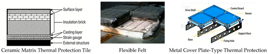
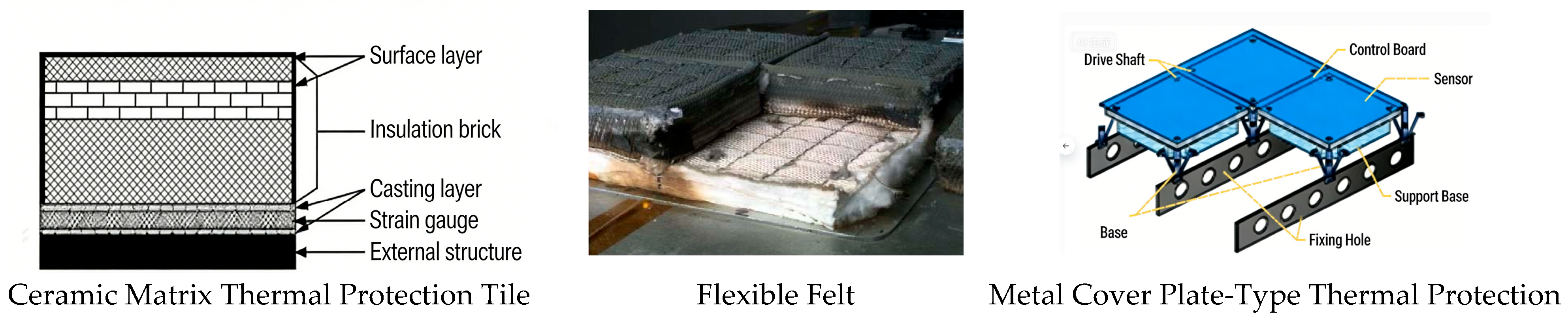
Mainly relying on heat-resistant structures and materials themselves to absorb or radiate heat, without the need for working fluids [18]. It is simple, reliable, and widely used. It is able to maintain the aerodynamic shape unchanged. For example, its typical representative insulation structure is that the insulation layer prevents heat from transferring to the inner layer structure, and a small portion of the heat transmitted to the inner layer is stored in the structure through a heat sink [19]. Several typical passive thermal protection structures are shown in Figure 2.
Figure 2.
Passive thermal protection.
- 2.
- Active thermal protection system
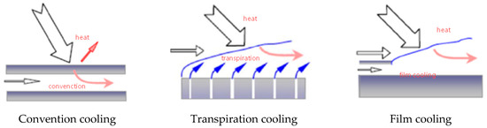
Active thermal protection mainly relies on cooling the working fluid to take away the vast majority of heat flow and reflect a small portion of heat [20]. Generally divided into sweating cooling, film cooling, and convective cooling [21], as shown in Figure 3.
Figure 3.
Active Cooling.
- 3.
- Semi-passive thermal protection
Semi-passive thermal protection is between active and passive thermal protection schemes, where most of the heat is carried away by workflow or airflow. It mainly adopts two structural forms: heat pipe structure and ablation structure [22].
Generally, the thermal load ratio between active and passive thermal protection is determined based on the cooling environment objectives of the accessory, spatial positioning of the accessory, and active cooling capacity, followed by detailed parameter design under modular configuration [23]. The coolant and passive materials jointly bear the thermal load. Determining the proportion of heat load each component should handle, along with selecting appropriate types and thicknesses for passive materials, constitutes the critical aspects of composite cooling system design. The design process involves: establishing optimal passive layer materials for thermal protection schemes by analyzing thermal load allocation coefficients, passive material temperature limits, thermal conductivity relationships, and thickness requirements, thereby comprehensively defining the preliminary thermal protection framework. The specific calculation process is as follows:
Under the active-passive composite thermal protection scheme, the heat flux under the same flight condition is defined as the thermal load ratio coefficient, which indicates the ratio of the heat flux density after active-passive composite to that under the active thermal protection (Equation (1)).
Convection between high-temperature gas and passive layer:
Passive layer wall heat transfer:
Active wall heat conduction:
where
- —High temperature side heat transfer coefficient (W/(m2·K)),
- —High temperature hot side temperature (K),
- —Convective heat flux density of high temperature gas and passive layer (K),
- , —Thermal conductivity of materials (W/(m·K)).
According to Equations (1)–(4), the different heat flows and different passive layers are obtained with different thermal conductivity and thickness.
3.2. Module Integration
Under the premise of completeness and simplicity, the engine thermal protection module of TBCC is divided as follows:
The engine accessories are centrally arranged and cooled using an insulated compartment. This TPS actively channels cold air to dissipate heat generated by high-temperature airflow convection in the engine cabin. Priority is given to installing components like the fan cowling within the compartment, with their layout optimized to meet temperature gradient requirements. The structural design integrates both heat transfer efficiency and structural integrity, ensuring rational and cost-effective utilization of cooling heat sinks.
For accessories that are temperature-specific, location-specific, frequently maintained, and require replacement, distributed cooling is used. For example, engine pressure/temperature sensors.
The heat shield module effectively blocks radiation from high-temperature components in the engine compartment, such as those from a stamped engine casing. This module can be integrated into either centralized or decentralized cooling systems, and may also be used independently. When installed on the opposite side of a high-temperature stamped engine casing, the standalone heat shield module can eliminate.
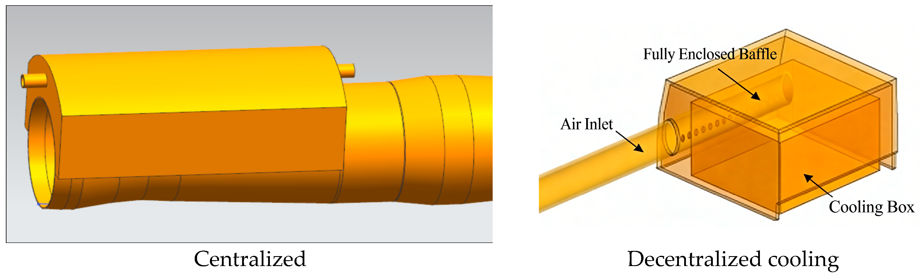
The enclosed cabin and decentralized cooling conditions in the accessory are shown in Table 2.
Table 2.
Overall layout of insulation and sealing of accessories.
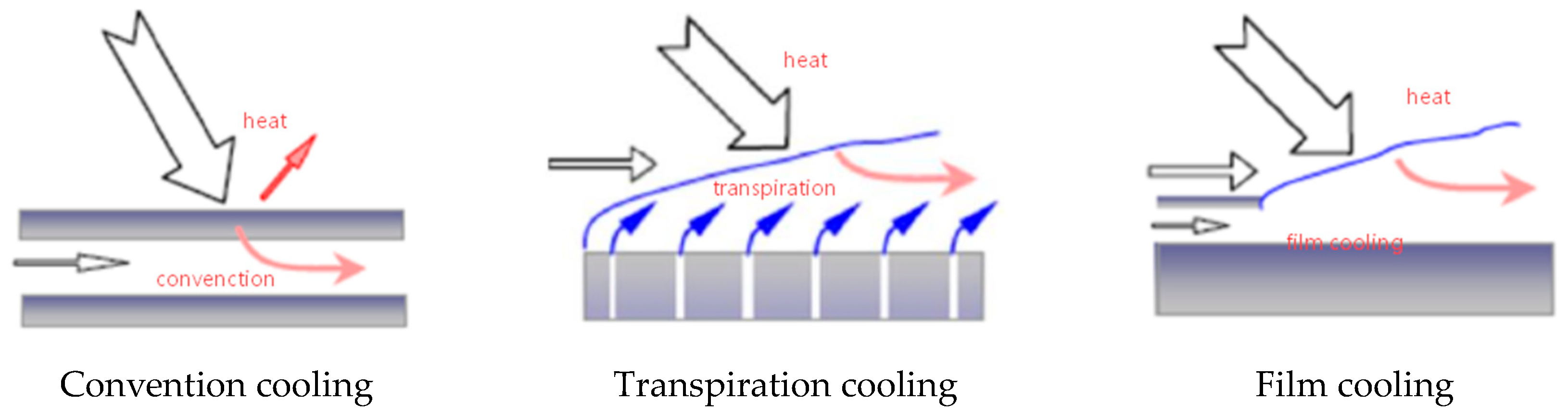
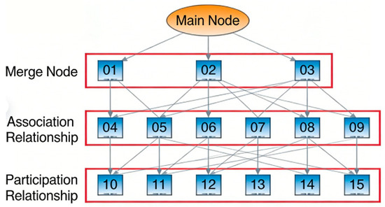
Develop a cooling flow path layout system diagram. Utilizing continuity equations, momentum equations, and energy equations as control systems, the networked flow paths are uniformly solved to obtain geometric features of primary and auxiliary pipelines. The integrated cooling system air system flow diagram is shown in Figure 4. Cooling endpoint design: thermal shield designs incorporating cooling heat sinks, including fully enclosed, semi-enclosed, and exhaust configurations. Based on actual installation positions of aircraft and engine accessories, the overall layout of accessory insulation compartments is shown in the diagram. Adopting a cascade cooling strategy for efficient cold source utilization, multiple zones of accessory insulation compartments undergo sequential cooling through circulating cold air. A typical schematic of the cooling structure is illustrated in Figure 5.
Figure 4.
Integrated cooling system air system flow diagram.
Figure 5.
A typical schematic of the cooling structure.
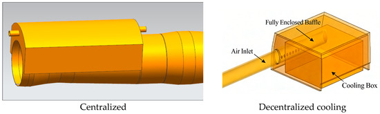
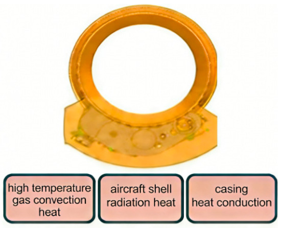
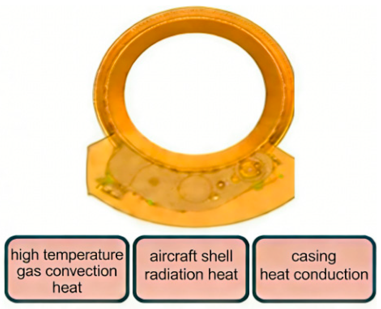
Figure 6 concerns heat in centralized and decentralized cooling modules.
Figure 6.
Heat transfer model.
Taking the insulated compartment as the research object, the thermophysical model of the sealed compartment is established, considering the cold and hot boundaries of the sealed compartment, and the cooling analysis method of the distributed unit is similar. There are four main heat sources in the compartment:
- Conduction of the engine block
- Convection heat transfer in the engine compartment
- Radiation heat transfer in the engine compartment
- Release of heat from accessories
The thermal physical modeling of the accessory insulation and sealing is completed according to the basic theoretical formula of heat transfer.
The control equation for the air conditioner is calculated as follows:
The calculation formula for air temperature increase in the sealed cabin is as follows:
For the cabin component control body:
where
- —The air conditioner takes away the heat (W),
- —Convective heat transfer on the insulation surface (W),
- —Convective heat on the skin surface (W),
- —Component convective heat (W),
- G—Cooling airflow (kg/s),
- C—Heat capacity of cooling air (K),
- Tout, Tin—Air inlet and outlet temperature (K),
- —The component itself generates heat (W),
- —Radiation received from components (W).
According to the above formula, the outer wall temperature of the sealed cabin is used as the iteration parameter to iteratively obtain aerodynamic parameters such as cooling airflow, pressure, and temperature under different state points. According to the flight requirements in Section 3.1, the active and passive heat insulation distribution is carried out.
3.3. Centralized + Decentralized Cooling Module Design
The following design boundaries for the thermal protection of engine accessories shall be considered: (1) ramjet engine casing walls with high-temperature radiation capacity; (2) engine surfaces experiencing extreme temperature fluctuations; (3) accessories with varying thermal resistance capabilities; (4) extreme flow field inhomogeneity under low-flow conditions in high-altitude negative pressure chambers; (5) cooling accessories positioned at different engine surface locations according to their functions; (6) flexible disassembly and replacement of cooling accessories.
The details of the design:
- Central cooling module
According to the actual installation position of the aircraft and engine accessories, the overall layout of the accessory insulation sealing chamber is shown in the figure. The idea of cascade high efficiency utilization of the cold source is adopted, and several zones of the accessory insulation sealing chamber are connected for cooling with cold air.
- 2.
- Decentralized cooling modules
A typical distributed cooling system consists of three parts: the main pipeline, the distributed cooling parallel pipeline, and the accessory cooling cover.
4. Optimization Design with DOE
In modular design, the active and passive thermal protection parameters of each module are influenced by a continuous thermal environment range, with multiple design options available for selection. Furthermore, various coupling methods between modules exist. The inherent uncertainties in these design factors necessitate optimizing the cooling system’s performance across multiple boundary conditions.
DOE serves as a crucial optimization tool for quality management [24]. This method focuses on designing experiments to achieve optimal results, deriving the best factor combinations through analysis of experimental data. It establishes mathematical relationships between influencing factors (Xn) and target response factors (Yn), obtaining systematic parameter and design optimization [25].
Common types of DOE include full factorial design, fractional factorial design, response surface methodology, Taguchi design, and Plackett–Burman design [26,27]. For efficient identification of the main influencing factors in engineering applications, the fractional factorial design was adopted in this study. Additionally, Minitab 15 software was employed for DOE.
The optimization process of the modular thermal protection scheme is as follows:
4.1. Sample Design
Make an experimental sample.
In this case, according to the aircraft flight conditions and accessory loads, the end point of mode transition—maximum thermal design point 2—is selected. Thus, the main thermal boundaries have been determined, such as: Mach 3.0, 20 km altitude, atmospheric pressure 5500 kPa, static temperature 216 K, and total temperature 600 K.
Selection criteria for influencing factors for DOE:
Physical relevance to the response variables; significant sensitivity to output performance; controllable and quantifiable in simulation; mutual independence and low correlation; reasonable range under engineering constraints.
Selection criteria for responses for DOE:
It should have a clear physical meaning, be highly relevant to the research objectives, quantifiable and obtainable from simulation, sensitive to changes in input factors, of practical engineering significance, and stable and reproducible.
The factors and responses considered in the study of cooling are shown in Table 3.
Table 3.
Factors and responses considered in the study of cooling.
Due to the influence of many factors, a fractional factorial experiment was used for the test, and 14 samples were obtained. The test was carried out 64 times by comparing a full factorial experiment, which greatly saved the cost and cycle of the experiment. The efficiency was improved by 78%.
Using the basic principle of heat transfer design in Section 2.1, one-dimensional and three-dimensional simulation calculations are carried out using each set of sample parameters to obtain the response Y1–Y4.
Experiment schemes under the influence of X1–X6 are shown in Table 4.
Table 4.
Affecting factors.
An example with CFD simulation results based on the ninth set is shown in Table 4.
In the CFD simulation modeling, referring to the influencing factors from the experimental design and in combination with thermophysical models, a complete and high-fidelity thermal-fluid coupling model was established. Grid independence verification shows that when the number of cells for each decentralized cooling structural unit exceeds 3 million, the variation amplitudes of key indicators Y1–Y4 are less than 2%, which meets the engineering accuracy requirements.
It should be noted that the cool air heat sink is 12,000 W. In this study, this corresponds to a temperature of 323 K, an average inlet velocity of 180 m/s, and an inlet-to-outlet pressure ratio of 1.6.
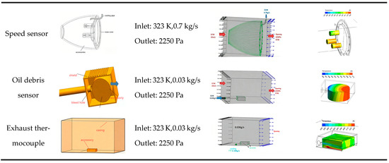
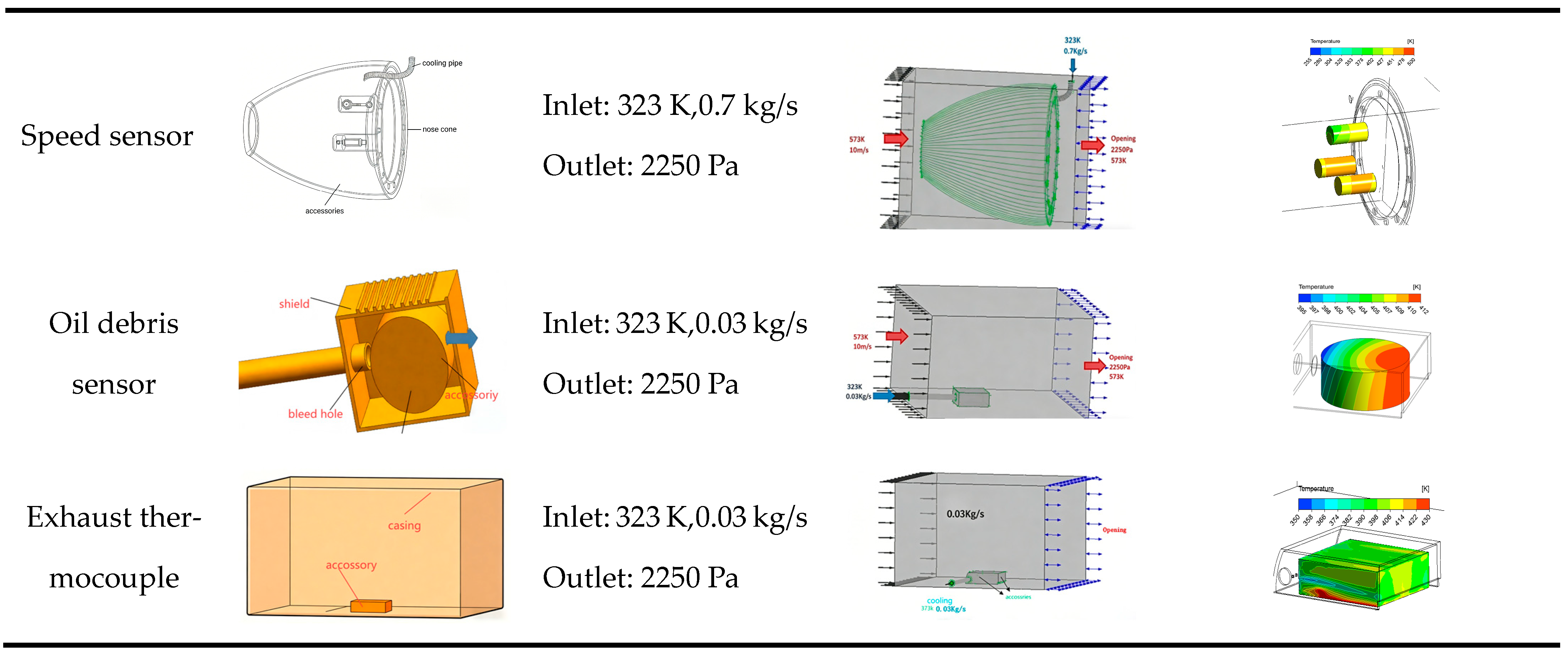
Figure 7 shows CFD flow and heat transfer simulation results of the accessories.
Figure 7.
Temperature results.
The speed sensor operates within a temperature range of −55 °C to 215 °C (218 to 488 K). During maximum thermal design point 2, the system can meet cooling requirements by introducing 0.7 kg/s of 323 K cold air, maintaining accessory temperatures at 210 °C. The temperature difference from the surrounding ambient temperature environment (260 °C) is 50 °C.
The oil debris sensor operates within a temperature range below 150 °C. During maximum thermal design point 2, the system provides 0.03 kg/s of 323 K cooling airflow to meet cabin insulation and sealing requirements, maintaining accessory temperatures below 139 °C while ensuring the Shuwo Signaler operates at no higher than 150 °C. The temperature difference from the surrounding ambient temperature environment (160 °C) is 10 °C.
The exhaust thermocouple operates within a temperature range not exceeding 200 °C. During maximum thermal design point 2, the 0.03 kg/s cooling airflow at 323 K maintains the accessory’s core temperature below 200 °C, effectively meeting its cooling requirements. The temperature difference from the surrounding ambient temperature environment (233 °C) is 33 °C.
The average temperature of the three distributed cooling points is 31 K. Using the same simulation analysis method for concentrated cooling, the resulting temperature is 37 K.
The mass increase ratio is defined as the ratio of the cooling system weight to the total weight of the engines’ combined power system. For the performance loss calculation, an empirical method is adopted, where the performance loss is determined according to the ratio of the extracted gas flow rate to the engine inlet flow rate under the corresponding operating condition.
The DOE experimental results together with the factor table for X are illustrated in Table 4.
4.2. Critical Factor Selection
Hypothesis testing is essential to statistically verify whether factors have significant effects and to ensure the reliability of regression models for engineering analysis and optimization [28].
This section presents the statistical test and analysis of the experimental data using a 6-factor fractional factorial design with 14 runs (including six center points) in Minitab. Four responses were evaluated by ANOVA, significance analysis, goodness-of-fit and lack-of-fit test.
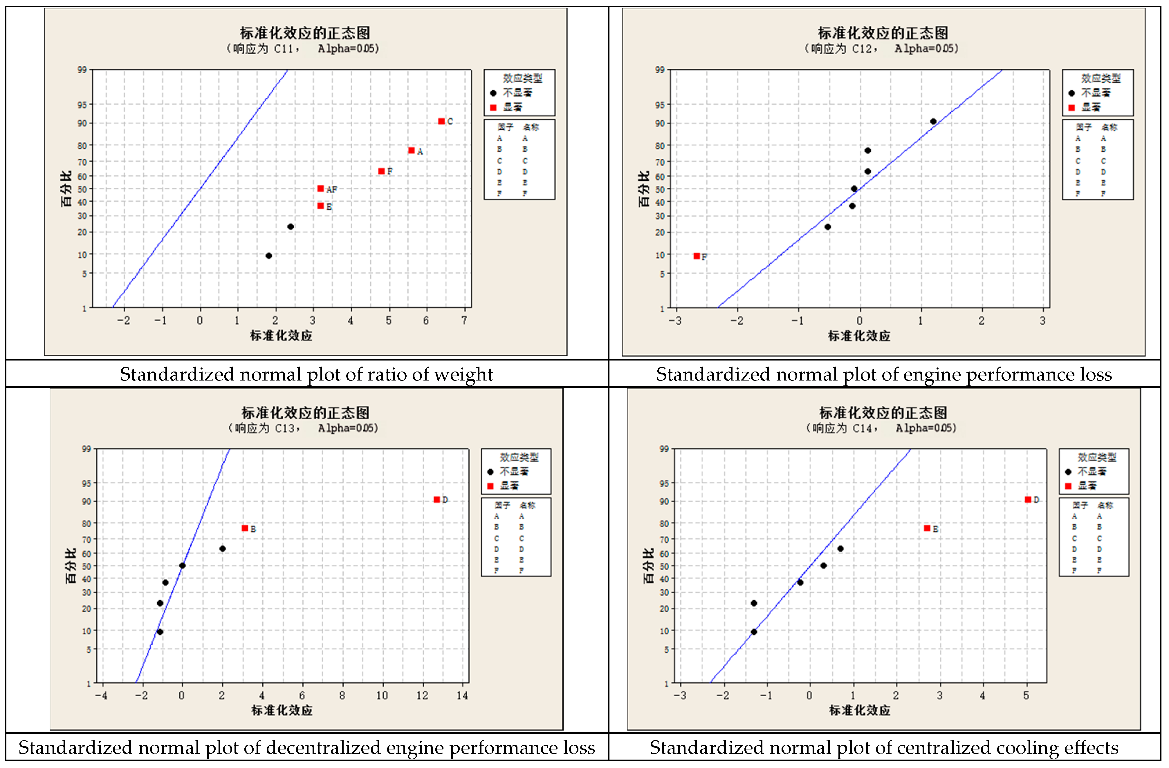
The results show that the regression models for engine performance loss and cooling effects are statistically significant (p < 0.05), with adjusted R-squared values of 90.44%, 92.99%, and 68.76%, respectively, and no significant lack-of-fit, indicating the models are reliable and suitable for effect analysis and optimization. The model for ratio of weight is not significant with very low R-squared, showing poor-fitting performance. All results for this response fall within the acceptable parameter ranges of the engine. Therefore, the response results are valid and require no further optimization.
Significant factors and interactions were identified, providing a solid statistical basis for further parameter optimization.
According to the analysis of variance (ANOVA) and significance test (p < 0.05), cool air heat sink, heat generation of accessories, and the ratio of cooling airflow average diameter are the main influencing factors, among which the factor cool air heat sink is the most significant. The factor weight of TPS is not significant and is regarded as a secondary factor.
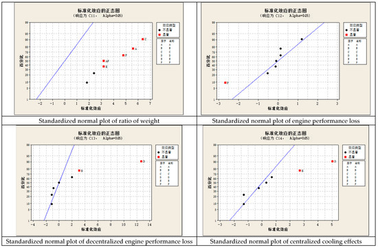
The normal plot of standardized effects for each X factor on the response is illustrated in Figure 8.
Figure 8.
Normal plot of standardized effects. Definition: 标准化效应正态图—Normal Plot of Standardized Effects; 百分比—Percentage; 标准化效应—Standardized Effect; 效应类型—Effect Type; 显著—Significant; 不显著—Not Significant; 响应为—Response; 因子—Factor; 名称—Name.
4.3. Program Optimization
Optimization of the design:
To achieve the optimal experimental effect, a multi-objective response optimization design is carried out for three effective response indicators—overall engine performance loss, decentralized cooling effectiveness, and centralized cooling effectiveness—based on the reliable second-order regression model established in the previous section.
The optimization objectives are set as follows: the overall engine performance loss and cooling effects are defined as a smaller-the-better characteristic (target interval: 0.37–0.40); decentralized and centralized cooling effectiveness are defined as larger-the-better characteristics (target intervals: 45.00–50.00 and 40.00–42.00, respectively), with an equal weight of 1 assigned to each indicator.
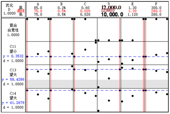
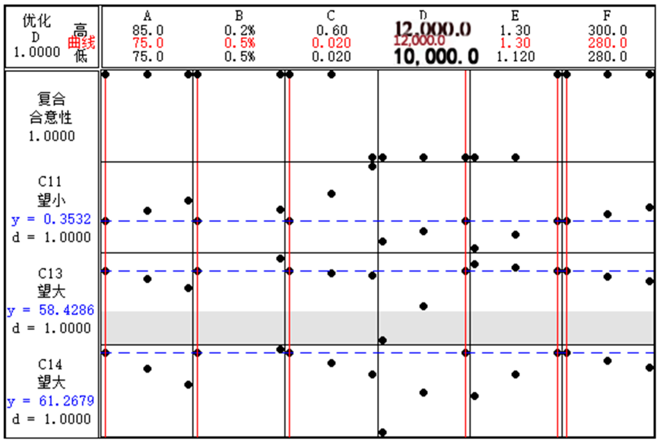
Since the performance loss falls within the expected range, cooling effectiveness is regarded as relatively more important. The global optimal solution is obtained with Minitab [29], and the optimal parameter combination is: A = 75 K, B = 0.5%, thermal conductivity of approximately 0.03 W/(m·K), D = 12,000 W, E = 1:0.3, F = 280 K.
Under this parameter combination, the predicted responses are: loss = 0.3532, C13 = 58.4286, and C14 = 61.2679. The desirability of each response reaches 1.000000, and the composite desirability is 1.000000, indicating excellent optimization performance. This result can provide a reliable parameter reference for practical engineering applications.
A standardized normal plot of Y1–Y4 response is shown in Figure 9.
Figure 9.
Standardized normal plot of Y response. Definition: 优化—Optimization; 高—High; 低—Low; 复合合意性—Composite Desirability; 望大—Larger-the-better; 望小—Smaller-the-better. 曲线: Curve.
Notes: The red vertical lines indicate the optimal factor levels (factors) for the best performance. The blue dashed lines represent the predicted response values under the optimal parameter combination. The gray shaded area denotes the target interval of the C13 response (larger-the-better characteristic). The composite desirability reaches 1.0000, confirming that all responses (C11: smaller-the-better; C13, C14: larger-the-better) fully meet the optimization objectives.
In the experimental design, the centralized average cooling temperature drop at the center point is 47 °C, while the optimized scheme achieves a cooling temperature drop of 61 °C, representing an improvement of 22%. Similarly, the decentralized cooling scheme shows an improvement of 26% and a 10% reduction in performance loss. In the DOE test, the functional relationship between influencing factors and responses was obtained by controlling the factor linear regression tool, and the optimal design scheme was obtained by parameter optimization [29].
In summary, the partial factorial experiment based on DOE efficiently solves engineering problems. In the DOE design, hypothesis testing is used to verify the reliability of the model, and the main influencing factors of the scheme are obtained simultaneously. On this basis, scheme optimization is carried out to achieve the optimal solution of the target response. Compared with the full factor test method, the sample data of the partial factor test method is reduced by 78%, which greatly saves the design cost and shortens the system design cycle.
It should be noted that in the current DOE-based optimization, the response surface model is a second-order approximation, which entails a certain degree of simplification for the strongly nonlinear thermal protection process.
In addition, the obtained optimal solution is statically optimal and thus cannot be directly applied to dynamic variable-temperature and variable-heat-flux conditions.
For transient problems, it is necessary to combine multiphysics simulations, multi-objective optimization, and dynamic optimization methods to further improve the engineering applicability.
5. Conclusions
This paper takes the research of obtaining a module thermal protection scheme of combined power as the research goal, and conducts research from thermal protection demand, protection scheme design to numerical simulation verification of protection scheme, respectively, and obtains some practical analysis models and meaningful conclusions:
- The integration of the active-passive thermal protection module and the centralized-decentralized cooling module effectively solves the TPS of accessories.
- The coupling between thermal protection modules, multi-scheme design and optimization of the TPS can be solved with DOE tools, and obtain the centralized-decentralized cooling flow rate, the temperature, and critical factors affecting the scheme. These can be boundaries for the subsequent design.
- The optimization scheme proposed in this paper is verified by numerical simulation. The optimized thermal protection system can effectively reduce the surface temperature of accessories, and all accessories meet the temperature requirements for long-term operation. Compared with the central point scheme that satisfies all design boundaries, the proposed scheme reduces cooling air consumption by 10% and improves cooling efficiency by 22–26%. The proposed engineering design method significantly shortens the development cycle and achieves a cost-saving rate of more than 78%.
- A modular active-passive integrated thermal protection design and optimization method suitable for accessories in combined power plants is proposed. Although the optimized scheme is case-specific, the design methodology and workflow have broad applicability. For instance, the characteristics of modular design—such as structural flexibility and convenient disassembly for engineering applications—can be applied to the thermal protection of existing engines with high structural inheritance. Furthermore, by introducing additional factors into the X parameters in the DOE design, entirely new optimized schemes can be obtained.
6. Prospect
- Flow characteristics of TPS and airflow leakage tests for centralized thermal protection and decentralized cooling systems, establishing databases. Current requirements for heat sinks in active cooling solutions exclude the premise of non-design gas leakage. Similarly, material specifications for passive cooling systems are formulated under this condition. Therefore, these testing criteria must be incorporated into the experimental item.
- In the thermal protection system design, this paper proposes two operational scenarios for maximum environmental temperatures of components. To meet subsequent engineering requirements, during detailed design phases, we recommend establishing stress-intensive, high-velocity flow, or service-life-focused design conditions that balance structural integrity and durability needs. These measures ensure the protective system operates safely in extremely high-altitude environments.
- The optimization scheme proposed in this paper is only targeted at TBCC power turbine accessories with different temperature resistances, and the optimization is performed within specific factor ranges, such as the given flow rate and temperature range of the cooling heat sink. But the thermal design and engineering optimization method presented in this paper can be applied to the thermal protection design of other engines. For instance, aiming at the potential insufficient stiffness and strength under hypersonic inflow conditions, as well as gap thermal control and damage tolerance analysis, the corresponding influencing factors and responses can be incorporated. Combined with the fluid–structure–thermal integrated coupling analysis model, the comprehensive performance of the enclosed cabin thermal protection system can be investigated, and the optimal design can be realized according to engineering requirements.
Author Contributions
Conceptualization, X.Y. and G.P.; methodology, C.Z.; validation, G.P. and C.Z.; formal analysis, G.P.; All authors have read and agreed to the published version of the manuscript.
Funding
This work was supported by the National Natural Science Foundation of China (NSFC) under Grant No. U2341278. The project title is “Coupling mechanism and its regulation of flow, heat transfer and chemical cracking of supercritical pressure hydrocarbon fuel and alcohol in micro-channels”. The principal investigator is Yu Xiao. This project focuses on active regenerative cooling technology to improve the thermal performance of advanced regenerative cooling systems, and the present paper reports part of the research results obtained from this project.
Data Availability Statement
The original contributions presented in this study are included in the article. Further inquiries can be directed to the corresponding author.
Acknowledgments
The authors have reviewed and edited the output and take full responsibility for the content of this publication.
Conflicts of Interest
The funders had no role in the design of the study; in the collection, analyses, or interpretation of data; in the writing of the manuscript; or in the decision to publish the results.
Abbreviations
The following abbreviations are used in this manuscript:
| TPS | Thermal Protection System |
| TBCC | Turbine-Based Combined Cycle |
| RBCC | Rocket-Based Combined Cycle |
| DOE | Design of Experiments |
References
- Li, C.J.; Yan, L.S.; Cui, H. Overview of thermal protection system technology for aerospace vehicles. High-Tech Fiber Appl. 2014, 39, 19–25+35. [Google Scholar] [CrossRef]
- Zhang, Q.D.; Lin, G.P.; Guo, J.H.; Liu, Z.Y. Modeling and Performance Research on Integrated Aircraft-Engine Thermal Management. Sci. Technol. Inf. 2023, 21, 49–53. [Google Scholar] [CrossRef]
- Zhou, Z.X.; Huang, J.Y.; Zhang, H.X.; Zhao, L. Development and Prospect of Thermal Control Technology for Chinese Spacecraft. Spacecraft Eng. 2023, 6, 1–9. [Google Scholar] [CrossRef]
- Xing, Y.J.; Su, B.; Gao, K.; Wang, Z.H.; Yang, Y. Research status of thermal protection system and heat-resistant materials for aerospace vehicles. Aerosp. Mater. Technol. 2018, 48, 9–15. [Google Scholar] [CrossRef]
- Zhang, S. Research on Thermal Management Method of Stamping and Combined Engine Based on Comprehensive Utilization of Cold, Heat and Electricity. Master’s Thesis, Harbin Institute of Technology, Harbin, China, 2019. [Google Scholar]
- Du, C.H. Research Progress on Integrated Thermal Management and Key Technologies of Hypersonic Vehicles. Equip. Environ. Eng. 2023, 1, 30–32. [Google Scholar]
- Bai, Y.F. Thermal Protection Scheme and Effect Analysis of Heat Storage Type High-Speed Vehicle Cabin. Master’s Thesis, Harbin Institute of Technology, Harbin, China, 2021. [Google Scholar]
- Wang, D.W. Design and Software Development of Thermal Insulation Tile Type Thermal Protection Integrated System. Master’s Thesis, Nanjing University of Aeronautics and Astronautics, Nanjing, China, 2020. [Google Scholar]
- Rastogi, A.K.; Rodi, W. Calculation of general three-dimensional turbulent boundary layers. AIAA J. 1978, 16, 151–159. [Google Scholar] [CrossRef] [Scilit]
- Wang, H.Z.; Li, J.; Qin, F.; Wei, X.G. Research on active and passive composite thermal protection scheme for BCC engine. Solid Rocket Technol. 2015, 38, 185–191. [Google Scholar] [CrossRef]
- Li, G.P. Research on Thermal Simulation and Air Cooling System of Series Hybrid UAV Power Cabin. Master’s Thesis, Chongqing University, Chongqing, China, 2023. [Google Scholar]
- Su, C.Y.; Lian, W.L.; Guo, J.; Ren, X.P. Performance analysis of integrated thermal management for aero-engine accessories. J. Aerosp. Power 2022, 37, 9. [Google Scholar] [CrossRef]
- Li, K.; Liu, Z.; Xu, J.; Liu, H.; Xu, S.; Wang, C.; Qin, J. Evaluation of High-Speed Aircraft Thermal Management System Based on Spray Cooling Technology: Energy Analysis, Global Cooling, and Multi-Objective Optimization. Appl. Therm. Eng. 2023, 229, 120632. [Google Scholar] [CrossRef] [Scilit]
- Wang, F.; Xu, J.L.; Wang, Y.S. Flow Field Characteristics of Modal Transition Process in Parallel TBCC Exhaust System. Exp. Fluid Mech. 2019, 3, 68–75. [Google Scholar]
- Zhao, X.S.; Zhang, X.X.; Yang, Z.B.; Cong, L.H. Study on Thermal Insulation Performance of a Thermal Protection Structure Under Thermal Shock Load. Eng. Test 2021, 4, 53–55+89. [Google Scholar] [CrossRef]
- Cao, Y.Z. Heat Transfer of Aero Engines; Beihang University Press: Beijing, China, 2005; pp. 10–16. [Google Scholar]
- Li, L.; Wang, Y.M. Research on Influencing Factors of Engine Cabin Cooling Test. Aeronaut. Sci. Technol. 2015, 29–32. [Google Scholar]
- Xue, S.Y.; Jia, Y.; Zhang, B.Q.; Xiang, Y.C.; Dai, C.H.; Wang, X.; Zheng, K. Design of nano-aerogel thermal insulation device and its application in Zhurong Mars Rover. Acta Aeronaut. Astronaut. Sin. 2022, 43, 626586. [Google Scholar]
- Mao, Y.F.; Li, Y.Z.; Wang, J.X.; Xiong, K.; Li, J.X. Cooling Ability/Capacity and Exergy Penalty Analysis of Each Heat Sink of Modern Supersonic Aircraft. Entropy 2019, 21, 223. [Google Scholar] [CrossRef] [Scilit] [PubMed]
- Liang, X.Y.; Liu, H.Y.; Bai, X.H.; Wang, Z.W.; Liu, C.L. Numerical simulation on cooling characteristics of corrugated plate heat shields with non-uniformly arranged cooling holes. Aeroengine 2023, 49, 26–31+2. [Google Scholar] [CrossRef]
- Tamunobere, O.; Drewes, C.; Acharya, S. Heat transfer to an actively cooled shroud with blade rotation. Am. Soc. Mech. Eng. 2014, 45721, V05BT14A021. [Google Scholar]
- Ye, J.S. Research on Thermal Simulation and Structural Layout of a Certain Type of UAV Piston Engine Cabin. Master’s Thesis, Chongqing Jiaotong University, Chongqing, China, 2025. [Google Scholar]
- Blosser, M.L. Advanced Metallic Thermal Protection Systems for Reusable Launch Vehicles. Ph.D. Thesis, University of Virginia, Charlottesville, VA, USA, 2000. [Google Scholar]
- Zhang, J.-C.; Wang, Y.; Zhang, C. Aerodynamic optimization design of multistage axial flow compressor based on DOE. J. Nanchang Hangkong Univ. (Nat. Sci.) 2012, 3, 16–21+47. [Google Scholar]
- Gunawan, S.S. Six Sigma-Based Quality Improvement in Aerospace Component Assembly. Int. J. Adv. Manuf. Res. 2025, 10, 1–15. [Google Scholar]
- Cui, J.H.; Yang, L.; Yan, Y.J.; Zhou, Y.Z. Application of DOE in aero-engine experiments. Eng. Test 2024, 4, 1–5+9. [Google Scholar] [CrossRef]
- Li, X. Application of Lean Six Sigma in Aero-Engine Manufacturing. In Advances in Aerospace Quality and Reliability Engineering; Zhang, Y., Wang, H., Eds.; Springer: Singapore, 2024; pp. 45–68. [Google Scholar]
- Smith, J.D.; Johnson, K.L. Six Sigma for Aerospace and Defense Manufacturing, 2nd ed.; ASQ Press: Milwaukee, WI, USA, 2023; pp. 120–159. [Google Scholar]
- Xu, D.J.; Zeng, B.H.; Li, W.M.; Chen, J. Application of 6Sigma orthogonal test in CAE dimensional accuracy optimization of side outer panel stamping. Mould Ind. 2021, 7, 7–12. [Google Scholar] [CrossRef]


Disclaimer/Publisher’s Note: The statements, opinions and data contained in all publications are solely those of the individual author(s) and contributor(s) and not of MDPI and/or the editor(s). MDPI and/or the editor(s) disclaim responsibility for any injury to people or property resulting from any ideas, methods, instructions or products referred to in the content. |
© 2026 by the authors. Licensee MDPI, Basel, Switzerland. This article is an open access article distributed under the terms and conditions of the Creative Commons Attribution (CC BY) license.