


Abstract
Conventional thermoelectric generators (TEGs) suffer from thermal resistance introduced by ceramic substrates and thermal interface materials, which limits the achievable temperature gradient across the junctions and reduces conversion efficiency. To overcome this limitation, a pin-fin integrated thermoelectric device (iTED) is proposed, in which the hot-side heat exchanger is incorporated directly into the hot-side interconnector, eliminating the ceramic and associated greases. An explicitly coupled thermal-fluid-electric finite-volume model is developed in ANSYS Fluent’s user-defined scalar (UDS) environment to quantify the simultaneous thermal-fluid-electric behavior of the iTED for inlet temperatures of 350 650, Reynolds numbers of 3000 15,000, and load resistances ranging from 0.01 to % of the internal device resistance (), for a fixed cold-side temperature of 300 K. The model is validated against established tube-bank correlations (2.2% agreement in pumping power) and a one-dimensional Explicit Thomson Model (1.2–6.9% agreement across all electrical system response quantities). Compared with an equivalently sized conventional TEG, the iTED achieves a 4.6-fold higher maximum power output (23.9 [W] vs. 5.2 [W] at Re = 15,000), a 2.8-fold higher thermal conversion efficiency (8.1% vs. 2.9%), and a 4.8-fold higher performance index (7.8 [-] vs. 1.6 [-] at Re = 3000), all at = 650 K. A performance index analysis reveals that lower Reynolds numbers and higher inlet temperatures maximize the net power benefit, delineating the operational envelope in which the iTED produces more electrical power than is needed for fluid pumping. These findings demonstrate that device-level restructuring—specifically, the elimination of interfacial thermal resistance via integrated pin-fin heat exchangers—can yield performance improvements comparable to or exceeding those achievable through material advances alone.
1. Introduction
Due to a growing environmental consciousness, efforts are being made to increase the efficiency of processes and cycles while simultaneously reducing greenhouse gas emissions. Thermoelectric devices (TEDs) are well-suited to waste heat-recovery applications, which can mitigate the adverse effects of fossil-fuel-based power generation and transportation. These two sectors are responsible for the vast majority of rejected thermal energy in the United States, which is a byproduct of fossil-fuel combustion [1]. Thermoelectric generators (TEGs), a subset of TEDs, are solid-state, direct energy conversion devices that capitalize on the Seebeck effect to convert a thermal gradient into an electric potential [2]. These devices are composed of periodic n- and p-type semiconductors connected electrically in series via electrically conductive bridges. The junctions are then exposed to a thermal gradient, which enables the flow of electrons. The materials within the TEG have a large Seebeck coefficient (), on the order of tenths of [mV ], high electrical conductivity (), and low thermal conductivity (), which helps maintain a large temperature gradient across the device [3,4]. The performance of the material, which subsequently dictates the device performance, is quantified by the figure of merit .
The modified dimensionless figure of merit represents the performance of a given thermoelectric material. The material performance is evaluated at the average temperature between the cold and hot junctions. A simpler approach evaluates the material’s performance at the absolute temperature T, yielding , the value most commonly reported in the literature. During the 1950s, semiconductors with higher thermoelectric performance ( 0.8) were developed, which aided in the development of devices with more favorable performance [5,6]. The introduction of nanostructures in the 1990s allowed for the development of materials with higher figures of merit, up to 1.7 [7]. Recently, materials have been shown to achieve a of 2.1, making TEGs more attractive for waste heat recovery applications [8]. Historically, bismuth telluride has been shown to be the optimal material for use at low temperatures, around room temperature [9,10,11]. At higher temperatures, i.e., 500–650 °C, lead tellurides have proven effective [9,12]. Skutterudites have also exhibited high figures of merit when operating at high temperatures [13]. Improvement in material efficiency is evidently vital for demonstrating the efficacy of TEGs for waste heat recovery applications. However, this is not the only consideration, as the design of the module proves comparably relevant.
The application of conventional TEGs to automotive waste heat recovery has been extensively studied; noteworthy and relevant works are discussed below. Kumar et al. developed numerical models to quantify the performance of conventional TEGs applied to the exhaust system of a passenger vehicle, including the thermal-hydraulic performance of the heat exchanger system and the electrical performance of the module. Their results indicated that increasing both the exhaust temperature and flow rates led to an increase in electrical power generation; however, this increase was limited by the heat transfer coefficient that developed. The maximum power output obtained was 552 W with a thermoelectric conversion efficiency of 5.50% and a system efficiency of 3.3% [14]. Further studies by Kumar et al. indicated that heat exchanger design was vital for favorable system performance. By constructing a heat exchanger that allowed for the transverse flow of exhaust gas across the modules, a maximum power output was achieved with a lower pressure drop, thus marginally increasing system efficiency [15]. Similarly, Sun et al. developed a mathematical model to quantify the performance of a two-stage TEG system applied to an internal combustion engine. In line with the findings of Kumar et al., they found that the TEG performance was directly dependent upon the waste heat temperature and flow rate, indicating that system performance depended on the thermal-hydraulic performance of the heat exchanger [16].
To facilitate waste heat recovery in automotive applications, efforts have been made to more effectively capture and convert the waste heat. The incorporation of heat pipes into a TEG waste heat recovery system has been studied. Heat pipes have the potential to reduce the thermal resistance between the exhaust gas and the TEG, effectively increasing the temperature difference across the TEG as well as decreasing the pressure loss in the system [17]. Kim et al. developed an experimental apparatus to investigate the use of TEGs and heat pipes for automotive waste heat recovery and found that a maximum power output of 350 W could be achieved [18]. Jia et al. demonstrated that internal baffles in solar air heaters can enhance convective heat transfer through increased turbulence and extended flow paths, yielding efficiency improvements of 10–40% over conventional designs [19]. The use of different metal foams on TEGs has also been investigated [20,21]. Nithyanandam and Mahajan studied a silicon carbide foam and the effects of pore density and porosity on the net power produced by a TEG. They found that the maximum net power was nearly eight times that produced by the same TEG without metal foam [20].
Although conventional TEGs have effectively been shown to convert the thermal energy of exhaust gas into usable electricity, thereby increasing system efficiency, there are still fundamental deficiencies. Inherent to the conventional TEG design is the presence of ceramic between the hot-side junction and the hot-side heat exchanger, which provides electrical insulation between the TEG and heat exchanger as well as structural support. The thermal resistance associated with the heat exchanger, but more importantly, the ceramic, decreases performance by effectively reducing the temperature difference across the junctions [22,23,24]. The thermal interface materials (e.g., greases and adhesives) used to make contact between the hot-side junction and ceramic, and between the ceramic and heat exchanger, diminish the temperature difference established across the junction, thereby decreasing performance [25]. Efforts have been made to overcome these resistances. Kim et al. constructed and tested a direct contact thermoelectric generator, as well as constructed a numerical model thereof, in which the hot-side heat exchanger of the TEG was removed, and the hot-side ceramic was placed directly in contact with the exhaust flow. They found that increased engine loads and speeds, which contribute to greater quantities of thermal energy at higher temperatures and the development of convective heat transfer coefficients, increased TEG performance, achieving up to 2% thermal conversion efficiency and 45 [W] of power output [26]. Although novel, the decreased heat exchanger surface area and lack of features that disrupt the formation of thermal and momentum boundary layers over the TEG surfaces prevent the system from experiencing a large temperature gradient. Ma et al. furthered the notion of the necessity to reduce thermal resistance between the heat source and sink by replacing the fins of the heat exchanger with thermoelectric material [27]. The work demonstrated the novel configuration and, more importantly, identified potential issues with actual implementation, namely the induction of large stresses in the TE material due to large stream-wise temperature variations. When considering the coefficients of thermal expansion for the TE material and metallic substrate, and the fact that the TE material is bonded to the substrate for a relatively large length (200 [mm] in this study), delamination or cracking would inevitably occur.
Recent advances in multiphysics modeling of TEGs have expanded the fidelity and scope of coupled numerical simulations. Luo et al. systematically compared separated and coupled thermal-fluid-electric modeling approaches, establishing that fully coupled models yield more accurate performance predictions, particularly under conditions of large temperature gradients and strong thermoelectric feedback [28]. The same group extended this work to transient conditions, developing hybrid CFD-thermoelectric models that capture the dynamic response of automotive TEG systems under realistic driving cycles [29,30]. Luo et al. further extended coupled thermo-electro-fluid modeling to thermoelectric cooling applications, developing a transient multiphysics model for a hybrid battery thermal management system that integrates thermoelectric coolers with vapor chambers and liquid cooling [31]. Chen et al. provided a comprehensive comparison of the applicable ranges of separated and coupled numerical models, offering guidance for model selection in waste heat recovery applications [32]. Wielgosz et al. developed a fully coupled three-dimensional finite-volume model in ANSYS CFX that accounts for Joule, Peltier, Thomson, and Bridgman heating with temperature-dependent material properties, demonstrating the importance of including all thermoelectric phenomena to achieve energy-balanced solutions [33]. In terms of heat exchanger design, Luo et al. demonstrated that diverging fin geometries can improve TEG performance through enhanced heat transfer uniformity [34], and Zhao et al. showed that pin-fin heat exchangers can increase net output power by over 400% when applied to solid oxide fuel cell exhaust recovery [35]. Chen et al. investigated the thermal stress implications of pin-fin arrays within TEG systems using evolutionary optimization [36]. Dashevsky et al. demonstrated high-reliability gas TEG designs with operating lifetimes of 15–20 years [37], while Vikhor and Kotsur evaluated the influence of electrical and thermal contact resistance on miniaturized thermoelectric converter efficiency [38]. These works collectively highlight the necessity of coupled multiphysics frameworks that simultaneously resolve the thermal, fluid, and electrical domains—precisely the approach adopted herein.
A promising solution for overcoming the thermal resistance of the ceramic and associated greases, as well as increasing the hot-side heat transfer while minimizing unnecessary thermally induced stresses, is the integrated thermoelectric device (iTED). This novel design allows for the elimination of the hot-side ceramic and greases by directly incorporating the hot-side heat exchanger into the hot-side interconnector. The exhaust gas flow is directed over the hot-side heat exchanger through a dielectric flow conduit. Through this modification, larger temperature gradients can be maintained across the junctions, and larger quantities of heat can be extracted from the waste heat stream. This study presents a thermal-fluid-electric coupled finite-volume model to study the effects of thermal-hydraulic parameters on this innovative design in comparison with a conventional design. The range of operational parameters, namely exhaust gas temperature and flow rate, is representative of those in on-road heavy-duty diesel vehicles [39], and extends previous analytical [40], numerical [41,42,43,44], and experimental [45] studies to the turbulent flow regime.
2. Materials and Methods
2.1. Integrated Thermoelectric Device Design
The pin-fin iTED is schematically depicted in Figure 1a. The pin fins serve two purposes. The first is to bridge the hot sides of the opposing p- and n-type materials, forming an electrical connection, such that the device operates electrically in series and thermally in parallel, as in a conventional TED. The second is to promote turbulence, specifically through the induction of vortex shedding, thereby promoting high heat transfer coefficients on the downstream pins, thus augmenting the hot-side junction temperatures and heat input. The pin fins are constrained by a dielectric flow channel that directs the hot fluid over the heat exchanger bank. Although the iTED operates like a conventional thermoelectric device, the restructured configuration eliminates the hot-side ceramic, which is typically used as an electrical insulator between the hot-side heat exchanger and the hot-side junctions, as shown in Figure 1b. Furthermore, there is no need for the grease used to minimize thermal contact resistance between the heat exchanger, the hot-side ceramic, and the hot-side junctions, which further diminishes the thermal resistance between the heat source and sink.
Figure 1.
Cross-sectional view of an (a) integrated thermoelectric device, showing the electrically in-series and thermally in-parallel p-n junctions, where the hot-side interconnector is incorporated into the hot-side pin-fin heat exchanger, as well as the dielectric flow channel (not modeled) directing the hot-fluid flow over the hot-side heat exchanger. There remains a dielectric material (e.g., ) between the cold-side interconnectors and the cold-side heat exchanger (not modeled). The channel height of , longitudinal pin spacing of , and a pin and rod diameter of are shown. (b) A conventional thermoelectric generator applied to waste heat scavenging. Note that the thermoelectric modules (TEMs) on the top and bottom of the flow channel have dielectric materials separating the cold- and hot-side interconnectors from the cold- and hot-side heat exchangers, respectively. The presence of the dielectric material between the hot-side interconnectors and hot-side heat exchangers constitutes in the conventional TED.
To demonstrate the efficacy of the iTED compared with a conventional device configuration, a favorable yet non-optimized heat exchanger configuration was selected. The pin-fin height-to-diameter ratio was set at five, as ratios greater than two have been shown to increase pin heat transfer for relatively low-Reynolds-number (Re) flow, i.e., up to 30,000 [46]. Additionally, by staggering the pins as depicted in Figure 2, convective heat transfer increases due to wake turbulence from upstream pins [47,48]. The iTED comprises 35 pins arranged in 10 rows, with the number of pins per row alternating between 3 and 4. To keep the transverse spacing, , between pins uniform in each row, corbels, or half-cylinders, were introduced on the walls of the dielectric flow channel for the row containing three pins, as shown in Figure 2.
Figure 2.
Top-down view of an integrated thermoelectric device, showing the transverse and longitudinal spacings, and , respectively, of the pin-fin heat exchanger, the packing density , the pin and pellet diameter D, and the flow channel width W. Top and bottom cold-side interconnectors are shown in gray for only the first two rows; the hot-side interconnectors are shown in white coloration.
As shown in Figure 1 and Figure 2, the proposed iTED has a flow-channel width W of 31.75 [mm] and a height H of 15.875 [mm]. The inlet Reynolds number is calculated based on the hydraulic diameter of the inlet, as opposed to the pin diameter. The pins and pellets have a diameter D of 3.175 [mm]. The transverse spacing and longitudinal spacing of the pins are 2.5D and 2D, respectively. Thus, the centerline-to-centerline length L of the pin array is 57.15 [mm]. The thermoelectric pellets and cold-side interconnectors are assumed to be 1 [mm] thick. This configuration reflects a device with 35 pin fins, p-n junctions, and 36 cold-side interconnectors. Based on and , the packing density , or the area of thermoelectric material per unit area of the device, is 15.7%.
2.2. Finite-Volume Domain Generation
The numerical domain representing the conventional and integrated thermoelectric devices was constructed in ANSYS ICEM (Version 17.2). Hexahedral elements were constructed in a highly orthogonal, conformal manner to create a non-uniform, structured mesh. Within the fluid domain, an inflation layer was constructed on all solid surfaces that interfaced with it, ensuring that the maximum , based on the highest Re and inlet temperature (), was globally sub-unity. The solid domains, which comprise the copper pins and interconnectors and the n- and p-type thermoelectric materials, are shown in Figure 3. The coarse mesh for a rod, thermoelectric pellets, and interconnector is shown overlaid. A detailed view of the working fluid domain, complete with insets demonstrating the refinement around the pin fins, is presented in Figure 4.
Figure 3.
Depiction of the solid domains within the iTED; the mesh is overlaid on the pin-fins, pellets, and cold-side interconnectors.Note that all top and bottom surfaces of the upper and lower interconnectors are kept at a constant cold-side temperature of 300 K.
Figure 4.
Mesh of the fluid domain, with top-down views of the coarse (13,793,220 control volumes), medium (30,827,174 control volumes), and fine (69,190,554 control volumes) density grids (considering the solid domain as shown in Figure 3).
2.3. Governing Equations
The concurrent characterization of the fluid domain’s thermal-hydraulic behavior and the resultant thermal-electric response within the solid domains of the conventional and integrated thermoelectric devices required a unique iterative solution algorithm. Thus, a thermal-fluid-electric field model was implemented in ANSYS Fluent (Version 17.2) using the C-based UDS environment. The thermal-fluid behavior of the fluid and solid domains was solved using Fluent’s standard flow and energy solvers, respectively, whereas the thermoelectric phenomena within the solid domains were resolved using UDSs. The Joule, Thomson, and Peltier heats were calculated based on the temperature distributions within the solid domains, as obtained by the standard energy solver, and then coupled to the general energy transport equation via volumetric and surface source terms. The aforementioned three source terms were applied to the thermoelectric solid domains, whereas only Joule heating was applied to the non-thermoelectric solid domains. The electric fields, specifically the Seebeck electromotive force (SEMF) and electric potential (EP), were calculated within the UDS and modeled via diffusion equations. The internal electrical resistance was also calculated via a volume-weighted sum of each element’s resistance within each domain. This methodology employs an explicitly coupled scheme that enables the simultaneous resolution of the thermal-fluid-electric behavior of both conventional and integrated thermoelectric devices.
As in previous works by the authors [41,42,44,49], which have been validated in prior studies [33,50], the following solution methodology is implemented to couple the thermal and electric governing equations. The explicit UDS expressions and their implementation within the ANSYS Fluent environment follow the formulations presented by Chen et al. [50]. The UDS source files used within this study are publicly available on GitHub (https://github.com/mmb49/MDPI---Multiphysics-Modeling-of-an-Integrated-Thermoelectric-Generator). The pertinent governing equations for the fluid and solid domains, and the respective boundary conditions, are discussed below.
2.3.1. Fluid Domain
The thermal-fluid behavior of the fluid domain was investigated using a finite-volume discretization of the governing continuity, momentum, and thermal energy transport equations, solved on the aforementioned mesh, which represents the numerical domain. To model the turbulent phenomena present within the specified flow regime, the Reynolds-averaged Navier–Stokes (RANS) continuity, momentum, and thermal energy transport equations were employed. Considering the steady flow of a Newtonian fluid, the continuity equation, Equation (1), and the momentum equation, Equation (2), are expressed as follows:
The total thermal energy transport equation, due to turbulence, is expressed as Equation (3):
During the process of constructing the RANS conservation equations, two closure terms arise within Equations (1) and (2), known as the Reynolds stress tensor and turbulence heat flux. These two terms result from the fluid’s turbulent behavior and must be accounted for using an additional set of conservation equations. To this end, the model was employed to provide the necessary closure.
The application of Equation (2) requires four boundary conditions: one for each velocity component and one for pressure. The inlet Reynolds number is defined using the hydraulic diameter of the inlet cross-section as:
where is the fluid density, V is the mean inlet velocity, is the hydraulic diameter of the inlet, and is the dynamic viscosity. At the inlet of the fluid domain, Re values ranging from 3000 to 15,000 in increments of 3000 were applied; the mean inlet velocities ranged from ≈2.93 [m/s] at the lowest Re and values to ≈42.4 [m/s] at maximum Re and values. At the exit of the fluid domain, a zero-gauge pressure outlet boundary condition was applied. For all interior surfaces of the fluid domain, i.e., all channel walls and fluid-rod interfaces, a no-slip boundary condition was applied. The application of Equation (3) requires two boundary conditions. The first was applied at the inlet, where the fluid inlet temperature was varied between 350 and 650 K, in increments of 50 K. The second thermal boundary condition was applied at the cold side of the interconnectors, where a constant temperature of 300 K was maintained. The fluid-rod interfaces were modeled with a conservative heat flux condition. The aforementioned conditions, which reflect the thermal-hydraulic behavior of heavy-duty diesel-powered vehicles, provide 35 unique operational points for both the integrated and conventional devices.
2.3.2. Solid Domains
The solid domains, thermoelectric and non-thermoelectric, were each governed by a unique thermal equation. The thermoelectric material domains, i.e., n- and p-type materials, were governed by the thermoelectric general energy equation, Equation (5), which is expressed as:
The second and third terms in Equation (5) represent the Joule and Thomson heats, respectively, and were modeled using volumetric source terms. The fourth term represents the Peltier heat, and was modeled as a surface source term. Within the UDS framework, the current density is expressed as , where is the electrical conductivity stored as the diffusivity for the electric potential UDS. The Joule, Thomson, and Peltier source terms from Equation (5) are implemented within the energy equation as follows. The Joule heating source term, applied as a volumetric source to both thermoelectric and non-thermoelectric solid domains, is expressed as:
The Thomson heating source term, applied as a volumetric source exclusively within the thermoelectric material domains, is expressed as:
where is the Thomson coefficient, evaluated analytically from the temperature-dependent Seebeck coefficient polynomials listed in Table 1. The Peltier heating source term, applied as a surface source at the interfaces between the thermoelectric materials and interconnectors, is expressed as:
where denotes the gradient of the Seebeck coefficient field at the material interface. The distinction between volumetric (Equations (6) and (7)) and surface (Equation (8)) application is physically motivated: Joule and Thomson effects are distributed phenomena occurring throughout the bulk of the thermoelectric material, whereas the Peltier effect arises at junctions where the Seebeck coefficient changes discontinuously between dissimilar materials.
Table 1.
Polynomial expressions for the temperature-dependent thermoelectric properties of n [51]- and p-type [52], copper, alumina [53], and air [54] materials used in the numerical calculations. All polynomial fits are valid from 300 to 650 K.
The six user-defined scalar fields employed within the UDS framework, their physical representations, and the domains to which they are applied are summarized in Table 2. Similarly, the energy source terms, their corresponding UDS formulations, and domain assignments are summarized in Table 3.
Table 2.
User-defined scalar (UDS) field definitions and domain assignments within the ANSYS Fluent framework.
Table 3.
Energy source term implementations within the UDS framework, showing the governing expression from Equation (5), the corresponding UDS formulation, source type, and domains of application. TE denotes thermoelectric material domains (n- and p-type); non-TE denotes interconnectors and pin fins.
It should be noted that the Peltier and Thomson source terms (Equations (8) and (7)) are mathematically equivalent within the bulk of a homogeneous thermoelectric material, because when . Accordingly, only one of the two formulations should be applied as a volumetric source to the thermoelectric domains to avoid double-counting; the present implementation employs Joule and Thomson volumetric sources exclusively.
The non-thermoelectric domains, i.e., hot-side heat exchangers and cold-side interconnectors, were governed by the general energy transport equation, Equation (9), such that:
Both thermoelectric and non-thermoelectric domains were also governed by the continuity of electric current, Equation (10), expressed as:
To simultaneously couple the thermal and electrical governing equations, the current density vector , as determined by the open-circuit voltage magnitude, , and internal resistance, , is used within Equations (5), (9), and (10). The , commonly referred to as the Seebeck voltage, is calculated as the sum of the open-circuit voltage potentials of each thermoelectric pellet at its respective interfaces between the pin and interconnectors, such that:
Then, the of the device is calculated as:
Therefore, the magnitude of the current density, based upon Equations (11) and (12), which is applied to the outlet terminal, is calculated as:
The electric potential is expressed through the non-Ohmic voltage-current relation [55], and was modeled as a diffusivity within the UDS environment throughout the thermoelectric and non-thermoelectric solid domains. The Seebeck electromotive force, or the second term in the second expression below, was also modeled as a diffusivity within the UDS environment, but only in the thermoelectric domains. Thus, the non-Ohmic voltage-current relation is expressed as follows:
Substituting the current density relation into Equation (10) and employing Equation (14), the electric potential field is governed by:
where the right-hand side represents the Seebeck electromotive force (SEMF) source term. Within the UDS framework, serves as the diffusion coefficient for the electric potential scalar, and the SEMF is resolved via an auxiliary scalar field whose source is computed from the gradient of , following the methodology of Chen et al. [50].
At the inlet terminal, a zero-voltage potential is applied such that:
The remaining boundaries of the system are treated as electrically insulated, such that:
At the interfaces of the hot-side interconnectors, pellets, and cold-side interconnectors, the continuity of current density is applied, such that:
Thus, the current, as well as the electric potential, develops implicitly as part of the solution. As for the thermal boundary conditions, the bottom and top surfaces of the bottom-side and top-side interconnectors are maintained at a constant temperature of 300 K, yielding:
The exterior surfaces of the pellets and interconnectors are exposed to ambient convective conditions, such that:
The ambient fluid temperature is kept constant at 300 K, and the convective heat transfer coefficient is also kept constant at 10 [W ]. The inlet and outlet terminals are assumed adiabatic, such that:
At the interfaces between the hot-side interconnectors, pellets, and cold-side interconnectors, continuity of temperature and heat flux is imposed, yielding the following:
The electrical power output is determined from the quotient of I squared and , where is equal to to maximize power output, such that:
Additionally, is varied between 0.01 and % of , and the variation of I, , , , , , , and is presented.
The heat removed from the fluid and transferred to the conventional and integrated thermoelectric devices, , is a function of the mass flow rate, specific heat, and the temperature difference between the inlet and exit. The mass flow rate is calculated as the product of the inlet cross-sectional flow area, velocity, and density, evaluated as the integral average between the inlet and exit temperatures. The specific heat, as reported by [56], is also evaluated as the integral average between the inlet and exit temperatures. Lastly, the temperature difference between the inlet and exit of the fluid domain is calculated from area-averaged values. Thus,
The device thermal conversion efficiency, , is a function of the electrical power output per the summation of the heat input and pumping power, :
The pumping power was evaluated as the inlet velocity times the inlet cross-sectional area, which is equivalent to the mass flow rate per unit density, times the difference between the area-averaged pressures at the inlet and exit of the fluid domain:
To quantify not only the electrical power output and efficiency of the devices, but also a performance index, is introduced as the ratio of the electrical power output to pumping power, minus unity. It is desirable to have above naught, indicating that the device is producing more power than is required for operation:
2.4. Numerical Considerations
Within Equation (2), the SIMPLE algorithm was used to couple pressure and velocity. Within Equations (2) and (3), a second-order accurate upwind scheme was used to model the advective discretization of the transport expressions. Likewise, second-order accurate discretization schemes were used for pressure, as well as the thermoelectric phenomena expressed in Equation (5). The gradients of all pertinent field variables were calculated using a Gauss-cell-based scheme. All UDSs within the thermoelectric domain were modeled using a power-law scheme. The residuals for all conservation equations (continuity, momentum, and total energy), as well as electric potential and current, as defined by the UDS, were set to a convergence criterion of .
In the finite-volume model, all pertinent variables were treated as temperature-dependent. That is, all thermophysical properties of the solid and fluid domains were modeled with temperature-dependent polynomial fits, which are presented in Table 1.
2.5. Grid Independence
A grid independence study was conducted on the three generated meshes. The coarse, medium, and fine meshes contained 13,793,220, 30,827,174, and 69,190,554 control volumes, respectively. The grid independence study was conducted at inlet conditions of Re = 15,000 and = 650 K, for both the conventional and integrated designs, and the results are shown in Table 4. It is evident that, through the refinement process between the medium and fine meshes, the percent difference in values does not exceed 1% for all configurations and materials, clearly indicating that a grid-independent solution was obtained. That is to say, all values are either monotonically increasing or decreasing, rather than oscillating, i.e., converging to a value. Additionally, to obtain the numerical uncertainty in the fine-mesh values, the Grid Convergence Index (GCI) was calculated from all three levels of mesh refinement, following the procedure outlined by Celik et al. [57]. It is evident that the process of discretizing the governing equations into finite-volume form and refining the mesh leads to very small errors associated with most of the electrical SRQs; the highest uncertainty occurs in calculating the heat input into the hot-side junctions of the pellets, with the conventional device exhibiting a 21.8% uncertainty, which is roughly three times the uncertainty associated with the same variable in the iTED model. All results reported herein are obtained using the medium mesh.
Table 4.
Grid independence study for coarse (13,793,220 control volumes), medium (30,827,174 control volumes), and fine (69,190,554 control volumes) meshes for the inlet conditions of Re = 15,000 and = 650 K for both the integrated and conventional device configurations using . Reported absolute percent differences are between the medium and coarse meshes and the fine and medium meshes. The numerical uncertainty of the solutions from the fine mesh is provided as determined by the GCI.
2.6. Comparison to Conventional TEG
Previous studies have shown that the inclusion of a ceramic substrate and the necessary greases to affix the substrate to interconnectors and heat exchangers in a conventional thermoelectric device reduces performance. These components, although necessary to provide electrical insulation between the thermoelectric module and heat exchanger, introduce a thermal restriction between the heat source and sink, which in turn reduces the achievable temperature difference across the junctions, as well as the heat input into the device. The thermal resistance of the ceramic, which is represented as a contact resistance between the hot-side pin-fin heat exchanger and the hot sides of the n- and p-type pellets, is expressed as:
The ceramic substrate’s thickness, , is set to 1 [mm], reflecting the typical geometry found in commercial devices. The thermal conductivity is expressed as a temperature-dependent polynomial fit generated from data provided by [53]. The area is the unit area of the device, i.e., times . Thus, depending on the established temperature difference across the ceramic substrate, the thermal resistance values could range between 0.538 and 1.4 [K/W]. The thermal resistances of adhesives [25] and ceramic support materials [23,24] have been shown to decrease the temperature gradient across the device, thereby reducing overall efficiency.
By comparing the performance of the integrated configuration with that of a conventional thermoelectric device, the improvement in device performance can be quantified. Therefore, the conventional configuration is additionally modeled under all inlet fluid temperatures and Reynolds numbers to provide a direct basis of comparison with the integrated configuration.
3. Results and Discussion
The effects of flow rate, quantified by the Reynolds number (3000 15,000) and hot-side inlet temperature (350 K ≤ 650) on the thermal-fluid-electric performance of both the iTED and the conventional TED, namely internal resistance (), developed open-circuit voltage (), current (I), power (), and subsequent device efficiency () considering heat input () and pumping power (), as well as the dimensionless performance index (), are presented. Furthermore, the effect of load resistance () on a select operating condition is considered by varying between 0.01 and % of the iTED’s internal resistance value.
3.1. Validation
Within the following sections, pieces of the numeric model will be validated against analytic predictions and experimental correlations.
3.1.1. Hydraulic Characteristics
To validate the numerical model’s thermal-electric-hydraulic predictions, we will first compare the pressure drop predictions against established empirical correlations for staggered tube banks, following the methodology of Žukauskas [58] and presented within [59].
The calculation is performed at the grid-independence-study conditions: and K. Given the inlet cross-sectional area and temperature-dependent thermophysical properties, the inlet velocity is calculated to be 42.41 [m/s]. For a staggered pin-fin arrangement, the maximum velocity may occur at the transverse or diagonal plane between the pin fins. The diagonal pitch is given as follows:
Checking the criteria of , the maximum velocity occurs at the transverse plane, which results in a maximum velocity of the following:
It should be noted that the , as calculated using the Žukauskas methodology, reflects the bulk mean velocity flowing through each gap between two fins. The Reynolds number associated with the maximum velocity, considering a characteristic length of D, is thus 3752 [-]. The friction factor f is thus approximately 0.35 [-], and the correction factor is approximately 1.0 [-]. Thus, the pressure drop across the pin-fin tube bank is as follows:
The pumping power can alternatively be expressed as follows:
Consulting Table 4, the pumping power for the fine mesh was found to be 96.901 [W], which corresponds to a 4.06% difference from the predicted value under the maximum operating conditions (i.e., the highest flow rate and temperature). This level of agreement confirms that the finite-volume model accurately captures the hydraulic behavior of the pin-fin array. Several factors account for the small differences between numerical and empirical predictions: (1) the empirical correlation assumed an infinitely wide tube-bank, whereas the numerical model has side walls and corbels; (2) the empirical correlation was developed for constant-property flows, whereas the numerical model employs temperature-dependent fluid properties; and (3) inlet and exit effects are not present in the empirical correlation.
To further validate the hydraulic characteristics, the average transverse velocities of the fine mesh at each row of pins were compared to those calculated using the Žukauskas methodology, and further to those found through conservation of mass. For each row of pins, the area-averaged velocity was calculated in ANSYS CFD-Post (as shown in Figure 5) and is reported in Table 5; uncertainty in the average transverse velocity was calculated using the GCI and is shown in the same table. As seen in Figure 5, the wall velocities are zero, and the maximum velocities occur near the interior pins as the fluid is accelerated through the reduced cross-sectional flow area. It is also evident that the pins downstream of the first-row turbulators (i.e., Row 2) experience an increase in average velocity, thereby promoting heat transfer. Thereafter, the average velocities monotonically decrease.
Figure 5.
Area-averaged transverse plane velocities for Re = 15,000, = 650 K fine mesh case.
Table 5.
Row-wise average velocities for the pin-fin structure as predicted by numerical (ANSYS Fluent) and analytical methods (conservation of mass). Relative percent differences are reported relative to the numerically calculated velocities. Recall that the Žukauskas methodology predicts row-wise velocities of 70.68 [m/s].
The uncertainty associated with the numerically calculated values was found to be a minimum of 0.030% (Row 1) and to increase monotonically to a maximum of 4.29% (Row 10). For eight of the ten rows, the average transverse velocity, as calculated by the Žukauskas methodology, of 70.68 [m/s], fell within the numerical model’s uncertainty bounds. For the remaining rows (1 and 2), the empirical correlation value falls only slightly outside the numerically predicted ranges. This slight difference can be attributed to the same factors used to explain the differences in pumping power.
A second validation method was based on the conservation of mass through the iTED. At the inlet, the mass flow rate was calculated as follows:
Considering the conservation of mass at each plane intersecting a row of pins, the velocity for each row for , was then calculated:
When these values were compared to those from the fine mesh, as shown in Table 5, the maximum relative error was 0.942%, and the minimum was 0.345%. Given the model’s performance in these two comparison methods, the authors are confident that it satisfactorily resolves the hydraulic behavior of the fluid flow in the channel.
3.1.2. Thermoelectric Phenomena
To validate the thermoelectric performance predicted by the finite-volume model, a one-dimensional Explicit Thomson Model (ETM) [60] was constructed for the 35-unicouple iTED device. The ETM provides an analytic framework for computing the thermal and electrical performance of the device using Dirichlet boundary conditions extracted from the numerical model at the thermoelectric element junctions.
For each couple i (), the hot- and cold-side junction temperatures of the n- and p-type thermoelectric elements, denoted , , , and , respectively, are prescribed from the solution of the numerical model. The temperature-averaged and temperature-integrated material properties for each element are defined as follows:
where represents the temperature-dependent material properties (i.e., , , , and ). Since the 35 unicouples are connected electrically in series, the total open-circuit voltage (Seebeck voltage) is the sum of the per-couple contributions as described by Gassler et al. [61]:
The total internal electrical resistance is given as:
where and are the electrical resistances associated with the hot- and cold-side interconnectors, respectively, evaluated at their average junction temperatures.
Because each unicouple is operating under a different temperature difference, each couple has a different internal resistance and generates a different Seebeck voltage. Following the methodology of Gassler et al. [61], the current through the series circuit is enforced via continuity and iteratively solved for. The output voltage across the device (or external load) is given as:
and the current at iteration is updated as:
where and are evaluated using integral-averaged material properties at iteration k. The iteration proceeds until the absolute change in current satisfies amperes.
As defined within the ETM, the heat entering the hot-side junction of the n-type element in each couple is given as:
where is the integrated-average thermal conductance, and the Seebeck coefficient in the Peltier heat term is evaluated at the local junction temperature. An analogous expression for the p-type elements can be constructed and holds true. The total device heat input and electrical power are defined as:
The system-level thermal conversion efficiency and performance index (Equations (25) and (27)) can then be calculated.
The junction temperatures prescribed within this analytic model were extracted from the numerical model, which had active thermoelectric coupling enabled and for which the load resistance was set equal to the internal resistance to maximize power output. These temperatures are supplied as Dirichlet boundary conditions within the ETM; the model independently computes the Seebeck voltage, internal resistance, and current, given the material properties and geometry. As such, the SRQs, such as internal resistance, Seebeck voltage, current, heat input, power output, pumping power, thermal conversion efficiency, and performance index, constitute the validation targets.
Table 6 presents the predicted values from ANSYS Fluent (fine mesh) and the ETM. Percent differences are calculated relative to the fine-mesh numerical solution. The ETM predicts the internal resistance to within 1.24% of the fine-mesh numerical data and subsequently calculates the Seebeck voltage to within 2.75%, yielding a current within 4.04% of the numerical model. These values form the basis for subsequent SRQ calculations. The electrical power output agrees within 6.91% with the numerical data, and the performance index agrees within 2.15%.
Table 6.
Solid-domain validation of the 35-unicouple iTED at Re = 15,000 and = 650 K. The ETM uses Dirichlet boundary conditions extracted from the fine-mesh numerical model. Percent differences are computed with respect to the fine-mesh.
The heat input rate and thermal conversion efficiency evaluated at the ETM matched-load current are not directly comparable to the Fluent values because the ETM current (17.165 [A]) differs from the self-consistent CFD current (16.498 [A]), producing different Peltier and Joule contributions. To isolate the thermal model fidelity from this current mismatch, is additionally evaluated in a conduction-only state, i.e., I = 0 [A], where all thermoelectric coupling terms vanish, and the heat transfer reduces to pure Fourier conduction through the thermoelectric elements.
The resulting = 238.592 [W] agrees with the numerical data to within 4.59%, and the discrepancy is attributable to the one-dimensional conduction assumption in the ETM versus the three-dimensional conjugate heat transfer resolved by the finite-volume model. An approximate system-level efficiency constructed from the matched-load electrical power and the conduction-only heat input agrees with the CFD to within 3.51%.
3.2. Numerical Results
The following subsections present the full numerical characterization of the iTED and conventional TED, as well as comparisons between the two device structures.
3.2.1. Average Hot-Side Temperature
The entire thermoelectric performance of the integrated and conventional devices is determined by the temperature difference across the junctions. Figure 6 portrays the average hot-side temperature, , of the junctions of the integrated and conventional devices. It is once again noted that the cold-side temperature of both the integrated and conventional devices is held constant at 300 K and that no thermal resistance exists between the cold-side interconnector and the heat sink, providing a basis for comparison. With the inclusion of thermal resistance between the hot-side interconnector and the pin, which simulates the presence of ceramic between the hot-side interconnector and the thermoelectric material, the average hot-side junction temperature is substantially lower in the conventional device than in the integrated configuration. Without thermal resistance (i.e., in the integrated device), the hot-side junction temperature asymptotically approaches a value less than, but near, the free-stream temperature as the Reynolds number increases. This trend is most evident at the higher inlet temperature conditions. With the thermal resistance, this trend persists in the conventional device; however, the offset is more pronounced. For instance, at a Re of 15,000 and an inlet temperature of 650 K, the average hot-side temperature of the iTED is 570.8 K, whereas that of the conventional device is 451.9 K. Thus, the ceramic plate used to separate the hot-side heat exchanger from the hot-side interconnectors markedly diminishes the attainable temperature gradient across the junctions, and as will be shown, the performance of the device.
Figure 6.
Average hot-side junction temperature, , for the integrated (solid line) and conventional (dashed line) devices for all Re and conditions.
The non-linear interaction of the fluid with the pin, both in terms of momentum and heat transfer, and the non-linearity associated with heat entering the junctions, do not lend themselves to a simple relation between thermal resistance and an established temperature gradient. As the Reynolds number increases, the average hot-side temperature asymptotically increases under all inlet temperature conditions, due to the development of a larger convective heat transfer coefficient. For example, for a fixed inlet temperature of 650 K, increasing the Reynolds number from minimum to maximum (a factor of five) increases the average hot-side temperature by factors of 1.38 and 1.22 for the integrated and conventional devices, respectively. As the inlet temperature increases for a fixed Reynolds number, there is an observed near-linear increase in the average hot-side temperature. This increase is more substantial than that from increasing the Reynolds number. For example, increasing the inlet temperature from 350 to 650 K (a factor of 1.86) for a Reynolds number of 15,000 results in an increase in the average hot-side junction temperature by factors of 5.14 and 3.98 for the integrated and conventional devices, respectively. Thus, in terms of establishing the largest permissible temperature gradient across the junction, it is desirable to have the highest Reynolds number and inlet fluid temperature. However, as will be shown, this does not necessarily yield the best device performance.
Figure 7a,b depict the temperature distribution within the solid domains. From Figure 7a, it is evident that there is a minimal temperature difference across the cold- and hot-side interconnectors; the greatest temperature difference exists across the thermoelectric pellets. From Figure 7b, it can be seen that the first row of pins within the iTED has a lower temperature (averaging 584.19 ± 0.38 K) compared to the second row (averaging 588.45 ± 0.51 K); thereafter, the temperature of the pins begins to decrease along the direction of flow. The last row experiences the lowest average temperature of 569.72 ± 1.57 K. The conventional TED experiences the same pattern; however, the temperatures are higher. The first, second, and last rows had average temperatures of 606.64 ± 0.19 K, 609.97 ± 0.24 K, and 600.59 ± 1.04 K, respectively.
Figure 7.
Surface temperatures of the hot-side interconnectors (i.e., pin fins) of the conventional and integrated thermoelectric devices Re = 15,000 and = 650 K. (a) A three-dimensional rendering of the pin-fin array, thermoelectric pellets, and cold-side interconnectors. (b) A top-down view of the mid-plane hot-side interconnectors (i.e., pin fins) illustrating the row-to-row temperature variation. Note: Two different color scales are used to resolve the spatial variation within each design.
Although surface temperatures of the pin fins within the conventional device operate at a higher temperature than those in the iTED, the thermal resistance of the dielectric ceramic () between the hot-side interconnector and thermoelectric material causes a substantial temperature drop (>120 K) across the simulated ceramic. This, in turn, drastically reduces the hot-side junction temperature and the achievable temperature difference across the thermoelectric material.
Figure 8a,b depict the mid-plane fluid temperature and velocity contours for the conventional and integrated device configurations, respectively. From Figure 8a, it can be seen that the conventional device retains higher air temperatures farther down the pin-fin array than does the iTED; the simulated ceramic introduces a large thermal resistance between the pin fins and the hot-side junction of the thermoelectric materials. The iTED enables more effective heat extraction through direct thermal contact between the fluid and the hot-side interconnectors, as evidenced by the more pronounced streamwise temperature differences. This behavior is consistent with the higher heat input values seen in Figure 15 in Section 3.2.7.
Figure 8.
Mid-plane contours of the fluid domain for the conventional (top) and integrated (bottom) thermoelectric devices at Re = 15,000 and . (a) Temperature distributions illustrating the streamwise cooling of the inlet fluid. (b) Velocity magnitudes depicting regions of low- and high-velocity regions and acceleration through the transverse gaps between pins and the subsequent downstream wake structures.
From Figure 8b, the velocity fields appear qualitatively similar, with both exhibiting flow acceleration through the transverse gaps and the presence of recirculation zones downstream of the pins. The wake structures behind the pins are prominent, enhancing downstream pin heat transfer. The similarity of the velocity fields of both devices aligns with the near-identical pumping power requirements, as will be discussed in Section 3.2.6.
3.2.2. Internal Electrical Resistance
As the hot-side temperature increases, evaluating the internal electrical resistance of the solid domains becomes feasible. Figure 9 depicts the behavior of the internal electrical resistance, , with increasing Reynolds number and inlet fluid temperature for both the integrated and conventional designs. With increasing inlet temperature and Reynolds number, the internal device resistance decreases non-linearly; however, the rate of decrease diminishes once the inlet temperature exceeds 500 K. Although the electrical resistivity of the copper pins and interconnectors increases nearly linearly with temperature, the n- and p-type materials exhibit decreasing electrical resistivity up to 500 K, after which these values increase. Since the electrical resistivity of the thermoelectric materials is three orders of magnitude greater than that of copper, these values dictate device behavior. The electrical resistivity of the integrated device decreases to a greater extent over the range of inlet temperatures than that of the conventional device, due to its higher average hot-side junction temperature.
Figure 9.
Variation in internal electrical resistance with inlet flow rate, Re, and inlet fluid temperature, , for the integrated (solid line) and conventional (dashed line) thermoelectric devices.
3.2.3. Seebeck Voltage
The evolution of the Seebeck voltage, , with respect to Reynolds number and inlet temperature is shown in Figure 10 for the integrated and conventional designs. Since the Seebeck voltage is directly proportional to the temperature difference established across the junctions, the trends in Figure 10 follow those shown in Figure 6. With increasing Reynolds number, the convective heat transfer coefficient increases, a greater temperature difference is established across the junctions, and the Seebeck voltage subsequently increases in magnitude. Although increasing the Reynolds number increases the Seebeck voltage, this relation is not without limitation; for this particular pin-fin configuration, the convective heat transfer coefficient increases proportionally to the Reynolds number to the sixth-tenths power [58]. Accordingly, increasing Re by a factor of five for a fixed inlet temperature of 650 K increases the Seebeck voltage by factors of 1.60 and 1.31 for the integrated and conventional devices, respectively.
Figure 10.
Variation in with inlet flow rate, Re, and inlet fluid temperature, , for the integrated (solid line) and conventional (dashed line) thermoelectric devices.
Increasing the inlet temperature has a more pronounced effect on the Seebeck voltage than increasing the Reynolds number. For a fixed Reynolds number of 15,000, increasing the inlet fluid temperature from a minimum to a maximum value increases the Seebeck voltage by factors of 11.73 and 9.98 for the integrated and conventional devices, respectively. Increasing the inlet fluid temperature results in a monotonic increase in the average hot-side temperature and the Seebeck voltage, whereas increasing the Reynolds number results in asymptotic increases in both. It is evident that applying the proper thermal and flow conditions, as well as the proper heat exchanger geometry for these thermal-hydraulic conditions, to allow the most favorable temperature gradient to develop and thereby maximize the thermoelectric material performance, results in optimal performance. Compared with the conventional design, the integrated device unequivocally produces a larger Seebeck voltage across all Reynolds numbers and inlet fluid temperature values. For instance, at a Reynolds number of 15,000 and an inlet fluid temperature of 650 K, the Seebeck voltage of the integrated device is 2.01 times greater; at an inlet fluid temperature of 350 K, this factor of increase drops to 1.69.
Figure 11 depicts the development of the Seebeck electromotive force (SEMF) and Ohmic voltage, respectively, for a Reynolds number of 15,000 and an inlet fluid temperature of 650 K. The SEMF develops in each thermoelectric material and depends on the cold- and hot-side temperatures, as well as the temperature distribution within the leg. The sum of the SEMF of each thermoelectric pellet constitutes the Seebeck voltage, which provides the potential to generate an electric current within the system. The Ohmic voltage potential is the potential that develops between the device’s inlet and outlet terminals due to current flow and the device’s internal resistance. However, it should be noted that the Ohmic voltage potential is lower for the conventional device than that of the integrated device due to higher internal resistance and lower current values under all thermal and fluid conditions.
Figure 11.
Development of (a) the Seebeck electromotive force (SEMF) and (b) the Ohmic electric potential (EP) across the device, at Re = 15,000, K.
3.2.4. Electric Current
The magnitude of the current, I, is a function of the developed Seebeck voltage, internal electrical resistance, and electrical load resistance, where the latter was set equal to the internal device resistance to maximize power output. The behavior of the current with respect to Reynolds number and inlet fluid temperature is depicted in Figure 12 for both the integrated and conventional configurations. Although the device’s internal electrical resistance decreases with increasing Reynolds number and inlet fluid temperature, the Seebeck voltage monotonically increases with inlet fluid temperature and exhibits asymptotic behavior with respect to Reynolds number, with the latter contribution outweighing the former. Thus, there is a monotonic increase in current with increasing inlet fluid temperature, whereas the behavior with respect to Reynolds number is asymptotic.
Figure 12.
Variation in I with inlet flow rate, Re, and inlet fluid temperature, , for integrated (solid line) and conventional (dashed line) thermoelectric devices.
As an example, increasing the inlet fluid temperature from 350 to 650 K, or a factor of 1.86, results in an increase in current from 0.941 to 16.498 [A], or a factor of 17.52, and from 0.532 to 7.159 [A], or a factor of 13.46 for the integrated and conventional devices, respectively. It is abundantly evident that, due to the larger temperature difference across the junctions and, consequently, the larger magnitude of the Seebeck voltage and the lower magnitude of the internal electrical resistance, the integrated device produces substantially larger current values than the conventional configuration. At the highest inlet flow-rate and thermal conditions, the integrated device produces 2.3 times the current of the conventional configuration.
3.2.5. Power Output
One of the key performance metrics of a thermoelectric generator is the electrical power output, , which is a function of the electrical current, as well as the internal and load electrical resistances. At this point, the load resistance was set to the internal electrical resistance to maximize power output; the variation of power output with load resistance will be discussed later. The power output of the integrated and conventional devices is shown in Figure 13. The trend in power output closely follows that of the Seebeck voltage; however, the increase with respect to inlet fluid temperature is more nonlinear in the integrated device than in the conventional device. Additionally, the integrated device exhibits a greater increase in power output with Reynolds number than the conventional ones.
Figure 13.
Variation in with inlet flow rate, Re, and inlet fluid temperature, , for integrated (solid line) and conventional (dashed line) thermoelectric devices.
It is observed that increasing both the Reynolds number and the inlet fluid temperature has favorable effects on power output, with the latter being more effective. For instance, when considering the integrated device, increasing the inlet fluid temperature from its minimum to its maximum value at Reynolds numbers of 3000 and 15,000, respectively, results in power output increases by factors of 222.58 and 205.64, respectively. Conversely, for a fixed inlet fluid temperature of 650 K, and increasing the Reynolds number from 3000 to 15,000, the power output increases by a factor of 2.62. The generation of power output is less sensitive to increases in Reynolds number than to inlet fluid temperature, for the higher thermal resistance between source and sink diminishes the ability to establish a large temperature gradient across the junctions. For instance, increasing the inlet fluid temperature from 350 to 650 K for the minimum and maximum Reynolds numbers results in power output increases of 133.76 and 134.34, respectively. Fixing the inlet fluid temperature at 650 K and increasing the Reynolds number from a minimum to a maximum results in a 1.82-fold increase in power output. Thus, it is more favorable to increase the hot-side fluid temperature than the Reynolds number to increase the electrical performance of either generator configuration, and once pumping power is considered, this conclusion is even more evident. Through the removal of the thermal resistance between the hot-side heat exchanger and hot-side interconnector, a high hot-side junction temperature can be established, resulting in a larger open-circuit voltage, which leads to a higher electric current and power output, even though there is a noticeable decrease in internal electrical resistance, so much so that the integrated device produces 23.90 [W] of electrical power, or 4.62 times that of the conventional device, at the maximum Reynolds number and inlet fluid temperature values.
3.2.6. Pumping Power
Although previous trends have indicated that increasing the Reynolds number improves electrical performance, there are consequences related to the device’s hydraulic behavior. That is, as the Reynolds number increases, the pumping power necessary to drive the hot fluid through the pin-fin array quadratically increases, as seen in Figure 14.
Figure 14.
Comparison of with inlet flow rate, Re, and inlet fluid temperature, , for integrated (solid line) and conventional (dashed line) thermoelectric devices.
This behavior is due to the proportionality of the fluid velocity squared when determining the pressure drop [58]. Furthermore, increasing the fluid inlet temperature, which is favorable to the device’s electrical performance, increases pumping power due to variations in material properties, leading to a monotonically increasing trend. Although the integrated and conventional devices exhibit drastically different electrical performance, their hydraulic behavior is similar, with no significant differences in the values. It should be noted that, for all inlet fluid temperatures, once the Reynolds number exceeds approximately 5000, the pumping power exceeds the conventional device’s power output. Similarly, once the Reynolds number exceeds approximately 8000, the transition between power-producing and power-consuming modes occurs within the integrated device for all inlet fluid temperatures. This performance characteristic will be elaborated upon after the discussion of thermal behavior and device efficiency.
3.2.7. Hot-Side Heat Input
The thermal characteristics, namely the heat removed from the working fluid, , follow a similar trend to the electrical characteristics, as seen in Figure 15 for the integrated and conventional devices, respectively. An increase in the inlet fluid temperature leads to a nearly linear increase in heat input for all Reynolds numbers, while an increase in Reynolds number at a fixed inlet fluid temperature leads to an asymptotic increase. It is observed that the integrated device captures more heat from the working fluid than the conventional one at all inlet fluid temperatures and Reynolds numbers, due to the lower thermal resistance between the heat source and sink. In doing so, the device can achieve a higher electrical power output, as seen previously. The integrated configuration is unmistakably more effective at capturing larger amounts of waste heat and converting it into electrical energy than an equivalently sized conventional device. That is, at the lowest and highest Reynolds numbers and inlet fluid temperatures, the integrated device captures 1.44 and 1.66 times as much heat as the conventional device. At the maximum inlet conditions, the integrated device captures 228.1 [W] from the working fluid.
Figure 15.
Comparison of with inlet flow rate, Re, and inlet fluid temperature, , for integrated (solid line) and conventional (dashed line) thermoelectric devices.
3.2.8. Device Efficiency
With the effects of Reynolds number and inlet fluid temperature on power output, pumping power, and heat input quantified, the device efficiency, , in response to inlet thermal-fluid parameters can be described. The device efficiency, as calculated per Equation (25), is depicted in Figure 16 for the integrated and conventional devices. The device efficiency exhibits non-linear trends for both inlet fluid temperature and Reynolds number. That is, as the Reynolds number increases from a minimum to a maximum, the device efficiency increases from a local minimum to a maximum at an optimal flow rate, then decreases to another local minimum. This non-linear behavior is due to the quadratic increase in pumping power, which dominates at higher Reynolds numbers. As the fluid inlet temperature increases, the optimal Reynolds number value decreases. For the integrated device, with an inlet fluid temperature of 350 K, the device efficiency achieves a maximum at a Reynolds number of approximately 12,000. At a fluid inlet temperature of 650 K, the Reynolds number at which the device efficiency is maximal decreases to approximately 9000. The maximum efficiency of the integrated device is 8.10% at a Reynolds number of ∼9000 and a fluid inlet temperature of 650 K. This value is supported by the load resistance study conducted under these inlet conditions.
Figure 16.
Variation in with inlet flow rate, Re, and inlet fluid temperature, , for integrated (solid line) and conventional thermoelectric (dashed line) devices.
The conventional device exhibits the same non-linear trend of device efficiency with respect to Reynolds number and inlet fluid temperature, as well as the local maxima. It should be noted that the maximum device efficiency per Reynolds number and inlet fluid temperature is shifted to a lower Reynolds number, in the range of 6000 to 9000. The conventional device achieves a device efficiency of 2.91% at a Reynolds number of 6000 and an inlet fluid temperature of 650 K. This indicates that the integrated device has a 2.78-fold higher maximum efficiency, which is due to the larger average hot-side junction temperature and subsequent temperature gradient across the pellets, yielding a substantially higher power output. Although the heat input is appreciably higher for the integrated device, the marked increase in power output offsets it, resulting in a comparatively higher device efficiency.
It should be noted that the device’s efficiency is limited by the thermoelectric materials’ thermal conversion efficiency. For example, using the average cold- and hot-side junction temperatures at maximum flow and temperature conditions, the maximum Carnot efficiencies of the thermoelectric materials within the conventional and integrated thermoelectric devices are ∼33.6% and ∼47.4%, respectively. Evaluating the Carnot efficiency at the Reynolds numbers at which the conventional and integrated thermoelectric devices achieve their maximum device efficiencies, these values decrease to ∼31.1% and ∼45.2%, far surpassing the maximum device efficiencies shown. That is, the device will always have lower efficiency than the materials due to the additional pumping power required. Thus, efforts should be made to simultaneously maximize the average hot-side temperature and heat input while minimizing pump work, to maximize device efficiency. As the pump work tends to zero, the device’s efficiency would approach that of the materials; however, this limit is not practically realizable. Thus, the impetus for achieving higher power output and device efficiency in TEGs should not be solely focused on high-thermal-conversion-efficiency materials that operate optimally within the temperature ranges of interest, but also on design configurations that effectively and efficiently maximize the favorable thermal characteristics while minimizing the adverse hydraulic characteristics.
3.2.9. Performance Index
While power output and device efficiency are recognizably important performance parameters when designing a TEG for a specific application, the significance of pumping power and its effect on the system must be given paramount consideration. By defining , as per Equation (27), as the performance index of the system, the effect of the inlet fluid temperature and Reynolds number on the behavior of the system can be quantified. That is, the greater the magnitude of the performance index above zero, the greater the ratio of power output to pumping power; a performance index below zero indicates that more power is required to pump the working fluid through the device than the device can produce. Operational envelopes in which the TEG is producing more power than is required to (1) drive the fluid through the hot-side heat exchanger (i.e., the energy required to overcome the back pressure in the exhaust system), and (2) provide adequate cooling to the cold-side heat exchanger, can be constructed. It is evident from Figure 17, which depicts the performance index as a function of all Reynolds numbers and inlet fluid temperatures for the integrated and conventional devices, respectively, that there are few instances where the performance index is greater than zero.
Figure 17.
Variation in with inlet flow rate, Re, and inlet fluid temperature, , for integrated (solid line) and conventional (dashed line) thermoelectric devices.
For the integrated device, when the Reynolds number exceeds 8000, the performance index is naught or less for all inlet fluid temperature conditions. At 6000, only situations where the inlet fluid temperature is greater than 500 K result in performance index values that are positive, indicating that the integrated device at these conditions produces more electrical power than is required for operation. As the Reynolds number further decreases to 3000, all but an inlet fluid temperature of 350 K result in positive performance index values. Conversely, as the Reynolds number increases, the performance index non-linearly decreases toward negative unity. Although an increase in the Reynolds number leads to an increase in the convective heat transfer coefficient and a larger temperature gradient across the junctions, which in turn leads to a larger magnitude of Seebeck voltage, produced current, and power, this increase is offset by the drastic increase in the pressure gradient required to drive the fluid through the system. As the inlet fluid temperature increases, the performance index increases nearly linearly, as higher temperatures elicit proportional increases in power output and pumping power.
It is evident from Figure 17 that lower Reynolds numbers and higher inlet fluid temperatures result in higher performance index values. For instance, at a minimum Reynolds number and a maximum inlet fluid temperature, the integrated device achieves a performance index of 7.82, indicating that the power output is 8.82 times greater than the pumping power. This condition reflects a power output of 9.11 [W] and a device efficiency of 5.28%. The conventional device, in comparison, exhibits a smaller positive performance envelope, as seen in Figure 17, with situations where the Reynolds number equals the minimum, and the inlet fluid temperature is greater than 450 K, yielding a positive performance index. At the minimum Reynolds number and the maximum inlet fluid temperature, the conventional device achieves a performance index of 1.63, corresponding to a power output of 2.83 [W] and a device efficiency of 2.48%. The integrated configuration achieves a 4.80-fold increase in the maximum performance index compared with the conventional, yielding 3.22- and 2.13-fold increases in power output and device efficiency, respectively.
To provide a consolidated view of the coupled thermal-fluid-electric trade-offs, Figure 18 maps the performance index across the full range of Reynolds numbers and inlet fluid temperatures for both configurations on a common color scale. The contour partitions each map into a power-producing region (, where the device generates more electricity than the required pumping power) and a power-consuming region (). Two features are immediately apparent. First, the iTED’s power-producing envelope is dramatically larger than that of the conventional device; the boundary extends to a Reynolds number of ≈8000 at an inlet fluid temperature of 650 K for the iTED, whereas it remains below a Reynolds number of ≈4000 for the conventional configuration. Second, when viewed on the same color scale, the conventional device’s entire positive- region occupies only a narrow sliver in the low-Reynolds-number, high-inlet-fluid-temperature region, with a maximum of 1.63 [-], compared to 7.82 [-] for the iTED. This underscores that eliminating the ceramic thermal barrier does not merely shift the performance envelope but fundamentally expands it. This visualization provides direct design guidance: for a given waste heat source temperature and available pressure budget, the map indicates whether the iTED will operate in a net-positive regime and by how much.
Figure 18.
Operational envelope of the performance index in the Re– parameter space for the (a) integrated and (b) conventional thermoelectric devices. The bold black line denotes , delineating the boundary between power-producing () and power-consuming () operation. The iTED exhibits a substantially larger power-producing envelope, extending to Re ≈ 8000 at elevated inlet temperatures, whereas the conventional device achieves only below Re ≈ 4000. The iTED has a maximum of 7.82 at the highest and lowest Re; the conventional device achieves a maximum of 1.63 at the same thermal-fluid inlet conditions.
Having a multi-faceted perspective on TEG performance, specifically considering the thermal-fluid-electric coupled behavior, leads us to conclude that lower Reynolds numbers and higher fluid inlet temperatures are more favorable for device performance in the presented configuration.
3.2.10. Variable Load Resistance
The effect of load resistance, , on the thermal-fluid-electric performance of the integrated device, namely current, Ohmic voltage, Seebeck voltage, power output, heat input, pumping power, device efficiency, and the performance index, is presented in the following. The load resistance values were varied between 0.01% and % of the device’s internal resistance. Since the data presented in Figure 16 is at discrete Reynolds number values with large increments, the true maximum lies between 9000 and 10,000. A polynomial fit to the iTED efficiency data at an inlet fluid temperature of 650 K places the peak at approximately 10,000, which is accordingly adopted as the operating condition for the load resistance study that follows.
Figure 19 shows the variation in current as a function of load resistance. As load resistance increases, the current decreases non-linearly from a maximum to a minimum. When the load resistance is less than the internal device resistance, the current increases as the load resistance decreases. Conversely, as load resistance increases above the internal device resistance, the current decreases.
Figure 19.
Variation in I, , and with for Re = 10,000 and K.
The Ohmic voltage potential follows a similar trend as did current with load resistance, as shown in Figure 19. With a nearly invariant device resistance relative to the load resistance, the Ohmic voltage decreases non-linearly from a maximum to a minimum as the load resistance increases. The open-circuit voltage develops differently, for it non-linearly increases from a minimum to a maximum value with increasing load resistance. When the current is maximized (i.e., the load resistance is minimized), there are greater irreversibilities within the solid domains due to Joule and Thomson heat, with Joule heat dominating at large current values. With increased Joule heating in the rods and the pellets, a larger temperature difference is established across the junctions, resulting in a larger developed electromotive force. This is a direct consequence of the cold-side boundary condition; if a convective boundary condition were applied to the cold-side interconnectors, a large temperature difference would not be established, resulting in a lesser Seebeck voltage. As current decreases with increasing load resistance, the magnitude of the volumetric heat generation terms decreases, leading to a smaller temperature difference across the junctions and a lower open-circuit voltage. This is substantiated by examining the average hot-side junction temperature and comparing it to load resistance, as shown in Figure 20.
Figure 20.
Variation in and with for Re=10,000 and K.
Additionally, the heat input rate and pumping power exhibit non-linear trends with load resistance. At low load resistance, the elevated current produces substantial Joule heating in the thermoelectric elements and interconnectors, a portion of which is deposited at the hot-side junctions. This internal heat generation raises the average hot-side junction temperature, reducing the driving temperature difference between the fluid and the junctions and thereby suppressing the convective heat input. As the load resistance increases and the current decreases, Joule heating diminishes, allowing the junction temperature to fall. The resulting increase in fluid-to-junction temperature difference drives a monotonic increase in heat input with load resistance, as shown in Figure 20. The pumping power exhibits a weak dependence on load resistance, varying by less than 0.6 [W] over the full sweep, and is therefore omitted from the figure.
The effect of load resistance on power output and device efficiency is shown in Figure 21. Since power output is determined by current and load resistance, the behavior depends directly on the latter. That is, as load resistance increases from its minimum value, power output increases until the load resistance equals the internal resistance; thereafter, power output decreases non-linearly to a minimum as load resistance increases to its maximum and has been shown previously [60]. This is easily verified using the maximum power transfer theorem. The variation in device efficiency with respect to load resistance follows the same trend as power output, with a maximum of 8.10% occurring at a load resistance approximately 10% lower than the internal device resistance. The behavior of the device efficiency is due to the compounding non-linearity of power output, heat input, and pumping power. There exists a load resistance that, although not yielding maximum power output, yields an optimal sum of heat input and pumping power, thereby maximizing device efficiency.
Figure 21.
Variation in and with for Re = 10,000 and K.
Lastly, the performance index exhibits the same response to load resistance as does power output and efficiency, as shown in Figure 22. As evidenced by Figure 16, the performance index value at the operating condition for which the load resistance study is conducted is sub-naught. Regardless of the performance index value, when load resistance equals the device’s internal resistance, the performance index is maximized; a decrease or increase in load resistance results in a precipitous decrease in the performance index due to the associated abrupt decrease in power output.
Figure 22.
Variation in with for Re = 10,000 and K.
4. Conclusions
The proposed pin-fin integrated thermoelectric device (iTED) achieves a 4.62-fold higher maximum power output, a 2.78-fold higher thermal conversion efficiency, and a 4.80-fold higher performance index compared to an equivalently sized conventional TEG—improvements attributable to the elimination of the hot-side ceramic substrate and the direct integration of the heat exchanger into the interconnector. By removing the ceramic thermal barrier, which imposes an approximately 120 K temperature penalty (reducing the available temperature difference by over 40%), the iTED establishes substantially larger junction-temperature gradients, which directly translate into higher Seebeck voltages, currents, and electrical power output.
The explicitly-coupled thermal-fluid-electric finite-volume model developed herein was validated against Žukauskas tube-bank correlations [58] (2.2% agreement in pumping power) and a one-dimensional Explicit Thomson Model [60] (1.2–6.9% agreement across all electrical system response quantities), confirming the fidelity of the numerical framework.
A key practical finding is the identification of the operational envelope through the performance index . The iTED achieves (net power-producing) for Re ≤ 8000 at elevated inlet temperatures, with a maximum of 7.82 [-] at Re = 3000 and = 650 K, corresponding to 9.11 [W] of electrical power and 5.28% device efficiency. Additionally, the operational envelope of the iTED as determined by is shown to be markedly larger than that of the conventional device. For the integrated and conventional devices, with hot-side temperatures of ∼550 K and ∼435 K, the theoretical maximum efficiencies (i.e., Carnot) are 45.2% and 31.1%, respectively. The iTED achieves 17.9% of this limit, compared with 9.4% for the conventional device, indicating substantial room for optimization.
These results lead to three overarching conclusions. First, reducing the thermal resistance between the heat source and the thermoelectric junctions is at least as impactful as improving the thermoelectric material’s figure of merit; the 4.6-fold increase in power output demonstrated here exceeds what incremental material improvements alone can deliver. Second, the pumping power penalty associated with turbulence-enhanced heat transfer imposes a practical ceiling on the useful Reynolds number range, making the performance index an essential design metric alongside power output and efficiency. Third, for the non-optimized geometry studied, lower Reynolds numbers and higher inlet fluid temperatures are uniformly more favorable for net device performance.
The present study is fundamentally limited to the prescribed geometric parameters and thermoelectric material. Several directions for future work are identified:
- Geometric optimization: Parametric evaluation of channel dimensions, pin-fin height-to-diameter ratio, packing density, and pin spacing within the established multiphysics framework to identify optimal configurations for specific waste heat recovery applications.
- Higher-temperature materials: Substitution of PbTe, GeTe, or skutterudite-based materials that operate optimally at 500–650 °C, thus enabling the iTED to exploit the full inlet temperature range without the performance degradation inherent to above its optimal operating temperature.
- Conjugate cold-side modeling: Replacement of the idealized constant-temperature cold-side boundary condition with a conjugate heat transfer model to quantify the impact of finite cold-side thermal resistance on comparative device performance.
- Contact resistance characterization: Experimental measurement and numerical sensitivity analysis of thermal and electrical contact resistance at the metallurgical bonds between the thermoelectric elements and copper interconnectors.
The constructed multiphysics platform, whose UDS source files are publicly available on GitHub, enables these evaluations and provides a foundation for the continued development of integrated thermoelectric devices for waste heat recovery.
Author Contributions
Conceptualization: M.M.B. Methodology: M.M.B. Software: M.M.B. Validation: E.M.C. and M.M.B. Formal analysis: E.M.C. and M.M.B. Investigation: E.M.C. and M.M.B. Resources: M.M.B. Data curation: M.M.B. Writing—original draft preparation: M.M.B. Writing—review and editing: E.M.C. and M.M.B. Visualization: M.M.B. Supervision: M.M.B. Project administration: M.M.B. Funding acquisition: M.M.B. All authors have read and agreed to the published version of the manuscript.
Funding
This research received no external funding.
Data Availability Statement
The original contributions presented in the study are included in the article. An example Fluent case file and the UDS described herein are available at https://github.com/mmb49/MDPI---Multiphysics-Modeling-of-an-Integrated-Thermoelectric-Generator. Further inquiries can be directed to the corresponding author.
Acknowledgments
The Mascaro Center for Sustainable Innovation (MCSI) at the University of Pittsburgh provided internal funding for the research presented herein. The Center for Research Computing and Data at the University of Pittsburgh provided computational resources pursuant to the completion of this work. The authors would like to thank (and are indebted to) Corey Clifford and Shervin Sammak, for their help with model construction and supercomputing assistance.
Conflicts of Interest
The authors declare no conflicts of interest.
Abbreviations
| Nomenclature | |
| A | area [] |
| specific heat [J ] | |
| D | pin-fin diameter [m] |
| E | total energy [J ] |
| f | friction factor [-] |
| h | heat transfer coefficient [W ] |
| H | channel height [m] |
| I | electric current [A] |
| current density vector [A ] | |
| L | length [m] |
| mass flow rate [kg ] | |
| n | n-type pellets [-] |
| N | number of junctions [-] |
| p | p-type pellets [-] |
| P | pressure [Pa] |
| heat flux [W ] | |
| R | electrical resistance [] |
| Re | Reynolds number [-] |
| S | pin-fin spacing [m] |
| t | thickness [m] |
| T | temperature [K] |
| velocity vector [m ] | |
| V | electric potential [V] |
| W | channel width [m] |
| power [W] | |
| dimensionless wall distance [-] | |
| Greek Symbols | |
| Seebeck coefficient [V ] | |
| turbulence dissipation rate [] | |
| performance index [-] | |
| packing density [-] | |
| turbulence kinetic energy [] | |
| thermal conductivity [W ] | |
| dynamic viscosity [kg ] | |
| surface-normal direction [m] | |
| density [kg ] | |
| electrical resistivity [ m] | |
| electrical conductivity [ ] | |
| correction factor [-] | |
| Subscripts | |
| avg | average |
| alumina | |
| c | cold |
| cer | ceramic |
| Cu | copper |
| CSI | cold side interconnector |
| el | electrical |
| f | interface |
| h | hot |
| HSI | hot side interconnector |
| hyd | hydraulic |
| ic | interconnector |
| in | inlet |
| int | internal |
| load | load |
| L | longitudinal |
| n | n-type |
| oc | open-circuit |
| out | outlet |
| Ohm | Ohmic |
| p | p-type |
| pin | pin-fin |
| pump | pumping |
| th | thermal |
| T | transverse |
| ∞ | free-stream |
References
- Lawrence Livermore National Laboratory. Estimated U.S. Energy Consumption in 2017; Lawrence Livermore National Laboratory: Livermore, CA, USA, 2017. [Google Scholar]
- Seebeck, T. Ueber die magnetische Polarisation der Metalle und Erze durch Temperaturdifferenz. Ann. Der Phys. 1826, 82, 253–286. [Google Scholar] [CrossRef] [Scilit]
- Altenkirch, E. Über den Nutzeffekt der Thermosäule. Phys. Z. 1909, 10, 560–580. [Google Scholar]
- Altenkirch, E. Elektrothermische Kälteerzeugung und reversible elektrische Heizung. Phys. Z. 1911, 12, 920–924. [Google Scholar]
- Ioffe, A.F. Semiconductor Thermoelements and Thermoelectric Cooling; Infosearch: London, UK, 1957. [Google Scholar]
- Ioffe, A.F. The revival of thermoelectricity. Sci. Am. 1958, 199, 31–37. [Google Scholar] [CrossRef] [Scilit]
- Zhang, X.; Zhao, L.D. Thermoelectric materials: Energy conversion between heat and electricity. J. Mater. 2015, 1, 92–105. [Google Scholar] [CrossRef] [Scilit]
- Chandra, S.; Biswas, K. Realization of High Thermoelectric Figure of Merit in Solution Synthesized 2D SnSe Nanoplates via Ge Alloying. J. Am. Chem. Soc. 2019, 141, 6141–6145. [Google Scholar] [CrossRef] [Scilit]
- LeBlanc, S. Thermoelectric generators: Linking material properties and systems engineering for waste heat recovery applications. Sustain. Mater. Technol. 2014, 1, 26–35. [Google Scholar] [CrossRef] [Scilit]
- Poudel, B.; Hao, Q.; Ma, Y.; Lan, Y.; Minnich, A.; Yu, B.; Yan, X.; Wang, D.; Muto, A.; Vashaee, D.; et al. High-thermoelectric performance of nanostructured bismuth antimony telluride bulk alloys. Science 2008, 320, 634–638. [Google Scholar] [CrossRef] [Scilit]
- Hu, L.; Gao, H.; Liu, X.; Xie, H.; Shen, J.; Zhu, T.; Zhao, X. Enhancement in thermoelectric performance of bismuth telluride based alloys by multi-scale microstructural effects. J. Mater. Chem. 2012, 22, 16484–16490. [Google Scholar] [CrossRef] [Scilit]
- Biswas, K.; He, J.; Blum, I.D.; Wu, C.I.; Hogan, T.P.; Seidman, D.N.; Dravid, V.P.; Kanatzidis, M.G. High-performance bulk thermoelectrics with all-scale hierarchical architectures. Nature 2012, 489, 414. [Google Scholar] [CrossRef] [Scilit]
- Shi, X.; Yang, J.; Salvador, J.R.; Chi, M.; Cho, J.Y.; Wang, H.; Bai, S.; Yang, J.; Zhang, W.; Chen, L. Multiple-filled skutterudites: High thermoelectric figure of merit through separately optimizing electrical and thermal transports. J. Am. Chem. Soc. 2011, 133, 7837–7846. [Google Scholar] [CrossRef] [Scilit] [PubMed]
- Kumar, S.; Heister, S.D.; Xu, X.; Salvador, J.R.; Meisner, G.P. Thermoelectric generators for automotive waste heat recovery systems part I: Numerical modeling and baseline model analysis. J. Electron. Mater. 2013, 42, 665–674. [Google Scholar] [CrossRef] [Scilit]
- Kumar, S.; Heister, S.D.; Xu, X.; Salvador, J.R.; Meisner, G.P. Thermoelectric generators for automotive waste heat recovery systems part ii: Parametric evaluation and topological studies. J. Electron. Mater. 2013, 42, 944–955. [Google Scholar] [CrossRef] [Scilit]
- Sun, X.; Liang, X.; Shu, G.; Tian, H.; Wei, H.; Wang, X. Comparison of the two-stage and traditional single-stage thermoelectric generator in recovering the waste heat of the high temperature exhaust gas of internal combustion engine. Energy 2014, 77, 489–498. [Google Scholar] [CrossRef] [Scilit]
- Orr, B.; Akbarzadeh, A.; Mochizuki, M.; Singh, R. A review of car waste heat recovery systems utilising thermoelectric generators and heat pipes. Appl. Therm. Eng. 2016, 101, 490–495. [Google Scholar] [CrossRef] [Scilit]
- Kim, S.K.; Won, B.C.; Rhi, S.H.; Kim, S.H.; Yoo, J.H.; Jang, J.C. Thermoelectric power generation system for future hybrid vehicles using hot exhaust gas. J. Electron. Mater. 2011, 40, 778–783. [Google Scholar] [CrossRef] [Scilit]
- Jia, B.; Song, Z.; Li, X.; Hu, Z.; Li, Q. Enhancing thermal performance: The evolution and future of solar air heaters with baffles. Case Stud. Therm. Eng. 2025, 75, 107163. [Google Scholar] [CrossRef] [Scilit]
- Nithyanandam, K.; Mahajan, R. Evaluation of metal foam based thermoelectric generators for automobile waste heat recovery. Int. J. Heat Mass Transf. 2018, 122, 877–883. [Google Scholar] [CrossRef] [Scilit]
- Li, Y.; Wang, S.; Zhao, Y.; Lu, C. Experimental study on the influence of porous foam metal filled in the core flow region on the performance of thermoelectric generators. Appl. Energy 2017, 207, 634–642. [Google Scholar] [CrossRef] [Scilit]
- Liu, W.; Jie, Q.; Kim, H.S.; Ren, Z. Current progress and future challenges in thermoelectric power generation: From materials to devices. Acta Mater. 2015, 87, 357–376. [Google Scholar] [CrossRef] [Scilit]
- Brito, F.; Martins, J.; Hançer, E.; Antunes, N.; Gonçalves, L. Thermoelectric Exhaust Heat Recovery with Heat Pipe-Based Thermal Control. J. Electron. Mater. 2015, 44, 1984–1997. [Google Scholar] [CrossRef] [Scilit]
- Barry, M.M.; Agbim, K.A.; Rao, P.; Clifford, C.E.; Reddy, B.; Chyu, M.K. Geometric optimization of thermoelectric elements for maximum efficiency and power output. Energy 2016, 112, 388–407. [Google Scholar] [CrossRef] [Scilit]
- Singh, B.; Remeli, M.F.; Chet, D.L.; Oberoi, A.; Date, A.; Akbarzadeh, A. Experimental Investigation on Effect of Adhesives on Thermoelectric Generator Performance. J. Electron. Mater. 2014, 44, 1864–1869. [Google Scholar] [CrossRef] [Scilit]
- Kim, T.Y.; Negash, A.; Cho, G. Experimental and numerical study of waste heat recovery characteristics of direct contact thermoelectric generator. Energy Convers. Manag. 2017, 140, 273–280. [Google Scholar] [CrossRef] [Scilit]
- Ma, T.; Qu, Z.; Yu, X.; Lu, X.; Chen, Y.; Wang, Q. Numerical study and optimization of thermoelectric-hydraulic performance of a novel thermoelectric generator integrated recuperator. Energy 2019, 174, 1176–1187. [Google Scholar] [CrossRef] [Scilit]
- Luo, D.; Wang, R.; Yan, Y.; Sun, Z.; Zhou, W.; Ding, R. Comparison of different fluid-thermal-electric multiphysics modeling approaches for thermoelectric generator systems. Renew. Energy 2021, 180, 1266–1277. [Google Scholar] [CrossRef] [Scilit]
- Luo, D.; Wang, R.; Yan, Y.; Yu, W.; Zhou, W. Transient numerical modelling of a thermoelectric generator system used for automotive exhaust waste heat recovery. Appl. Energy 2021, 297, 117224. [Google Scholar] [CrossRef] [Scilit]
- Luo, D.; Yan, Y.; Li, Y.; Wang, R.; Cheng, S.; Yang, X.; Ji, D. A hybrid transient CFD-thermoelectric numerical model for automobile thermoelectric generator systems. Appl. Energy 2023, 332, 120564. [Google Scholar] [CrossRef] [Scilit]
- Luo, D.; Li, M.; Geng, L.; Xu, X.; Zhang, P.; Cheng, Z.; Chen, H. Effective temperature control of a battery thermal management system with a backup thermoelectric cooling source. Energy 2026, 344, 139847. [Google Scholar] [CrossRef] [Scilit]
- Chen, J.; Wang, R.; Ding, R.; Luo, D. Comprehensive comparison and applicable range of separating and coupling numerical models of thermoelectric generation device for waste heat recovery. Energy 2024, 304, 132097. [Google Scholar] [CrossRef] [Scilit]
- Wielgosz, S.E.; Clifford, C.E.; Yu, K.; Barry, M.M. Fully–coupled thermal–electric modeling of thermoelectric generators. Energy 2023, 266, 126324. [Google Scholar] [CrossRef] [Scilit]
- Luo, D.; Zhang, H.; Cao, J.; Yan, Y.; Cao, B. Numerical investigation and optimization of a hexagonal thermoelectric generator with diverging fins for exhaust waste heat recovery. Energy 2024, 301, 131696. [Google Scholar] [CrossRef] [Scilit]
- Zhao, Y.; Wang, Y.; Xuan, Z.; Liu, X.; Zhang, B.; Wang, S.; Ge, M. Performance study of exhaust thermoelectric generator with pin-fin heat exchanger for solid oxide fuel cell waste heat recovery. Appl. Therm. Eng. 2025; in press. [CrossRef] [Scilit]
- Chen, W.H.; Wang, C.M.; Lee, D.S.; Kwon, E.E.; Ashokkumar, V.; Culaba, A.B. Optimization design by evolutionary computation for minimizing thermal stress of a thermoelectric generator with varied numbers of square pin fins. Appl. Energy 2022, 314, 118886. [Google Scholar] [CrossRef] [Scilit]
- Dashevsky, Z.; Jarashneli, A.; Unigovski, Y.; Dzunzda, B.; Gao, F.; Shneck, R. Development of a High Performance Gas Thermoelectric Generator (TEG) with Possibility Use of Waste Heat. Energies 2022, 15, 3960. [Google Scholar] [CrossRef] [Scilit]
- Vikhor, L.; Kotsur, M. Evaluation of Efficiency for Miniscale Thermoelectric Converter under the Influence of Electrical and Thermal Resistance of Contacts. Energies 2023, 16, 4082. [Google Scholar] [CrossRef] [Scilit]
- Boriboonsomsin, K.; Durbin, T.; Scora, G.; Johnson, K.; Sandez, D.; Vu, A.; Jiang, Y.; Burnette, A.; Yoon, S.; Collins, J.; et al. Real-world exhaust temperature profiles of on-road heavy-duty diesel vehicles equipped with selective catalytic reduction. Sci. Total Environ. 2018, 634, 909–921. [Google Scholar] [CrossRef] [Scilit]
- Reddy, B.; Barry, M.; Li, J.; Chyu, M.K. Thermoelectric performance of novel composite and integrated devices applied to waste heat recovery. J. Heat Transf. 2013, 135, 031706. [Google Scholar] [CrossRef] [Scilit]
- Reddy, B.; Barry, M.; Li, J.; Chyu, M.K. Three-dimensional multiphysics coupled field analysis of an integrated thermoelectric device. Numer. Heat Transf. Part A Appl. 2012, 62, 933–947. [Google Scholar] [CrossRef] [Scilit]
- Reddy, B.; Barry, M.; Li, J.; Chyu, M.K. A Fluid-Thermo-Electric Coupled Field Analysis of a Novel Integrated Thermoelectric Device. Energy Procedia 2012, 14, 2088–2095. [Google Scholar] [CrossRef] [Scilit]
- Reddy, B.; Barry, M.; Li, J.; Chyu, M. Enhancement of Thermoelectric Device Performance Through Integrated Flow Channels. Front. Heat Mass Transf. (FHMT) 2013, 4, 023001. [Google Scholar]
- Reddy, B.; Barry, M.; Li, J.; Chyu, M.K. Thermoelectric-hydraulic performance of a multistage integrated thermoelectric power generator. Energy Convers. Manag. 2014, 77, 458–468. [Google Scholar] [CrossRef] [Scilit]
- Barry, M.M.; Agbim, K.A.; Chyu, M.K. Performance of a Thermoelectric Device with Integrated Heat Exchangers. J. Electron. Mater. 2014, 44, 1394–1401. [Google Scholar] [CrossRef] [Scilit]
- Brigham, B.A.; VanFossen, G.J. Length to diameter ratio and row number effects in short pin fin heat transfer. J. Eng. Gas Turbines Power 1984, 106, 241–244. [Google Scholar] [CrossRef] [Scilit]
- Metzger, D.; Haley, S. Heat transfer experiments and flow visualization for arrays of short pin fins. In Proceedings of the American Society of Mechanical Engineers, International Gas Turbine Conference and Exhibit, 27th, London, UK, 18–22 April 1982; Research sponsored by the United Technologies Corp.: East Hartford, CT, USA, 1982; Volume 1, p. 7. [Google Scholar]
- Ames, F.; Dvorak, L.; Morrow, M. Turbulent augmentation of internal convection over pins in staggered pin fin arrays. In Proceedings of the ASME Turbo Expo 2004: Power for Land, Sea, and Air; American Society of Mechanical Engineers: New York, NY, USA, 2004; pp. 787–796. [Google Scholar]
- Reddy, B.; Barry, M.; Li, J.; Chyu, M.K. Mathematical modeling and numerical characterization of composite thermoelectric devices. Int. J. Therm. Sci. 2013, 67, 53–63. [Google Scholar] [CrossRef] [Scilit]
- Chen, M.; Rosendahl, L.A.; Condra, T. A three-dimensional numerical model of thermoelectric generators in fluid power systems. Int. J. Heat Mass Transf. 2011, 54, 345–355. [Google Scholar] [CrossRef] [Scilit]
- Tang, Z.; Hu, L.; Zhu, T.; Liu, X.; Zhao, X. High performance n-type bismuth telluride based alloys for mid-temperature power generation. J. Mater. Chem. 2015, 3, 10597–10603. [Google Scholar] [CrossRef] [Scilit]
- Wu, D.; Zhao, L.D.; Hao, S.; Jiang, Q.; Zheng, F.; Doak, J.W.; Wu, H.; Chi, H.; Gelbstein, Y.; Uher, C.; et al. Origin of the high performance in GeTe-based thermoelectric materials upon Bi2Te3 doping. J. Am. Chem. Soc. 2014, 136, 11412–11419. [Google Scholar] [CrossRef] [Scilit] [PubMed]
- Morrell, R. Handbook of Properties of Technical and Engineering Ceramics; HMSO: Richmond, UK, 1987. [Google Scholar]
- Lemmon, E.W.; McLinden, M.O.; Friend, D.G. Thermophysical Properties of Fluid Systems; National Institute of Standards and Technology: Gaithersburg, MD, USA, 1998; Volume 69.
- Domenicali, C.A. Stationary temperature distribution in an electrically heated conductor. J. Appl. Phys. 1954, 25, 1310–1311. [Google Scholar] [CrossRef] [Scilit]
- Hilsenrath, J.; Beckett, C.; Benedict, W.; Fano, L.; Hoge, H.; Masi, J.; Nuttal, R.; Touloukian, Y.; Wolley, H. Tables of Thermal Properties of Gases’ NBS Circular 564; National Bureau of Standards: Washington, DC, USA, 1955. [Google Scholar]
- Celik, I.; Ghia, U.; Roache, P.; Freitas, C. Procedure for Estimation and Reporting of Uncertainty Due to Discretization in CFD Applications. J. Fluids Eng. 2008, 130, 078001. [Google Scholar] [CrossRef] [Scilit]
- Žukauskas, A. Heat transfer from tubes in crossflow. In Advances in Heat Transfer; Elsevier: Amsterdam, The Netherlands, 1972; Volume 8, pp. 93–160. [Google Scholar]
- Incropera, F.P.; DeWitt, D.P.; Bergman, T.L.; Lavine, A.S. Fundamentals of Heat and Mass Transfer, 6th ed.; John Wiley & Sons: Hoboken, NJ, USA, 2007. [Google Scholar]
- Wielgosz, S.E.; Riley, S.P.; Yu, K.; Durka, M.J.; Nesmith, B.J.; Drymiotis, F.; Fleurial, J.P.; Barry, M.M. Mathematical modeling of a thermoelectric generator unicouple. In Proceedings of the ASTFE Digital Library; Begel House Inc.: Danbury, CT, USA, 2022. [Google Scholar]
- Gassler, C.D.; Barry, M.M. Mathematical Modeling of an Electrically-coupled Radioisotope Thermoelectric Generator Converter Subjected to Varying Hot-side Temperatures. In Proceedings of the Conference Presentation (Slides), 2024 Thermal and Fluids Engineering Conference (TFEC), Virtual, 21–24 April 2024. [Google Scholar]
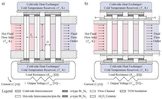
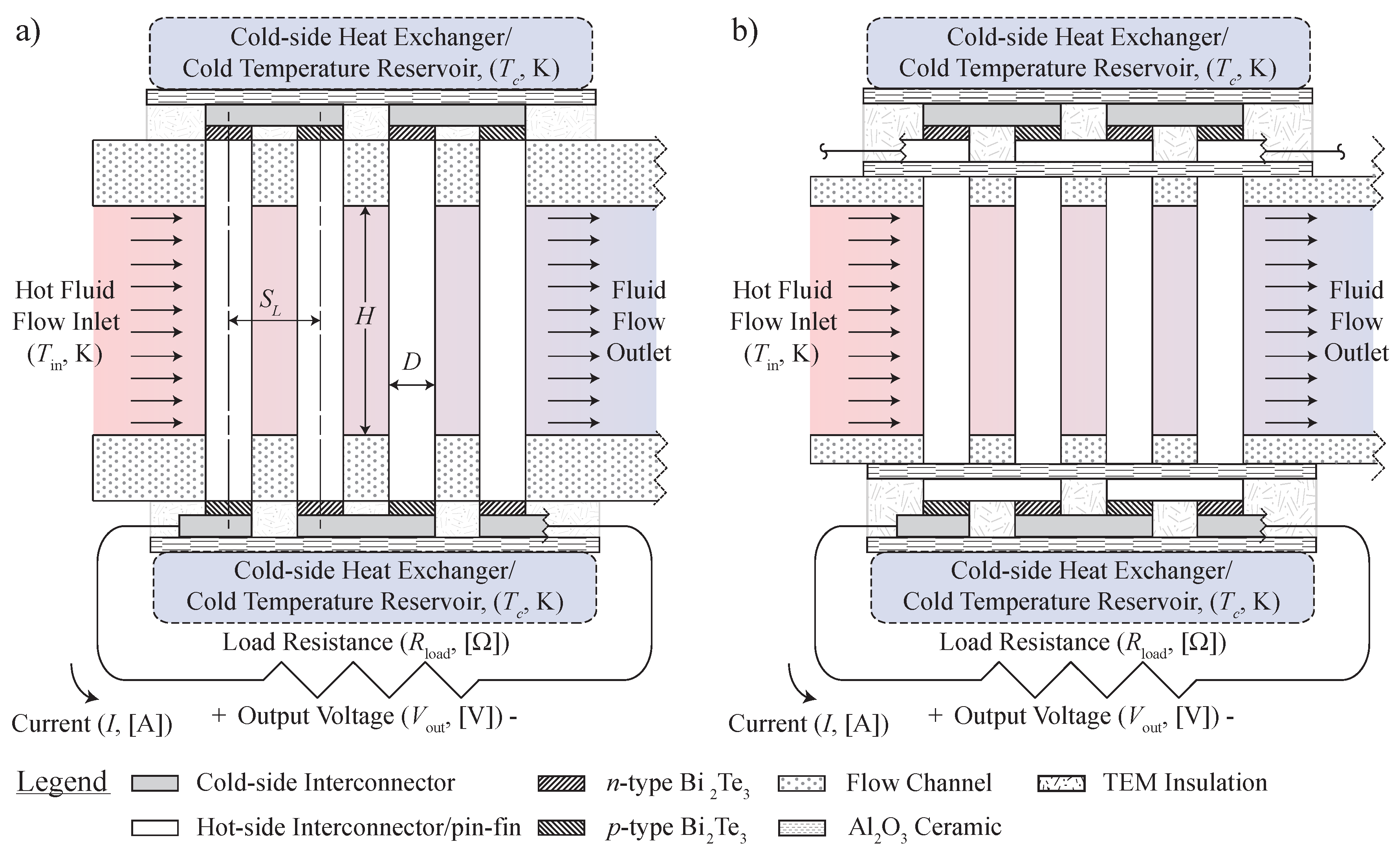
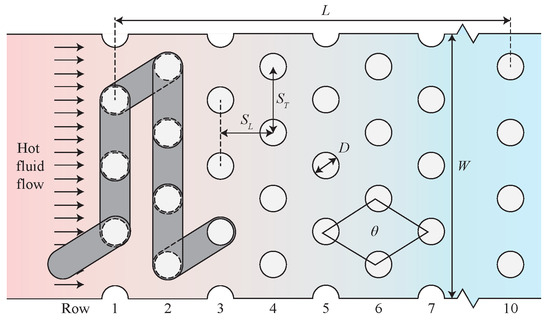
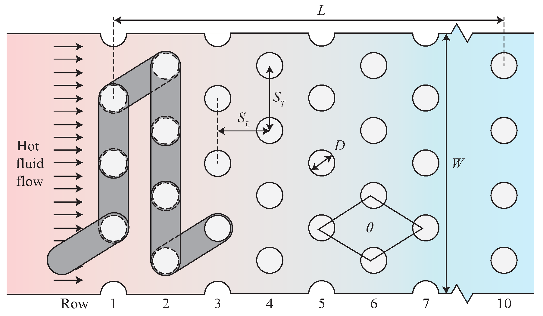
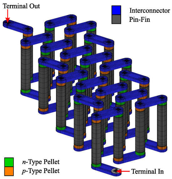
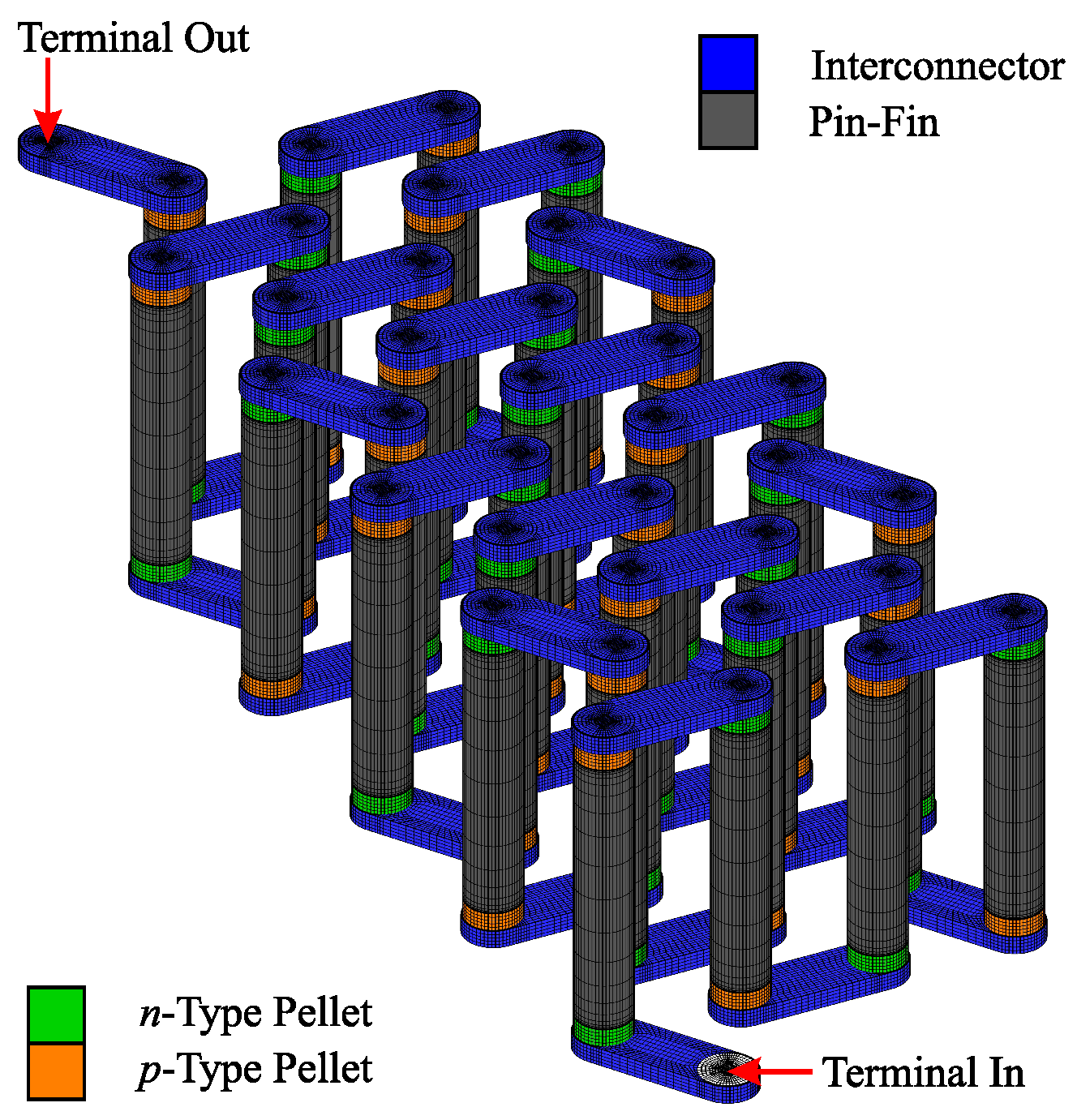
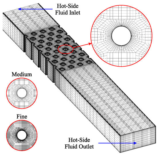
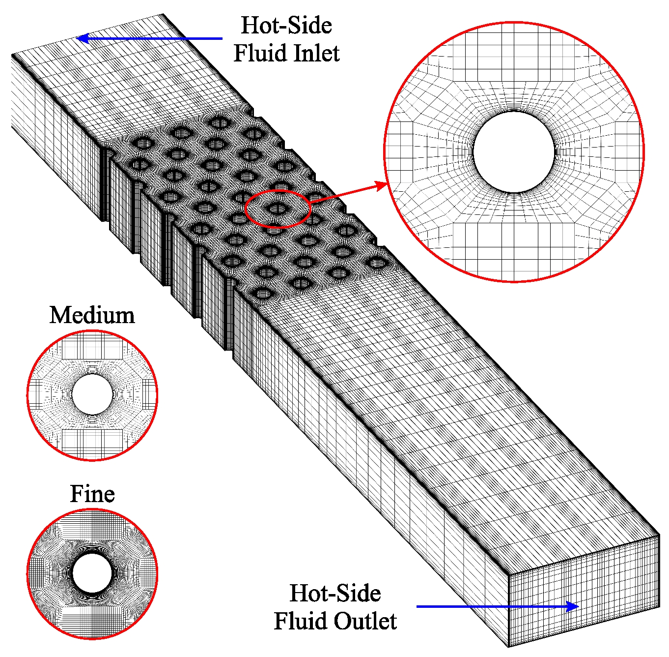
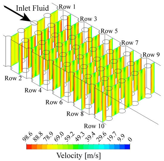
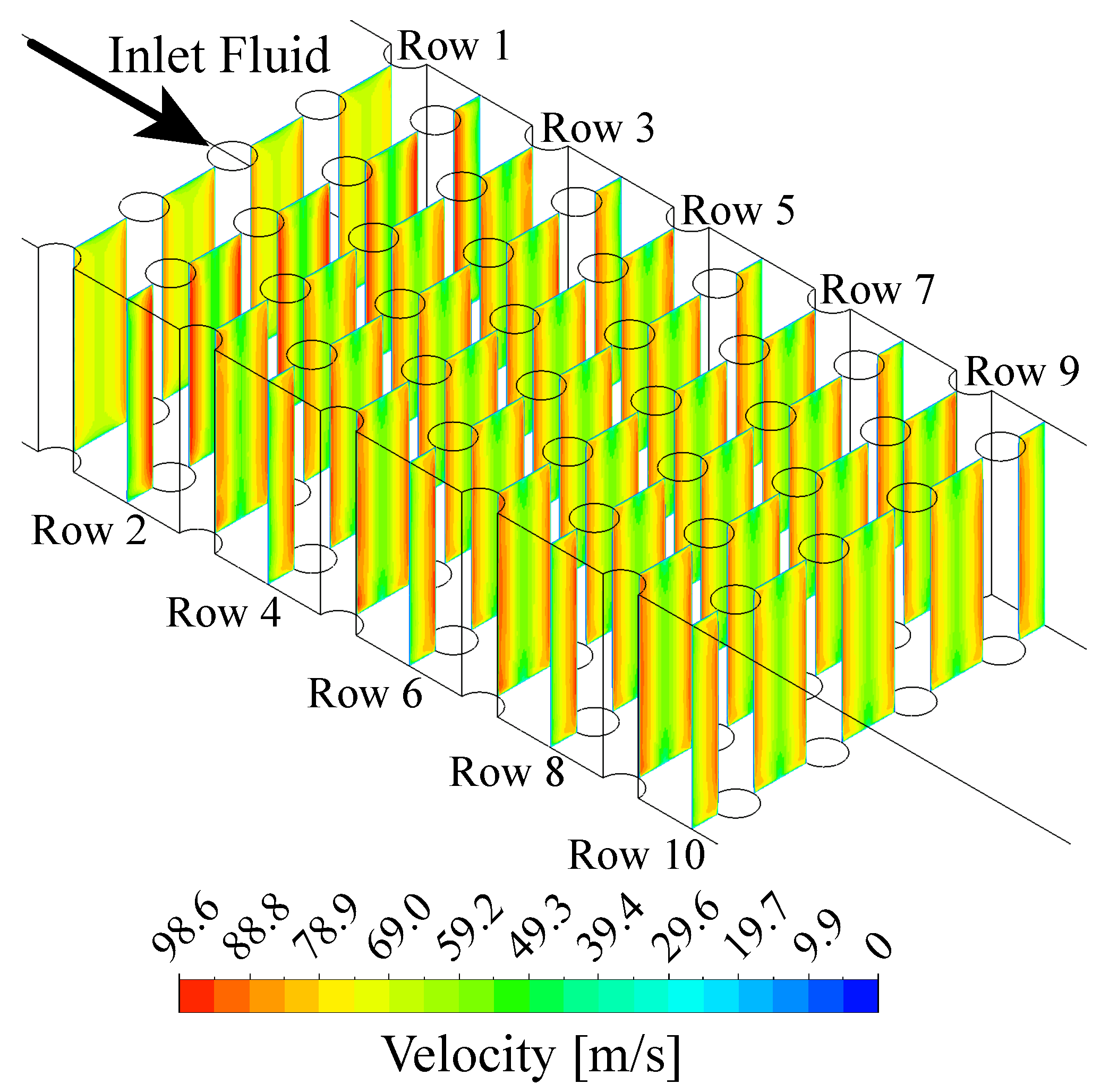
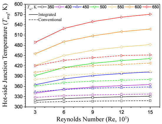
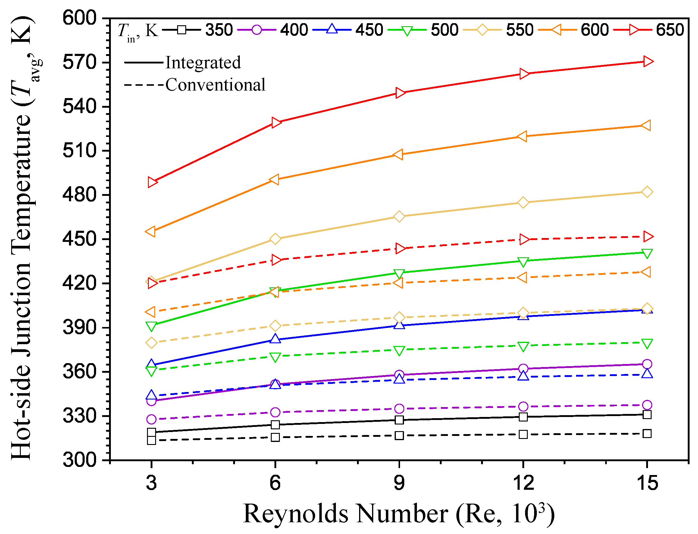
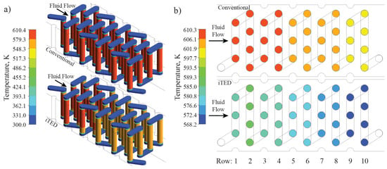
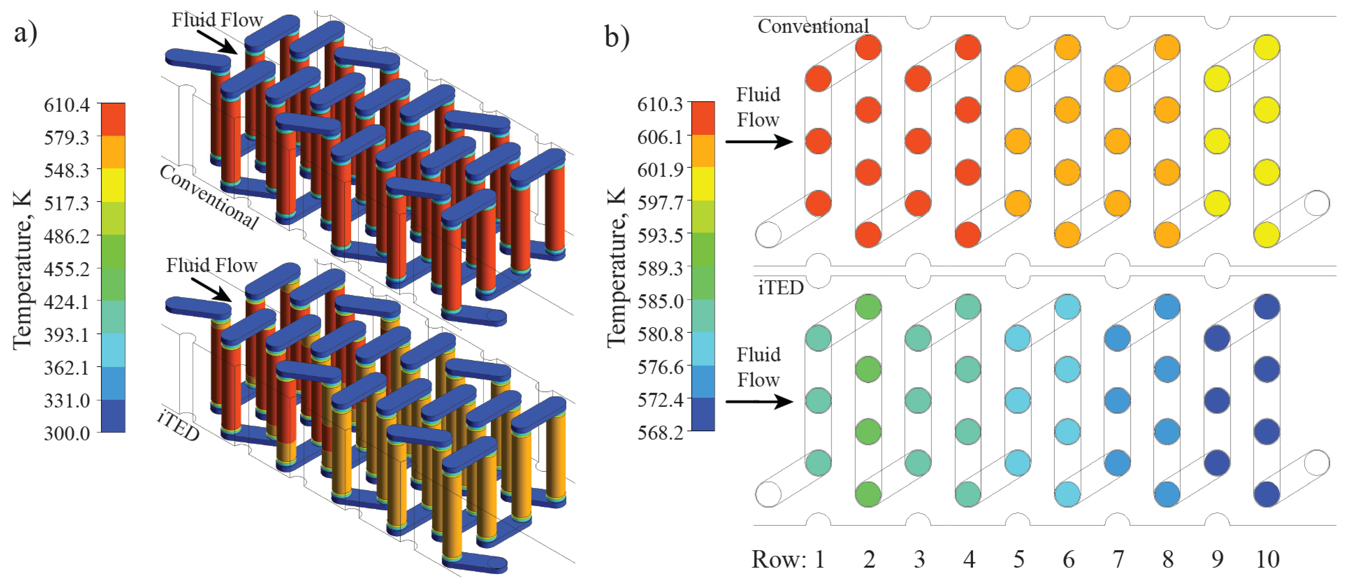
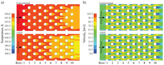
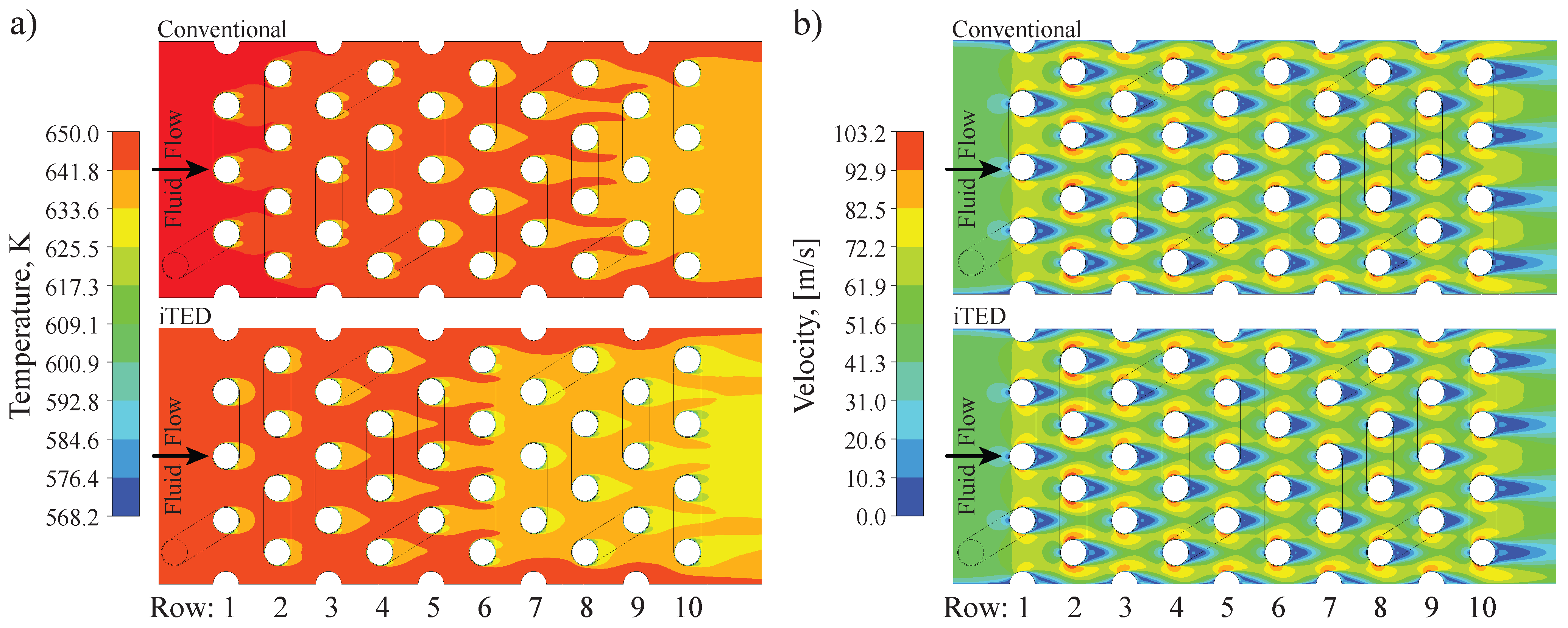
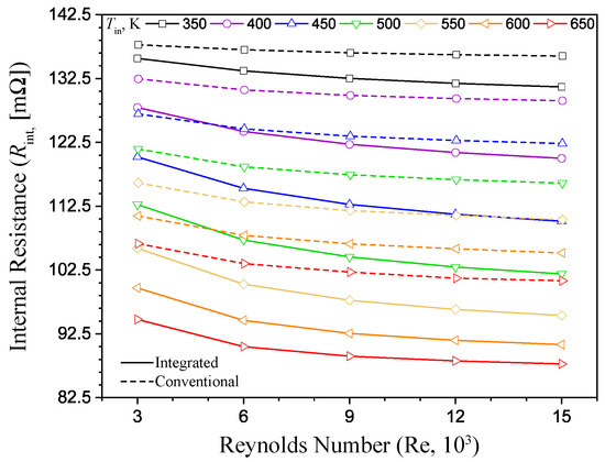
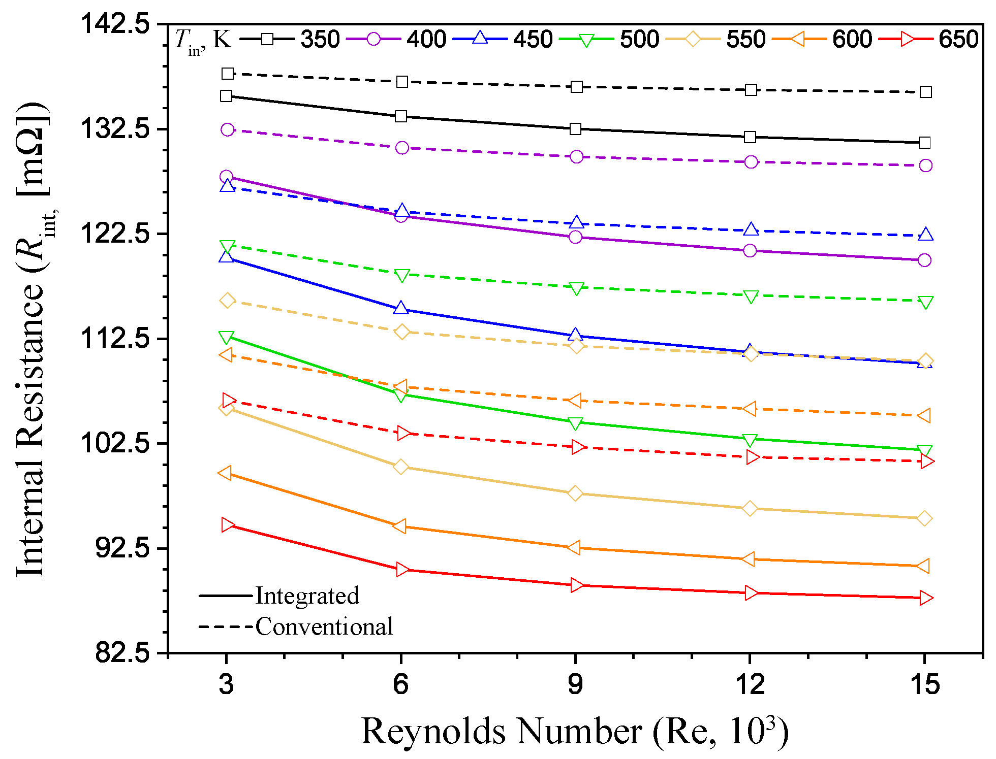
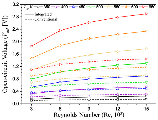
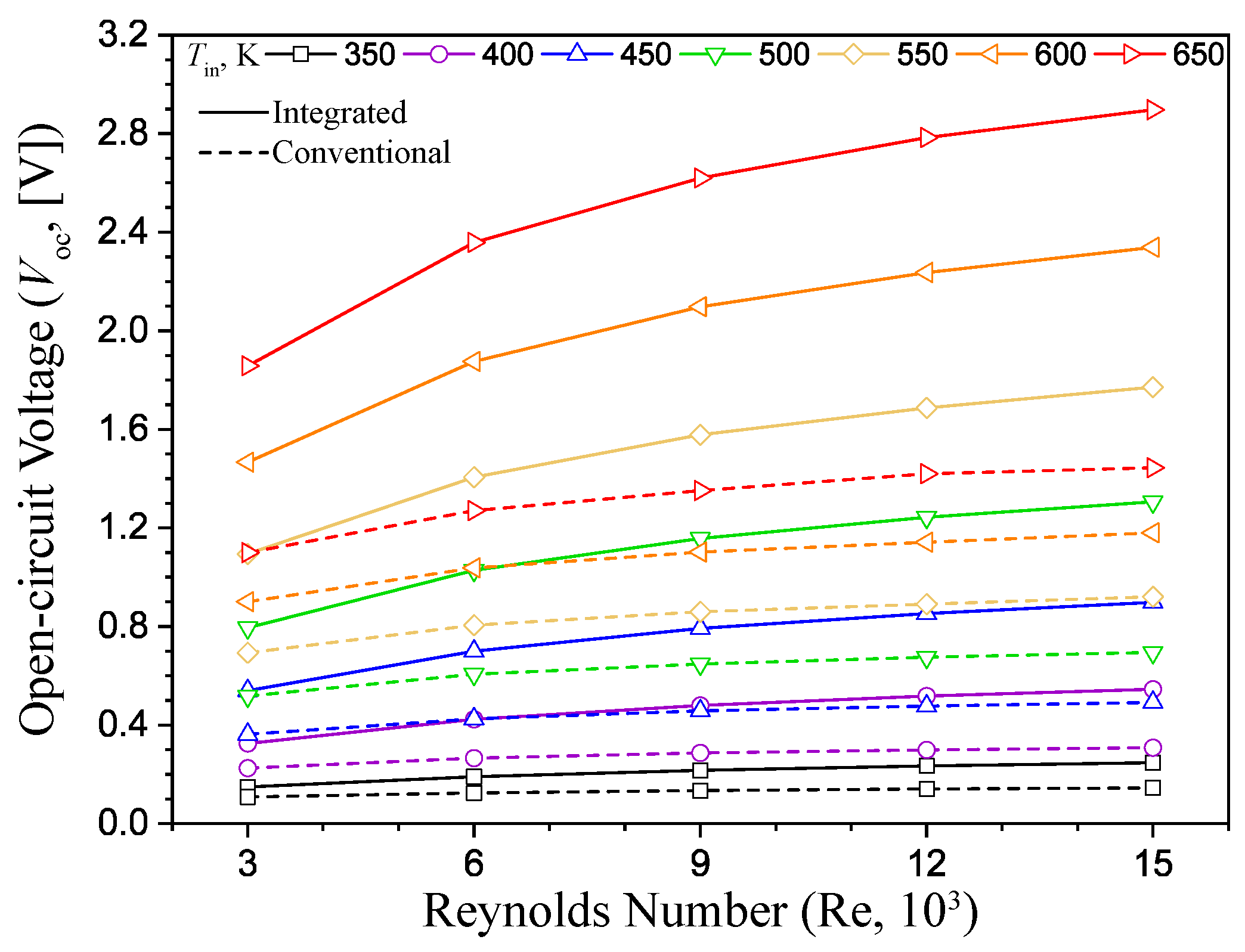
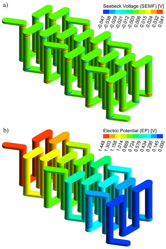
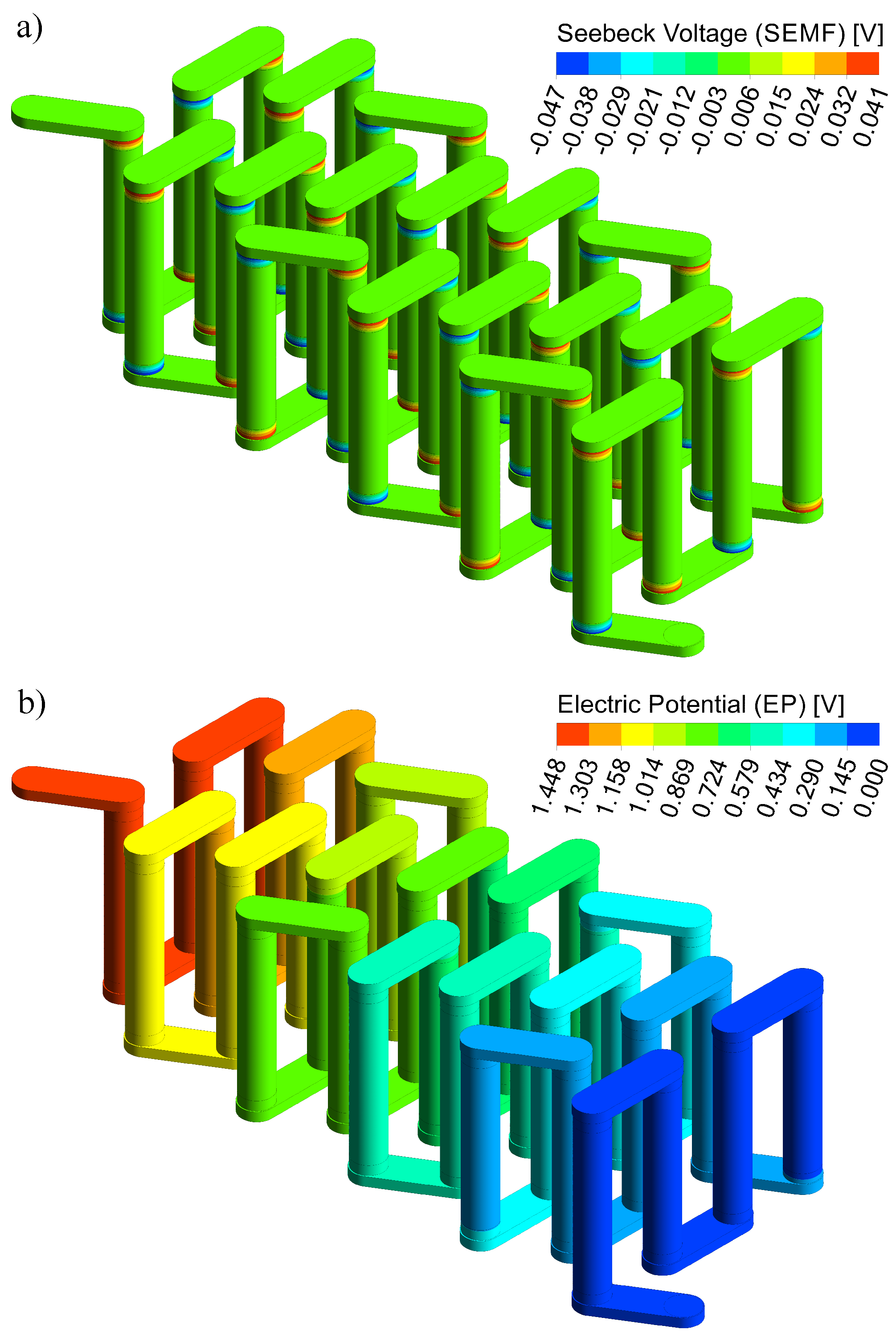
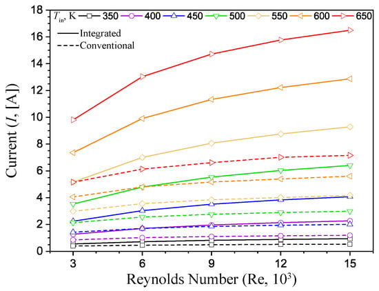
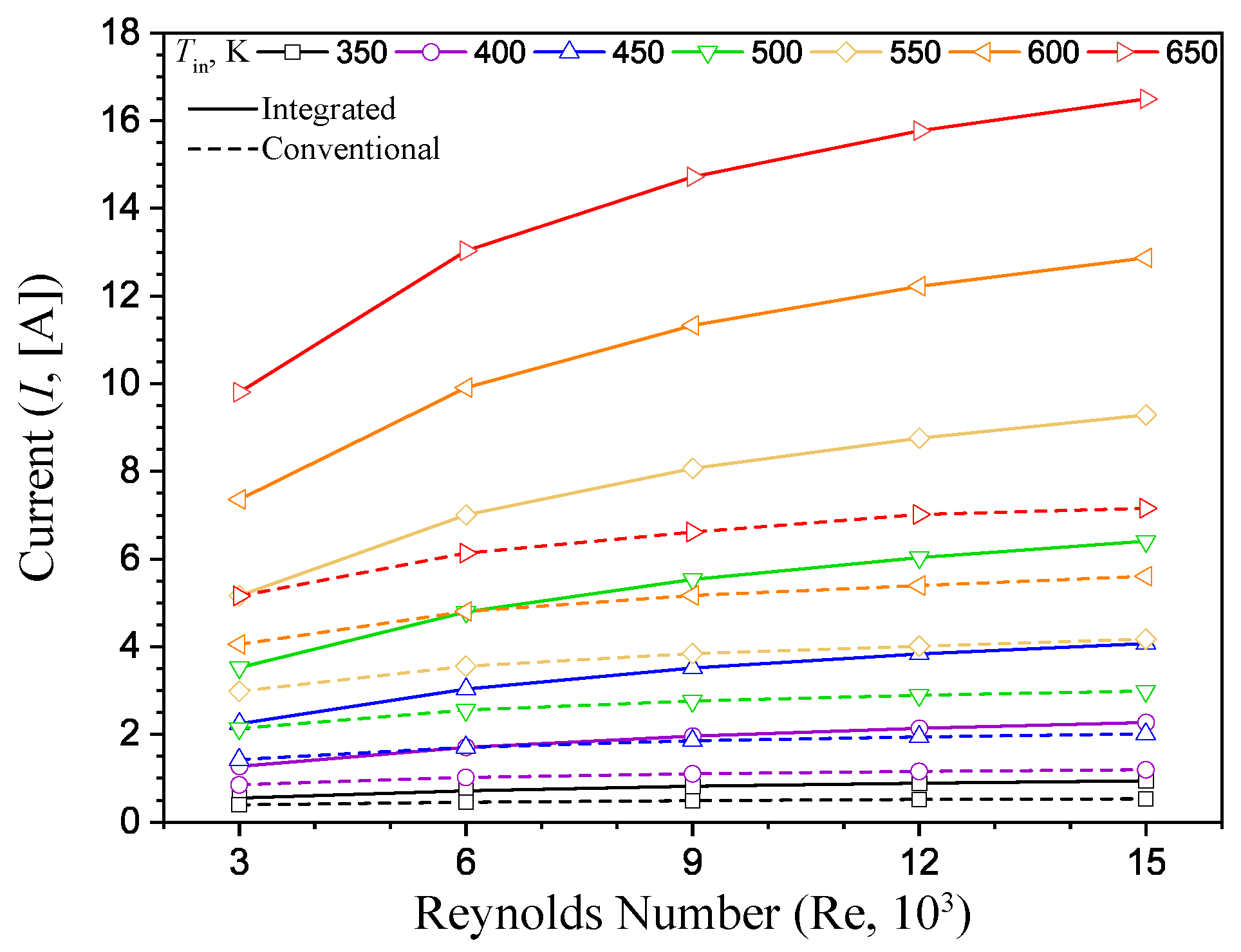
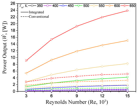
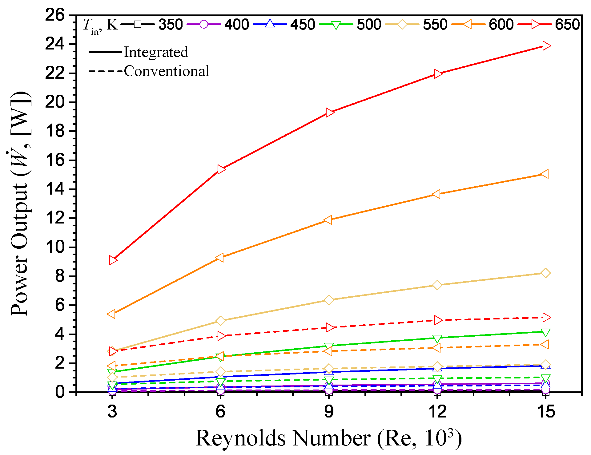
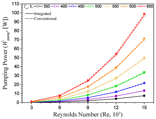
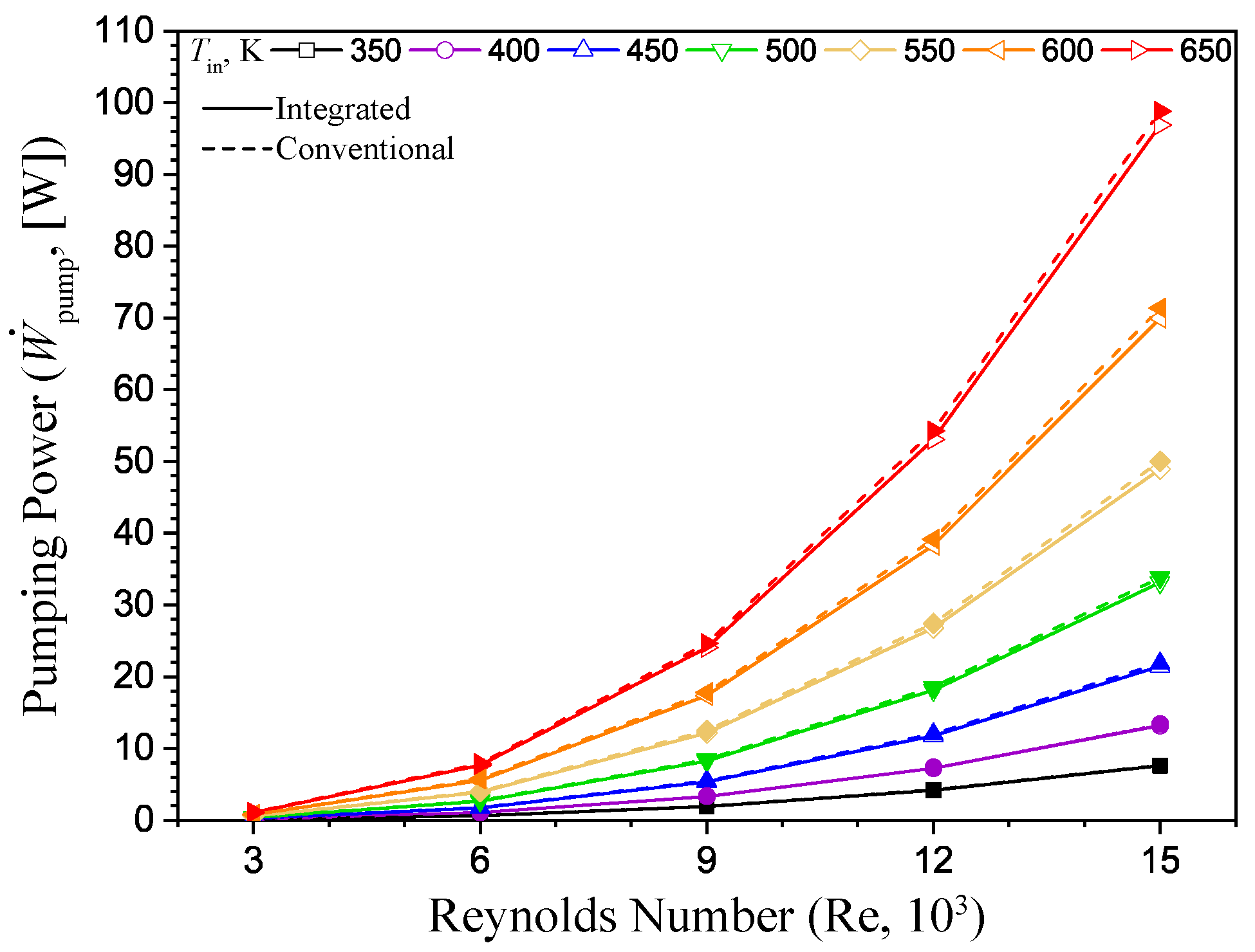
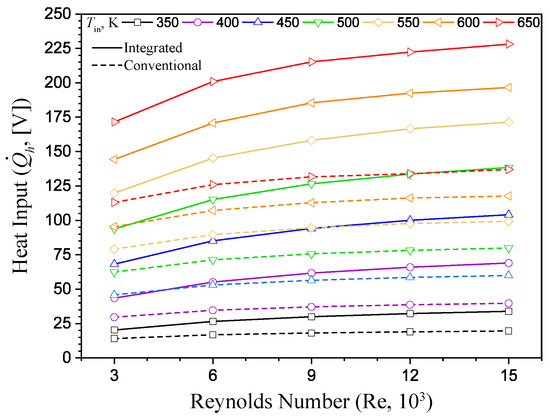
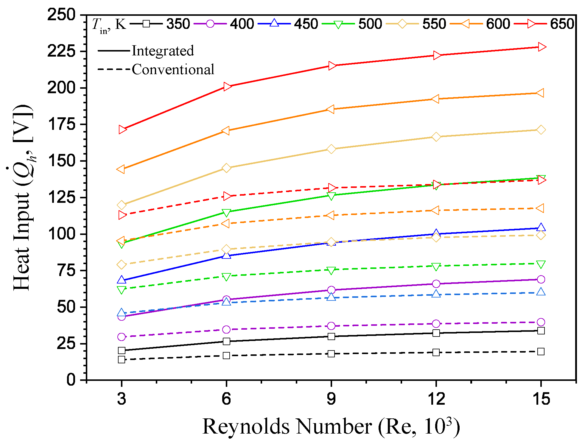
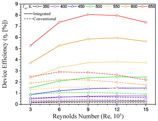
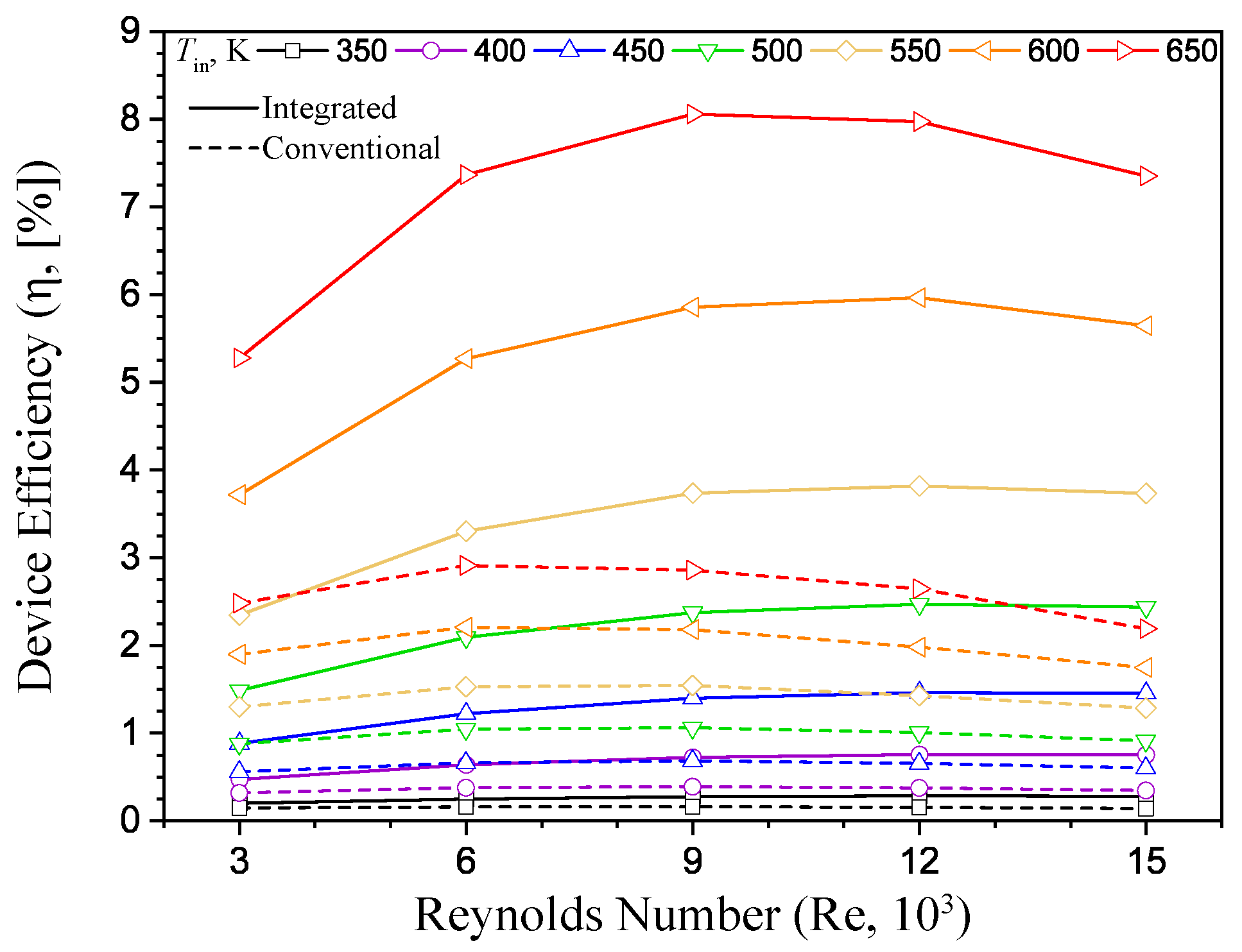
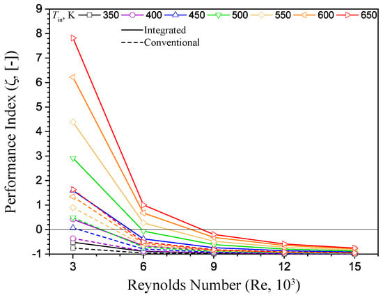
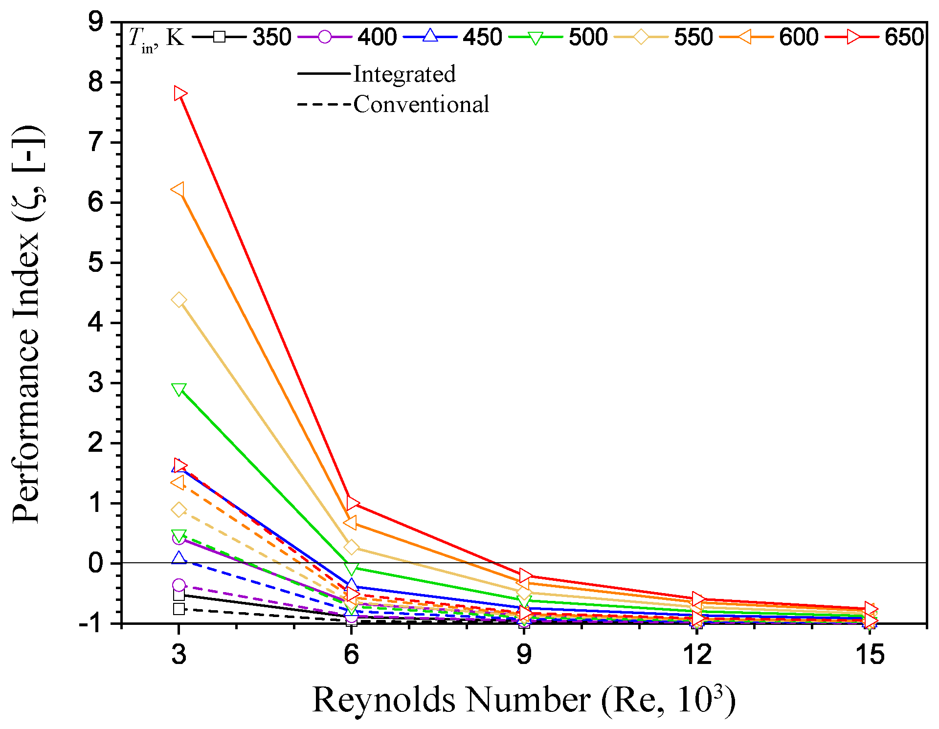
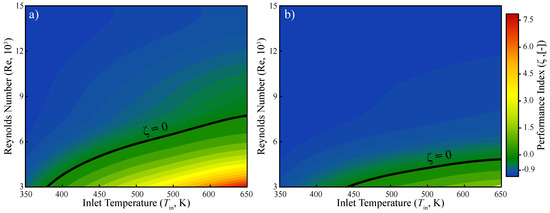
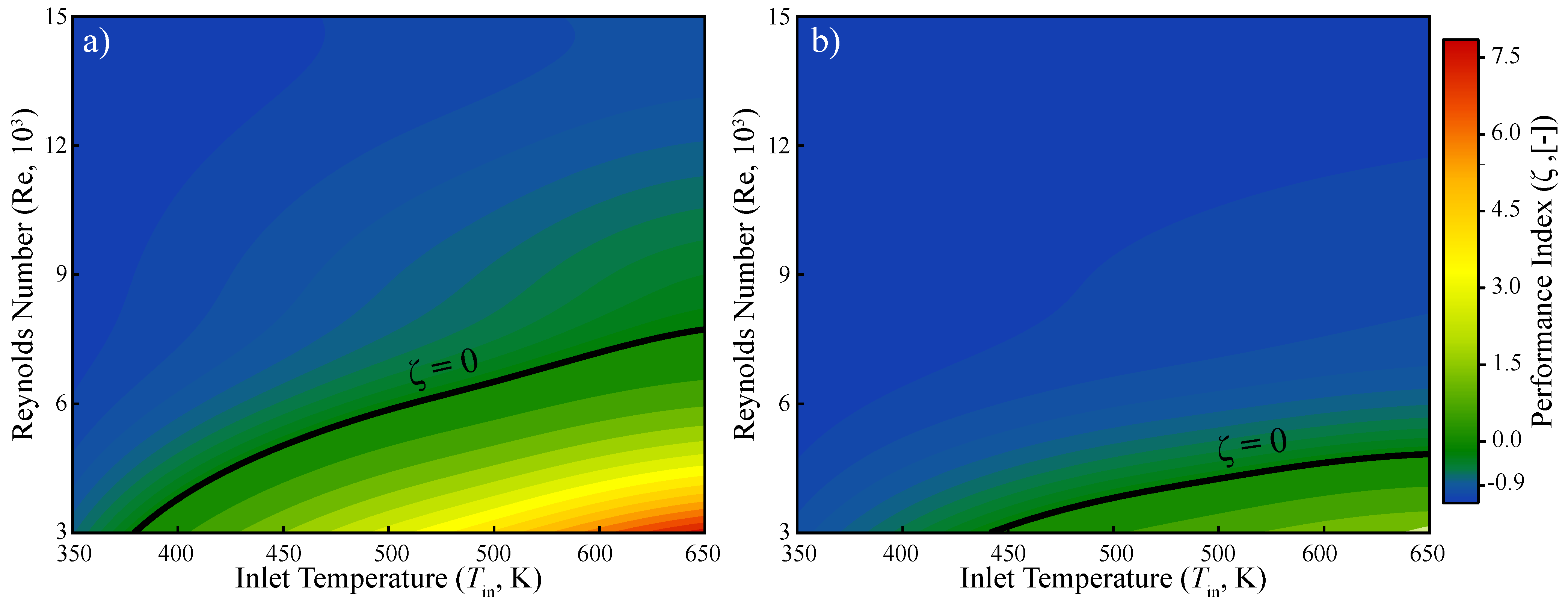
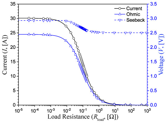
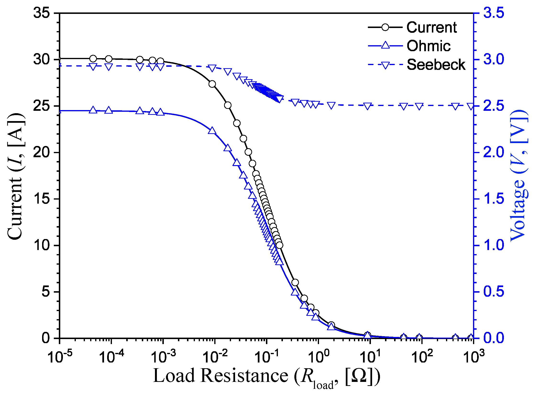
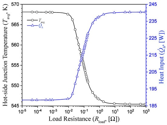
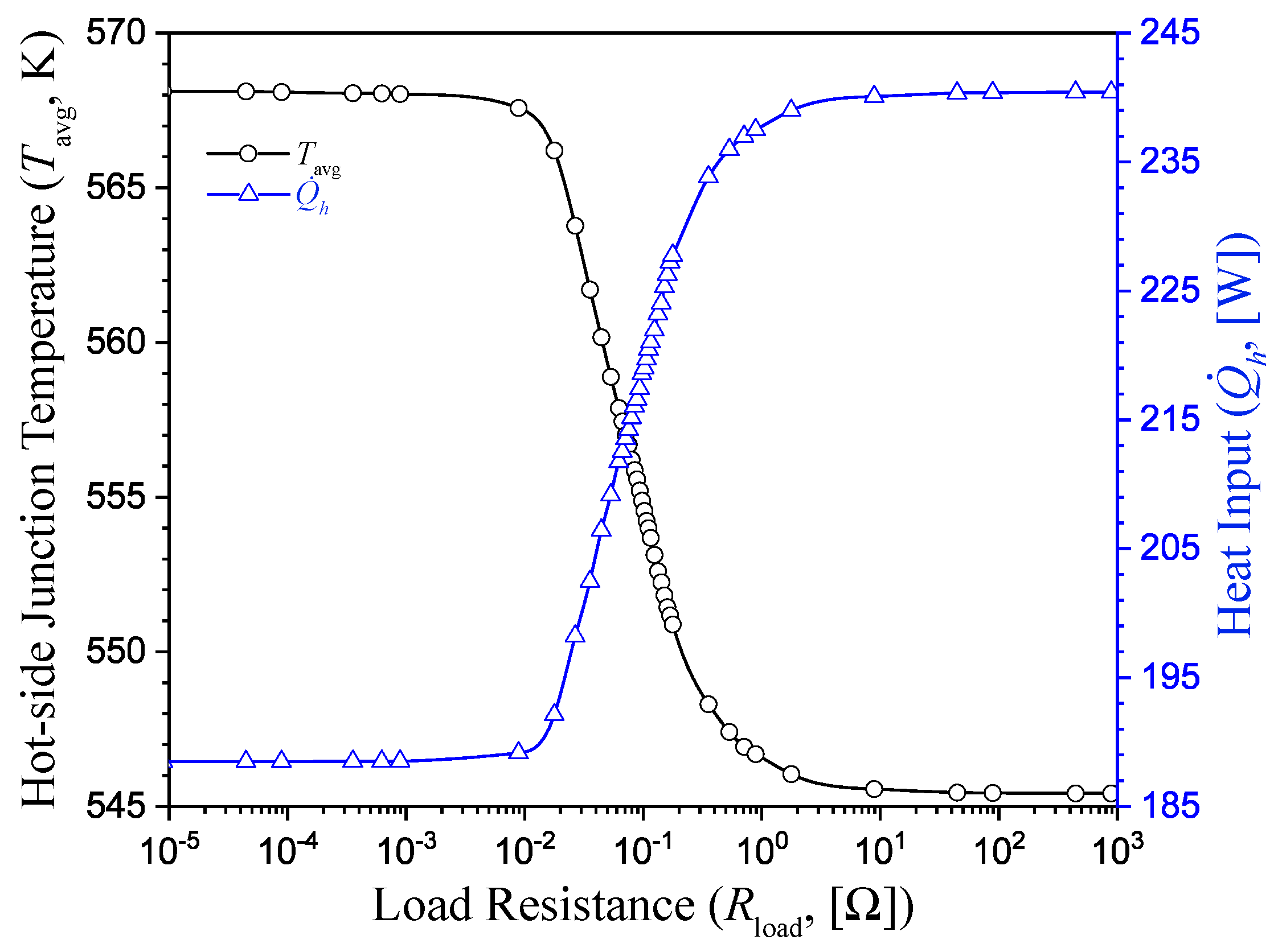
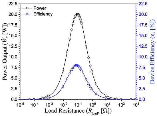
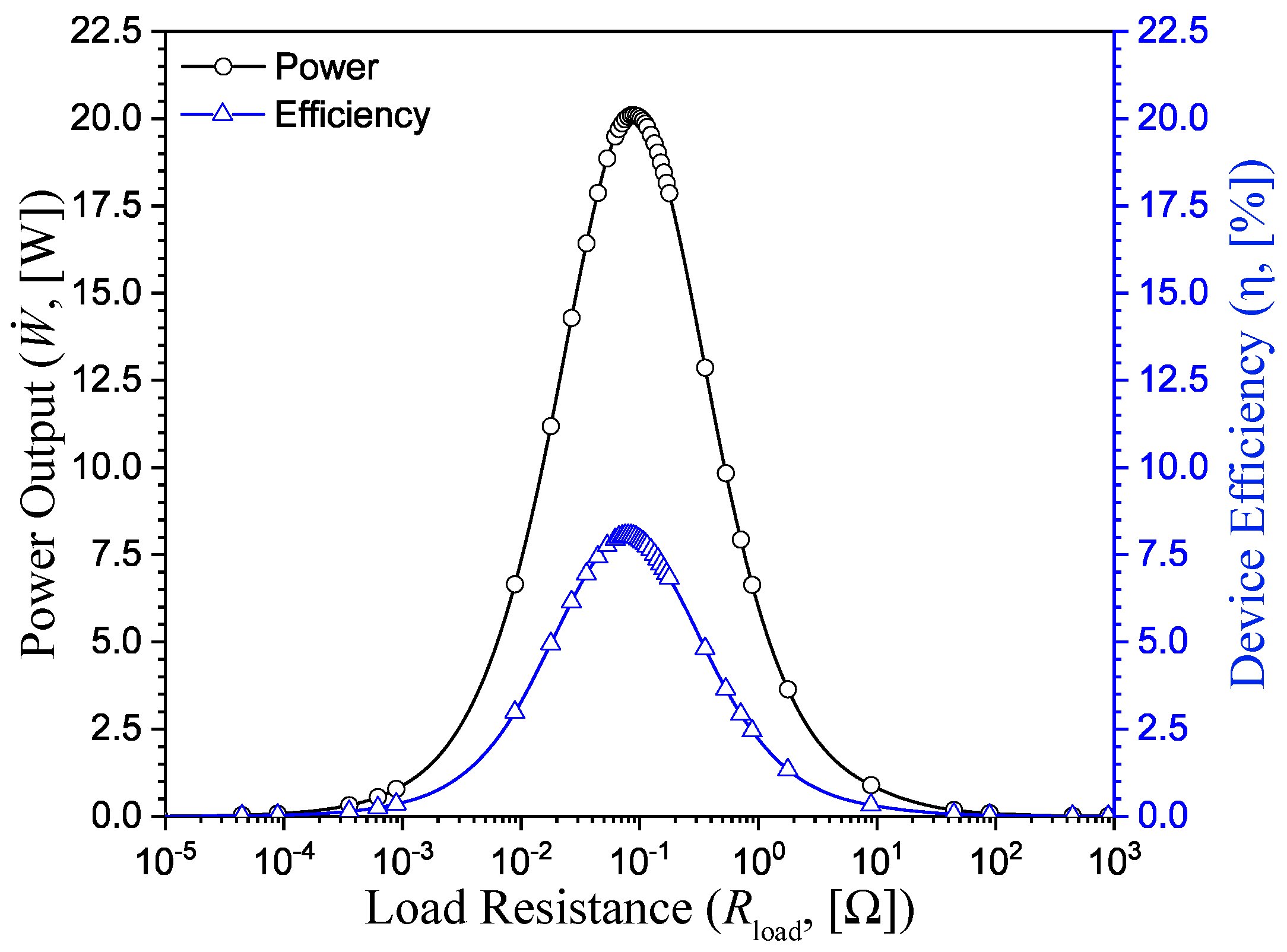
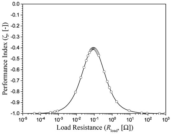
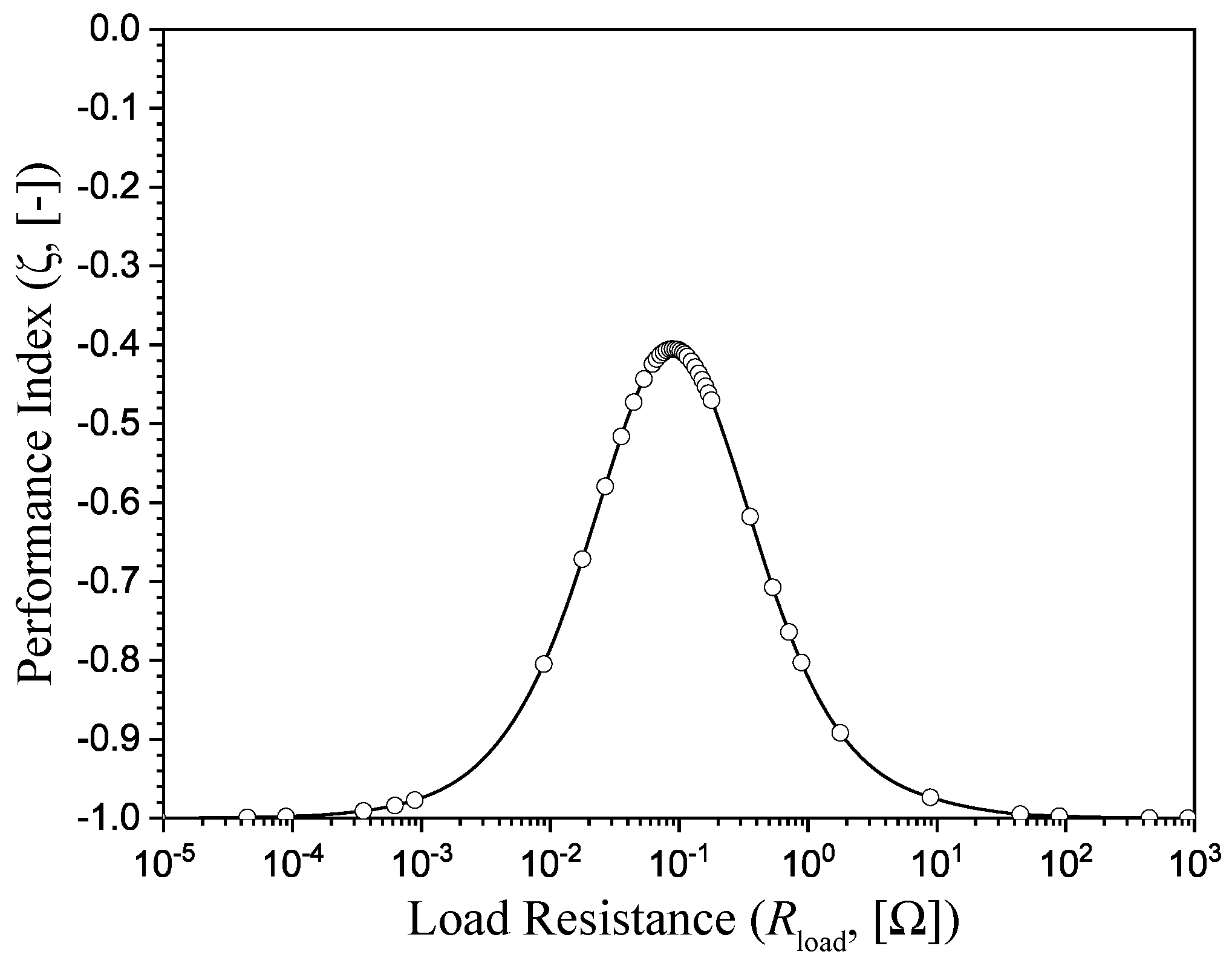

Disclaimer/Publisher’s Note: The statements, opinions and data contained in all publications are solely those of the individual author(s) and contributor(s) and not of MDPI and/or the editor(s). MDPI and/or the editor(s) disclaim responsibility for any injury to people or property resulting from any ideas, methods, instructions or products referred to in the content. |
© 2026 by the authors. Licensee MDPI, Basel, Switzerland. This article is an open access article distributed under the terms and conditions of the Creative Commons Attribution (CC BY) license.