


Abstract
Addressing the long-standing ambiguity in the design of plugging agent dosage for high-water-cut reservoirs—constrained by factors such as insufficient understanding of channeling pathways—this study leverages seepage mechanics theory and well test interpretation data. By investigating the synergistic mechanism between reservoir heterogeneity and plugging agent dosage, we clarified the synergistic control mechanism of the “dual resistance zones” between injection and production wells, and proposed a synergistic target framework: “reservoir heterogeneity—pressure and pressure gradient distribution—profile control to reconstruct the displacement system—dosage of particle and gel plugging agents.” On this basis, the determination criterion for the reasonable profile control radius was provided by systematically analyzing the relationship between the reasonable profile control radius and the development radius of advantage channel. We established dosage calculation models for plugging agents: the equivalent volume method (for particles) and the modified volume method (for gels), and developed a matching relationship between particle size (for particle plugging agents) and fracture aperture. Ultimately, a multi-dimensional synergistic design method for reasonable plugging agent dosage was proposed. Field application and subsequent follow-up evaluation studies have demonstrated that the plugging agent dosage designed by this method for target wells is 0.21~3.53 t/well for particles and 93.51~2399 m3/well for gels. After the implementation of profile control and water plugging measures, the pressure rise was reasonable, and the injection proceeded smoothly. The consistency between well test interpretation results and construction performance reached over 90%, achieving remarkable water control and oil stabilization effects. The research results provide technical support for water control and oil stabilization in high-water-cut reservoirs, and can improve the feasibility of profile control and water plugging design schemes for similar reservoirs by more than 30%.
1. Introduction
During the development of high-water-cut reservoirs, the development of advantage channel results in prominent problems of injected water channeling and ineffective circulation [1,2,3]. There are more than 1700 wells with severe “short-cycle” problems in Jilin Oilfield. Affected by factors such as reservoir complexity and insufficient understanding of channeling pathways, the effect of profile control and water plugging is severely restricted. As a core design parameter, the plugging agent dosage has long been plagued by design ambiguity due to the difficulty in identifying advantage channel and other factors. Existing plugging agent dosage design methods can be categorized into three types: profile control radius method, fuzzy method, and numerical simulation method [4,5,6,7,8,9,10,11,12]. In recent years, preferential pathway identification technology based on pressure gradient analysis has gradually emerged, greatly improving the accuracy of formation preferential pathway identification [13,14,15]. However, all these methods have obvious defects: the profile control radius method suffers from large effect deviations due to the constraints of reservoir complexity; the fuzzy method has strong subjective empiricism and a narrow scope of application; although the numerical simulation method has high accuracy, it relies on model fitting and has a long cycle. More critically, existing studies generally handle the profile control radius and the development radius of advantage channel in isolation, neglecting their synergistic mechanism and failing to establish a multi-parameter coupled design model, which constitutes a core gap in current research. These shortcomings highlight the necessity of constructing a multi-parameter coupled design model. There is an urgent need to establish a reasonable plugging agent dosage design method that balances scientificity and practicality to improve the feasibility of the scheme and the effect of water control and oil stabilization.
To address the above research gaps, this study is based on the multi-dimensional synergistic design idea of seepage mechanics theory and well test interpretation data. By investigating the synergistic action law between reservoir heterogeneity and plugging agent dosage, we reveal the synergistic mechanism between reservoir heterogeneity and plugging agent dosage, and clarify the “dual resistance zones” control target between injection and production wells; establish the dynamic coupling relationship between the profile control radius and the development radius of advantage channel, and propose an accurate method for determining the profile control radius; aiming at the characteristic differences between particle and gel plugging agents, construct dosage calculation models of the equivalent volume method (for particles) and the modified volume method (for gels) respectively, establish the matching relationship between plugging agent particle size and fracture aperture, obtain the particle size screening range of profile control particles, and finally form a multi-parameter synergistic reasonable plugging agent dosage design method. Its effectiveness is verified through field application, providing technical support for water control and oil stabilization in high-water-cut reservoirs.
The overall process is as follows: First, multi-dimensional basic parameters are obtained through well test interpretation, geological survey, and dynamic monitoring; second, calculate the reasonable profile control radius and the development radius of advantage channel respectively, and determine the final profile control radius according to the dynamic coupling criterion; then select the corresponding calculation model according to the type of plugging agent to solve the dosage; finally, output the final design scheme through the verification of the matching between particle size and fracture aperture, and the economic and technical checks, so as to ensure the scientificity and feasibility of the scheme.
2. Synergistic Interaction Between Formation Heterogeneity and Plugging Agent Dosage
Reasonable plugging agent dosage is a key research indicator for the design of profile control and water plugging schemes. It not only exerts a decisive impact on the effective plugging of high-permeability layers or water channeling advantage channels but also helps avoid reservoir damage and cost waste caused by excessive injection. As a comprehensive research indicator affected by multiple factors—including geological parameters, plugging agent properties, and dynamic displacement characteristics-it is challenging to develop a theoretical calculation formula with both universality and accuracy. Among the three commonly used design methods for plugging agent dosage: the profile control radius method is constrained by factors such as reservoir complexity and insufficient understanding of channeling pathways, resulting in poor practical performance or significant discrepancies from predicted results; the fuzzy method is typically characterized by strong subjective empiricism, leading to obvious limitations in its application scope and operating conditions; while the numerical simulation method offers the highest prediction accuracy, it is highly dependent on model fitting precision and entails a long research cycle. Therefore, despite the availability of various design methods, significant ambiguity has persisted in plugging agent dosage design for many years.
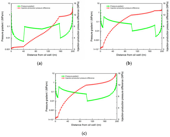
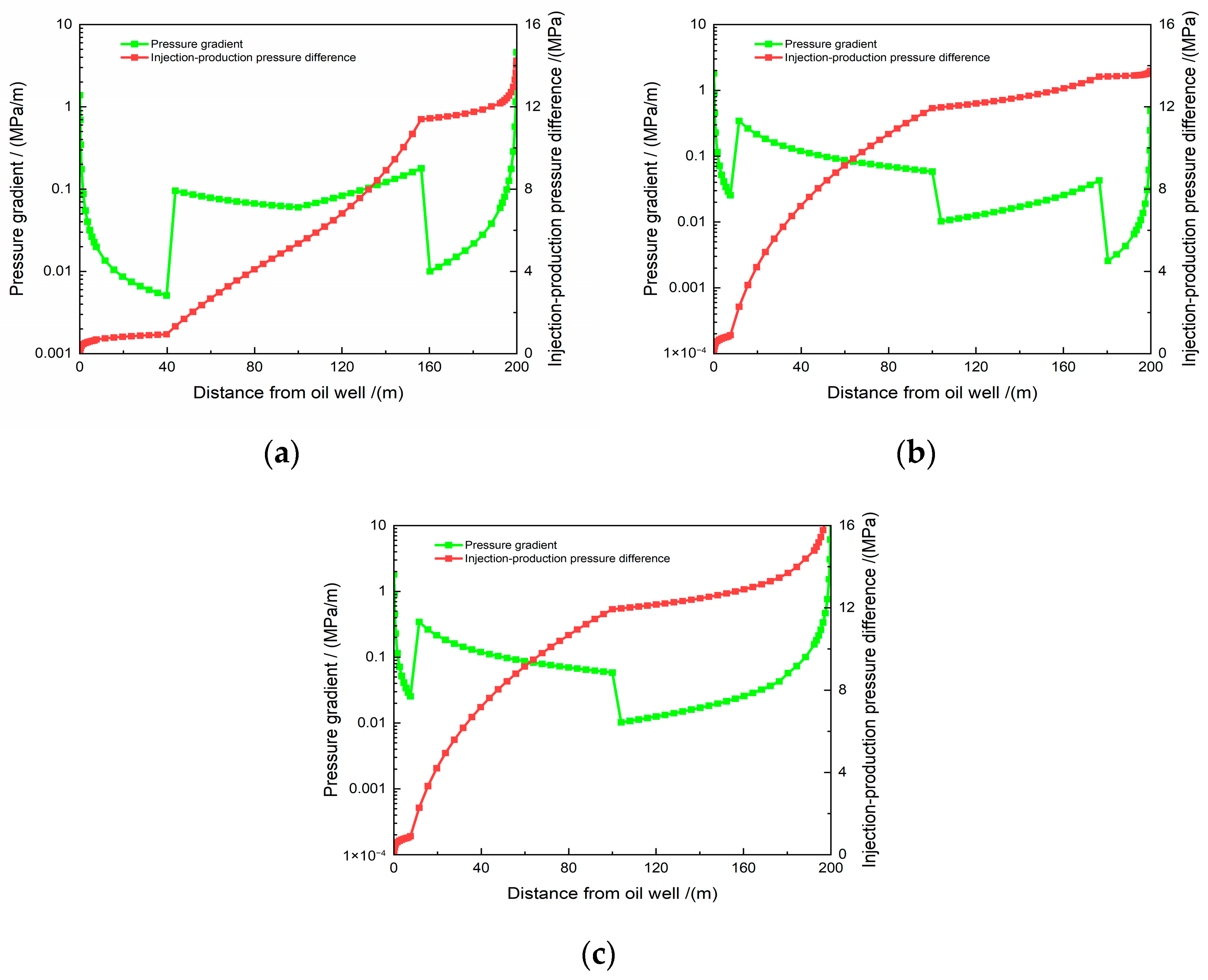
To establish a scientific and efficient design method for reasonable plugging agent dosage, relevant analytical studies were conducted based on seepage mechanics theory and well test interpretation results, starting from the synergistic mechanism between reservoir heterogeneity and plugging agent dosage. Taking a typical profile control well group in a high-water-cut heterogeneous reservoir of Jilin Oilfield as a case study, the variation law of inter-well seepage conditions before and after profile control was analyzed, as illustrated in Figure 1.
Figure 1.
The distribution diagrams of inter-well pressure and pressure gradient in a typical well group before and after profile control: (a) Initial water injection; (b) Before profile control; (c) After profile control.
As illustrated in Figure 1, during the initial water injection phase (Figure 1a), the near-wellbore resistance zone of the injection well is prominent, and the inter-well seepage resistance is also substantial, with the region between injection and production wells governed by dual resistance zones. At this stage, the pressure drop funnel around the near-wellbore is distinct, serving as the core foundation for effective profile sweep. Prior to profile control (Figure 1b), the near-wellbore resistance zone of the injection well is negligible, while the inter-well seepage resistance remains substantial, with the injection-production inter-well region controlled by a single resistance zone. At this point, the near-wellbore pressure drop funnel is indistinct, which constitutes the fundamental cause of inefficient profile sweep. Following profile control (Figure 1c), the near-wellbore resistance zone of the injection well is prominent, and the inter-well seepage resistance is also substantial, with the injection-production inter-well region governed by dual resistance zones. At this stage, the near-wellbore pressure drop funnel is reconstructed, acting as the key driver for the restoration of effective profile sweep.
To summarize, based on well test interpretation results, the pressure and pressure gradient distributions of the seepage field between injection and production wells can be quantified, and two primary resistance zones between wells are elucidated. Among them, the near-wellbore seepage resistance zone is governed by the pressure drop funnel mechanism, whereas the inter-well seepage resistance zone is controlled by the relatively low permeability mechanism. Furthermore, the core of the synergistic effect between reservoir heterogeneity and plugging agent dosage lies in the fundamental contradiction of heterogeneous reservoirs: the excessive permeability difference between high-permeability advantage channel and low-permeability matrix, which induces preferential fluid channeling. In contrast, the key role of plugging agent dosage is to establish effective resistance in both the near-wellbore and inter-well zones through precise injection. Targeting the heterogeneous characteristics of developed high-permeability advantage channel, the scope of advantage channel is determined via well test interpretation, and the corresponding profile control radius and plugging agent dosage are matched. This enables the plugging agent to fill high-permeability pathways in the near-wellbore zone to form an artificial resistance zone, and seal the extended segments of advantage channel in the inter-well zone to establish a natural-artificial composite resistance zone. When the plugging agent dosage is precisely matched with the degree of reservoir heterogeneity, the dual resistance zones can balance the pressure distribution between injection and production wells, forcing fluids to divert from high-permeability pathways to the low-permeability matrix, thereby achieving uniform reservoir sweep efficiency and ultimately fulfilling the goal of water control and oil stabilization. Conversely, insufficient plugging agent dosage fails to fully establish the dual resistance zones, leaving preferential channeling in high-permeability pathways. Excessive dosage, on the other hand, excessively increases seepage resistance, leading to an abnormal rise in injection pressure and even damage to the low-permeability matrix. Therefore, the synergistic mechanism between reservoir heterogeneity and plugging agent dosage can be summarized as: mitigating the inter-well permeability distribution discrepancy, reconstructing the near-wellbore pressure drop funnel, and achieving dual resistance zone control between injection and production wells.
In the high water-cut heterogeneous reservoir, the threshold of resistance coefficient is defined as 1.8–2.5 for the near-well seepage resistance zone. The value is determined based on the statistics of multiple sets of indoor core experiments and field test wells in Jilin Oilfield. It shows that the near-well resistance can effectively realize the reconstruction of pressure drop funnel and avoid the rapid breakthrough of plugging agent under this threshold. The depth range of the near-well pressure drop funnel corresponding to the effective ‘double resistance zone‘ is clearly 3.5–8.0 m, which is derived from the well test interpretation data of the target wells (M2, M3, M4). For the inter-well seepage resistance zone, the reasonable range of pressure drop ratio is determined to be 0.35–0.55. In this interval, the inter-well seepage resistance is moderate, which can not only avoid the difficulty of injection, but also effectively control the dominant channel. It is clear that the reasonable interval of inter-well pressure gradient corresponding to the effective ‘double resistance zone‘ is 0.012–0.025 MPa/m. This interval is verified by the dynamic monitoring data of field profile control construction, which can ensure the collaborative optimization of near-well pressure drop funnel reconstruction and inter-well permeability difference regulation.
On this basis, the synergistic objectives between reservoir heterogeneity and plugging agent dosage are proposed, encompassing two key aspects: First, guided by the pressure and pressure gradient distribution characteristics in the initial water injection stage, alleviate the profile discrepancy between injection and production wells. Second, with appropriate plugging agents and reasonable dosage as controls, and profile control wells as endpoints, achieve the synergy among reservoir heterogeneity, pressure, and pressure gradient distribution, profile control-based displacement system reconstruction, and particle/gel plugging agent dosage, thereby reconstructing the seepage field centered on profile control wells.
3. Methodology for Designing the Rational Dosage of Plugging Agents
3.1. Method for Determining the Profile Control Radius
The profile control radius is one of the key parameters for the design of reasonable plugging agent dosage. Two types of profile control radii are commonly used in practice: the reasonable profile control radius and the development radius of advantage channel. Although both are parameters describing the scope of high-permeability zones, they differ in physical meaning, and thus, their calculation methods are also distinct. However, existing studies often overlook their differences and equate the two, using only one of the indicators as the profile control radius for reasonable plugging agent dosage design. This results in the actual profile control effect in oilfields failing to meet the expected performance of the scheme, and may even inflict certain damage to the reservoir.
To address the above issue, while considering the different physical meanings and calculation methods of the reasonable profile control radius and the development radius of advantage channel, a method for determining the profile control radius with high accuracy and simplicity in operation is proposed through scientific analysis and systematic summary of field practices. Specifically, this method is based on quantitatively interpreted parameters from single-well well tests, balancing the plugging of near-wellbore advantage channel and the scope of the reasonable profile control radius: when the development scope of near-wellbore advantage channel falls within the range of the reasonable profile control radius, the former shall be adopted as the reference; when the development scope of near-wellbore advantage channel exceeds the range of the reasonable profile control radius, the latter shall be used as the reference.
The mathematical expression for the profile control radius of a single well derived using this method is as follows:
where: R: single-well profile control radius, m; Rch: development radius of advantage channel, m; Ropt: reasonable profile control radius, m.
3.1.1. Optimal Profile Control Radius
The optimal profile control radius is defined as the effective scope within which profile control and plugging agents can efficiently seal high-permeability zones (e.g., fractures, large pore throats) following formation injection. Subject to the dual constraints of plugging efficiency and development economics, the optimal profile control radius must be determined via engineering optimization. Three primary methods are widely adopted for its determination: numerical simulation, theoretical calculation, and field monitoring inversion. Specifically, the numerical simulation method employs reservoir simulation software to predict the sweep range of profile control and plugging agents; the theoretical calculation method computes the sweep efficiency based on seepage mechanics theory or oilfield empirical formulas; the field monitoring inversion method infers the actual diffusion range of the agents using on-site dynamic monitoring data. The applicable conditions for each method are provided in detail in Table 1.
Table 1.
Applicability of the method for determining the reasonable profile control radius.
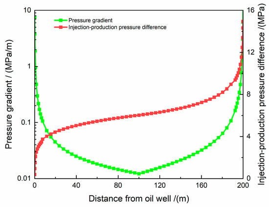
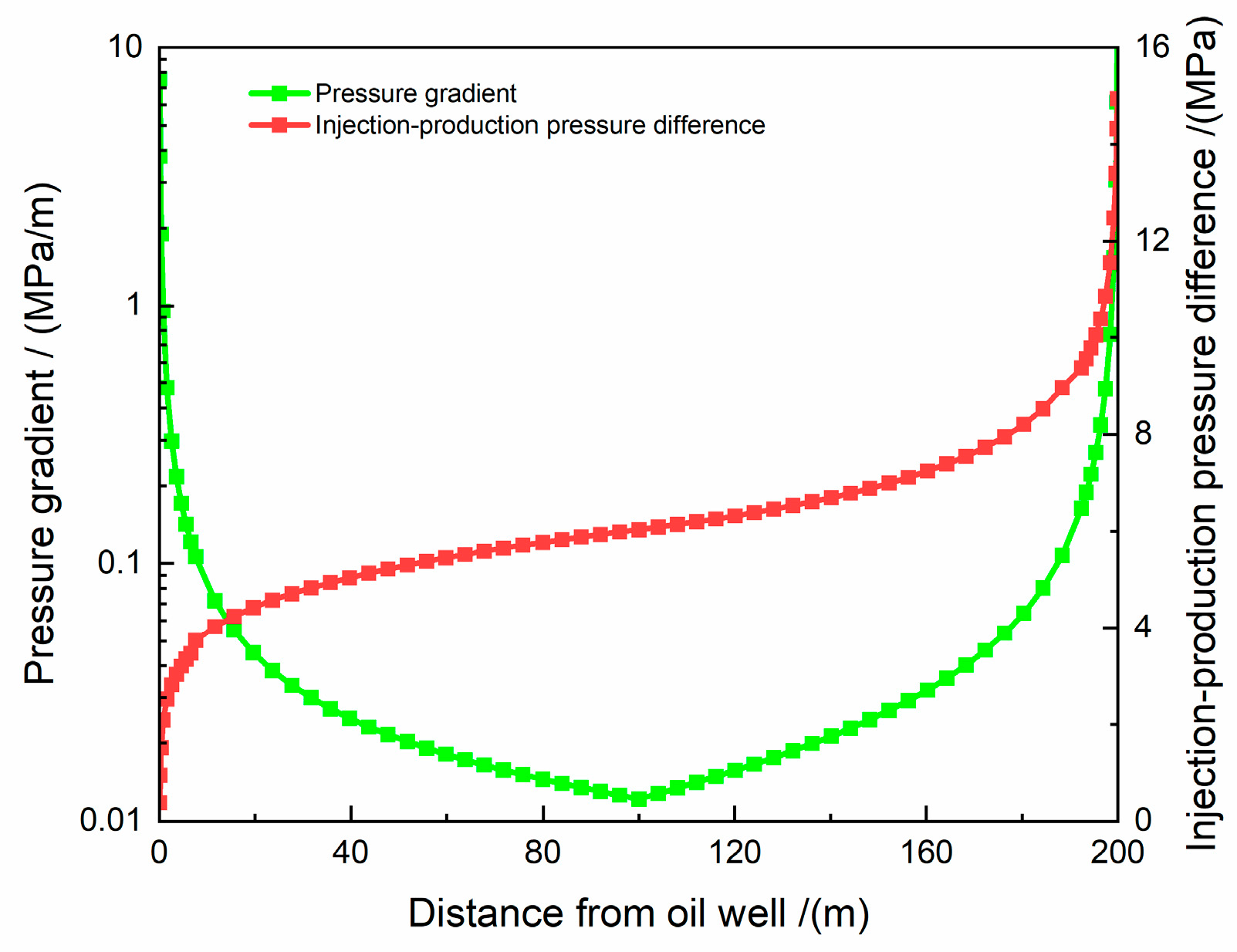
As illustrated in Table 1, the field monitoring inversion method offers broad applicability with minimal constraints from reservoir conditions. It is characterized by low estimation cost, high efficiency, and the ability to promptly reflect the dynamic changes of the profile control radius, making it the preferred approach for determining the optimal profile control radius. Among various field monitoring datasets, injection-production pressure difference and pressure gradient data can be utilized to define the range of the optimal profile control radius. Specifically, the inflection point of the inter-well pressure gradient curve is adopted as the reference point for the optimal profile control radius, as depicted in Figure 2.
Figure 2.
Distribution of inter-well pressure and pressure gradient in the case of a single channel.
Two rationales support the selection of this reference point: first, injection-production pressure difference and pressure gradient data are readily available without requiring additional testing, enabling a simple and efficient determination process; second, the inflection point of the inter-well pressure gradient curve indicates an abrupt change in the characteristics of fluid flow within the formation. Specifically, the abrupt change is typically associated with the following factors: (1) Transition boundary between high-permeability strips and low-permeability matrix: profile control and plugging agents preferentially penetrate high-permeability strips or advantage channel; upon sealing the edge of the high-permeability strip, the fluid is forced to divert to low-permeability regions, causing a distinct change in pressure gradient and the formation of an inflection point. (2) Position of the profile control and plugging agent front: the inflection point may correspond to the effective sealing front of the agents within the formation, namely, the boundary of the agents’ effective action range.
Thus, adopting the inflection point of the inter-well pressure gradient curve as the reference point for the optimal profile control radius offers a clear physical significance and high reliability. From an engineering standpoint, the inflection point of the inter-well pressure gradient curve signifies the completion of high-permeability zone plugging and the initiation of fluid diversion, and its position can be approximately considered as the effective action radius of the plugging agent (optimal profile control radius). Real-time monitoring of pressure gradient changes enables the assessment of whether the plugging agent has achieved the designed sealing range and provides guidance for the dynamic adjustment of agent dosage.
3.1.2. Preferential Pathway Development Radius
The preferential pathway development radius is defined as the lateral scope of localized high-permeability regions. These regions form when injected water preferentially and rapidly invades along higher-permeability paths, driven by long-term waterflood development or reservoir heterogeneity (e.g., high-permeability strips, large pore throats, fractures). To date, six primary methods are widely employed to determine the preferential pathway development radius, encompassing technical approaches including dynamic data analysis, theoretical model derivation, and numerical simulation. The calculation principles and applicability of each method are provided in detail in Table 2.
Table 2.
Principles and applicability of the method for determining the development radius of advantage channel.
As shown in Table 2, although existing methods for determining the development radius of advantage channel exhibit distinct advantages and disadvantages, they generally fail to achieve synergy among computational speed, calculation accuracy, and method applicability. Therefore, a novel method for determining the development radius of advantage channel is proposed. Guided by seepage mechanics theory and based on well test interpretation results, this method was developed through the analysis and synthesis of development radius data of advantage channel from numerous practical profile control well groups in high-water-cut heterogeneous sandstone reservoirs. It enables the rapid and convenient determination of the development radius of advantage channel when using profile control particles or gels as plugging agents. The development scope of advantage channel is essentially the extension boundary of the region with the minimum seepage resistance to injected water. The inner zone radius obtained from well test interpretation (scope of the near-wellbore high-permeability zone) is a core parameter characterizing this resistance boundary. The multiple relationship between the development radius of advantage channel and the inner zone radius must satisfy the “balance condition between near-wellbore plugging resistance and inter-well seepage resistance” to avoid residual channeling due to an excessively small plugging scope or abnormal injection pressure caused by an excessively large scope.
To verify the rationality of this multiple relationship, two aspects of research were conducted: First, laboratory physical simulation experiments were performed. Heterogeneous core displacement devices with different inner zone radii (laboratory core models scaled to correspond to 5~50 m) were constructed. Particle and gel plugging agents were injected separately, and changes in seepage resistance during different injection stages were monitored to determine the quantitative correlation between the extended scope of effectively plugged advantage channel and the inner zone radius. Second, statistical analysis of field data was carried out. Well test interpretation data, plugging agent injection data, and dynamic monitoring results from 82 profile control wells in 5 high-water-cut blocks (including Jilin Oilfield and Daqing Oilfield) were collected. Through linear fitting and significance testing, the optimal multiple relationships between the development radius of advantage channel and the inner zone radius for particle and gel plugging agents were determined. Both experimental and statistical results indicate that, due to their larger particle size and higher plugging strength, particle plugging agents require coverage of a wider preferential pathway scope to achieve stable plugging, with the development radius of advantage channel being 2.5 times the inner zone radius. In contrast, gel plugging agents, with their inherent fluidity and sweep capacity, can achieve deep plugging without an excessively large coverage scope, and their corresponding development radius of advantage channel is 2.0 times the inner zone radius. The goodness of fit (R2) for these multiple relationships is all greater than 0.85, meeting engineering accuracy requirements.
When the plugging agent is a profile control particle, the method for determining the development radius of advantage channel is as follows:
When the profile control and plugging agent are gel-based, the approach for determining the preferential pathway development radius is as follows:
In the equation: R denotes the radius of development for advantage channel, m; p stands for profile—modifying particles; g represents profile—modifying gel; r is the inner—zone radius derived from well—test interpretation, m.
3.2. Approach for Quantifying Plugging Agent Dosage
3.2.1. Single-Well Dosage of Profile Control Particles
The dosage design of particle-based profile control agents employs the equivalent volume method [16,17], whereby injected particles fill special pathways (e.g., fractures) within the profile control radius. The particles exhibit minimal downhole swelling behavior, and fracture porosity is constrained within a relatively defined range. Considering the functional mechanism of profile control particles and the complexity of reservoir fracture systems, the fracture porosity is assigned a value of 0.0003. The design formula for single-well profile control particle dosage is thus:
In the equation, Wp denotes the amount of profile—modifying particles, m3; Rp denotes the radius of the profile—modifying particles, m; h is the thickness of the reservoir, m.
By accounting for the optimal value of the preferential pathway development radius and substituting Equation (2) into Equation (4), the design formula for the dosage of particle-based profile control agents is derived as:
The single-well profile control particle dosage design method is founded on a universal basis, thus enabling its applicability to diverse reservoir types.
3.2.2. Single-Well Dosage of Profile Control Gels
The dosage design of gel-based profile control agents employs the volume method [18,19,20,21,22,23], which means that the injected profile control gel can fill the scope of the designed profile control radius. Considering the complexity of underground seepage of plugging agents, the inaccessible pore volume is not additionally accounted for, while profile control gels with special properties are considered separately. while gels with specialized properties are evaluated independently [24,25,26,27]. However, profile control gels exhibit a significant apparent chromatographic effect during underground seepage, which reduces the effective gelation range [28,29,30]. Therefore, based on previous research, a safety factor of 1.5 is adopted. This safety factor is determined based on systematic laboratory core flow experiments and field validation data. Through fitting analysis of experimental data, when the safety factor is set to 1.5, the effective gelation range of the gel in more than 90% of the experimental groups can cover the designed profile control radius without causing an abnormal increase in injection pressure due to excessive injection. When the safety factor exceeds 1.8, although the plugging effect is stable, the increased plugging agent dosage leads to a rise in treatment cost by more than 15%, resulting in a significant decrease in economic efficiency. Considering both plugging effect and economic efficiency, the optimal safety factor is determined to be 1.5. Supported by the aforementioned experimental and field data, the design formula for the dosage of profile control gels can be derived as follows:
In the formula, Wg represents the dosage of profile—control gel in, m3; Rg is the radius of the profile—control gel, m; Φ is the reservoir porosity; h is the thickness of the reservoir, m.
By accounting for the optimal value of the preferential pathway development radius and substituting Equation (3) into Equation (6), the design formula for the dosage of gel-based profile control agents is derived as:
This single-well profile control gel dosage design method is founded on a universal framework, thus facilitating its applicability to various reservoir types.
It should be pointed out that the insurance coefficient 1.5 proposed in this paper is based on the experimental statistics of the target block and its similar medium-high permeability reservoirs. For extremely low porosity or fractured reservoirs, it is recommended to conduct experimental verification in combination with specific cores and re-fit the optimal value.
3.3. Matching Correlation Between Plugging Agent Particle Size and Fracture Aperture
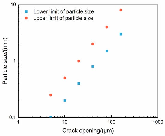
As profile control particles deform during migration through subsurface pathways, a combination of experimental data, field observations, and theoretical analysis is required to establish the optimal matching correlation between the well test-interpreted fracture aperture (b) and the profile control particle size (D).
Using statistical analysis of field data from Jilin Oilfield, a correlation curve describing the matching relationship between profile control particle size and fracture aperture is derived, as illustrated in Figure 3.
Figure 3.
Relationship between particle size and crack aperture.
As shown in Figure 3, two nearly parallel linear correlations exist between profile control particle size and fracture aperture: one defines the upper limit of the particle size, and the other specifies the lower limit.
Consequently, the screening range of profile control particle size, considering the influence of fracture opening matching, is Formula (8):
In the equation, D represents the particle size in millimeters, and b represents the fracture opening in micrometers.
In the present study, the screening of profile control particle size only accounts for the effect of fracture aperture, with the influence of particle concentration not yet incorporated.
4. Field Implementation
4.1. Profile Control Adaptability Assessment for Target Wells
Taking Jilin Oilfield as a case study, this research conducts a reliability tracking assessment of plugging agent dosage design. The optimal plugging agent dosage method proposed herein is applied to 14 target wells across multiple low-permeability and medium-high permeability reservoirs.
First, the 14 target wells are assessed in accordance with the existing classification criteria for profile control adaptability (Table 3), with the results presented in Table 4.
Table 3.
Classification standards for profile control adaptability evaluation.
Table 4.
Evaluation results of profile control adaptability for target wells.
In the table, the water injection pressure 1 is the corresponding pressure when the water injection pipe network pressure is 15 MPa, and the water injection pressure 2 is the corresponding pressure when the water injection pipe network pressure is 10 MPa.
As illustrated in Table 4, among the 14 target wells, 5 exhibit good profile control adaptability, 5 show moderate adaptability, and 4 have poor adaptability. Among the 4 wells with poor adaptability, 3 are no longer suitable for single-well profile control to mitigate profile conflicts and reconstruct the displacement system, primarily due to their large inner zone radius. Profile control and flooding are recommended to reconstruct the inter-well seepage field between injection and production wells.
4.2. Plugging Agent Dosage Optimization for Profile Control Wells
Based on the profile control adaptability evaluation results in Table 4, three wells (M2, M3, and M4) with evaluation results of “good”, “moderate”, and “poor”, respectively, were selected as examples. The reasonable plugging agent dosage for every single well was calculated using the proposed reasonable plugging agent dosage design method in this study. See Table 5 for details of the design parameters and calculation results. The basic geological and well test parameters in the table were all obtained from the completion geological reports of the target wells and the interpretation of single-well steady-state well tests.
Table 5.
Calculation parameters for the dosage of plugging agent for each well.
As shown in Table 5, for parameters such as inner zone permeability, inner zone radius, and fracture aperture obtained from well test interpretation results, the corresponding values are relatively small for the well with good profile control adaptability (M2), while those for the wells with moderate (M3) and poor (M4) adaptability are relatively large. The calculated parameters, including the upper and lower limits of particle size, profile control radius (for particles and gels), and plugging agent dosage (for particles and gels), follow the same trend. In addition, the inner zone radii of these three wells all fall within the reasonable range of the development radius of advantage channel, and the development radius of advantage channel is smaller than the reasonable profile control radius. Therefore, the profile control radius used in the plugging agent dosage design is numerically equal to the inner zone radius. Thus, it can be concluded that the main parameters affecting the plugging agent dosage design results are the inner zone radius and fracture aperture: the former determines the size of the profile control radius, and the latter determines the particle size.
It should be noted that the profile control radius values, such as 10 m and 8 m in the table, are not fixed thresholds but are calculated based on the dynamic coupling criterion proposed in this study (Equation (1)). Taking Well M2 as an example: its inner zone radius obtained from well test interpretation is 4.5 m, the calculated development radius of advantage channel for particle plugging agents is (R is 11.25), and that for gel plugging agents is (R is 9); meanwhile, the reasonable profile control radius of this well is determined to be 12 m via the field monitoring inversion method. Therefore, the final profile control radii are set to 10 m and 8 m, respectively. The relevant values, such as 30 m and 50 m mentioned, are classification thresholds for profile control adaptability evaluation, determined based on statistical analysis of a large amount of field practice data. The 50 m value serves as the ultimate reference for the development radius of advantage channel: if the calculated development radius of advantage channel exceeds 50 m, it indicates that the reservoir channeling pathways are extremely developed, and single-well profile control can no longer achieve effective plugging, requiring the adoption of a well group profile control and flooding method. This threshold is derived from the verification results of the “limit of single plugging scope” in large-scale laboratory physical simulation experiments.
4.3. Field Monitoring and Comparative Analysis
Analysis of on-site construction curves indicates that after implementing profile control and water plugging with the plugging agent dosage designed in this study for Wells M2, M3, and M4, the pressure rise was reasonable and the injection proceeded smoothly—verifying the rationality of the plugging agent dosage design. Meanwhile, the consistency between well test interpretation results, comprehensive dynamic and static analysis, and construction performance exceeds 90%, demonstrating excellent effectiveness and high reliability of the field tracking and comparative analysis. To clarify the practical effect and application value of profile control and water plugging, quantitative statistics were conducted on the production performance data of the three wells 6 months after implementation. Table 6 presents the improvements in key indicators, achieving the water control and oil stabilization objectives of a significant reduction in water cut and a steady increase in oil production. This study provides a pragmatic and feasible technical scheme for the development of high-water-cut reservoirs.
Table 6.
The quantitative table of core production index improvement after profile control of target well.
In the Table 6, the water content 1 is the water content before profile control, the water content 2 is the average water content of 6 months after profile control, the daily oil production is the average daily oil production of 6 months after profile control, the daily oil increase is the daily oil increase after profile control, and the cumulative oil increase is the cumulative oil increase of 6 months after profile control.
As shown in Table 6, the profile control and water plugging measures exhibit a remarkable effect on water control and oil stabilization in high-water-cut reservoirs: after profile control, the water cut of all three wells decreased significantly by 9.1~12.7 percentage points; the daily oil production increased positively, with the cumulative oil increment ranging from 237.0 to 457.5 t, and the oil recovery factor improved by 0.8~1.3%. Among them, Well M2, with good profile control adaptability, achieved the optimal improvement effect—exhibiting the highest water cut reduction and cumulative oil increment. This validates the rationality of the profile control adaptability evaluation criteria proposed in this study and indicates that the method delivers superior application effects for reservoirs with good adaptability. Compared with existing studies, the proposed method ranks among the leading levels in terms of water cut reduction and oil recovery factor improvement. Additionally, it offers higher accuracy in plugging agent dosage design, effectively avoiding cost waste caused by excessive injection. This study provides more valuable theoretical and technical support for the design of plugging agent dosage in high-water-cut reservoirs.
- (I)
- Well M2
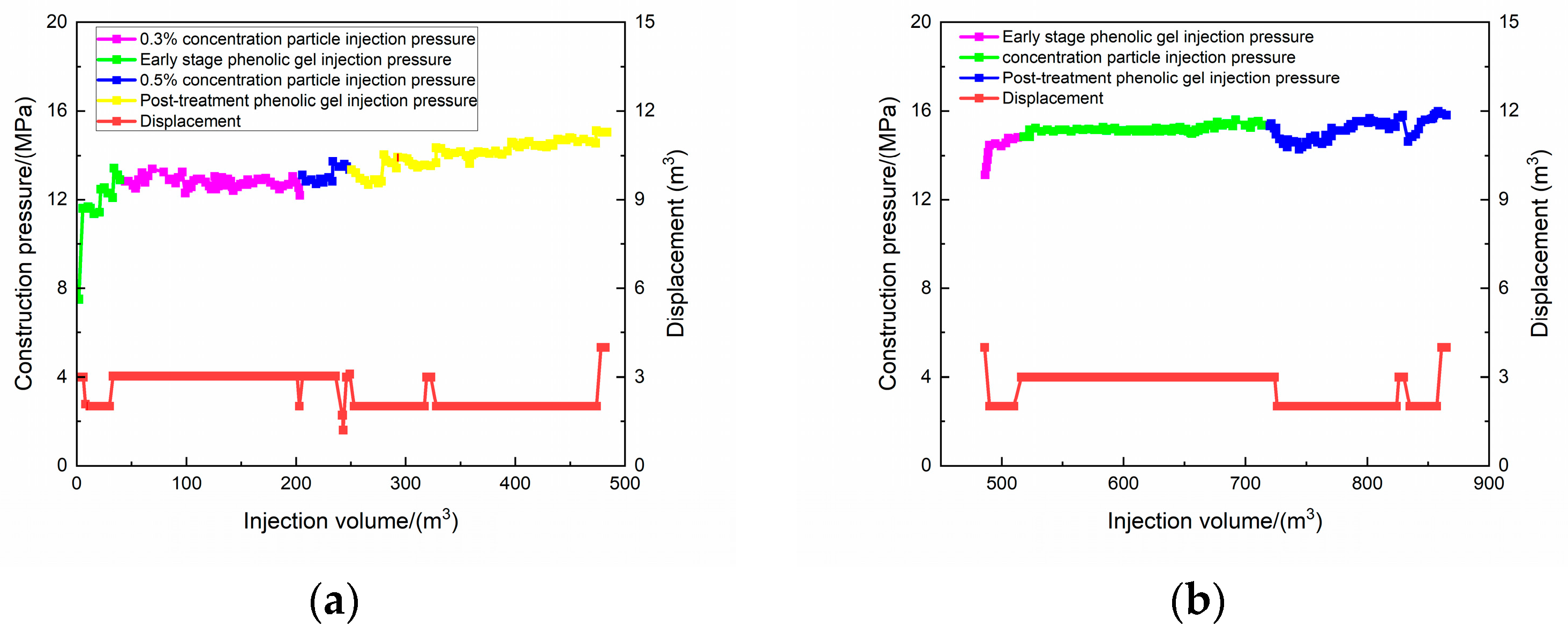
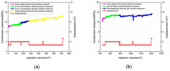
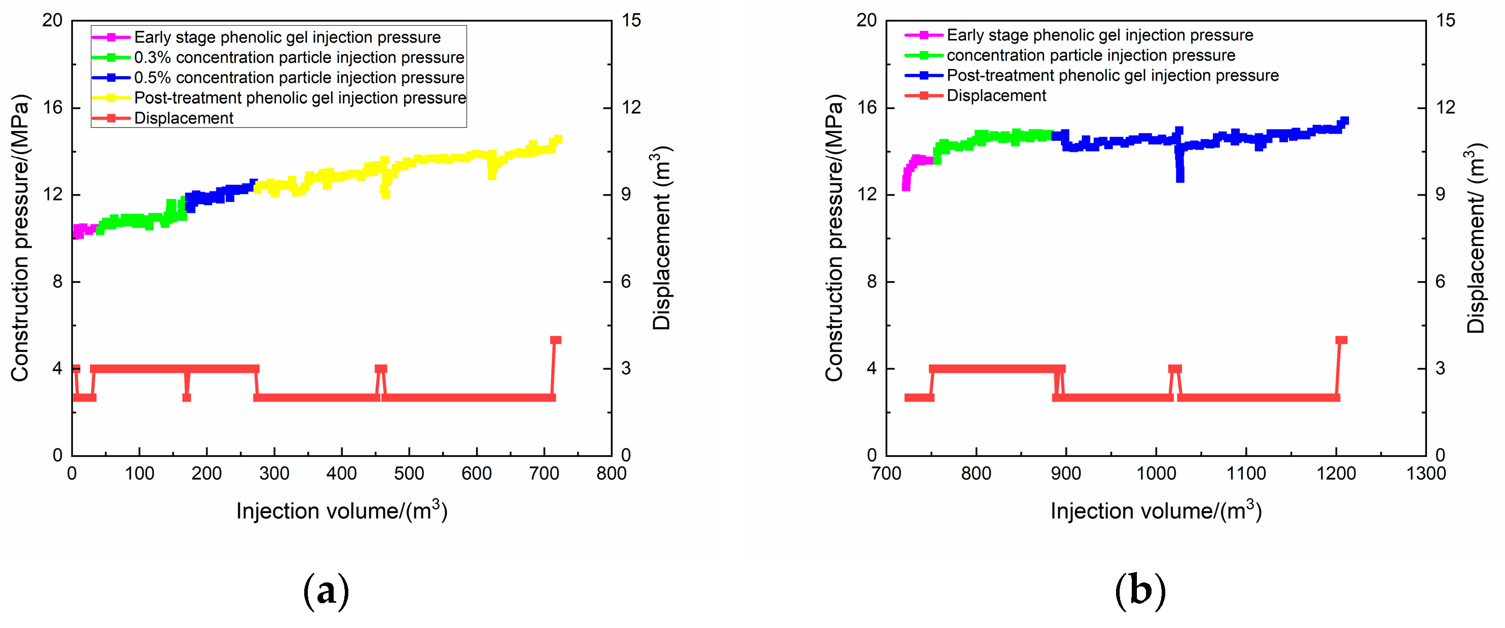
Well M2 is produced from the first and second intervals, with profile control implemented in both intervals. The designed dosage includes 0.9 t of profile control particles (0.2~0.5 mm) and 590 m3 of profile control gel: 0.6 t of particles and 168 m3 of gel for the first interval, and 0.7 t of particles and 240 m3 of gel for the second interval. For the second interval profile control (Figure 4a), the pressure increases by 2 MPa during gel injection, and stabilizes at 13 MPa during particle injection. No significant pressure rise is observed when increasing the particle concentration; the subsequent gel injection pressure continues to climb, ultimately stabilizing at approximately 15 MPa. For the first interval profile control (Figure 4b), the particle injection pressure stabilizes at approximately 15 MPa, demonstrating smooth particle injection throughout the process.
Figure 4.
Actual construction curve of well M2: (a) The second section of profile control; (b) The first section of profile control.
- (II)
- Well M3
Well M3 is produced from the first and second intervals, with profile control conducted in both intervals. The designed dosage comprises 1.1 t of profile control particles and 770 m3 of profile control gel: 0.4 t of particles (0.2~0.5 mm) and 320 m3 of gel for the first interval, and 0.4 t of particles (0.2~0.5 mm) + 0.3 t of particles (0.5~1 mm) and 450 m3 of gel for the second interval. For the second interval profile control (Figure 5a), the initial injection pressure is 10.2 MPa, rising steadily to 14.5 MPa (0.5 MPa below the pump pressure). The particle injection starts with a relatively high pressure but stabilizes subsequently, confirming smooth particle injection. For the first interval profile control (Figure 5b), the initial injection pressure is 13.2 MPa, rising steadily to 15.3 MPa (0.3 MPa above the pump pressure). The particle injection pressure remains stable in the early stage and increases in the later stage, demonstrating successful particle injection.
Figure 5.
Actual construction curve of well M3: (a) The second section of profile control; (b) The first section of profile control.
- (III)
- Well M4
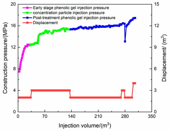
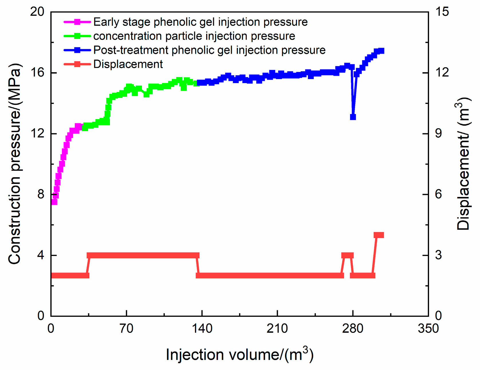
Well M4 is produced from the first, second, and third intervals, with profile control applied to the second interval (Figure 6). The designed dosage includes 0.5 t of profile control particles (0.2~0.5 mm) and 350 m3 of phenolic gel. The actual injected amount is 0.29 t of particles (0.3% concentration) and 192 m3 of thin gel (characterized by low initial viscosity and long crosslinking time). A sudden pressure surge occurs when approximately 50 m3 of particles are injected. It is inferred that interlayer channeling pathways and external casing channeling pathways are sealed by the presence of high-pressure water pockets, with overall smooth particle injection.
Figure 6.
Actual construction curve of well M4.
During the profile control of Well M4, an adjustment was required involving a significant reduction in the actual injection volume compared to the designed volume. The core reasons stem from two aspects: First, the reservoir conditions are complex. The well is rated as “poor” in profile control adaptability, featuring a large inner zone radius, a significant permeability ratio difference, and obvious interlayer and annular channeling pathways. Compared with wells with good adaptability, its seepage field distribution is more intricate. Second, there is insufficient adaptability of plugging agent injection. The initially designed particle concentration and gel viscosity failed to fully account for the high-pressure water coating effect, leading to an abrupt pressure rise at the initial injection stage and making it impossible to inject according to the originally designed volume.
4.4. Summary
① Profile control adaptability evaluation is a prerequisite for scheme design. For reservoirs with a large inner zone radius and significant permeability ratio difference, the combination of profile control and flooding should be prioritized over single profile control; ② For plugging agent design in complex reservoirs, dynamic adaptability must be strengthened. An injection strategy of “starting with low concentration and gradually increasing concentration” can be adopted to avoid injection interruption caused by abrupt pressure rise; ③ It is necessary to improve the dynamic monitoring and feedback mechanism during the injection process, conduct real-time tracking of pressure changes, and timely adjust parameters such as plugging agent concentration and viscosity to ensure the smooth implementation of the measures.
It should be pointed out that this study focuses on the synergistic relationship between plugging agent dosage design and formation heterogeneity, aiming to solve the problem of fuzzy dosage caused by unclear understanding of channeling channel. The properties of the plugging agent itself, such as particle concentration, temperature tolerance, and salt tolerance, belong to the category of plugging agent formulation screening and performance evaluation. In the field application of this study, the plugging agents used have passed the conventional compatibility and performance evaluation experiments (such as viscosity, gelation time, thermal stability, etc.) under the reservoir conditions of the target block in advance, ensuring their effectiveness under reservoir temperature and salinity. Therefore, when establishing the matching relationship between particle size and fracture opening, the default plugging agent performance parameters are within the effective range. Subsequent research can further couple performance parameters and dosage design to establish a more refined, comprehensive model.
5. Conclusions
Field tests of the proposed method were conducted in Jilin Oilfield, and its comprehensive advantages are remarkable: In terms of accuracy, it outperforms the profile control radius method and fuzzy method, and is comparable to the numerical simulation method, but without the high upfront investment required by numerical simulation; In terms of cost, it effectively reduces treatment costs through precise design of plugging agent dosage; In terms of operational feasibility, it balances simplicity and scientific rigor, making it more suitable for on-site promotion and application. Meanwhile, the method addresses the shortcomings of traditional methods that ignore the synergistic effect between reservoir heterogeneity and plugging agents and lack quantitative criteria. Through the “dual resistance zone” mechanism and dynamic coupling criterion, it provides quantitative theoretical support for the design of plugging agent dosage in high-water-cut reservoirs, resolving the long-standing design ambiguity of traditional methods. Combined with field applications and method comparisons, the quantitative correlation of “heterogeneity degree—plugging agent dosage—water control effect” in high-water-cut heterogeneous reservoirs is clarified, providing a scientific basis for dosage design. The proposed multi-dimensional synergistic design process balances scientificity and practicality, improving the feasibility of profile control and water plugging design schemes for similar reservoirs by more than 30%. Additionally, through the adjustment practice of special wells such as Well M4, the implementation principle of “evaluation first, then design, and dynamic adjustment” is summarized, offering experiential reference for subsequent profile control and water plugging measures in complex reservoirs. The proposed method is currently applicable to high-water-cut heterogeneous sandstone reservoirs with composite permeability characteristics in the Jilin Basin, with an applicable permeability range of 1~100 mD. The main conclusions are as follows:
- (1)
- Through quantitative identification of pressure and pressure gradient distribution characteristics in the seepage field via well test interpretation, the “dual resistance zone” control mechanism between injection and production wells is revealed. The synergistic optimization objectives of reconstructing the near-wellbore pressure drop funnel and regulating inter-well permeability differences after profile control are clarified. Field verification shows that the plugging agent dosage scheme designed based on this mechanism achieves a consistency of over 90% between well test interpretation results and construction performance, effectively reconstructing the seepage field.
- (2)
- Through systematic analysis of the reasonable profile control radius and the development radius of advantage channel, a dynamic coupling mathematical criterion and a determination method for the profile control radius are established. The development radius of advantage channel corresponding to particle plugging agents is 2.5 times the inner zone radius, and that for gel plugging agents is 2.0 times the inner zone radius. This resolves the plugging failure problem caused by traditional methods ignoring the physical differences between the two radii.
- (3)
- Based on the characteristic differences between particle and gel plugging agents, dosage calculation models (equivalent volume method for particles and modified volume method for gels) are constructed. The matching relationship between plugging agent particle size and fracture aperture is established, forming a multi-dimensional synergistic design system of “geological parameters—plugging agent properties—dynamic response.”
- (4)
- In the scheme design stage, core parameters such as inner zone radius and permeability should be prioritized via well test interpretation. For reservoirs with an inner zone radius >30 m and a permeability ratio difference >20, the combination of profile control and flooding is recommended instead of single profile control. In the construction stage, an injection strategy of “starting with low concentration and gradually increasing concentration” is adopted, with real-time pressure monitoring. If the abrupt pressure rise exceeds 5% of the pump pressure, the plugging agent concentration should be reduced, or the gel system switched promptly. In the effect evaluation stage, the dynamics of water cut and oil production within 6 months after profile control are closely tracked. If the water cut rebounds by more than 3 percentage points, secondary profile control parameter optimization should be conducted.
- (5)
- Future research should focus on the following aspects: Constructing multi-factor coupled mathematical models to quantitatively characterize the influence of profile control particle concentration on fracture matching relationships and deepen the study of plugging agent migration laws in complex fracture networks; Introducing artificial intelligence (AI) technology to train plugging agent dosage optimization models based on massive field data, achieving intelligent matching and real-time iteration of “geological parameters—dynamic response—dosage design”; Combining real-time monitoring technologies such as optical fiber sensing and microseismic monitoring to establish a dynamic tracking system for plugging agent migration trajectories, enabling real-time adjustment and precise control of plugging agent dosage; Conducting underground gelation kinetics experiments of profile control gels to optimize the 1.5× safety factor, further improving dosage design accuracy.
Author Contributions
Methodology, J.S.; Software, J.L. and L.J.; Validation, J.L. and L.J.; Formal analysis, T.L.; Investigation, J.W. (Jingting Wu), J.W. (Jie Wei) and Y.H.; Data curation, T.L.; Writing—original draft, J.W. (Jingting Wu) and J.W. (Jie Wei); Writing—review & editing, J.S. and Y.S. All authors have read and agreed to the published version of the manuscript.
Funding
This research was funded by [National Science and Technology Major Project, CCUS-EOR miscible and immiscible flooding technology and integrated demonstration of low permeability reservoirs in Songliao Basin] grant number [2025ZD1408101].
Data Availability Statement
The original contributions presented in this study are included in the article. Further inquiries can be directed to the corresponding author.
Conflicts of Interest
Y.S. was employed by PetroChina Jilin Oilfield Company. The remaining authors declare that the research was conducted in the absence of any commercial or financial relationships that could be construed as a potential conflict of interest.
References
- Li, K.; An, R.; Qu, C.; Wang, Y.; He, H. Optimization of temporary plugging and fracturing technology in ultra-low permeability reservoir. Petrochem. Ind. Appl. 2023, 42, 44–47+67. [Google Scholar]
- Zhou, F.; Yuan, L.; Liu, X.; Wang, B.; Li, M.; Li, B. Advances and key techniques of temporary plugging and diverting fracturing. Pet. Sci. Bull. 2022, 7, 365–381. [Google Scholar]
- Duan, P.; Li, X.; Bai, X.; Lei, G.; Huang, T.; Dong, Q. Method for extending the effective period of deep-water plugging measures for multi-stage filling of fractured water flooded oil wells. Oil Drill. Prod. Technol. 2024, 46, 466–478. [Google Scholar]
- Wang, T.; Jia, Y.; Lyu, G. The dosage of plugging agent in QHD32-6 oilfield well. J. Petrochem. Univ. 2015, 28, 58–61. [Google Scholar]
- Wang, S.; Zhang, Y.; Dong, L.; Chen, W. Calculation of fracture plugging agent quantity in low permeability reservoir. Fault-Block Gas Oil Field 2013, 20, 377–379. [Google Scholar]
- Liu, J.; Zhou, C.; Tian, Y.; Zhang, H.; Li, X.; Yan, T. Discussion on the calculation method of selective water shutoff agent dosage for bottom water reservoirs. Petrochem. Ind. Appl. 2016, 35, 74–76. [Google Scholar]
- Su, L.; Pang, P.; Da, Y. Usage optimization and field test of blocking agent for temporal-blocked re-fracturing in low permeability oilfield. Fault-Block Gas Oil Field 2014, 21, 114–117. [Google Scholar]
- Lin, Y.; Li, J.; Cheng, L.; Fang, Y.; Wang, Y.; Yang, Y. Characterization of remaining oil distribution in ultra-low permeability reservoirs during middle-high water cut by physical simulation combined with reservoir fine sculpture method. Oil Drill. Prod. Technol. 2024, 46, 175–188. [Google Scholar]
- Wan, X.; Li, P.; Wu, S. Numerical simulation of gel water shutoff in offshore horizontal wells with high water cut and large flow. Fault-Block Oil Gas Field 2023, 30, 466–474. [Google Scholar]
- Yu, T.; Sun, X.; Chen, Q. Experimental study on fracture plugging laws of different lithology reservoirs. Fault-Block Oil Gas Field 2024, 31, 345–350. [Google Scholar]
- Xu, B. Experimental study on distribution characteristics of remaining oil in vertical heterogeneous reservoirs by gel profile control. Pet. Geol. Recovery Effic. 2020, 27, 71–80. [Google Scholar]
- Zhao, H.; Liu, D.; Jiang, H.; Cao, L.; Zang, J.; Liu, Y.; Wang, N. A new method of reservoir profile control dynamic prediction based on the data-driven model. J. Yangtze Univ. (Nat. Sci. Ed.) 2021, 18, 60–69. [Google Scholar]
- Xie, K.; Yin, Y.; Liu, C.; Bai, R. Control strategies for dominant channels of water flooding based on time-varying characteristics of reservoirs. Sino-Glob. Energy 2024, 29, 60–69. [Google Scholar]
- Wu, L.; Wang, Y.; Zhang, J. Research and application of water control and plugging technology in low permeability bottom water reservoir. Drill. Prod. Technol. 2022, 45, 91–94. [Google Scholar]
- Xu, J.; Liu, G.; Wang, Y. Intrafracture temporary plugging and diversion fracturing technology suitable for tight reservoirs. Oil Drill. Prod. Technol. 2021, 43, 374–378. [Google Scholar]
- Luo, T.Y.; Fang, G.; Liang, L.J. New progress and application of chemical temporary plugging agents in petroleum engineering. Xinjiang Oil Gas 2019, 15, 79–87. [Google Scholar]
- Wang, J.; Kang, Y.; Zhang, D.; Dongjun, F.; Gang, C.; Lingyu, T. Advances in the application of temporary plugging agents for fracturing in unconventional reservoirs. Spec. Oil Gas Reserv. 2021, 28, 1. [Google Scholar]
- Liu, Y.; Wang, J.; Zhang, D.; Du, D.L.; Zhong, S. Development and application of the environmental response temporary plugging agent for well killing of CCUS oil reservoir. Fault-Block Oil Gas Field 2024, 31, 357–362. [Google Scholar]
- Fu, M.; Chen, P.; Li, Y.; Chen, L.; Liu, Z. Research and application of inorganic silicate gel sealer for thermal recovery of thick oil. J. Yangtze Univ. (Nat. Sci. Ed.) 2024, 21, 67–75. [Google Scholar]
- Wei, L.; Yang, X.; Chen, M.; Liu, H.; Fan, W.; Huang, L.; Peng, F.; Cao, K. Study and application of temporary plugging agent for turnaround fracturing in deep well. Spec. Oil Gas Reserv. 2022, 29, 154–159. [Google Scholar]
- Bai, Y.; Pu, W.; Jin, X.; Shen, C.; Ren, H. Review of the micro and Macro mechanisms of gel-based plugging agents for enhancing oil recovery of unconventional water flooding oil reservoirs. J. Mol. Liq. 2024, 399, 124–318. [Google Scholar] [CrossRef] [Scilit]
- Tang, K.; Su, Z.; Zhao, Y.; Xie, H.; Zhang, H.; Xu, Z.; Shi, C.; Wang, G.; Zhu, D. Water management and oil recovery improvement performance of high-strength preformed particle gels in fractured conglomerate reservoirs. Energy Fuels 2023, 37, 10287–10295. [Google Scholar] [CrossRef] [Scilit]
- Yao, L.; Quan, X.; Ma, J.; Wang, G.; Feng, Q.; Jin, H.; Yang, J. Development and Performance Evaluation of a Gel-Based Plugging System for Complex Fractured Formations Using Acrylic Resin Particles. Gels 2025, 11, 162. [Google Scholar] [CrossRef] [Scilit]
- Li, T.; Yang, W.; Wu, J.; Xing, P.; Xu, Q.; Liu, H.; Cao, G. Enhanced retention and synergistic plugging effect of multi-complexed gel on water-swellable rubber. Energies 2022, 15, 8096. [Google Scholar] [CrossRef] [Scilit]
- Telin, A.; Lenchenkova, L.; Yakubov, R.; Poteshkina, K.; Krisanova, P.; Filatov, A.; Stefantsev, A. Application of hydrogels and hydrocarbon-based gels in oil production processes and well drilling. Gels 2023, 9, 609. [Google Scholar] [CrossRef] [Scilit]
- Liao, Y.; Jin, J.; Du, S.; Ren, Y.; Li, Q. Research on performance evaluation of polymeric surfactant cleaning gel-breaking fluid (GBF) and its enhanced oil recovery (EOR) effect. Polymers 2024, 16, 397. [Google Scholar] [CrossRef] [Scilit] [PubMed]
- Yousufi, M.M.; bin Dzulkarnain, I.; Elhaj, M.E.M.; Ahmed, S. A perspective on the prospect of Pickering emulsion in reservoir conformance control with insight into the influential parameters and characterization techniques. Processes 2023, 11, 2672. [Google Scholar] [CrossRef] [Scilit]
- Yang, H.; Shen, J.; Liu, D.; Jiang, J.; Lv, Z.; Xu, Z.; Kang, W.; Su, W.; Turtabayev, S. Stabilization mechanism of viscoelastic polymer microspheres on N2 foam system. J. Mol. Liq. 2023, 392, 123–444. [Google Scholar] [CrossRef] [Scilit]
- Sun, L.; Zhang, Z.; Leng, K.; Li, B.; Feng, C.; Huo, X. Can supramolecular polymers become another material choice for polymer flooding to enhance oil recovery? Polymers 2022, 14, 4405. [Google Scholar] [CrossRef] [Scilit] [PubMed]
- Wang, X.; Wang, F.; Taleb, M.A.M.; Wen, Z.; Chen, X. A review of the seepage mechanisms of heavy oil emulsions during chemical flooding. Energies 2022, 15, 8397. [Google Scholar] [CrossRef] [Scilit]

Disclaimer/Publisher’s Note: The statements, opinions and data contained in all publications are solely those of the individual author(s) and contributor(s) and not of MDPI and/or the editor(s). MDPI and/or the editor(s) disclaim responsibility for any injury to people or property resulting from any ideas, methods, instructions or products referred to in the content. |
© 2026 by the authors. Licensee MDPI, Basel, Switzerland. This article is an open access article distributed under the terms and conditions of the Creative Commons Attribution (CC BY) license.