


Abstract
This paper presents a comprehensive study on the control law design for the turbine-to-ramjet mode transition in an adaptive-cycle turbine-based combined cycle (TBCC) engine, aiming to mitigate the persistent “thrust gap” challenge. An integrated conceptual configuration of a hypersonic vehicle with a parallel-duct TBCC system, which replaces the conventional turbofan with a three-bypass adaptive cycle engine (ACE), is proposed. High-fidelity performance models for both the ACE and the scramjet are developed, with a Kriging surrogate model employed to accelerate the computationally intensive ACE simulations during the transition. A co-optimization framework is established, defining a comprehensive performance index that balances thrust tracking accuracy and control smoothness under rigorous intake-engine flow matching constraints. Using sequential quadratic programming (SQP), the control schedules for the ACE’s variable geometries are optimized. Comparative analyses reveal that the ACE, with its flexible bypass management and multiple adjustable mechanisms, can actively adapt its airflow demand to match the restricted intake supply. Consequently, the optimized ACE-based TBCC reduces total airflow fluctuation during the Mach 3–3.5 transition from 106% (conventional turbofan baseline) to 42.5%, while maintaining required thrust. This work quantitatively demonstrates the superior flow-handling capability of adaptive cycle technology, providing a viable and effective solution for ensuring stable and efficient mode transition in future hypersonic TBCC propulsion systems.
1. Introduction
The development of variable cycle high-speed turbojet engines is increasingly important for aerospace propulsion, particularly for civil aircraft operating at Mach 4–5. This evolution is driven by the need for enhanced performance across diverse flight conditions. These engines can adjust their operating modes and geometrical configurations, presenting unique challenges and opportunities for control law design during mode transitions. A thorough understanding of the coupling and matching methods for multiple components, varying modes, and adjustable mechanisms is essential for improving engine efficiency, thrust retention, and overall performance.
In recent years, significant research has focused on variable cycle engines, particularly regarding modeling techniques, control strategies, and optimization methods. For instance, Jia et al. [1] developed a direct simulation method for the transition state of variable cycle engines using a steady-state inverse algorithm and implicit calculation methods, which facilitated the design of adjustment laws for geometrical parameters and fuel flow rates during mode transitions. Liu et al. [2] established a three-dimensional model of a dual bypass variable cycle compression system, analyzing flow patterns and matching characteristics during mode transitions through numerical simulation. Similarly, Song et al. [3] created a dynamic simulation method to evaluate the coupled regulation of bypass and variable stators during dynamic mode conversion. Luo et al. [4] employed a full three-dimensional model to investigate the effects of tuning the core-driven fan stage’s variable inlet guide vanes (VIGV) and the front variable area bypass injector (FVABI) on the internal flow and component matching in the compression system.
Performance evaluations have also gained attention, with Swaminathan et al. [5] conducting cycle analyses of low bypass ratio variable cycle engines, emphasizing the role of variable geometry mechanisms in component matching. Chen et al. [6] explored the performance of adaptive cycle engines with cooling air, while Wang et al. [7] proposed an integrated variable dimensional analysis method for rapid assessment of component-bypass coupling relationships. Liu et al. [8] examined the impact of second bypass backflow on variable cycle compression system matching during mode transitions. Wang et al. [9] obtained a high-fidelity characteristic map of the mode select valve (MSV) through three-dimensional CFD simulation and coupled this characteristic map into a variable-cycle engine performance calculation model in order to investigate the effect of the mode transition process on the engine performance.
In terms of control strategies for variable cycle engines, Hao et al. [10] optimized the control of geometrically adjustable mechanisms during the single-to-double bypass transition using a differential evolutionary algorithm, achieving smooth transitions. Wang et al. [11] formulated an overall control schedule based on game theory, resulting in coordinated thrust and rotor speed transitions. Chen et al. [12] implemented an enhanced linear quadratic regulator method to maintain stable engine demand flow throughout the transition process. Zhang et al. [13] proposed a general design method for mode transition control laws utilizing particle swarm optimization and sensitivity calculations, simplifying the adjustment of variable geometrical components. Zhao et al. [14] designed a closed-loop controller using a robust augmented linear quadratic regulator (ALQR) to minimize thrust fluctuations during mode conversion and introduced an optimization method for open-loop control scheduling based on Bessel curves. Furthermore, Jiang et al. [15] conducted a performance analysis of rapid thrust change transitions, validating their control law design through mode conversion and acceleration/deceleration strategies. Zhao et al. [16] utilized the Gray Wolf Optimizer (GWO) to obtain the optimal sequence of control variables that ensured a reduction in turbine outlet temperature with constant thrust. Xu et al. [17] proposed a hybrid optimization method combining differential evolution and Latin hypercube sampling to automatically determine optimal and continuous control schedules for adaptive cycle engines across different working modes, thereby enhancing performance and addressing stability concerns during mode transition.
Existing research has primarily focused on control strategies for multi-mode switching among various bypass configurations in variable cycle engines (VCEs) or adaptive cycle engines (ACEs) yet has largely overlooked their potential role as the turbine engine within a turbine-based combined cycle (TBCC) system to address the “thrust gap” issue during mode transition. This gap refers to the conflict between the high thrust demand and the limited available thrust during the transition phase. In a parallel-configuration TBCC, as the intake gradually redirects airflow to the ramjet flowpath, the turbine engine experiences a continuous reduction in available airflow, falling below the level required for conventional turbine operation. Confronted with this airflow mismatch, a conventional turbine engine can only reduce fuel flow and consequently rotational speed to lower its airflow demand, thereby avoiding compressor surge. However, this speed reduction inevitably leads to a drop in thrust, which fails to meet the high thrust requirement during the transition.
In contrast, variable and adaptive cycle engines offer distinctive advantages through their flexible mode-switching capability and multiple adjustable geometric mechanisms. During TBCC mode transition, these engines can actively adapt to the restricted airflow supply by modulating their own airflow demand. More importantly, within the limited airflow, they can direct a larger proportion of air into the high-pressure compressor, thereby optimizing energy distribution and thermal cycle efficiency to generate higher specific thrust, which effectively compensates for the thrust loss due to reduced mass flow.
To leverage these advantages, this paper first introduces an integrated conceptual design of a hypersonic vehicle powered by a TBCC system that incorporates an adaptive cycle engine in place of a conventional turbofan. A representative mode transition mission scenario is defined accordingly. In this study, the transition is treated as a quasi-static process—i.e., a progression through a series of equilibrium states—based on the consideration that the flight-time scale of the acceleration-climb segment (Mach 3.0–3.5) is considerably longer than the characteristic response times of engine rotors and actuators.
Subsequently, a computational model of the TBCC propulsion system and the transition process is developed, with the Kriging surrogate method employed to accelerate model evaluation. Using this framework, a comparative performance analysis between a conventional turbofan and a parameter-equivalent adaptive cycle engine during mode transition is conducted. Furthermore, the control law for the adaptive cycle engine throughout the transition is optimized using the sequential quadratic programming (SQP) method. The results quantitatively demonstrate the significant performance benefits offered by the adaptive cycle engine in mitigating the thrust gap in TBCC mode transition.
2. Adaptive Cycle TBCC Engine Performance Model
2.1. Hypersonic Vehicle/Adaptive Cycle TBCC Integrated Layout
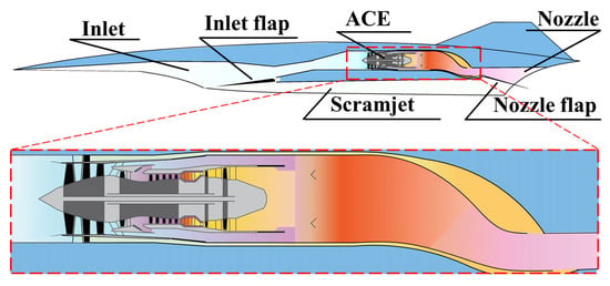
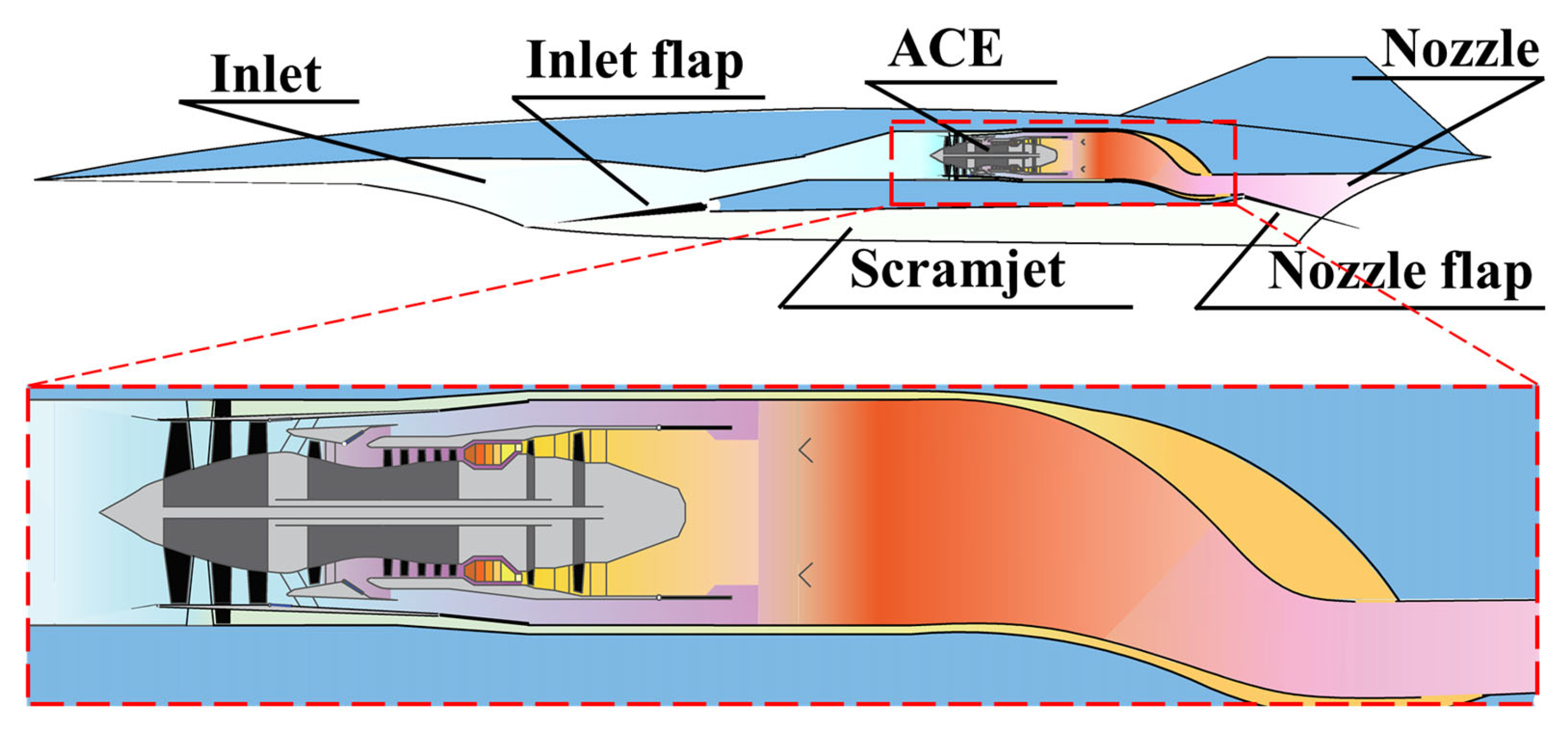
To quantitatively investigate the role of the adaptive cycle engine in mitigating the TBCC “thrust gap,” this paper proposes an integrated conceptual configuration of a hypersonic vehicle with an adaptive cycle TBCC propulsion system, as illustrated in Figure 1. The concept comprises a hypersonic vehicle airframe, a two-dimensional wedge-compression forebody/intake, the adaptive cycle engine, a scramjet, and a two-dimensional exhaust nozzle/aft-body. The adaptive cycle engine is housed in the turbine engine flow path, positioned closer to the vehicle centerline, while the scramjet is located in the ramjet engine flow path, nearer to the ventral side. Both paths share the external compression section of the two-dimensional wedge-compression forebody/intake and are separated by an intake adjustable flap integrated into the lip of the turbine stream’s lower wall.
Figure 1.
Adaptive cycle turbine-based combined cycle engine concept. Adapted with permission from [18].
Regarding the exhaust configuration, while both engine streams utilize the vehicle aft-body for external expansion, they are modeled with separate exhaust nozzles for thrust calculation. This simplification allows the performance models of the adaptive cycle engine and the scramjet to operate independently, with their net thrust outputs summed to obtain the total propulsion force. The integration of the two engines is therefore primarily governed by flow allocation at the shared intake, as detailed in Section 2.4.
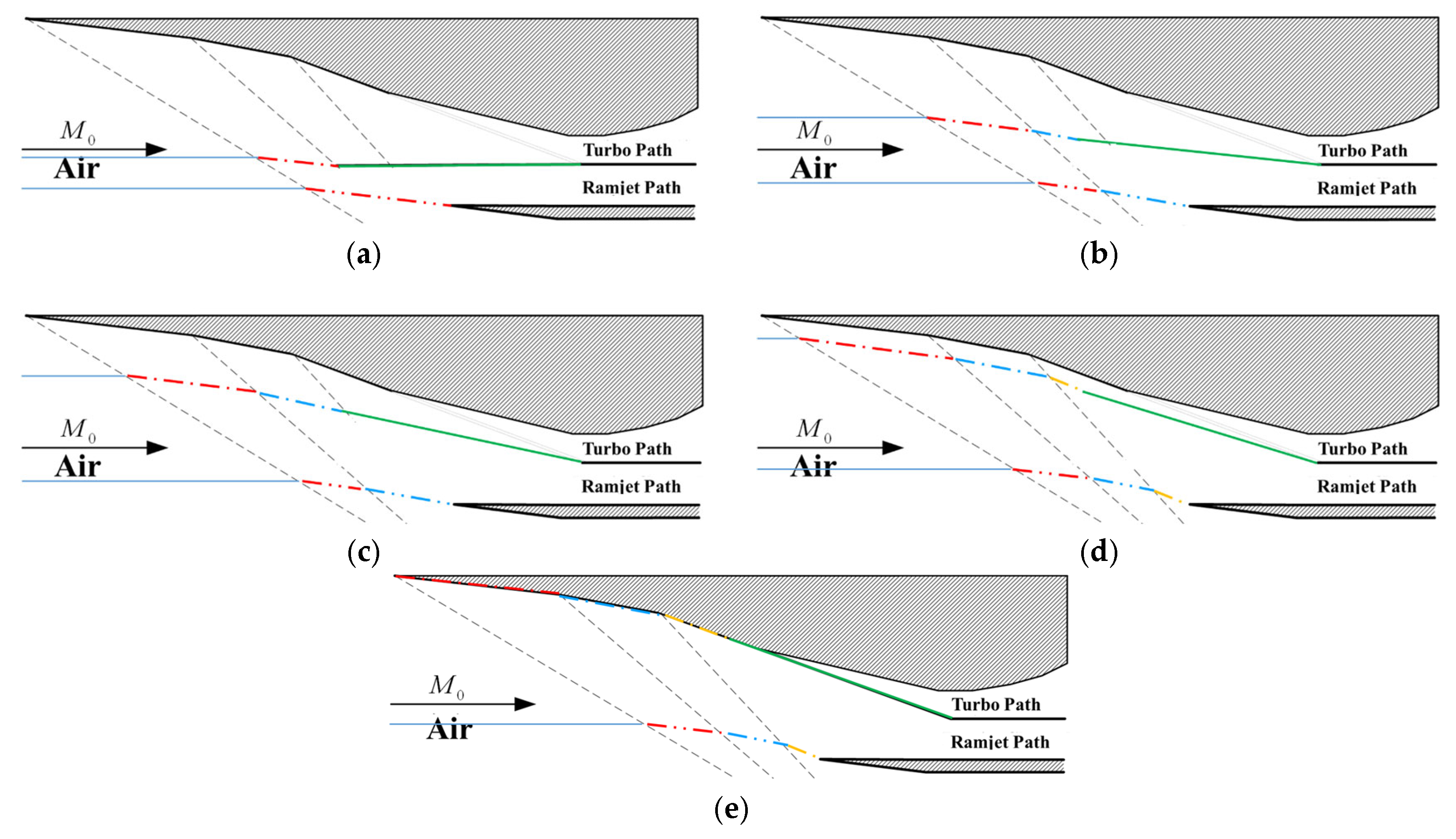
This adjustable flap is actuated according to the flight Mach number regime: it opens the turbine path and closes the ramjet path from Ma 0 to Ma 3, and opens the ramjet path while closing the turbine path from Ma 3.5 to Ma 6.
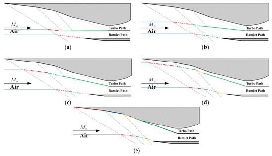
The turbine-to-ramjet mode transition occurs within the Mach 3 to 3.5 range. In this study, it is assumed that at the start of the transition, the intake adjustable flap has already opened the ramjet path and is in a horizontal position. As the Mach number increases, the flap gradually elevates to close off the turbine path, ultimately forming the complete intake for the scramjet. The adjustment is implemented in discrete steps, with each step corresponding to a 5° increment. The specific variable-geometry scheme of the forebody/intake during mode transition is detailed in Figure 2.
Figure 2.
The specific variable-geometry scheme of the forebody/intake during mode transition. (a) Phase 1; (b) Phase 2; (c) Phase 3; (d) Phase 4; (e) Phase 5. The green solid line represents the intake flap, and the other colored dash-dotted lines indicate the virtual streamline boundaries of the turbo path and ramjet path.
2.2. Adaptive Cycle Engine Performance Calculation Model
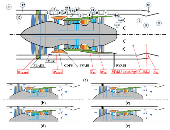
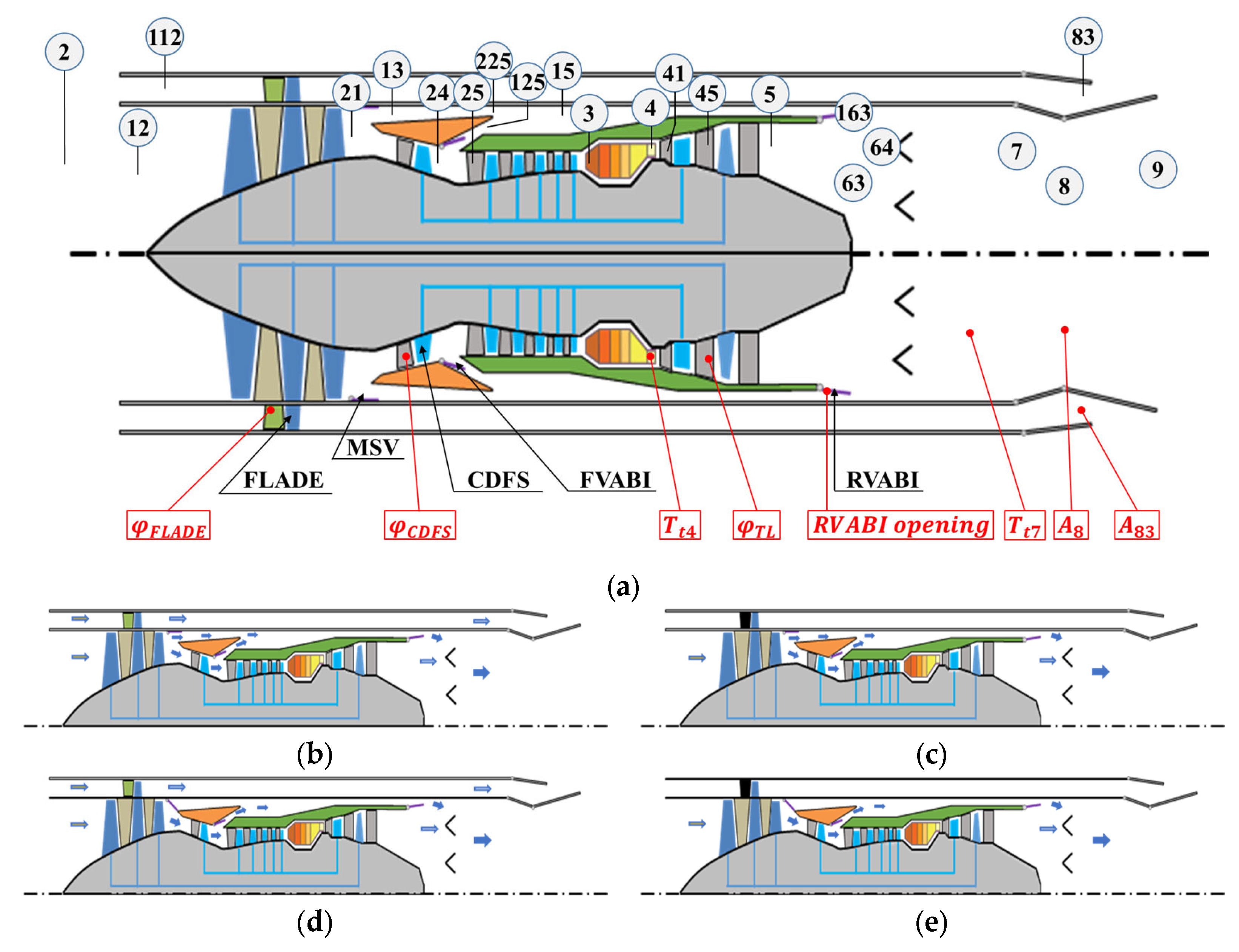
This study employs a three-bypass adaptive cycle engine. In contrast to variable cycle engines, the adaptive cycle engine investigated here incorporates FLADE (Fan on Blade) blades at the fan tip, forming a third bypass duct equipped with its own exhaust nozzle, as illustrated in Figure 3. In this configuration, the incoming airflow through the intake is divided into four separate streams: the third bypass airflow passing through the FLADE blades, the second bypass airflow traversing only the fan section, the first bypass airflow passing through both the fan and the Core-Driven Fan Stage (CDFS), and finally the core airflow entering the high-pressure compressor. By leveraging the unique arrangement of these three bypass streams, the adaptive cycle engine can flexibly modulate and match key parameters—such as total mass flow, bypass ratio, rotational speeds of the high- and low-pressure spools, exhaust temperature, and velocity—according to different operational states and mission requirements. This enables optimization for either maximum thrust or optimal fuel efficiency.
Figure 3.
Configuration and primary operating modes of the three-bypass adaptive cycle engine. (a) Primary adjustable geometric mechanisms and configurations; (b) M3 operating mode; (c) M2 CDFS operating mode; (d) M2 FLADE operating mode; (e) M1 operating mode.
The performance modeling approach for three-bypass adaptive cycle engine is similar to that of variable cycle engines, consisting of a zero-dimensional model built upon both design-point and off-design calculations. In the off-design analysis, the multidimensional Newton–Raphson iteration method is employed to iteratively determine the operating points of engine components by successively approximating their positions on the characteristic maps until the equilibrium conditions for all components are satisfied. Compared to conventional turbine engines or variable cycle engines, the adaptive cycle engine involves a more extensive set of component matching and balancing constraints, which include:
Although adaptive cycle engines involve a greater number of equilibrium constraints compared to conventional gas turbine engines, the fundamental principles remain consistent: satisfaction of mass flow continuity, rotational speed compatibility, power balance between compressors and turbines on the same shaft, and static pressure equilibrium at flow mixing interfaces. Depending on the operational bypass mode of the adaptive cycle engine, the corresponding equations from the aforementioned set of nine balance equations are selected to determine the actual overall engine performance. Since the operating point satisfying all equilibrium conditions is unique, the theoretically derived engine performance corresponds uniquely to each specific engine operating state and flight condition. The set of equilibrium equations to be solved for each bypass operating mode of the adaptive cycle engine is summarized in Table 1. Since detailed performance data for adaptive cycle engines has not yet been disclosed, the performance calculation model for the adaptive cycle engine presented in this paper was indirectly validated using the double-bypass variable cycle engine performance calculation model in the GasTurb 14 software. The details of this validation procedure can be found in our previous work [18].
Table 1.
The set of equilibrium equations to be solved for each bypass operating mode of ACE.
2.3. Scramjet Engine Performance Calculation Model
The performance of the scramjet is evaluated using a quasi-one-dimensional computational model. This approach divides the internal flow into sufficiently refined control volumes along the streamwise direction, solving the mass, momentum, and energy balance equations for each segment. As a result, detailed thermodynamic parameters along the flow path are obtained, enabling the determination of overall engine performance. For a comprehensive description of this quasi-one-dimensional scramjet performance model, refer to our previous research [18].
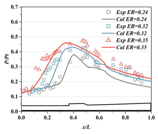
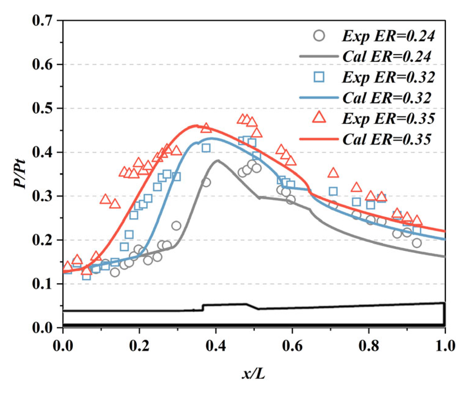
This model has been validated against experimental data from a direct-connect supersonic combustor test [19]. The validation was conducted for the identical combustor geometry under the same inflow conditions (total temperature: 840 K, total pressure: 0.82 MPa, combustor entrance Mach number: 2.02) as the experiment. A comparison between the model predictions and the experimental measurements for the wall pressure distribution is presented in Figure 4, which demonstrates satisfactory agreement and confirms the model’s reliability for performance estimation.
Figure 4.
Comparison of calculated and experimental results of pressure distribution in scramjet combustor.
The overall performance of the scramjet calculated using this validated model under the TBCC mission profile is shown in Figure 5.
Figure 5.
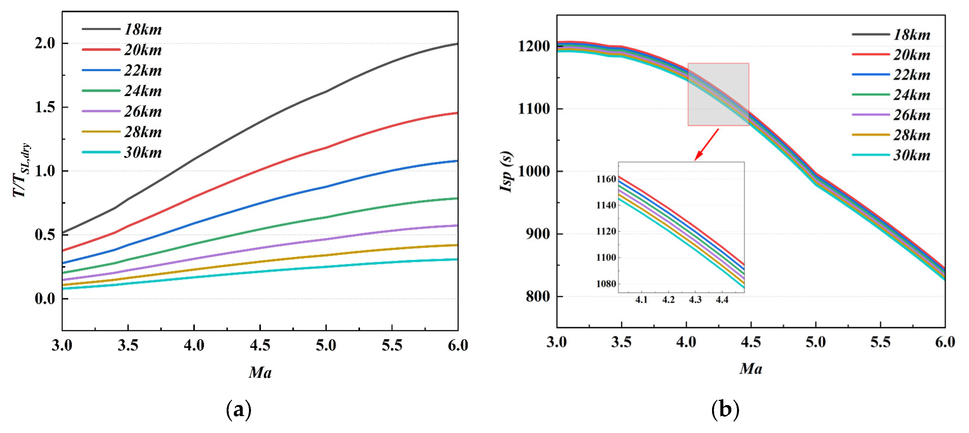
Overall performance of the Scramjet. (a) Thrust; (b) Specific impulse.
2.4. Calculation Method for Mode Transition
Ideally, thrust is expected to remain nearly constant during the turbine–ramjet mode transition to prevent significant changes in the flight condition of the vehicle. This imposes stringent requirements on the design of control laws and the matching of variable geometries, demanding high coordination accuracy and rapid response capabilities from the control system and adjustable mechanisms. In practice, however, it is challenging to achieve perfectly smooth thrust throughout the transition. Thrust fluctuations are inevitable and can perturb the flight condition, making it difficult to maintain stable velocity, altitude, and attitude. These variations in flight state may, in turn, affect engine operation, forming a strong aero-propulsive feedback loop.
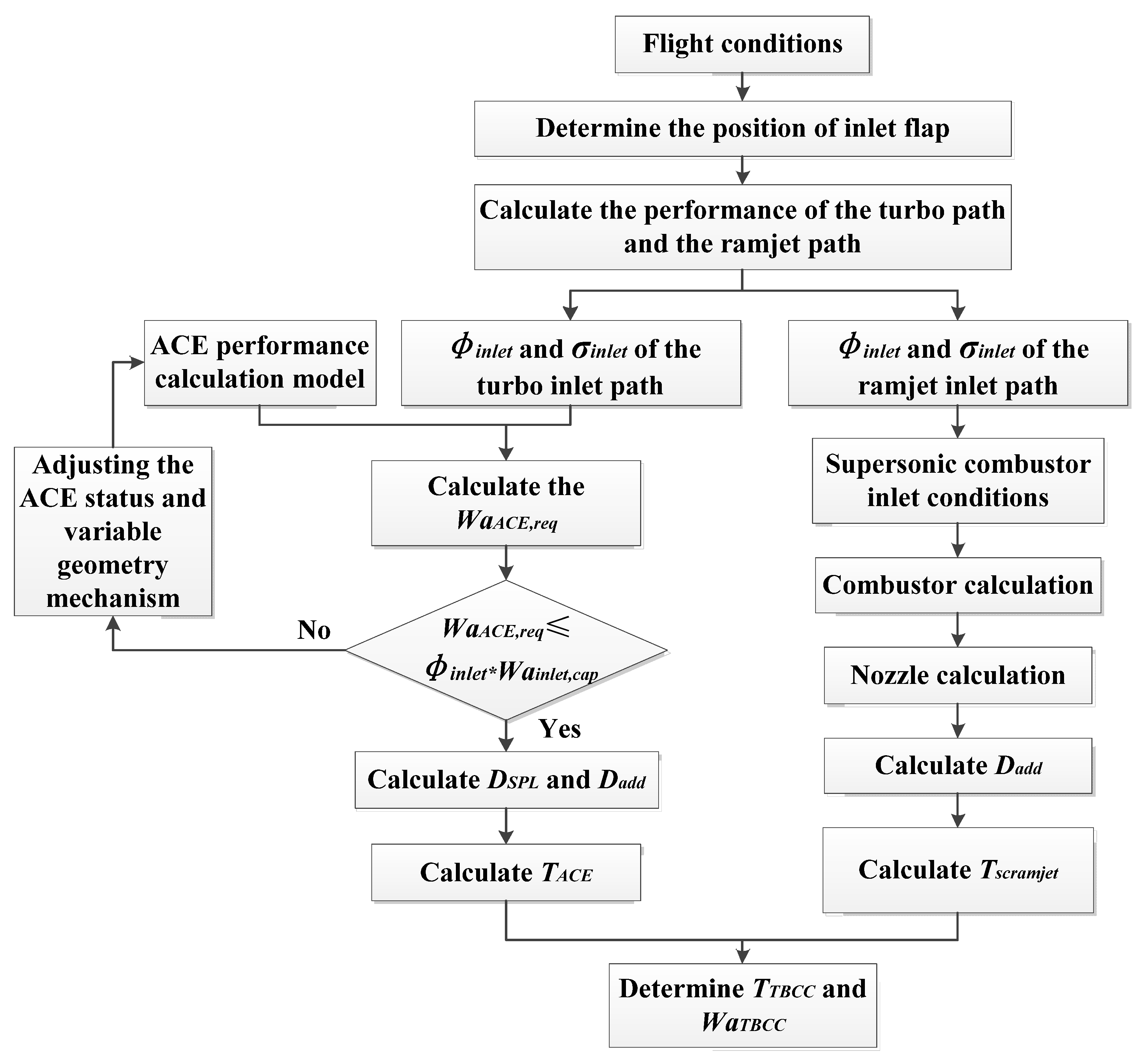
This study assumes that the mode transition takes place during a vehicle acceleration–climb segment within the Mach 3–3.5 range and at altitudes of 19–21 km. Under this premise, the transition is treated as a quasi-static process, discretized into a series of steady-state operating points along the flight Mach number. This approach is justified because the time scale of the vehicle acceleration–climb segment (on the order of tens of seconds) is considerably longer than the characteristic response times of engine rotors and actuators. Based on the integrated vehicle–propulsion mission performance analysis method [18], the required thrust for steady-level flight is computed at each velocity condition within this segment. The mode transition process is discretized according to flight Mach number, and the corresponding required thrust at each Mach number is set as the target total thrust to be jointly provided by the adaptive cycle engine and the scramjet during the transition. The specific computational procedure is summarized in Figure 6.
Figure 6.
Calculation process for TBCC mode transition considering intake/engine flow matching.
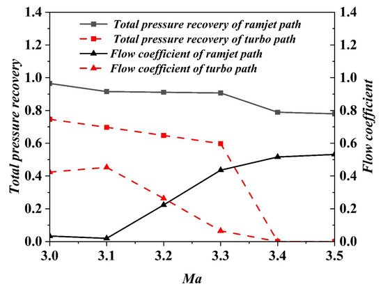
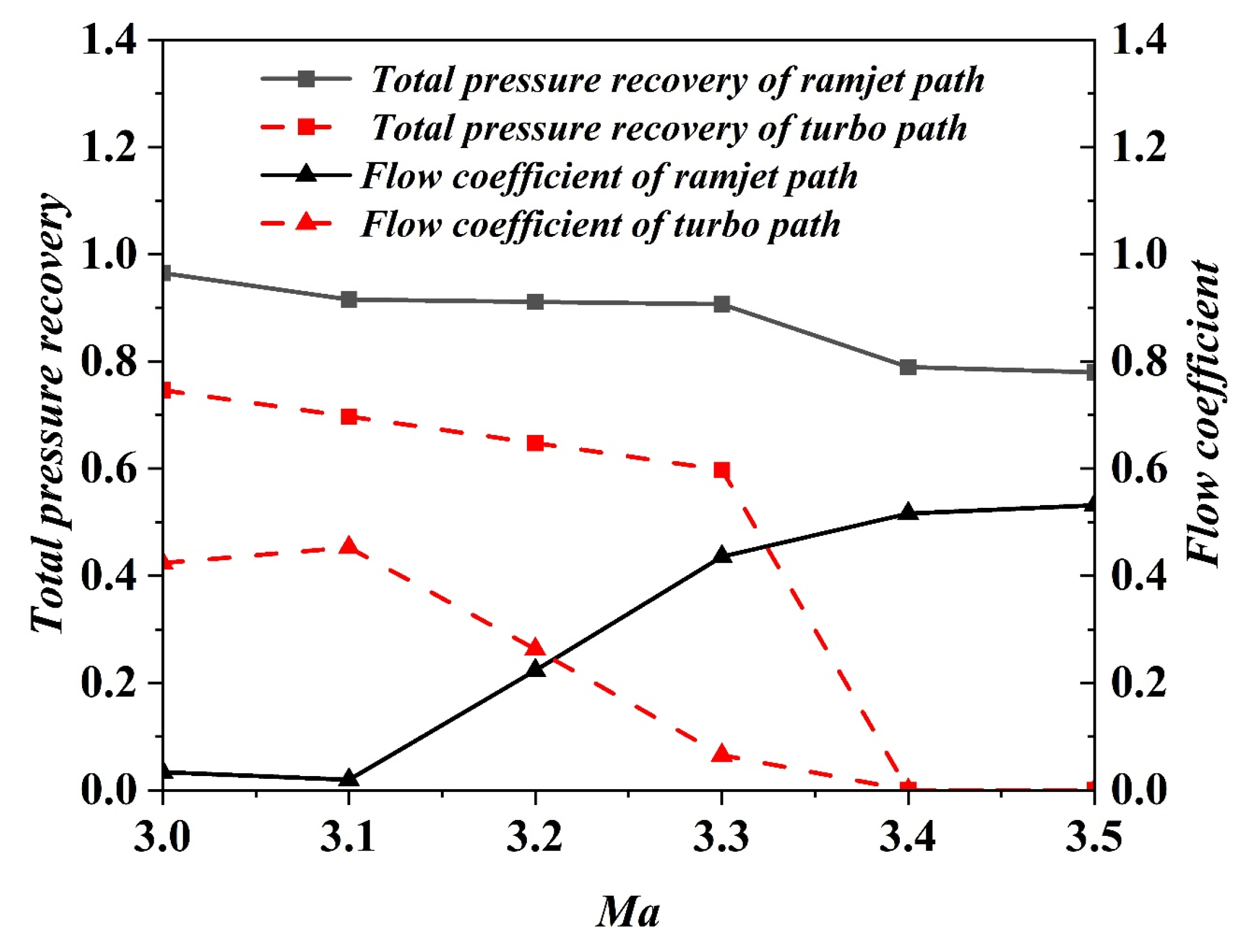
The following describes the modeling approach for the combined operation of the two engines with the shared intake. During the computation, the intake adjustable flap angle is first determined based on the flight Mach number, followed by the calculation of the flow coefficient and total pressure recovery coefficient for both the turbine and ramjet intake path. These intake parameters establish the available airflow for each propulsion stream. Performance calculations are then conducted separately for the ACE within the turbine path and the scramjet within the ramjet path.
The core of the combined operation lies in matching the engine demand to the intake supply. For the ACE in the turbo path, its required airflow is initially obtained by solving its equilibrium equations. Since the ACE is a self-aspirating engine, a flow compatibility constraint between and the intake’s available flow must be enforced. If , the ACE’s operating state and adjustable geometries are iteratively adjusted to reduce its airflow demand until the condition is satisfied. This iterative adjustment represents the active coordination between the engine control and the intake’s flow delivery capability. If , the excess flow is treated as spillage. The spillage drag and additive drag of the turbo intake are then computed. The installed thrust of the ACE is derived from its performance model, accounting for these intake drags.
For the scramjet in the ramjet path, the process is simpler because its operation is flow-controlled. Its actual airflow is exactly equal to the available flow from the ramjet intake . Its performance is calculated directly based on this inflow, and its installed thrust is obtained by subtracting the ramjet intake’s additive drag .
Finally, the total installed thrust and actual total airflow of the TBCC system are obtained by combining the outputs from both flow paths. These values are then compared against the required total thrust for mode transition at the given flight Mach number to assess whether the performance meets the mission demand.
Furthermore, the adjustment law for the intake adjustable flap during mode transition is defined as follows: for every 0.1 increase in flight Mach number, the flap is raised by 5°, until a total deflection of 20° is reached, at which point the turbine path is fully closed. Using the variable-geometry contour of the forebody/intake and shock relation calculations, the intake performance characteristics are derived, as shown in Figure 7.
Figure 7.
Performance characteristics of parallel TBCC intake.
2.5. Kriging Model for Adaptive Cycle Engine
The performance model of the adaptive cycle engine involves numerous input variables, complex equilibrium equations, and high sensitivity to initial iteration values. Especially when simulating the mode transition process, which operates far from the design point, numerical convergence is often difficult to achieve and frequently requires manual adjustment of initial guesses. This limitation severely restricts systematic analysis and optimization of the transition process. To address this, the present study employs the Kriging method to construct a surrogate prediction model for engine performance during mode transition, based on extensive sample data generated from the established performance model, thereby enabling efficient and robust exploration and optimization in subsequent work.
Originating from geostatistics, Kriging is a Gaussian process-based interpolation technique used to estimate attributes at unsampled locations from known observations. As a global response surface method, it characterizes nonlinear relationships between design variables and responses via a covariance function, achieving accurate interpolation in high-dimensional spaces with limited samples. In addition to its strong nonlinear fitting capability, Kriging provides probabilistic uncertainty estimates for predictions, making it widely applicable in surrogate modeling, Bayesian optimization, and uncertainty quantification. For highly nonlinear, high-dimensional numerical simulations such as aero-engine performance models, Kriging has demonstrated notable suitability and reliability [20].
Assume the original computational model is expressed as y = f(x), where represents a d-dimensional input vector and y is a scalar output. Given n sample points and their corresponding responses obtained from the original model, the Kriging model can be formulated as follows:
where is the predicted value for the sample point; is the deterministic global trend function, typically taken as a constant or a polynomial; is a stationary Gaussian process with zero mean, whose covariance is defined as
Here, is the process variance; is a parameterized correlation function with hyperparameter , which governs the spatial correlation—i.e., the similarity between responses at two sample points. A common form of this function is the Gaussian correlation:
Here, is the correlation parameter for the k-th dimension, typically learned from the data via maximum likelihood estimation. A large indicates a stronger influence of that input dimension on the output.
Given the sample data (X, y) and the correlation hyperparameters , the Kriging prediction for new points derived as the best linear unbiased predictor conditional on the observed data. Define the correlation matrix of the sample points as:
The correlation vector between the new point and all sample points as
For a constant global trend , generalized least squares gives , where is an n-dimensional vector of ones. The Kriging prediction can be interpreted as the global trend plus a locally weighted correction based on the residuals at the sample points:
The mean squared error (MSE) of the prediction is
Here, . This MSE is zero at the sample point and increases in regions far from them, providing a quantitative measure of prediction uncertainty.
Based on the methodology outlined above, a Kriging surrogate model was constructed for the adaptive cycle engine performance model described in this paper, specifically for the mode transition segment within the Mach 3–3.5 range. The model’s input and output variables include
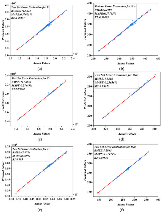
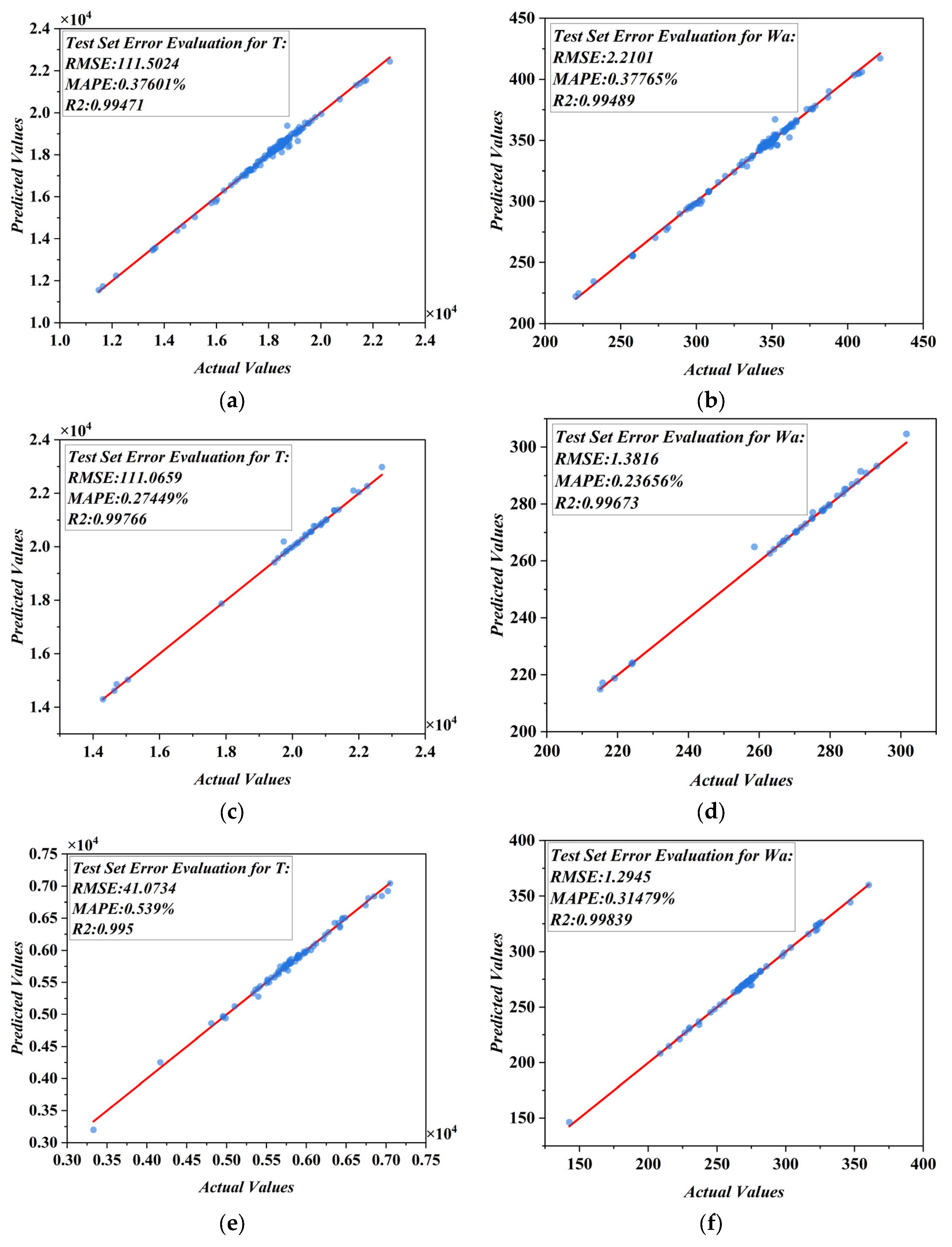
Figure 8 presents the predictions of the established Kriging surrogate model for the thrust and airflow objective functions of the adaptive cycle engine over the Mach 3–3.5 range, using the test dataset. The evaluation metrics indicate that the surrogate model constructed with the Kriging method achieves highly satisfactory prediction accuracy.
Figure 8.
The predictions of the established Kriging surrogate model for the thrust and airflow objective functions of the adaptive cycle engine over the Mach 3–3.5 range. (a) Thrust prediction results for M2 FLADE mode with afterburner; (b) Airflow prediction results for M2 FLADE mode with afterburner; (c) Thrust prediction results for M1 mode with afterburner; (d) Airflow prediction results for M1 mode with afterburner; (e) Thrust prediction results for M1 mode; (f) Airflow prediction results for M1 mode.
3. Mode Transition Calculation Results and Discussion
3.1. Conventional Turbofan TBCC Mode Transition
To compare the performance, overall thrust retention, and flow preservation capability of an adaptive cycle engine against a conventional turbofan during TBCC mode transition, the transition process was first simulated for a conventional turbofan designed with parameters equivalent to those of the adaptive cycle engine. Detailed design parameters for both engine types are listed in Table 2. It should be noted that the component pressure ratios, efficiencies, and other design parameters of this turbofan under sea-level static, dry-thrust conditions are identical to those of the adaptive cycle engine operating in its M1 mode under the same sea-level static, dry-thrust condition.
Table 2.
Detailed design parameters for conventional turbofan and ACE.
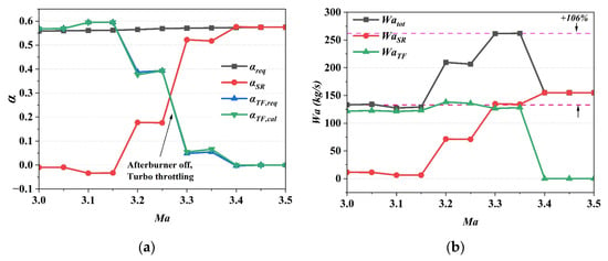
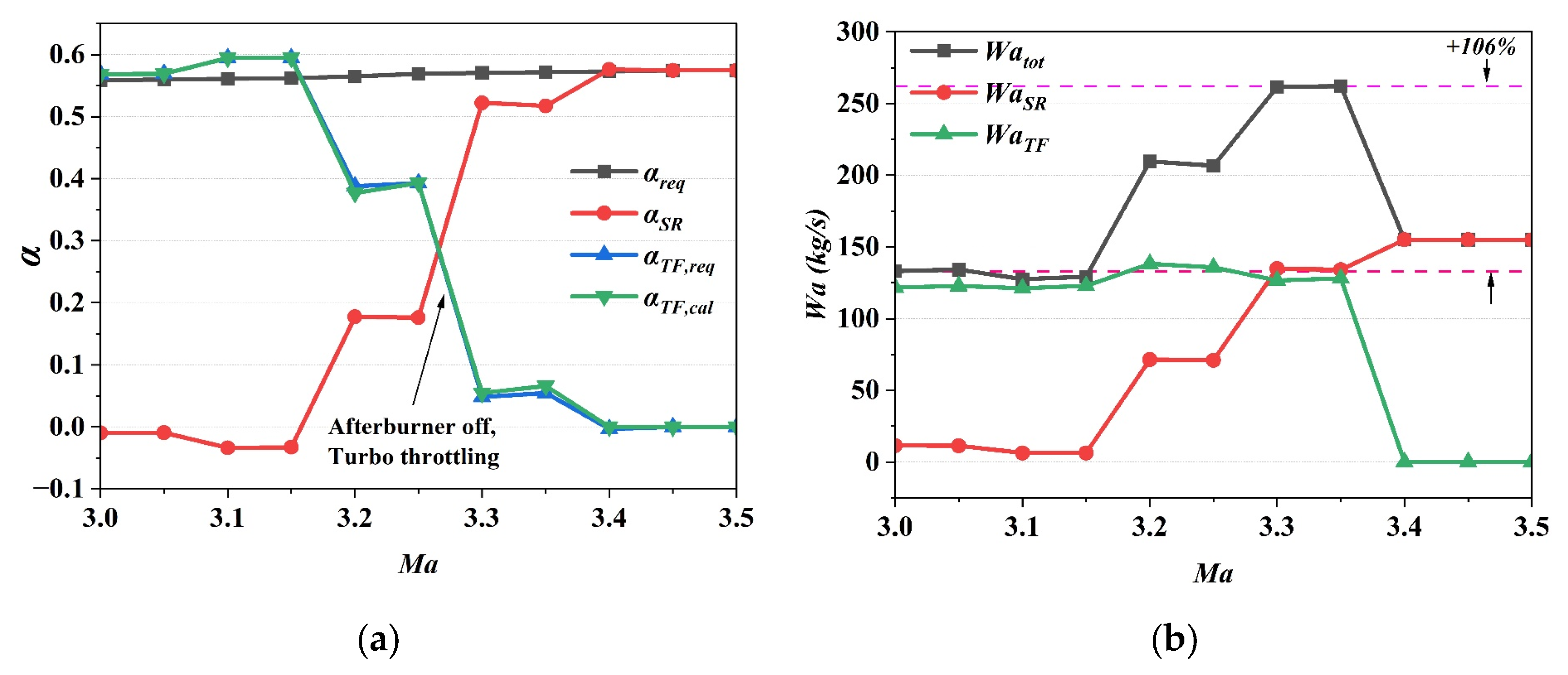
For a conventional turbofan-based TBCC, the parameter distribution at steady-state points during an ideal mode transition process—neglecting flow matching considerations—is illustrated in Figure 9. In this scenario, while the turbofan’s thrust decreases progressively and the scramjet’s thrust increases accordingly, resulting in a total thrust that meets mission requirements, the overall intake flow exhibits significant fluctuations.
Figure 9.
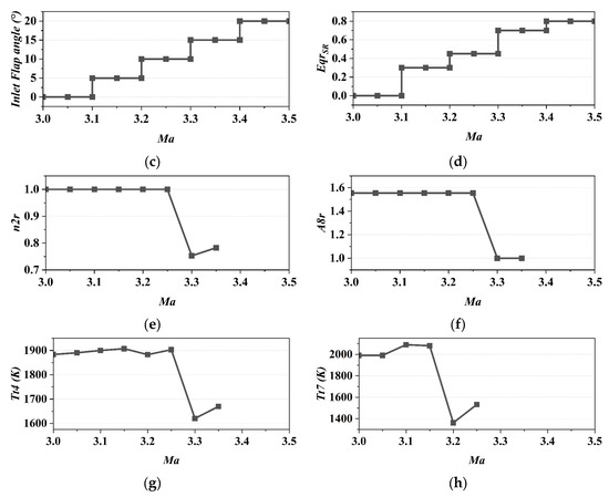
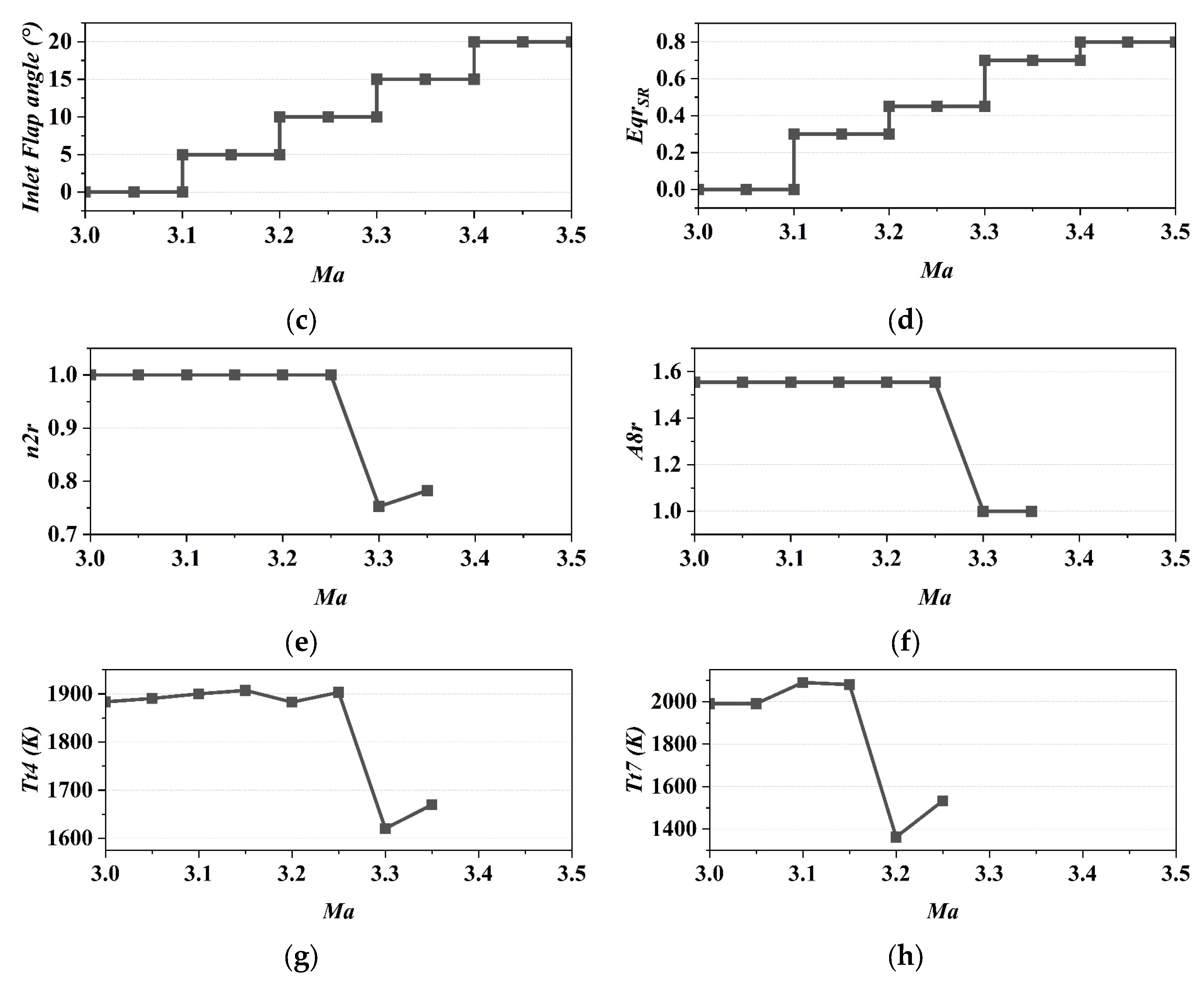
Variations in performance and control parameters of the conventional turbofan TBCC during mode transition. (a) Thrust versus required thrust; (b) Turbine stream and total airflow variations; (c) Control schedule of the intake adjustable flap angle; (d) Control schedule of the scramjet equivalence ratio; (e) Relative rotational speed of the turbofan high-pressure spool; (f) Core nozzle throat area of the turbofan; (g) Turbofan main combustor outlet temperature; (h) Turbofan afterburner temperature.
In reality, the reduction in the capture area of the low-speed stream directly restricts its maximum theoretical flow capture capacity. The scramjet’s airflow is determined by flight conditions and the intake flow coefficient, whereas the turbofan—being a self-aspirated propulsion device—has a demanded airflow governed by rotor speed, throttle setting, and compressor characteristics. A mismatch between the intake supply and engine demand leads to a sustained shortfall in available airflow, which can trigger unstable phenomena such as compressor surge or even intake unstart.
To ensure flight safety and propulsion stability, the turbofan must actively reduce its rotational speed and power setting to adapt to the continuously decreasing airflow supply. This adjustment inevitably results in a loss of thrust, creating what is commonly referred to as a “thrust gap”.
The performance limitations summarized in Figure 9 highlight a fundamental constraint of conventional turbofan-based TBCCs: the inability to actively adapt airflow demand during transition. To overcome this, an alternative propulsion architecture capable of real-time flow matching is required. Section 3.2 examines such an approach using an adaptive cycle engine, with results presented in Figure 10, to directly compare its transition performance against the conventional baseline.
Figure 10.
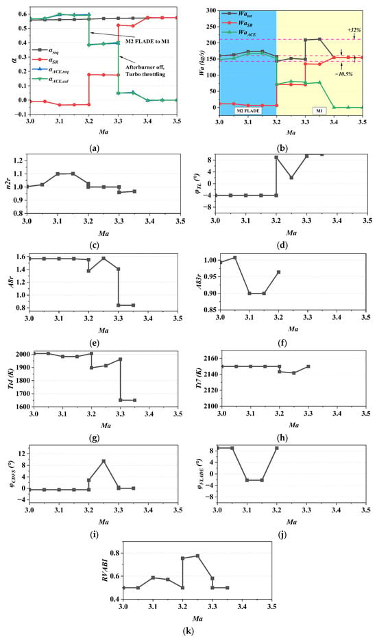
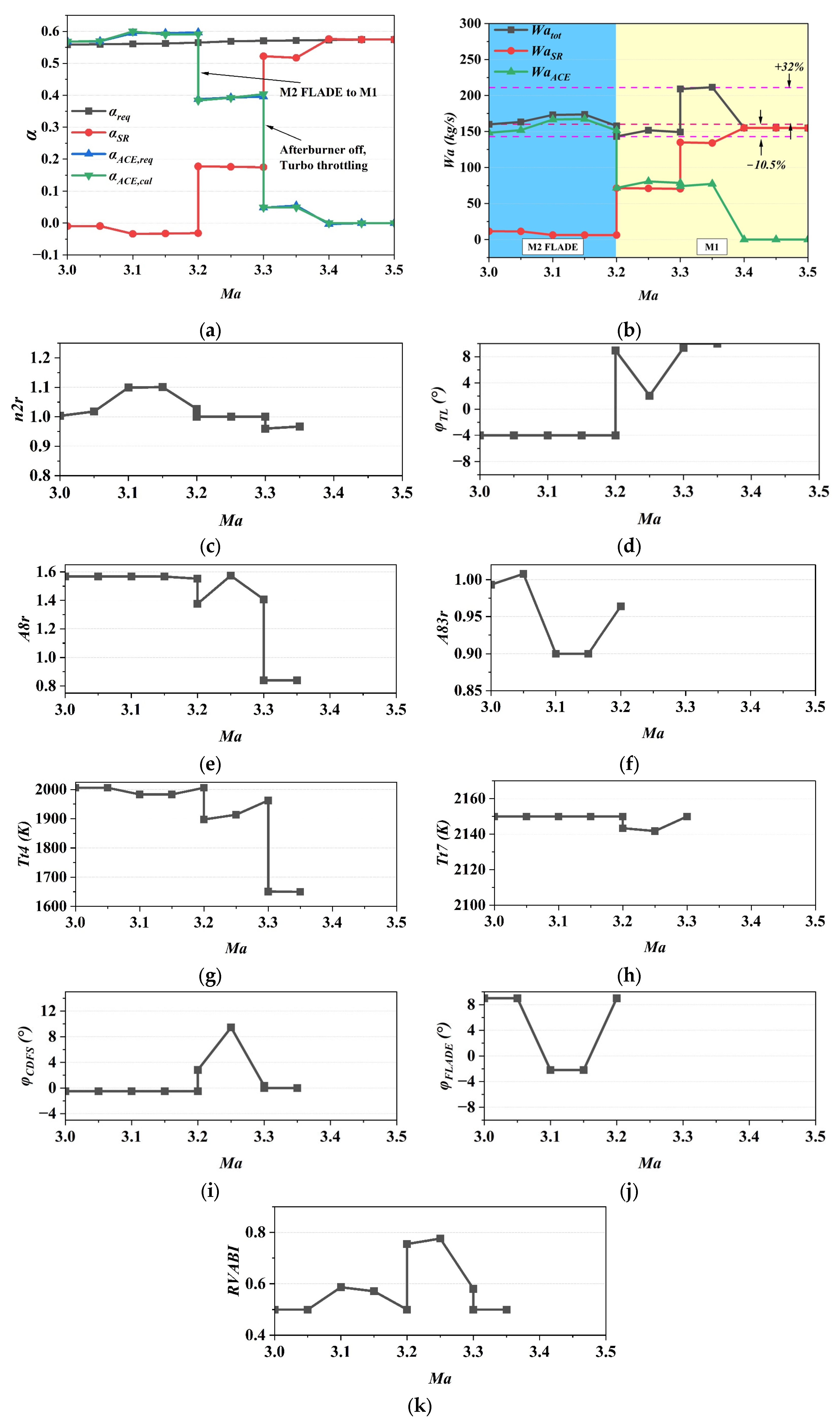
Multi-Variable coordinated control and performance response of the adaptive cycle engine TBCC during mode transition. (a) Thrust versus required thrust; (b) Turbine stream and total airflow variations; (c) Relative rotational speed of the ACE high-pressure spool; (d) Low-pressure turbine guide vane angle; (e) Main exhaust nozzle throat area; (f) FLADE bypass nozzle exit area; (g) Main combustor outlet temperature; (h) Afterburner temperature; (i) CDFS variable guide vane angle; (j) FLADE variable guide vane angle; (k) Rear Variable Area Bypass Injector (RVABI) opening.
3.2. Adaptive Cycle TBCC Mode Transition
By contrast, the adaptive cycle engine offers a promising solution to the aforementioned challenges through its controllable bypass ratio, pressure ratio, and multiple sets of adjustable geometric mechanisms. By implementing coordinated control and optimization of its variable components—such as the core-driven fan stage, mode selector valves, and exhaust nozzles—the adaptive cycle engine can actively adjust its airflow demand during mode transition to achieve precise matching with the intake’s supply capacity.
Theoretically, a TBCC system based on an adaptive cycle engine is capable of designing a mode transition schedule with superior thrust and flow retention, while strictly adhering to intake–engine airflow matching constraints. This provides key technical support for overcoming the limitations of the conventional “thrust trap”.
Based on the intake–engine flow matching methodology proposed in this paper, the following optimization objective is defined for the specific scenario of mode transition:
Under all given constraints, the installed thrust output of the propulsion system should approximate the mission-required thrust as closely as possible, while ensuring smooth actuation of all adjustable engine mechanisms. To this end, a comprehensive performance index J is formulated as the weighted sum of squares of the thrust tracking error and the incremental adjustments of the adjustable mechanisms between successive states. The mathematical expression is given as follows:
where k denotes discrete state points during the mode transition process, defined based on flight velocity in this study; and represent the actual installed thrust and the required thrust at the k-th state point, respectively; refers to the control input of the i-th adjustable geometric mechanism at the k-th state; the weighting coefficient = 0.4 was selected based on a preliminary parametric analysis to achieve a balanced compromise between thrust-tracking accuracy and control smoothness for the present mission profile.
During the mode transition process, the control strategies for the intake adjustable flap and the scramjet follow the predefined policy outlined in Figure 9c,d, implementing stepwise adjustments based on flight Mach number. This study assumes that the adaptive cycle engine enters the transition phase while operating continuously in the M2 FLADE mode with afterburning. This initial mode is selected for two critical reasons. First, during the high-Mach acceleration-climb segment prior to transition, the vehicle’s sustained high-thrust demand requires prolonged afterburning operation; the independent FLADE bypass stream provides essential nozzle cooling to prevent thermal damage under these conditions. Second, the M2 FLADE configuration maintains the high afterburning thrust needed for acceleration while fulfilling this practical thermal-management constraint.
As the transition progresses and the turbo path gradually closes, the engine shifts to the M1 mode with afterburning to maintain total thrust under increasingly constrained airflow. This mode change is essential because the M1 architecture, by closing the third bypass, intrinsically reduces the engine’s overall flow demand while preserving a high-pressure core stream. Thereby, it aligns the engine’s demand with the shrinking intake supply without sacrificing cycle pressure. Furthermore, as the airflow supply from the turbo path continues to diminish and the scramjet’s thrust progressively increases, the adaptive cycle engine sequentially transitions through M1 mode with minor afterburning, maximum power mode, and finally to throttled operation before shutdown. This staged power-down results directly from the optimization that prioritizes intake-engine flow matching; each step represents an equilibrium point where the engine’s reduced flow demand is balanced against the available supply. The variable geometries—such as the FLADE and CDFS vane angles and the RVABI opening—are actively coordinated throughout to manage the internal flow redistribution that enables these mode transitions.
In addition to the optimization objectives and control law constraints, the following control boundaries are imposed on the adjustable geometric mechanisms to ensure stable vehicle operation throughout the mode transition:
Here, RVABI denotes the opening of the Rear Variable Area Bypass Injector. When RVABI = 1, the ejector is in its design-positioned state. When RVABI < 1, the outer bypass area at the mixer inlet decreases, and vice versa. , and represent the vane angles of the FLADE, the Core-Driven Fan Stage (CDFS), and the Low-Pressure Turbine, respectively.
It should be noted that when the adaptive cycle engine switches between the M2 FLADE and M1 modes, step changes in thrust and airflow are inevitable. Therefore, the transition between bypass modes of the adaptive cycle engine must be scheduled to occur concurrently with adjustments to the intake adjustable flap and the scramjet equivalence ratio. This synchronous regulation of the three systems ensures that the total airflow and total thrust of the combined propulsion system do not exhibit significant fluctuations in steady-state performance.
In addition to optimizing the comprehensive performance index J, the following continuity constraint must be imposed:
Figure 10 illustrates the steady-state performance changes of the adaptive cycle TBCC during mode transition process, along with the adjustment patterns of its variable geometry mechanism. Based on the aforementioned optimization objectives and constraints, the Sequential Quadratic Programming (SQP) method was employed to optimize the turbine–ramjet mode transition process of the TBCC system, along with the control of the adjustable geometric mechanisms in the adaptive cycle engine. Within the Mach 3.0–3.2 range, the adaptive cycle engine operates in the M2 FLADE mode. During this phase, the scramjet is not yet capable of generating positive thrust; therefore, the adaptive cycle engine must provide the total required thrust for the vehicle while overcoming the internal flow resistance induced by the scramjet. As the vehicle accelerates beyond Mach 3.2, the intake adjustable flap opens further, allowing the scramjet to increase its equivalence ratio and begin producing positive thrust. Simultaneously, the adaptive cycle engine switches immediately to the M1 mode to redirect airflow—originally destined for the FLADE bypass—into the scramjet duct. Upon further acceleration to Mach 3.3, as the scramjet starts to assume the primary role in meeting the vehicle’s thrust demand, the adaptive cycle engine deactivates its afterburner and rapidly reduces its power setting to a relative speed of n2r = 0.96, thereby further lowering its own airflow requirement.
A direct comparison with the conventional turbofan baseline (Figure 9) reveals the fundamental improvements offered by this ACE-based strategy. First, regarding overall performance, the total airflow fluctuation (Figure 10b) is significantly dampened compared to the severe oscillation in the conventional case (Figure 9b). Second, the underlying control mechanism shifts from passive reaction to active management. For the turbofan, control variables (e.g., HPC speed, nozzle area in Figure 9e,f) react monotonically to the deteriorating intake condition. In contrast, the ACE proactively coordinates its multiple variable geometries (Figure 10c–k). The adjustments of the FLADE and CDFS vane angles (Figure 10i,j) and the RVABI opening (Figure 10k) work in concert to redistribute internal flows, allowing the engine to adapt its demand to the constrained intake supply, thereby avoiding the drastic core speed reduction seen in Figure 9e. This coordinated action effectively prioritizes airflow through the high-pressure core, maintaining a high overall pressure ratio and combustion temperature—the key determinants of specific thrust in the thermodynamic cycle. Consequently, the ACE maintains higher component performance, as evidenced by sustained combustor outlet temperatures (cf. Figure 10g vs. Figure 9g) and a higher and more stable core speed (Figure 10c vs. Figure 9e). These parameters confirm that the thermodynamic cycle efficiency and, crucially, the specific thrust are preserved despite the reduced total mass flow, directly demonstrating the success of the active flow-matching strategy.
The computational results indicate that, compared to a conventional turbofan, an adaptive cycle engine with identical design parameters can reduce the total airflow fluctuation during TBCC mode transition from 106% to 42.5%, while satisfying the intake–engine flow matching requirement. It should be noted that the above results were obtained under a fixed adjustment schedule for the intake flap and the scramjet. If the control laws for both the intake flap and the scramjet are co-optimized, a smoother airflow profile could theoretically be achieved without compromising thrust retention.
4. Conclusions
This study systematically investigates the design of control laws for the mode transition process in a TBCC propulsion system incorporating an adaptive cycle engine. A high-fidelity, integrated modeling and optimization framework was developed to address the critical “thrust gap” issue arising from intake-engine flow mismatch. The main conclusions are as follows:
- (1)
- The “thrust gap” in conventional TBCCs stems from a fundamental mismatch between stable engine demand and decreasing intake supply. During the transition, the fixed geometry of a conventional turbofan necessitates a near-constant high airflow to maintain thrust, which conflicts with the progressively shrinking flow area of the closing turbine path. This mismatch forces the turbofan to derate, causing thrust to fall below mission requirements, while simultaneously starving the scramjet and risking compressor instability.
- (2)
- The adaptive cycle engine provides an inherent solution through active flow management. Its multiple variable geometries (e.g., FLADE, CDFS vanes, bypass injectors) and selectable operating modes (M1, M2, M3) enable dynamic redistribution of internal airflow. This allows the ACE to significantly lower its own flow demand to match the available intake supply, while optimizing the thermodynamic cycle to preserve specific thrust—a capability absent in conventional engines.
- (3)
- Co-optimization of the ACE’s control schedule effectively minimizes system-level flow fluctuation. By optimizing only the ACE’s variable geometries using the SQP method within the defined flow-matching constraints, the overall airflow oscillation during the Mach 3–3.5 transition was reduced from 106% to 42.5%. This marked improvement was achieved while satisfying the mission thrust profile, demonstrating that the ACE alone can substantially alleviate the transition discontinuity without requiring immediate, complex co-optimization of the intake and scramjet.
5. Limitations and Future Work
While this study demonstrates the potential of adaptive cycle engines to mitigate the thrust gap in TBCC mode transition through co-optimized flow matching and thrust retention control, several limitations should be acknowledged, which also point to valuable directions for future research.
The primary limitation stems from the quasi-static modeling approach. As noted in Section 1 and Section 2.4, the transition process was discretized into a series of steady-state equilibrium points. This approach, while computationally efficient and suitable for initial control schedule design, inherently neglects the dynamic transients of rotor spools, actuator responses, and thermal inertia. Consequently, the optimized schedule represents a target equilibrium path, and its tracking performance under realistic dynamic conditions requires separate investigation with a fully dynamic simulation model that integrates these effects.
Secondly, the performance model of the adaptive cycle engine was indirectly validated against a double-bypass variable cycle engine model due to the lack of publicly available detailed data for adaptive cycle architectures. Although this provides a reasonable basis for comparative analysis, validation against experimental data or higher-fidelity simulations specific to triple-bypass adaptive cycle engines would strengthen the model’s predictive credibility.
Finally, the current study simplifies certain operational aspects, such as assuming ideal mixing and pressure balance at flow junctions, and employs a one-dimensional performance model for the scramjet. Furthermore, the control optimization was conducted for a specific, predefined mission segment and intake adjustment law.
To address these limitations and build upon the findings of this work, the following future research directions are proposed:
- (1)
- Develop a dynamic simulation model integrating rotor, actuator, and volume dynamics to analyze transient tracking performance and design robust closed-loop controllers.
- (2)
- Improve model fidelity through CFD or experimental validation of adaptive cycle engine components, enabling more accurate off-design and transition analysis.
- (3)
- Expand the co-optimization scope to simultaneously optimize the intake adjustment law and scramjet fueling schedule, and test robustness across varied mission profiles.
- (4)
- Integrate the propulsion model with full vehicle flight dynamics to assess aero-propulsive-elastic interactions and overall vehicle stability during transition.
- (5)
- Extension of the methodology to other variable-cycle or combined-cycle engine concepts. The co-optimization framework is general and can be adapted to other adaptive or variable-geometry propulsion systems, given corresponding performance models of their adjustable mechanisms.
Addressing these aspects will be crucial for transitioning the conceptual control strategies presented here toward practical implementation in future hypersonic TBCC propulsion systems.
Author Contributions
Conceptualization, Y.F. and W.S.; methodology, Y.F.; software, Y.F.; validation, Y.F., W.S. and Q.W.; formal analysis, Y.F.; investigation, Y.F.; resources, W.S.; data curation, Y.F. and Q.W.; writing—original draft preparation, Y.F. and Q.W.; writing—review and editing, Y.F. and Q.W.; visualization, Y.F. and Q.W.; supervision, W.S.; project administration, W.S.; funding acquisition, W.S. All authors have read and agreed to the published version of the manuscript.
Funding
This research received no external funding.
Data Availability Statement
The original contributions presented in this study are included in the article. Further inquiries can be directed to the corresponding author.
Conflicts of Interest
The authors declare no conflicts of interest.
Nomenclature
The following abbreviations and variables are used in this manuscript:
| ACE | Adaptive Cycle Engine |
| CDFS | Core-Driven Fan Stage |
| FLADE | Fan on Blade |
| FVABI | Front Variable Area Bypass Injector |
| MSV | Mode Select Valve |
| RVABI | Rear Variable Area Bypass Injector |
| SQP | Sequential Quadratic Programming |
| TBCC | Turbine-Based Combined Cycle |
| VCE | Variable Cycle Engine |
| VIGV | Variable Inlet Guide Vanes |
| Mach Number | |
| Flight Altitude | |
| FLADE Power | |
| CDFS Power | |
| Low-Pressure Compressor Power | |
| High-Pressure Compressor Power | |
| Low-Pressure Turbine Power | |
| High-Pressure Turbine Power | |
| Low-Pressure Shaft Mechanical Efficiency | |
| High-Pressure Shaft Mechanical Efficiency | |
| Flow Coefficient of Inlet | |
| Total Pressure Recovery Coefficient | |
| Required Airflow of ACE | |
| Inlet Captured Flow | |
| Additive Drag | |
| Spillage Drag | |
| Installed Thrust of ACE | |
| Installed Thrust of Scramjet | |
| TBCC Total Installed Thrust | |
| Mission Thrust Requirement | |
| Installed Thrust Lapse, | |
| Thrust at Sea-Level Takeoff | |
| Scramjet Equivalence Ratio | |
| FLADE Variable Guide Vane Angle | |
| CDFS Variable Guide Vane Angle | |
| Low-Pressure Turbine Guide Vane Angle | |
| Actual-to-Design Throat Area Ratio of Primary Nozzle, | |
| Actual-to-Design Throat Area Ratio of bypass Nozzle, | |
| Turbine Inlet Total Temperature | |
| Afterburner Exit Total Temperature |
References
- Jia, L.; Chen, Y.; Cheng, R.; Song, K.; Tan, T. Direct Simulation Method of Transient-State Performance of Variable Cycle Engines. Acta Aeronaut. Astronaut. Sin. 2020, 41, 123901. [Google Scholar] [CrossRef]
- Liu, B.; Wang, R.; Yu, X. On the Mode Transition of a Double Bypass Variable Cycle Compression System. Aerosp. Sci. Technol. 2020, 98, 105743. [Google Scholar] [CrossRef] [Scilit]
- Song, Z.; Sun, Z.; Fu, Y.; Kong, W.; Zheng, X. Dynamic Numerical Simulation Method and Flow Characteristic Analysis on the Mode Transition in Variable Cycle Compression System. Aerosp. Sci. Technol. 2023, 143, 108690. [Google Scholar] [CrossRef] [Scilit]
- Luo, Q.; Zhao, S.; Zhou, S.; Xu, H.; Sheng, X. Influence of Variable-Geometry Adjustment on the Matching Characteristics of a Medium Variable Bypass Ratio Compression System. Aerospace 2023, 10, 707. [Google Scholar] [CrossRef] [Scilit]
- Swaminathan, K.; Mistry, C.S. Parametric Study for Adoption of Variable Cycle Engine Concept for Low Bypass Ratio Turbofan Engine. In Gas Turbine India Conference; American Society of Mechanical Engineers: New York, NY, USA, 2020. [Google Scholar]
- Chen, H.; Wang, Y.; Chen, S.; Cai, C.; Zhang, H. Performance Analysis of the Adaptive Cycle Engine with Cooling Air: From Propulsion Performance, Thermodynamic Efficiency, Exergy and Infrared Characteristics. Energy 2024, 310, 133215. [Google Scholar] [CrossRef] [Scilit]
- Wang, R.; Yu, X.; Liang, C.; Meng, D.; An, G.; Liu, B. Integrated Performance Evaluation Method for Variable Cycle Engine Compression System Considering Influence of Complex Bypass. J. Aerosp. Power 2022, 37, 2090–2103. [Google Scholar]
- Liu, B.; Wang, R.; Yu, X. The Influence of Mode Selector Valve Position in the Matching of a Variable Cycle Compression System. J. Eng. Thermophys. 2020, 41, 562–572. [Google Scholar]
- Wang, C.; Zhou, L.; Zhang, X.; Wang, Z. Effects of Mode Transition on Multi-Dimensional Coupling Model of Variable Cycle Engine. J. Propuls. Technol. 2024, 45, 19–31. [Google Scholar]
- Hao, W.; Wang, Z.; Zhang, X.; Zhou, L.; Wang, J. Mode Transition Modeling and Control Law Design Method of Variable Cycle Engine. J. Propuls. Technol. 2022, 43, 210058. [Google Scholar]
- Wang, Y.; Huang, J.; Pan, M.; Zhou, W. Game-Theory-Based Mode Switch Control Schedule Design for Variable Cycle Engine. Aerospace 2023, 10, 112. [Google Scholar] [CrossRef] [Scilit]
- Chen, H.; Cai, C.; Luo, J.; Zhang, H. Flow Control of Double Bypass Variable Cycle Engine in Modal Transition. Chin. J. Aeronaut. 2022, 35, 134–147. [Google Scholar] [CrossRef] [Scilit]
- Zhang, J.; Dong, P.; Tang, H.; Zheng, J.; Wang, J.; Chen, M. General Design Method of Control Law for Adaptive Cycle Engine Mode Transition. AIAA J. 2022, 60, 330–344. [Google Scholar] [CrossRef] [Scilit]
- Zhao, X.; Li, Q.; Pang, S.; Xue, Z.; Deng, D.; Lu, F. Research on Adaptive Cycle Engine Mode Transition Control Method. Energies 2024, 17, 1276. [Google Scholar] [CrossRef] [Scilit]
- Jiang, Y.; Xu, Y.; Zhang, J.; Dong, X.; Zheng, J.; Chen, M. Preliminary Performance Research of Rapid Thrust Change Transient Process on an Adaptive Cycle Engine. J. Propuls. Technol. 2024, 45, 2307012. [Google Scholar]
- Zhao, F.-J.; Du, X.; Ma, Y.-H.; Sun, X.-M.; Wang, K. Optimization and Control for Variable Cycle Engine Based on Grey Wolf Algorithm. IFAC-PapersOnLine 2021, 54, 465–470. [Google Scholar] [CrossRef] [Scilit]
- Xu, Y.; Tang, H.; Chen, M. Design Method of Optimal Control Schedule for the Adaptive Cycle Engine Steady-State Performance. Chin. J. Aeronaut. 2022, 35, 148–164. [Google Scholar] [CrossRef] [Scilit]
- Fu, Y.; Song, W.; Wang, Q.; Wang, X.; Li, J. Flight Trajectory Optimization Study of a Variable-Cycle Turbine-Based Combined Cycle Engine Hypersonic Vehicle Based on Airframe/Engine Integration. Int. J. Turbo Jet-Engines 2025, 42, 409–421. [Google Scholar] [CrossRef] [Scilit]
- Wang, Y.; Song, W.; Fu, Q.; Shi, D.; Wang, Y. Experimental Study of Hysteresis Phenomenon for Kerosene Fueled Supersonic Combustor. In Proceedings of the 21st AIAA International Space Planes and Hypersonics Technologies Conference; American Institute of Aeronautics and Astronautics: Reston, VA, USA, 2017. [Google Scholar]
- Guo, H.; Zhang, Y.; Yu, B. Research on Optimization Technology of Minimum Specific Fuel Consumption for Triple-Bypass Variable Cycle Engine. Aerospace 2024, 12, 10. [Google Scholar] [CrossRef] [Scilit]

Disclaimer/Publisher’s Note: The statements, opinions and data contained in all publications are solely those of the individual author(s) and contributor(s) and not of MDPI and/or the editor(s). MDPI and/or the editor(s) disclaim responsibility for any injury to people or property resulting from any ideas, methods, instructions or products referred to in the content. |
© 2026 by the authors. Licensee MDPI, Basel, Switzerland. This article is an open access article distributed under the terms and conditions of the Creative Commons Attribution (CC BY) license.