


Abstract
The integration of wide-area damping controllers (WADCs) with local Power System Stabilizers (PSSs) has traditionally been considered a standard approach for enhancing power system stability. Nevertheless, whether a WADC operates independently or in parallel with local PSSs, the effectiveness of the controller critically depends on the selection of robust input/output signals. The robustness of these signals may differ between the two configurations, as the presence of local PSSs operating in parallel has the potential to influence signal dynamics and thereby affect robustness. This paper presents the first systematic investigation of the impact of local PSSs on the robustness of WADC signal selection by comparing independent WADC operation with the conventional parallel PSS/WADC configuration. A residue-based methodology is proposed, incorporating both magnitude and phase angle variations to evaluate robustness across multiple operating conditions. The proposed methodology is validated on two well-known benchmark systems. Results show that the presence of local PSSs can introduce significant phase angle inconsistencies, leading to variations that compromise the robustness and effectiveness of the selected input/output signals. The findings provide new insights into signal selection for wide-area damping control and challenge the conventional assumption that parallel operation with local PSSs is always beneficial.
1. Introduction
The issue of low-frequency oscillations, particularly inter-area oscillations, has long been a critical challenge in power systems [1,2,3]. These oscillations, characterized by the exchange of power between different regions, can significantly undermine the stability of large interconnected grids. Over the years, inter-area oscillations have led to major power system disturbances, with notable examples including events in the United States and Europe [3,4,5]. As the integration of renewable energy sources continues to expand, this problem is expected to intensify. The inherent variability and distributed nature of renewables, combined with their power electronic interfaces, introduce new dynamics that make controlling such oscillations even more complex [6,7].
Historically, Power System Stabilizers (PSSs) have been viewed as an effective means to dampen low-frequency oscillations in power systems [3]. These controllers are typically designed based on local input signals, such as rotor speed, and have proven effective in stabilizing local modes. However, over time, it has become clear that traditional PSS designs are less effective in mitigating inter-area oscillations, especially in large power systems. This limitation arises because inter-area modes may be controllable from one part of the system but observable from a completely different area, making local signals insufficient for effective control [8,9]. To address this, wide-area damping controllers (WADCs), which utilize remote signals, have been proposed as a more robust solution [2]. These controllers leverage signals from distant locations to better manage the complex dynamics associated with inter-area modes. In recent years, the rapid development of Wide-Area Measurement Systems (WAMSs), based on Phasor Measurement Units (PMUs), has provided a significant technological boost to this approach. WAMSs allow real-time, synchronized measurements across vast areas, making it possible to design and implement WADC systems with improved accuracy and performance. Several power systems around the world have already adopted this technology, which has opened the door to more effective damping of inter-area oscillations [1,2,3]. Various strategies have been proposed in the literature for the design of WADCs, with the hierarchical configuration, where the WADC operates in parallel with local PSSs, being widely accepted and implemented [9,10,11,12,13,14,15,16,17]. A crucial aspect of WADC design is the selection of input and output signals, which determines the controller’s ability to observe and influence the critical oscillatory modes. Numerous techniques have been developed to identify signals that maximize control effectiveness, typically based on their ability to influence or observe the targeted oscillation modes [10,18,19,20,21,22,23]. However, most of these efforts have focused primarily on ensuring effectiveness at a nominal operating condition, with limited attention given to the robustness of these signals under changing system conditions. For a WADC to remain effective across a wide range of power system operating points, it is equally important to evaluate whether the selected signals maintain their control relevance and stability performance as conditions vary. Only a limited number of studies have addressed this robustness aspect in signal selection [24,25,26,27,28]. Among these, one widely accepted approach involves incorporating the phase angle of residues (in addition to magnitude) as a selection criterion [25,26,27]. Specifically, input/output signals should be selected such that the associated residue phase angles exhibit minimal variation across different operating conditions. This criterion tends to produce signal sets that offer more consistent damping performance compared to those selected solely on residue magnitude. Motivated by this criterion, we hypothesize that the robustness of selected input/output signals may be influenced by whether the WADC is applied independently or in parallel with local PSSs. Specifically, the presence of local PSSs may alter system dynamics in a way that affects the variation of residue phase angles, potentially compromising the WADC’s performance. This paper aims to investigate this hypothesis through a systematic residue-based analysis, considering both magnitude and phase angle behavior under varying operating conditions. We compare the performance of a WADC in two configurations: operating alone and operating in parallel with a local PSS. Case studies using the four-machine two-area system and a simplified Hydro–Québec model demonstrate that parallel operation with local PSSs can induce significant variations in the residue phase angle, reducing the robustness of the selected signals and the consistency of damping performance. This study provides new insights into the interaction between local and wide-area controllers and highlights the importance of considering signal robustness in WADC design. To our knowledge, this is the first dedicated investigation of the impact of local PSSs on the robustness of WADC input/output signal selection, offering a new foundation for future research in the field.
2. Two-Level Damping Control Scheme
2.1. Overview of the Two-Level Control Structure
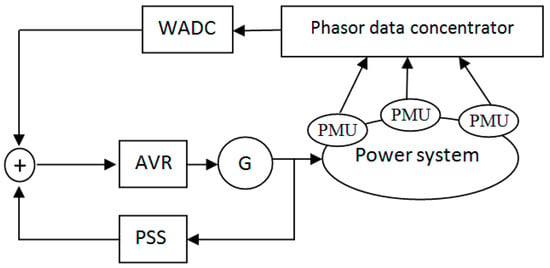
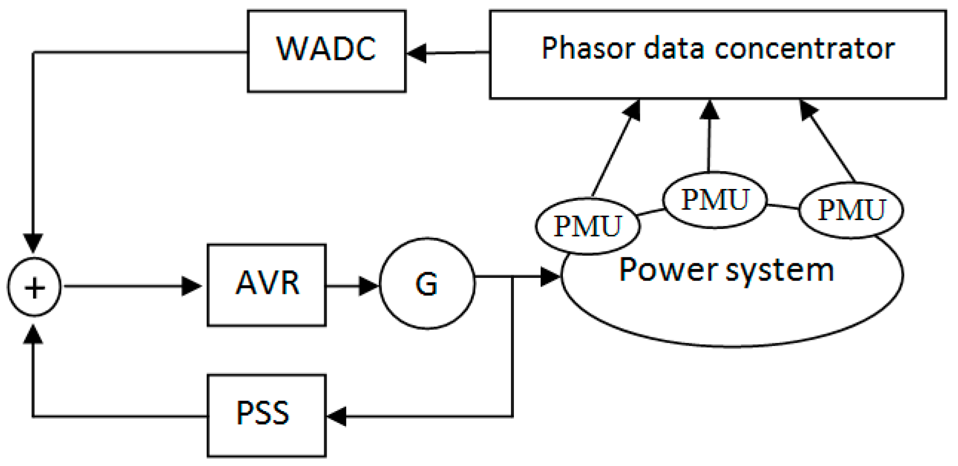
The two-level damping control scheme is a widely adopted strategy for applying WADCs in power systems. This approach enhances system stability by combining the local control provided by conventional PSSs with the broader, system-wide control achieved through WADCs. By integrating both local and wide-area control actions, the two-level scheme is able to damp both local and inter-area oscillations, particularly in large, interconnected grids. Figure 1 illustrates the typical configuration of the two-level control structure. At the local level, PSSs are designed to manage local oscillations by responding to generator-specific signals like rotor speed or power output. At the wide-area level, WADCs utilize remote measurements from PMUs spread across the grid. These measurements help the WADC detect and control inter-area oscillations that local PSSs might not effectively address due to their localized scope. Both controllers send control signals to the generator’s excitation system.
Figure 1.
Typical two-level damping control structure integrating local PSSs and the WADC.
2.2. Input and Output Signal Selection
Effective signal selection is critical to the success of the WADC design. The choice of input and output signals significantly impacts the controller’s ability to damp low-frequency oscillations, particularly inter-area modes, which are more difficult to manage with local controls alone.
2.2.1. Input Signal Selection
The input signals to the WADC are selected based on their observability index, which quantifies how well the dynamics of a particular oscillation mode can be monitored from those signals. These signals are typically obtained from wide-area measurements made possible by PMUs. The most commonly used signals are the speed difference, tie-line active power, generator angle, and voltage and current magnitude and angle. Speed difference between distant generators is often used, as it provides significant sensitivity to inter-area modes, making it an effective input signal [8,9,10].
2.2.2. Output Signal Selection
The output signals are chosen based on their controllability index, which measures how effectively control actions at these locations can influence the system’s oscillatory modes. These output signals are typically injected into the excitation systems (automatic voltage regulators) of generators, modulating their voltage control to achieve desired damping of oscillations. They can also be directed to other power system control devices such as Flexible AC Transmission System (FACTS) devices and High-Voltage Direct Current (HVDC) links. These technologies are highly effective in modulating power flow and voltage, offering additional flexibility for damping inter-area oscillations.
2.2.3. Combining Input and Output
To achieve optimal damping performance, it is essential to consider both input and output selections in conjunction. Geometric measures and residue indices serve as valuable tools for this purpose, combining insights from both observability and controllability into a cohesive analysis of the control loop [19]. These indices facilitate a comprehensive evaluation of how well the selected input signals can monitor oscillation modes and how effectively the output signals can influence those modes, ensuring that the WADC operates efficiently in dampening inter-area oscillations while complementing the actions of local PSSs. Residue analysis is one of the most widely adopted techniques in power system damping control, especially for WADC design. Residue is particularly useful because it simplifies the input/output selection process. The higher the residue value for a given input/output combination, the more effective that combination is at influencing the oscillatory mode. This makes residue analysis a practical and powerful tool for selecting the most suitable signals for WADC design.
3. Mathematical Background
3.1. Linearized Power System Model and Residue-Based Analysis
A power system is inherently nonlinear, but it can typically be linearized around a specific operating point. This linear approximation is particularly useful for analyzing system oscillations. Moreover, linear models provide a foundation for designing control systems that effectively damp these oscillations. The linearized model of the power system is described by the following state-space equation [9]:
where x, u, and y represent the state, input, and output vectors, respectively, while A, B, and C are the state, input, and output matrices. Eigenanalysis of the matrix A yields the eigenvalues λi and their corresponding right and left eigenvectors, ei and vi, respectively. Physically, the right eigenvector indicates the relative activity of the state variables when a particular mode is excited, a concept commonly referred to as the mode shape in the literature. The mode shape provides valuable insights into the participation of individual machines or groups of machines in a specific oscillatory mode. System oscillations are identified from the eigenvalues of the system, and their damping can be enhanced through the design of suitable controllers. The dynamics of the system can be represented by its transfer function, which relates the input and output signals as follows:
where Ri denotes the residue associated with mode λi. The residue encapsulates critical information about the mode’s controllability and observability, enabling effective input and output signal selection. It is mathematically defined as follows:
The controllability of a mode i from a specific input channel jth is determined by , which quantifies how strongly the input can influence the mode. Conversely, the observability of mode i from an output channel jth is given by , indicating how well the mode’s behavior can be monitored through the output.
When a WADC is introduced, its objective is to modify the damping of specific oscillatory modes. The controller’s effect on the system dynamics is captured by the modified characteristic equation:
where H(s) represents the transfer function of the WADC. The interaction between the controller and the system results in a slight shift in the eigenvalue λi, which can be approximated as follows:
This shift directly reflects the ability of the WADC to enhance damping for the targeted oscillatory mode. Residue analysis thus serves as a cornerstone in the design and optimization of damping controllers, providing a quantitative basis for selecting control actions that are both effective and efficient. A WADC is typically implemented as a lead–lag compensator, with its transfer function expressed as follows:
where Tw represents the washout time constant (usually ranging from 5 to 10 s), T1 and T1 are the time constants of the lead–lag compensator, K is a positive gain constant, and m is the number of lead–lag stages, typically set to 2. The design of H(s) is closely linked to the residue Ri associated with the targeted mode λi. The magnitude |Ri| determines the gain K, while the phase angle of the residue provides guidance for phase compensation. The higher the value of |Ri|, the more effective the damping performance, making it essential to select the input signal with the highest observability.
The phase compensation required for mode λi is calculated as follows:
To achieve the desired phase compensation, the time constants T1 and T2 of the lead–lag compensator can be determined using the following relationships [9]:
where fi is the frequency of the ith mode. By fine-tuning these parameters, the WADC can be optimized to achieve robust and reliable damping performance across a range of operating conditions.
3.2. Expected Impact of Local PSSs on Residue Characteristics
Building upon the residue-based framework established above, we now examine how the presence of local PSSs may influence the robustness of these residues across varying operating conditions.
From a control–theoretic perspective, the residue associated with a given input–output pair depends not only on the system eigenvalues, but also on the corresponding left and right eigenvectors, which reflect the modal observability and controllability properties. While local PSSs are primarily designed to improve damping by modifying eigenvalues, their action also alters the closed-loop structure of the excitation system and, consequently, the eigenvectors associated with electromechanical modes. Specifically, the PSS introduces local feedback that alters the dynamic characteristics of the power system, which are mathematically represented in the state matrix A (Equation (1)). This change in system dynamics perturbs both right eigenvector ei (mode shape and observability) and left eigenvector vi (controllability direction).
When a local PSS operates in parallel with a wide-area control loop, it introduces an additional dynamic feedback path that is tuned using local measurements and local operating assumptions. As operating conditions vary, this local feedback can reshape the relative contribution of generator states to inter-area modes, effectively rotating the associated eigenvectors. Because the residue phase angle is sensitive to the relative alignment between input and output modal vectors, even moderate eigenvector reshaping can lead to significant phase angle variations, despite relatively small changes in eigenvalues. This sensitivity arises because the residue phase angle depends on both the observability phase contribution and the controllability phase contribution. The controllability term is directly influenced by excitation system dynamics, which is precisely where the PSS acts.
This effect is expected to be particularly pronounced for inter-area modes, which are spatially distributed by nature and rely on coherent behavior across multiple generators. A locally acting PSS may partially decouple the generator from the global oscillatory pattern, altering the balance between local and wide-area control actions in an operating-point-dependent manner. As a result, the phase compensation required for effective damping by a fixed-structure wide-area controller may vary significantly across operating conditions.
Moreover, since local PSSs are typically designed with phase compensation optimized for local modes (0.8–2.0 Hz), they introduce unintended phase shifts at inter-area mode frequencies (0.2–0.8 Hz) that further contribute to phase angle inconsistency.
The residue-based analytical methodology presented in the following section is designed to systematically quantify this hypothesized effect and to assess its practical significance for wide-area damping control design.
To the best of the authors’ knowledge, the potential impact of local PSSs on the robustness of wide-area feedback signal selection, particularly in terms of residue phase angle variability, has not been explicitly addressed in previous studies, despite the widespread adoption of hierarchical PSS/WADC configurations in practice. The existing literature largely assumes that the parallel operation of local PSSs and wide-area damping controllers is inherently beneficial, without examining its implications on signal robustness under varying operating conditions. The objective of this work is therefore not to provide a complete theoretical treatment of this interaction, but to conduct a first systematic investigation and to verify whether such an effect can indeed occur.
4. Analysis Method
The selection of input and output signals is a critical step in the design of WADCs, as they must provide sufficient observability and controllability of the targeted inter-area oscillation modes. Traditionally, this selection has relied on the magnitude of modal residues, which quantify how strongly a mode can be influenced by a given input/output pair. However, recent studies show that the phase angle of residues is equally important, as it reflects the consistency of phase compensation required by the controller. A residue phase angle that remains stable across varying operating conditions indicates more robust performance, reducing sensitivity to parameter changes and enhancing damping reliability [9,25,26,27]. Building on this concept, the present study introduces a residue-based phase angle analysis methodology to examine whether the inclusion of a local PSS in parallel with a WADC negatively impacts the robustness of input/output signal selection. The aim is not to propose a new WADC structure, but to quantify robustness degradation when PSSs are active.
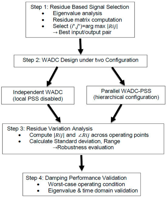
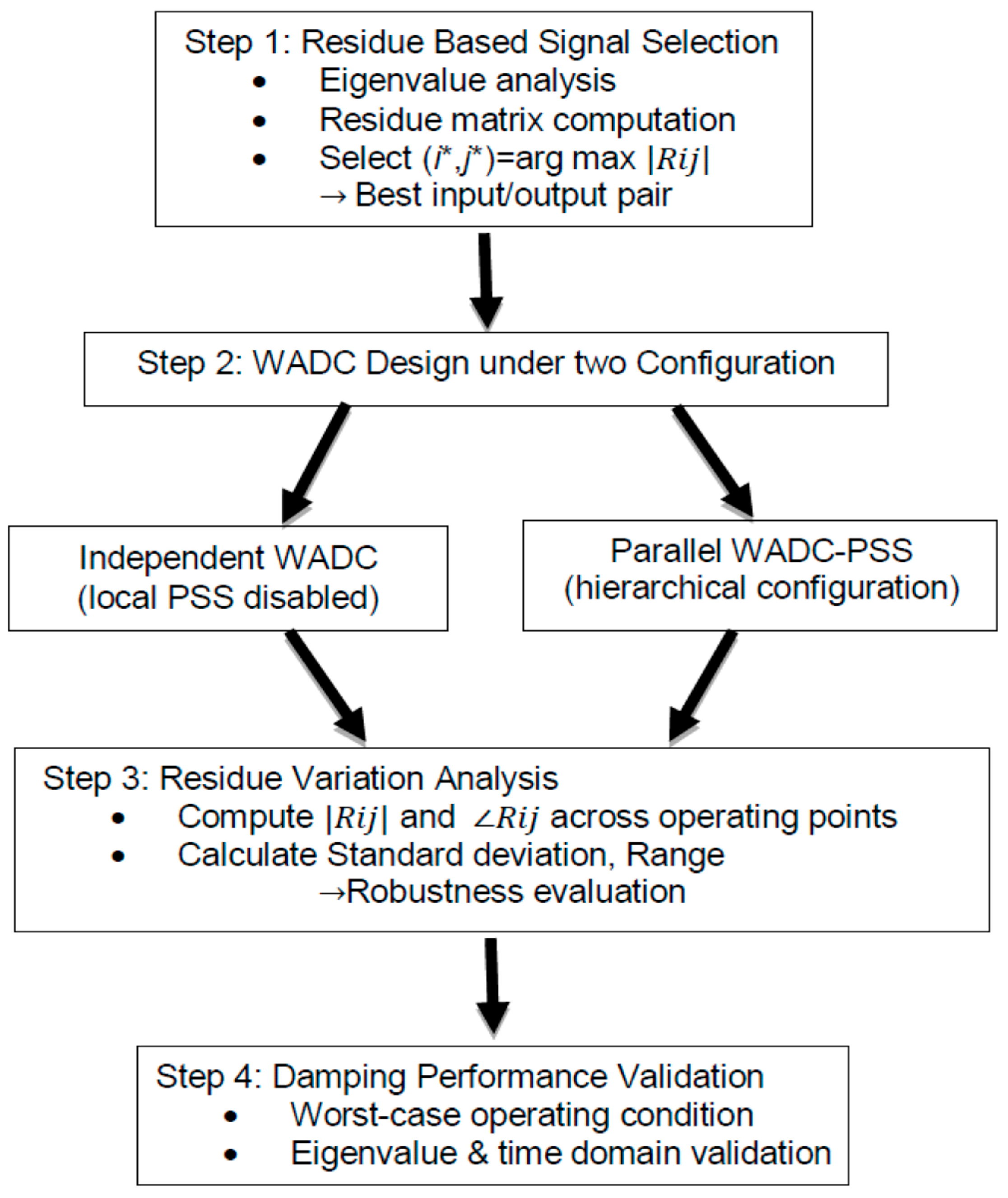
The methodology proceeds through four steps, as illustrated in Figure 2:
Figure 2.
Methodological framework for residue-based input/output robustness analysis.
- Step 1: residue-based signal selection at nominal operating point
For an eigenvalue/eigenvector pair (λk, ek, vk), the modal residue between input i and output j is defined as follows:
where Cj and Bi denote the jth output row and ith input column, respectively.
The signal pair (i∗, j∗) corresponding to the mode λk is selected according to the following:
This ensures that the chosen input/output pair exhibits the strongest controllability and observability for the mode of interest.
- Step 2: WADC design under two control configurations
Using the selected signal pair, we design a WADC at the nominal operating point under two distinct control configurations:
- Independent WADC: The WADC operates independently; local PSSs are disabled.
- Parallel WADC/PSS: The WADC operates in parallel with local PSSs enabled (hierarchical configuration).
To ensure a fair comparison, the same design approach is applied in both cases. The WADC transfer function is realized using the phase-compensation method.
- Step 3: Residue variation analysis across operating points
To evaluate robustness, residues are recalculated across multiple operating conditions. For each configuration, both the magnitude and, with particular emphasis, the phase angle of the selected residue are monitored.
The statistical variation of the phase angle across operating points is quantified using the following:
- Standard deviation:
- Range:
For the residue magnitude, variability across operating points is assessed using the following:
- Standard deviation:
- Range:where N is the total number of operating points, μ = 1,2,…,N denotes the operating point index, θij(μ) represents the residue phase angle corresponding to input i, output j, at operating point μ, and is the mean residue phase angle across all N operating points.Smaller σij and ρij indicate more robust signal selection.
- Step 4: Damping performance validation under worst-case conditions
Finally, closed-loop simulations are performed under the worst-case operating conditions, identified from Step 3 as those exhibiting the largest phase angle deviation. The damping ratios of the inter-area modes are computed from eigenvalue analysis and validated via time-domain simulations. This step verifies whether the presence of a local PSS compromises the robustness and effectiveness of the WADC.
It is worth noting that the residue-based robustness metric is not intended to replace comprehensive controller robustness analyses, but is particularly suited to the signal selection stage of wide-area damping control design, which precedes controller tuning. In fixed-structure WADCs based on lead–lag compensation, robust damping critically depends on consistent phase alignment between the control action and the targeted oscillatory mode. The residue phase angle directly determines the required phase compensation (Equation (7)), and its variability across operating points provides a focused, mode-specific indicator of robustness degradation.
Alternative robustness and signal-evaluation measures have been reported in the literature, including joint geometric measures, singular value-based metrics [8,18,19], and advanced robust control frameworks such as H∞ and μ-synthesis. These approaches are valuable for assessing multivariable interactions, structural limitations, or stability margins under uncertainty, but they typically require a fixed controller structure, higher-order models, or extensive uncertainty descriptions, making them more suitable for later controller synthesis and validation stages.
In contrast, residue-based metrics, which provide a direct scalar link to damping effectiveness through the eigenvalue shift approximation (Equation (5)), are computationally efficient and have been widely validated for wide-area damping signal selection [9,25,26,27]. For the purpose of this study, assessing robustness degradation of wide-area feedback signals under independent and parallel PSS/WADC configurations, the residue phase-based metric is therefore sufficient and appropriate.
5. Application to Test Systems
To rigorously evaluate the impact of local PSSs on WADC robustness, the proposed methodology is applied to two benchmark test systems: the four-machine two-area system and a simplified model of the Hydro–Québec system. These systems provide simplified yet representative models of large interconnected power networks. This application enables a systematic quantification of residue phase angle sensitivity to changes in operating conditions and facilitates an evaluation of whether the conventional hierarchical WADC/PSS structure may inadvertently reduce the effectiveness or consistency of wide-area damping control.
5.1. Four-Machine, Two-Area System
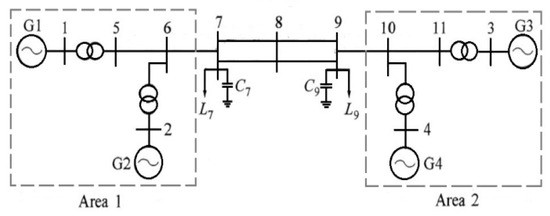
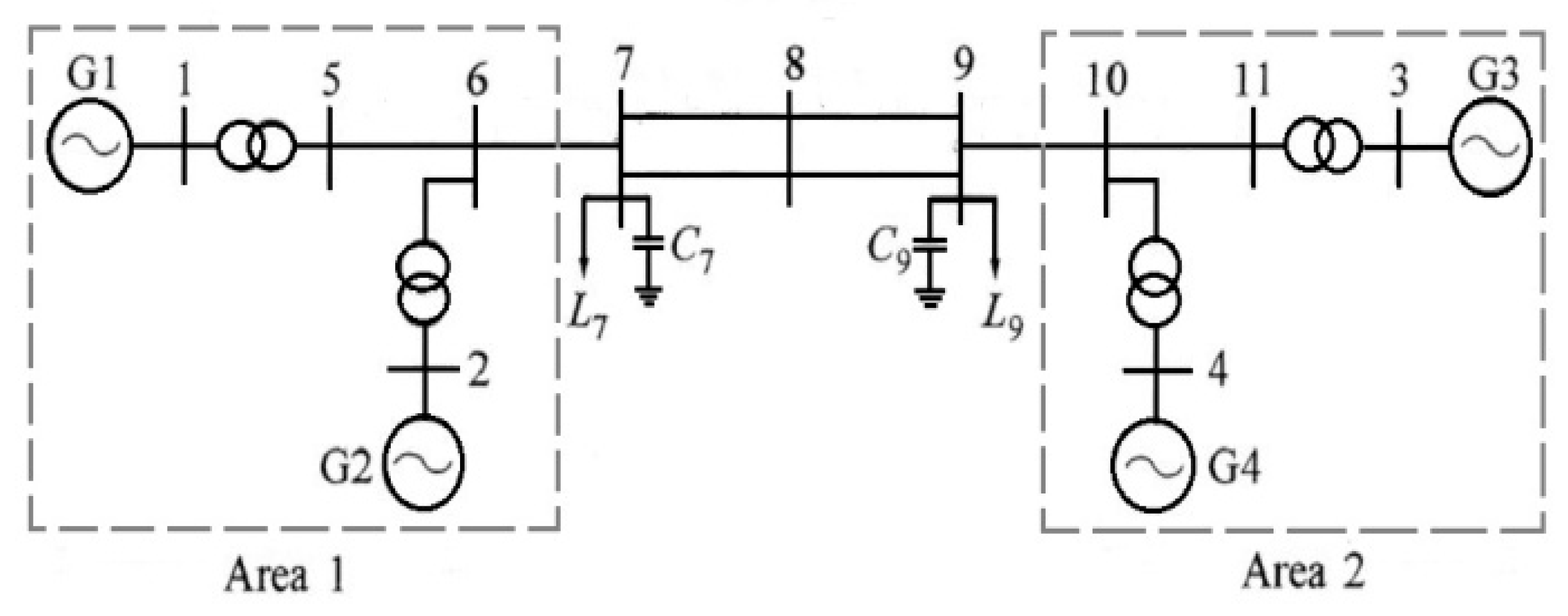
First, the analysis is conducted on the well-known four-machine, two-area system depicted in Figure 3. Further details of the system can be found in [29]. In this system, all generators are equipped with fast static exciters and governors. The system operates with Area 1 exporting 413 MW to Area 2. The model is implemented in MATLAB/Simulink (version 2015a). Small signal analysis reveals that the system exhibits three electromechanical modes, as shown in Table 1. Notably, the system features an unstable inter-area mode at 0.64 Hz, where Area 1 oscillates against Area 2.
Figure 3.
Schematic of the four-machine, two-area system.
Table 1.
Electromechanical modes of the four-machine, two-area system.
An original PSS, as described in [29], is installed on generator G2. However, this PSS does not provide sufficient damping improvement for the inter-area mode, which remains unstable with a damping ratio of −0.4%. This limitation arises because the inter-area mode is not adequately observable in the locally available signals. As highlighted in several studies, achieving effective damping for this critical mode necessitates the implementation of a WADC [9]. We assume that the WADC will be applied in parallel with the local PSS at G2. To investigate the impact of the local PSS, we analyze residue metrics under two configurations:
- When the WADC operates in parallel with the local PSS at G2.
- When the WADC operates independently without the local PSS at G1.
For further investigation, we also analyze the case where the WADC is applied independently at G4, as G4 provides high controllability of the inter-area mode among the four generators.
After analyzing observability indices for various signals, those with high observability of the inter-area mode are classified in Table 2. Among them, the speed difference signal Δω13 (i.e., Δω1–Δω3) offers the best observability of the inter-area mode and is chosen as the primary input to the WADC. For comparative purposes, the speed difference signals Δω23 and Δω14 are also chosen.
Table 2.
Classification of signals based on inter-area mode observability.
The WADCs designed for the selected input/output signal pairs are detailed in Table 3. The residue phase compensation method described in Section 3 is employed for controller design. Table 3 summarizes the damping performance of each WADC for the inter-area mode under nominal operating conditions. It is important to note that a local PSS is installed at G2 during this analysis.
Table 3.
Damping performance of WADCs for selected input/output signal pairs under nominal conditions.
It is worth emphasizing that the WADC designs presented in this study are intended solely to validate the effectiveness of the selected input/output signals and to support our robustness analysis. In practical wide-area control implementations, factors such as communication time delays can affect WADC performance and must be taken into account during the controller design and tuning stage. However, our study does not aim to optimize or implement the controller itself, but rather to evaluate the robustness of signal selection under different configurations. The proposed methodology is thus focused on identifying signal pairs that remain effective across a broad range of operating conditions, regardless of the eventual control design strategy.
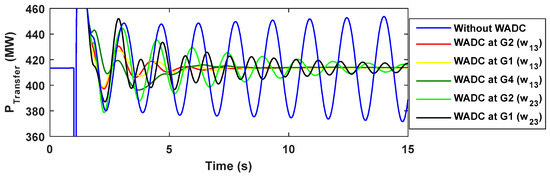
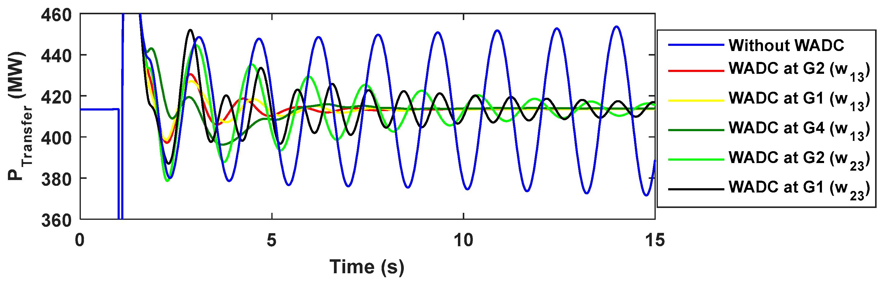
To evaluate the performance of the five WADCs, a three-phase fault was applied at 1 s at the midpoint of the tie-lines (Bus 8 in Figure 3) for duration of 100 ms. The fault was cleared without causing a tie-line outage. Figure 4 shows the response of the power transfer between the two areas. It is evident that the WADCs improve the damping of the inter-area mode. However, the damping provided by the WADC at G2 with Δω23 as input is less effective compared to the other WADCs. The oscillations observed in the figure when the WADC is applied at G1 with Δω23 as input are not associated with the inter-area mode but rather with the local mode in Area 1. The damping of this local mode is deteriorated due to the application of the WADC.
Figure 4.
Power transfer response following a three-phase fault with a local PSS installed at G2.
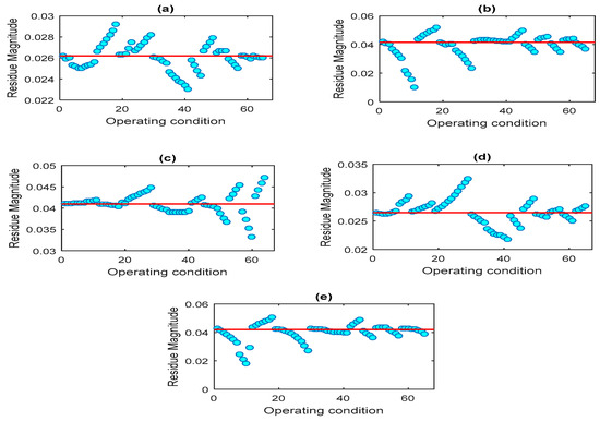
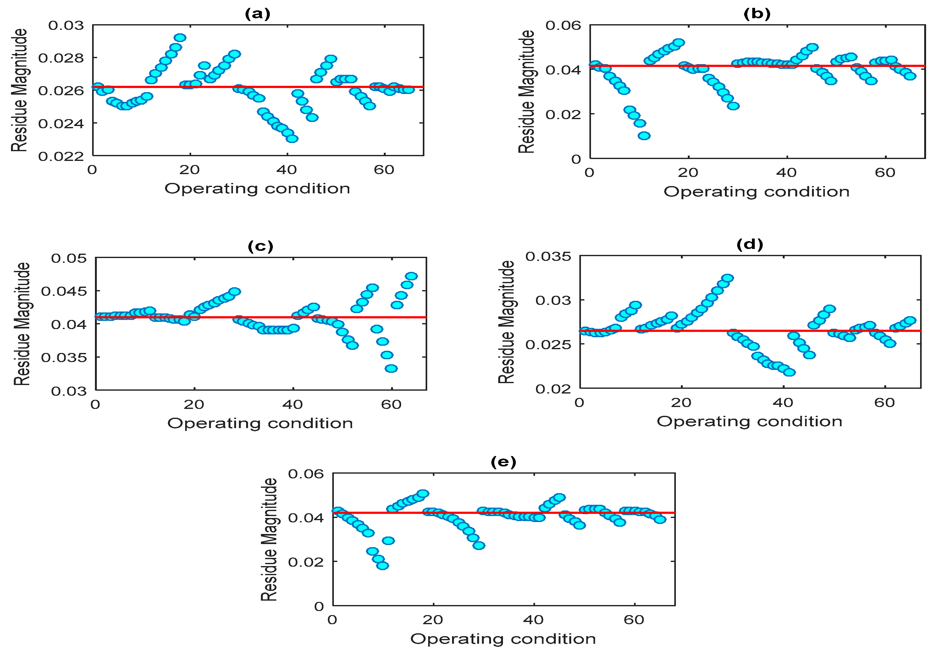
To comprehensively assess the robustness of the selected input/output signals, we examine variations in both residue magnitude and phase angle across a wide range of power system operating conditions. In this study, various system conditions are generated by varying generator power outputs, load demands, and N-1 outage contingencies of lines and generators. Each generator’s output and load demand are varied within a range of ±30% (in 50 MW steps) from their nominal operating values. Generator outages are modeled by setting their output to zero. This process results in a total of 65 operating conditions.
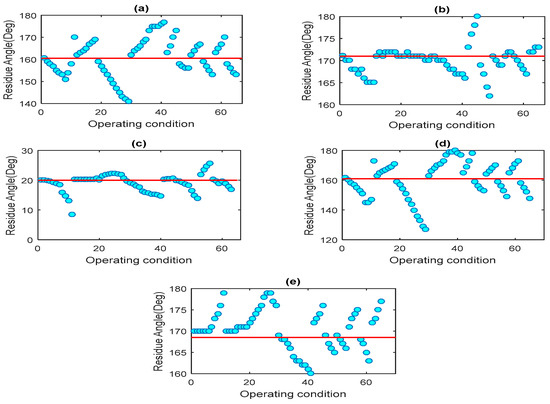
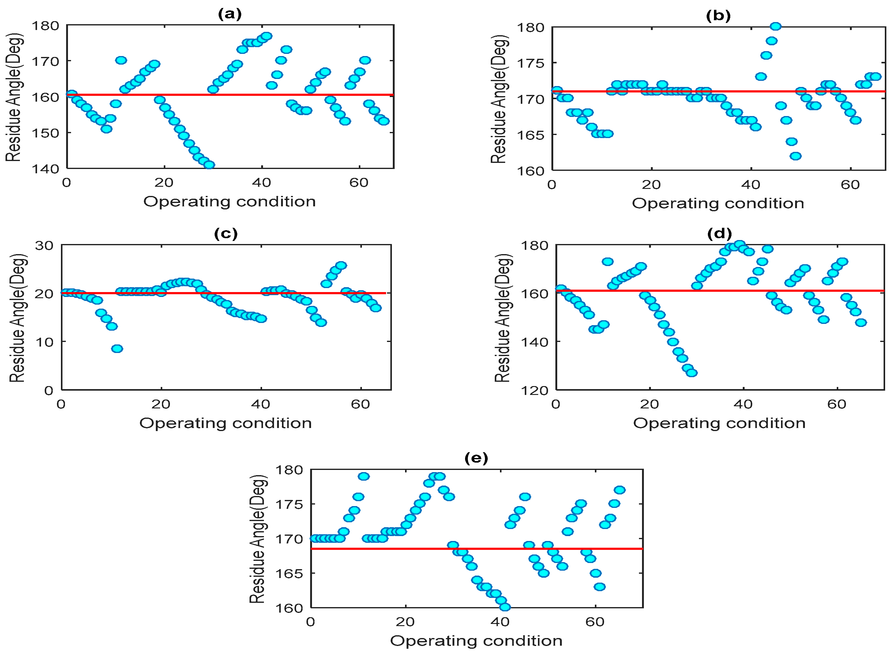
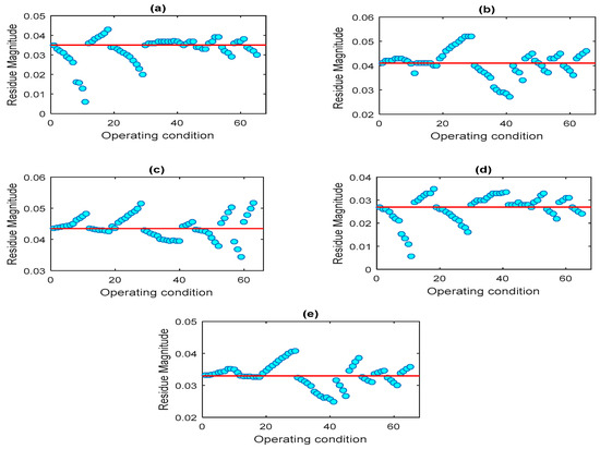
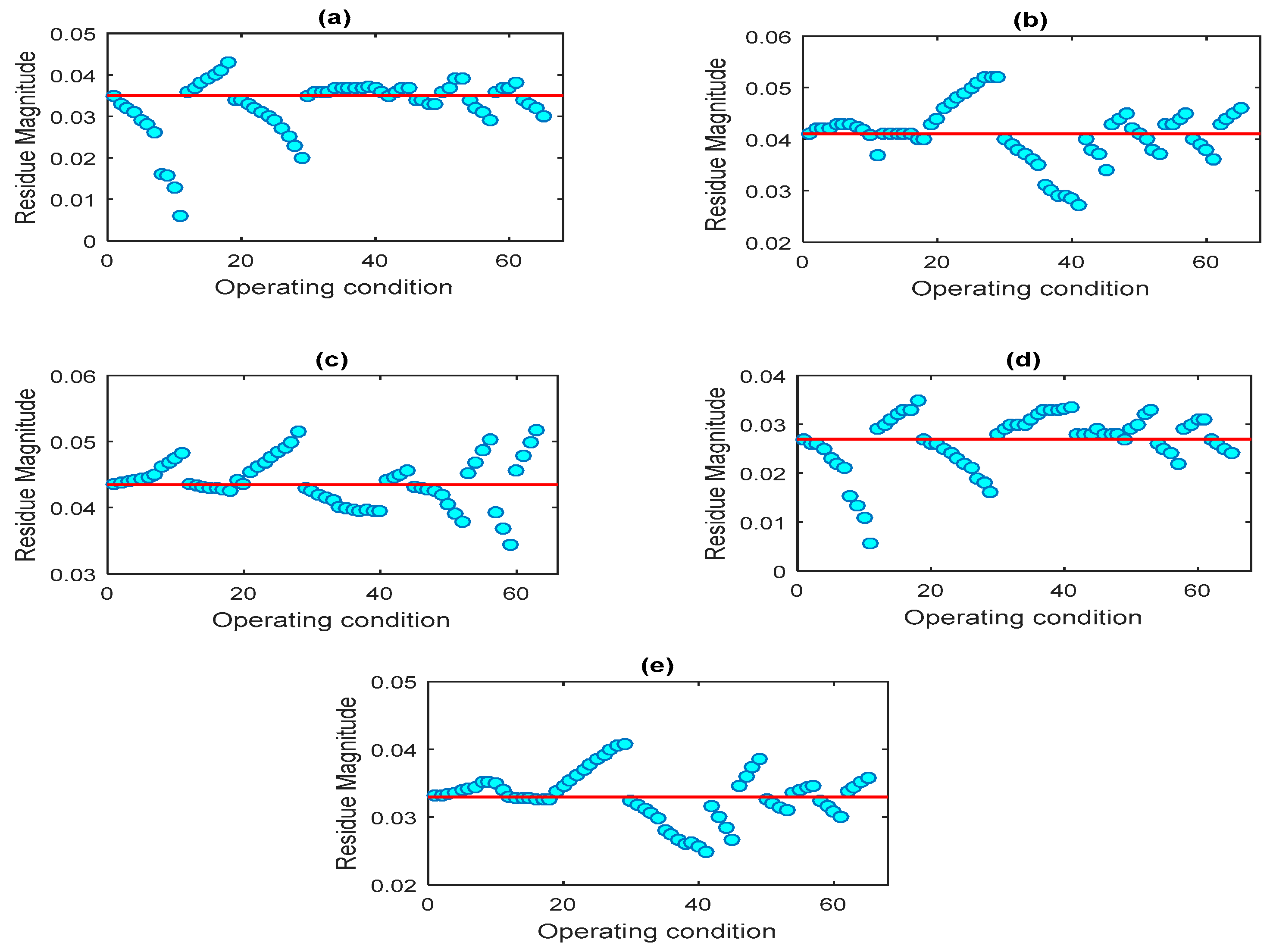
Figure 5 and Figure 6 illustrate the variation in the angle and magnitude of the residue for the input/output signal pairs across all operating conditions. The figures show that the variation in the absolute value and angle of the residue ishigh for G2 (with a local PSS) for both input signals Δω13 and Δω23. Contrary, fewervariations are shown for both signals for G1 and G4 (without a local PSS).
Figure 5.
Variation of residue phase angle across operating conditions with a local PSS installed at G2. (a) input: Δω13, output: G2. (b) input: Δω13, output: G1. (c) input: Δω13, output: G4. (d) input: Δω23, output: G2. (e) input: Δω23, output: G1.
Figure 6.
Variation of residue magnitude across operating conditions with a local PSS installed at G2. (a) input: Δω13, output: G2. (b) input: Δω13, output: G1. (c) input: Δω13, output: G4. (d) input: Δω23, output: G2. (e) input: Δω23, output: G1.
When the phase angle of the selected input/output signals deviates significantly from its nominal value across operating conditions, the controller may no longer provide the intended damping torque in proper phase alignment with the oscillation mode. The effectiveness of lead–lag compensators designed using (7) relies on accurate phase compensation; deviations between the actual residue phase angle and the design assumption cause misalignment between the control action and the targeted oscillation, progressively reducing damping effectiveness. In residue-based controller design, a 10° phase angle variation threshold has been widely adopted as a conservative, practical benchmark for identifying potential robustness concerns. References [9,25] applied this criterion in the context of PSSs and wide-area damping control, respectively, showing that maintaining residue phase angle consistency within approximately ±10° across operating conditions tends to correlate with more robust damping performance. This threshold should not be interpreted as a sharp boundary beyond which controllers necessarily fail, but rather as a screening indicator: signal pairs exhibiting phase angle variations well within this range are likely to maintain consistent performance, while those approaching or exceeding 10° warrant closer examination through detailed analysis. The actual sensitivity to phase angle variations depends on multiple factors including controller structure, gain settings, and the specific characteristics of the oscillation mode. Therefore, we adopt the 10° threshold in this study as a conservative guideline for preliminary robustness assessment in fixed-structure WADCs.
The analysis reveals that the residue phase angle at G2 exceeds the nominal value by more than 10° in several operating conditions, indicating that the WADC designed at the nominal point may not maintain effective damping in those scenarios. Specifically:
- For the signal Δω13, the residue angle exceeds the 10° threshold in 16 operating conditions, with a maximum deviation of 19° occurring when the load demand at bus 9 is reduced by 30%.
- For Δω23, the phase angle exceeds the threshold in 28 operating conditions, with a maximum deviation of 35°, also under a 30% load reduction at bus 9.
In contrast, when the WADC is operated independently (i.e., without the local PSS at G1):
- For Δω13, the residue phase angle remains within ±10° across all operating conditions, indicating high robustness of the controller.
- For Δω23, the 10° threshold is exceeded in only one operating condition, reaching exactly 10° when the load at bus 9 is increased by 30%.
When the WADC is configured to operate independently at G4, the 10° threshold is exceeded only once for Δω13, with a maximum deviation of 12° under a 30% load reduction at bus 7.
This initial analysis shows that the presence of local PSSs in parallel may introduce significant variability in the residue phase angle, potentially compromising the robustness of wide-area damping control. However, given the complexity of the data, visual inspection alone is insufficient to capture the full extent of variation. To address this, statistical indices such as the range and standard deviation are computed, providing a more comprehensive and quantitative assessment. These indices, presented in Table 4, are used to evaluate variations in residue magnitude and phase angle and to assess the robustness of the designed WADCs. The results clearly reveal substantial phase angle variations for the WADC configured at G2, pointing to reduced robustness in that configuration.
Table 4.
Statistical analysis of residue variations with a local PSS installed at G2.
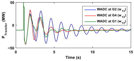
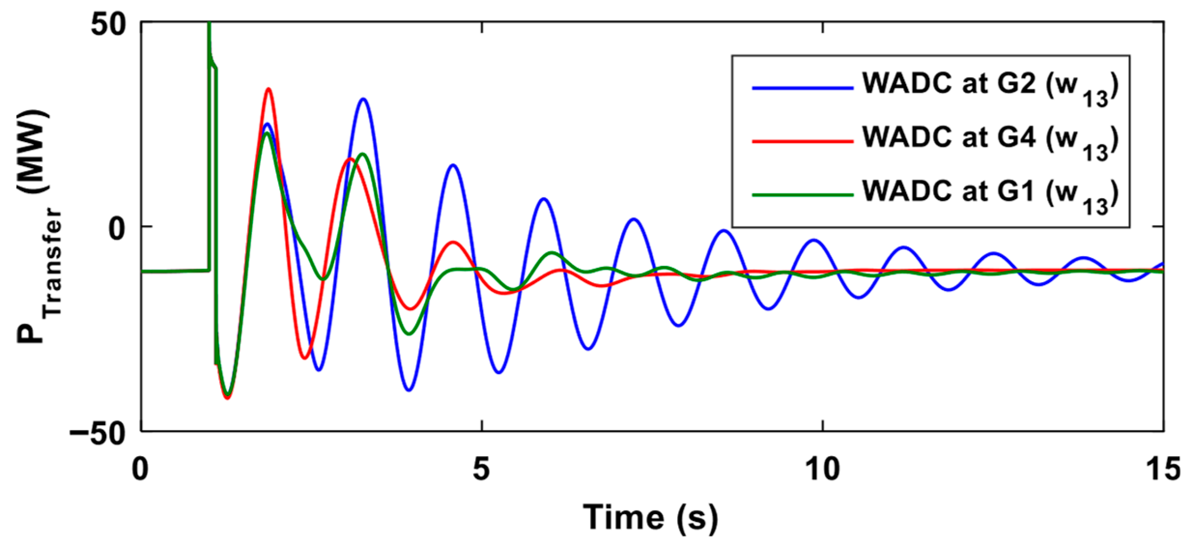
These results demonstrate that applying the WADC independently, without the local PSS in parallel, results in high robustness of the controller, leading to superior damping performance across a wide range of operating conditions. Conversely, when the WADC is applied in parallel with the local PSS at G2, the controller exhibits low robustness, potentially becoming ineffective under certain operating conditions. For instance, when the load demand at bus 9 is reduced by 30%, the WADC at G2 with Δω13 as input provides a damping ratio of only 4.77% for the inter-area mode, compared to 15.38% under nominal conditions. In contrast, the WADC at G1 continues to deliver satisfactory damping (greater than 13%) for the same operating condition with both input signals Δω13 and Δω23. Furthermore, the WADC at G4 with Δω13 as input maintains excellent performance, providing a damping ratio of 18.66% under the same scenario. This is further validated in Figure 7, which shows the response to a three-phase fault applied at 1 s at the midpoint of the tie-lines for 100 ms duration. At this operating point, power transfer shifts from Area 1 to Area 2, with approximately 11 MW transferred, as shown in the figure.
Figure 7.
System response to a three-phase fault with a 30% load reduction at Bus 9.
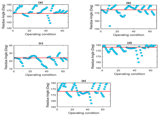
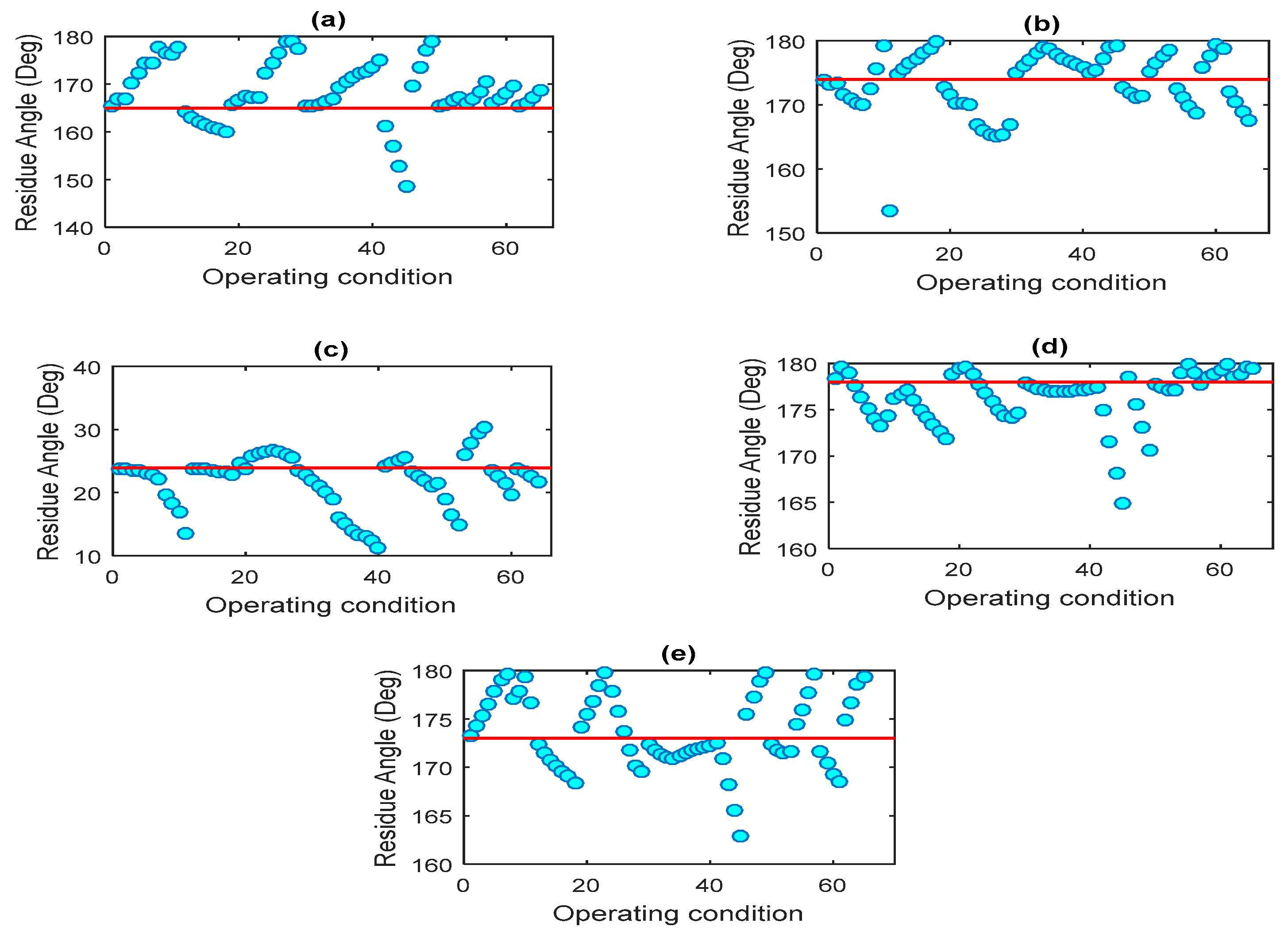
We now remove the local PSS from G2 and install it at G1. Figure 8 and Figure 9 illustrate the variation in the angle and magnitude of the residue for signals Δω13 and Δω23 across all operating conditions. The figures reveal that the variation in the angle of the residue is higher at G1 (with the local PSS) for signal Δω13 compared to G2 and G4 (without the local PSS).
Figure 8.
Variation of residue phase angle across operating conditions with a local PSS installed at G1. (a) input: Δω13, output: G1. (b) input: Δω13, output: G2. (c) input: Δω13, output: G4. (d) input: Δω23, output: G1. (e) input: Δω23, output: G2.
Figure 9.
Variation of residue magnitude across operating conditions with a local PSS installed at G1. (a) input: Δω13, output: G1. (b) input: Δω13, output: G2. (c) input: Δω13, output: G4. (d) input: Δω23, output: G1. (e) input: Δω23, output: G2.
As we can see in Table 5, the standard deviation of the residue angle for signal Δω13 at G2 decreases to 4.80 from 8.54 when the local PSS is removed from G2. Similarly, the standard deviation for signal Δω23 at G2 drops significantly from 12.43 (with the local PSS) to 3.81 (without the local PSS). These results confirm that the high variation in the residue angle observed at G2 in the initial case is primarily due to the local PSS operating in parallel with the wide area loop. However, in the second case, where the local PSS is relocated to G1, the variation in the residue angle for Δω23 at G1 remains relatively low, even with the PSS operating in parallel. This observation suggests that the impact of the local PSS on residue variability may depend on the generator location and system dynamics, prompting further investigation. Accordingly, we proceed by removing the local PSS from G1 and installing it in Area 2, starting with G3.
Table 5.
Statistical analysis of residue variations with a local PSS installed at G1.
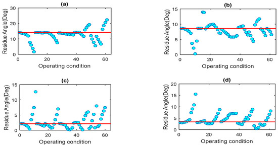
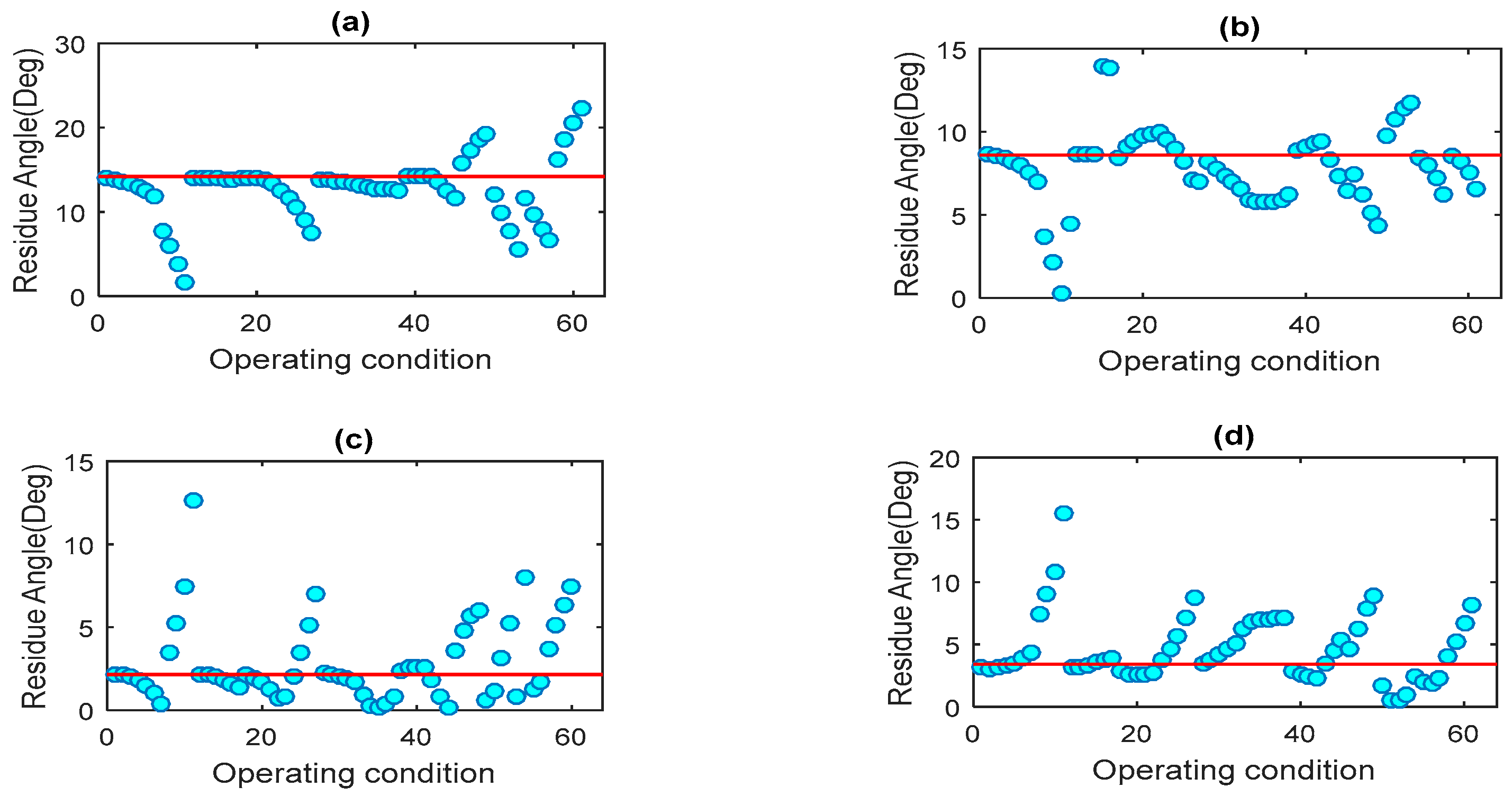
Figure 10 and Figure 11 present the variation in the angle and magnitude of the residue for signals Δω13 and Δω14 across all operating conditions. The results indicate that the variation in the residue angle is smaller at G4 (without the local PSS) for both signals compared to G3 (with the local PSS). Similarly, when the local PSS is installed at G4 (Figure 12 and Figure 13), the variation in the residue angle shown in Figure 12 becomes less at G3 (without the local PSS) for both signals Δω13 and Δω14 compared to G4 (with the local PSS).
Figure 10.
Variation of residue phase angle across operating conditions with a local PSS installed at G3. (a) input: Δω13, output: G3. (b) input: Δω13, output: G4. (c) input: Δω14, output: G3. (d) input: Δω14, output: G4.
Figure 11.
Variation of residue magnitude across operating conditions with a local PSS installed at G3. (a) input: Δω13, output: G3. (b) input: Δω13, output: G4. (c) input: Δω14, output: G3. (d) input: Δω14, output: G4.
Figure 12.
Variation of residue phase angle across operating conditions with a local PSS installed at G4. (a) input: Δω13, output: G4. (b) input: Δω13, output: G3. (c) input: Δω14, output: G4. (d) input: Δω14, output: G3.
Figure 13.
Variation of residue magnitude across operating conditions with a local PSS installed at G4. (a) input: Δω13, output: G4. (b) input: Δω13, output: G3. (c) input: Δω14, output: G4. (d) input: Δω14, output: G3.
Quantitatively, as shown in Table 6, the standard deviation of the residue phase angle for the signal Δω14 at G3 decreases from 8.05 to 2.91 when the local PSS is removed. Similarly, for G4 (Table 7), the standard deviation of the residue angle for Δω13 increases from 2.31 (without the local PSS) to 6.22 when the local PSS is installed.
Table 6.
Statistical analysis of residue variations with a local PSS installed at G3.
Table 7.
Statistical analysis of residue variations with a local PSS installed at G4.
These findings further emphasize that applying the WADC independently, without the local PSS operating in parallel, enhances the controller’s robustness and ensures superior damping performance across a wide range of operating conditions.
To provide a compact synthesis of the numerical results obtained for the Kundur four-machine two-area system, Table 8 summarizes the residue phase robustness characteristics for the two control configurations considered. The table aggregates the typical dispersion and worst-case range of residue phase angle variations observed across all operating conditions and relates them to their impact on inter-area mode damping performance. This summary enables a direct comparison between the independent WADC and the conventional parallel PSS/WADC configurations, highlighting the robustness differences identified through the detailed residue-based analysis.
Table 8.
Consolidated robustness comparison for the four-machine two-area system.
5.2. Hydro–Québec System
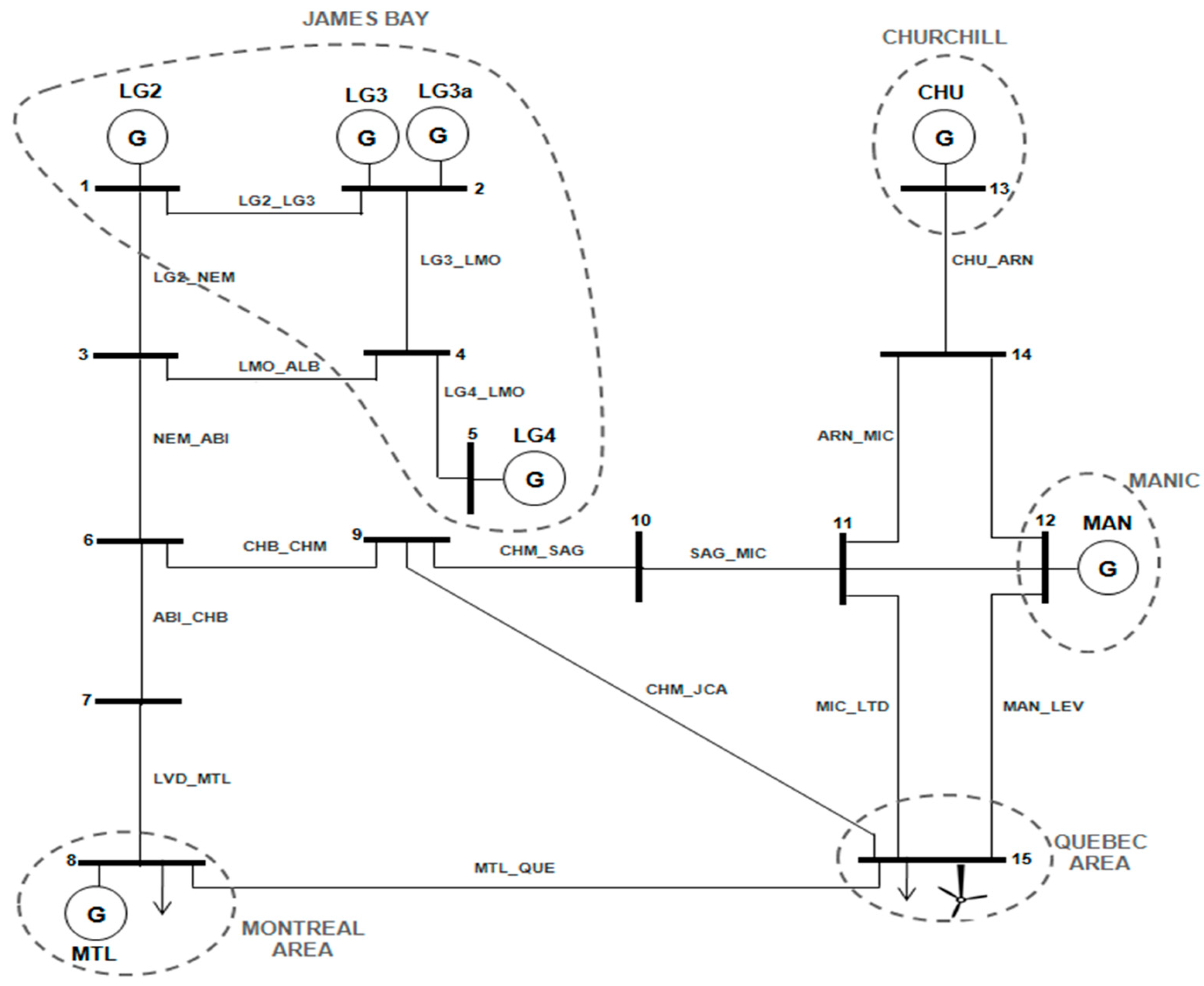
To further investigate the impact of local PSSs on the robustness of input/output signal selection for WADCs, the analysis is extended to a simplified model of the Hydro–Québec system, as shown in Figure 14. This model, implemented in MATLAB/Simulink, consists of three interconnected areas: the northwest region (James Bay) with four generators, the northeast region (Churchill and Manic) with two generators, and the southern region near the primary load centers (Montreal and Quebec) with a single generator. A 9 MW wind farm using an asynchronous generator is also connected near the Quebec load. All generators are equipped with static exciters and standard HYGOV turbine governors. The model has been widely used in the literature [30,31,32], and its dynamic characteristics have been well validated. The system exhibits several electromechanical oscillation modes, including a dominant inter-area mode at 0.98 Hz between the northwest and northeast regions. In the absence of any PSSs, this mode is unstable, with a damping ratio of −1.22%. This makes the model particularly suitable for evaluating how the presence of a local PSS affects the robustness of WADC input/output signal selection across varying operating conditions.
Figure 14.
Simplified model of the Hydro–Québec system.
Table 9 presents the observability and controllability indices, along with the absolute residue values associated with the critical mode at the main generators, using speed deviation as the output signal. This analysis helps identify the most effective locations for control implementation.
Table 9.
Observability, controllability indices, and absolute residue values for the critical mode.
It is evident from Table 8 that Churchill and LG2 are suitable locations for PSS installation, as they exhibit strong observability and controllability with respect to the targeted mode.
A local PSS is installed at Churchill, providing a damping ratio of 7.87% for the critical mode. To enhance the damping further, a WADC is introduced. To evaluate the impact of the local PSS on WADC performance, residue-based metrics are analyzed under two configurations:
- When the WADC operates in parallel with the local PSS at Churchill.
- When the WADC operates independently, without the local PSS, and is implemented at LG2.
After analyzing observability indices for various signals, the speed difference signal between LG2 and Churchill offers the best observability of the inter-area mode and is chosen as the input to the WADC. The residue phase compensation method outlined in Section 3 is used for the controller design. The transfer function of the WADC operating in parallel with the local PSS at Churchill is given by
This configuration provides a damping of 30.57% for the mode of interest.
On the other hand, the transfer function of the WADC operating independently at LG2 is given by
This independent configuration achieves a slightly higher damping ratio of 32.58%.
Both WADCs achieve high damping for the targeted inter-area mode, as they are explicitly designed to enhance this particular mode. However, in practical applications, the controller gains can be adjusted to prevent the WADC from inadvertently influencing other modes in the system. In this study, the primary purpose of designing the WADCs is to validate the effectiveness of the selected input/output signal pairs for wide-area control implementation. The controller design itself is not the focus of the analysis. Instead, our evaluation is centered on the variation of residue magnitude and phase angle across a wide range of operating conditions, which serves as the basis for assessing the robustness of the selected signals.
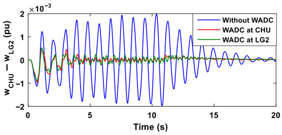
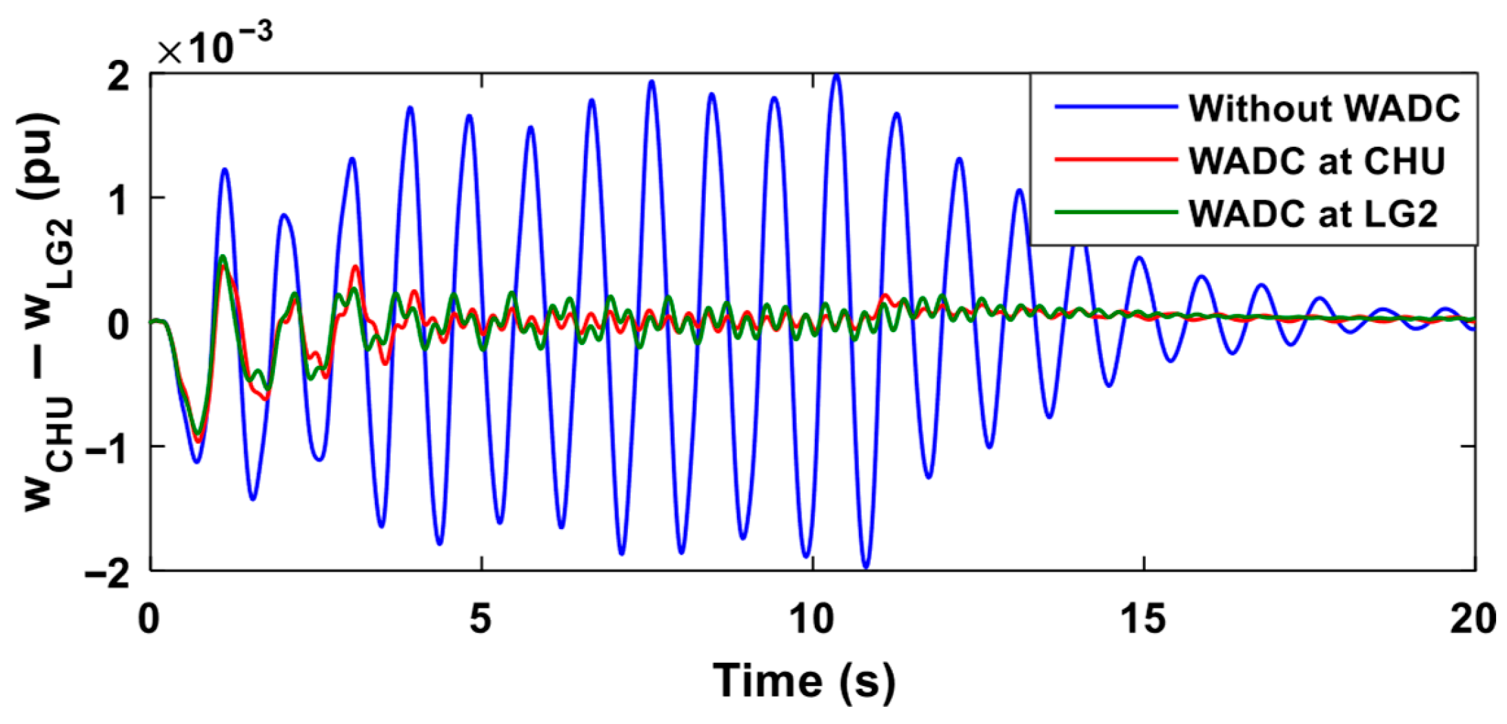
To evaluate the performance of the two WADCs, a three-phase fault was applied near Montreal (Bus 8 in Figure 14) with a duration of 100 ms. The fault was cleared without any tie-line outage. Figure 15 shows the speed deviation between Churchill and LG2 following the disturbance. The results demonstrate that both WADCs significantly improve the damping of the inter-area oscillation mode, thereby validating the findings from the eigenvalue analysis.
Figure 15.
Speed deviation between Churchill and LG2 following a three-phase fault near Montreal.
To thoroughly assess the robustness of the controllers, we analyze variations in both residue magnitude and phase angle across a wide range of power system operating conditions. In this study, various system scenarios are created by adjusting generator power outputs, load demands, and N-1 contingency outages of lines and generators. Each generator’s output is varied within ±40% of its nominal value, in steps of 200 MW. The Montreal load is adjusted by ±40% in 500 MW increments, while the Quebec load is varied by ±40% in 300 MW increments. Generator outages are modeled by setting the corresponding generator output to zero. This process results in a total of 100 distinct operating conditions for robustness evaluation.
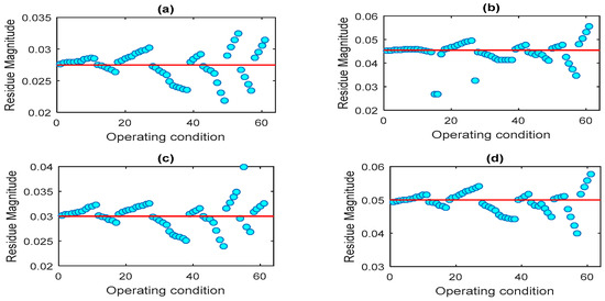
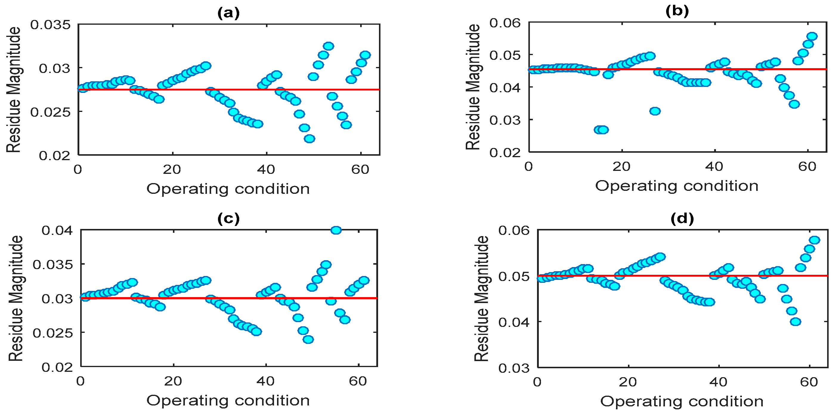
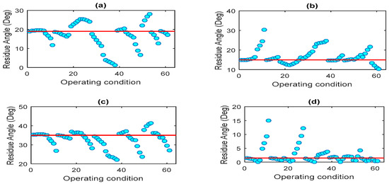
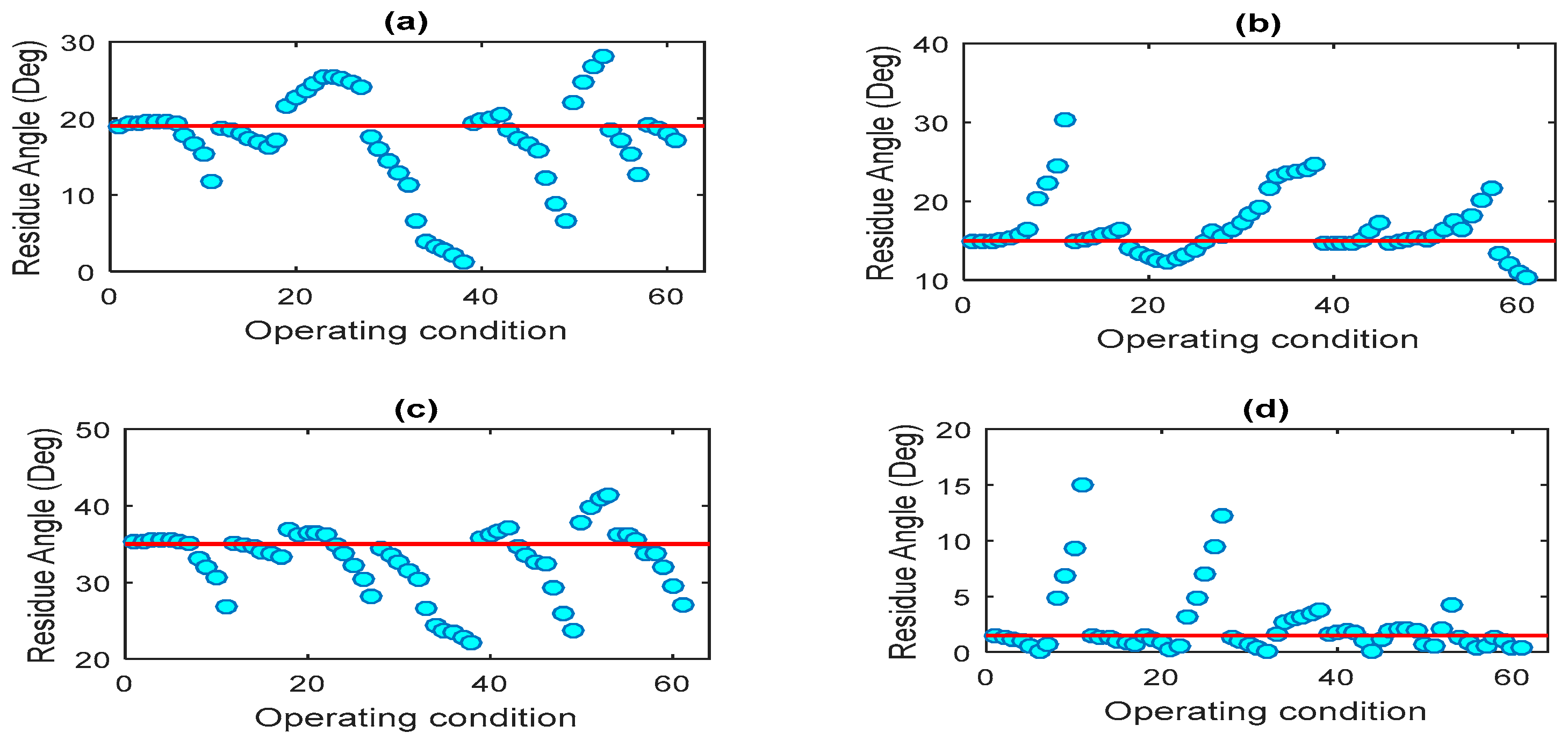
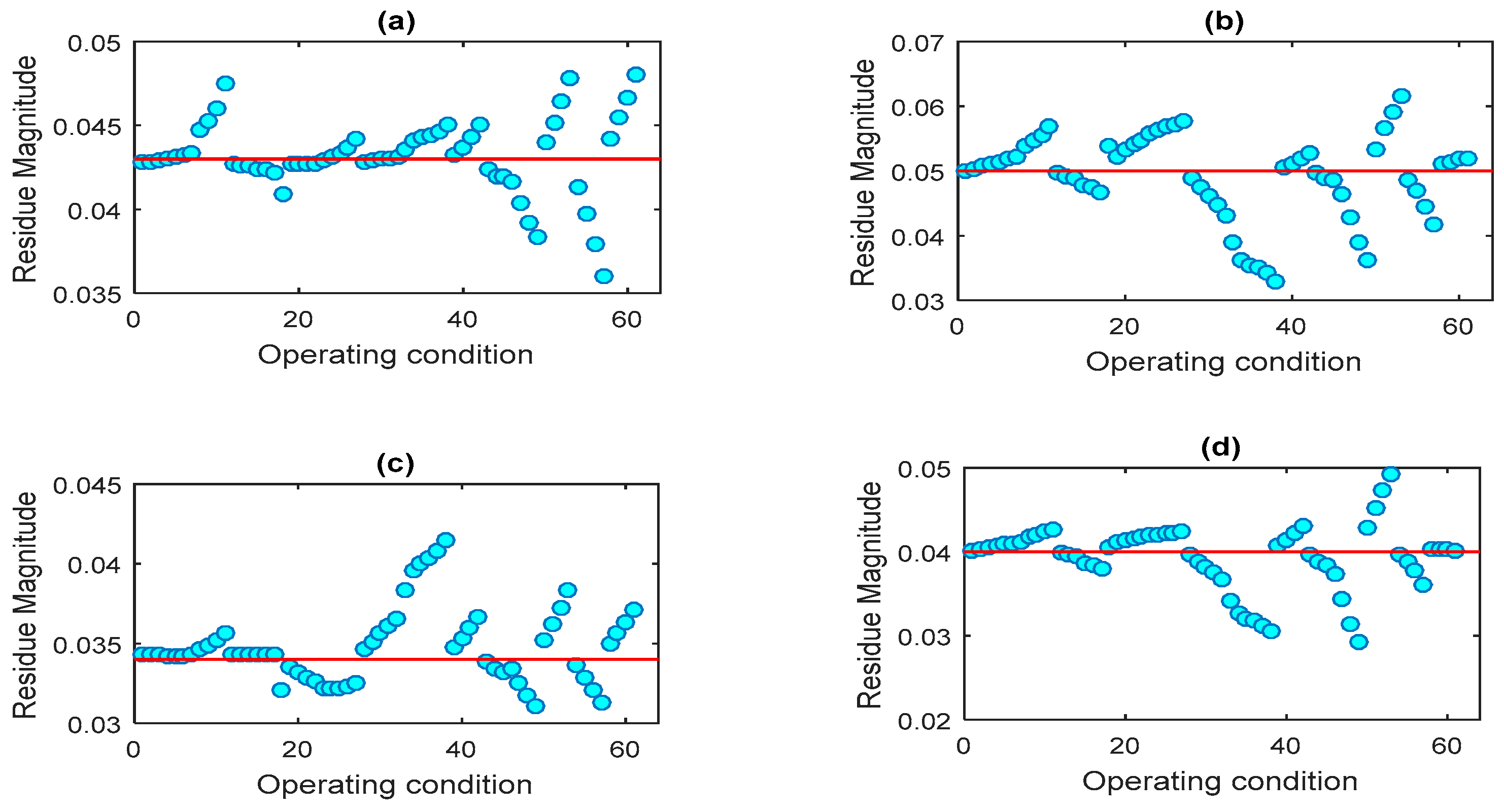
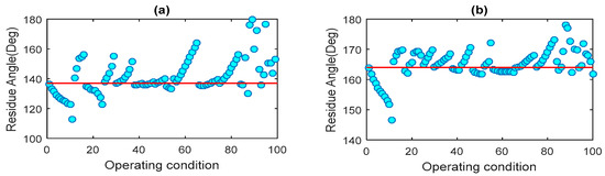
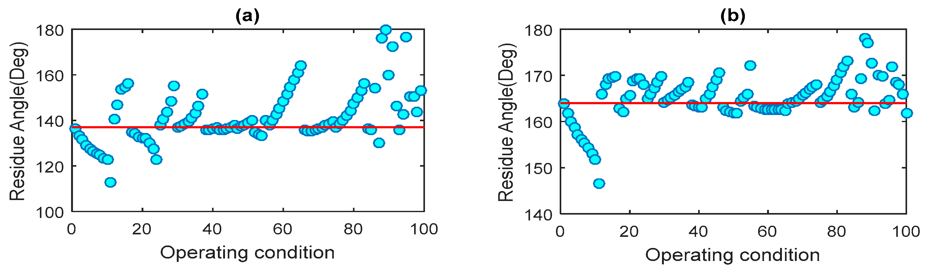
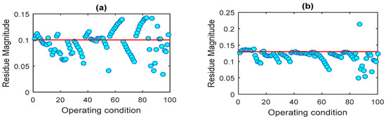
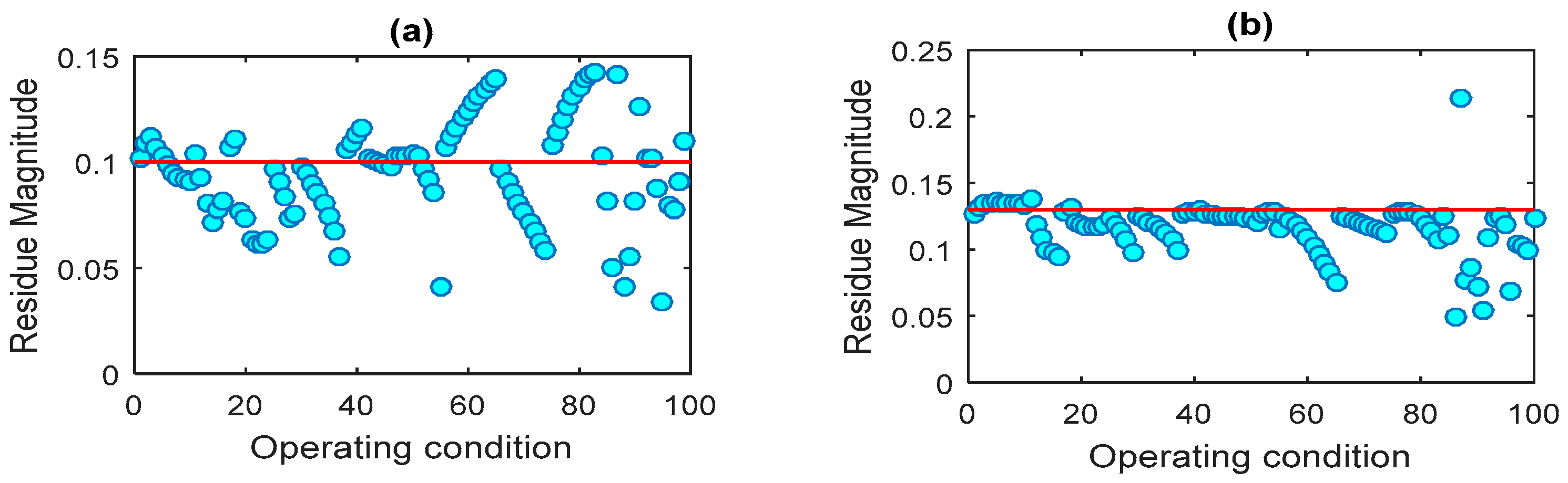
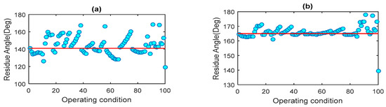
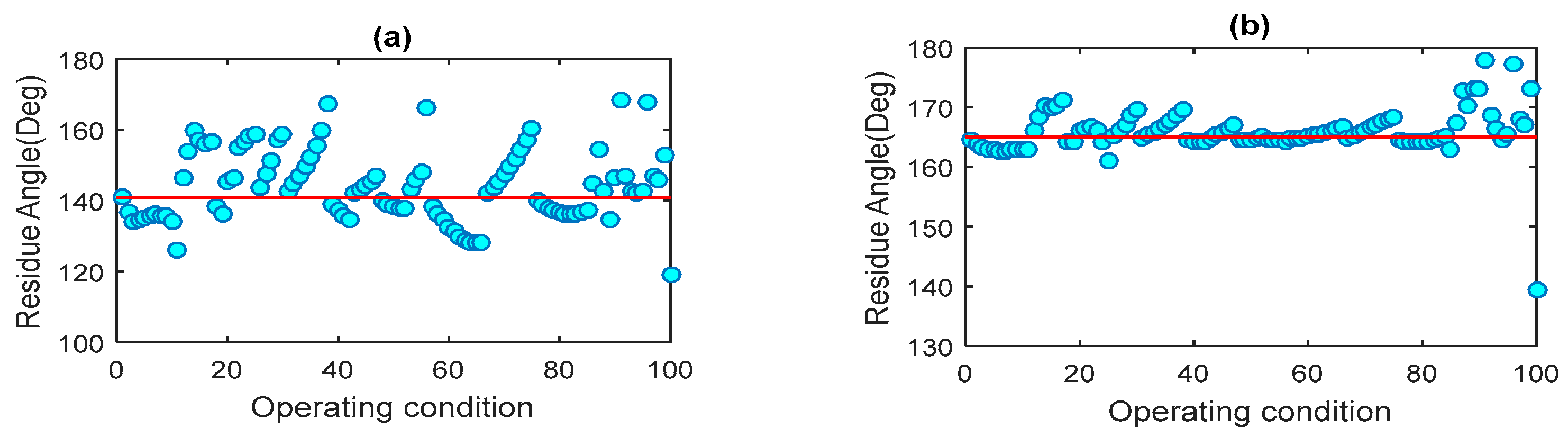
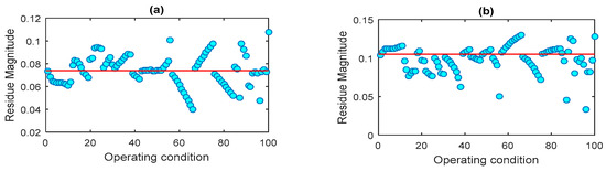
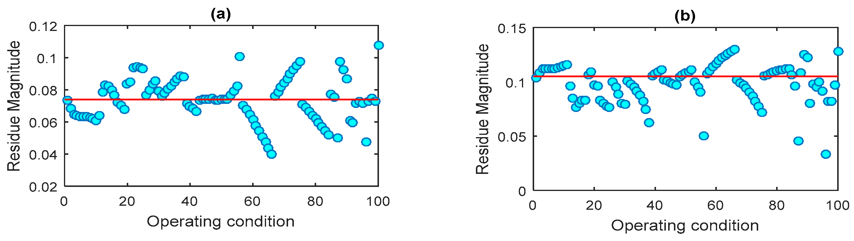
Figure 16 and Figure 17 illustrate the variations in the phase angle and absolute value of the residue for the selected input/output signal pairs across all operating conditions. The results indicate that both the residue magnitude and phase angle exhibit significant variation at Churchill, where a local PSS is present. In contrast, the variations are notably smaller at LG2, where the WADC operates independently without a local PSS. Specifically, the residue phase angle at Churchill deviates from its nominal value by more than 10° in 23 operating conditions, with a maximum deviation of 28° observed when generation at Churchill is increased by 40%. Conversely, at LG2, the residue phase angle exceeds the 10° threshold in only three operating conditions, with the largest deviation being 17°, occurring when the load demand in Montreal is reduced by 30%.
Figure 16.
Variation of residue phase angle across operating conditions with a local PSS installed at Churchill. (a) input: ΔωCHU-LG2, output: CHU. (b) input: ΔωCHU-LG2, output: LG2.
Figure 17.
Variation of residue magnitude across operating conditions with a local PSS installed at Churchill. (a) input: ΔωCHU-LG2, output: CHU. (b) input: ΔωCHU-LG2, output: LG2.
To provide a more comprehensive assessment of the robustness of the designed WADCs, the range and standard deviation of both the residue phase angle and magnitude are calculated and presented in Table 10. The results clearly reveal substantial fluctuations in the residue phase angle at Churchill.
Table 10.
Statistical analysis of residue variations with a local PSS installed at Churchill.
These findings suggest that implementing the WADC at LG2 is likely to offer greater robustness, resulting in more consistent damping performance across a wide range of operating conditions. In contrast, deploying the WADC in parallel with the local PSS at Churchill appears to reduce robustness and may compromise the controller’s effectiveness under certain scenarios.
We now relocate the local PSS from Churchill to LG2. Figure 18 and Figure 19 illustrate the variations in the phase angle and absolute value of the residue for the selected input/output signal pairs across all operating conditions. The results indicate that the phase angle variation is more pronounced at LG2 (with the local PSS) compared to Churchill (without the local PSS).
Figure 18.
Variation of residue phase angle across operating conditions with a local PSS installed at LG2. (a) input: ΔωCHU-LG2, output: LG2. (b) input: ΔωCHU-LG2, output: CHU.
Figure 19.
Variation of residue magnitude across operating conditions with a local PSS installed at LG2. (a) input: ΔωCHU-LG2, output: LG2. (b) input: ΔωCHU-LG2, output: CHU.
As shown in Table 11, the standard deviation of the residue phase angle at Churchill decreases from 11.71° to 3.98° when the local PSS is removed. Conversely, at LG2, the standard deviation increases from 4.74° to 10.01° following the installation of the local PSS. These results confirm that the high variation in the residue phase angle initially observed at Churchill is primarily attributable to the influence of the local PSS on the wide-area control loop.
Table 11.
Statistical analysis of residue variations with a local PSS installed at LG2.
The analysis of the Hydro–Québec system confirms the pattern observed in the four-machine system. Across the two PSS configurations tested (Churchill and LG2), independent WADC operation yields typical phase angle standard deviations of 4–5° with maximum ranges of 32–39°, while parallel PSS/WADC configurations exhibit substantially higher variability with standard deviations of 10–12° and ranges extending to 50–67°. This represents a consistent 2–3× increase in phase angle dispersion when a local PSS operates in parallel with the WADC, corroborating the robustness degradation identified in the four-machine system and demonstrating that the phenomenon scales to larger, more complex power systems.
6. Conclusions
This paper presents a first investigation into the impact of a local PSS on the robustness of input/output signal selection for WADCs. While the conventional hierarchical configuration, wherein the WADC operates in parallel with a local PSS, is widely adopted, our findings challenge its assumed superiority. Using a residue-based analysis that incorporates both magnitude and phase angle variations, we demonstrated that the presence of a local PSS can significantly affect the residue phase angle associated with selected signals, reducing their robustness across varying operating conditions. In contrast, when the WADC operates independently, without a local PSS in parallel, the selected signals show significantly less variation, resulting in more consistent and reliable damping performance. These results, validated on two benchmark test systems, underscore the importance of considering robustness criteria during the signal selection stage.
While comprehensive mitigation strategies require investigation beyond the scope of this exploratory study, the findings suggest preliminary considerations for practitioners. When feasible, selecting WADC output locations at generators without local PSSs tends to improve robustness, yielding a 2–4× reduction in residue phase-angle variability. In cases where parallel PSS/WADC operation is unavoidable, the proposed methodology in Section 4 can be used as a screening tool to identify signal and actuator configurations exhibiting lower phase angle sensitivity across operating conditions. The development of validated and generalizable mitigation approaches, such as adaptive phase compensation or coordinated PSS–WADC tuning strategies, requires deeper investigation of the underlying interaction mechanisms and constitutes an important direction for future research, now motivated by the empirical evidence provided in this work.
Building on the empirical findings of this first investigation, future research should focus on developing rigorous analytical frameworks that explicitly characterize the interaction between parallel local and wide-area feedback loops at the modal level. A promising direction is the derivation of extended residue formulations that account for controller-induced feedback coupling, enabling decomposition of residue phase contributions arising from the plant dynamics, local PSS action, and wide-area control paths. Complementary approaches based on matrix perturbation theory and operating-point-dependent eigenvector sensitivity analysis could provide closed-form insight into how local stabilizers reshape modal observability and controllability, thereby inducing phase angle variability.
From a control–theoretic perspective, structured uncertainty frameworks, geometric residue analysis, and passivity-based methods could be employed to identify fundamental limits and trade-offs between local and inter-area damping objectives under hierarchical control. Extensions beyond linearized models—such as Koopman operator-based analysis—may further capture nonlinear effects under large disturbances. Finally, validation using ambient PMU data from real power systems would allow assessment of the practical relevance of the observed phenomenon under realistic operating conditions. Together, these directions aim to transform the empirical observations reported herein into predictive tools and principled mitigation strategies grounded in solid theoretical foundations.
Author Contributions
Conceptualization, M.B. and I.B.; methodology, M.B.; software, I.B.; validation, P.K., F.R.S.S. and M.R.-G.; formal analysis, M.B. and I.B.; investigation, M.B. and I.B.; resources, P.K., F.R.S.S. and M.R.-G.; data curation, I.B.; writing—original draft preparation, M.B. and A.B.; writing—review and editing, A.B.; visualization, M.B.; supervision, T.A.; project administration, A.B., T.A., P.K., F.R.S.S. and M.R.-G.; funding acquisition, P.K., F.R.S.S. and M.R.-G. All authors have read and agreed to the published version of the manuscript.
Funding
This research received no external funding.
Data Availability Statement
The original contributions presented in this study are included in the article. Further inquiries can be directed to the corresponding authors.
Acknowledgments
Open access funding was provided by ZHAW Zurich University of Applied Sciences. During the preparation of this manuscript, the authors used the free version of ChatGPT (OpenAI, San Francisco, CA, USA) to improve the readability and language of some parts of the text. After using this tool, the authors carefully reviewed and edited the content as needed and take full responsibility for the content of the published article.
Conflicts of Interest
The authors declare no conflicts of interest.
References
- Alhelou, H.H.; Abdelaziz, A.Y.; Siano, P. Wide Area Power Systems Stability, Protection, and Security; Springer: Cham, Switzerland, 2021. [Google Scholar]
- Li, Y.; Yang, D.; Liu, F.; Cao, Y.; Rehtanz, C. Interconnected Power Systems Wide-Area Dynamic Monitoring and Control Applications; Springer: Berlin/Heidelberg, Germany, 2016. [Google Scholar]
- Wang, H.; Du, W. Analysis and Damping Control of Power System Low-Frequency Oscillations; Springer: New York, NY, USA, 2016. [Google Scholar]
- ENTSO-E. Analysis of CE Inter-Area Oscillations of 1st December 2016; ENTSO-E Report; ENTSO-E: Brussels, Belgium, 2017. [Google Scholar]
- ENTSO-E. Oscillation Event 03.12.2017—System Protection and Dynamics WG; ENTSO-E Report; ENTSO-E: Brussels, Belgium, 2018. [Google Scholar]
- Almomani, M.M.; Odienat, A.; Al-Gharaibeh, S.F.; Alawasa, K. The impact of wind generation on low-frequency oscillations in power systems. In Proceedings of the IEEE PES/IAS PowerAfrica Conference, Nairobi, Kenya, 23–27 August 2021. [Google Scholar]
- Liu, C.; Cai, G. Power-oscillation evaluation in power systems with high penetration of renewable power generation based on network virtual inertia. IET Renew. Power Gener. 2019, 13, 138–145. [Google Scholar] [CrossRef] [Scilit]
- Benasla, M.; Denaï, M.; Liang, J.; Allaoui, T.; Brahami, M. Performance of wide-area power system stabilizers during major system upsets: Investigation and proposal of solutions. Electr. Eng. 2021, 103, 1417–1431. [Google Scholar] [CrossRef] [Scilit]
- Benasla, M.; Sevilla, F.S.; Korba, P.; Allaoui, T.; Denaï, M. A criterion for designing emergency control schemes to counteract communication failures in wide-area damping control. IEEE Access 2023, 11, 55911–55924. [Google Scholar] [CrossRef] [Scilit]
- Kamwa, I.; Grondin, R.; Hebert, Y. Wide-area measurement based stabilizing control of large power systems—A decentralized/hierarchical approach. IEEE Trans. Power Syst. 2001, 16, 136–153. [Google Scholar]
- Okou, F.; Dessaint, L.A.; Akhrif, O. Power system stability enhancement using a wide-area signals-based hierarchical controller. IEEE Trans. Power Syst. 2005, 20, 1465–1477. [Google Scholar] [CrossRef] [Scilit]
- Zhang, Y.; Bose, A. Design of wide-area damping controllers for inter-area oscillations. IEEE Trans. Power Syst. 2008, 23, 1136–1143. [Google Scholar] [CrossRef] [Scilit]
- Dotta, D.; Silva, A.S.E.; Decker, I.C. Wide-area measurements-based two-level control design considering signal transmission delay. IEEE Trans. Power Syst. 2009, 24, 208–216. [Google Scholar] [CrossRef] [Scilit]
- Yao, W.; Jiang, L.; Wen, J.; Wu, Q.; Cheng, S. Wide-area damping controller for power system inter-area oscillations: A networked predictive control approach. IEEE Trans. Control Syst. Technol. 2015, 23, 27–36. [Google Scholar] [CrossRef] [Scilit]
- Surinkaew, T.; Ngamroo, I. Hierarchical coordinated wide-area and local controls of DFIG wind turbine and PSS for robust power oscillation damping. IEEE Trans. Sustain. Energy 2016, 7, 943–955. [Google Scholar] [CrossRef] [Scilit]
- Qi, J.; Wu, Q.; Zhang, Y.; Weng, G.; Zhou, D. Unified residue method for design of compact wide-area damping controller based on power system stabilizer. J. Mod. Power Syst. Clean Energy 2020, 8, 367–376. [Google Scholar] [CrossRef] [Scilit]
- Duan, C.; Li, C.; Fang, W.; Yao, W.; Zhang, C.; Jiang, L. Optimizing power system wide-area damping controllers under communication time delays and model reduction errors. Smart Power Energy Secur. 2024, 1, 36–48. [Google Scholar]
- Farsangi, M.M.; Song, Y.; Lee, K. Choice of FACTS device control inputs for damping inter-area oscillations. IEEE Trans. Power Syst. 2004, 19, 1135–1143. [Google Scholar] [CrossRef] [Scilit]
- Heniche, A.; Kamwa, I. Assessment of two methods to select wide-area signals for power system damping control. IEEE Trans. Power Syst. 2008, 23, 572–581. [Google Scholar] [CrossRef] [Scilit]
- Chompoobutrgool, Y.; Vanfretti, L.; Ghandhari, M. Survey on power system stabilizers control and their prospective applications for power system damping using synchrophasor-based wide-area systems. Eur. Trans. Electr. Power 2011, 21, 2098–2111. [Google Scholar]
- Padhy, B.P.; Srivastava, S.C.; Verma, N.K. A coherency-based approach for signal selection for wide-area stabilizing control in power systems. IEEE Syst. J. 2013, 7, 807–817. [Google Scholar] [CrossRef] [Scilit]
- Bai, F.; Liu, H.; Zhu, L.; Liu, Y.; Sun, K.; Wang, X.; Patel, M.; Farantatos, E. A measurement-based control input–output signal selection approach to damp inter-area oscillations. In Proceedings of the IEEE PES Asia-Pacific Power and Energy Engineering Conference (APPEEC), Brisbane, QLD, Australia, 15–18 November 2015; pp. 1–6. [Google Scholar]
- Radwan, M.M.; Azmy, A.M.; Ali, G.E.M.; Elgebaly, A.E. Optimal design and control loop selection for a STATCOM wide-area damping controller considering communication time delays. Int. J. Electr. Power Energy Syst. 2023, 149, 109056. [Google Scholar] [CrossRef] [Scilit]
- Wang, H.F. Selection of robust installing locations and feedback signals of FACTS-based stabilizers in multi-machine power systems. IEEE Trans. Power Syst. 1999, 14, 569–574. [Google Scholar]
- Ray, S.; Chaudhuri, B.; Majumder, R. Appropriate signal selection for damping multi-modal oscillations using low-order controllers. In Proceedings of the IEEE Power and Energy Society General Meeting, Pittsburgh, PA, USA, 20–24 July 2008; pp. 1–7. [Google Scholar]
- Morato, J.; Knüppel, T.; Østergaard, J. Residue-based evaluation of the use of wind power plants with full-converter wind turbines for power oscillation damping control. IEEE Trans. Sustain. Energy 2014, 5, 82–89. [Google Scholar] [CrossRef] [Scilit]
- Linash, P.K.; Pal, B.C. Selection of feedback signals for controlling dynamics in future power transmission networks. IEEE Trans. Smart Grid 2015, 6, 1493–1501. [Google Scholar]
- Ngamroo, I. Wide-area damping controllers of wind and solar power using probabilistic signal selection. IET Renew. Power Gener. 2019, 13, 1351–1359. [Google Scholar] [CrossRef] [Scilit]
- Kundur, P. Power System Stability and Control; McGraw-Hill: New York, NY, USA, 1994. [Google Scholar]
- Kamwa, I.; Samantaray, S.; Joos, G. Optimal integration of disparate C37.118 PMUs in wide-area PSS with electromagnetic transients. IEEE Trans. Power Syst. 2013, 28, 4760–4770. [Google Scholar] [CrossRef] [Scilit]
- Ghahremani, E.; Kamwa, I. Local and wide-area PMU-based decentralized dynamic state estimation in multi-machine power systems. IEEE Trans. Power Syst. 2016, 31, 547–562. [Google Scholar] [CrossRef] [Scilit]
- Benasla, M.; Allaoui, T.; Brahami, M.; Sood, V.K.; Denaï, M. Power system security enhancement by HVDC links using a closed-loop emergency control. Electr. Power Syst. Res. 2019, 168, 228–238. [Google Scholar] [CrossRef] [Scilit]

Disclaimer/Publisher’s Note: The statements, opinions and data contained in all publications are solely those of the individual author(s) and contributor(s) and not of MDPI and/or the editor(s). MDPI and/or the editor(s) disclaim responsibility for any injury to people or property resulting from any ideas, methods, instructions or products referred to in the content. |
© 2026 by the authors. Licensee MDPI, Basel, Switzerland. This article is an open access article distributed under the terms and conditions of the Creative Commons Attribution (CC BY) license.