


Abstract
This paper presents a novel integrated gear drive unit (IGDU), which integrates a high torque density flux-focusing magnetic gear with a V-shaped interior permanent magnet (IPM) motor into a compact structure. The proposed configuration enables direct torque amplification and efficient low-speed, high-torque operation, addressing the inherent torque limitations of conventional electric motors. Critical design parameters, including pole-pair selection, modulation ring dimensions, and stator slot openings, are optimized to enhance torque performance and minimize cogging torque. Finite element analysis (FEA) verifies a maximum torque output of 43.7 Nm. A prototype of the proposed IGDU was fabricated, and experimental validation confirms the effectiveness of the design, with a good match between the measured back-EMF and the simulated one. The results highlight the potential of the proposed machine for compact, high-performance applications such as electric vehicles and industrial drives.
1. Introduction
Gearboxes are essential components across various industries, facilitating torque transmission from the input to the output shaft. While traditional mechanical gear systems offer advantages such as high torque density, they also come with inherent drawbacks [1,2,3,4,5,6,7]. One of the most significant issues is the generation of substantial frictional forces at the meshing points of the gear teeth, which leads to wear, material degradation, and eventual failure. Additionally, mechanical gears require continuous lubrication and cooling to mitigate friction and thermal stress. Other limitations include reduced operational lifespan and large physical size, which can be restrictive in compact or high-performance applications [8,9,10,11]. To address these challenges, researchers and engineers have explored alternative solutions, leading to the development of magnetically actuated gear systems. Among these, coaxial magnetic gears (CMGs) have gained considerable attention. Unlike conventional mechanical gears, CMGs rely on magnetic fields for torque transmission, eliminating direct physical contact between moving components. This non-contact operation significantly reduces frictional losses, wear, and the need for lubrication, while also enhancing efficiency and reliability. As a result, CMGs present a promising alternative for applications requiring high durability, minimal maintenance, and compact design, making them particularly suitable for advanced industrial, aerospace, and renewable energy systems [12,13].
The integration of electrical machine and MG is one of the key approaches to increase output torque, and various magnetic-geared machine (MGM) configurations have been introduced [14,15,16]. Radial integration of an MG with an electric machine results in a compact MGM in which torque production and magnetic gearing are realized within a unified electromagnetic structure. Several radially integrated MGM topologies have been reported in the literature [17,18,19], most commonly featuring an inner stator surrounded by dual PM rotors. In these configurations, the PMs are mounted on both rotors, and the flux modulation segments remain stationary. However, the presence of three distinct air gaps represents a significant limitation, as it increases structural complexity, complicates fabrication and assembly, and adversely affects mechanical robustness. One notable design integrates a magnetic gear with a brushless DC (BLDC) motor, enhancing torque density. In this configuration, the conventional inner rotor of the magnetic gear is eliminated and, instead, the stator winding directly contributes to torque generation. This design, known as the magnetic-geared permanent magnet (MGPM) machine [20,21], offers a more compact structure and reduces overall system weight. Nonetheless, the utilization of common active components for both magnetic gearing and torque production leads to a less effective flux-modulation process and consequently lower torque capability. In [22], a bearingless MGM topology based on the reluctance flux-modulation effect of stator teeth is presented. Although this approach eliminates mechanical bearings and their associated friction losses, the required magnetic suspension control is highly complex, which limits its practical implementation. Beyond radial-flux MGMs, alternative configurations such as axial-flux [23] and transverse-flux MGMs have been proposed [24]. These designs offer potential advantages, including higher torque generation, reduced rotor losses, and improved efficiency compared to their radial-flux counterparts. However, these axial-flux structures require difficult thermal management or rely on salient pole rotors or open slots for flux modulation, which increases torque ripple and introduces more noise and vibration.
This paper proposes a novel integrated gear drive unit (IGDU), in which a high torque density flux-focusing CMG is axially coupled with a V-shaped interior permanent magnet (IPM) motor. Unlike the widely studied magnetic-geared machines and flux-modulated machines, the proposed IGDU integrates a motor and a complete magnetic gear into the same enclosure, while maintaining electromagnetic functional separation between torque production and torque amplification. This structural decoupling enables each subsystem to be independently optimized and allows the magnetic gear to operate with strong flux modulation and high torque transmission capability. Furthermore, owing to the improved magnetic flux utilization in the proposed IGDU, the required torque can be achieved at lower current density compared with radially integrated MGMs, which directly contributes to higher overall drive-system efficiency. The proposed configuration not only enhances torque transmission and mechanical reliability but also simplifies the structural design, making the fabrication of the IGDU more efficient and compact compared to conventional counterparts. This paper is structured as follows: Section 2 details the geometric configuration and operational principles of both the motor and magnetic gear units. Section 3 presents a multi-objective optimization framework that systematically improves the performance of the IGDU while adhering to design constraints, ensuring optimal operation under maximum torque conditions. In Section 4, the optimized design is evaluated through finite element analysis (FEA) and validated against experimental results. Finally, Section 5 summarizes the findings and key contributions of this study.
2. Structure and Operating Principles of the Proposed IGDU
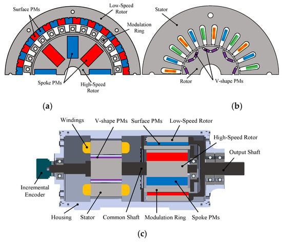
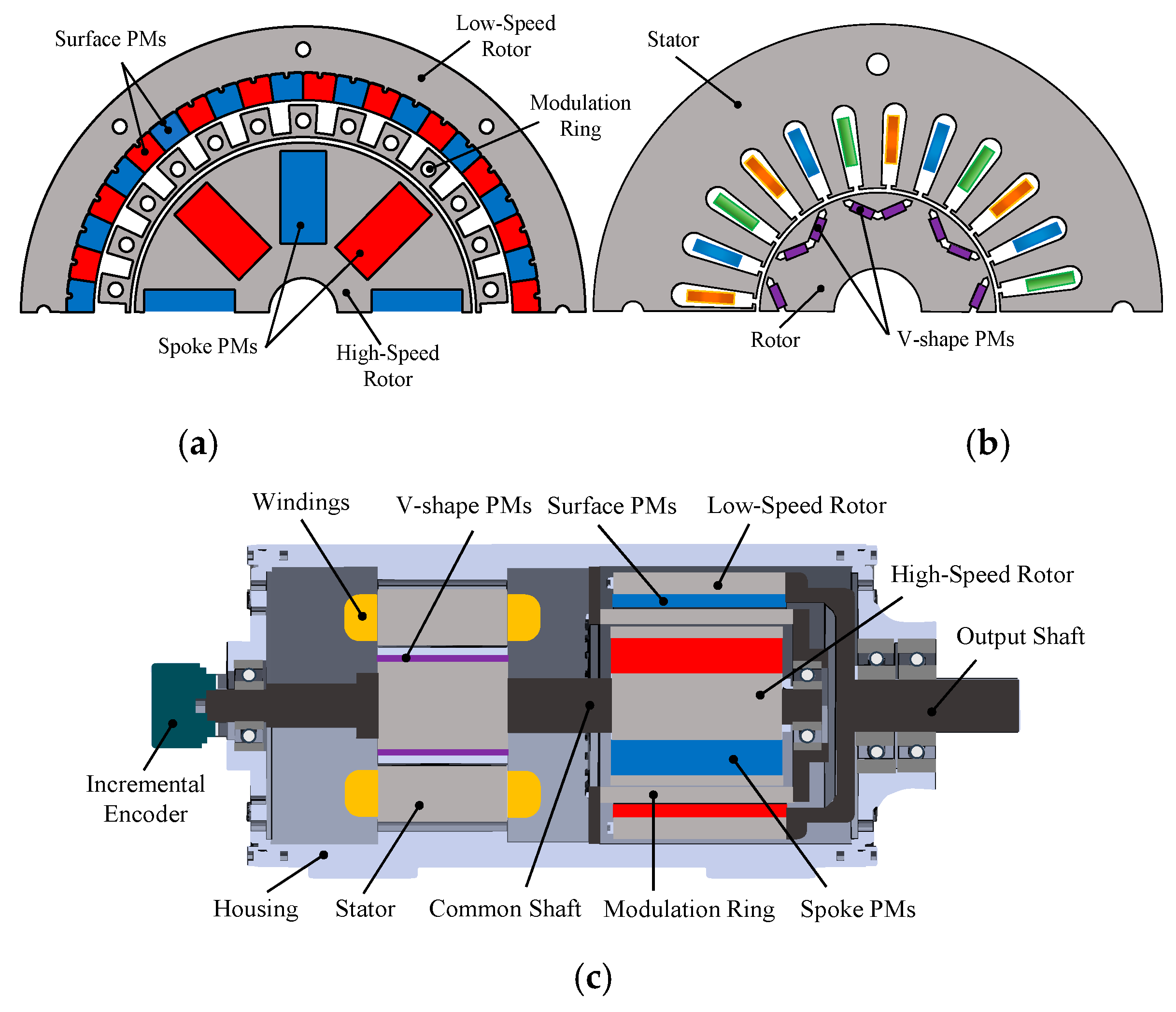
The proposed IGDU consists of two primary components: a flux-focusing CMG and an IPM motor (Huanyee Electromagnetic, Yichang, China). The magnetic gear unit is composed of three distinct and physically separated parts, the inner rotor, the outer rotor, and a modulation ring positioned between these rotating elements, as illustrated in Figure 1a. The motor unit adopts the same structural configuration as a conventional V-shaped IPM motor, with its cross-sectional view depicted in Figure 1b. A stainless-steel common shaft mechanically links the rotor of the IPM motor to the high-speed (HS) rotor of the magnetic gear. The PMs on the HS rotor are arranged in a flux-focusing configuration to enhance magnetic interaction. The torque transmitted via the common shaft is amplified directed by the magnetic gear and subsequently delivered to the load through the low-speed (LS) rotor, as demonstrated in Figure 1c. To ensure mechanical stability, the common shaft is supported by two bearings, one at the housing end and another inside the modulation ring, which is securely fixed to the housing via a centrally positioned disc. Additionally, the output shaft is mounted on two bearings located at the output side to minimize eccentricity and maintain operational precision during motor performance.
Figure 1.
Structure of the proposed IGDU: (a) CMG configuration, (b) IPM motor configuration, (c) cross-sectional view of the mechanical design.
The torque-speed characteristics and overall dimensions of the CMG were primarily influenced by the IPM machine, particularly its gear ratio. Consequently, the electromagnetic design of the CMG and IPM motor was carried out concurrently while accounting for the mechanical constraints of the intended application. The development of the CMG unit is based on the following governing equations [24,25,26]:
where Pm,k denotes the number of pole pairs in the space harmonic flux density distribution, while P represents the number of pole pairs of the PMs. The indices m and k correspond to the space harmonic order, and Ns refers to the number of ferromagnetic pole pieces in the HS rotor. The correlation between these pole pairs is defined by the following equation:
where Ph and Pl represent the number of pole pairs in the HS and LS rotors, respectively. In this study, the selected parameters are Ph = 4, Pl = 22, and Ns = 26. The corresponding speed relationship is given by the following equation [27]:
where ωm,k, ωr, and ωs denote the angular velocity of the spatial harmonic, the rotational speed of the PM rotor, and the angular velocity of the modulation ring, respectively. When the modulation ring remains stationary, the gear ratio can be defined as follows:
Owing to the modulation effect, spatial harmonics of the same order in each air gap interact, enabling torque generation. The torque produced by the HS and LS rotors of the magnetic gear, as a function of the magnetic field distribution, is determined using the following expression [28]:
where Ri and Ro represent the radii of the inner and outer air gaps, respectively. The radial flux density components in these air gaps are denoted by Bri and Bro, while Bθi and Bθo correspond to the circumferential flux density components in the inner and outer air gaps, respectively. Additionally, Ls refers to the stack length of the CMG.
3. Design Optimization of the Proposed IGDU
A parametric sweep-based optimization approach is employed in the design of the proposed IGDU to simultaneously enhance torque capability and reduce cogging torque. The design variables comprise key geometric and topological parameters of both the IPM motor and the CMG, including the slot/pole combination, slot opening width, gear ratio, and the dimensions of the ferromagnetic modulation pole pieces. Since the electromagnetic performance of the IPM motor and the CMG are effectively decoupled in the proposed architecture, the two subsystems can be optimized independently. Accordingly, this section investigates the parametric optimization of the individual components of the proposed IGDU.
3.1. Design of IPM Motor
To identify the most suitable slot–pole combination for the IPM motor, various configurations are evaluated. In this design, integer–slot combinations are prioritized due to their manufacturing simplicity and inherently high winding factors. While fractional–slot combinations can provide smoother output torque and reduced cogging torque, they often introduce greater complexity in winding layout and fabrication. Nevertheless, in the proposed motor, stator slot skewing is employed to effectively mitigate the elevated torque ripple typically associated with integer–slot configurations.
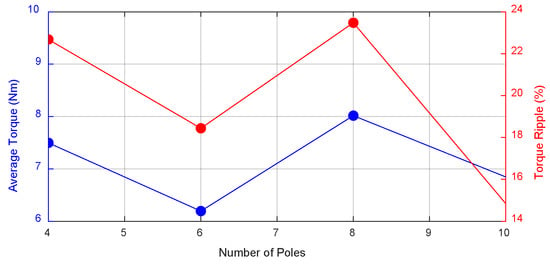
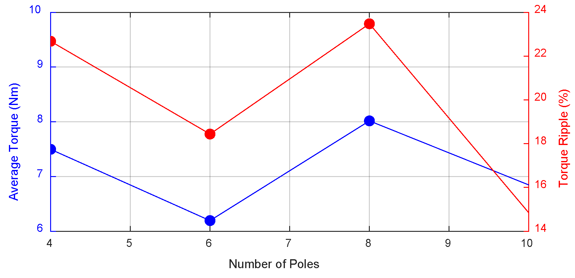
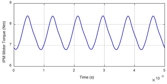
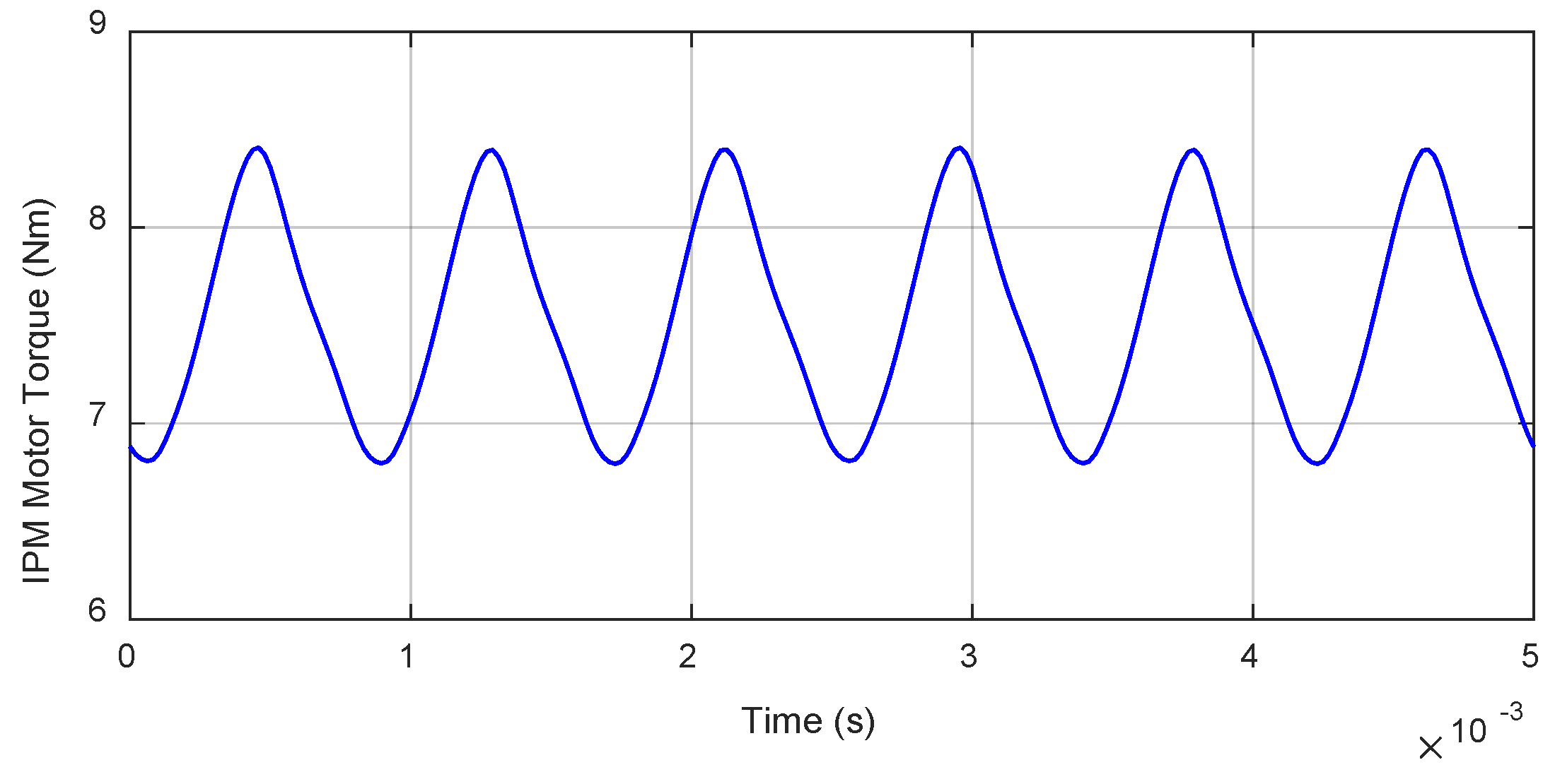
To identify the most suitable slot–pole combination for the IPM motor, several integer-slot winding configurations were evaluated. Figure 2 illustrates the variation in average torque and torque ripple with respect to the number of poles, considering configurations of 4 poles/24 slots, 6 poles/18 slots, 8 poles/24 slots, and 10 poles/30 slots. Among these, the 8 pole/24 slot design delivers the highest average torque due to its favorable winding factor and flux distribution, making it the most effective choice for torque production. Although this configuration exhibits higher torque ripple compared to the 6- or 10-pole alternatives, the ripple can be mitigated through stator slot skewing, while the torque advantage remains inherent to the topology. Hence, the 8-pole configuration is selected as the optimal compromise between performance and practicality, the torque waveform of which is illustrated in Figure 3.
Figure 2.
Effect of slot–pole combination on average torque and torque ripple.
Figure 3.
Torque waveform of the IPM motor with 8 poles/24 slots configuration.
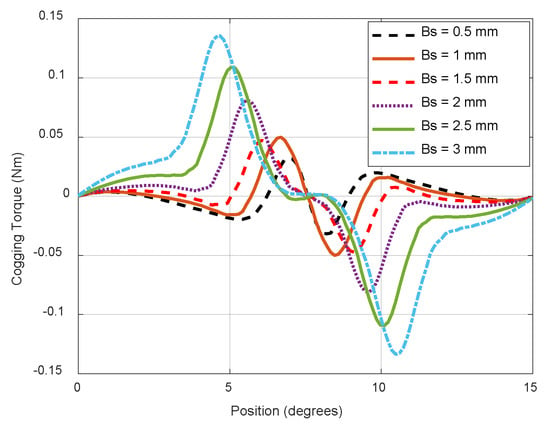
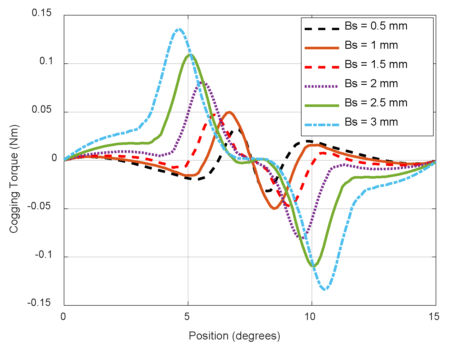
Several factors influence cogging torque in PM motors, including the material composition and geometric structure of the PMs, the air-gap length, and the width of the slot opening. When the PM material, PM configuration, and air-gap length remain constant, the slot opening width becomes a critical parameter affecting cogging torque. Figure 4 illustrates the variation in cogging torque amplitude of the interior IPM motor for different slot opening widths. The results indicate that increasing the slot opening width leads to a higher cogging torque due to enhanced magnetic reluctance variations. However, excessively narrow slot openings are impractical due to constraints related to wire thickness and manufacturability. Given that the wire thickness required for the rated current in this machine is 1 mm, a slot opening width of 1.5 mm is selected as the optimal value based on cogging torque analysis. At this configuration, the cogging torque amplitude is measured at 50 mNm.
Figure 4.
Cogging torque variation with different slot opening values.
3.2. Selection of Gear Ratio
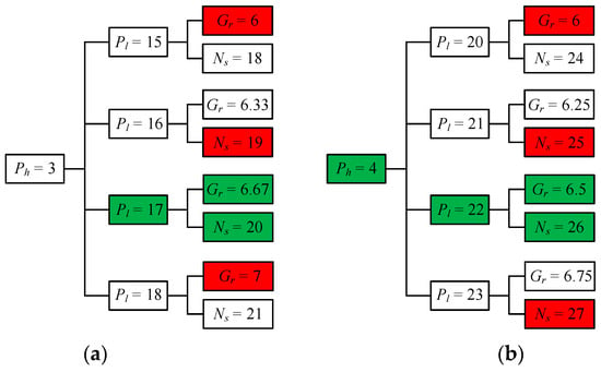
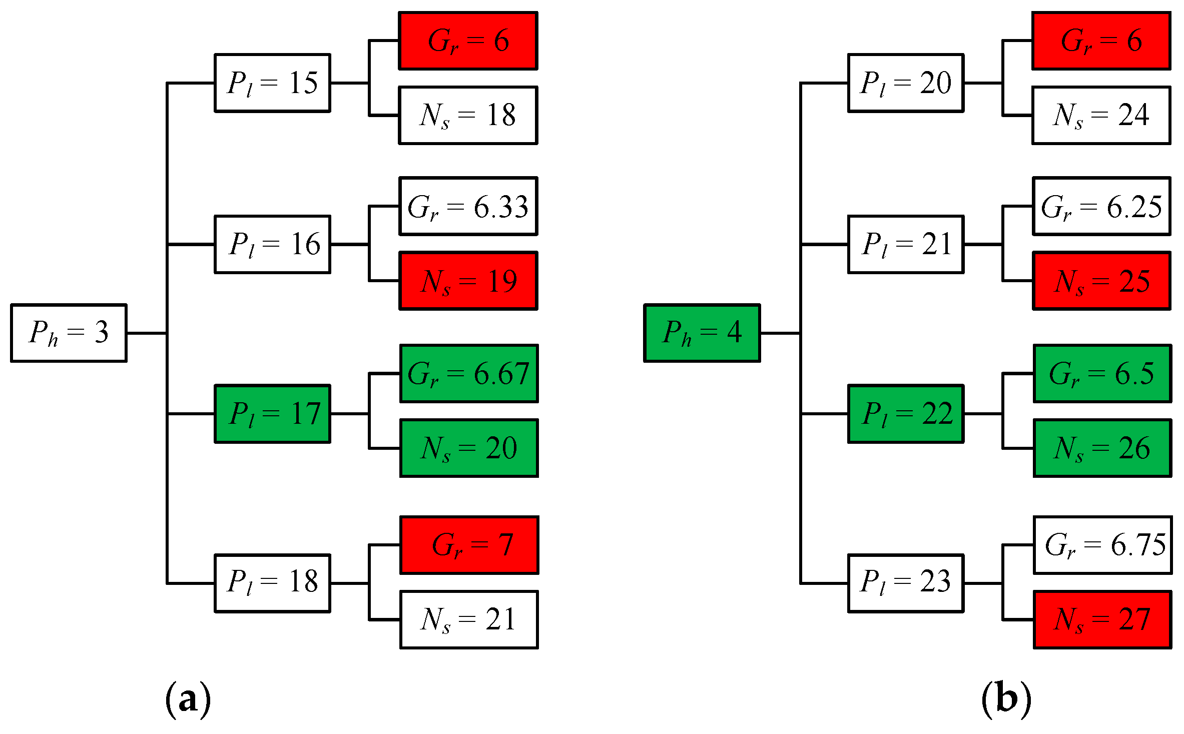
One key objective of the CMG design is to reduce the cogging torque, which is a major contributor of torque ripple and causes vibration. In a CMG, cogging torque arises from the interaction between both the HS rotor and the modulation ring, as well as the LS rotor and the modulation ring. However, due to the high number of pole pairs in the LS rotor, the fundamental amplitude of cogging torque generated between the LS rotor and the modulation ring remains relatively low. Consequently, the dominant source of cogging torque in the CMG stems from the interaction between the HS rotor and the modulation ring. To minimize cogging torque, the least common multiple (LCM) of the HS rotor pole count and the number of ferromagnetic pole pieces in the modulation ring should be maximized. Additionally, ensuring that the number of ferromagnetic pole pieces in the cage rotor is maximized even helps prevent undesirable radial unbalanced forces in the modulation ring [29]. Given that the CMG topology primarily employs a flux-focusing structure, the HS rotor must have a minimum of Ph = 2 pole pairs to facilitate effective flux conduction through the air gap. A pole-pair selection analysis was performed using a tree diagram, as shown in Figure 5, identifying two optimal gear ratio configurations: Gr = 6.67 and Gr = 6.5. These two combinations simultaneously ensure an even number of ferromagnetic segments and a maximized LCM with a non-integer Gr, thereby minimizing cogging torque. To determine the most effective pole-pair combination among these configurations, a 2D-FEA was conducted to assess both the maximum output torque and the torque ripple of the CMG while maintaining a constant PM volume. The results indicate that, with Ph = 4, the CMG achieves a stall torque of Tout = 44.7 Nm, which is close to the 44.8 Nm obtained with Ph = 3. However, the corresponding torque ripple for Ph = 4 is Trip = 2.86%, which is significantly lower than the 6.87% observed for Ph = 3. Based on these findings, the optimal pole-pair combination for the CMG is determined to be Ph = 4, Pl = 22, and Ns = 26.
Figure 5.
Tree diagram of the different pole-pair combinations with: (a) Ph = 3, (b) Ph = 4. Reprinted from ref. [1].
3.3. Optimization of the Modulator Bridge
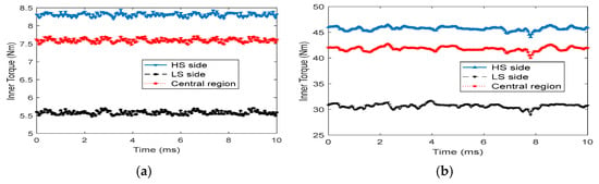
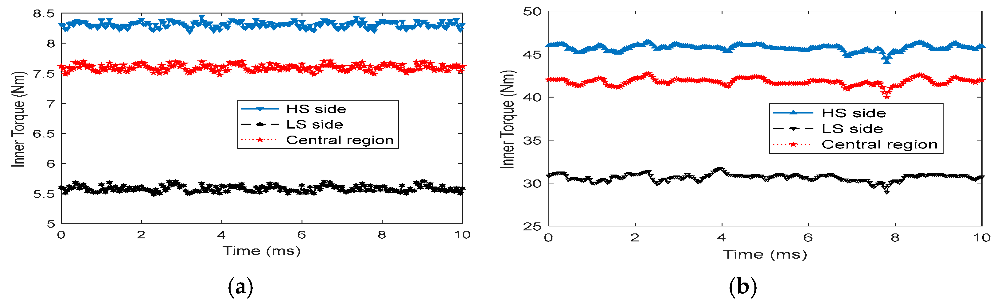
The traditional fabrication method for modulation rings necessitates the manual placement of ferromagnetic segments, leading to inherent symmetry deviations and a complex lamination process. Additionally, the mechanical integrity of the structure remains suboptimal. In this study, a connecting bridge is introduced along the periphery of the modulation ring. While this modification mitigates cogging torque, it also diminishes the modulation effect between ferromagnetic segments, thereby reducing the torque capacity of the CMG. To achieve an optimal balance between torque performance and cogging torque suppression, a design analysis is conducted to determine the most effective location for the connecting bridge. Three potential placement positions are considered, the HS side, the central region, and the LS side of the modulation ring, as depicted in Figure 6. As the thickness of the connecting bridge increases, a slight reduction in torque is observed. To balance structural feasibility and ease of manufacturing, the thickness of the connecting bridge is set to 1 mm. As illustrated in Figure 7, placing the connecting bridge at the HS side results in the maximum torque transmission of the CMG.
Figure 6.
Different configurations of the connecting bridge: (a) HS rotor side, (b) central, (c) LS rotor side.
Figure 7.
Torque transmission comparison for different connecting bridge positions: (a) inner torque, (b) outer torque.
3.4. Ferromagnetic Pole Pieces Dimensions
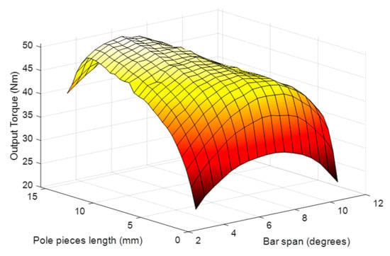
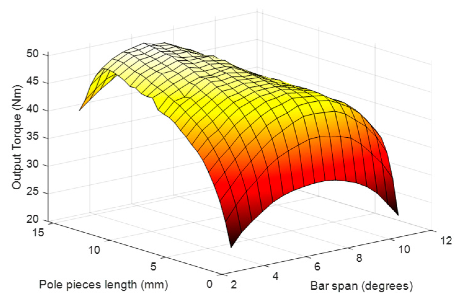
The dimensions and geometry of the ferromagnetic pole pieces play a critical role in determining the modulation performance of the CMG. Therefore, optimizing the shape of these segments is essential to maximize the torque transmission capability. Figure 8 presents the results of a parametric sweep, evaluating the influence of the modulator segment length and angular span on the transmitted torque. To isolate the effect of segment geometry, the length of the ferromagnetic segments is varied while the thickness of the HS and LS rotor yokes is adjusted inversely to ensure the total volume of PMs remains constant. This approach isolates the effect of the ferromagnetic segment length, preventing changes in PM volume or overall magnetic circuit dimensions from influencing the results. The results indicate that the maximum stall torque of approximately 50.7 Nm occurs when the segment’s angular span is 5.5 degrees and its length is 13.5 mm. The final design parameters are given in Table 1.
Figure 8.
Parametric sweep optimization of the ferromagnetic pole pieces shape.
Table 1.
Final parameters of IGDU.
4. Performance Evaluation
In this section, a comprehensive performance evaluation of the proposed IGDU is conducted by 2-dimensional transient time-stepping FEA simulations with a mesh quality of 23,290 elements and 12,860 nodes using commercial JMAG-Designer 23.0. The numerical results are subsequently validated by experimental measurements obtained from the prototype.
4.1. Magnetic Flux Distribution and Harmonic Analysis
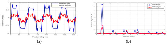
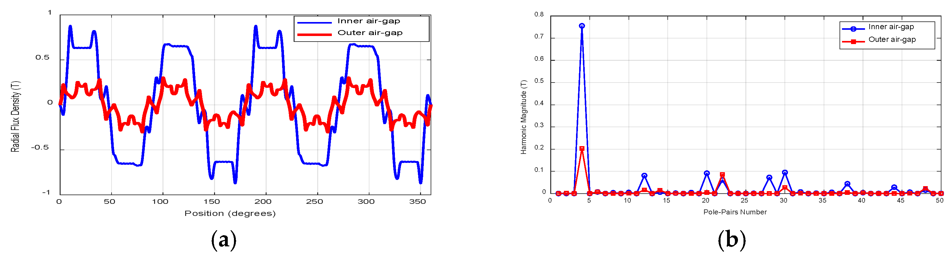
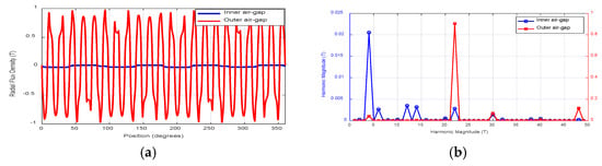
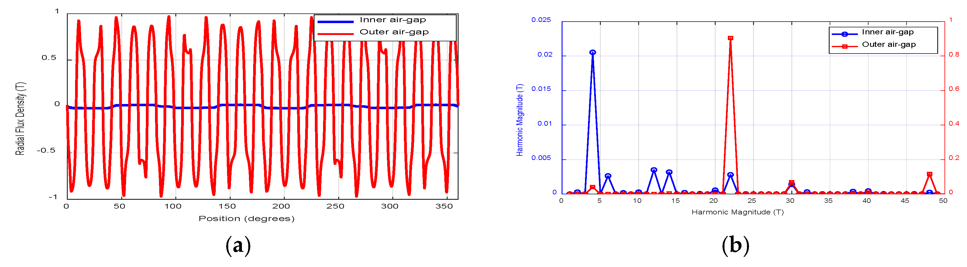
Figure 9 and Figure 10 illustrate the radial flux density distributions within the inner and outer air gaps, generated by the PMs of the HS and LS rotors in the proposed CMG design. As depicted in Figure 9, the fourth harmonic serves as the dominant component of flux density in the inner air gap. In this configuration, a flux-focusing PM arrangement is employed to enhance this harmonic by directing the magnetic flux more effectively toward the inner air gap. These fluxes are subsequently modulated by the ferromagnetic pole pieces, resulting in the generation of the 22nd harmonic component within the outer air gap. Conversely, the PMs on the LS rotor generate a magnetic flux density distribution in the outer air gap, where the dominant harmonic corresponds to the 22nd spatial harmonic, matching the pole pair number of the LS rotor. Similarly, these flux lines are modulated by the ferromagnetic pole pieces, which enhances the fourth harmonic component in the inner air gap. The torque transmission in the proposed CMG is achieved through the coupling between harmonics of the same order in both air gaps, governed by the gear ratio of the system.
Figure 9.
Flux distribution due to the inner PMs: (a) waveforms, (b) FFT.
Figure 10.
Flux distribution due to the outer PMs: (a) waveforms, (b) FFT.
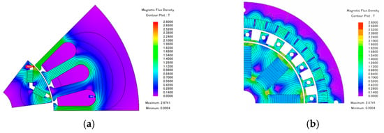
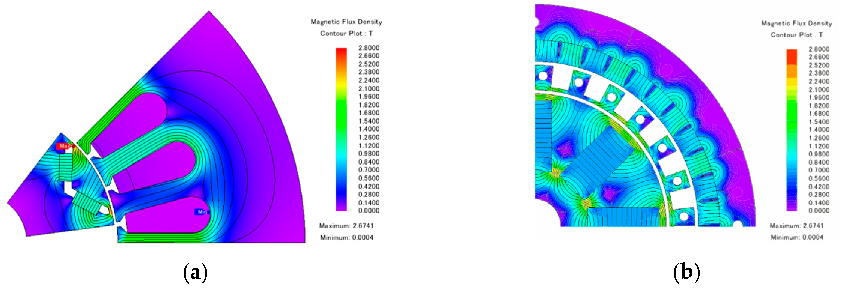
The magnetic flux distribution in the proposed IGDU is depicted in Figure 11. For the IPM motor section, a current density of 9 A/mm2 is applied to the coils, and the simulation is conducted under maximum torque per ampere (MTPA) operation. As shown in Figure 11a, the magnetic and electrical loading of the motor remains within safe limits, as no saturation is observed in the stator yoke. For the CMG section, Figure 11b illustrates the symmetrical flux line pattern at the maximum torque transmission condition. The minimum flux density within the spoke-type PMs is measured at 0.8 T, indicating that the PMs remain within a safe margin against irreversible demagnetization. Additionally, the bridges between adjacent PMs exhibit magnetic saturation, which prevents flux short-circuiting and redirects the magnetic flux into the air gap, enhancing torque transmission efficiency.
Figure 11.
Flux density overlays of the proposed IGDU: (a) IPM motor, (b) CMG.
4.2. Flux Linkages and Back-EMF
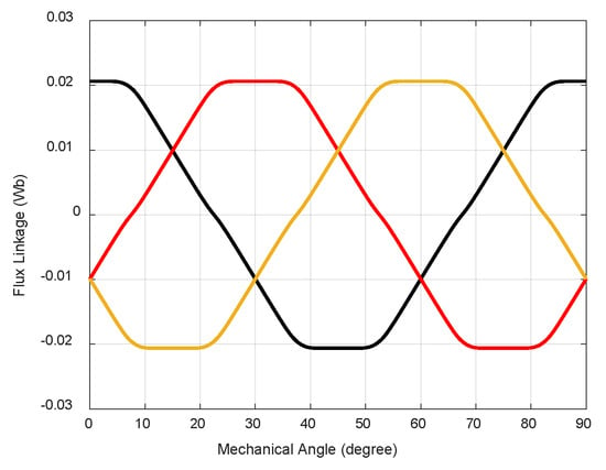
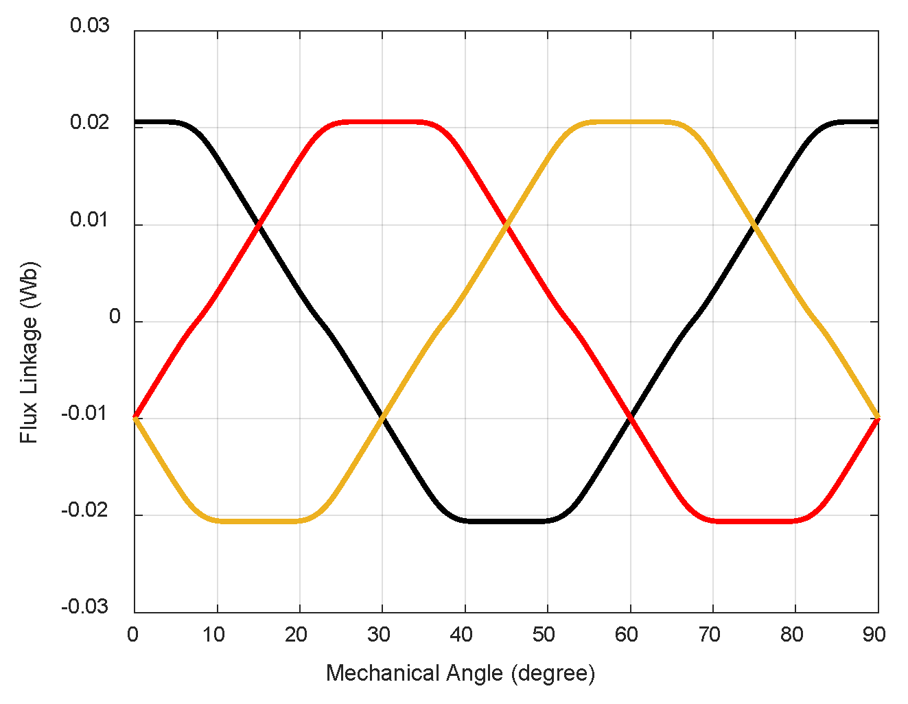
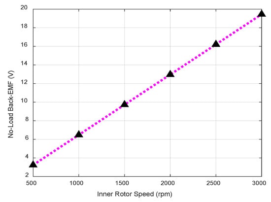
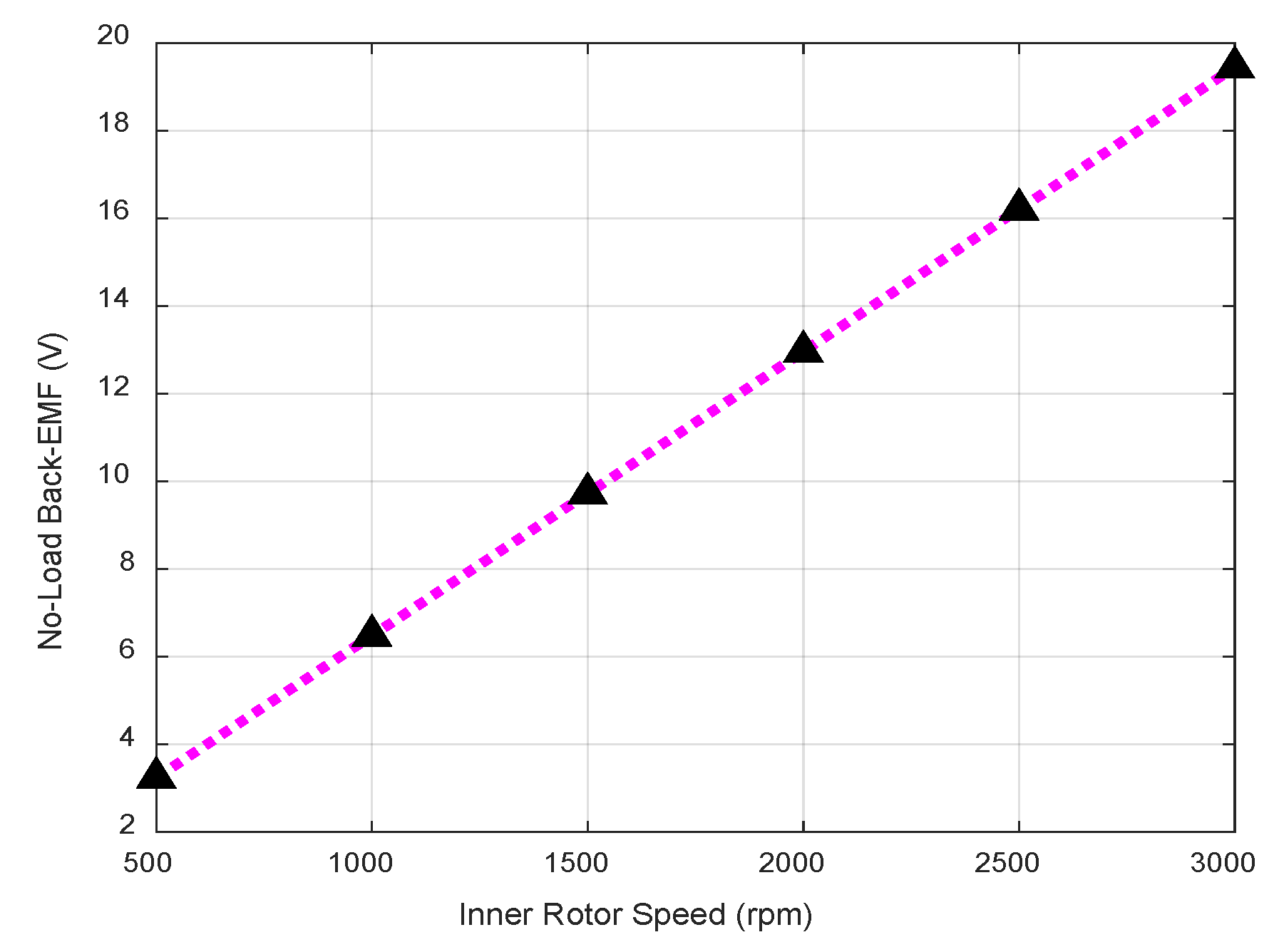
Figure 12 presents the phase flux linkage waveforms of the proposed IGDU. The waveforms exhibit a high degree of symmetry, indicating balanced magnetic excitation and proper phase alignment. Furthermore, the peak flux linkage per phase is approximately 21 mWb. Additionally, the RMS values of the no-load back-EMF at various inner rotor speeds are illustrated in Figure 13. The results clearly demonstrate a linear relationship between the back-EMF magnitude and the rotational speed of the inner rotor, as theoretically expected. Specifically, the RMS output voltage increases from approximately 3.2 V to 19.4 V as the HS rotor speed rises from 500 rpm to 3000 rpm. This behavior indicates that the machine operates effectively over a broad speed range, maintaining consistent flux linkage and magnetic field distribution under no-load conditions.
Figure 12.
Flux linkage waveforms of the IPM motor.
Figure 13.
RMS values of no-load back-EMF at different speeds.  are the measured values and pink dot line is the trend of back-EMF variation at different speeds.
are the measured values and pink dot line is the trend of back-EMF variation at different speeds.
4.3. Torque Characteristics
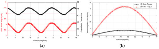
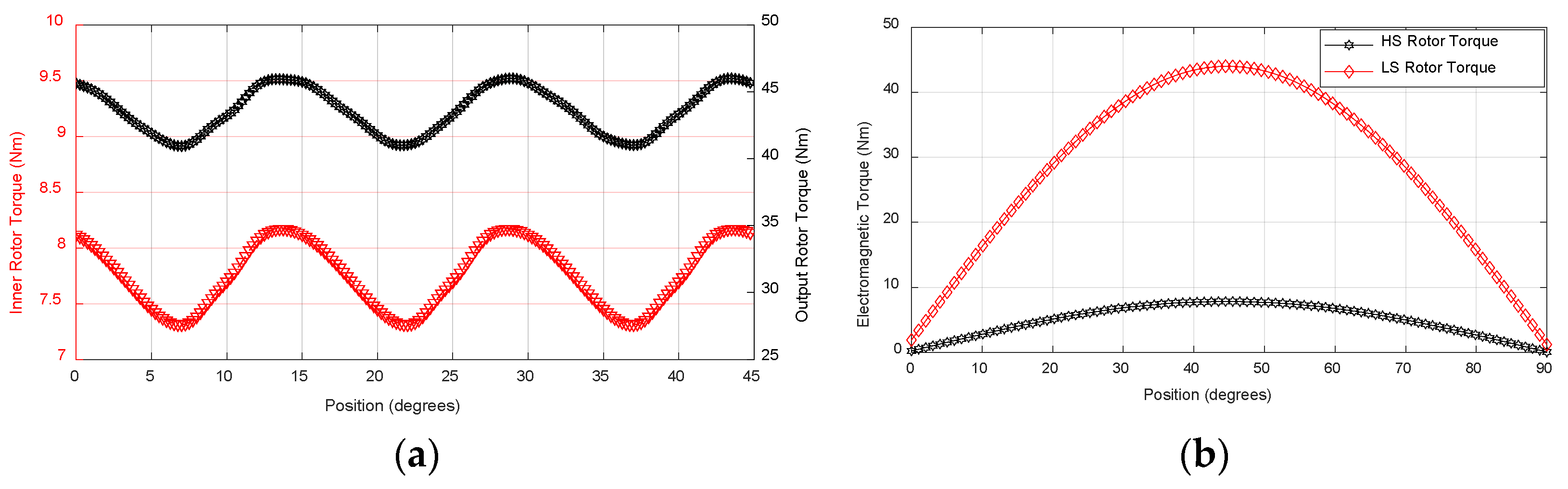
Given that the IPM motor unit generates both magnetic and reluctance torque components, the MTPA control strategy is employed to optimize performance under rated operating conditions. Specifically, the current phase angle is set to α = 114°, while the inner and outer rotors operate at 3000 rpm and 545 rpm, respectively, with an applied current density of 9 A/mm2. Under these conditions, the resulting electromagnetic torque waveforms of the proposed IGDU are presented in Figure 14, reflecting the dynamic and static torque contribution from both the motor and gear units. As illustrated in Figure 14a, the average electromagnetic torques of the HS inner rotor and the LS output rotor are 7.76 Nm and 43.69 Nm, respectively. The corresponding peak-to-peak torque ripple levels are 14.6% for the HS rotor and 2.6% for the LS rotor, relative to their average torque values. These results indicate that the coaxial CMG unit effectively attenuates the torque ripple introduced by the IPM motor, while simultaneously amplifying the torque to meet the output load requirements.
Figure 14.
Torque characteristics of the proposed IGDU: (a) dynamic torque, (b) static torque.
4.4. Loss and Efficiency Maps
The electric motor’s efficiency corresponding to a specific torque-speed point is calculated by
where ω and τ are the rotational speed and torque, and Ploss is the total losses of the motor consisting of different loss components such as ohmic losses, eddy losses, and hysteresis losses.
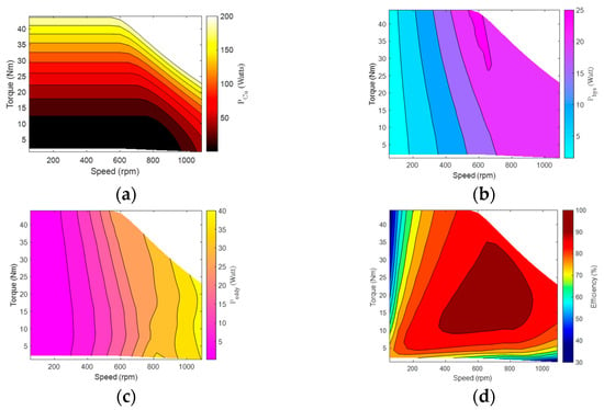
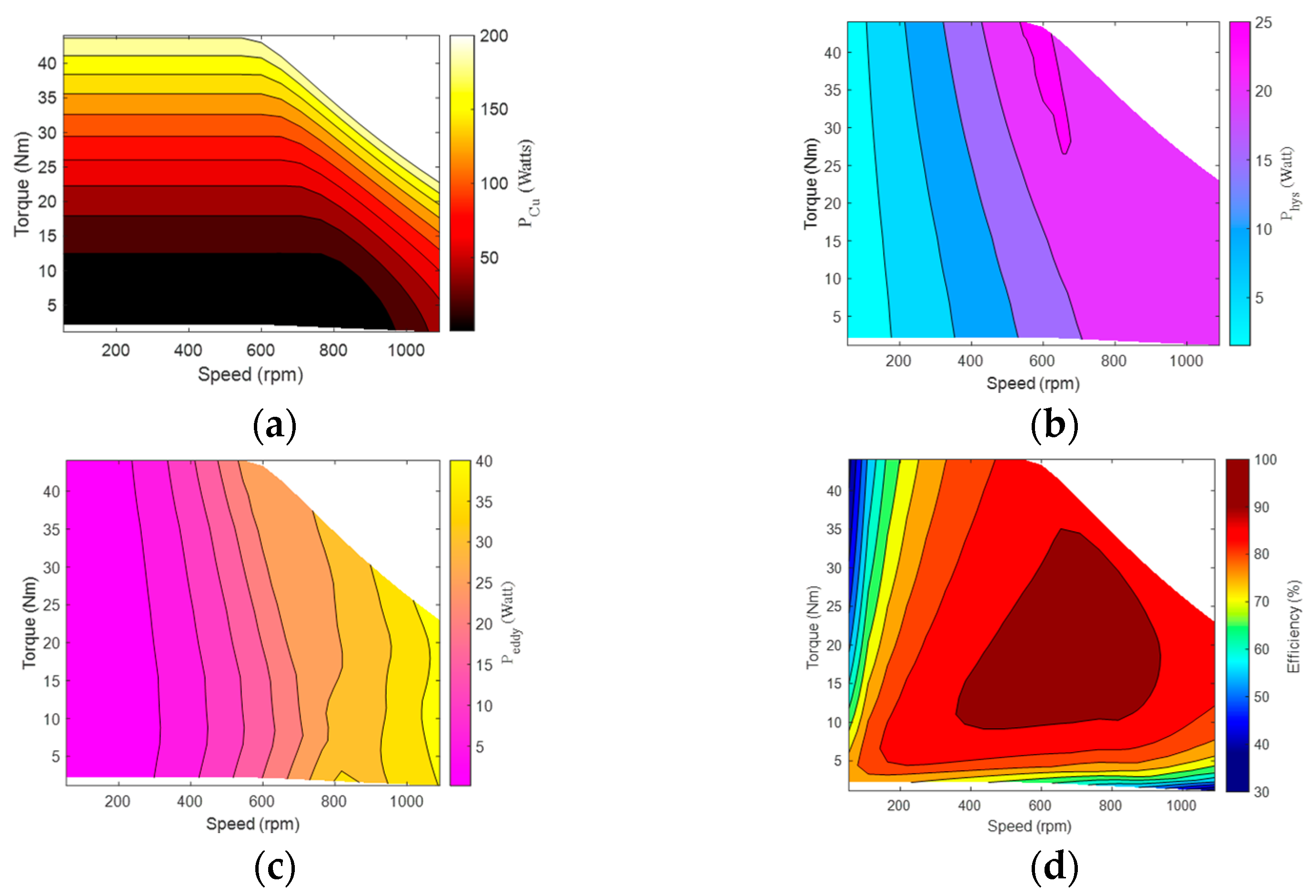
Figure 15 presents the loss and efficiency maps of the proposed IGDU. Copper losses in electric motors are primarily influenced by the current flowing through the windings and the frequency of the supply voltage, the latter contributing through the skin effect. Consequently, as depicted in Figure 15a, copper losses increase proportionally with both torque and speed. Since the CMG unit contains no electrical components, all copper losses in the IGDU originate exclusively from the IPM motor section. Figure 15b,c show the hysteresis and eddy-current loss maps of the proposed IGDU, respectively. For the IPM motor section, these maps are generated in the (Id, Iq) plane at a reference speed of ω0 = 3000 rpm for the HS rotor using FEA. The actual core losses at a given operating speed ω can then be obtained by appropriately scaling the mapped values based on (8), using the corresponding (Id, Iq) current components [30,31]. In contrast, for the CMG part, loss components at various torque-speed operating points are directly computed through FEA and subsequently added to the IPM motor losses to derive the overall loss map of the IGDU.
Figure 15.
Contour plots of the proposed IGDU: (a) copper loss map, (b) hysteresis loss map, (c) eddy loss map, (d) efficiency map.
Finally, the efficiency map of the proposed IGDU is derived from the calculated loss distributions, as illustrated in Figure 15d. The IGDU achieves a peak efficiency of 92.12%, with the highest efficiency occurring near the rated speed. In such machines, overall losses increase primarily due to rising iron losses. Moreover, in the field-weakening region, the need to increase the Id current is the main contributor to the rise in copper losses in IPM motors [32].
4.5. Experimental Verification
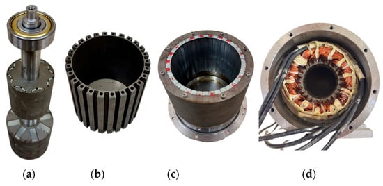
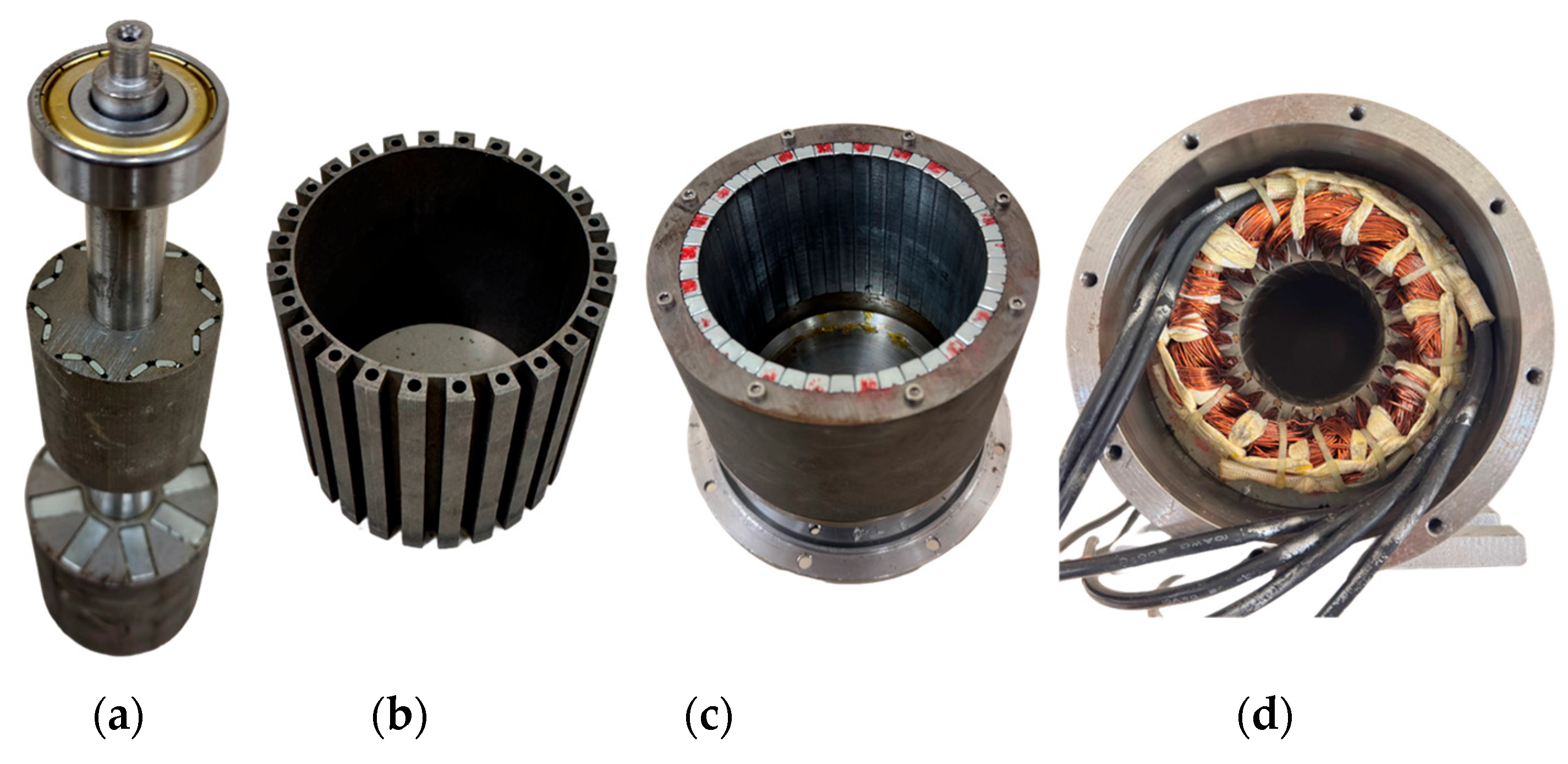
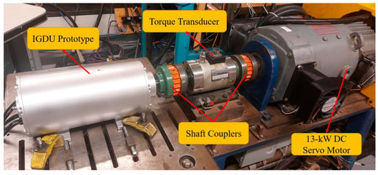
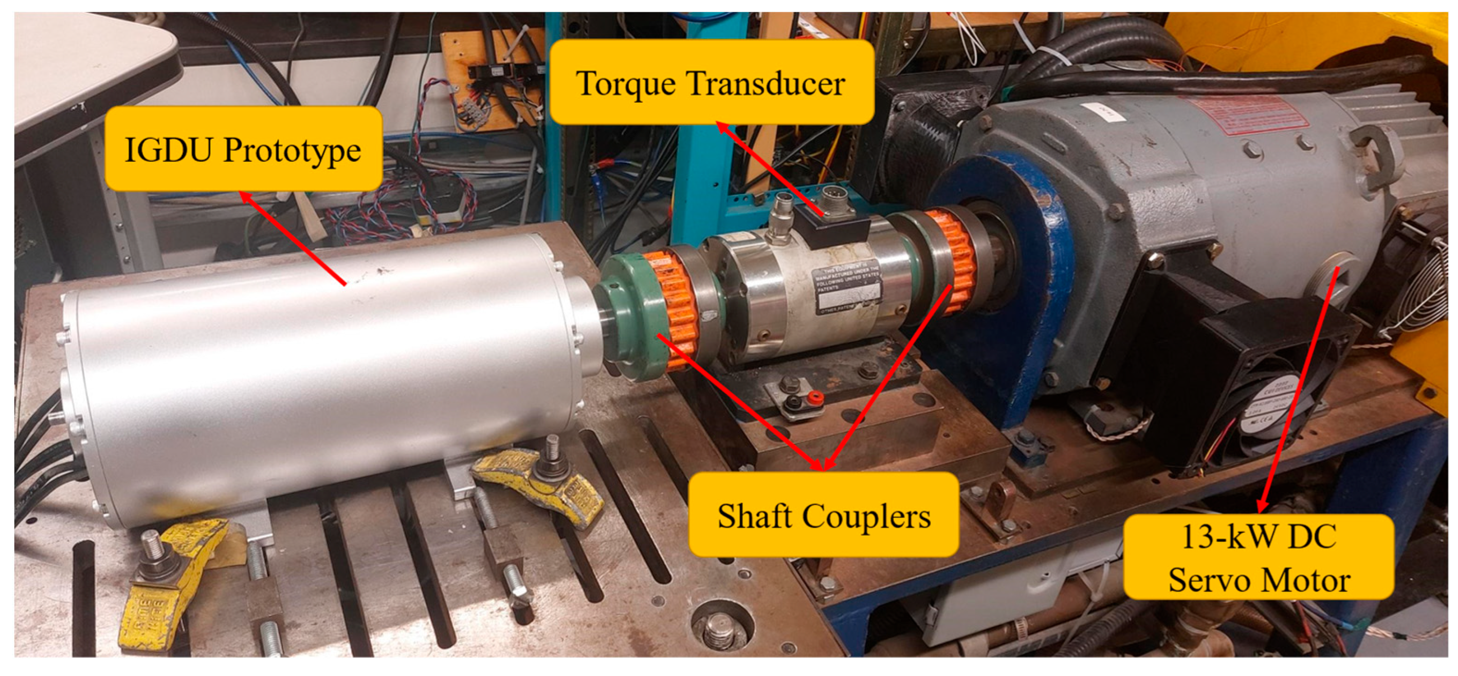
Figure 16 highlights the different laminated parts of the proposed IGDU, including the shared shaft connecting the IPM motor and CMG, modulator, and LS output rotor. One of the primary engineering challenges in the design and development of such an integrated system lies in the precise assembly and structural integration of the modulation ring. A critical consideration is the thickness of the bridges between the modulator segments, which must be minimized to reduce their impact on slip torque transmission. However, this bridge must also maintain sufficient mechanical strength to ensure the structural integrity of the segmented modulation ring. To address this dual requirement, spokes are inserted into the hollow regions of the modulation segments, enabling the ring to be securely fastened to the aluminum end flanges using screws. These spokes are designed to extend through the flange and are firmly fixed in place with nuts, ensuring both rigidity and alignment of the modulation assembly within the IGDU housing. During experimental evaluation, a 13 kW servo motor is employed as a programable load to emulate realistic operating conditions, as shown in Figure 17. The integrated IPM motor within the IGDU is controlled using conventional PMSM control techniques and is therefore fully compatible with standard field-oriented control (FOC) frameworks. The prototype is supplied by a three-phase voltage-source inverter connected to a DC bus, while the gating signals are generated in real time using an OPAL-RT controller implementing pulse-width modulation (PWM). A torque transducer is also used in the test bench for the sampling of the LS rotor torque with an accuracy of ±0.5 Nm.
Figure 16.
Fabricated mechanical parts of the proposed IGDU: (a) common shaft consisting the IPM rotor and HS rotor, (b) modulation ring, (c) LS rotor, (d) stator and housing.
Figure 17.
Test setup of the proposed IGDU. The IGDU prototype on the left is connected to the 13 kW DC servo motor on the right via a torque transducer.
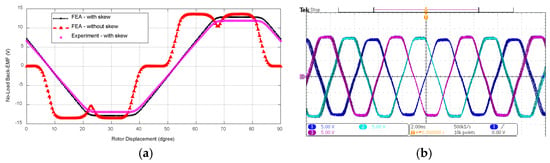
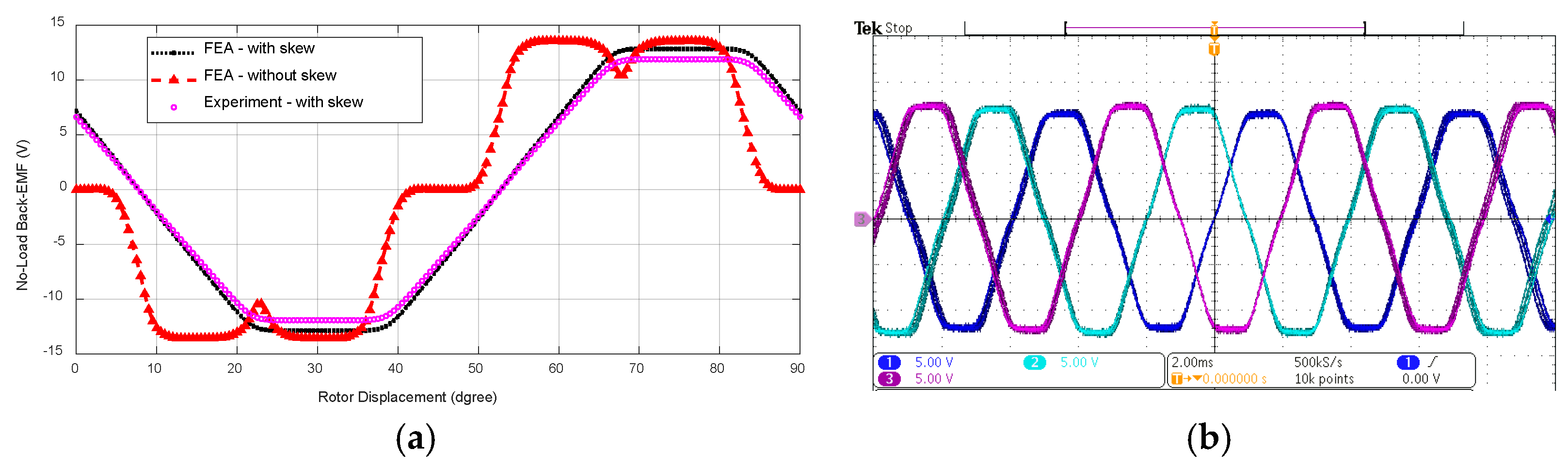
Figure 18 compares the simulated and experimentally measured no-load back-EMF waveforms of the proposed IGDU. The simulation predicts a peak back-EMF amplitude of 12.9 V, while the measured value is 12.6 V. The discrepancy can be attributed to several factors, including deviations in the actual magnetic properties of the PMs from their nominal values, as well as the omission of axial flux leakage and end effects in the simulation model. Despite this difference, the error remains within an acceptable margin, thereby validating the accuracy of the simulation approach and confirming the feasibility and effectiveness of the proposed IGDU design. Moreover, the skewing effect on the back-EMF waveform is also illustrated in Figure 18a. Due to the implementation of 15° of skewing in stator slots, the phase back-EMF waveform has been more sinusoidal compared to the skewless structure. The final design characteristics of the IGDU are summarized in Table 2.
Figure 18.
Back-EMF waveforms at 1500 rpm for the HS rotor: (a) calculated results, (b) tested results.
Table 2.
Final design characteristics of the IGDU.
5. Conclusions
This study introduces a compact, integrated system that combines a CMG with an IPM motor, aiming to replace traditional mechanical gear assemblies or radially coupled MGMs typically used to achieve desired torque and speed characteristics. The structure and fundamental operating principles of the proposed machine are first detailed. Key design parameters such as the number of pole pairs, the geometry of the modulation ring, and the stator slot openings are then analyzed and optimized. Following the optimization process, the electromagnetic performance of the machine is assessed using FEA. A physical prototype is subsequently built and tested, with experimental results confirming both the feasibility of the design and the accuracy of the FEA predictions. In comparison with conventional radially integrated MGM topologies, which typically require high current densities to provide comparable torque levels and exhibit lower efficiency, the proposed IGDU demonstrates a torque density of 24.2 kNm/m3 while maintaining an efficiency of 91.2%. Furthermore, when benchmarked against traditional mechanical-geared drive systems with similar torque ratings, the proposed IGDU offers torque transmission without mechanical contact and providing inherent overload protection. Despite these advantages, the mechanical stresses acting on the rotating components, particularly the inner common shaft connecting the IPM rotor and the HS rotor of the magnetic gear, as well as the long-term thermal behavior of the machine through long-term experimental evaluation, needs further investigation for high-performance applications.
Author Contributions
Resources, Q.W.; Funding acquisition, Q.W.; Investigation, K.A.-H.; Methodology, F.F.-R.; Data curation, A.S.; Writing—original draft, F.F.-R.; Writing—review & editing, K.A.-H.; Visualization, A.S.; Supervision, Q.W.; Project administration, K.A.-H.; Software, F.F.-R. All authors have read and agreed to the published version of the manuscript.
Funding
This research was funded by Natural Sciences and Engineering Research Council of Canada (NSERC) grant number CRSNG ALLRP 597944-25.
Data Availability Statement
The original contributions presented in this study are included in the article. Further inquiries can be directed to the corresponding author.
Conflicts of Interest
The authors declare no conflict of interest.
References
- Shoaei, A.; Farshbaf-Roomi, F.; Wang, Q. Surrogate-based multi-objective optimization of flux-focusing Halbach Coaxial Magnetic Gear. Energies 2024, 17, 608. [Google Scholar]
- Farshbaf-Roomi, F.; Shoaei, A.; Zhu, J.; Wang, Q. High-dimensional optimal design of dual-rotor synchronous reluctance machines based on data-driven torque decomposition. IET Electr. Power Appl. 2025, 19, e12535. [Google Scholar] [CrossRef] [Scilit]
- Kandil, A. Nonlinear dynamic behavior, impact suppression, and stability control of rotor active magnetic bearing systems: A comparative study of fixed and adjustable surplus current strategies. Eur. J. Mech.-A/Solids 2026, 116, 105928. [Google Scholar]
- Shoaei, A.; Farshbaf-Roomi, F.; Wang, Q. Enhanced multi-objective design optimisation of salient pole reluctance magnetic gear using bayesian-optimised Artificial Neural Networks. IET Electr. Power Appl. 2025, 19, e70017. [Google Scholar]
- Lovato, S.; Barosco, G.; Ortombina, L.; Torchio, R.; Alotto, P.; Repetto, M.; Massaro, M. Experimental analysis of a coaxial magnetic gear prototype. Machines 2025, 13, 716. [Google Scholar] [CrossRef] [Scilit]
- Baninajar, H.; Modaresahmadi, S.; Wong, H.Y.; Bird, J.Z.; Williams, W.; Dechant, B. Experimental evaluation of a 63.3:1 dual-stage coaxial Magnetic Gear. IEEE Trans. Energy Convers. 2023, 38, 158–169. [Google Scholar] [CrossRef] [Scilit]
- Zhang, X.; Galluzzi, R.; Amati, N. A hybrid strategy for the design and optimization of coaxial magnetic gears. Machines 2025, 13, 1152. [Google Scholar] [CrossRef] [Scilit]
- Ruiz-Ponce, G.; Arjona, M.A.; Hernandez, C.; Escarela-Perez, R. A Review of Magnetic Gear Technologies Used in Mechanical Power Transmission. Energies 2023, 16, 1721. [Google Scholar] [CrossRef] [Scilit]
- Ji, T.-K.; Baek, S.-W. Optimal design of a coaxial magnetic gear pole combination considering an overhang. Appl. Sci. 2025, 15, 9625. [Google Scholar] [CrossRef] [Scilit]
- Sezen, S.; Yilmaz, K.; Aktas, S.; Ayaz, M.; Dindar, T. Solid core magnetic gear systems: A comprehensive review of Topologies, core materials, and emerging applications. Appl. Sci. 2025, 15, 8560. [Google Scholar] [CrossRef] [Scilit]
- Wu, H.; Niu, S.; Zhang, Y.; Zhao, X.; Fu, W. Fast magnetic field approximation method for simulation of coaxial magnetic gears using AI. IEEE J. Emerg. Sel. Top. Ind. Electron. 2023, 4, 400–408. [Google Scholar] [CrossRef] [Scilit]
- Mateev, V.; Todorova, M.; Marinova, I. Design Aspects of Conical Coaxial Magnetic Gears. Energies 2023, 16, 4191. [Google Scholar] [CrossRef] [Scilit]
- Wang, Y.; Filippini, M.; Bacco, G.; Bianchi, N. Parametric design and optimization of magnetic gears with differential evolution method. IEEE Trans. Ind. Appl. 2019, 55, 3445–3452. [Google Scholar] [CrossRef]
- Atallah, K.; Wang, J.; Calverley, S.D.; Duggan, S. Design and operation of a magnetic continuously variable transmission. IEEE Trans. Ind. Appl. 2012, 48, 1288–1295. [Google Scholar] [CrossRef] [Scilit]
- Shoaei, A.; Wang, Q. A comprehensive review of concentric magnetic gears. IEEE Trans. Transp. Electrif. 2024, 10, 5581–5598. [Google Scholar]
- Li, X.; Wei, Z.; Zhao, Y.; Wang, X.; Hua, W. Design and analysis of surface-mounted permanent-magnet field-modulation machine for Achieving High Power Factor. IEEE Trans. Ind. Electron. 2024, 71, 4375–4386. [Google Scholar]
- Jian, L.; Chau, K.T.; Jiang, J.Z. A magnetic-geared outer-rotor permanent-magnet brushless machine for wind power generation. IEEE Trans. Ind. Appl. 2009, 45, 954–962. [Google Scholar] [CrossRef] [Scilit]
- Jing, L.; Tang, W.; Wang, T.; Ben, T.; Qu, R. Performance analysis of magnetically geared permanent magnet brushless motor for Hybrid Electric Vehicles. IEEE Trans. Transp. Electrif. 2022, 8, 2874–2883. [Google Scholar] [CrossRef] [Scilit]
- Xie, S.; Zuo, Y.; Song, Z.; Cai, S.; Shen, F.; Goh, J.; Han, B.S.; Hoang, C.C.; Lee, C.H. A magnetic-geared machine with improved magnetic circuit symmetry for hybrid electric vehicle applications. IEEE Trans. Transp. Electrif. 2024, 10, 2170–2182. [Google Scholar]
- Wu, F.; El-Refaie, A.M. Permanent magnet vernier machine: A Review. IET Electr. Power Appl. 2019, 13, 127–137. [Google Scholar] [CrossRef] [Scilit]
- Jo, I.-H.; Lee, H.-W.; Jeong, G.; Ji, W.-Y.; Park, C.-B. A study on the reduction of cogging torque for the skew of a magnetic geared synchronous motor. IEEE Trans. Magn. 2019, 55, 1–5. [Google Scholar]
- Kumashiro, A.; Chen, L.; Fujii, Y.; Chiba, A.; Gruber, W.; Amrhein, W.; Jungmayr, G. Novel reluctance-type magnetic-geared motor integrated with high-speed bearingless motor. IEEE Trans. Ind. Appl. 2024, 60, 3808–3819. [Google Scholar]
- Fu, W.; Wu, Q.; Niu, S.; Chen, Y.; Guo, X. An enhanced axial-flux magnetic-geared machine with dual-winding design for Electric Vehicle Applications. CES Trans. Electr. Mach. Syst. 2023, 7, 239–247. [Google Scholar] [CrossRef] [Scilit]
- Wang, M.; Zheng, P.; Tong, C.; Zhao, Q.; Qiao, G. Research on a transverse-flux brushless double-rotor machine for Hybrid Electric Vehicles. IEEE Trans. Ind. Electron. 2019, 66, 1032–1043. [Google Scholar]
- Atallah, K.; Howe, D. A novel high-performance magnetic gear. IEEE Trans. Magn. 2001, 37, 2844–2846. [Google Scholar] [CrossRef] [Scilit]
- Mai, Q.; Hu, Q.; Chen, X. Electromagnetic–Structural Coupling Analysis and Optimization of Bridge-Connected Modulators in Coaxial Magnetic Gears. Energies 2025, 18, 2069. [Google Scholar] [CrossRef] [Scilit]
- Wang, L.L.; Shen, J.X.; Luk, P.C.K.; Fei, W.Z.; Wang, C.F.; Hao, H. Development of a magnetic-geared permanent-magnet brushless motor. IEEE Trans. Magn. 2009, 45, 4578–4581. [Google Scholar]
- Jian, L.; Chau, K.T. A coaxial magnetic gear with halbach permanent-magnet arrays. IEEE Trans. Energy Convers. 2010, 25, 319–328. [Google Scholar] [CrossRef] [Scilit]
- Alosa, C.; Immovilli, F.; Lorenzani, E. Design and optimization of a magnetic gear for a conveyor system application. In 2022 International Conference on Electrical Machines (ICEM); IEEE: New York, NY, USA, 2022; pp. 434–440. [Google Scholar]
- Roshandel, E.; Mahmoudi, A.; Kahourzade, S.; Soong, W.L. Efficiency maps of Electrical Machines: A tutorial review. IEEE Trans. Ind. Appl. 2023, 59, 1263–1272. [Google Scholar]
- Mahmoudi, A.; Soong, W.L.; Pellegrino, G.; Armando, E. Efficiency maps of Electrical Machines. In 2015 IEEE Energy Conversion Congress and Exposition (ECCE); IEEE: New York, NY, USA, 2015. [Google Scholar]
- Roshandel, E.; Mahmoudi, A.; Kahourzade, S.; Yazdani, A.; Shafiullah, G. Losses in efficiency maps of electric vehicles: An overview. Energies 2021, 14, 7805. [Google Scholar] [CrossRef] [Scilit]



Disclaimer/Publisher’s Note: The statements, opinions and data contained in all publications are solely those of the individual author(s) and contributor(s) and not of MDPI and/or the editor(s). MDPI and/or the editor(s) disclaim responsibility for any injury to people or property resulting from any ideas, methods, instructions or products referred to in the content. |
© 2026 by the authors. Licensee MDPI, Basel, Switzerland. This article is an open access article distributed under the terms and conditions of the Creative Commons Attribution (CC BY) license.