


Abstract
To address the malfunction and unreliable operation of traditional open discharge gaps in high-altitude environments (with sandstorms and low pressure), which are prone to interference from factors like electrode corrosion and contamination, this study proposes an intelligent sealed neutral point protection device for transformers. Its core is a sealed discharge gap filled with nitrogen gas, effectively isolating it from external conditions and significantly stabilizing the power frequency discharge voltage. Innovatively, an active breakdown technology is introduced. Overvoltage signals at the transformer neutral point are acquired in real time via a capacitive voltage divider. After processing by a microcontroller unit (MCU), if both the amplitude and duration meet the preset thresholds, the MCU triggers a pulse to actively induce a discharge at the gap’s low-voltage end, enabling controlled breakdown. This allows the transient discharge voltage to be raised to 3–4 times the steady-state value, avoiding overlap with the surge arrester’s residual voltage. Tests confirm that the gap breaks down stably only when both amplitude and duration conditions are met, remaining reliable otherwise. This design successfully resolves the critical issues of failure and maloperation under both steady-state and transient overvoltages in high-altitude settings, significantly improving protection selectivity and reliability, and offering a novel solution for transformer safety in such regions.
1. Introduction
Power transformers are the core hub equipment of the power grid, and their neutral point grounding method and protection strategy directly affect the system’s insulation coordination, the reliability of relay protection operations, and the insulation safety of the equipment itself. When the system encounters abnormal conditions such as lightning strikes, switching overvoltages, or ground faults, the neutral point potential may rise sharply [1,2]. Without effective protection, this can severely threaten the insulation of transformer windings, and even lead to severe accidents such as equipment damage and large-scale power outages. Therefore, for some 110–220 kV transformers with non-directly grounded neutral points, the installation of a neutral point protection device is required. The transformer neutral point protection device serves as a critical line of defense in the power system to ensure the safe operation of major equipment. Its core functions are to limit neutral point overvoltage and provide a fault current path. Designing reliable and efficient neutral point protection devices is essential for maintaining grid stability and equipment lifespan [3,4].
The transformer neutral point protection device primarily consists of components such as a discharge gap, surge arrester, current transformer, and relay protection. Its operational logic is as follows: under normal operating conditions, neither the discharge gap nor the surge arrester operates; when an isolated ungrounded system experiences a single-phase ground fault with loss of grounding or an open-phase fault, the discharge gap operates to protect the insulation of the transformer neutral point and the surge arrester; under lightning overvoltage conditions, the surge arrester operates to limit the overvoltage at the transformer neutral point, while the discharge gap remains inactive [2,4].
In recent years, research on transformer neutral point protection devices has advanced along several complementary paths. One primary direction focuses on the engineering analysis, optimization, and standardization of conventional gap technologies. This includes foundational analyses of neutral point overvoltage scenarios and protection challenges [5], as well as investigations into fault characteristics influenced by different grounding methods [6]. Concurrently, significant efforts have been dedicated to establishing engineering standards for open-type gaps by systematically analyzing field failures to enhance base reliability [7]. Complementing this, studies continue to refine gap technologies through the analysis of composite horn gaps or gap arrester configurations [8,9,10].
The other main research focus pursues intelligent control and precise operational logic for gaps, guided by fundamental insulation coordination principles [11]. This direction encompasses foundational work on the triggering characteristics of sphere-gap switches [12] and the development of novel controllable gaps utilizing three-electrode systems with intelligent circuits [13]. This is further exemplified by the development of triggered discharge gaps, where early work demonstrated the feasibility of using overvoltage identification and active triggering to improve coordination [14]. Recent research has significantly advanced this paradigm by providing a systematic, experimental, and simulation-based study on the triggered discharge characteristics of sphere gaps, offering critical parameters for matching with various surge arrester models [15].
However, despite these advancements, a critical application gap persists, particularly for high-altitude environments. The devices in widespread engineering use, as well as the primary focus of both standardization and intelligent control studies, remain open-type discharge gaps. These structures are inherently vulnerable to external environmental factors. This vulnerability can disrupt the precise voltage coordination required for reliable operation, leading to maloperation or failure-to-trip—a risk further complicated by complex overvoltage mechanisms [16]. Therefore, a significant disconnect exists: while intelligent control studies achieve precise operation under controlled conditions, and standardization efforts address uniform configuration, neither sufficiently resolves the core reliability challenge posed by the exposure of open gaps to harsh, variable high-altitude climates. This limitation underscores the necessity for a novel solution that integrates intelligent control with an environmentally robust design.
Based on the technical approach of combining an enclosed discharge gap with active breakdown triggering, this paper designs an intelligent enclosed neutral point protection device for high-altitude transformers. The enclosed discharge gap effectively mitigates the impact of external factors under high-altitude conditions, while the intelligent active breakdown device, through real-time monitoring and analysis of neutral point overvoltage, controls a pulse triggering mechanism to actively initiate gap discharge. This design effectively prevents maloperation or failure-to-trip of the transformer neutral point protection device, offering a novel solution for neutral point protection of transformers in high-altitude regions.
2. Overall Design Concept
Aiming at the issues exposed by the existing transformer neutral point protection devices in high-altitude environments and their susceptibility to maloperation under transient overvoltages, this paper proposes and designs an intelligent enclosed neutral point protection device. The core design concept is as follows:
First, an enclosed discharge gap structure is adopted, with the interior filled with insulating gas at a certain pressure. This structure effectively isolates external environmental interference, significantly reduces the impact of external factors on the discharge voltage value, and enhances the stability of the discharge voltage.
Second, the device incorporates active breakdown technology. Specifically, a controllable pulse-triggering device is installed at the low-voltage end of the enclosed discharge gap. The device continuously monitors and analyzes the overvoltage signals at the transformer neutral point. Once the discharge conditions are met, it activates the pulse-triggering device to generate a discharge pulse at the low-voltage end of the gap. This low-voltage-end pulse discharge rapidly triggers a through-discharge from the high-voltage end to the low-voltage end of the gap, achieving active and controllable breakdown of the entire discharge gap. This technology enables the discharge voltage of the gap under transient overvoltages to reach 3–4 times or more of its steady-state discharge voltage, thereby avoiding overlap with the residual voltage range of surge arresters. It effectively addresses the issues of traditional discharge gaps being prone to maloperation under transient overvoltages and potential failure to operate under steady-state overvoltages.
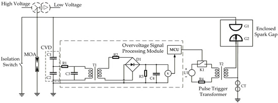
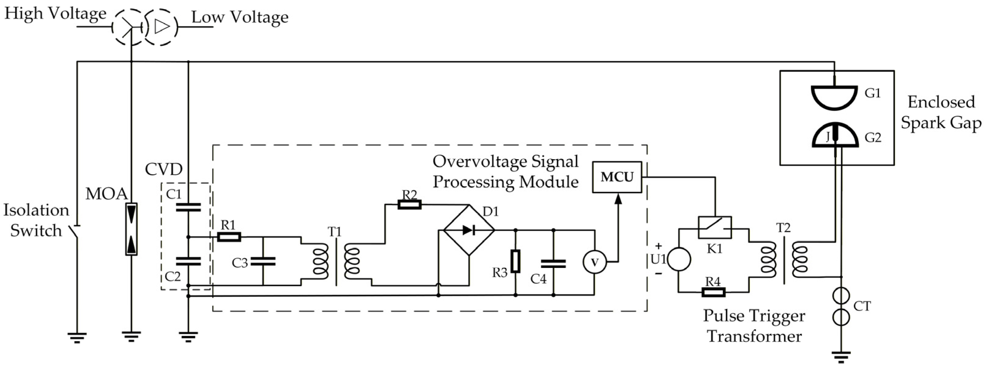
Based on the aforementioned design concept, the main wiring diagram of the intelligent sealed neutral point protection device for high-altitude transformers is designed as shown in Figure 1. The main protection circuit is formed by connecting the maintenance switch, surge arrester (MOA), capacitive voltage divider (C1, C2) with a voltage division ratio of 1000:1, and sealed discharge gap (G1–G2) in parallel; this parallel combination is then connected in series between the transformer neutral point and ground. The capacitive voltage divider extracts the overvoltage signal from the neutral point. This signal is subsequently processed by an RC filter (R1, C3), a rectification and charging circuit (R2, D1, R3, C4), and the microcontroller unit (MCU) monitors both the amplitude and duration of the voltage across the storage capacitor C4. A current transformer (CT) is connected in series between the low-voltage end of the discharge gap (G2) and ground to monitor the breakdown current. When the MCU determines that both the amplitude and duration of the overvoltage meet the preset thresholds, it activates the pulse triggering module: the controllable switch K1 is closed, allowing the power supply U1 to energize the pulse transformer T2, which generates a high-voltage pulse at the triggering electrode J. This pulse actively initiates the breakdown of the sealed gap (G1–G2), thereby achieving controllable and reliable protection against neutral point overvoltages.
Figure 1.
Main wiring diagram of the neutral point protection device.
The capacitive voltage divider is responsible for acquiring and stepping down the overvoltage signal from the transformer neutral point. The transformer neutral point signal passes through a filtering module (composed of R1 and C3) and a rectification and charge–discharge module (composed of R2, D1, R3, and C4) to charge capacitor C4. The central processing unit (MCU) detects both the amplitude and duration of the voltage across capacitor C4. When both the voltage amplitude and duration meet the preset thresholds, the MCU issues a pulse triggering command to close the controllable switch K1. Upon closing the controllable switch K1, power supply U1 energizes the pulse triggering transformer T2, raising the voltage of the pulse triggering electrode J. This initiates a discharge at the low-voltage end G2 of the discharge gap via electrode J, releasing plasma. Consequently, a discharge is triggered from the high-voltage end G1 to the low-voltage end G2, ultimately achieving active breakdown of the discharge gap.
3. Key Component Design
The key components of the intelligent enclosed neutral point protection device for high-altitude transformers designed in this paper are the enclosed discharge gap and the intelligent active breakdown device. The enclosed discharge gap is designed to enhance the stability of the discharge voltage, thereby preventing maloperation. The intelligent active breakdown device is responsible for acquiring, analyzing, and assessing the overvoltage signals from the transformer neutral point, as well as controlling the pulse triggering mechanism to achieve active breakdown of the discharge gap.
3.1. Design of Enclosed Discharge Gap
3.1.1. Discharge Gap
According to the insulation level and overvoltage parameters specified for 110 kV transformer neutral points in DL/T 1848 [1], this paper adopts 80 kV as the design target for steady-state overvoltage. This value is derived by applying a 1.1-times safety margin to the maximum steady-state overvoltage of 72.74 kV, aiming to prevent maloperation of the discharge gap under steady-state overvoltage conditions. Additionally, the steady-state operating voltage of 56.7 kV under single-phase ground fault conditions in an ungrounded system is selected as the design target for stable discharge after the activation of the pulse-triggering device.
Commonly used electrodes in discharge gaps include rod–rod electrodes, sphere–sphere electrodes, and plate–plate electrodes. Among these, the sphere–sphere electrode discharge gap offers better discharge stability and concentration compared to the rod–rod electrode, owing to its more uniform electric field distribution [17,18]. In comparison to the plate–plate electrode, it is more prone to discharge under lightning conditions, thereby enhancing the sensitivity of electrode discharge during lightning discharge scenarios. Based on the design requirements of this device, a sphere–sphere gap (with a sphere diameter of 125 mm—a common standard size for the relevant voltage class and widely studied in the context of standard sphere gaps [17,18])—is adopted as the discharge gap.
For an enclosed discharge gap, the insulation medium also requires design consideration. Typically, nitrogen, SF6, a mixed gas (nitrogen/SF6 = 8:2), and dry air are used as insulating media for gas gaps. This paper conducted experiments to screen these four gas media.
According to the test results, the following conclusions can be made:
- When nitrogen or dry air was used as the insulation medium, with 56.7 kV applied to the high-voltage end of the discharge gap, active breakdown of the discharge gap could be achieved via pulse control by adjusting the gap distance in both cases.
- When SF6 or the gas mixture was used as the insulation medium, the active breakdown control of the discharge gap could not be achieved due to the arc-quenching properties of SF6.
- For SF6 and the gas mixture, even after multiple adjustments of the discharge gap distance and gas pressure, it was difficult to simultaneously meet both the power frequency withstand voltage of approximately 75 kV and the power frequency discharge voltage of 56.7 kV (with pulse intervention).
- Moreover, given that dry air contains complex components such as oxygen, rapid oxidation of the discharge gap can occur under high temperatures during discharge.
Based on the above analysis, this paper selects nitrogen as the insulation medium for the enclosed discharge gap. Based on the empirical formula for the breakdown voltage of sphere–sphere electrodes [17], the discharge gap distance required to meet the design specifications under a nitrogen pressure of 0.2 MPa is calculated to be 15 mm.
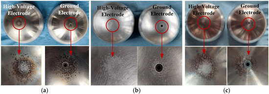
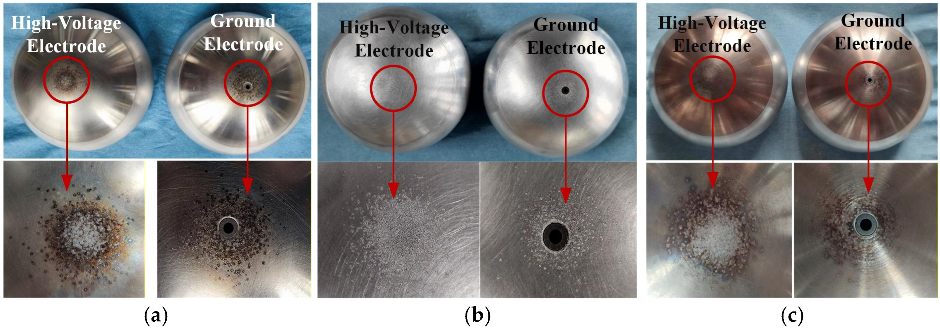
Regarding the material of the discharge gap, discharge tests were conducted 500 times on three types of gap materials: stainless steel, aluminum alloy, and copper–tungsten alloy. The typical material damage levels after discharge are shown in Figure 2. Based on comparative analysis of the smoothness at the discharge locations, the following conclusions are drawn: aluminum alloy develops burrs after discharge, which affects the stability of gap discharge. In contrast, stainless steel and the copper–tungsten alloy maintain relatively smooth surfaces after discharge and do not impair discharge stability. Among these, the copper–tungsten alloy exhibits the best resistance to breakdown and ablation. However, in practical applications, if cost is considered, the price of copper–tungsten alloy electrodes is 11.7 times that of stainless steel. Therefore, stainless steel can be optimally selected as the material for the discharge gap.
Figure 2.
Post-500-shot breakdown damage assessment of electrodes fabricated from different materials. (a) Stainless steel electrode, (b) aluminum alloy electrode, (c) copper–tungsten alloy electrode.
Experimental verification demonstrates that the discharge gap consistently achieves stable breakdown at voltages of 80 ± 2 kV, while remaining non-conductive within the voltage range of 72.74~74 kV, thus meeting the design requirements.
3.1.2. Cylindrical Shell Design
Due to the adoption of an enclosed discharge gap design, the housing used to enclose the gap must additionally account for the ability to withstand the pressure generated by discharge arcs. The mechanical design methodology for the cylindrical shell, including the pressure withstand and thermal stability calculations presented in this subsection, follows the approach established in our prior work [19]. The enclosed discharge gap designed in this project has a rated voltage of 110 kV. Under a transformer capacity of 120 M/W, its short-circuit current is 2.01 kA.
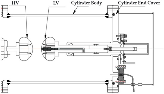
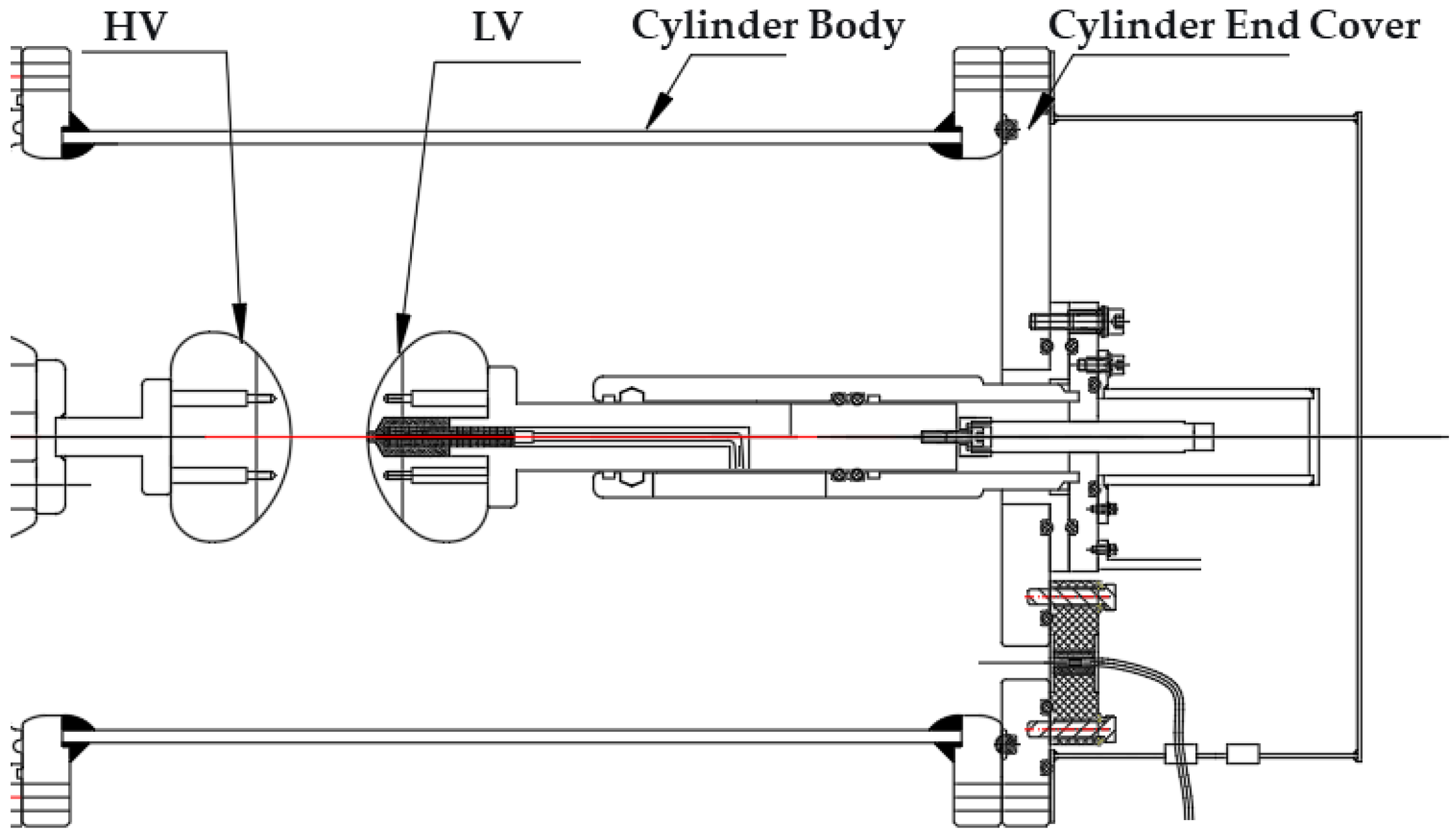
The assembly structure of the discharge gap is shown in Figure 3. The chamber is cylindrical, with a length of 510 mm, a diameter of 305 mm, and a volume of 0.037 m3. It is filled with nitrogen-insulating gas at a pressure of 0.2 MPa and constructed from aluminum alloy. The high-voltage end of the discharge gap is fixed on a contact base, while the low-voltage end is mounted on the side cover plate of the cylinder. In designing this cylindrical shell, several key parameters—including the design pressure, wall thickness, and mechanical load—must be considered. The wall thickness is determined based on both the internal pressure and the required thermal stability to prevent burn-through during fault conditions. Furthermore, the shell is designed to withstand external forces during transportation and installation without permanent deformation or impairment of performance.
Figure 3.
Assembly structure at the discharge gap.
Regarding the shell design pressure, the primary consideration is whether the gas pressure inside the chamber under fault current conditions remains below the shell’s failure test pressure. The calculation of gas pressure P is directly linked to the electrical fault energy dissipated within the sealed gap. The key inputs to this calculation are the arc voltage (U) and the arc current (I), which are derived from the transformer’s fault conditions. The arc voltage U is estimated based on the electric field distribution within the sphere–sphere gap and typical arc voltage gradients for such electrode configurations under sustained fault conditions, leading to a conservative design value of 400 V.
When calculating the gas pressure P under these fault current conditions, the gas within the chamber is treated as an ideal gas, and all energy from the arc is assumed to increase the internal energy of the gas. Based on the formula for thermal energy generated by the arc and the ideal gas law, the following discretized formula for gas pressure can be derived:
where U—arc voltage (V), I—RMS value of arc current (A), h—arc thermal efficiency coefficient, taken as h = 5 × 10⁻⁴ (K−1), cv—specific heat capacity of the gas, T—gas temperature, and m—mass of the gas.
Based on the discretized calculation formula above, with an arc voltage of 400 V, a current of 2.01 kA, and considering that the continuous discharge time of the neutral point protection device is generally ≥0.5 s—and in some fault scenarios where arc extinguishing fails or circuit breaker protection coordination is inadequate, the discharge duration may extend to 1 s—a protection operation time of 1 s is adopted for this device. Through computational programming, the maximum gas pressure during the protection operation time is determined to be 0.178 MPa, which is well below the shell failure test pressure of 2.5 MPa, thus meeting the design requirements.
Regarding shell thickness, the primary consideration is whether the short-circuit operation time of the device is less than the shell burn-through time. The formula for calculating the burn-through time of an aluminum shell is as follows:
where t—shell burn-through time (ms), d—shell wall thickness (mm), and I—RMS value of the fault current (kA).
Calculations show that with wall thicknesses of 6 mm and 7 mm, the corresponding shell burn-through times are 1.224 s and 1.609 s, respectively. With an appropriate margin considered, a wall thickness of 7 mm is selected.
In the design of the shell, the number of bolts and the thickness of the flange must also be considered. Based on relevant calculation methods outlined in the Electrical Engineering Handbook, the number of bolts on the mating surface is determined to be 12, and the flange thickness is set at 25 mm, both of which meet the requirements for engineering applications.
3.2. Design of Intelligent Active Breakdown Device
The device developed in this study employs an intelligent active breakdown device to prevent maloperation or failure-to-trip of the transformer neutral point protection device. This intelligent active breakdown device primarily consists of a neutral point overvoltage signal acquisition module and a pulse triggering module.
3.2.1. Neutral Point Overvoltage Signal Acquisition Module
The transformer neutral point overvoltage signal acquisition module consists of two parts, a capacitive voltage divider and an overvoltage signal acquisition module, as shown in Figure 1. The capacitive voltage divider steps down the overvoltage signal from the transformer neutral point and outputs it to the overvoltage signal acquisition module. After filtering and rectification by this module, the energy storage capacitor C4 is charged. The amplitude and duration of the voltage across capacitor C4 are then detected, and the signal is transmitted to the central processing unit (MCU). By comparing the signal with preset thresholds in the MCU, if both the amplitude and duration of the voltage across capacitor C4 meet the required conditions, the MCU issues a pulse triggering command to control the relay closing. This achieves pulse control, thereby enabling the active breakdown of the discharge gap.
The high-arm capacitance of the capacitive voltage divider is set at 1.6 nF, and the low-arm capacitance at 1.6 μF, giving a voltage ratio of 1000:1. The full capacitive voltage divider has a lightning impulse withstand voltage of 325 kV and a power-frequency withstand voltage of 140 kV. Furthermore, voltage division ratio tests conducted on the capacitive voltage divider show that when the applied voltage is 40 kV or higher, the error in the voltage division ratio ranges from 1% to 2%, which meets the requirements for practical engineering applications.
The overvoltage signal acquisition module comprises a filtering unit, a capacitor charging–discharging unit, and a central processing unit (MCU). The filtering module employs a second-order RC filter circuit, primarily retaining voltage signals within the 50 Hz to 200 Hz frequency range. The capacitor charging–discharging unit uses an RC charging–discharging circuit, with measured charging times around 80 ms. Concurrently, tests on the relationship between the input overvoltage and the charging voltage across capacitor C4 show that the error between the input voltage and the charging voltage ranges from 3% to 9%. Given the substantial margin reserved for the discharge gap control voltage, this meets the requirements for engineering applications.
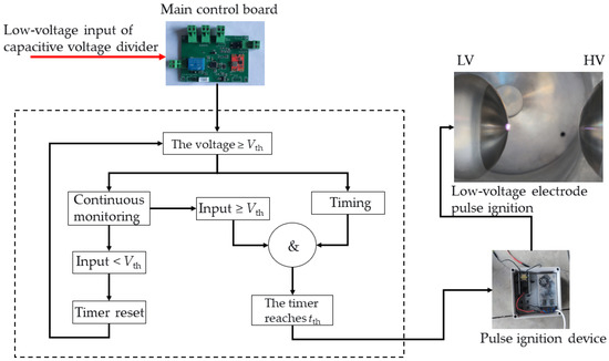
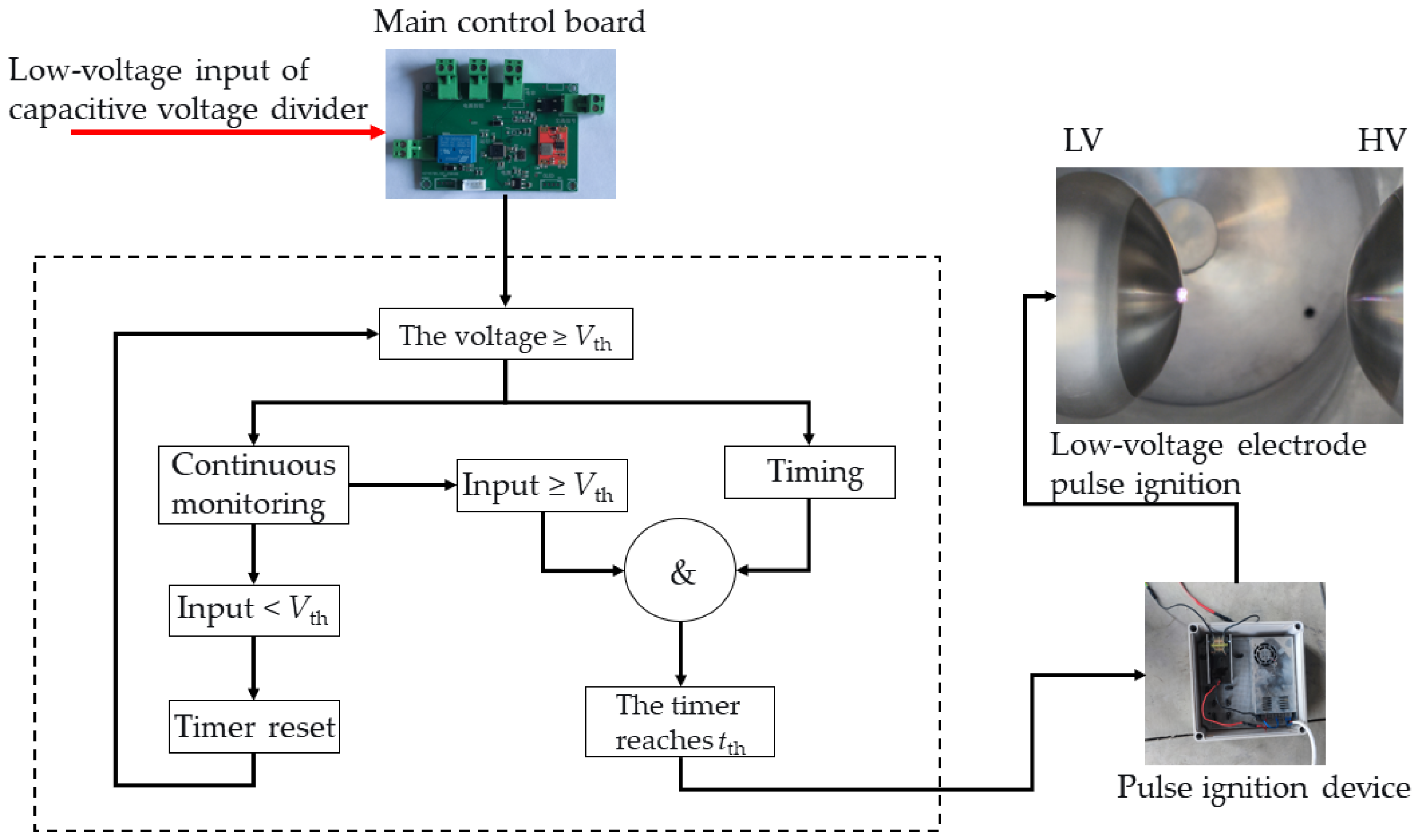
The central processing unit (MCU), selected as the STM32F103C8T6 chip, serves as the intelligent core of the device. It executes the dual-criteria decision algorithm critical to the device’s operational selectivity. The workflow, detailed in Figure 4, involves (1) receiving the conditioned overvoltage signal; (2) continuously monitoring and comparing the signal amplitude against the preset voltage threshold (Vth); (3) only if V ≥ Vth is met, an internal timer is activated to measure the duration for which this condition holds; (4) the measured duration is then compared against the preset time threshold (tth); and (5) a control command to trigger the pulse generator is issued if and only if both criteria are satisfied simultaneously (i.e., (V ≥ Vth) and (t ≥ tth)). This precise logic enables the device to intelligently discriminate between transient overvoltages (where duration is insufficient) and sustained steady-state faults (where both conditions are met), thereby directly addressing the maloperation and failure-to-trip issues outlined in the Introduction. The experimental verification of this logic is presented in Section 4.
Figure 4.
Workflow diagram of the overvoltage signal acquisition module.
3.2.2. Pulse Triggering Module
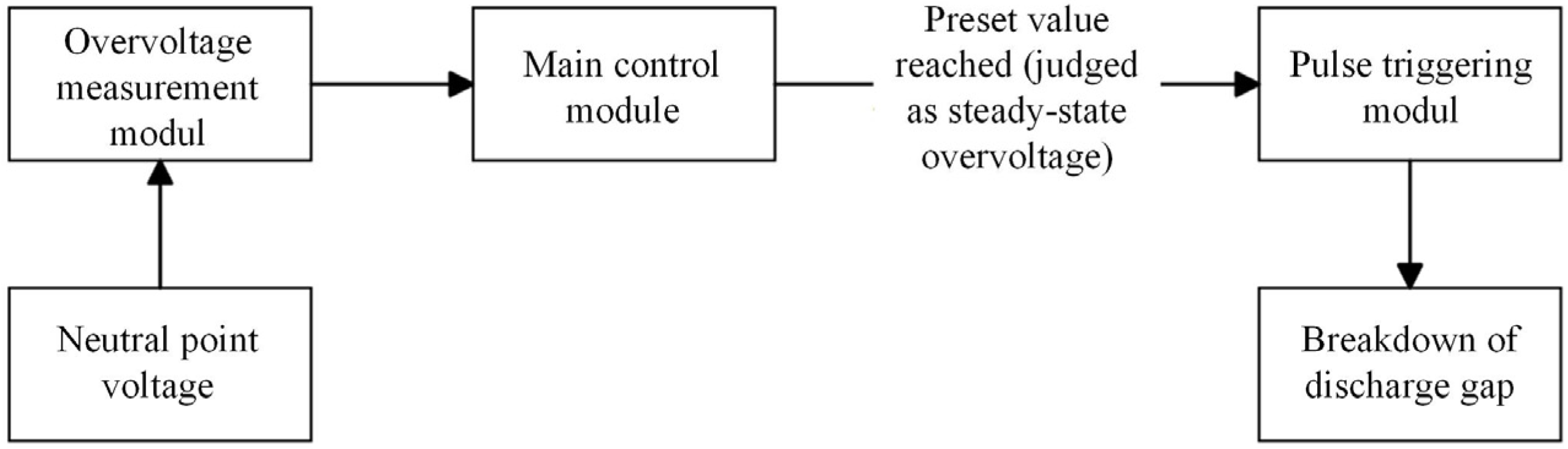
For a transformer neutral point protection device that utilizes a pulse-triggered discharge mechanism, when an overvoltage occurs at the transformer neutral point, the overvoltage measurement and identification module determines the type of overvoltage. The classification is based on the duration and magnitude of the overvoltage acting on the neutral point. If the overvoltage is identified as a steady-state overvoltage, the main control module activates the pulse-triggering device to actively initiate gap breakdown. This subsequently triggers secondary relay protection to isolate the transformer, thereby protecting the neutral point insulation and the surge arrester. The complete decision and protection logic outlined above is illustrated in Figure 5. If the overvoltage is identified as a transient overvoltage, the gap does not break down. Instead, the surge arrester operates to protect the transformer neutral point.
Figure 5.
Logic diagram of the pulse-triggered discharge device.
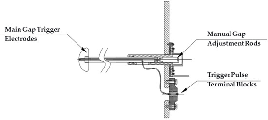
The pulse-triggered discharge device (Figure 6) primarily consists of the following components: active triggering electrodes for the gap (including the triggering electrode and the gap grounding electrode), pulse-triggering leads and terminal blocks, manual gap adjustment rods, and overvoltage detection and pulse generation circuits.
Figure 6.
Pulse-triggered discharge device.
The active triggering electrodes for the gap are located inside the enclosed housing. The triggering electrode is connected to the external pulse control circuit via pulse-triggering leads and terminal blocks. Rotating the gap adjustment rod drives the horizontal movement of the gap grounding electrode, allowing the discharge gap distance to be adjusted according to the different insulation-level requirements of the transformer neutral point.
The pulse generation circuit includes a switching power supply (AC 220 V input, DC 24 V output, 600 W), a high-voltage coil driver module (DC 24 V input, AC 380 V output), and a high-voltage coil (output 61 kV). Upon receiving the pulse-triggered activation signal, the high-voltage coil outputs 61 kV through a high-voltage lead to the triggering electrode, initiating breakdown of the discharge gap.
4. Test Verification
4.1. Prototype Overview and Test Setup
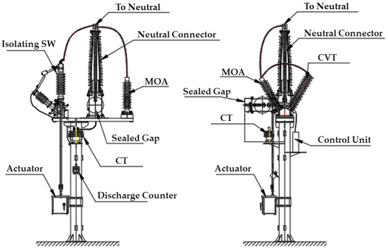
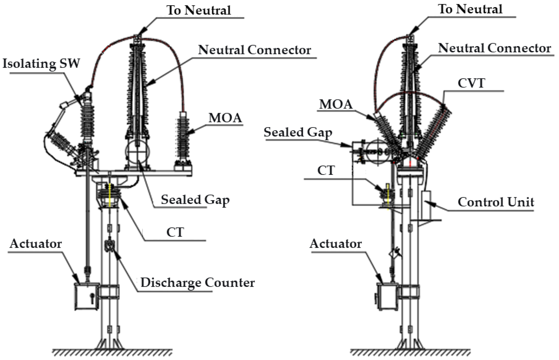
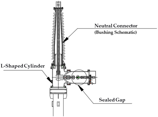
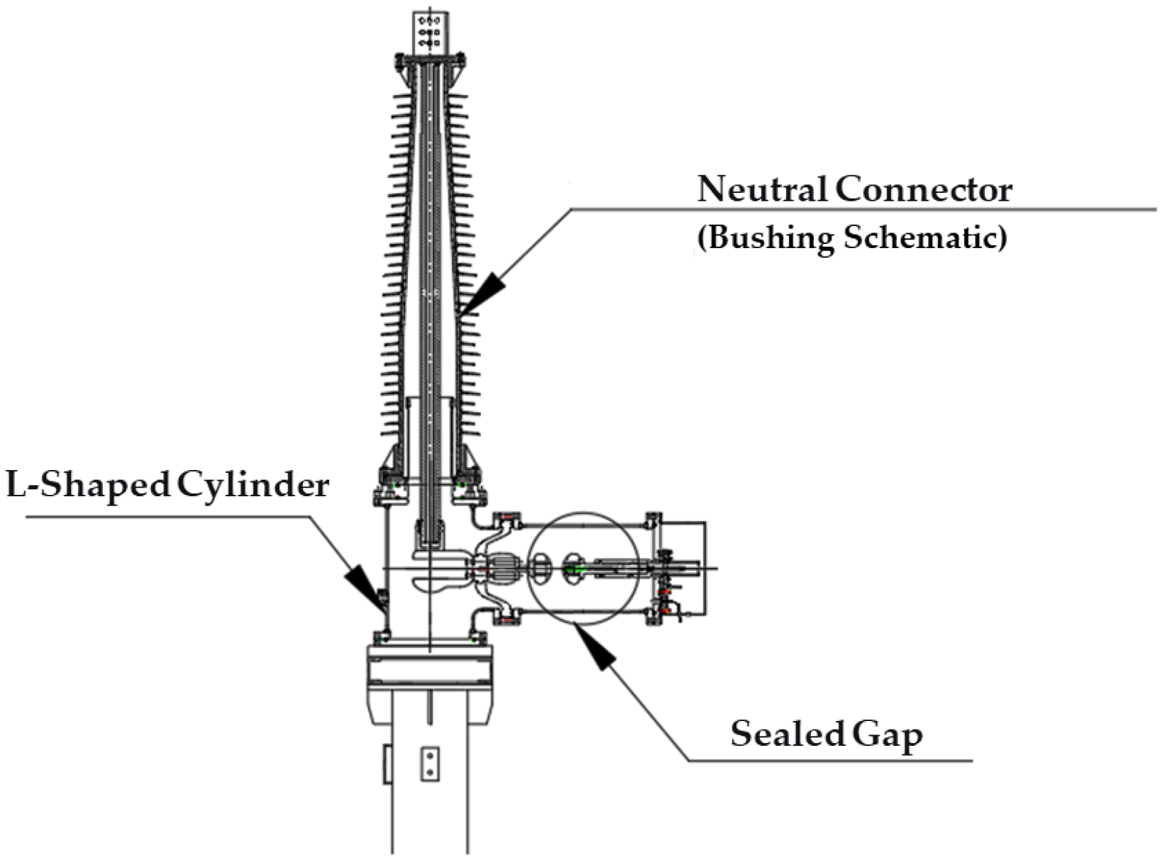
Based on the overall design concept and the design of key components described above, the physical prototype of the intelligent sealed neutral point protection device developed in this study is shown in Figure 7. The overall layout presents a compact and integrated structure, where key units including the maintenance switch, surge arrester, current transformer, and the enclosed discharge gap are clearly arranged on a common mounting frame. The maintenance switch, surge arrester, and enclosed discharge gap are connected in parallel via visible busbars and are directly linked to the transformer neutral point terminal. Notably, the sealed discharge gap chamber adopts a distinctive corner connection structure to interface with the neutral point bushing, the details of which are further illustrated in Figure 8. This corner structure, as shown in Figure 8, features a robust angled conductor and insulator assembly that ensures both mechanical stability and a reliable electrical path from the transformer bushing to the high-voltage terminal of the sealed gap, while also facilitating installation and maintenance access in constrained substation layouts.
Figure 7.
Overall layout diagram of the protection device.
Figure 8.
Structure at the enclosed discharge gap.
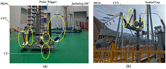
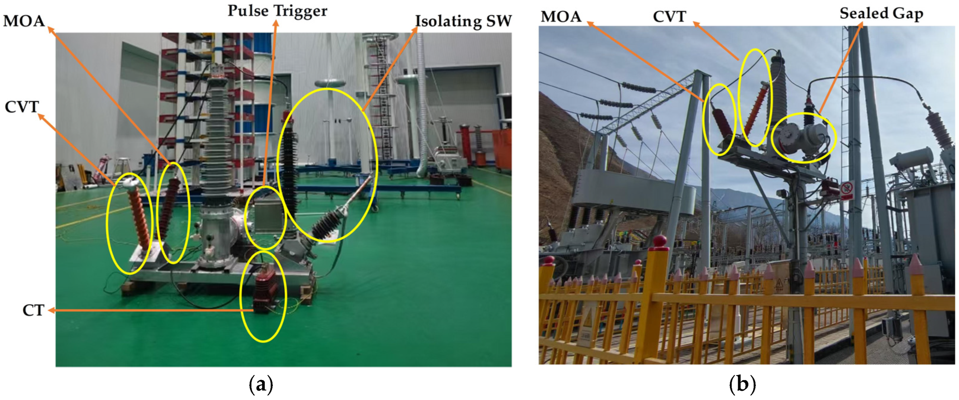
To validate the operational performance and intelligent logic of this prototype, comprehensive on-site commissioning tests were conducted under power-frequency conditions. In the laboratory phase Figure 9a, the prototype’s key subsystems were assembled and accessible for verification. These include the pulse-triggering module, the metal-oxide arrester (MOA), the isolating switch (SW), the capacitive voltage transformer (CVT) for signal acquisition, and the current transformer (CT). The field installation shown in Figure 9b demonstrates the device’s practical integration, where the core sealed discharge gap chamber is mounted alongside the connected MOA and CVT on a dedicated support structure, confirming its adaptability for real-world high-altitude applications. The applied power-frequency voltage levels (e.g., 53 kV, 56.7 kV, 60 kV, 70 kV) simulate the sustained power-frequency overvoltage that may arise at the transformer neutral point under severe single-phase-to-ground fault conditions. These values are determined based on insulation coordination requirements and the protective thresholds set for the neutral point. The core objective was to experimentally verify the dual-criteria control logic (breakdown = (V ≥ Vth) ∧ (t ≥ tth)) implemented within the prototype, under the three critical operational scenarios defined by the design.
Figure 9.
Prototype validation and field installation. (a) The laboratory testing setup. (b) The field installation in a substation.
4.2. Test Results
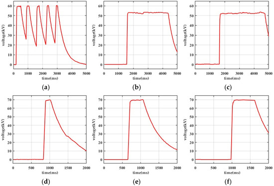
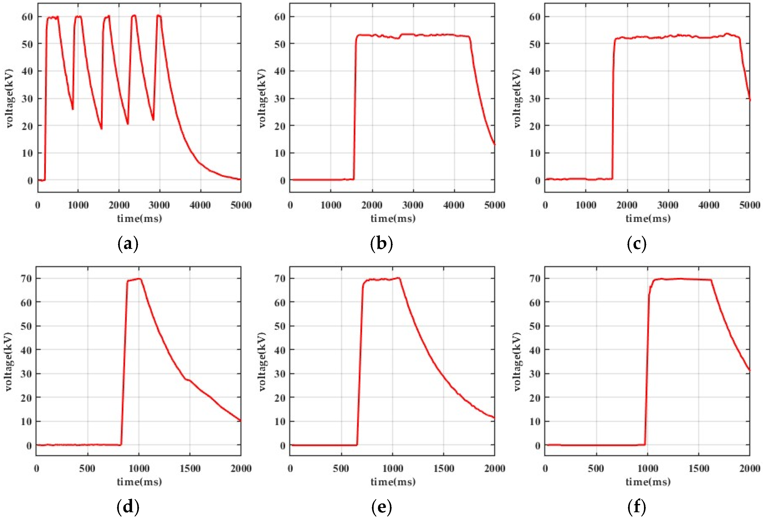
The preset action thresholds were amplitude threshold Vth = 56.7 kV and adjustable duration thresholds tth ranging from 100 ms to 500 ms. The test results for the three defined scenarios are summarized in Table 1 and supported by the corresponding recorded voltage waveforms in Figure 10.
Table 1.
Performance comparison between the proposed intelligent sealed gap and conventional open-type gap protection.
Figure 10.
Recorded neutral point voltage waveforms. (a) Applied voltage: 60 kV; duration: 300 ms and 400 ms (below tth = 500 ms). (b) Applied voltage: 53 kV (below threshold Vth); duration: >3 s (above tth = 300 ms). (c) Applied voltage: 53 kV (below threshold Vth); duration: >3 s (above tth = 500 ms). (d) Applied voltage: 70 kV (exceeds threshold Vth); duration: 100 ms (meets tth = 100 ms). (e) Applied voltage: 70 kV (exceeds threshold Vth); duration: 300 ms (meets tth = 300 ms). (f) Applied voltage: 70 kV (exceeds threshold Vth); duration: 500 ms (meets tth = 500 ms). Repeatability test.
- Figure 10a displays the voltage waveform for Scenario A. The voltage (60 kV) exceeds Vth, but decays before the preset tth (500 ms). As predicted by the logic, no breakdown command was issued, demonstrating immunity to short-duration transients.
- Figure 10b,c display the voltage waveform for Scenario B. The voltage (53 kV) persists for a long duration (>3 s) but remains below Vth. Despite the extended time, no breakdown occurred, confirming stability under low-amplitude, long-duration stress.
- Figure 10d–f display a representative voltage waveform for Scenario C. The voltage equals Vth (70 kV) and is maintained beyond the preset duration, at which point the active breakdown is successfully triggered (the precise moment of trigger command output is marked). This verifies the correct protective operation.
4.3. Discussion and Comparative Analysis
The integrated test results from Table 1 and Figure 10 provide robust experimental evidence that the prototype operates if, and only if, both the amplitude and duration of the neutral point overvoltage simultaneously satisfy the preset conditions. This conclusively validates the intelligent dual-criteria decision logic (breakdown = (V ≥ Vth) ∧ (t ≥ tth)) presented in Section 3.2 [20,21].
To quantitatively contextualize these results against the shortcomings of the existing technology highlighted in the Introduction, a comparative analysis is presented. The proposed device demonstrates clear advancements over conventional open-type gaps in the following key aspects, directly addressing the reliability challenges in high-altitude environments:
- Enhanced Discharge Voltage Stability: unlike conventional gaps whose breakdown voltage is highly susceptible to environmental factors (altitude, pollution, humidity), the sealed N2 environment and fixed geometry of our device ensure stable and reproducible operation. This is evidenced by the consistent performance at the precise thresholds of 56.7 kV and 60 kV in our tests, effectively eliminating environmentally induced maloperation or failure-to-trip [22].
- Superior Transient Overvoltage Response and Selectivity: the active dual-criteria logic represents a fundamental shift from the passive, single-criterion (voltage-only) operation of traditional gaps. By requiring a sustained overvoltage (both V ≥ Vth and t ≥ tth), our device inherently raises its effective withstand voltage for fast transients (e.g., lightning surges) to approximately 3–4 times the steady-state value. This creates a decisive coordination margin with surge arresters, preventing maloperation during transients—a failure mode common in conventional systems where the transient breakdown voltage is fixed at about twice the steady-state value [23]. The successful non-operation in Scenario A (60 kV/300 ms) experimentally confirms this advancement
- Inherent High-Altitude Suitability: the comparative advantage is most pronounced in high-altitude applications. The sealed design directly solves the core environmental vulnerability of open gaps, making the device inherently immune to low pressure, sandstorms, and contamination [24]. This directly fulfills the research objective presented in the Introduction.
In summary, the experimental verification confirms that the integration of environmentally robust hardware (sealed gap) with intelligent software logic (MCU algorithm) successfully mitigates the key failure modes of traditional protection devices [25,26]. The results demonstrate a novel and effective solution that bridges the gap between intelligent control and environmental robustness for transformer neutral point protection in demanding high-altitude settings [27,28].
5. Conclusions
This research developed an intelligent sealed device to solve the unreliable operation of traditional neutral-point protection gaps in high-altitude environments. The solution integrates a nitrogen-sealed discharge gap for environmental immunity with an active control system. The system’s intelligence is derived from a dual-criteria logic, where breakdown is commanded only when both the amplitude and duration of the overvoltage meet or exceed their respective preset thresholds.
Rigorous testing confirmed the device’s operational reliability and selectivity. It remained stable during transient or low-amplitude overvoltages, thus preventing maloperation. Breakdown occurred reliably only under sustained fault conditions where both criteria were satisfied, thereby eliminating the risk of failure-to-trip.
In summary, this work demonstrates that fusing sealed hardware with intelligent control effectively overcomes the key limitations of conventional protection. The proposed device provides a robust and selective solution for enhancing transformer safety in high-altitude power grids.
Author Contributions
W.Y. defined the research objectives and proposed the overall design concept of the device, planned and participated in the equipment development and testing, and is responsible for the reliability of the device; X.L. designed the experimental plan, rigorously revised the technical accuracy, and is responsible for the technical integrity; F.W. designed and fabricated the sealed discharge gap; H.D. designed and fabricated the active breakdown device; Z.Z. assisted in the manufacturing of the device and participated in reliability testing; J.G. wrote the original draft; X.H.: co-conceived the study, developed analytical framework, coordinated team, finalized manuscript, accountable as corresponding author. All authors have read and agreed to the published version of the manuscript.
Funding
This research received no external funding.
Data Availability Statement
The original contributions presented in the study are included in the article, further inquiries can be directed to the corresponding author.
Acknowledgments
The authors would like to thank all those who provided valuable comments and suggestions to improve the quality of this study.
Conflicts of Interest
Author Wen Yan, Xiaohui Li, Fujie Wang, Huifang Dong, Zhongqi Zhao were employed by the Haibei Power Supply Company, State Grid Qinghai Electric Power Company. The remaining authors declare that the research was conducted in the absence of any commercial or financial relationships that could be construed as a potential conflict of interest.
References
- National Energy Administration. DL/T 1848-2018; Technical Specification for Overvoltage Protection of 220 kV and 110 kV Transformer Neutral Points. China Electric Power Press: Beijing, China, 2018. Available online: https://d.wanfangdata.com.cn/standard/DL/T%201848-2018 (accessed on 3 February 2026).
- Standardization Administration of the People’s Republic of China. GB/T 16927.1-2011; High-Voltage Test Techniques—Part 1: General Definitions and Test Requirements. Standards Press of China: Beijing, China, 2011. Available online: https://std.samr.gov.cn/gb/search/gbDetailed?id=3E68F26FAE44386AE06397BE0A0A6860 (accessed on 3 February 2026).
- National Energy Administration. DL/T 620-1997; Overvoltage Protection and Insulation Coordination for AC Electrical Installations. China Electric Power Press: Beijing, China, 1997. Available online: https://d.wanfangdata.com.cn/standard/Ch9TdGFuZGFyZE5ld1NvbHI5UzIwMjYwMTI4MTY1NTM2Eg1ETC9UIDYyMC0xOTk3GghxZXA1bWR1Mw%3D%3D (accessed on 3 February 2026).
- Standardization Administration of the People’s Republic of China. GB/T 50064-2014; Code for Design of Overvoltage Protection and Insulation Coordination for AC Electrical Installations. China Architecture & Building Press: Beijing, China, 2014. Available online: https://d.wanfangdata.com.cn/standard/Ch9TdGFuZGFyZE5ld1NvbHI5UzIwMjYwMTI4MTY1NTM2Eg9HQi9UIDUwMDY0LTIwMTQaCDV2eHBiM2Ri (accessed on 3 February 2026).
- Li, Y.; Liu, J.; Kuang, S.; Xie, W. Overvoltage of 110 kV, 220 kV Transformer Neutral Point and Its Protection Analysis. In Proceedings of the Asia-Pacific Power and Energy Engineering Conference, Shanghai, China, 27–29 March 2012; pp. 1–4. [Google Scholar]
- Helac, V.; Smaka, S.; Grebovic, S.; Oprasic, N. Power Transformer Neutral Point Grounding Methods: Analysis of Fault Characteristics. In Proceedings of the IEEE PES Innovative Smart Grid Technologies Europe (ISGT-Europe), Novi Sad, Serbia, 10–12 October 2022; pp. 1–5. [Google Scholar]
- Liu, M.Z.; Han, R.; Zheng, Y.K.; Yin, Z.; Wu, J.; Wang, H.; Tian, J.J. Breakdown Characteristics and Gap Distance Standardization of Neutral Point Gap in 110 kV and 220 kV Transformers. In Proceedings of the International Conference on Power System Technology: Carbon Neutrality and New Type Power System, Haikou, China, 8–9 December 2021; pp. 2295–2300. [Google Scholar]
- Dai, H.L. Analysis and Protection of 110kV Transformer Neutral Point Overvoltage. Master’s Thesis, Changsha University of Science & Technology, Changsha, China, 2017. Available online: https://d.wanfangdata.com.cn/thesis/Ch1UaGVzaXNOZXdTb2xyOVMyMDI2MDExNzA4NTkxNhIIWTM0NDQ2MjUaCG96enMzMzI1 (accessed on 3 February 2026).
- Wang, J.; Ma, L.T.; Wang, X.T.; Xue, J.; Wang, S.; Zhao, Z.X.; Guo, J. Study on the coordination characteristics of an arrester with parallel gap for 110 kV transformer neutral point. High Volt. Appar. 2020, 56, 228–232+238. [Google Scholar] [CrossRef]
- Zhang, K.Y.; Du, S.Q.; Yuan, D.; Wu, Y.S.; Zhang, F.; Cui, J.J.; Cao, W. Research on the improvement of overvoltage measurement method based on capacitive voltage transformer. Electr. Power Energy 2024, 45, 480–485+501. [Google Scholar]
- IEC 60071-1:2019; Insulation Co-Ordination—Part 1: Definitions, Principles and Rules. International Electrotechnical Commission: Geneva, Switzerland, 2019.
- Wang, P.F. Study of Ball Gap Triggered Discharge Characteristics of Transformer Neutral Point Protection. Master’s Thesis, Harbin University of Science and Technology, Harbin, China, 2023. [Google Scholar] [CrossRef]
- Xu, M.C. Study on Controlled Gap of 110kV Transformer Neutral Point. Master’s Thesis, North China Electric Power University, Beijing, China, 2016. Available online: http://dx.chinadoi.cn/10.7666/d.Y3115145 (accessed on 3 February 2026).
- Wang, J.; Xiao, Q.M.; Chen, X.L.; Wang, H.B.; Wu, Z.Y.; Xu, M.C.; Nie, H.Y.; Zhang, H.Y.; Wei, X.L. Triggering Controlled Discharge Gap Used for Protection of Neutral Point of Power Transformer in 110 kV Power System. J. Harbin Univ. Sci. Technol. 2013, 18, 57–62. Available online: http://dx.chinadoi.cn/10.3969/j.issn.1007-2683.2013.02.011 (accessed on 3 February 2026). (In Chinese)
- Nie, H.; Wang, P.; Chen, Q.; An, Z.; Li, Z. Maximum Working Voltage Range of the Ball Gap Spark Switch. IEEE Access 2024, 12, 183999–184009. [Google Scholar] [CrossRef] [Scilit]
- Gustavsen, B.; Longva, K. Neutral Point Overvoltages in Wye-Wye Connected Distribution Transformer Caused by Lightning Current in Low-Voltage Winding. IEEE Trans. Power Deliv. 2021, 36, 2851–2860. [Google Scholar] [CrossRef] [Scilit]
- Nishikori, Y.; Kojima, S.; Kouno, T. A Study of the Field Utilization Factor and the Maximum Electric Field at Sparkover of the Standard Sphere Gaps. Electr. Eng. Jpn. 2002, 139, 26–32. [Google Scholar] [CrossRef] [Scilit]
- Qiu, Z.; Wu, Z.; Song, Y. Sphere Gap Breakdown Voltage Prediction Based on ISSA Optimized BP Neural Network and Effective Electric Field Feature Set. IEEJ Trans. Electr. Electron. Eng. 2023, 18, 506–514. [Google Scholar] [CrossRef] [Scilit]
- Li, X.; Kang, J.; Li, J.; Zhou, S.; Wang, F.; Ma, G.; Qin, Z.; Dong, H.; Zhang, Y.; Yang, J.; et al. Research on the Design of Enclosed Protective Discharge Gap for Transformer Neutral Point Based on Energy Aggregation Characteristics. J. Phys. Conf. Ser. 2023, 3012, 012032. [Google Scholar] [CrossRef] [Scilit]
- Yang, Z.Y. Research on Analysis of Overvoltage Based on Neutral Point of Power Transformer and Technology of Insulation Protection. Master’s Thesis, Shandong University of Technology, Zibo, China, 2022. [Google Scholar] [CrossRef]
- Liu, C.; He, L.H.; Cui, X.Y.; Li, C.S.; Ma, X.W. Research on zero-sequence protection device arrangement method of neutral point of 110 kV transformer. Power Syst. Prot. 2010, 38, 114–117. Available online: http://dx.chinadoi.cn/10.3969/j.issn.1674-3415.2010.02.028 (accessed on 3 February 2026).
- Jiang, Y.J.; Chen, S.Q.; Zhang, X.; Deng, X.D.; Xu, Y.F.; Meng, H.J. Research and design of an intelligent protection device for 110kV transformer neutral point. Transformer 2020, 57, 42–44+48. [Google Scholar] [CrossRef]
- Han, A.Z. Comprehensive lightning protection measures for power transformers. Transformer 2010, 47, 61–63. Available online: https://d.wanfangdata.com.cn/periodical/CiBQZXJpb2RpY2FsQ0hJU29scjkyMDI2MDIwMjE0MTYxMhIMYnlxMjAxMDAyMDIwGgg1cjZqeTV4Yg%3D%3D (accessed on 3 February 2026).
- Ma, H.; Guo, X.L.; Lu, D.F. Causes and countermeasures for transformer neutral breakdown and adjacent line maloperation due to single-phase grounding. High Volt. Eng. 2001, 27, 58–59. Available online: http://dx.chinadoi.cn/10.3969/j.issn.1003-6520.2001.z1.037 (accessed on 3 February 2026).
- Li, B.J. Study on Parallel Protection of the Air-Water Gap and the Arrester for Neutral Points of Power Transformers. Ph.D. Thesis, Wuhan University, Wuhan, China, 2014. Available online: https://kns.cnki.net/kcms2/article/abstract?v=dKcr_PZ1zcuG83uvbRsFtQPaMX7GM4y07ExPMHNntLJTqclsHnce3B6v5L7hcl2Apg_wjMW0fpIsEb_TVaOrKkMeciI-iVg8hQ9zOGcG-T1OEmK-3mXNM1AQo57NUMSSWQXz-J_uqJmjGpoNk48O_45VHXDyiEo__USIe03xMpoWKX1eT8kyqZhufbD4CZJ-&uniplatform=NZKPT&language=CHS (accessed on 3 February 2026).
- Liu, Z.Y. The Research of Flexible Measures to Limit the Neutral Point Over-Voltage of 110kV–220kV Transformer. Master’s Thesis, North China Electric Power University, Beijing, China, 2017. Available online: http://dx.chinadoi.cn/10.7666/d.Y3263961 (accessed on 3 February 2026).
- Yan, Y.T.; Lu, H.L.; Wang, Y.Z.; Zhu, Z.G.; Chen, R.Z.; Wen, X.S. A new rod-plate-rod combined protection gap for 110 kV transformer neutral point. High Volt. Eng. 2015, 41, 699–704. Available online: http://dx.chinadoi.cn/10.13336/j.1003-6520.hve.2015.02.050 (accessed on 3 February 2026).
- Lin, Y.Z.; Chen, X.J.; Chen, W.J.; Yan, X.L.; Ge, D.; Zhang, C.X.; Ye, K. A protection scheme for ungrounded neutral points of 110 kV and 220 kV power transformers. Power Syst. Technol. 2012, 36, 256–259. Available online: https://d.wanfangdata.com.cn/periodical/CiBQZXJpb2RpY2FsQ0hJU29scjkyMDI2MDIwMjE0MTYxMhINZHdqczIwMTIwNDA0NhoIY3l4ajQzYzg%3D (accessed on 3 February 2026).

Disclaimer/Publisher’s Note: The statements, opinions and data contained in all publications are solely those of the individual author(s) and contributor(s) and not of MDPI and/or the editor(s). MDPI and/or the editor(s) disclaim responsibility for any injury to people or property resulting from any ideas, methods, instructions or products referred to in the content. |
© 2026 by the authors. Licensee MDPI, Basel, Switzerland. This article is an open access article distributed under the terms and conditions of the Creative Commons Attribution (CC BY) license.