


Abstract
This research aims to establish design guidelines for a cantilever triple-layer piezoelectric harvester (CTLPH) with tip mass and tip excitation, operating under resonance conditions. The guideline is derived by combining constitutive equations with Euler–Bernoulli beam theory to identify the effective parameters of the CTLPH and, subsequently, the storage voltage after rectification using a germanium diode bridge. The analysis shows that excitation frequency, piezoelectric coefficients, geometrical dimensions, and the mechanical properties of the layers all significantly influence CTLPH performance. The effects of storage capacitance and excitation frequency were experimentally validated through the design, fabrication, and testing of a prototype. Furthermore, the LTC3588 energy storage module was employed to store the generated charge from resonance motion. An advanced non-contact optical method was employed to determine the bending stiffness of the CTLPH. The output power after the energy storage module was measured across a range of resistive loads at frequencies near the resonance condition (f = 65 Hz). Results demonstrate that both excitation frequency and external resistance affect the maximum harvested power. The developed CTLPH achieved an optimum output power of 46.18 ± 0.98 μW at an external resistance of 3 kΩ, which is sufficient to supply micropower sensors.
1. Introduction
According to Statista, the global number of Internet of Things (IoT) devices is expected to almost triple, increasing from 9.7 billion in 2020 to more than 29 billion by 2030 [1]. Within this ecosystem, connected devices such as wireless sensors alone are projected to reach 125 billion units by 2030. Each sensor typically consumes around 500 μW to transmit collected data to a datalogger, assuming a modest reporting rate of 10 messages per day [2]. Although high-energy-density lithium-ion batteries are competitively priced and widely applied across electronic systems, their replacement or recharging poses significant challenges in certain contexts. For example, in remote and mountainous regions, fire-detection sensors are vital for environmental monitoring and early wildfire warnings, yet replacing or recharging their batteries is often impractical. To overcome these limitations, researchers have explored self-powered modules that utilize smart materials to reduce dependence on conventional batteries [3,4]. In response to the growing demand for sustainable alternatives, a wide range of energy-harvesting technologies has been developed to convert ambient energy into electricity, including miniature solar cells [5], electrostatic and electromagnetic harvesters [6], reverse electrowetting devices [7], and systems based on smart materials [8,9].
Nevertheless, each energy-harvesting approach has its own limitations. For example, solar harvesters are ineffective during overcast conditions or at night [10,11] while electrostatic devices are constrained by their inherently low energy density [12]. Most electromagnetic harvesters require large coils, which restrict miniaturization [13], and reverse electrowetting systems demand complex and costly fabrication processes [14]. Among smart materials, piezoelectrics have attracted considerable attention, having been employed as actuators, vibration absorbers, sensors, and lightweight structural components [15], in addition to their role as energy harvesters [16,17]. Although piezoelectric harvesters offer high energy density, their operational lifespan remains limited [18,19], primarily due to the formation of microstructural cracks [20]. Recent studies have shown that multilayer designs provide a promising route to enhance durability and improve output voltage, thereby extending the practical utility of piezoelectric harvesters [21].
Piezoelectric harvesters can be designed for non-resonant applications, such as biomedical implants [22,23,24], or for resonant applications [2,25]. Numerous studies have developed mathematical models to predict the output voltage and power of multilayer piezoelectric structures across a wide range of frequencies. For instance, Smits et al. [26] formulated the constitutive equations for bimorph piezoelectric devices with both series and parallel electrical branch configurations. DeVoe et al. proposed a model to predict the static deflection and generate voltage of piezoelectric cantilever beams; however, this approach increases complexity due to the requirement of matrix inversion [27]. Weinburg offered a simplified model but neglected the effect of the electromechanical coupling coefficient, which was justified at the time because most Lead Zirconate Titanate (PZT) materials exhibited low coupling coefficients of only around 12% [28]. Wang et al. calculated the tip deflection of cantilever triple-layer actuators with sequential electrode connections using internal energy and constitutive equations [29]. Tadmor et al. subsequently refined the Weinburg and Wang models to incorporate the influence of larger electromechanical coupling coefficients enabled by newer materials (e.g., K31 = 0.38 for PZT-5H) [30].
The choice of substrate in piezoelectric energy harvesters plays a pivotal role in determining their output performance. Previous studies have examined various substrate materials for different applications. For example, Lu et al. [31] and Cao et al. [32] developed multilayer piezoelectric harvesters incorporating carbon and glass fiber substrates, demonstrating their suitability for base-excitation scenarios. Additionally, the performance of harvesters employing carbon fiber substrates [33], aluminum substrate [34], and silicon substrate [33] has been investigated individually under diverse operating conditions. In the present study, we aim to conduct a systematic evaluation of these substrates using identical excitation methods. This approach will enable a direct comparison and facilitate the identification of the most suitable substrate for optimized energy harvesting performance under uniform experimental conditions.
Depending on the application, kinetic energy harvesters are classified by their excitation method: tip excitation or base excitation. Each method can be implemented with or without a tip mass. Many research studies have explored tip mass effects to enhance bandwidth and output in piezoelectric energy harvesters. For example, Rezaei et al. demonstrated that adding a tip mass tunes resonance frequency and increases voltage, while nonlinear restoring forces broaden the operational bandwidth for random excitations [35]. Similarly, Upendra et al. investigated geometric nonlinearity and tip excitation for broadband harvesting [36], and Xia et al. [37] analyzed hybrid parametric and external excitations, showing that tip mass reduces initiation thresholds and shifts frequency-response curves. Tang and Wang further highlighted the critical role of tip mass offset and dynamic magnifiers in improving accuracy and power output [38]. Despite these advances, no comprehensive model addresses combined tip excitation and tip mass underscoring the necessity for an integrated approach to optimize energy harvesting performance. A design guideline for cantilever triple-layer piezoelectric harvesters (CTLPHs) with tip excitation and a tip mass operating at a non-resonant frequency was proposed [39]. However, to the best of our knowledge, no clear design procedure has yet been reported for CTLPHs with tip excitation and a tip mass operating at a resonant frequency.
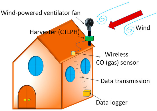
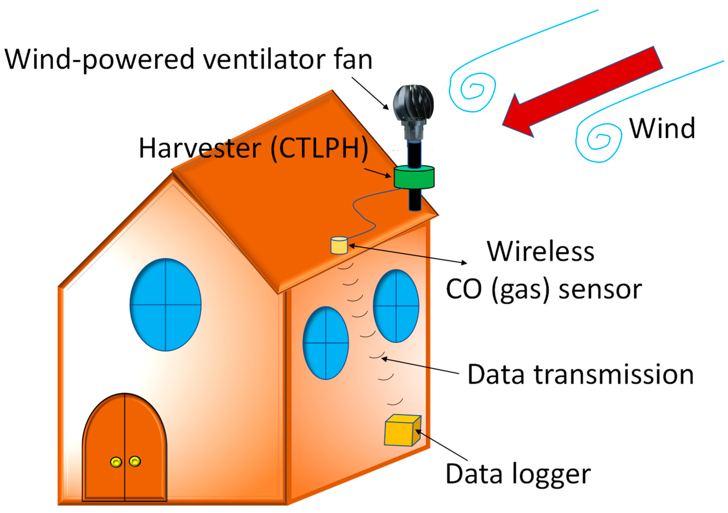
This paper aims to provide a comprehensive guideline for designing a CTLPH operating at its resonance frequency, with tip excitation and tip mass. Section 2 presents the combination of constitutive equations and Euler–Bernoulli beam theory to develop a mathematical model for the harvester. The model captures the dependence of both the natural frequency and the generated voltage on the tip mass-to-beam mass ratio, geometrical dimensions, and the mechanical properties of the constituent layers. Based on the simulation results, an appropriate substrate is selected to be excited at its first natural frequency (i.e., resonance) by low-frequency excitation. Section 3 details the simulations conducted using the model developed in Section 2. Guided by these findings, a CTLPH prototype was fabricated. The bending stiffness of the prototype was measured experimentally using an optical method with a laser displacement sensor. Section 4 presents the verification of the mathematical model using these experimental data. Additionally, the performance of the energy storage module (LTC 3588) and the influence of resistance loads and excitation frequencies on its operation are investigated. Finally, the harvested power of the CTLPH prototype under various resistance loads and frequencies is analyzed to demonstrate the effectiveness of the proposed harvester for powering low-power IoT monitoring devices, as illustrated in Figure 1.
Figure 1.
A wind-driven ventilator fan used as an energy source for wireless IoT monitoring sensors and condition-monitoring systems.
2. Theoretical Analysis
2.1. Assumptions of Dynamic Behavior
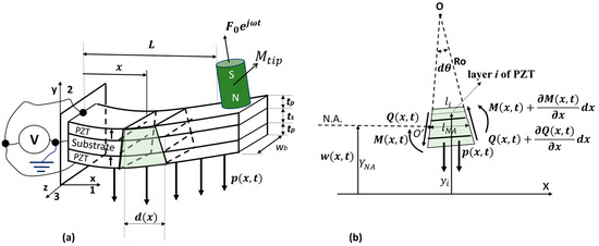
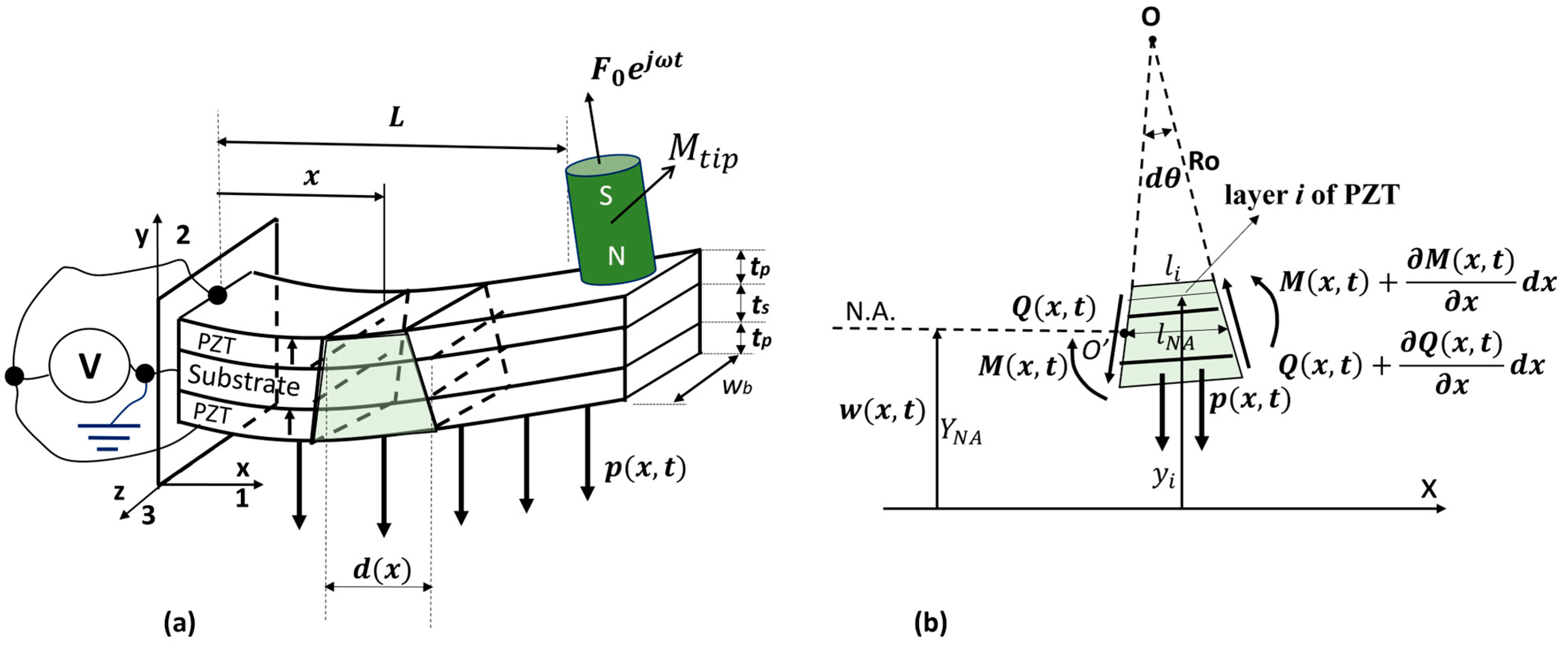
Based on the assumption described in [39], this work presents the design, fabrication, and modeling of a symmetrical CTLPH equipped with a tip mass to enable resonant operation. The CTLPH presented in Figure 2a can be modeled by the Euler–Bernoulli beam with effective length (L) and width (wb). As shown in Figure 2b, the relationship between the applied bending moment M(x,t), and the resulting deformation w(x,t) is given by (1).
where the superscript ‘s’ represents the substrate elastic elements, and d31, ts, are the transverse piezoelectric coefficient, thickness, strain, stress, and elastic modulus of the substrate layer, and superscript ‘p’ represents piezoelectric layer. Furthermore, E3 is the electric field, and Ro(x) is the curvature radius of the neutral plane at position x. As explained in [39], the applied forces and moments acting on an infinitesimal beam element induce deflection. The layers are assumed to be perfectly bonded, ensuring no delamination during vibration. Summing the forces in the y-direction for the differential element yields the acceleration Equation (2).
Figure 2.
(a) Schematic of a CTLPH undergoing transverse vibration. (b) Free-body diagram of an infinitesimal element [40].
On the left side of (2), Q(x,t) is the shear force, and p(x,t) is the externally applied force on the element per unit length. The resultant force on the left causes the inertial force on the right side of the equation. By ignoring the rotary inertia of the element, the resultant moment about the z-axis, about point O on the element, can be obtained by (3)
simplifying (3) yields (4).
By neglection (dx)2 and substituting (1) in (4), the relationship between shear force and change in moment of inertia is presented by (5).
Substituting (5) in (2) yields (6).
Simplification of (6) is presented in (7)
To calculate the natural frequency of the triple-layer beam, it is required to have free vibration. In other words, the external force of p(x,t) = 0, and we assume a constant EI(x) = EI and A(x) = A. Therefore, (7) can be presented in the simplified form of (8).
If the mass of the beam per unit length is equal to U, the free vibration equation can be governed by (9).
Separation of variables can be a suitable solution for a simple harmonic motion of the partial differential Equation (19) which can be presented in (20).
Substituting (10) in (9) causes a fourth-order differential of (11). To solve this differential equation, four boundary conditions are required. For a cantilever beam with a tip mass, four conditions of (12) to (15) need to be satisfied—two conditions at x = 0 and two conditions at x = L.
By substitution of (20) in (21)–(25), the new forms can be deduced by (26)–(30).
The general solution of (26) can be in the form of or in the form of (31).
The four boundary conditions are used to determine the value of and only three of the coefficients in (31).
By substituting (32)–(34) to (31), the general solution can be presented in
It is obvious that, to identify one of the unknown values in (25), we need to substitute (25) in the last boundary condition obtained in (20).
The equation of (26) with only one unknown value of is called a characteristic equation. The resonance frequency can be solved by a graphical method to specify the By defining as the ratio of tip mass to beam mass,, (26) can be presented in a simplified form of (27).
By solving (27), various roots of the characteristic equation can be determined as that are related to the natural frequencies of the triple-layer piezoelectric beam by (28).
It is required to mention that mbeam = UL. To find the displacement at any position like x, the last boundary condition, Equation (20), should be satisfied. By substituting (25) in (20) and after simplifying, can be calculated by (29).
where NN and MM are two variables as a function of energizing frequency:
As shown in (28), the natural frequency depends on the bending stiffness (EI). In the parallel connection, the relationship between the electric field (E3) and applied voltage (V) can be found in (32).
For open circuit conditions (), the bending stiffness can be deduced from (1). Then EI can be simplified by (33).
where and are the elastic modulus and thickness ratio of the elastic layer to the piezoelectric layer, respectively.
2.2. Generated Voltage and Power
For the harvester with no externally applied voltage, ( = 0), and in the presence of external tip force, the combination of electromechanical equations and strain of the piezoelectric layer presented in [39] yields
where and are the electric displacement and electric field across electrodes in z or 3-direction. After substituting y by its avergage value, and employing (1)
To total charge, q, collected on the electrodes with area S, can be calculated by (36).
Substituting (10) in (36) leads to
The explicit relationship for the generated charge (q) in each frequency ( can be presented as
Considering as the surface of the electrode, S, the generated voltage across the electrodes of the harvester with a parallel connection can be calculated as
Therefore, the output power across the connected external resistive load, , can be computed as
3. Simulation Result Analysis
3.1. Characteristic Equation
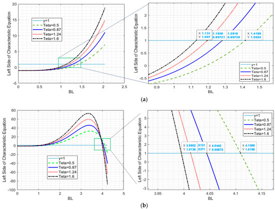
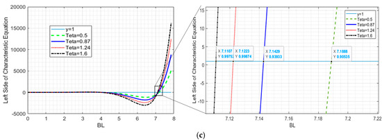
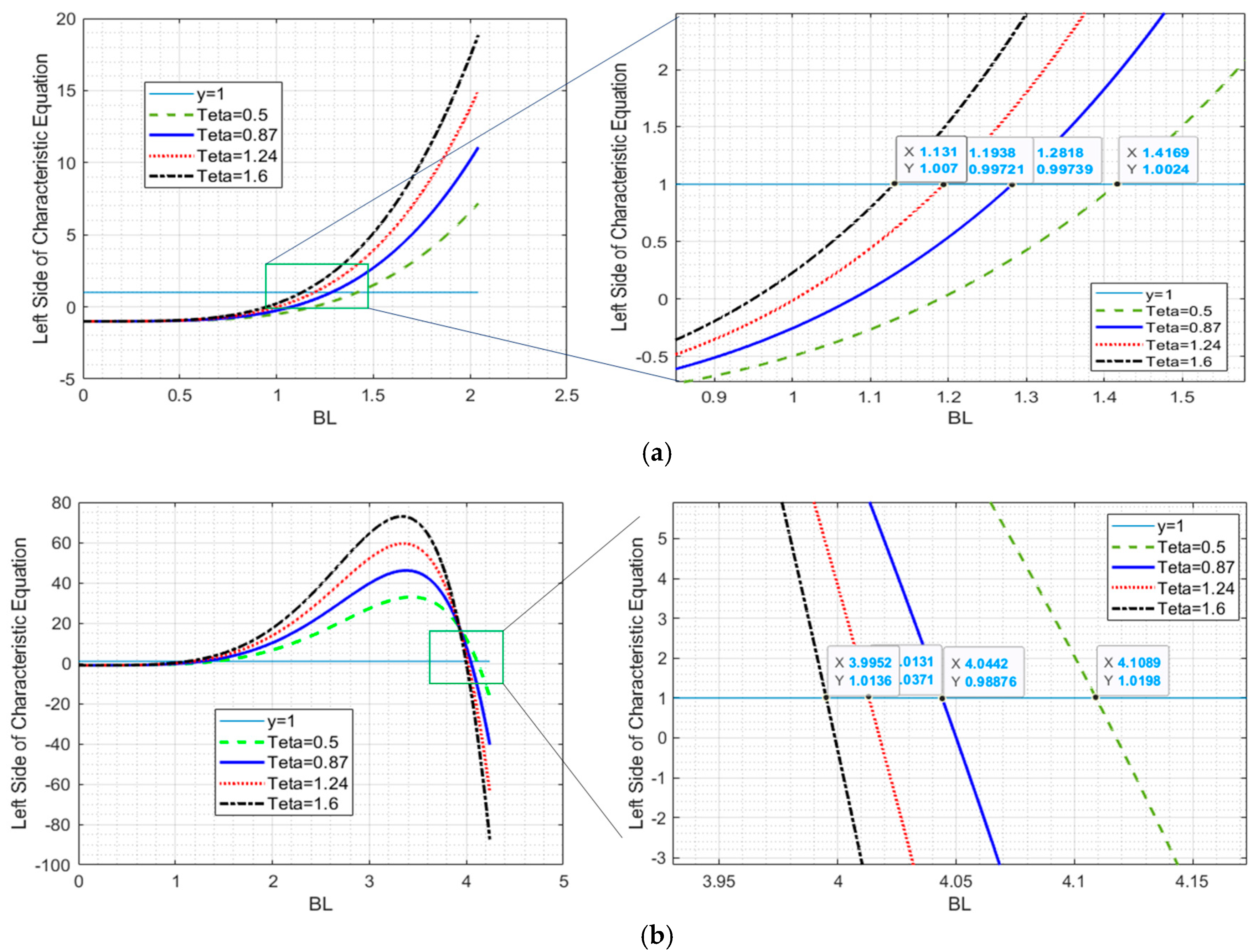
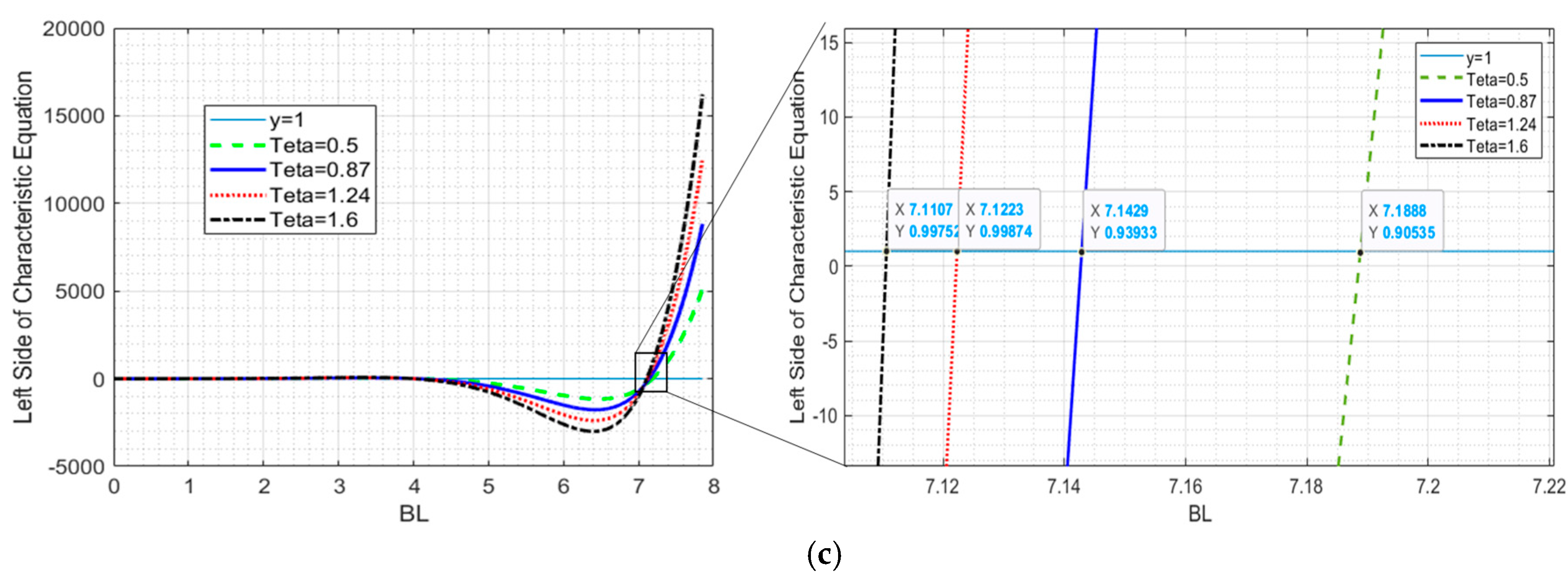
Equation (38) predicts the effect of natural frequency, material properties (i.e., elastic modulus, electromechanical coupling coefficient, and density), and geometrical dimensions (i.e., the thickness of layers and length of the beam) on the generated charge by the harvester. Meanwhile, the effect of mass ratio () on the of the harvester can be calculated by (27). The effect of mass ratio on the is shown in Figure 3a, Figure 3b, and Figure 3c, respectively. The mass ratio was selected as 0.5, 0.87, 1.24, and 1.6. A higher mass ratio causes lower natural frequencies in the first three mode shapes. Since a higher mass ratio needs more space, the lower mass ratio was selected for the rest of the analysis. Table 1 summarizes the effect of the mass ratio. In practical applications, normally the first mode shape is used to gain maximum charge and voltage.
Figure 3.
Effect of mass ratio, tip-mass to the beam mass, on the natural frequencies (a) (b) (c) .
Table 1.
Effect of ratio of tip-mass to the beam mass on the natural frequencies.
3.2. Material and Geometrical Effect of Substrate
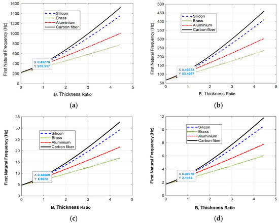
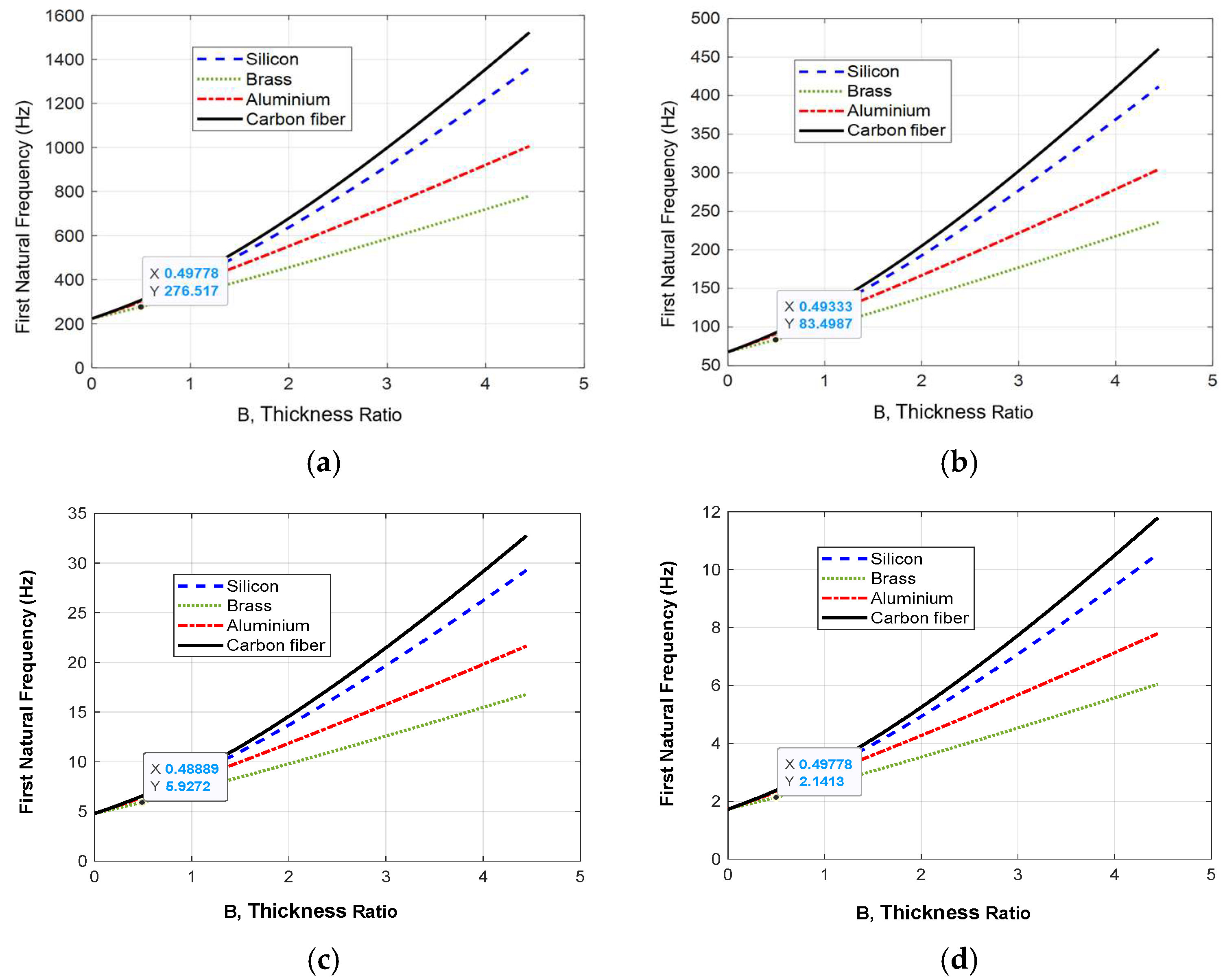
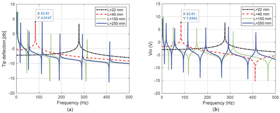
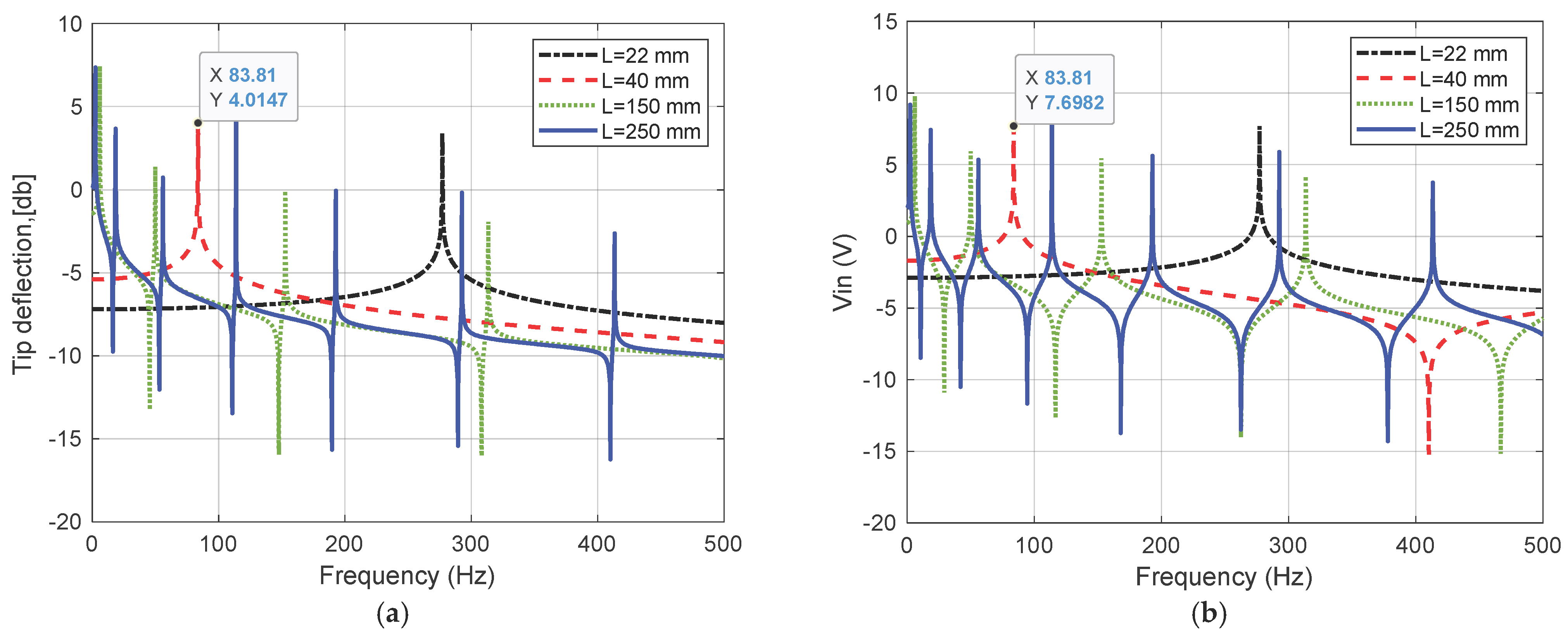
From Equation (38), it is evident that the thickness of the layers, the length, and the Young’s modulus play a critical role in determining the generated charge and output power. Figure 4 illustrates the influence of key geometrical parameters, including the thickness ratio between the substrate and piezoelectric layers , length of the harvester, and the ratio of the elastic moduli of the substrate and piezoelectric material were investigated. The thickness of the piezoelectric (PZT-5H) layer was fixed at 0.225 mm, with an electromechanical coupling factor K31 = 0.38. Reducing the substrate thickness proved effective in lowering the first natural frequency; however, excessively thin substrates compromise the structural integrity of the harvester. Four different substrate materials (i.e., carbon fiber, brass, aluminum, and silicon) were selected for investigation. As illustrated in Figure 4, with equal substrate thickness, carbon fiber and brass exhibited the highest and lowest natural frequencies, respectively. In other words, among all harvesters with identical piezoelectric layer thicknesses, the brass-substrate configuration reaches resonance at the lowest excitation frequency. The effect of harvester length on natural frequency is also presented in Figure 4a–d. The analyzed lengths were 22, 40, 150, and 250 mm. Across all lengths, brass consistently produced the lowest natural frequency. The influence of harvester length on tip deflection and storage voltage (Vin) is highlighted in Figure 5a and Figure 5b, respectively. Results clearly indicate that shorter CTLPHs yield higher natural frequencies, while higher voltages can be achieved under resonance conditions.
Figure 4.
Effect of beam’s length on the first natural frequencies; , tp = 0.225 mm; w = 0.01 mm (a) L = 22 mm; (b) L = 40 mm; (c) L = 150 mm; (d) L = 250 mm.
Figure 5.
Effect of beam’s length and frequency on (a) tip deflection with brass substrate; (b) generated voltage θ , tp = 0.225 mm; ts = 0.11 mm.
Based on the simulation results, a Brass substrate with tip to beam mass ratio of 0.5 ( and thickness ratio of 0.49 is selected for fabrication of the CTLPH prototype and the experimental validation of the model.
4. Experimental Results
4.1. Principle of Operation
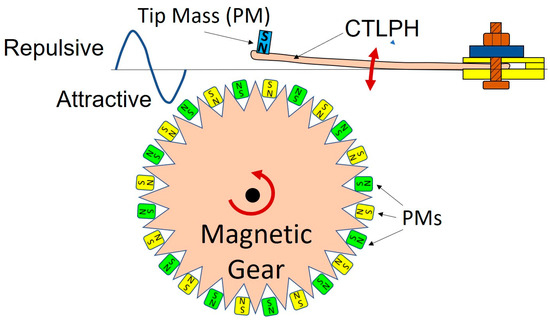
The schematic structure of the developed energy conversion device, comprising the CTLPH and its excitation mechanism, is illustrated in Figure 6. The CTLPH consists of an elastic substrate sandwiched between two piezoelectric layers, with a tip mass, and is clamped at its base. The excitation mechanism is an acrylic gear fitted with magnets on its teeth to generate an oscillating tip force. The tip mass of the cantilever beam is a cylindrical permanent magnet. The gear, with a diameter of 300 mm and teeth spaced 3 mm apart, was fabricated from a 5 mm-thick acrylic plate. A total of 120 cubic NdFeB permanent magnets (3 × 3 × 3 mm, grade N35) were attached to the gear teeth. The polarity of the permanent magnets on both the gear teeth and the CTLPH was arranged to produce alternating repulsive and attractive forces, thereby inducing periodic excitation. The rotational motion of the magnetic gear results in bending deflection at the CTLPH tip, which in turn generates charge accumulation on the electrodes and induces a voltage across them.
Figure 6.
Principle of CTLPH and excitation mechanism, rotary magnetic gear.
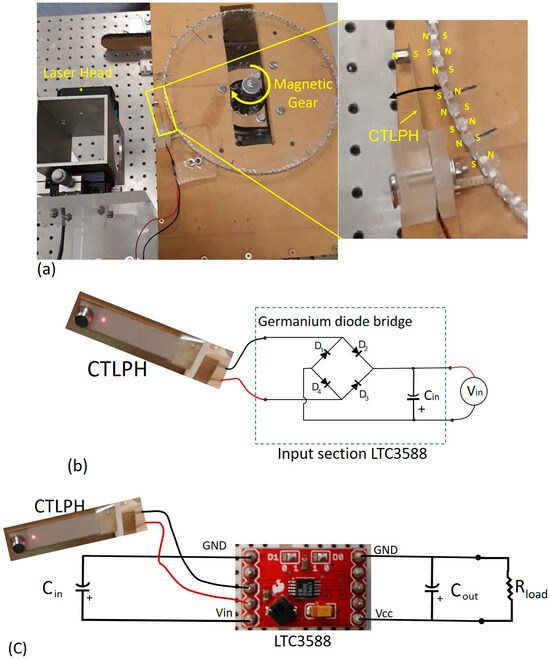
In other words, the oscillation frequency of the CTLPH is 60 times higher than the rotational frequency of the magnetic gear. The gear’s rotational speed is controlled by a DC rotary motor, allowing the oscillation frequency at the tip to be varied between 10 and 122 Hz through precise regulation of the motor’s supply voltage. It is necessary to add that the magnets employed in the setup are of the same grade (N35), ensuring uniform magnetic field strength. As shown in Figure 7a, the vibration amplitude at the beam tip was measured using a highly sensitive laser displacement sensor (model HK-052) to determine the bending stiffness of the CTLPH. To verify charge generation, a Germanium diode bridge rectifier was employed (Figure 7b). The harvested voltage was then stored using the LTC3588 energy storage module (Figure 7c). Data acquisition was performed with a National Instruments BNC-2110 card. The fabricated CTLPH consists of a brass substrate strip (ts = 0.11 mm, Es= 110 GPa) sandwiched between two PZT-5H layers (ts = 0.225 mm, Ep = 53 GPa). The material constants of PZH-5H are d31 = −270 × 10−12 C/N, k31 = 0.38, . The complete specifications of the employed CTLPH are summarized in Table 2.
Figure 7.
Experimental setup. (a) Driving and laser displacement setup. (b) Germanium diode bridge (1N34A) of the input section of LTC3588. (c) Connection of the energy regulator module, LTC3588 [41].
Table 2.
Experimental parameters of the CTLPH sample.
4.2. Bending Stiffness
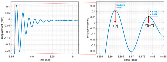
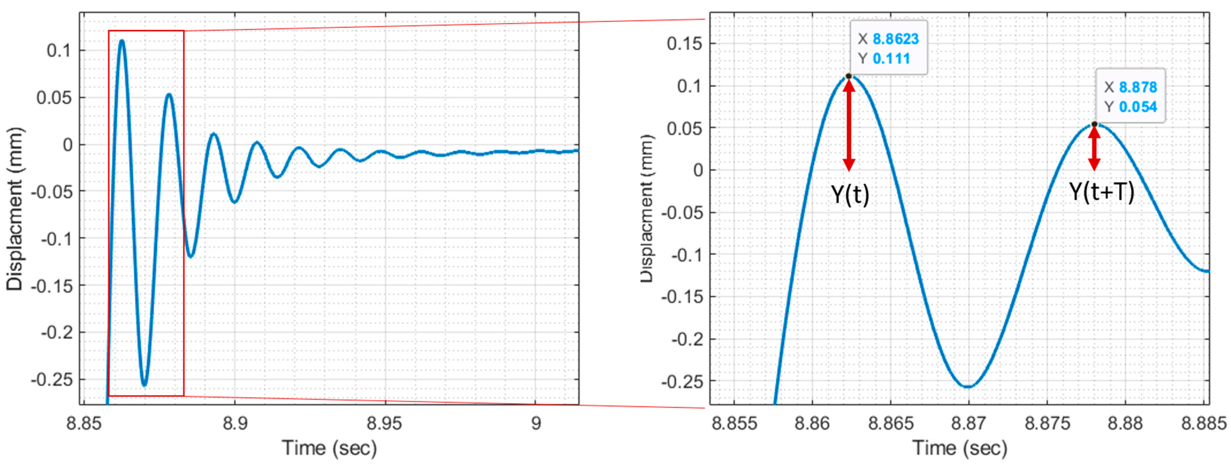
Kinetic harvesters achieve their highest output power at the resonant frequency, where vibration amplitude is maximized. As shown in (38), the bending stiffness (EI) has a significant influence on natural frequency. Therefore, calculating the bending stiffness using (43) is a practical approach for estimating natural frequencies. To validate the analytical relationship in (43), the experimental setup illustrated in Figure 7a was used to measure the tip vibration amplitude of the CTLPH under free vibration. As shown in decrement [9], indicated by , which is
In Figure 8, the damped frequency vibration can be deduced from the concept of logarithms. From Figure 8, it can be measured that the period of damped vibration is Td = 0.0157 sthat leads to damped frequency of 63.69 Hz for the harvester. In addition, the external damping ratio () of the beam can be found in (52).
Figure 8.
Tip displacement at free vibration with Brass substrate; , tp = 0.225 mm; ts = 0.11 mm.
From Equations (41) and (42), the damping ratio of the harvester is calculated to be 0.32. Owing to this relatively small damping ratio, the damped frequency of the harvester is nearly identical to its first natural frequency ( and can be calculated as:
After measuring the first natural frequency ( = 67.22 Hz) using the bending stiffness can be calculated by (38). The specifications of different layers of the CTLPH sample are presented in Table 2. From Table 1, the value of is 1.416 for the brass substrate with . Substituting the values available in Table 2 in (38) leads to (54), presenting the bending stiffness of the CTLPH:
4.3. Tip Displacement and Applied Tip Force
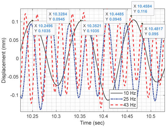
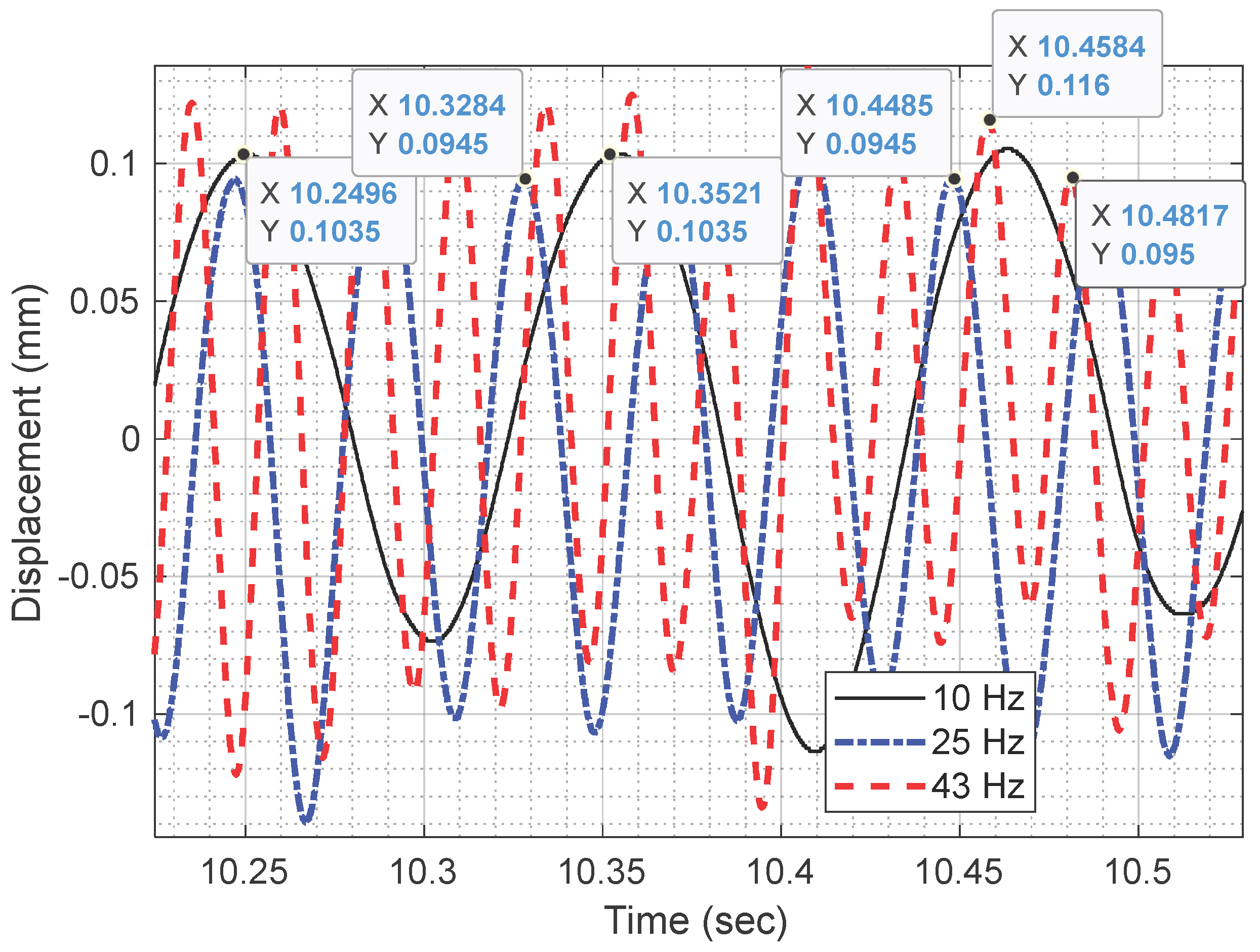
Figure 9 illustrates the tip deflection of the CTLPH when the magnetic gear operates at non-resonant frequencies (10, 25, and 43 Hz). The measured amplitude is approximately 0.1 mm, with a maximum displacement of ±0.11 mm (peak), corresponding to a peak-to-peak value of 0.22 mm. Considering the beam length of 40 mm (Table 2), the deflection ratio is about 0.28%, well below the 1% threshold for small-deflection assumptions. The waveform remains sinusoidal without evidence of geometric nonlinearity, confirming the suitability of linear beam theory and classical harmonic approximation for modeling in this study. In other words, the well-known relationship between tip deflection and tip force can be confirmed in Equation (45) [40]:
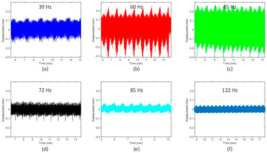
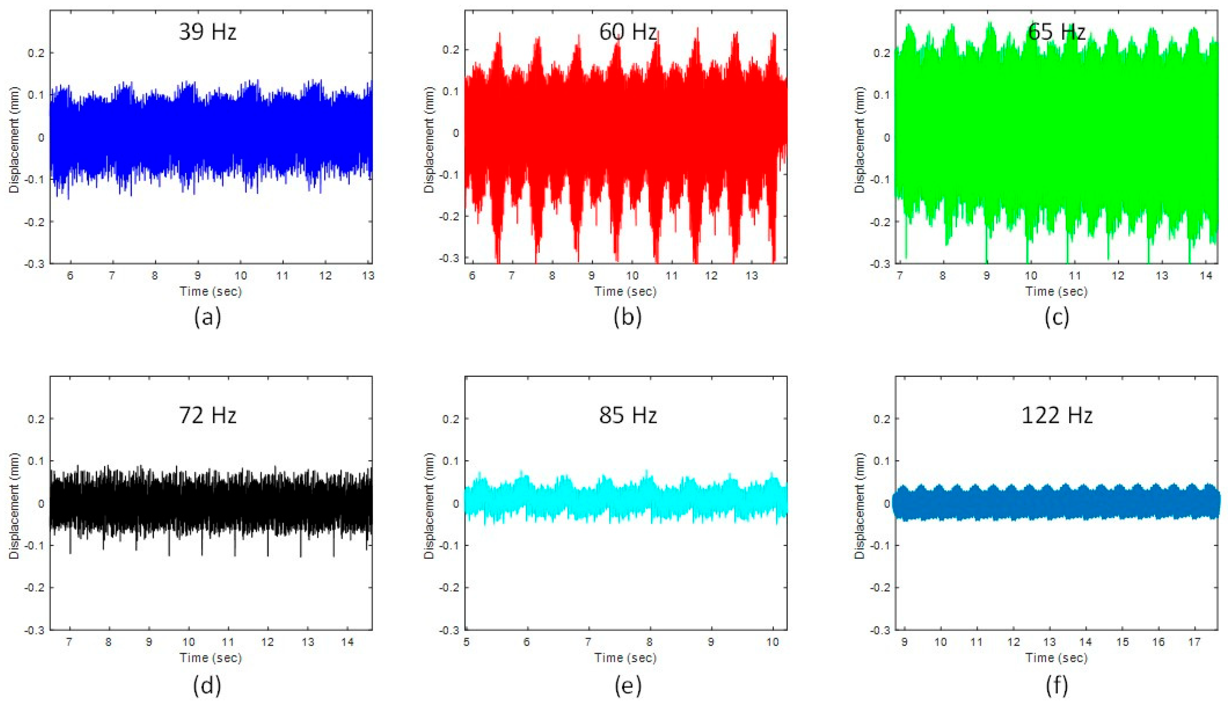
By increasing the rotating speed of the magnetic gear and approaching the resonance frequency the beating effect can be observed (Figure 10a). Figure 10b shows that the amplitude of the tip deflection close to the resonance frequency reaches 0.25 mm. In the next step, by substituting the value of bending stiffness measured from Section 4.2 and measured tip deflection in resonance and close to the resonance frequencies in Equation (44), the applied force can be calculated without any mechanical contact. By replacing the bending stiffness value (EI = 0.0043 N.m2) and maximum tip deflection for a non-resonant condition and in (45), the maximum applied tip force can be specified as 20 and 50 mN for non-resonance and resonance conditions.
Figure 9.
Displacement vs. time in non-resonance frequencies: (10–43 Hz).
Figure 10.
Displacement vs. time in different frequencies: (a) 39 Hz; (b) 60 Hz; (c) 65 Hz; (d) 72 Hz; (e) 85 Hz; (f) 122 Hz.
Figure 10 illustrates the tip deflection of the CTLPH as the magnetic gear rotates at various frequencies (39, 60, 65, 72, 85, and 122 Hz). As the rotational speed of the magnetic gear increases and approaches the resonance frequency, a beating effect becomes evident. Figure 10b,c show that, near the resonance frequency, the tip deflection amplitude reaches approximately 0.25 mm. In contrast, at non-resonant frequencies (f < 60 Hz and f > 70 Hz) the amplitude is significantly lower, ranging from 0.05 to 0.1 mm, as shown in Figure 10a,d–f.
4.4. Rectified Input Voltage
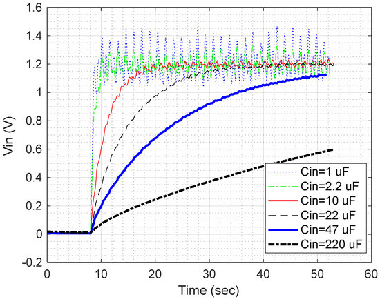
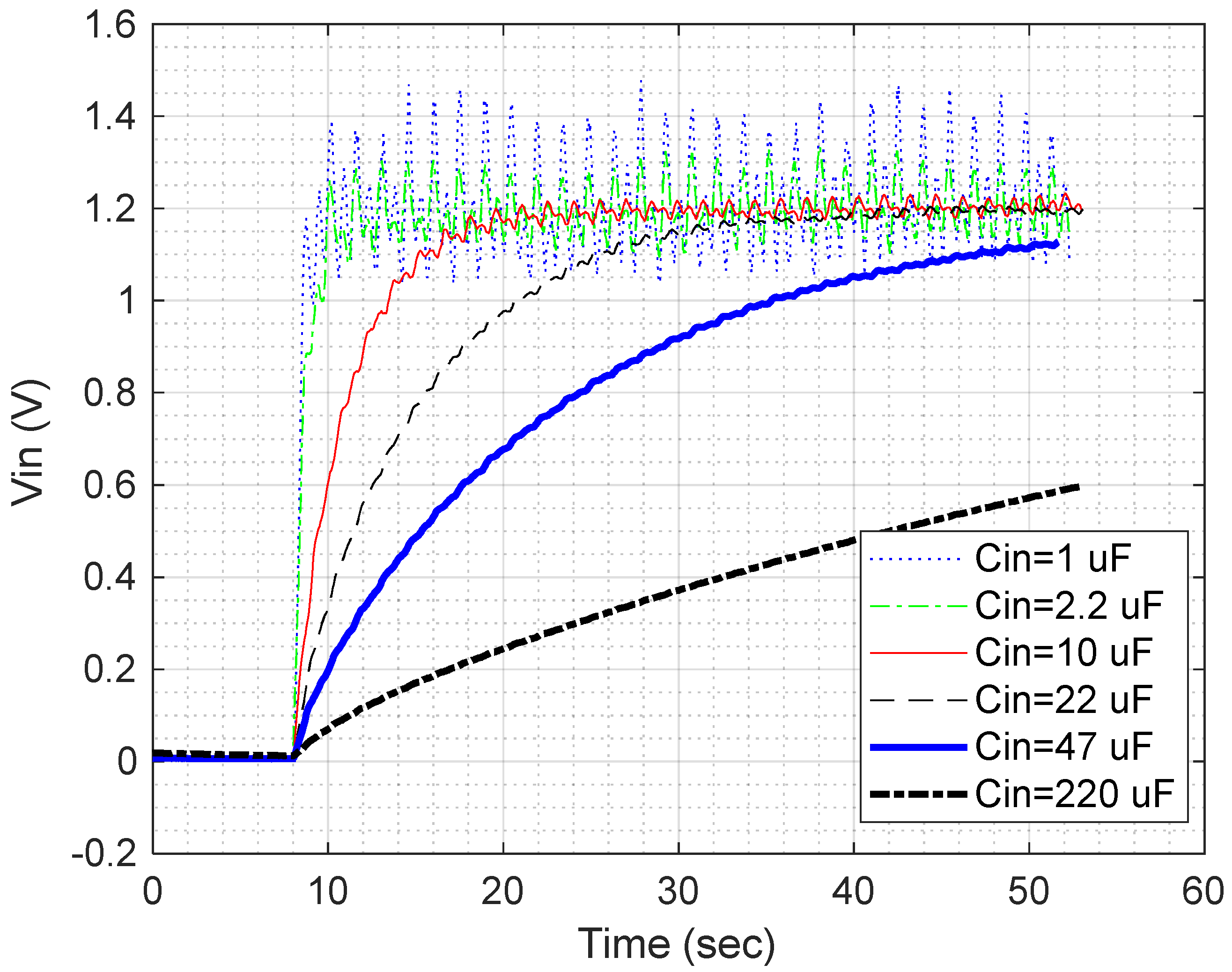
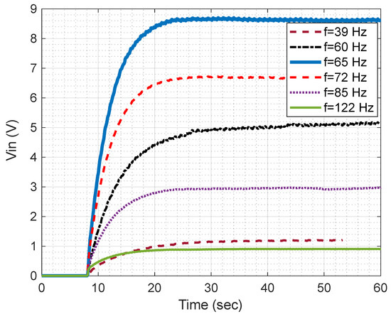
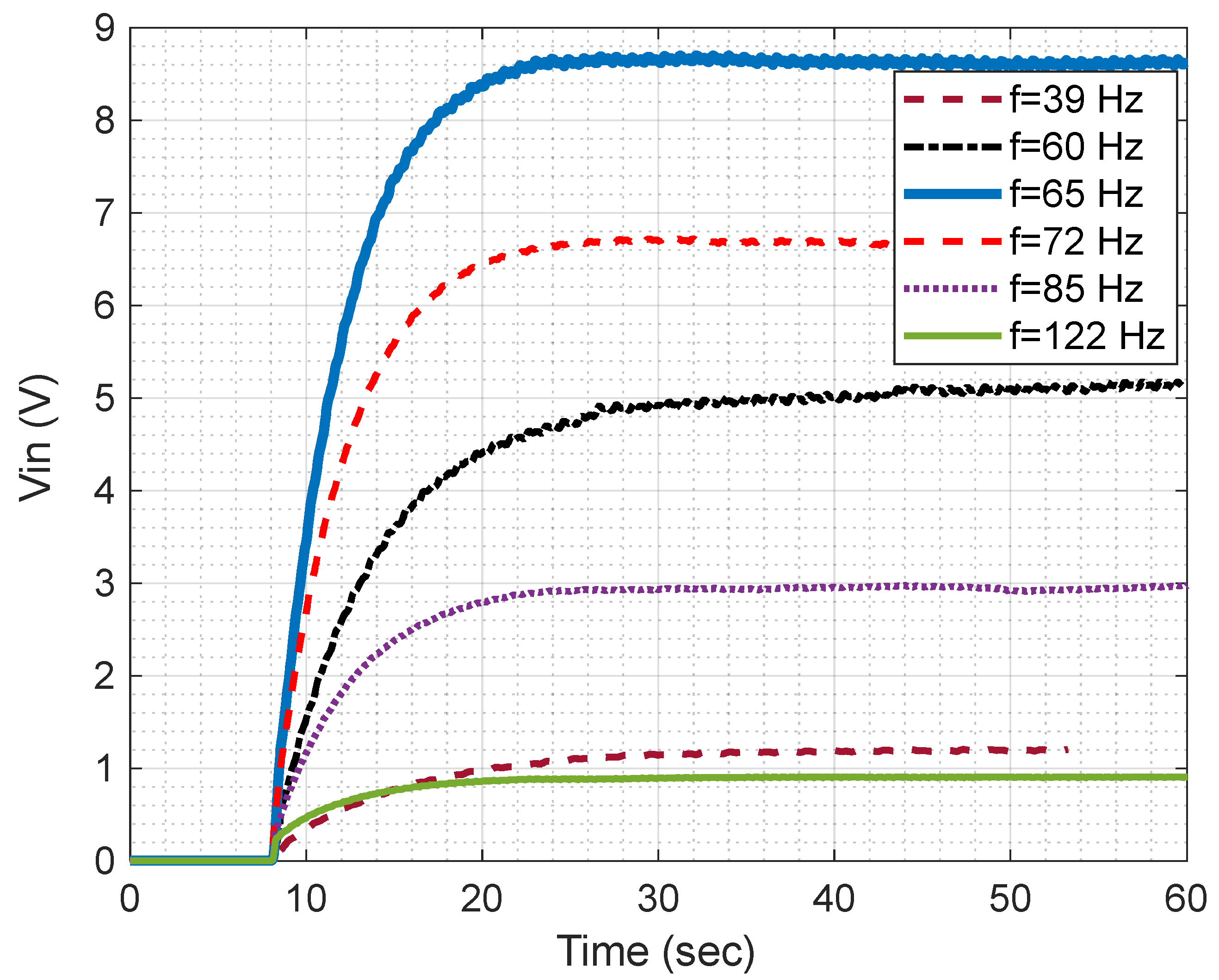
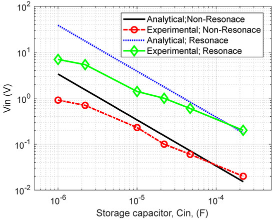
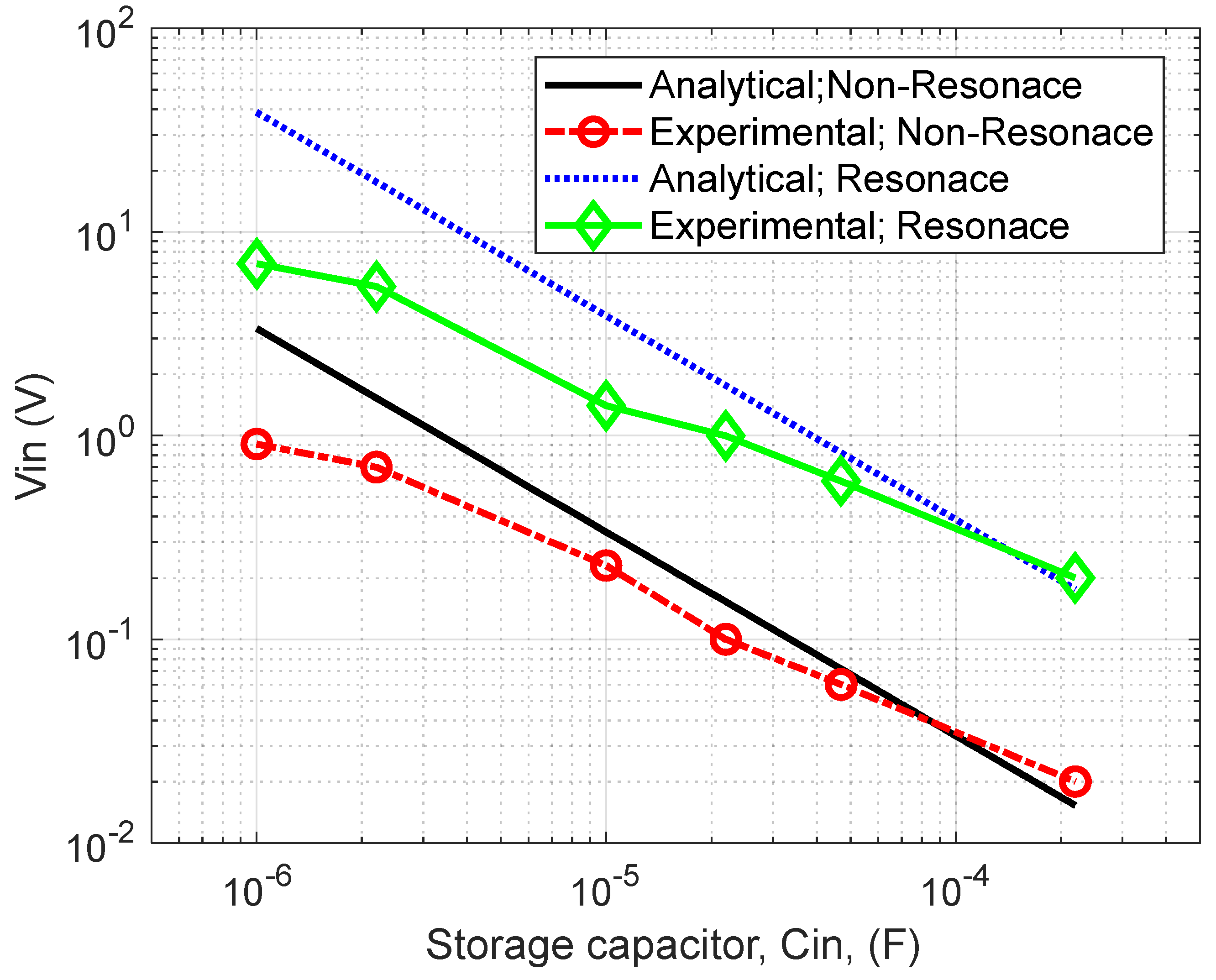
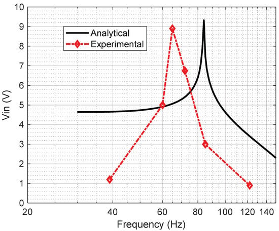
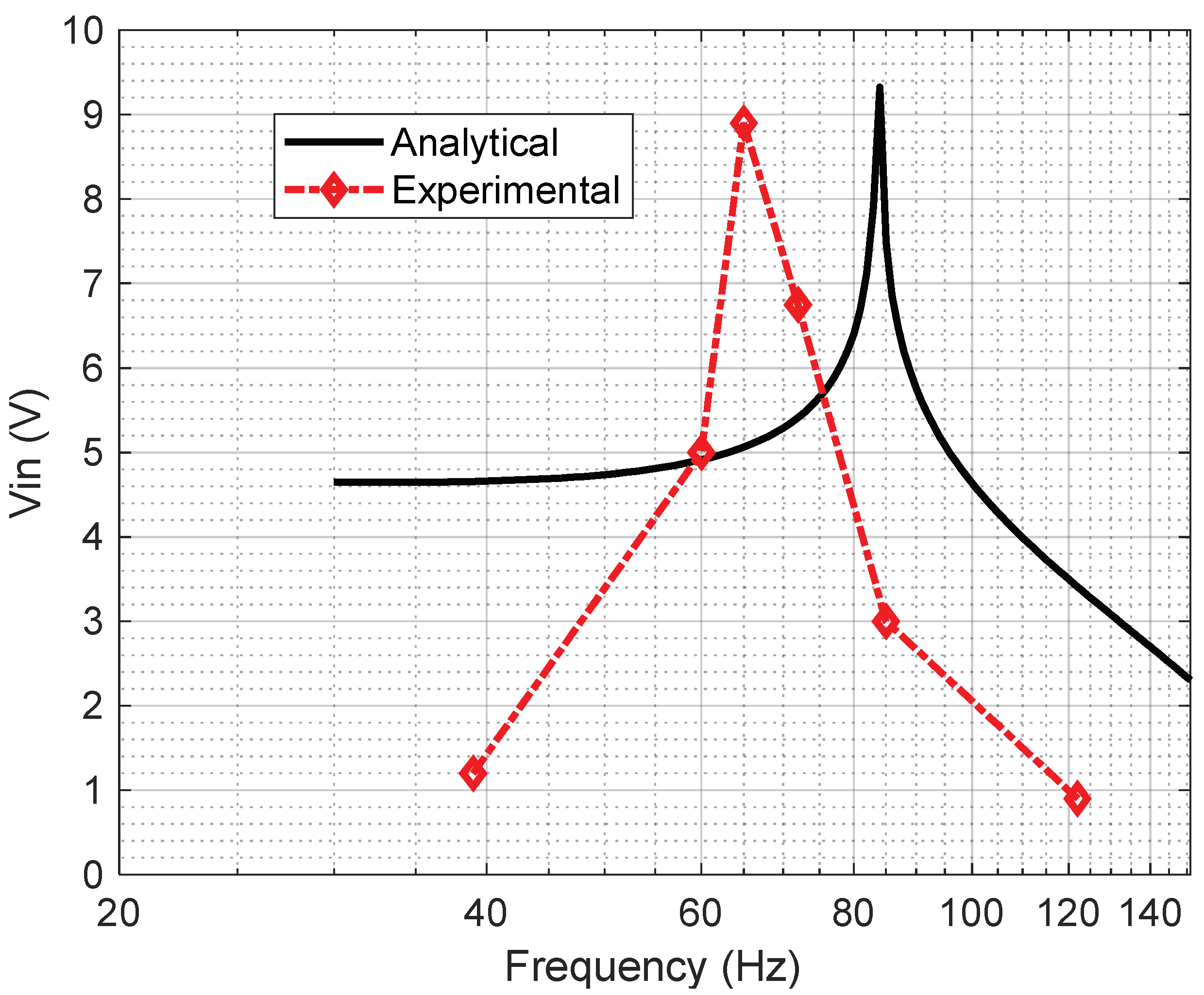
In this section, the performance of the employed CTLPH (specifications in Table 2) is investigated while connected to the Germanium diode bridge. As depicted in Figure 7b, by changing the storage capacitors (Cin), the voltage across the storage capacitors (Vin) was measured. Figure 11 shows that at a frequency of 39 Hz, the voltage of storage capacitor increases and reaches its saturated value of 1.2 V. The effect of frequency is investigated in Figure 12. In non-resonance frequency regions (f < 60 Hz or f > 70 Hz), the generated voltage is less than the generated voltage in resonance frequencies f ≃ 65 Hz. Figure 13 confirms that the stored voltage decreases as the storage capacitance increases, consistent with Equation (39). In addition, the stored voltage across the harvester electrodes was obtained using both analytical calculations and experimental measurements. For certain values of the storage capacitor, the discrepancy between these two methods (i.e., under both resonant and non-resonant conditions) was found to be nearly negligible. Figure 14 also shows that the overall voltage–frequency trend from the experimental results closely matches the analytical prediction. Furthermore, Figure 14 indicates that the resonance frequency can be predicted with an error of approximately 29.7%. This discrepancy between the estimated and experimental resonance frequencies is likely due to variations in the clamping conditions in the experimental setup.
Figure 11.
Storage voltage (Vin) vs. time for various storage capacitors (Cin); f = 39 Hz.
Figure 12.
Storage voltage (Vin) vs. time for various excitation frequencies; Cin = 22 μF.
Figure 13.
Comparison of analytical and experimental values of storage voltage (Vin) for various storage capacitors in a non-resonance (f = 39 Hz) and resonance (f = 65 Hz) frequencies.
Figure 14.
Comparison of analytical and experimental values of storage voltage (Vin) for various excitation frequencies; Cin = 22.
4.5. Voltage and Power of LTC3588
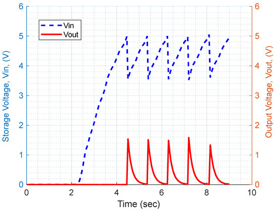
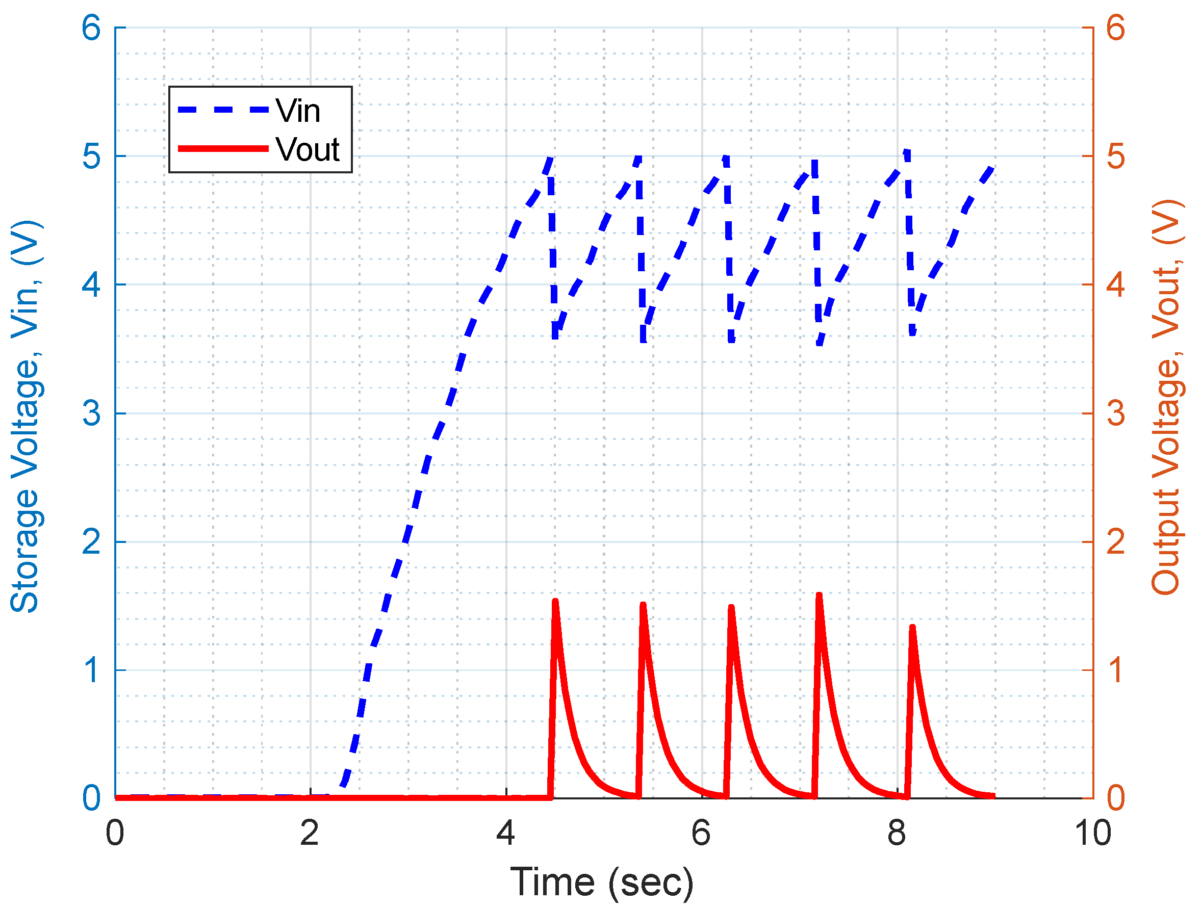
The LTC3588 (Figure 7c) is one of the most common storage modules used in energy harvesting systems, and its modeling was presented in [41]. The performance of the LTC3588 was evaluated when the output terminals of the CTLPH were connected to it, as specified in Table 2. Then, the dependence of the CTLPH on the external resistive load was investigated. As shown in Figure 15, after exciting the CTLPH with a frequency close to resonance frequency (65 Hz), the input storage voltage (Vin) increases across the input capacitor (Cin). No output voltage can be detected for storage voltage less than 5 V (Vin < 5v). After reaching 5 V across the storage capacitor, the internal switch of LTC3588 is energized to transfer a portion of the accumulated charge on the Cin to the output capacitor. Therefore, the voltage across Cin drops to 3.6 V. By charging Cout, the output voltage reaches 1.6 V and discharges through the external resistive load. Since the CTLPH is energizing continuously, the input voltage across the Cin will again reach 5 V and let LTC3588 to connect the input to output to demonstrate a saw shape waveform in the input voltage. Likely the cycle of charging and discharging over the external load can be detected at the output. Note that the Germanium diode bridge introduces a 0.4 V drop, causing a slight delay in charging the storage capacitor at low input voltages. As shown in Figure 15, this effect only shifts the first output spike and does not affect steady-state voltage, as the regulator compensates once the input exceeds the threshold. Based on the energy conservation principle, the stored energy in Cout is equal to the dissipated energy on the external load, , which can be calculated by (46) [39]:
where is the voltage difference between the fully charged condition and the partially discharged condition. Depending on the resistor values in the RC circuit of Figure 7b, the discharge period,, varies [39]. Therefore, the power dissipated on the resistor and its uncertainty can be calculated by (47) and (48), respectively.
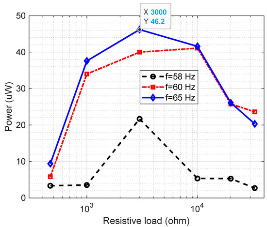
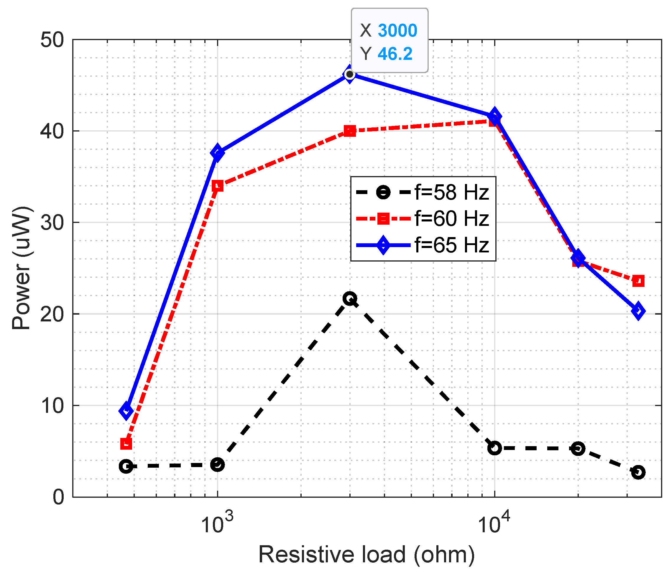
where , , and are the uncertainities of power, output capacitor, output voltage change and discharge period. To investigate the effect of load (i.e., resistance type) on the output power, we measured the voltage drop across the output capacitor Cout for each cycle of charging and discharging. In Figure 16, the output voltage across the external resistive load is shown for different frequencies. When the load is small, the voltage drop across the load is small (e.g., in a short-circuit condition the output voltage is zero). By increasing the external resistive load, the voltage drop across the external load becomes larger. Figure 16 shows that the power will reach its maximum value in one specific resistance and decreases in the higher values. For example, the maximum power for 58, 60 and 65 Hz happens at approximately 3 . It was also confirmed that maximum power can be harvested in the resonance condition. As an example, was measured at 1.33 V for 30 k load at the frequency of 65 Hz. By substituting the measured value of in (47) the discharge energy from the output capacitor (Cout = 47F) is 41.56 . Considering Tdis = 0.9 s, = ±1% of Cout, it causes a power of 46.18 with 0.98 uncertainty. In other words, the maximum output power of the CTLPH running in resonance mode, which is combined with the LTC3588 module, is realized when it is connected to a 3 k external load. Compared with other harvesters presented in Table 3, it seems that the proposed CTLPH operating in resonance condition with 46.18 output power is a good power source for microelectronic sensors or biomedical implants (e.g., 30 W pacemakers). The developed CTLPH prototype, operating at resonance, generated an optimum output power of 46.18 μW at an external resistance of 3 kΩ, which is suitable for powering micropower CO gas sensors [42]. Moreover, cascading 11 such harvesters operating at resonance would be sufficient to supply a wireless sensor with the energy required to transmit collected data to a datalogger (500 μW) for a limited message rate of 10 per day.
Figure 15.
Storage voltage (Vin) and output voltage (Vout) of LTC3588 vs. time, when LTC3588 is connected to the external load Rload = 3 kΩ; Cout = 47 μF; Cin = 22 μF; f = 65 Hz.
Figure 16.
Generated power versus external resistance load, brass substrate; , tp = 0.225 mm; ts = 0.11 mm.
Table 3.
Comparison of the output power of a similar piezoelectric harvester in resonance.
5. Conclusions
This research presents a design guideline for a cantilever triple-layer piezoelectric harvester (CTLPH) with tip mass and tip excitation, operating at resonance. A mathematical model was developed by combining constitutive equations with Euler–Bernoulli beam theory. The model was employed to estimate the effective parameters of the CTLPH, as well as the storage voltage after rectification using a germanium diode bridge. It demonstrated that excitation frequency, piezoelectric coefficients, geometrical dimensions, and the mechanical properties of the layers are all critical factors influencing CTLPH performance. Based on the model, a prototype was fabricated. The model-based predictions regarding the effect of storage capacitance and excitation frequency on storage voltage were confirmed experimentally. Furthermore, the LTC3588 energy storage module was employed to store the generated charge from resonance motion. A non-contact measurement method was employed to determine the bending stiffness of the prototype. The output power after the energy storage module was measured for frequencies near the resonance condition (f = 65 Hz) under various resistive loads. Results confirmed that both excitation frequency and external resistance significantly affect the maximum harvested power. The developed CTLPH prototype, operating at resonance, generated an optimum output power of 46.18 ± 0.98 μW at an external resistance of 3 kΩ, which is suitable for powering micropower sensors.
Author Contributions
Conceptualization, M.G.; methodology, M.G., M.M. and J.G.; software, M.G., J.G., M.M. and P.S.; validation, M.G. and M.M.; formal analysis, M.G., M.M. and P.S.; investigation, M.G.; resources, M.G.; data curation, M.G.; writing—original draft preparation, M.G.; writing—review and editing, M.M., P.S. and J.G.; visualization, M.G. and M.M.; supervision, M.G.; project administration, M.G.; funding acquisition, M.G. All authors have read and agreed to the published version of the manuscript.
Funding
This research was funded by the University of Portsmouth, grant number “New Appointee Funding, 41001”.
Data Availability Statement
All data are available upon request from the corresponding author.
Acknowledgments
This work was performed on the equipment of the University of Portsmouth.
Conflicts of Interest
The authors declare no conflicts of interest.
References
- Statista. IoT Connections Worldwide 2034. Available online: https://www.statista.com/statistics/1183457/iot-connected-devices-worldwide/ (accessed on 31 January 2026).
- Song, H.; Kim, S.; Kim, H.S.; Lee, D.; Kang, C.; Nahm, S. Piezoelectric Energy Harvesting Design Principles for Materials and Structures: Material Figure-of-Merit and Self-Resonance Tuning. Adv. Mater. 2020, 32, e2002208. [Google Scholar] [CrossRef] [Scilit] [PubMed]
- Sadeghian, O.; Mohammadi-Ivatloo, B.; Oshnoei, A.; Aghaei, J. Unveiling the potential of renewable energy and battery utilization in real-world public lighting systems: A review. Renew. Sustain. Energy Rev. 2023, 192, 114241. [Google Scholar] [CrossRef] [Scilit]
- Zhang, Y.; Wang, W.; Wu, X.; Lei, Y.; Cao, J.; Bowen, C.; Bader, S.; Yang, B. A comprehensive review on self-powered smart bearings. Renew. Sustain. Energy Rev. 2023, 183, 113446. [Google Scholar] [CrossRef] [Scilit]
- Ahnood, A.; Ndabakuranye, J.P.; Li, S.; Kavehei, O.; Prawer, S. Miniature power and data transceiver based on multimodal operation of a single photovoltaic device. Eng. Res. Express 2020, 2, 015036. [Google Scholar] [CrossRef] [Scilit]
- Yang, C.; Li, H.; Tang, Y.; Wang, H.; Lu, Y. A hybrid vibration energy harvester with integrated piezoelectric and electrostatic devices. Jpn. J. Appl. Phys. 2023, 62, 064501. [Google Scholar] [CrossRef] [Scilit]
- Budlayan, M.L.M.; Patricio, J.N.; Arco, S.D.; A Guerrero, R. Electrowetting-on-dielectric behavior of aqueous droplets and gold nanofluid on an electrospun poly(vinyl chloride) microfiber layer. Mater. Res. Express 2024, 11, 035303. [Google Scholar] [CrossRef] [Scilit]
- Zheng, X.; Han, L.; Yang, J.; Li, Q.; He, L. Piezoelectric breeze energy harvester with mechanical intelligence mechanism for smart agricultural monitoring systems. Smart Mater. Struct. 2024, 33, 065027. [Google Scholar] [CrossRef] [Scilit]
- Ghodsi, M.; Ziaiefar, H.; Mohammadzaheri, M.; Al-Yahmedi, A. Modeling and characterization of permendur cantilever beam for energy harvesting. Energy 2019, 176, 561–569. [Google Scholar] [CrossRef] [Scilit]
- Prince, K.J.; Mirletz, H.M.; Gaulding, E.A.; Wheeler, L.M.; Kerner, R.A.; Zheng, X.; Schelhas, L.T.; Tracy, P.; Wolden, C.A.; Berry, J.J.; et al. Sustainability pathways for perovskite photovoltaics. Nat. Mater. 2024, 24, 22–33. [Google Scholar] [CrossRef] [Scilit] [PubMed]
- Kapsalis, V.; Maduta, C.; Skandalos, N.; Wang, M.; Bhuvad, S.S.; D’AGostino, D.; Ma, T.; Raj, U.; Parker, D.; Peng, J.; et al. Critical assessment of large-scale rooftop photovoltaics deployment in the global urban environment. Renew. Sustain. Energy Rev. 2023, 189, 114005. [Google Scholar] [CrossRef] [Scilit]
- Teng, J.; Cao, Z.; Ren, C.; Xu, J.; Guo, X.; Ye, X. Efficient energy harvesting from broadband low-frequency vibrations via 3D-interdigital electrostatic generator. Appl. Energy 2025, 388, 125701. [Google Scholar] [CrossRef] [Scilit]
- Asadi, M.; Ahmadi, R.; Abazari, A.M. Halbach magnet arrays in electromagnetic kinetic energy harvesters: A review. Energy Convers. Manag. X 2024, 22, 100544. [Google Scholar] [CrossRef] [Scilit]
- Zhang, T.; Wang, L.; Liu, L.; Li, W.; Wu, S.; Guo, J.; Zhou, G. Optimizing Bipolar Reset Waveform to Improve Grayscale Stability in Active Matrix Electrowetting Displays. Micromachines 2024, 15, 1247. [Google Scholar] [CrossRef] [Scilit] [PubMed]
- Long, S.X.; Khoo, S.Y.; Ong, Z.C.; Soong, M.F.; Huang, Y.-H.; Prasath, N.; Noroozi, S. A comprehensive review on mechanical amplifier structures in piezoelectric energy harvesters. Mech. Adv. Mater. Struct. 2023, 31, 7244–7273. [Google Scholar] [CrossRef] [Scilit]
- El-Bahrawy, F.T.; Hussein, R.K.; El-Sayed, A.T.; Wafaie, M. Piezoelectric Harvester Proportional–Derivative (PHPD) Control for Nonlinear Dynamics Reduction in Underactuated Hybrid Systems. Machines 2025, 13, 830. [Google Scholar] [CrossRef] [Scilit]
- Yang, S.; Chen, H.; Zhang, Z.; Wang, W.; Niu, X.; Lu, X. A bioinspired piezoelectric stick-slip actuator designed by the moving posture of monkey. Rev. Sci. Instrum. 2025, 96, 095003. [Google Scholar] [CrossRef] [Scilit]
- Franco, I.P.; Morales-Masis, M.; Mora-Seró, I.; Vidal, R. Comparative life cycle assessment of lead-free halide perovskite composites/polymer for piezoelectric energy harvesting. Sustain. Energy Fuels 2025, 9, 4375–4391. [Google Scholar] [CrossRef] [Scilit]
- Yang, P.; Mazlan, A.Z.A. Experimental study on long-term fatigue behavior of piezoelectric energy harvesters under high and low-frequency vibration excitation. Int. J. Fatigue 2025, 194, 108817. [Google Scholar] [CrossRef] [Scilit]
- Salazar, R.; Larkin, K.; Abdelkefi, A. Piezoelectric property degradation and cracking impacts on the lifetime performance of energy harvesters. Mech. Syst. Signal Process. 2021, 156, 107697. [Google Scholar] [CrossRef] [Scilit]
- Fang, S.; Chen, K.; Lai, Z.; Zhou, S.; Liao, W.-H. Analysis and experiment of auxetic centrifugal softening impact energy harvesting from ultra-low-frequency rotational excitations. Appl. Energy 2022, 331, 120355. [Google Scholar] [CrossRef] [Scilit]
- Shi, G.; Tong, D.; Xia, Y.; Jia, S.; Chang, J.; Li, Q.; Wang, X.; Xia, H.; Ye, Y. A piezoelectric vibration energy harvester for multi-directional and ultra-low frequency waves with magnetic coupling driven by rotating balls. Appl. Energy 2022, 310, 118511. [Google Scholar] [CrossRef] [Scilit]
- Dong, L.; Closson, A.B.; Oglesby, M.; Escobedo, D.; Han, X.; Nie, Y.; Huang, S.; Feldman, M.D.; Chen, Z.; Zhang, J.X. In vivo cardiac power generation enabled by an integrated helical piezoelectric pacemaker lead. Nano Energy 2019, 66, 104085. [Google Scholar] [CrossRef] [Scilit]
- Khazaee, M.; Hasani, M.; Riahi, S.; Rosendahl, L.; Rezania, A. Harnessing cardiac power: Heart kinetic motion analysis for energy harvesters. Biomed. Signal Process. Control 2024, 95, 106421. [Google Scholar] [CrossRef] [Scilit]
- Wu, Y.; Qiu, J.; Zhou, S.; Ji, H.; Chen, Y.; Li, S. A piezoelectric spring pendulum oscillator used for multi-directional and ultra-low frequency vibration energy harvesting. Appl. Energy 2018, 231, 600–614. [Google Scholar] [CrossRef] [Scilit]
- Smits, J.G.; Dalke, S.I.; Cooney, T.K. The constituent equations of piezoelectric bimorphs. Sens. Actuators A Phys. 1991, 28, 41–61. [Google Scholar] [CrossRef] [Scilit]
- DeVoe, D.; Pisano, A. Modeling and optimal design of piezoelectric cantilever microactuators. J. Microelectromechanical Syst. 1997, 6, 266–270. [Google Scholar] [CrossRef] [Scilit]
- Weinberg, M. Working equations for piezoelectric actuators and sensors. J. Microelectromechanical Syst. 1999, 8, 529–533. [Google Scholar] [CrossRef] [Scilit]
- Wang, Q.-M.; Cross, L. Constitutive equations of symmetrical triple layer piezoelectric benders. IEEE Trans. Ultrason. Ferroelectr. Freq. Control 1999, 46, 1343–1351. [Google Scholar] [CrossRef] [Scilit]
- Tadmor, E.; Kosa, G. Electromechanical coupling correction for piezoelectric layered beams. J. Microelectromechanical Syst. 2003, 12, 899–906. [Google Scholar] [CrossRef] [Scilit]
- Lu, Q.; Liu, L.; Scarpa, F.; Leng, J.; Liu, Y. A novel composite multi-layer piezoelectric energy harvester. Compos. Struct. 2018, 201, 121–130. [Google Scholar] [CrossRef] [Scilit]
- Cao, Y.; Wang, J.; Liao, Y.; Tang, L. A comprehensive dynamic continuous model of piezoelectric stack energy harvesters under arbitrary excitation considering electrodes and protective layers. J. Phys. D Appl. Phys. 2023, 56, 464001. [Google Scholar] [CrossRef] [Scilit]
- Luo, A.; Tan, Q.; Xu, W.; Huang, J.; Gu, S.; Guo, X.; Lee, C.; Fan, K.; Wang, F. A Comprehensive Review of Energy Harvesting From Kinetic Energy at Low Frequency. Adv. Mater. Technol. 2025, 10, 2401731. [Google Scholar] [CrossRef] [Scilit]
- Sun, Q.; Tian, J.; Qin, Z.; Li, H.; Shen, J.; Zhang, P.; Chen, W.; Zhou, J. Superhydrophobic Piezoelectric Device for Efficient Raindrop Energy Harvesting. ACS Appl. Energy Mater. 2025, 8, 7322–7329. [Google Scholar] [CrossRef] [Scilit]
- Rezaei, M.; E Khadem, S.; Firoozy, P. Broadband and tunable PZT energy harvesting utilizing local nonlinearity and tip mass effects. Int. J. Eng. Sci. 2017, 118, 1–15. [Google Scholar] [CrossRef] [Scilit]
- Upendra, B.; Panigrahi, B.; Gr, S. Effect of geometric non-linearity and tip mass on the frequency bandwidth of a cantilever piezoelectric energy harvester under tip excitation. Phys. Scr. 2023, 98, 065203. [Google Scholar] [CrossRef] [Scilit]
- Xia, G.; Fang, F.; Wang, Q.; Zhang, M.; Wang, J. Performance analysis of piezoelectric energy harvesters with a tip mass and nonlinearities of geometry and damping under parametric and external excitations. Arch. Appl. Mech. 2020, 90, 2297–2318. [Google Scholar] [CrossRef] [Scilit]
- Tang, L.; Wang, J. Size effect of tip mass on performance of cantilevered piezoelectric energy harvester with a dynamic magnifier. Acta Mech. 2017, 228, 3997–4015. [Google Scholar] [CrossRef] [Scilit]
- Ghodsi, M.; Mohammadzaheri, M.; Soltani, P. Analysis of Cantilever Triple-Layer Piezoelectric Harvester (CTLPH): Non-Resonance Applications. Energies 2023, 16, 3129. [Google Scholar] [CrossRef] [Scilit]
- Inman, D.J.; Singh, R.C. Engineering Vibration; Pearson: London, UK, 2014. [Google Scholar]
- Ghodsi, M.; Mohammadzaheri, M.; Soltani, P. Modeling of the energy storage device: LTC3588. Int. J. Chem. Mol. Eng. 2025, 19, 9–13. [Google Scholar]
- Kim, J.-H.; Mirzaei, A.; Kim, H.W.; Kim, S.S. Low power-consumption CO gas sensors based on Au-functionalized SnO2-ZnO core-shell nanowires. Sens. Actuators B Chem. 2018, 267, 597–607. [Google Scholar] [CrossRef] [Scilit]
- Liu, H.; Tay, C.J.; Quan, C.; Kobayashi, T.; Lee, C. Piezoelectric MEMS Energy Harvester for Low-Frequency Vibrations With Wideband Operation Range and Steadily Increased Output Power. J. Microelectromechanical Syst. 2011, 20, 1131–1142. [Google Scholar] [CrossRef] [Scilit]
- Quintero, A.V.; Besse, N.; Janphuang, P.; Lockhart, R.; Briand, D.; de Rooij, N.F. Design optimization of vibration energy harvesters fabricated by lamination of thinned bulk-PZT on polymeric substrates. Smart Mater. Struct. 2014, 23, 045041. [Google Scholar] [CrossRef] [Scilit]
- Durou, H.; Rodriguez, G.A.A.; Ramond, A.; Dollat, X.; Rossi, C.; Esteve, D. Micromachined Bulk PZT Piezoelectric Vibration Harvester to Improve Effectiveness Over Low Amplitude and Low Frequency Vibrations. In Proceedings of the Power MEMS’10, Leuven, Belgium, 30 November–3 December 2010; pp. 27–30. [Google Scholar]
- Huang, M.; Hou, C.; Li, Y.; Liu, H.; Wang, F.; Chen, T.; Yang, Z.; Tang, G.; Sun, L. A Low-Frequency MEMS Piezoelectric Energy Harvesting System Based on Frequency Up-Conversion Mechanism. Micromachines 2019, 10, 639. [Google Scholar] [CrossRef] [Scilit]
- Debnath, B.; Kumar, R. A Comparative Simulation Study of the Different Variations of PZT Piezoelectric Material by Using A MEMS Vibration Energy Harvester. IEEE Trans. Ind. Appl. 2022, 58, 3901–3908. [Google Scholar] [CrossRef] [Scilit]

Disclaimer/Publisher’s Note: The statements, opinions and data contained in all publications are solely those of the individual author(s) and contributor(s) and not of MDPI and/or the editor(s). MDPI and/or the editor(s) disclaim responsibility for any injury to people or property resulting from any ideas, methods, instructions or products referred to in the content. |
© 2026 by the authors. Licensee MDPI, Basel, Switzerland. This article is an open access article distributed under the terms and conditions of the Creative Commons Attribution (CC BY) license.