Perspective

Energy-Efficient Towing of Floating Offshore Wind Turbines: Challenges and Perspectives on Platform Drag Reduction


1
Department of Mechanical Engineering, University of Malta, MSD 2080 Msida, Malta
2
School of Mechanical Engineering, Beijing Institute of Technology, Beijing 100811, China
3
State Key Laboratory of Hydraulic Engineering Intelligent Construction and Operation, Tianjin University, Tianjin 300072, China
4
National Key Laboratory Hydrodynamics, Chin Ship Scientific Research Centre, Wuxi 214082, China
*
Authors to whom correspondence should be addressed.
Energies 2026, 19(3), 797; https://doi.org/10.3390/en19030797
Submission received: 30 December 2025 / Revised: 22 January 2026 / Accepted: 30 January 2026 / Published: 3 February 2026
(This article belongs to the Section A3: Wind, Wave and Tidal Energy)

Abstract

Floating offshore wind turbines (FOWTs) are essential for expanding renewable energy capacity into deep-water regions. However, the deployment of semi-submersible FOWTs faces significant operational and financial hurdles, primarily driven by the high costs and logistical complexity of towing these structures to site. This perspective paper critiques current transportation processes, noting that existing offshore guidelines typically fail to account for the hydrodynamic drag generated by the unique bluff-body geometries of these hulls. The substantial pressure drag inherent in these structures leads to excessive fuel consumption and elevated carbon emissions during long-distance transit. Consequently, potential drag-reduction strategies must be explored to address these hydrodynamic inefficiencies. Among various technologies, fairings attached to the FOWT structure emerge as a promising solution, with potential drag reductions of around 40%. However, extensive research is required to ensure these designs do not compromise system stability, while also providing a net carbon emission reduction that justifies their production for large-scale deployment. Ultimately, integrating effective drag-reduction technologies is a vital step towards improving both the economic viability and the environmental footprint of the FOWT industry, ensuring its long-term sustainability in the global energy transition.

1. Introduction

The increased global push for renewable energy generation has led to a boost in offshore energy sources, maximising the potential of global natural resources. By 2024, a total of 1136 GW of wind power was generated globally, of which 83.2 GW was generated by offshore wind farms, equivalent to around 7.3% of offshore energy [1]. Fixed-bottom projects accounted for around 99.7% of the offshore energy capacity, while floating projects only represented a small percentage due to being in the early stages of commercialisation [2]. With ever increasing energy demands and advances in technologies, the 2025 Global Offshore Wind Report published by the Global Wind Energy Council (GWEC) forecasts that by 2034 floating wind energy generation capacity will reach around 19 GW [2]. Meanwhile, the growth of fixed-bottom structures is progressively being constrained due to the scarcity of shallow waters suitable for such structures. The deployment of floating foundations will therefore allow to further extend offshore wind capacity into deeper waters, expanding the use of wind energy to more nations worldwide.
Floating Offshore Wind Turbines (FOWTs) offer several benefits that make them a practical alternative where fixed-bottom structures are not feasible. These traditional bottom-fixed turbines are limited to water depths of approximately 50 to 60 m, restricting their application to around 20% of offshore wind potential globally [3]. By contrast, floating technologies could unlock the majority of remaining potential, including around 80% of offshore zones in Europe and Japan, as well as around 60% of those in the United States [4]. As offshore structures are deployed in deeper waters, they are exposed to harsher weather conditions, including strong currents, high waves, and corrosive marine environments. These factors can present additional challenges in the design, installation, and operation of such structures. Nevertheless, current floating technologies have already proven capable in such operating conditions, benefiting from the knowledge transferred from the oil and gas (O&G) industry, which has extensive experience in deploying large floating structures in deep offshore sites [5]. Additionally, FOWTs also reduce visual and noise impacts, typically associated with onshore or close to shore wind turbines, due to their distance from coastlines. Furthermore, since floating structures do not require the use of seabed foundations, seabed disturbance and the associated ecological impacts are greatly reduced, or even eliminated. However, given that the FOWT sector is still in an early stage of development and commercialisation, research on their long-term environmental impacts is still limited. It is therefore essential that comprehensive research and data collection are carried out to confirm the anticipated reductions in environmental impact.
Although FOWTs have many benefits, they also face several limitations that create technical, operational, and financial challenges. The main barrier for FOWT development is the significant capital investment required. With the FOWT technology still in a pre-commercial stage, each project demands hundreds of millions of euros for operational lifetimes that can extend beyond 20 years. The shift toward larger turbines, reaching 15 to 20 MW per turbine, also necessitates significantly large financial support. These increase the demand for port and manufacturing infrastructure, both during manufacturing and for maintenance, which many countries currently lack. In such cases, the FOWTs would have to be assembled in neighbouring countries and individually towed to the required sites, requiring complex logistical planning which further increases the high operational costs during their deployment. Furthermore, the transportation and installation of such large structures are highly dependent on specific weather conditions due to difficulties in marine operations that are faced during significant wave heights and high wind speeds. Ideal weather windows are typically quite narrow; therefore, careful scheduling and organisation are essential for safe operations [6]. The efficiency and cost of FOWT towing are heavily influenced by the hydrodynamic drag experienced by the platform. Consequently, the development and implementation of effective drag-reduction technologies are paramount to improving the economic feasibility of FOWT projects. The importance of these technologies is further underscored by the need to tow platforms back to port for periodic major maintenance. Once the FOWTs are installed and in operation, their maintenance introduces further complications. It is expected that in the 25-year operational lifetime of FOWTs, they are towed back to port at least three times for major maintenance, making optimisation of transportation processes essential for more efficient and sustainable towing.

1.1. Current FOWT Technologies

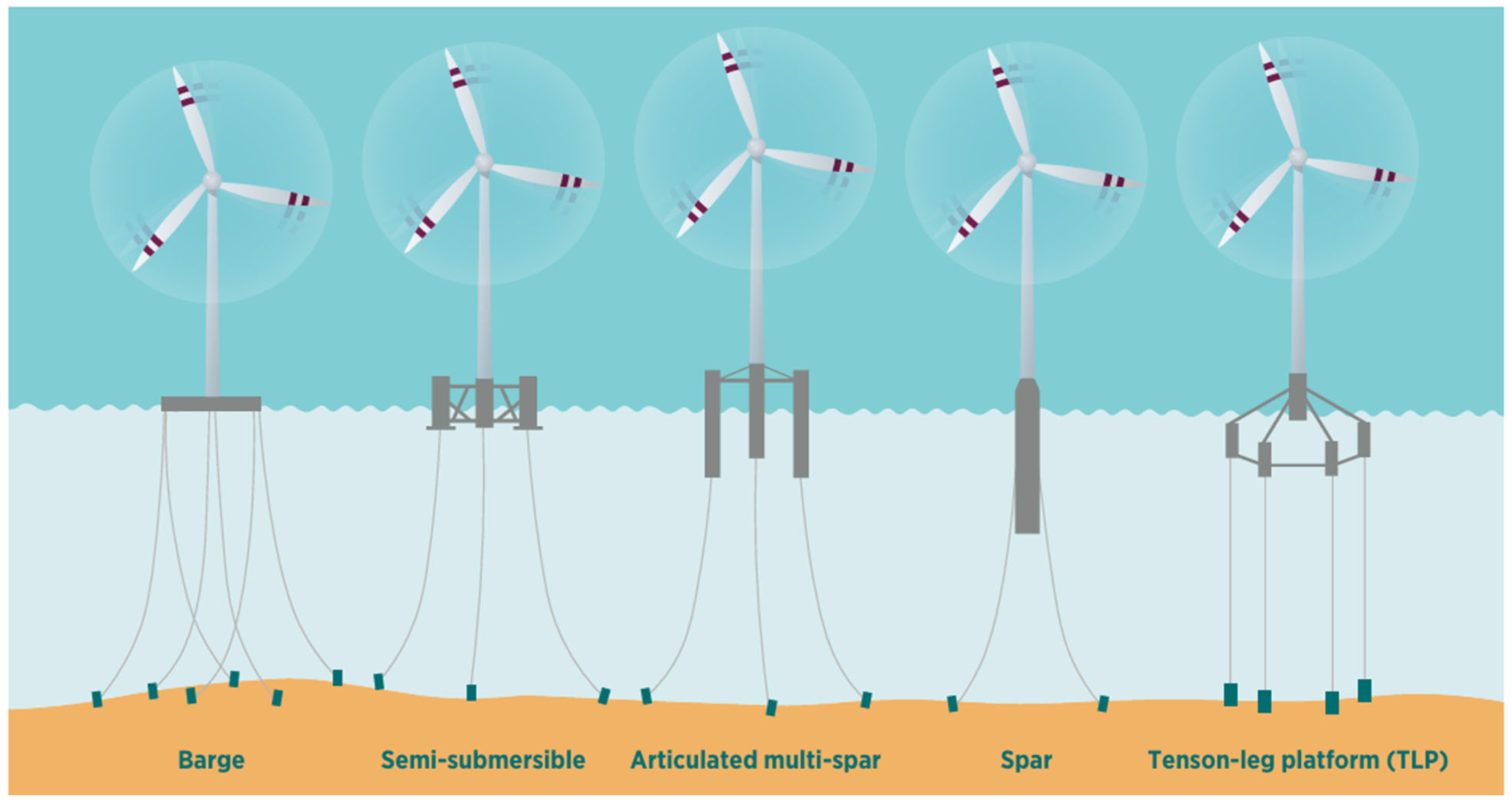
FOWTs employ several different types of floating platforms, typically distinguished by the stability mechanism employed. These are sub-divided as buoyancy-stabilised, ballast-stabilised, and mooring-stabilised [4]. The choice of platform is dependent on a range of factors, including site-specific conditions and technological characteristics, as well as logistical and economic requirements. Figure 1 depicts the most common types of platforms available. The transportation and installation of FOWTs are critical phases of any offshore project, presenting significant costs and logistical hurdles. These processes vary considerably depending on the specific type of floating structure and the characteristics of the installation site. The deployment of a floating platform involves either onshore or offshore assembly. In the former, the platform is built in a port and towed to site, while the latter requires transporting the separate components offshore for final construction using specialized vessels. Different vessels are available for different transportation procedure, with the main vessel types used being tugboats, crane barges, heavy lift vessels, and purpose-built jack-up or construction vessels [7].
Buoyancy-stabilised platforms, or waterplane-stabilised platforms, rely on a substantial waterplane area to achieve the righting moment necessary for stability. This geometry provides the high second moment of area required to counteract rotational displacements and return the system to equilibrium. Semi-submersible platforms are the most common type of buoyancy-stabilised structures, being suitable for a wide range of depths. These are typically composed of several large columns, typically employing three or four columns, connected using bracing or submerged pontoons [4]. Semi-submersible structures can be manufactured and assembled onshore or in a dry dock and transported to the required site by towing the whole structure. To allow for easier transportation, a ballast system varies the platform’s draught, which is typically reduced to below 10 m to lower the drag experienced while being towed [6]. Tugboat-assisted towing procedures often require multiple days to complete due to low speed, typically in the range of 2 to 4 knots, and can take even longer due to the need for specific weather conditions [8].
Ballast-stabilised platforms depend on the distance between the total system’s centre of gravity and the centre of buoyancy. By including large ballasts at the bottom of the structure, the centre of gravity is moved further below the centre of buoyancy, hence increasing the stabilising righting moment required to offset rotational displacements generated as the floating platform tilts due to environmental conditions to return the structure to its equilibrium position. The most common ballast-stabilised platforms are spar floaters, which are composed of a long cylindrical structure with a heavy ballast at its base to lower its centre of gravity [4]. Spar-type platforms can have structures that extend to around 85 m below the water surface for a 10 MW wind turbine, limiting their use to water depths of beyond 100 m [9]. Their transportation and installation can be quite complex due to their large draught, requiring offshore assembly with increased logistical demands. The ballast is towed to site using tugboats and water-ballasted to upend the structure. The water ballast is then replaced by a fixed ballast to keep the structure upright, and the wind turbine is installed to the ballasted platform using a heavy-lift vessel.
In contrast to ballast- and buoyancy-stabilised platforms, mooring-stabilised platforms rely on their mooring systems, which are highly tensioned, to provide the required righting moment to bring the platform back to equilibrium. The mooring system is composed of different mooring lines, called tendons, which are secured to the seabed to provide the required tension. Tension leg platforms (TLP) are the main type of mooring-stabilised platforms, typically comprised of a central column with arms that are connected to the tensioned tendons [4]. TLPs are mostly suitable for intermediate water depths, typically between 70 and 200 m [6]. The taut mooring lines create a fixed draught for the platform, making it behave like a constrained structure in the vertical direction while resembling a floating structure horizontally. Due to their small and light structure in comparison to other platforms, TLP can be assembled onshore and then transported to site. However, since TLPs depend on the mooring system for stability, the structure is inherently unstable during towing. Temporary buoyancy modules or a bespoke barge platform can be used for towing the TLP, with the added modules being ballasted once the platform has reached the required installation site.
Figure 1. Different types of floating platforms [10]. Barge and semi-submersible are buoyancy-stabilised; articulated multi-spar and spar are ballast-stabilised; and tension-leg platform is mooring-stabilised.
Energies 19 00797 g001

1.2. Aim

Semi-submersible platforms are considered to be the most mature FOWT technology, having most knowledge adopted from the O&G industry and a Technology Readiness Level (TRL) of around 8 to 9. Multiple projects and demonstrators are already operating around the world. However, multiple challenges are faced when transporting these semi-submersible platforms by towing. These often result in an increase in costs and carbon emissions, mainly as a result of the platform drag. In the near future, floating offshore wind farms are expected to expand worldwide, with numerous large-scale projects planned to be operating by 2050, each containing dozens of turbines.
This paper will present the current transportation process employed for semi-submersible FOWT platforms and the main challenges faced due to the drag present. In this context, the aim of this paper is to present different methods that can be potentially used during the transportation process of semi-submersible platforms to reduce the platform drag, hence reducing costs and towing requirements and increasing the overall energy efficiency of the towing process. It also aims to highlight different knowledge gaps in research about towing of semi-submersible FOWTs and drag-reduction systems for such platforms.

2. Transportation of FOWT

The transportation and installation processes are highly dependent on the type of floating structures being employed, as well as the final installation site of the structure. Different vessels are available for different transportation and installation procedures. The use and selection of these vessels are mainly driven by structure type and installation requirements, constrained by both market availability and the project’s budget. The main vessel types available are tugboats, crane barge, heavy lift vessel, jack-up barge, purpose-built jack-up, or construction vessels [7].
Different FOWTs require different installation procedures. These can either be assembled offshore or onshore and then towed to site. Regardless of the assembly process, the anchors and moorings are first installed at the required site. A remotely operated vehicle (ROV) is later on used to retrieve the mooring end and hook it to the floating structure.
For offshore installation operations, a combination of tugboats, barges, and heavy lift vessels are used to transport the different turbine components to site, either by wet towing or dry towing. A heavy-lifting operation is then required to install the turbine onto the floating platform at the installation site. With increasing turbine sizes, available vessels are becoming inadequate in size, and hence more specialised vessels are being required. This increases the logistical demands and operational costs of installation processes due to the limited number of purpose-built vessels worldwide [7]. Offshore assembly is the only viable option for spar-type structures due to their very large draughts.
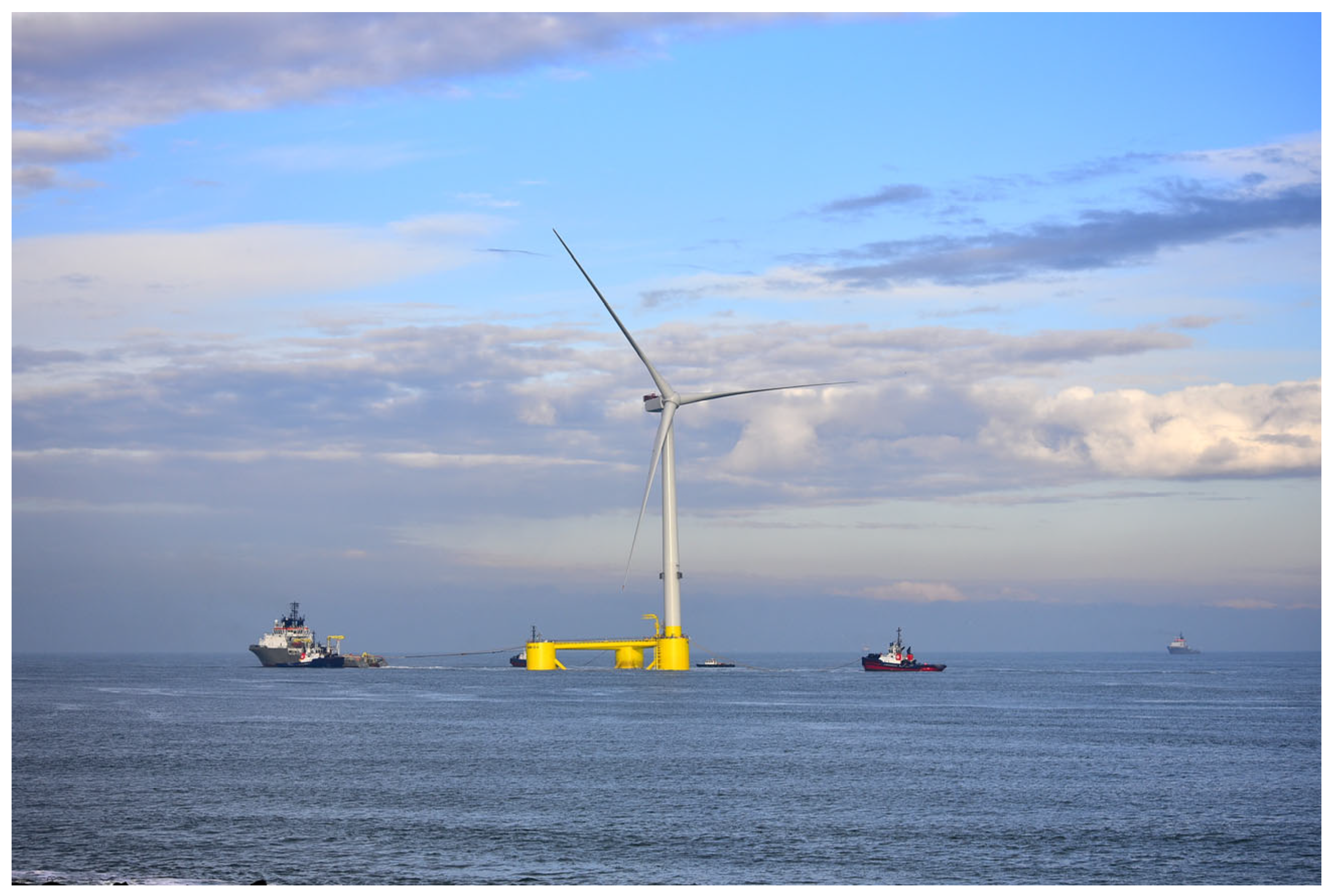
The installation of FOWTs is made significantly simpler through onshore assembly, where the structure is towed to the required location already fully assembled. Onshore assembly permits the use of economical and widely available tugboats for the tow-to-site procedure. Semi-submersibles are most commonly assembled onshore and towed to site, as shown in Figure 2 [11].
The transportation operations of FOWT draw significant inspiration and knowledge transfer from the O&G industry. Most of the transportation and installation procedures, including the choice of vessels used, have been directly adopted to what has been done in previous O&G operations. Vessels such as anchor handling tug supply and procedures such as pre-installation of mooring lines were originally developed for the use of O&G and have been directly transferred to the FOWT industry. The optimization of most O&G operations is a result of years of field experience, where complex marine procedures have been refined by the skills of personnel rather than through dedicated research and analysis.
Current FOWT transportation operations are governed by general offshore standards, including the IMO Guidelines for safe ocean towing, DNV-ST-N001, ISO 29400, and IEC 61400-3-2 [10,13,14,15,16]. While these provide a foundational framework, these standards are not specialised enough for platforms like semi-submersibles where the tow-to-site phase is critical. To advance the industry towards more cost-effective and sustainable transportation methods, further research is essential, especially concerning the critical towing phase of floating platforms like the semi-submersible platforms.

2.1. Towing of Semi-Submersibles

Each FOWT project demands a different transportation procedure, highly dictated by the platform type and location. The semi-submersible platform is often considered the most feasible to transport, as its design allows for complete onshore assembly followed by a tow to-site installation. The platform can be either wet towed in water by tugboats or dry towed on a barge or heavy-lift vessel. However, there is significant cost difference between conventional tugboats, with costs starting from €10,000 per day for each tugboat, and heavy lift vessels, with costs starting from €50,000 per day and can reach up to €250,000 per day depending on vessel size. This makes wet towing the preferred transportation option over dry towing [7,17]. The feasibility of wet towing is reinforced by the semi-submersible platform’s inherent stability, which ensures it remains stable enough for towing by standard tugs, even when ballasted to a shallow draught of around 10 m.
In addition to the initial tow out for installation, towing operations are also required for significant maintenance throughout the semi-submersible’s lifetime. The ‘tow-to-port’ strategy, which involves disconnecting the moorings and towing the FOWT to the nearest port (a distance that can reach beyond 700 km), is currently the most realistic solution for major repairs [17]. This operation is expected to occur at least three times during a FOWT’s lifespan, contributing a significant percentage to the project’s total costs and emissions. It is therefore crucial that the towing operations are optimised and improved to reduce logistical and economical demands and make the FOWT installation process more sustainable.

2.2. Towing Conditions

The towing procedure is dependent on several various factors, including the towing speed, vessel capabilities, weather conditions, and economic consideration. Hence, careful planning and consideration of different parameters need to be done to ensure seamless towing operations.
Semi-submersibles are typically towed at very low speeds, between 2 to 4 knots, equivalent to 1.03 and 2.06 m/s [8]. Due to the large draughts of the floating structures, specific ports with large water depths are required to assemble the semi-submersible FOWT. However, there is a limited number of ports that can accommodate such large structures. This scarcity often forces assembly to take place in a different country from the installation site, resulting in long-distance towing operations that span over 900 km. The combination of extended towing distances and reduced towing speeds results in multi-day operations, which substantially lengthen the total installation timeline. The Kincardine Project is an example of such installations, where FOWTs were towed between Rotterdam in the Netherlands and Aberdeen in Scotland, towing them over 700 km in around 10 days [6,17].
Weather conditions have a great impact on towing operations, especially long tows, which can pass through different weather conditions throughout the towing operations. Towing operations require suitable weather conditions to ensure safe execution. The towing operation is therefore limited to specific weather windows that necessitate metocean data analysis during planning to ensure a suitable weather window without many delays or idle waiting time. Wave heights, current speeds, and wind speeds are the metocean parameters that primarily restrict towing operations. Favourable towing conditions involve waves of less than 1 m, while any height over 1.5 m requires the operation to be halted [6]. It is ideal for current speeds to be as minimal as possible, or even zero, to minimise resistance and towing complexity. During towing, the FOWT is kept in a parked–feathered condition to minimise wind resistance. Towing operations are mainly limited to mean wind speeds of below 14 m/s [18].
Due to the wide variations in FOWT designs, each system must be individually analysed before towing. The DNVGL-ST-0119 standard governs the stability requirements for this transit phase, focusing on the relationship between the centre of gravity (COG) and the centre of buoyancy (COB) [19]. A critical part of this analysis is evaluating the FOWT’s intact stability at its planned towing draught, as the COG location changes with draught. Using a reduced draught for transportation can decrease the structure’s inherent stability, potentially leading to increased motions. According to DNVGL-ST-0019 [19], stability assessments must consider both intact and damaged conditions to ensure the platform maintains sufficient restoring capacity under environmental loads. Key hydrostatic parameters include the metacentric height, righting arm curves, and the angle of vanishing stability, which collectively quantify a floating structure’s ability to resist capsizing. Specific requirements for semi-submersible FOWTs must be satisfied to ensure the floating structure maintains sufficient hydrostatic stability under both operational and severe environmental conditions.

2.3. Towing Equipment and Configurations

The safety and success of the entire towing operation are dependent on the proper selection and configuration of key equipment, mainly the tugboats and towlines. The connection system between the FOWT and tugboats consists of structural tow points and a towline attached via shackles, with the potential inclusion of bridles and fairleads depending on the configuration [20]. Different standards and classification society guidelines are available that can be followed to design and size the towing configuration and equipment. The DNVGL ST-N001—Marine operations and marine warranty standard is most commonly used [13].
The DNVGL ST-N001 standard outlines the entire iterative design process that is required to plan the towing process. Key inputs like platform weight, COG location, draught, towing route, and weather conditions are repeatedly checked against stability and strength criteria to ensure adequate strength, stability, and equipment selection. The standard also defines procedures for tug boat selection, towing equipment, and bollard pull requirements, amongst others [13].
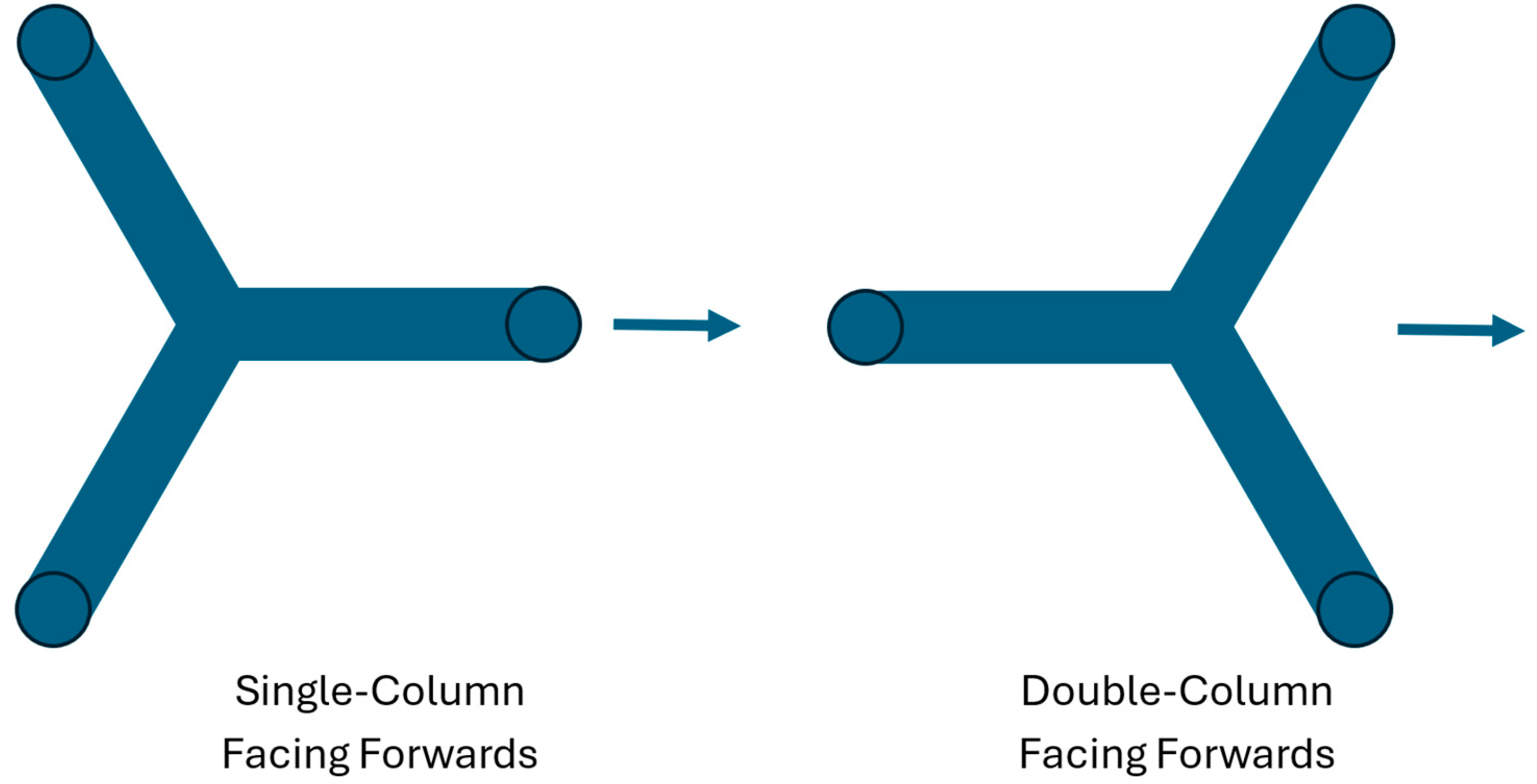
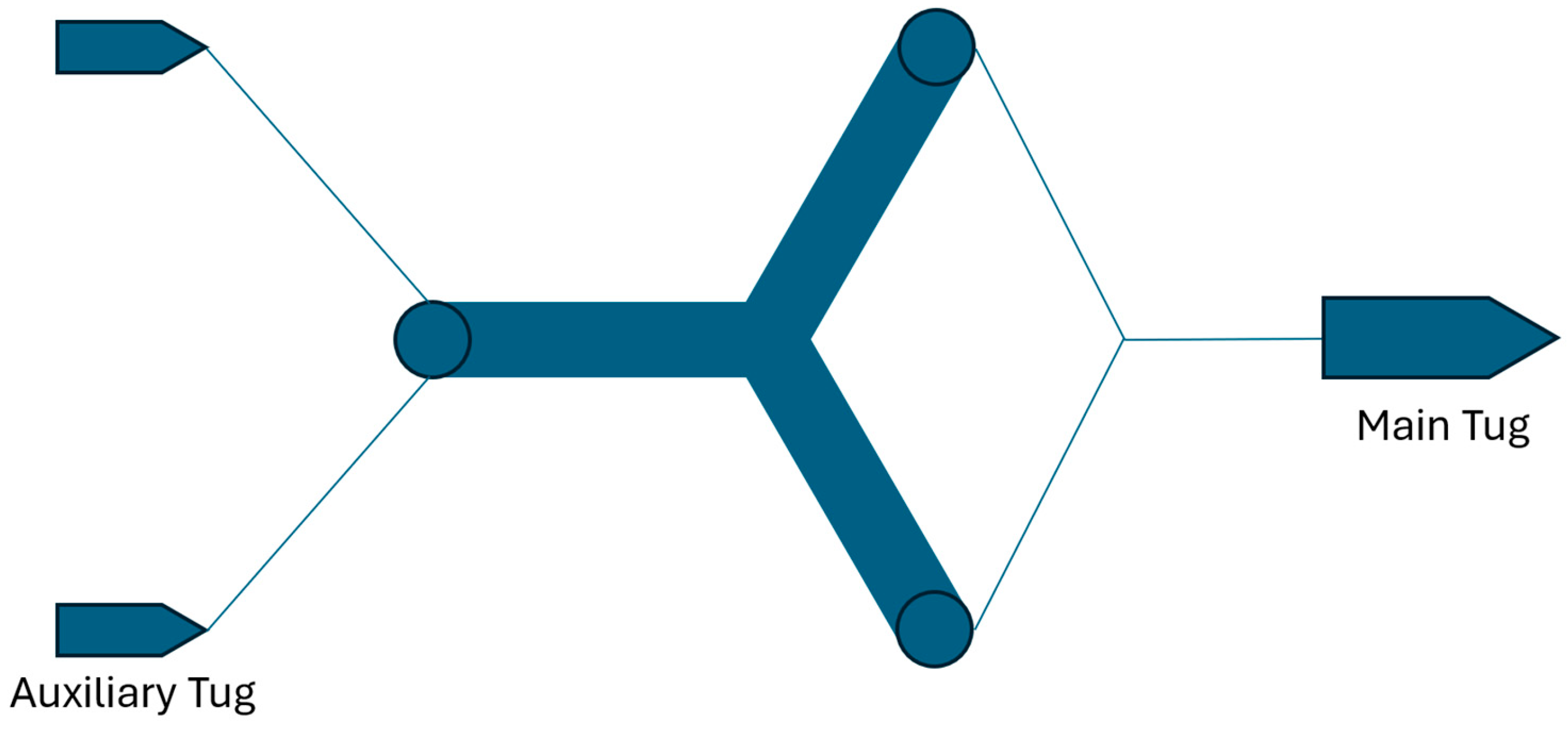
The towing force necessary to move the floating platform is referred to as the bollard pull. The choice of tug boat is mainly based on the minimum bollard pull requirement, typically ranging between 300 and 900 tonnes, subject to the weather conditions and the mass and shape of the platform [8]. The required bollard pull is typically provided by a single large tug boat, while two or three other smaller tug boats help stabilise the motion of the floating platform to ensure that the required course is maintained. The semi-submersible can either be towed with a single-column facing forwards or double-column facing forwards, as shown in Figure 3. Multiple tugs can also be used for the towing operation to provide more steering control and redundancy in case of any failure, such as of towline or tugs, during the towing operation. Figure 4 displays a multiple tug configuration that is typically used for towing operation, highlighting the main and auxiliary tugs.
Towlines are typically connected level to the COG of the system to further ensure a stable system during towing. The main towline is typically made of steel or synthetic fibres, in the form of chains or cables. Other towing connecting components, such as the bridles and shackles, are made of steel to ensure adequate strength [13,21].
The operational performance of the selected tugs is another key parameter to be considered, with their fuel efficiency and emissions output being critical factors in the sustainability and cost of the towing phase. Tugboats burn a large amount of fuel during their operation, with fuel consumption and carbon emission rates highly dependent on the tugboat efficiency and operating conditions. The main carbon emissions of the installation process of these FOWTs stem from the fuel consumed by the towing vessels during the transportation process. For every tonne of fuel consumed, around 3.15 tonnes of CO2 is produced [22]. Tugboats can consume up to around 80 tonnes per day of fuel when running at full speed. The maximum speed of tugboats is typically around 18 knots; however, the engines would still be required to operate at maximum power when towing large loads at low speeds, hence producing similar emissions [23].

3. Challenges

3.1. Wet Towing

Wet towing remains the most practical and widely adopted method for transporting FOWT, primarily due to its substantially lower cost compared with dry towing using heavy-lift vessels. However, wet towing introduces complex challenges due to the solid–fluid interaction, dominated by hydrodynamic resistance.
When considering bluff bodies fully immersed in a fluid, the solid–fluid interaction gives rise to two principal drag components that together constitute the total towing resistance, RT. The pressure difference between the high-pressure stagnation region at the front of the body and the low-pressure separated region at the rear results in a significant drag contribution, commonly referred to as pressure drag. This is combined with the viscous resistance, arising from the integrated shear stresses acting on the body surface [24]. The total resistance for a fully submerged body may therefore be expressed as
RT = Pressure resistance + Viscous resistance
However, when a body moves at or near a free liquid surface, the contribution of wave-making resistance becomes significant [24]. Furthermore, in the case of a FOWT being towed with the turbine installed, wind loading on the rotor, nacelle, and tower introduces an additional resistance component acting on the portions of the structure above the free surface. These effects necessitate an expanded formulation of the total towing resistance, given by
RT = Pressure resistance + Viscous resistance + Wave Resistance + Wind Resistance
The significance of these hydrodynamic challenges is intensifying alongside the rapid growth of turbine power ratings. Commercial wind turbines with capacities exceeding 13 MW are already becoming available, such as the Vestas V236-15MW and Siemens Gamesa SG 14-236 DD, and prototype 18–20 MW units are under development [25,26,27]. These larger turbines require significantly larger and more stable floating platforms. The open-source VolturnUS-S platform, designed for a 15 MW turbine, features three columns, each approximately 12.5 m in diameter, with an overall footprint exceeding 100 m across [28]. While structurally efficient for dynamic stability, such platforms are bluff-body dominated and not hydrodynamically optimised for towing, resulting in substantial drag loads.
For a structure like the Maine Volturnus-S, towing speeds of 2 to 4 knots yield Reynolds numbers (Re) ranging from 1.24 × 10⁷–2.48 × 10⁷. This places the flow regime well above the critical threshold of 2 × 10⁶, ensuring fully turbulent external flow [29]. Under these conditions, flow acceleration around the column curvature induces a strong adverse pressure gradient, preventing boundary layer attachment and forcing flow separation. This separation generates a broad turbulent wake characterised by unsteady vortex shedding and a significant pressure deficit on the downstream face. Consequently, resistance is dominated by pressure drag arising from the differential between the upstream stagnation zone and the low-pressure wake. While skin-friction drag persists, it is of secondary importance relative to pressure drag for Re > 5000 [29].

3.2. Quantifying the Total Resistance

Accurately estimating towing resistance remains a major challenge due to the unprecedented scale of modern FOWTs and the limited availability of full-scale reference data. Reliable quantification is critical for the pre-selection of tug configurations, towing gear, and operational safety margins.
It must be stated that the resistance acting on the structure is not limited to hydrodynamic forces on submerged elements alone. The exposed tower, nacelle, and rotor blades above the sea surface contribute significantly to total resistance, particularly under strong wind conditions. These aerodynamic forces increase the overall drag acting on the structure and may also introduce yawing and heeling moments that complicate the tow. In addition, environmental loads acting directly on the floating structure itself such as waves, currents, and wind play a decisive role in determining towing resistance.
Three main approaches are used to quantify the total resistance: industry guidelines, numerical modelling using computational fluid dynamics (CFD), and physical model testing.

3.2.1. Industry Guidelines

Industry guidelines, largely adapted from the offshore oil and gas sector, remain the standard for operational planning. The Oilfield Seamanship Series, Volume 4: Towing provides a widely referenced framework in which total towing resistance (RT) is the sum of frictional resistance (Rf), residual resistance (RB), and wind resistance (Rw) [30]. This method incorporates specific coefficients to account for factors such as hull fouling, bow shape, and wind effects based on the shape and height of structures above the waterline.
Similarly, the China Classification Society’s Guidelines for Towage at Sea were originally developed for ship hulls but are often applied to floating platforms. The China Classification Society (CCS) “GUIDELINES FOR TOWAGE AT SEA” is primarily intended for ship hulls. It calculates total resistance by summing the water friction resistance (Rf) and residual resistance (RB) and then multiplying by a safety factor of 1.5 [31]. The formulation depends on wetted surface area, maximum underwater cross-section, towing speed, and a shape coefficient.
A third empirical approach, derived from engineering experience with offshore drilling platforms, decomposes total resistance into four distinct components: water friction (Rf), waterfront pressure (Rx), eddy resistance (Rc), and wind resistance (Rw). A key feature of this method is that it approximates eddy resistance as 20% of the friction resistance [32].
While these guidelines constitute the industry standard, their accuracy is limited by the geometric complexity of FOWTs. Since fluid–structure interaction varies significantly with platform design, these generalised formulations often fail to capture the specific hydrodynamic characteristics and interaction effects inherent to unique FOWT geometries.

3.2.2. Computational Fluid Dynamics (CFD)

CFD has become a fundamental tool for the evaluation of hydrodynamic forces and drag resistance acting on offshore structures, owing to its capability to resolve complex turbulent flow features, vortex shedding, and geometry-dependent flow behaviour. However, CFD remains computationally demanding, particularly at the high Reynolds numbers and when large computational domains are required to accurately capture wake development.
Different levels of modelling fidelity may be adopted depending on the objectives of the analysis. Higher fidelity approaches provide a closer representation of the underlying physics but incur significantly greater computational cost. Model fidelity is primarily governed by the treatment of boundary conditions and physical phenomena, including the modelling of the free surface effects, the choice of turbulence modelling strategy for capturing viscous behaviour, and the selection between steady Reynolds Averaged Navier–Stokes (RANS) formulations and unsteady, time-resolved methods such as URANS, LES, or hybrid approaches [33]. Achieving high-fidelity flow resolution therefore requires a substantial computational cost penalty, with the overall cost strongly dependent on mesh size, spatial and temporal resolution, and the level of physical detail required by the simulation.
As a result, rigorous verification and validation procedures such as mesh independence studies and comparison against experimental or field data are essential to ensure the reliability of predicted force and resistance coefficients.

3.2.3. Experimental Methods

Experimental model testing continues to play a critical role in the validation of numerical and analytical towing predictions. However, the simultaneous satisfaction of both Froude and Reynolds similarity is fundamentally unattainable at any model scale [33]. In towing applications, Froude similarity is typically prioritised to preserve the correct balance between inertial and gravitational forces, ensuring accurate representation of wave-making resistance and free-surface effects. Additionally, Froude offers the practical benefit of requiring feasible simulation speeds [33]. As a result, Reynolds numbers in model-scale experiments are significantly lower than full-scale values, leading to discrepancies in viscous resistance and flow separation behaviour.
To account for this mismatch, viscous resistance is commonly corrected using empirical or semi-empirical formulations developed within ship hydrodynamics, most notably those recommended by the International Towing Tank Conference (ITTC) [34]. The ITTC-1957 model-ship correlation line is widely adopted to correct viscous effects when extrapolating model-scale results to prototype scale [34]. Within this framework, viscous forces are treated separately and are adjusted analytically to reflect full-scale Reynolds number conditions.
These corrections were originally developed for conventional ship hulls; therefore, their direct application to floating offshore wind turbines remains uncertain. Given the relatively early stage of methodological development for scale-model testing in offshore wind applications, feedback from full-scale devices is required to refine and validate correction approaches specific to each device type [35]. Such feedback is essential to compensate for the modelling deficiencies inherent in small-scale experimental testing.

3.3. Influence of Drag on Towing Operation

The trend towards larger FOWTs is driven by the improved economies of scale that result in a lower cost of electricity generation. Nevertheless, scaling up of FOWT systems results in substantially higher towing demands. These increased demands manifest in three primary aspects of towing operations: limitations on achievable towing speed, higher fuel consumption and associated emissions, and increased overall operational costs. These factors are inherently interrelated and are governed by a common physical parameter, the hydrodynamic drag acting on the structure during towing. Consequently, towing-induced hydrodynamic resistance becomes a critical determinant of the overall technical and economic feasibility of deploying large-scale FOWTs as a viable renewable energy technology.

3.3.1. Towing Speed

The fundamental relationship between hydrodynamic drag force ( F D ) and towing speed (v) is governed by Equation (1) [29]:
F D = 1 2 ρ v 2 C D A
where FD is the drag force
  • ρ is the density of the fluid
  • v is the velocity of the object relative to the fluid
  • A is the projected frontal area
  • CD is the drag coefficient
Given that drag scales with the square of velocity, even small increases in towing speed result in significantly larger bollard pull. Additionally, power demand (P) scales with the cube of velocity following Equation (2). This cubic relationship implies that marginal increases in transit speed necessitate a drastic rise in engine output.
P = F D v
In the context of large bluff-body FOWTs, a move from 2 to 4 knots amplifies these loads to levels that approach the limits of available tug boat power. Chen M. et al. [36] quantified this by analysing the OC4 platform with an NREL 5 MW turbine using STAR-CCM+. The study confirmed that 4 knots is the absolute maximum towing speed in this scenario; exceeding this threshold requires force beyond the effective power of a single tugboat.

3.3.2. Towing Emissions

Hydrodynamic drag during towing has a direct and substantial impact on fuel consumption and greenhouse gas emissions from towing vessels. Increased resistance demands higher thrust, which in turn elevates engine load, fuel burn, and associated emissions. Offshore towing operations are therefore a non-negligible contributor to the life-cycle carbon footprint of FOWTs. These emissions are further compounded over a platform’s operational lifetime. Floating wind projects typically require multiple mobilisation and demobilisation campaigns, including tow out to site, tow back for major maintenance, and potential relocation or decommissioning. As a result, towing-related emissions represent a recurring and cumulative contribution to the overall environmental footprint of FOWTs. This issue has gained additional relevance following the introduction of the International Maritime Organisation’s (IMO) “Well-to-Wake” greenhouse gas guidelines, which formalise the requirement to assess emissions across the full fuel life cycle of marine operations [37,38]. These regulatory developments place increasing pressure on the offshore wind sector to improve towing efficiency and reduce emissions at the operational level.
The magnitude of towing emissions can be illustrated by examining data from existing floating wind projects. The WindFloat Atlantic project, located approximately 18 km offshore from Viana do Castelo, Portugal, was the world’s first commercial floating wind farm based on semi-submersible platforms. Fully commissioned in 2020, the project has a total installed capacity of 25 MW, delivered by three semi-submersible platforms, each supporting an 8.4 MW wind turbine [39]. The wind farm supplies renewable electricity to approximately 25,000 households annually, avoiding an estimated 33,000 tonnes of CO2 per year when compared to fossil-fuel-based power generation [39].
Despite these significant operational emissions savings, the installation phase involved carbon-intensive marine operations. Each fully assembled floating structure was wet towed from the assembly port in Ferrol, Spain, to the installation site offshore Portugal. The tow out distance was approximately 155 nautical miles (≈287 km), conducted over a period of around three days at an average towing speed of roughly 2 knots [13]. The towing operation employed a primary AHTS vessel, supported by auxiliary vessels for positioning and safety.
The main towing force was provided by the Bourbon Orca AHTS vessel. This vessel is equipped with four main engines, each rated at 2888 Kw [40]. To successfully tow the FOWTs, each engine operates in the range of 85–100% power for the majority of the tow out operation. Each engine has a fuel consumption of 184 g/kWh, consuming around 54 tonnes of fuel, resulting in a total fuel consumption of 215 tonnes of marine fuel per floating structure per tow [41]. Using standard emission factors that 1 tonne of marine fuel emits around 3.15 tonnes of CO2, roughly 680 tonnes of CO2 are emitted per FOWT per tow out. For the three platforms installed at WindFloat Atlantic, this results in total tow out emissions of approximately 2070 tonnes of CO2, excluding emissions from auxiliary vessels and from the return (tow-back) voyages. The emissions from the tow-out phase alone equate to 6% of the annual carbon offset generated by the wind farm.
To put this figure into perspective, the CO2 emissions generated during the tow out of the WindFloat Atlantic platforms are approximately equivalent to the annual emissions of 444 passenger cars [42]. This comparison highlights the disproportionate contribution that short-duration but high-power marine operations can make to the carbon footprint of floating wind projects.

3.3.3. Costs

Wet towing is significantly more economical than dry transport, with tugboat charter rates averaging approximately 5 times less than heavy lift vessels [7,17]. Despite these lower daily rates, wet towing remains a cost-intensive activity. This is primarily attributed to low towing speeds, which necessitate several days of continuous operation even for moderate distances. Additionally, the transport of large FOWT systems with complex geometries often requires multiple tugboats to ensure sufficient bollard pull, redundancy, and manoeuvrability.
These operational costs contribute directly to an increase in the Levelised Cost of Energy (LCOE), the metric representing the cost to generate one kilowatt-hour of electricity. Currently, the LCOE for realised offshore wind farms in Europe ranges between 7.3 €ct/kWh and 14.2 €ct/kWh [43], which is notably higher than that of onshore wind energy or conventional generation technologies [43].
Wiser et al. [44] suggest that fixed and floating offshore wind solutions will reach LCOE parity by 2030. However, these projections rely on the critical assumption that investment costs for floating solutions will decrease significantly. Consequently, cost reduction is essential for the optimisation of the LCOE across the entire lifecycle of an offshore wind farm [43]. Although towing operations occur intermittently, FOWT systems are expected to be towed multiple times during their 25-year service life. Therefore, the cumulative cost of towing constitutes a considerable component of the capital and operational expenditures captured within the LCOE framework.

4. Perspective on Drag-Reduction Technologies

4.1. Advantages in Implementing Drag-Reduction Technologies on FOWTs

As discussed in previous sections, the feasibility of FOWT systems is strongly influenced by the towing operations required for their transport. Consequently, reducing drag can significantly improve towing efficiency and overall project viability, making FOWTs more economically and operationally attractive.
A range of drag-reduction strategies exists, broadly categorised into active and passive methods, each exhibiting different levels of complexity and effectiveness. Active approaches typically involve flow control techniques, such as the use of moving components or boundary-layer manipulation through pressure control. Passive methods include fixed or attachable fairings, as well as surface modifications such as perforations or texturing [24]. The use of active or passive fairings has to be carefully considered through intensive research to ensure that the fairings operate at the most optimum conditions.
However, for drag-reduction solutions applicable to already designed and existing FOWT platforms, attachable fairing appendages represent the most promising option. This is primarily due to their versatility, allowing installation and removal during towing operations, and their relatively low design and implementation complexity. Alternative approaches, such as ballast adjustment and partial submergence optimisation, may also offer potential drag reductions; however, these methods require further investigation, particularly with respect to their impact on long-duration towing performance and dynamic stability in open-sea conditions. Accordingly, this study focuses primarily on the application of attachable fairings for drag reduction in FOWTs.
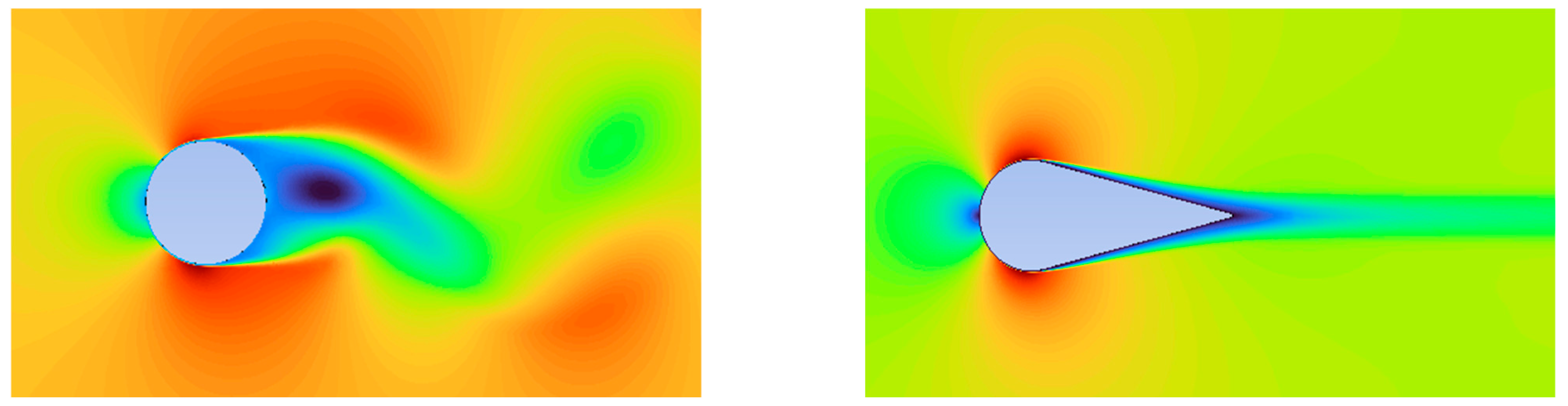
Fairings offer a particularly effective solution as streamlined appendages designed to mitigate flow separation. They primarily target the reduction of wake-induced pressure drag (Figure 5), which constitutes a significant portion of the total resistance experienced by bluff floating structures at towing Reynolds numbers. By reducing this pressure drag, fairings can lower the overall hydrodynamic resistance acting on the platform during transit. Preliminary CFD simulations conducted on the VolturnUS-S platform indicate that the rectangular pontoon is the primary contributor to the overall hydrodynamic drag. The results suggest that the installation of fairings on the rectangular pontoon section has the potential to achieve drag reductions of up to approximately 40% when compared with the baseline configuration. This drag reduction is achieved through the installation of a cylindrical leading-edge fairing at the front of the pontoon, combined with a streamlined rear appendage that promotes attached flow and reduces wake formation. These findings highlight the importance of conducting detailed investigations into such fairing concepts, which demonstrate significant potential for hydrodynamic drag mitigation. This reduction in resistance has several important implications.
First, for a given towing power, higher towing speeds may be achieved, enabling faster transit to the installation site. Reduced transit time, in turn, decreases the number of operating hours required from tug vessels, thereby lowering total towing costs. Alternatively, towing operations may be conducted at lower power levels while maintaining the same transit duration, resulting in reduced fuel consumption and lower CO2 emissions, particularly if tug engines are operated closer to their optimal efficiency range.
In addition to drag reduction, fairings can provide additionalbuoyancy, increasing the effective displacement of the FOWT. This added buoyancy may allow the platform to operate at a reduced draught during port operations, which is particularly advantageous given the draught limitations of many existing harbours. Improved port accessibility represents a logistical benefit, potentially expanding the range of suitable assembly ports for FOWT deployment.
Collectively, these advantages underscore the importance of developing effective drag-reduction strategies as an enabling technology for FOWTs, which are not inherently optimised for towing in their current designs. Drag reduction has long been a focus across multiple engineering disciplines, with applications spanning automotive, rail, and maritime sectors. While the specific implementations differ, the underlying objective remains consistent: to reduce resistance, improve energy efficiency, and lower the power required for motion through a fluid.
For a drag-reduction method to be considered applicable to FOWTs, it must satisfy two fundamental criteria: it must deliver a measurable reduction in hydrodynamic drag; and it must not compromise, and preferably should enhance, the stability of the floating platform. Among the various strategies available, fairings represent one of the most robust and transferable solutions. They belong to the class of passive drag-reduction devices, requiring no external energy input while offering substantial efficiency gains. It is important to note, however, that streamlining is beneficial primarily for bluff bodies operating at high Reynolds numbers, where flow separation dominates the drag contribution. At low Reynolds numbers, drag is largely governed by viscous effects, and streamlining may increase wetted surface area and thus total drag. Consequently, inappropriate or poorly designed streamlining can be counterproductive, leading to increased resistance rather than its reduction [29].

4.2. Knowledge Gap and Drag-Reduction Technologies in Other Industries

A significant knowledge gap exists regarding the implementation of drag-reduction systems (DRSs) for FOWTs to achieve the performance advantages mentioned previously. To address the limited research concerning drag-reduction strategies specifically for offshore floating structures, a cross-industry review was conducted, focusing on fairings and passive flow-control devices applied to bluff bodies.
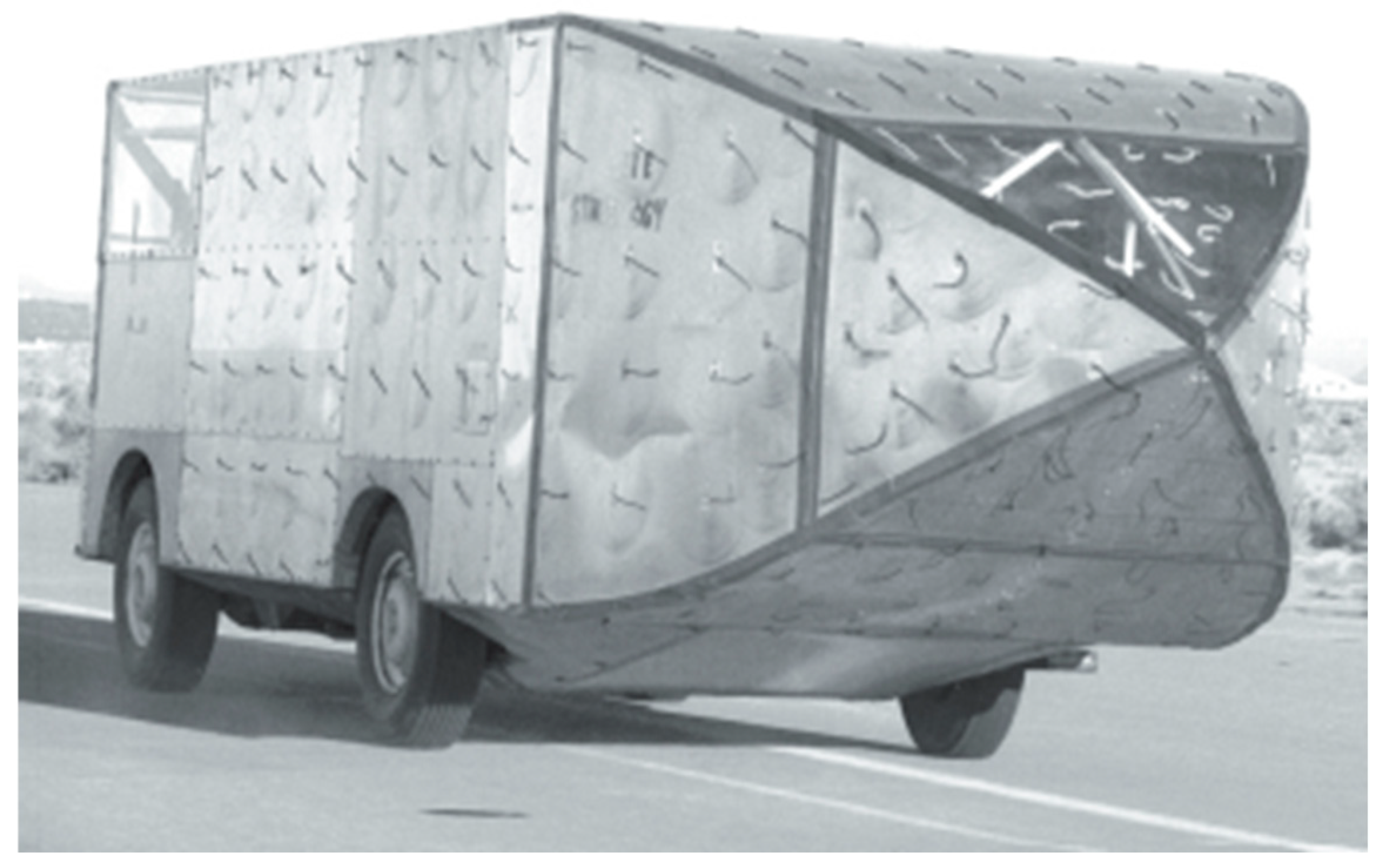
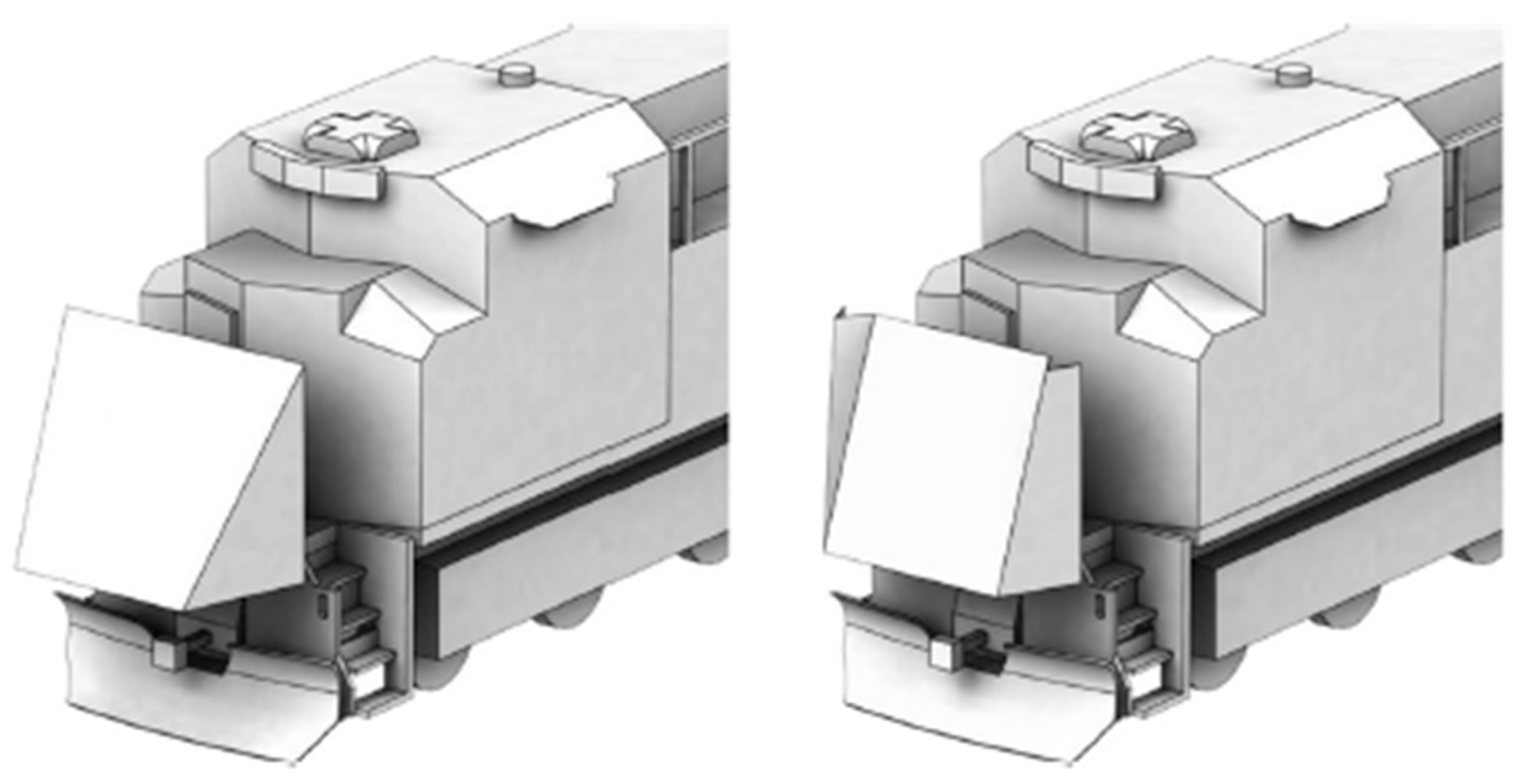
In land transport, particularly in heavy-duty trucking, aerodynamic drag constitutes a major component of energy consumption at cruising speeds. This has driven the development of retrofittable drag-reduction devices that minimise wake-induced pressure losses without requiring extensive structural modifications. Rear-end fairings, such as boat tails (Figure 6), have demonstrated significant effectiveness, with optimised geometries delaying flow separation and achieving drag reductions of up to 32% [45]. Additional devices, including vortex generators, underbody flow-management systems, and cross-flow vortex traps, further stabilise the wake and increase base pressure, yielding combined drag reductions approaching 30% and fuel savings of approximately 10% under operational conditions [46]. Similar design principles have been successfully applied to freight locomotives (Figure 7), where deployable, origami-inspired nose fairings achieved drag reductions in the range of 13.8–17.3%, as confirmed by both CFD simulations and wind tunnel experiments [47].
Drag reduction within the maritime sector is often directed towards mitigating wave resistance by utilising a bulbous bow. Le et al. [48] employed CFD simulations to assess the benefits of fitting a Non-Ballast Water Ship with a developed bulbous bow compared to a conventional blunt bow. In calm water, the bulbous bow reduced total resistance by up to 6%; while this modification slightly increased frictional resistance due to a larger wetted surface area, it was outweighed by a significant decrease in pressure resistance. The advantages were notably pronounced in wave conditions, where the bulbous bow improved seakeeping by reducing added wave resistance by 48% and total resistance by 13% [48].

4.3. Challenges in Implementing Fairings on FOWTs

Despite their potential benefits, the implementation of fairings on FOWTs presents several significant challenges. First, FOWT platforms exhibit substantial geometric diversity, and a single fairing design is unlikely to be universally applicable. For example, the OC4 semi-submersible consists of three large cylindrical columns, whereas the VolturnUS-type platform comprises multiple columns interconnected by large rectangular pontoons, supporting a central column that houses the turbine tower. In such cases, drag-reduction solutions may need to address not only cylindrical members but also prismatic and rectangular structural components. Consequently, fairings must be tailored to the specific geometry and dimensions of each platform type, limiting their direct adaptability.
A second challenge concerns the handling, attachment, and removal of large-scale fairings. Given their size, it is envisaged that fairings would be installed while the FOWT is in port using large machinery. The platform would then be towed to the installation site with the fairings attached. However, during the reverse towing route, the fairings may need to be assembled or reattached on site. Therefore, it is important that the attachment of the fairings can be performed easily at the installation site under offshore conditions.
If this is not feasible, one may consider fairings that remain attached for the lifetime of the FOWT, such that installation occurs only onshore. While this approach simplifies offshore operations, it may reduce the environmental feasibility of the fairings, as a dedicated set would be required for each FOWT. This would increase manufacturing demand and associated environmental loads, as well as overall costs.
In the reusable fairing concept, the fairings would be removed at the installation site and transported back for use on subsequent units. This operational approach imposes strict requirements on the detachment mechanisms, which must allow rapid and reliable removal during offshore operations. If the fairings are designed to be buoyant, their recovery and relocation could be achieved without dedicated barges, further reducing logistical complexity and cost.
Manufacturability of these drag-reduction fairings represents an additional constraint. Owing to their large dimensions, fairings would require dedicated manufacturing facilities and careful consideration of land transport and handling. It is anticipated that fairings would be made out of steel, a material that is used for various FOWT structures such as the UMaine VolturnUS-S platform [28]. By 2024, an average of around 2.18 tonnes of CO2 was emitted during the production of every tonne of steel [49]. Therefore, each fairing design is expected to have different emissions associated with its production and manufacturing due to different designs and material usage. Consequently, it is essential to carry out extensive research regarding the carbon emissions associated with fairing manufacture, transport, and installation to ensure that the embodied carbon associated with the fairing does not outweigh the emissions savings achieved during towing operations. A holistic life-cycle assessment is thus a prerequisite for their large-scale adoption.
Finally, implementing drag-reduction technologies such as fairings on existing FOWTs presents a significant design challenge, as these modifications inevitably alter the platform’s mass distribution and restoring forces, potentially compromising stability, both static and dynamic stability. Consequently, any proposed solution must strictly adhere to established standards, such as DNVGL-ST-0019, ensuring that the structure maintains sufficient restoring capacity, quantified by parameters like metacentric height (GM) and righting arm (GZ) curves, under both intact and damaged conditions [19]. Specifically for semi-submersibles, these regulations dictate that the righting moment must remain positive up to the second intercept and that the area under the righting moment curve must be at least 130% of the area under the wind heeling moment curve, guaranteeing the platform can resist capsizing [19]. The effects in dynamic stability of the structure with the added fairings also needs to be carefully considered to determine the behaviour of the platform during the towing process and different weather conditions such as waves.

5. Conclusions

The large-scale deployment of FOWTs represents a critical pathway for expanding offshore renewable energy into deep water regions where fixed bottom solutions are no longer viable. Among the available floating concepts, semi-submersible platforms have emerged as the most mature and widely adopted technology. However, as demonstrated in this paper, the wet towing of such platforms remains a significant technical, economic, and environmental challenge, primarily due to the high hydrodynamic drag associated with their bluff-body geometries. As turbine ratings continue to increase and platform dimensions scale accordingly, towing resistance is becoming an increasingly dominant factor influencing achievable towing speeds, fuel consumption, greenhouse gas emissions, and overall project costs.
This paper has highlighted the limitations of existing industry guidelines and empirical methods in accurately capturing the hydrodynamic behaviour of modern FOWTs platforms during towing. While computational fluid dynamics and experimental testing offer improved fidelity, both approaches face inherent constraints related to computational cost, scaling effects and the limited availability of full-scale validation data. Furthermore, towing-related emissions and costs, which are often underrepresented in lifecycle assessments, can constitute a non-negligible contribution to the overall environmental footprint and LCOE of floating wind projects, particularly when repeated tow to port operations for major maintenance are considered. This has become increasingly relevant in the context of emerging international requirements for the assessment and reduction of emissions from marine operations.
In this context, drag-reduction technologies, particularly passive solutions such as fairings, are identified as a promising and largely underexplored opportunity to improve towing efficiency. By mitigating wake-induced pressure drag, such technologies can either increase towing speeds for faster transit or reduce the power levels required from tug vessels, directly lowering fuel costs and the overall LCOE. Reduced engine loading also results in lower fuel consumption and associated emissions, supporting alignment with evolving IMO greenhouse gas guidelines.
Nevertheless, the implementation of drag-reduction systems on FOWT platforms introduces important challenges related to platform-specific geometry, structural integration, installation and removal logistics, stability requirements, and lifecycle emissions. Addressing these challenges will require targeted research that combines high fidelity numerical modelling, carefully designed experimental validation, and holistic lifecycle assessments to ensure that any drag-reduction solution delivers net economic and environmental benefits.
Ultimately, improving the hydrodynamic efficiency of towing operations should be regarded as an enabling requirement for the commercial-scale deployment of floating offshore wind rather than a marginal optimisation. By reducing towing resistance, fuel consumption, and emissions, effective drag-reduction strategies have the potential to enhance economic viability while supporting compliance with increasingly stringent maritime decarbonisation objectives.
To facilitate the sustainable expansion of FOWTs at scale, future research efforts must focus on the following key objectives:
  • Quantify the different drag components acting on different FOWT platform designs and determine which are the most prominent drag components.
  • Quantify the wave making resistance component during FOWT towing to determine if this can be ignored during towing simulations, hence allowing for less computationally demanding modelling.
  • Identify critical areas in FOWT platforms which are subject to the highest drag generation to determine critical areas of improvement for significant drag reduction.
  • Develop, validate, and benchmark diverse range of passive and active drag-reduction concepts that can be integrated, either permanently or temporarily, onto current FOWT platforms.
  • Investigate alternative drag-reduction strategies, such as optimising towing draft, modifying surface textures or materials to minimise viscous drag, and adapting proven hydrodynamic drag-reduction technologies from other industries onto FOWTs. A comparison analysis of the costs and carbon reduction should then be conducted to quantify the potential of these alternative measures when compared to the baseline FOWT model.
  • Establish methodologies for reliable experimental testing that accurately simulate the hydrodynamic realities of full-scale FOWT towing operations.
  • Stability analysis, both static and dynamic, of the effects of adding fairings to such platforms.
  • Create a detailed framework specifically for FOWT towing, focusing on logistical optimisation to minimize carbon emissions.
  • Embed drag-reduction consideration directly into the design phase of next-generation FOWT platforms.
Allocating significant resources, both financial and temporal, to research efforts globally is a critical requirement which is not only essential for the commercialization of FOWT technology but also for ensuring the industry contributes effectively to the global push for sustainable renewable energy.

Funding

This research is part of the TowFOWT Project funded by Xjenza Malta and the Ministry of Science and Technology of China (MOST) through the SINO-MALTA Fund 2024 Call (SINO-MALTA-2024-08) and the National Key R&D Program of China (No. 2025YFE0110400).

Conflicts of Interest

The authors declare no conflicts of interest.

Abbreviations

The following abbreviations are used in this manuscript:
AHTSAnchor Handling Tug Supply
CCSChina Classification Society
CFDComputational Fluid Dynamics
COBCentre of Buoyancy
COGCentre of Gravity
DNVDet Norske Veritas
DRSDrag-Reduction System
FOWTFloating Offshore Wind Turbine
GWECGlobal Wind Energy Council
IECInternational Electrotechnical Commission
IMOInternational Maritime Organization
ISOInternational Organization for Standardization
ITTCInternational Towing Tank Conference
LCOELevelised Cost of Energy
LESLarge Eddy Simulation
O&GOil and Gas
RANSReynolds Averaged Navier Stokes
ROVRemotely Operated Vehicle
TLPTension Leg Platform
TRLTechnology Readiness Level
URANSUnsteady Reynolds Averaged Navier–Stokes

References

  1. Backwell, B.; Clarke, E.; Ladwa, R.; Mullin, S.; Jayasurya, F.; Hutchinson, M.; Qiao, L.; Williams, R.; Han, W.; Liang, W.; et al. GWEC|Global Wind Report 2025, Clean. 2025. Available online: https://26973329.fs1.hubspotusercontent-eu1.net/hubfs/26973329/2.%20Reports/Global%20Wind%20Report/GWEC%20Global%20Wind%20Report%202025.pdf (accessed on 10 December 2025).
  2. Williams, R.; Zhao, F.; Melkonyan, N.; Hutchinson, M.; Cheong, J. Global Offshore Wind Report 2025, Lisbon, Portugal. 2025. Available online: https://gowa-energy.org/publication/global-offshore-wind-report-2025 (accessed on 10 December 2025).
  3. Global Wind Energy Council. Floating Offshore Wind-A Global Opportunity; Global Wind Energy Council: Lisbon, Portugal, 2022. [Google Scholar]
  4. Leimeister, M.; Kolios, A.; Collu, M. Critical review of floating support structures for offshore wind farm deployment. In Journal of Physics: Conference Series; Institute of Physics Publishing: Bristol, UK, 2018. [Google Scholar] [CrossRef]
  5. Floating Wind: Anchoring the Next Generation Offshore; RenewableUK: London, UK, 2024.
  6. Ramachandran, R.C.; Desmond, C.; Judge, F.; Serraris, J.J.; Murphy, J. Floating Wind Turbines: Marine Operations Challenges and Opportunities; Copernicus Publications: Göttingen, Germany, 2022. [Google Scholar] [CrossRef]
  7. Jiang, Z. Installation of offshore Wind Turbines: A Technical Review; Elsevier Ltd.: London, UK, 2021. [Google Scholar] [CrossRef]
  8. Roberts, A.; Le Pivert, F.; Kazemi, S.; Tosdevin, T.; López-Santander, A.; Craven, M.J.; Johanning, L. Scale model and ship simulator towing of the IEA 15 MW wind turbine on the UMaine VolturnUS-S platform. Ocean. Eng. 2025, 336, 121732. [Google Scholar] [CrossRef]
  9. Ramzanpoor, I.; Nuernberg, M.; Tao, L. Benchmarking study of 10 MW TLB floating offshore wind turbine. J. Ocean Eng. Mar. Energy 2023, 10, 1–34. [Google Scholar] [CrossRef]
  10. IRENA. Floating Offshore Wind Outlook. IRENA: Abu Dhabi, United Arab Emirates, 2024. Available online: www.irena.org (accessed on 12 December 2025).
  11. Schilling, M.; Borisade, F.; Ren, X.; Tiedemann, S.; Bailey, T.; Amiot, P.; Espelage, J.; Scheffler, R.; Davis, J.; Aliyar, S.; et al. D4.5 Floating Wind Installation Strategies; RAMBOLL: Copenhagen, Denmark, 2023. [Google Scholar]
  12. Photo Gallery—Offshore Wind California. Available online: https://www.offshorewindca.org/photo-gallery (accessed on 20 January 2026).
  13. DNVGL-ST-N001; Marine Operations and Marine Warranty. DNV: Høvik, Norway, 2023.
  14. ISO 29400; Ships and Marine Technology—Offshore Wind Energy—Port and Marine Operations. International Organisation for Standardisation: Geneva, Switzerland, 2020.
  15. Guidelines for Safe Ocean Towing; International Maritime Organization: London, UK, 1998.
  16. IEC 61400-3-2; Wind Energy Generation Systems—Part 3-2: Design Requirements for Floating Offshore Wind Turbines. International Electrotechnical Commission (IEC): Geneva, Switzerland, 2025.
  17. Apollo & Global Energy Group, PR45 Project Tow to Port Offstation Management Public Report. 2024. Available online: https://fowcoe.co.uk/ (accessed on 13 December 2025).
  18. Yin, D.; Indergård, R.; Lie, H.; Braaten, H. Experimental Investigation of Towing of a Semi-submersible Floating Offshore Wind Turbine. In Journal of Physics: Conference Series; Institute of Physics: London, UK, 2024. [Google Scholar] [CrossRef]
  19. DNVGL-ST-0119; Floating Wind Turbine Structures. DNV: Høvik, Norway, 2018. Available online: http://www.dnvgl.com (accessed on 13 December 2025).
  20. Hancox, M. Towing; Oilfield Publications Ltd.: Ledbury, UK, 1994. [Google Scholar]
  21. Ramachandran, R.C.; Serraris, J.J.; de Ridder, E.J.; Desmond, C.; Murphy, J. An analysis of floating wind turbine towing operations using OpenFAST. In Journal of Physics: Conference Series; Institute of Physics: London, UK, 2024. [Google Scholar] [CrossRef]
  22. Maritime CO2 Emissions; IMO: London, UK, 2020.
  23. Riviera—News Content Hub—Green AHTS is also a Powerful Subsea Constructor. Available online: https://www.rivieramm.com/news-content-hub/news-content-hub/green-ahts-is-also-a-powerful-subsea-constructor-46064?utm_source=chatgpt.com (accessed on 23 September 2025).
  24. White, F.M. Chapter 7—Flow Past Immersed Bodies. In Fluid Mechanics, 7th ed.; McGraw-Hill: Columbus, OH, USA, 2011; Chapter 7; pp. 482–500. [Google Scholar]
  25. Vestas Wind Systems A/S, ‘V236-15.0 MWTM’, 2025. Available online: https://www.vestas.com/en/energy-solutions/offshore-wind-turbines/V236-15MW (accessed on 20 December 2025).
  26. The SG 14-236: Powering change. Available online: https://www.siemensgamesa.com/global/en/home/products-and-services/offshore/wind-turbine-sg-14-236-dd.html (accessed on 20 December 2025).
  27. The Qihang 20MW Floating Offshore Wind Turbine Successfully Installed. Available online: https://www.crrcgc.cc/en/2025-02/13/article_2025021317225881058.html (accessed on 16 December 2025).
  28. Allen, C.; Viselli, A.; Dagher, H.; Goupee, A.; Gaertner, E.; Abbas, N.; Hall, M.; Barter, G. Definition of the UMaine VolturnUS-S Reference Platform Developed for the IEA Wind 15-Megawatt Offshore Reference Wind Turbine Technical Report. 2020. Available online: www.nrel.gov/publications (accessed on 5 December 2025).
  29. Çengel, Y.A.; Cimbala, J.M. Fluid Mechanics Fundamentals and Applications, 3rd ed.; McGraw-Hill: Columbus, OH, USA, 2013. [Google Scholar]
  30. Hancox, M. The Oilfield Seamanship Series: Volume 4—Towing; Oilfield Publications Ltd.: Ledbury, UK, 1994. [Google Scholar]
  31. 2024 Guidelines on Life Cycle GHG Intensity of Marine Fuels, Guidelines for Towage at Sea; International Maritime Organization (IMO): London, UK, 2011.
  32. Gao, P.; Yuan, X.; Liu, S.; Lin, W.; Chen, M.; Wang, Z.; Tang, Y.; Jiang, X. Towing Resistance and Design of a Towing Scheme for a Floating Wind Turbine. J. Mar. Sci. Eng. 2025, 13, 789. [Google Scholar] [CrossRef]
  33. Schiestel, R.; Chaouat, B. Turbulence modeling and simulation advances in CFD during the past 50 years. Comptes Rendus Mec. 2022, 350, 23–51. [Google Scholar] [CrossRef]
  34. International Towing Tank Conference (ITTC). ITTC Recommended Procedures and Guidelines: Resistance Test—1978 ITTC Perfor-mance Prediction Method; ITTC: Wuxi, China, 2017. [Google Scholar]
  35. International Towing Tank Conference (ITTC). ITTC-Recommended Procedures and Guidelines Model Tests for Offshore Wind Turbines; ITTC: Nantes, France, 2021. [Google Scholar]
  36. Chen, M.; Chen, Y.; Li, T.; Tang, Y.; Ye, J.; Zhou, H.; Ouyang, M.; Zhang, X.; Shi, W.; Sun, X. Analysis of the wet-towing operation of a semi-submersible floating wind turbine using a single tugboat. Ocean Eng. 2024, 299, 117354. [Google Scholar] [CrossRef]
  37. 2023 IMO Strategy on Reduction of GHG Emissions from Ships; International Maritime Organization (IMO): London, UK, 2023.
  38. Maritime Organization. 2024 Guidelines on Life Cycle GHG Intensity of Marine Fuels; International Maritime Organization (IMO): London, UK, 2024. [Google Scholar]
  39. WindFloat Atlantic Wind Plus. Available online: https://windfloat-atlantic.com/ (accessed on 16 December 2025).
  40. BOURBON ORCA DP2 Anchor Handling Tug Supply Vessel 183 Metric Ton Bollard Pull 400 Metric Ton Line Pull Winch. 2006. Available online: https://wwwcdn.imo.org/localresources/en/KnowledgeCentre/IndexofIMOResolutions/MEPCDocuments/MEPC.391(81).pdf (accessed on 16 December 2025).
  41. Wärtsilä. Wärtsilä 32: Product Guide; Wärtsilä Ship Power Technology: Vaasa, Finland, 2013. [Google Scholar]
  42. EPA. Greenhouse Gas Emissions from a Typical Passenger Vehicle. Available online: https://www.epa.gov/greenvehicles/greenhouse-gas-emissions-typical-passenger-vehicle (accessed on 16 December 2025).
  43. Kausche, M.; Adam, F.; Dahlhaus, F.; Großmann, J. Floating offshore wind—Economic and ecological challenges of a TLP solution. Renew. Energy 2018, 126, 270–280. [Google Scholar] [CrossRef]
  44. Wiser, R.; Jenni, K.; Seel, J. Lawrence Berkeley National Laboratory Recent Work Title Forecasting Wind Energy Costs and Cost Drivers: The Views of the World’s Leading Experts. Available online: https://escholarship.org/uc/item/0s43r9w4 (accessed on 16 December 2025).
  45. Gelzer, C. Fairing Well. From Shoebox to Bat Truck and Beyond: Aerodynamic Truck Research at NASA’s Dryden Flight Research Center; National Aeronautics and Space Administration: Washington, DC, USA, 2011. [Google Scholar]
  46. Wood, R.M.; Bauer, S.X.S. Simple and Low-Cost Aerodynamic Drag Reduction Devices for Tractor-Trailer Trucks; SAE International: Warrendale, PA, USA, 2003. [Google Scholar]
  47. Stucki, C.L.; Maynes, D. Drag reducing nose fairings for existing freight train locomotives. Adv. Aerodyn. 2022, 4, 37. [Google Scholar] [CrossRef]
  48. Le, T.K.; Van He, N.; Van Hien, N.; Bui, N.T. Effects of a bulbous bow shape on added resistance acting on the hull of a ship in regular head wave. J. Mar. Sci. Eng. 2021, 91, 559. [Google Scholar] [CrossRef]
  49. World Steel Association. Climate Change and the Production of Iron and Steel; World Steel Association: Brussels, Belgium, 2025. [Google Scholar]
Figure 2. 9.5 MW turbine being towed to Scotland (photo courtesy of Principle Power) [12].
Energies 19 00797 g002
Figure 3. Single- and double-column facing forwards towing configuration.
Energies 19 00797 g003
Figure 4. Multiple tug configuration for the towing operation.
Energies 19 00797 g004
Figure 5. Wake behind a cylindrical 2D body (left) and an introduction of a streamline appendage (right).
Energies 19 00797 g005
Figure 6. Boat tail-type rear-end fairing [45].
Energies 19 00797 g006
Figure 7. Fairing application in locomotives [47].
Energies 19 00797 g007
Disclaimer/Publisher’s Note: The statements, opinions and data contained in all publications are solely those of the individual author(s) and contributor(s) and not of MDPI and/or the editor(s). MDPI and/or the editor(s) disclaim responsibility for any injury to people or property resulting from any ideas, methods, instructions or products referred to in the content.