


Abstract
Photovoltaic thermal systems are capable of simultaneously generating electricity and recovering thermal energy from the rear surface of photovoltaic modules. When integrated with an air-source heat pump, the thermal energy recovered from an air-based photovoltaic thermal system can be utilized as an auxiliary heat source, thereby improving heating performance and reducing electricity consumption. In this study, a demonstration-scale performance assessment of an air-based photovoltaic thermal-assisted air-source heat pump system was conducted in a real building located in Asan, South Korea. Performance analysis was based on measured operational data collected over a one-month period in March 2024, corresponding to late-winter to early-spring conditions when heating demand was still present. During the measurement period, the average plane-of-array solar irradiance was approximately 600 W/m2, with peak values reaching up to 1000 W/m2. Under these conditions, the air-based photovoltaic thermal collector provided average electrical and thermal power outputs of 1.96 kW and 2.2 kW, respectively, while peak outputs reached 3.3 kW for electricity generation and 3.8 kW for thermal energy recovery. The daily thermal energy production remained relatively stable, ranging from 17.8 to 21.7 kWh. Furthermore, approximately 45–60% of the recovered thermal energy was effectively transferred to a buffer tank through an air-to-water heat exchanger, indicating stable solar heat recovery and storage performance. When the recovered thermal energy was supplied to the air-source heat pump during daytime heating operation, a preheating effect was observed, resulting in reduced electricity consumption and improved heating performance. The coefficient of performance increased from 2.24 during nighttime operation to 2.81 under solar-assisted daytime conditions, corresponding to a notable reduction in electricity consumption under solar-assisted daytime operation, compared with nighttime operation without PVT preheating. Overall, the results indicate that, under the tested late-winter to early-spring heating conditions, the integrated air-based photovoltaic thermal and air-source heat pump system can enhance heating performance and reduce electricity consumption, demonstrating its practical feasibility as a solar-assisted heating solution rather than representing generalized annual performance.
1. Introduction
In recent decades, the frequency of natural disasters such as sea level rise, heat waves, and heavy rainfall has been increasing due to global warming, highlighting the urgent need to reduce greenhouse gas (GHG) emissions. According to the Special Report on Global Warming of 1.5 °C published by the Intergovernmental Panel on Climate Change (IPCC) in 2018, the global average temperature has already risen by approximately 1 °C compared to pre-industrial levels. The report projected that, if current emission trends continue, the global temperature could rise by more than 2 °C, resulting in severe and irreversible impacts on the climate system [1]. To mitigate these risks, the report emphasized the necessity of limiting global warming to below 1.5 °C and achieving carbon neutrality by 2050 [2]. In response, many countries have declared carbon neutrality and are implementing diverse policies to accelerate the transition from fossil fuels to renewable energy sources. For instance, the United States enacted the Inflation Reduction Act of 2022 (IRA), which provides investment tax credits (ITC) of up to 30–40% for solar and wind power projects, significantly strengthening incentives for renewable energy deployment [3]. The European Union (EU) has introduced major policy frameworks such as Fit for 55 and REPowerEU to expand the adoption of renewable energy and improve energy efficiency [4,5]. Similarly, South Korea announced its 2050 Carbon Neutrality Declaration in 2020 and established the Renewable Energy 3020 Implementation Plan, which aims to increase the share of renewable energy in total electricity generation to 20% by 2030. The government has also submitted its Nationally Determined Contribution (NDC) to reduce GHG emissions by 37% compared to the business-as-usual scenario by 2030 and has been implementing policies such as the Renewable Portfolio Standard (RPS) and the Zero Energy Building (ZEB) mandate to promote low-carbon development across sectors [6,7,8].
As a result, the importance of renewable energy technologies that can replace fossil fuels has been rapidly increasing. In particular, solar energy technologies that utilize both solar radiation and heat to produce electricity and thermal energy are gaining significant attention. Among these, the photovoltaic/thermal (PVT) system—a hybrid technology combining photovoltaic (PV) modules and solar thermal collectors—can simultaneously generate electricity and heat. The heat recovered from the rear surface of the PV module can be used as a thermal source for buildings, effectively preventing efficiency degradation due to PV module overheating [9,10]. PVT systems are generally classified according to their working fluid: air-based, liquid-based, and hybrid types. Air-based PVT systems, which use air as the heat transfer medium, offer several advantages over liquid-based systems, such as the absence of freezing and leakage issues, lower maintenance requirements, and easier integration with building HVAC systems [11]. Among various building HVAC technologies, heat pump systems have been recognized as environmentally friendly alternatives to conventional fossil-fuel boilers, as they utilize electricity instead of combustion-based fuels. According to the Net Zero by 2050 roadmap published by the International Energy Agency (IEA), the building sector should meet over 50% of its heating demand by using heat pumps by 2045 to achieve global carbon neutrality [12,13].
However, the performance of air-source heat pump (ASHP) systems tends to deteriorate under extremely low outdoor air temperatures during winter, leading to lower heating efficiency and increased compressor load. To address this issue, integrating an air-based PVT system with an ASHP can provide multiple benefits: the electricity generated by the PVT system can directly power the heat pump, while the recovered heat can be used as a supplementary heat source, thereby improving heating performance and reducing electricity consumption. Numerous studies have investigated the thermal and electrical performance of air-based PVT collectors and their integration with building energy systems. Several works evaluated the influence of baffle plate geometry, dual-channel configurations, and air mass flow rate on the performance of air-based PVT systems, demonstrating that increased airflow enhances electrical efficiency by lowering PV module temperature, while also improving thermal efficiency despite reduced temperature difference between inlet and outlet air [14,15,16]. Previous experimental studies have analyzed the effect of photovoltaic cell coverage ratio on the thermal and electrical efficiency of air-based PVT collectors [17,18]. In addition, computational fluid dynamics (CFD) simulations have been conducted to investigate the influence of internal geometric parameters, such as flow path configuration and turbulence-inducing structures, on the thermal characteristics of air-based PVT collectors, and optimized designs have been proposed to enhance thermal performance [19]. Despite these valuable contributions, several limitations can be identified in the existing literature. Many previous studies have primarily focused on laboratory-scale experiments or numerical simulations conducted under controlled conditions, which may not fully reflect the complex operational characteristics of real buildings. In addition, a substantial portion of existing experimental studies has concentrated on liquid-based PVT systems, while field-scale investigations of air-based PVT systems remain relatively limited. As a result, the practical performance and operational reliability of air-based PVT-assisted heating systems under real building conditions are not yet sufficiently verified.
Beyond collector-level investigations, several studies have explored the integration of PVT systems with building HVAC applications. For example, Kim et al. [20] developed an air-conditioning system connecting an air-based PVT collector to an air handling unit (AHU), and reported that the use of preheated PVT air as a heating source contributed to a reduction in heating energy demand in a mock-up test. Joo et al. [21] performed a bench-scale experiment by integrating a liquid-based PVT collector with an ASHP system for public building heating, reporting a 10.6% increase in the coefficient of performance (COP) compared to a conventional heat pump. In addition, Haliu et al. [22] and Kamel et al. [23] numerically analyzed the efficiency improvement of air-source heat pump systems when coupled with air-based PVT collectors, confirming the potential benefits of hybrid configurations. Although extensive studies have examined the improved performance of heat pump systems integrated with PVT collectors, most have focused on liquid-based PVT systems or simulation-based analyses. To date, few studies have performed demonstration-scale experiments using real building applications of air-based PVT systems coupled with air-source heat pumps. Furthermore, although several studies have investigated the integration of PVT systems with heat pump-based HVAC applications, most of them have been limited to bench-scale experiments or simulation-based analyses. Direct field measurements obtained from real buildings, particularly for air-based PVT systems coupled with air-source heat pumps, are still scarce. This gap makes it difficult to fully assess the actual heating contribution of air-based PVT systems and their impact on heat pump performance under realistic operating conditions.
However, most previous studies have been limited to laboratory-scale tests, numerical simulations, or liquid-based PVT configurations. Experimental evidence obtained from real building applications of air-based PVT-assisted heat pump systems remains scarce, particularly under actual winter operating conditions where ASHP performance typically deteriorates. Furthermore, few studies have quantified the direct heating contribution of air-based PVT collectors and its impact on the COP improvement of ASHPs using field-measured data. In this context, the innovation of the present study does not lie in achieving record high efficiency values, but rather in providing demonstration-scale field evidence of the operational performance of an air-based PVT-assisted air-source heat pump system in a real building. By focusing on field-measured data obtained under actual heating operation conditions, this study aims to complement existing laboratory- and simulation-based research and to enhance the practical understanding of PVT-assisted heat pump systems.
Therefore, this study conducted a demonstration-scale performance evaluation of an air-based PVT-assisted heat pump system installed in an actual building. Field measurements were used to analyze the thermal and electrical performance of the air-based PVT collector and the heating performance of the PVT-assisted air-source heat pump (ASHP). The results of this demonstration-scale performance evaluation provide (i) empirical evidence of the heating contribution of air-based PVT systems under real building conditions, (ii) a quantitative assessment of COP improvement during winter operation, and (iii) practical insights for the design and optimization of PVT-assisted heat pump systems for building applications.
Unlike previous studies mainly focused on simulations or liquid-based PVT systems, this study aims to experimentally evaluate the performance of an air-based PVT–air-source heat pump integrated system using measured data obtained from an actual building environment. The analysis is based on field measurements collected during a representative heating period (early spring, approximately one month), and comprehensive assessments under long-term operation or across different seasonal conditions are beyond the scope of this study. Accordingly, this study should be regarded as a case study focusing on real-building operation rather than a statistically generalized experimental campaign, and the findings are intended to provide practical insights rather than universal performance benchmarks.
2. Materials and Methods
2.1. Design and Configuration of the Air-Based PVT Collector
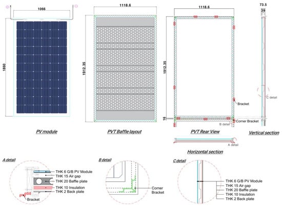
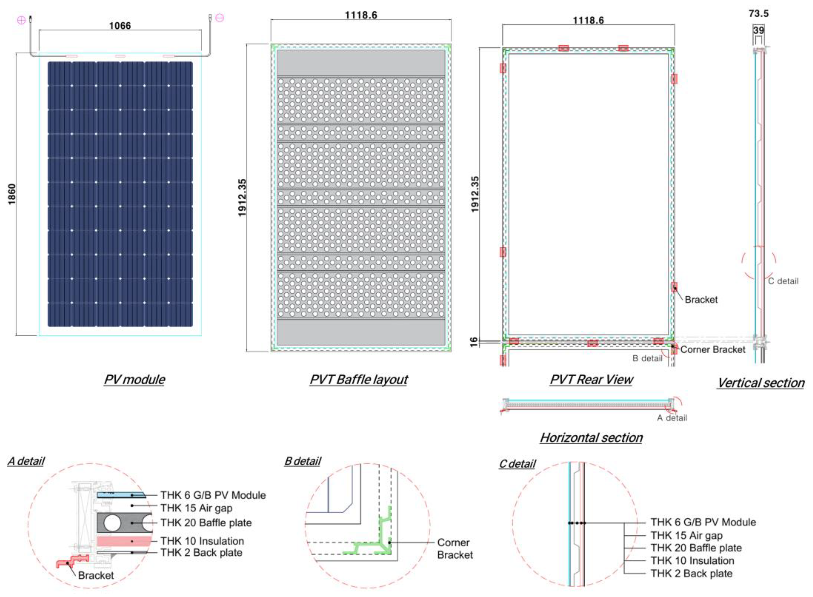
For this study, an air-based PVT (photovoltaic/thermal) collector was developed using a Glass-to-Backsheet (GtoB) type PV module at the front side. The PV module was custom-made for experimental purposes and fabricated by SKSE (Seoul, Republic of Korea). Inside the collector, a baffle plate was installed within the air channel to extend the air flow path, allowing the passing air to absorb more heat from the rear surface of the PV module. By lengthening the air flow path, the heat generated at the back of the PV module could be more effectively transferred to the airflow, thereby improving the collector’s thermal performance. The installed baffle plate was fabricated from a high thermal conductivity absorber sheet, which was perforated and bent to promote air turbulence within the channel. The induced turbulence enhanced convective heat transfer between the air and absorber surface, resulting in higher overall thermal efficiency. The frame of the air-based PVT collector was constructed using lightweight aluminum to ensure structural rigidity while minimizing weight. Figure 1 illustrates the configuration and structural composition of the developed air-based PVT collector.
Figure 1.
Structural configuration of the air-based PVT collector. The blue lines represent the outer boundary of the PV module and the collector frame, the gray shaded areas indicate the baffle plate, and the dashed black lines denote bracket slots, internal frame lines, and section lines. The circled regions (A, B, and C) highlight detailed structural components.
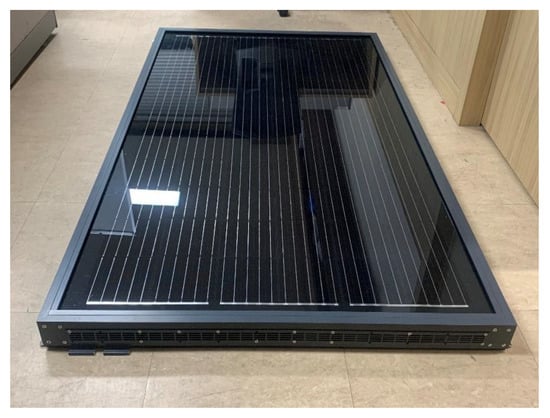
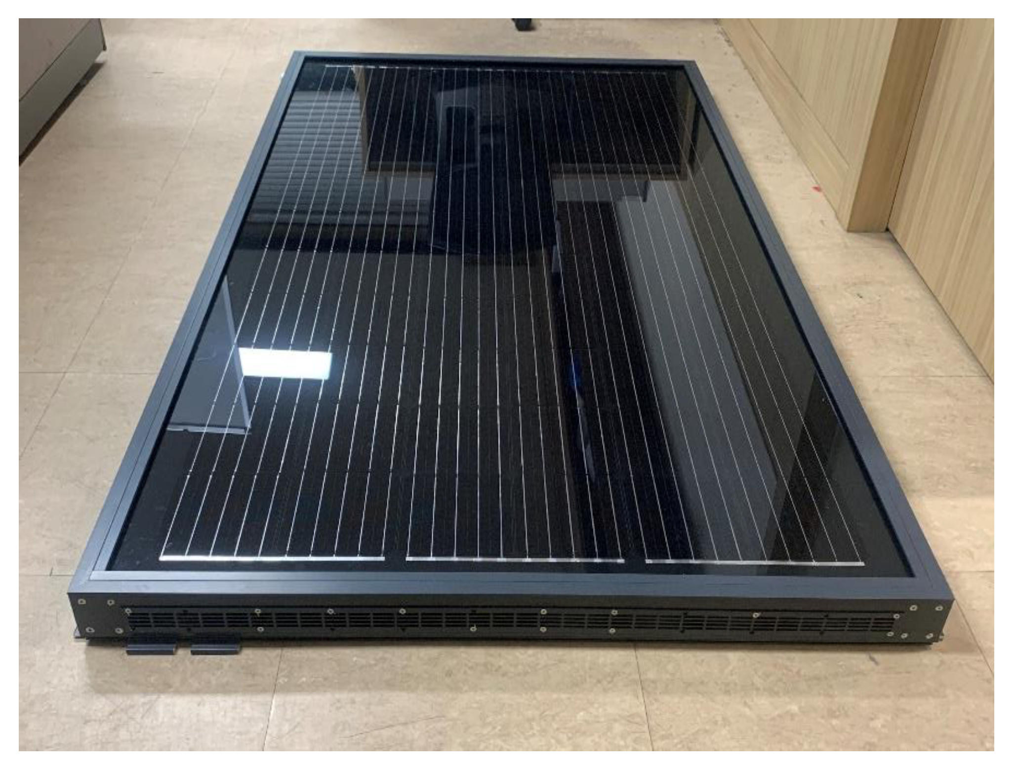
Figure 2 shows a photograph of the air-based PVT collector used in this study, and Table 1 summarizes the specifications of the PV module applied to the collector.
Figure 2.
Photograph of air-based PVT collector.
Table 1.
Electrical specifications of the PVT module at STC.
2.2. Description of the Air-Based PVT System and Installation
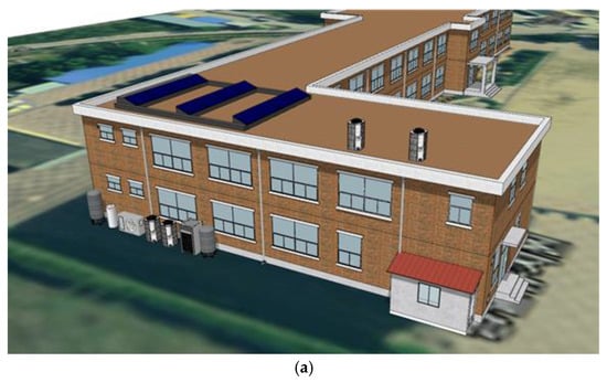
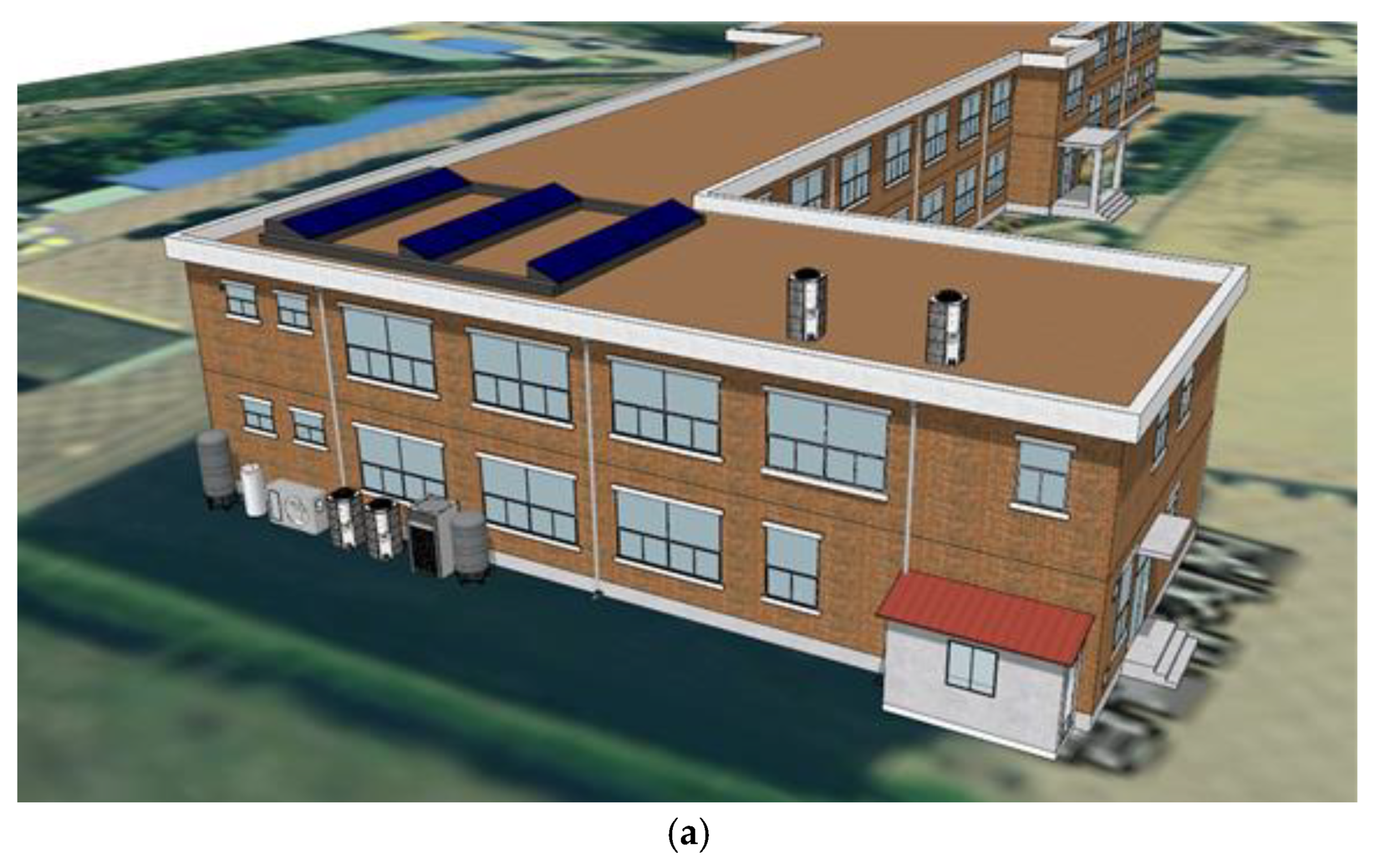
For this study, an air-source heat pump system integrated air-based PVT was installed at an elementary school located in Asan, Chungcheongnam-do, South Korea (36.88° N, 127.07° E). The air-based PVT system was mounted on the building rooftop, which had no surrounding shading obstacles, ensuring unobstructed solar exposure.
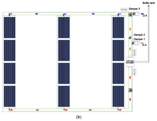
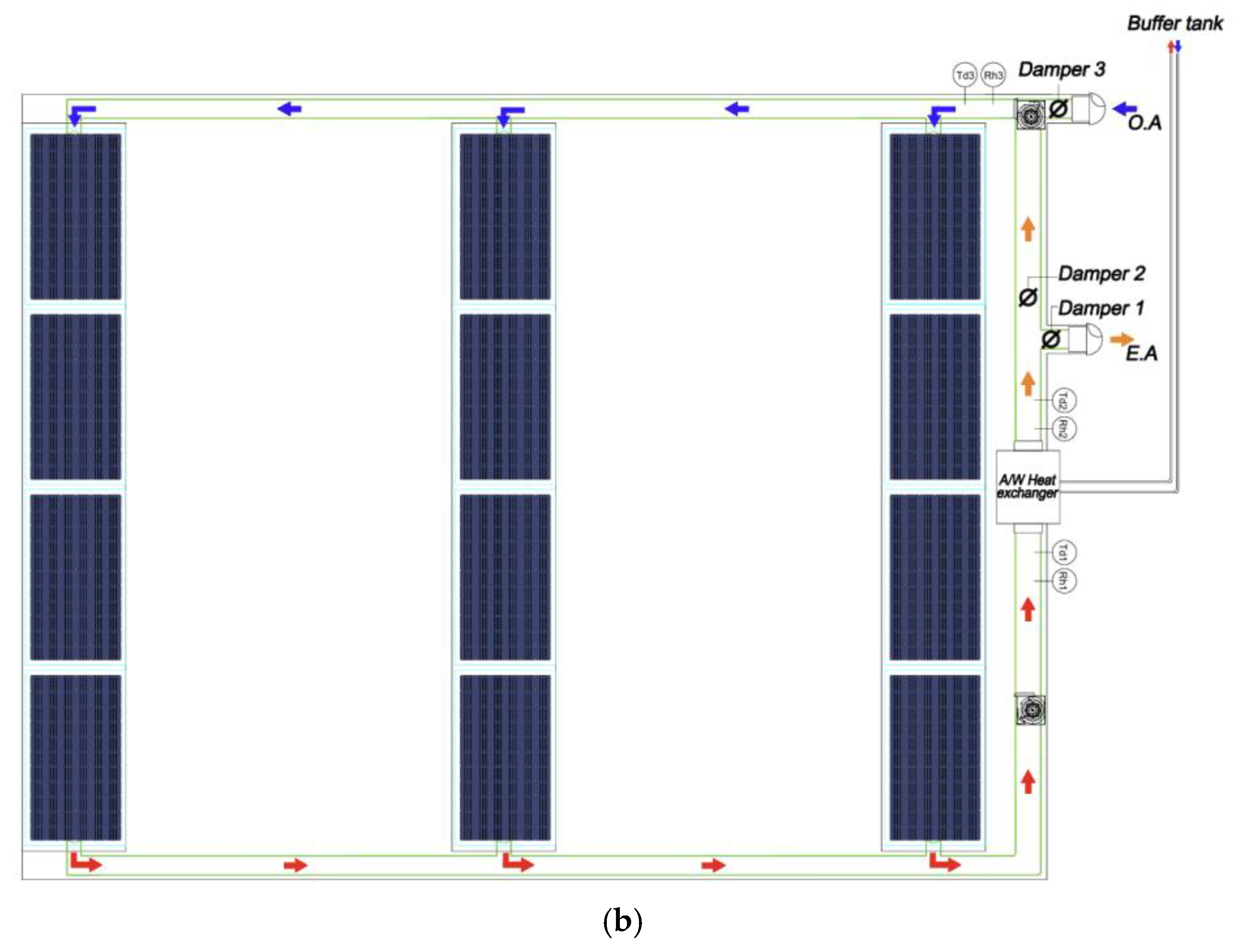
An overview of the rooftop installation of the air-based PVT system on the demonstration building is illustrated in Figure 3a, providing the spatial context of the system layout and module arrangement. The schematic diagram of the installed system configuration, including the collector array and airflow path, is presented in Figure 3b.
Figure 3.
(a) Overview of the rooftop installation of the air-based PVT system on the demonstration building; (b) schematic of the air-based PVT collector array and its connection to the air-to-water heat exchanger. The arrows indicate the airflow direction from the air-based PVT collector through the connected duct toward the air-to-water heat exchanger.
The air-based PVT system consisted of twelve PVT collectors, with a total installed electrical capacity of 3.82 kW. The collectors were arranged in three rows of four modules each, and each row was connected in series to increase the air flow path length within the system. By extending the air flow path through four connected collectors, the outlet air temperature could be increased, thereby enhancing the overall heat recovery performance.
A fan unit was installed to circulate air through the collectors and the connecting ducts. The preheated air from the PVT collector outlets was directed to an air-to-water heat exchanger, where heat transfer occurred between the PVT air stream and the working fluid of the thermal storage tank, enabling the storage of recovered solar heat. The inlet air temperature of the PVT collectors was controlled by a motorized damper system. Depending on the preset inlet temperature, the damper selectively supplied either outdoor air or return air from the heat exchanger to the PVT collector inlets. This configuration enabled stable temperature control and efficient utilization of solar heat under varying environmental conditions.
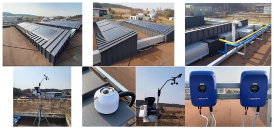
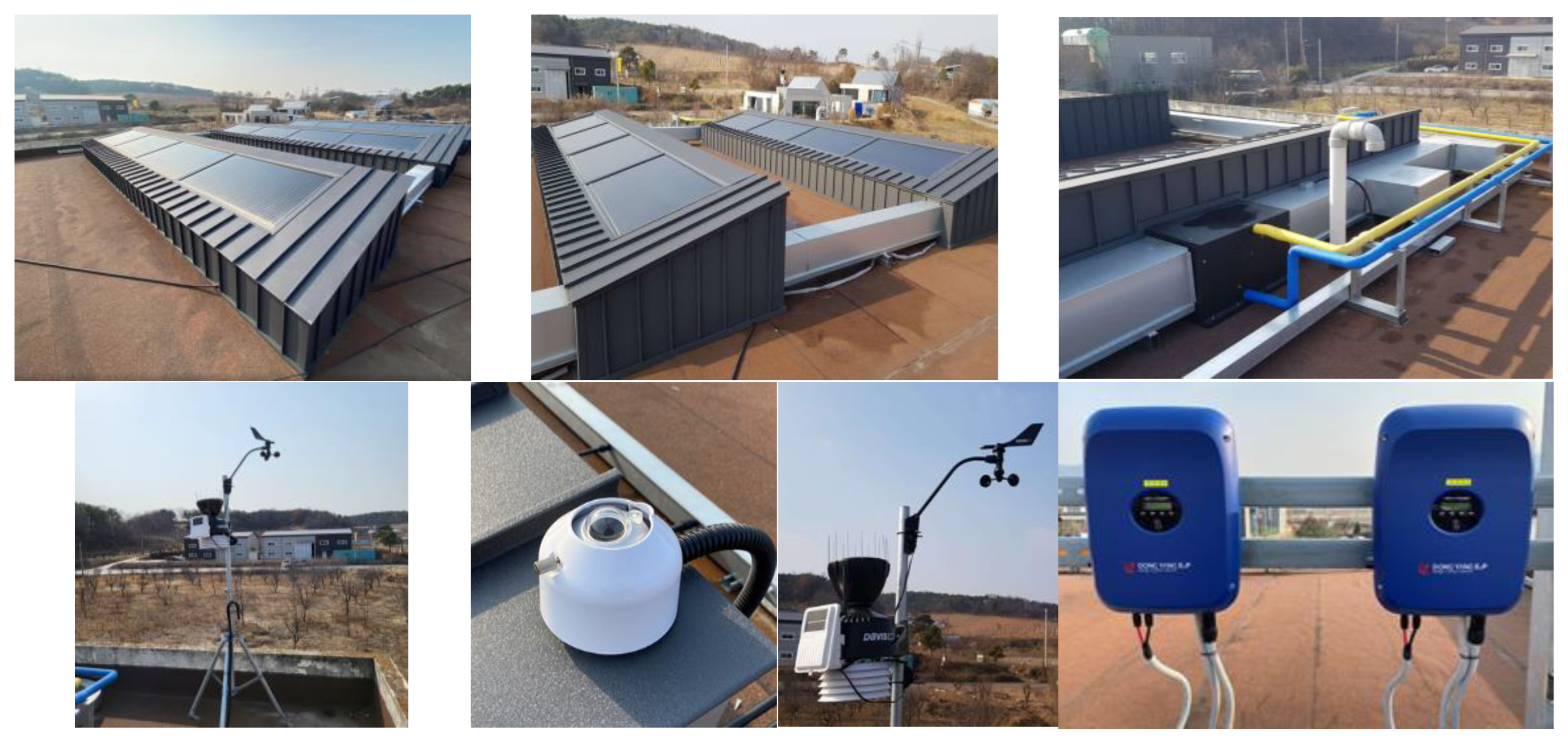
Figure 4 illustrates the installation of the air-based PVT system on the building rooftop. The PVT collectors were installed facing south with an inclination angle of 13°. To minimize shading effects caused by the mounting structure and to reduce potential power losses, uniform spacing was maintained between adjacent collectors. To limit thermal losses from the preheated air and the working fluid circulating between the PVT system and the buffer tank, thermal insulation was applied to all air ducts and piping.
Figure 4.
Installation overview of the air-based PVT system, including the PVT collectors, air ducting, heat exchanger, inverter, and weather station. (This figure was newly replotted based on the original experimental dataset, with reconfigured legends, axis ranges and scaling, and color schemes.)
The direct current electricity generated by the PVT system was converted to alternating current through an inverter, which was installed in a space adjacent to the rooftop. The inverter continuously monitored the operating status of the system and the electrical power generation, and the measured inverter output data were used for the electrical performance analysis of the PVT system. For the performance evaluation of the PVT system, several measurement instruments were installed, including a pyranometer, temperature and humidity transmitters, and a weather station. The pyranometer was mounted on the same tilted plane as the PVT collectors to measure the plane-of-array solar irradiance incident on the collector surfaces. Temperature and humidity transmitters were installed at the inlet and outlet of the PVT system, as well as at the outlet of the air-to-water heat exchanger, to monitor variations in air temperature and relative humidity. In addition, a weather station was installed on the rooftop to continuously record ambient dry-bulb temperature, relative humidity, wind direction, and wind speed, providing meteorological data for correlation with system performance.
2.3. Configuration of the Integrated Air-Source Heat Pump System
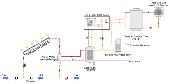
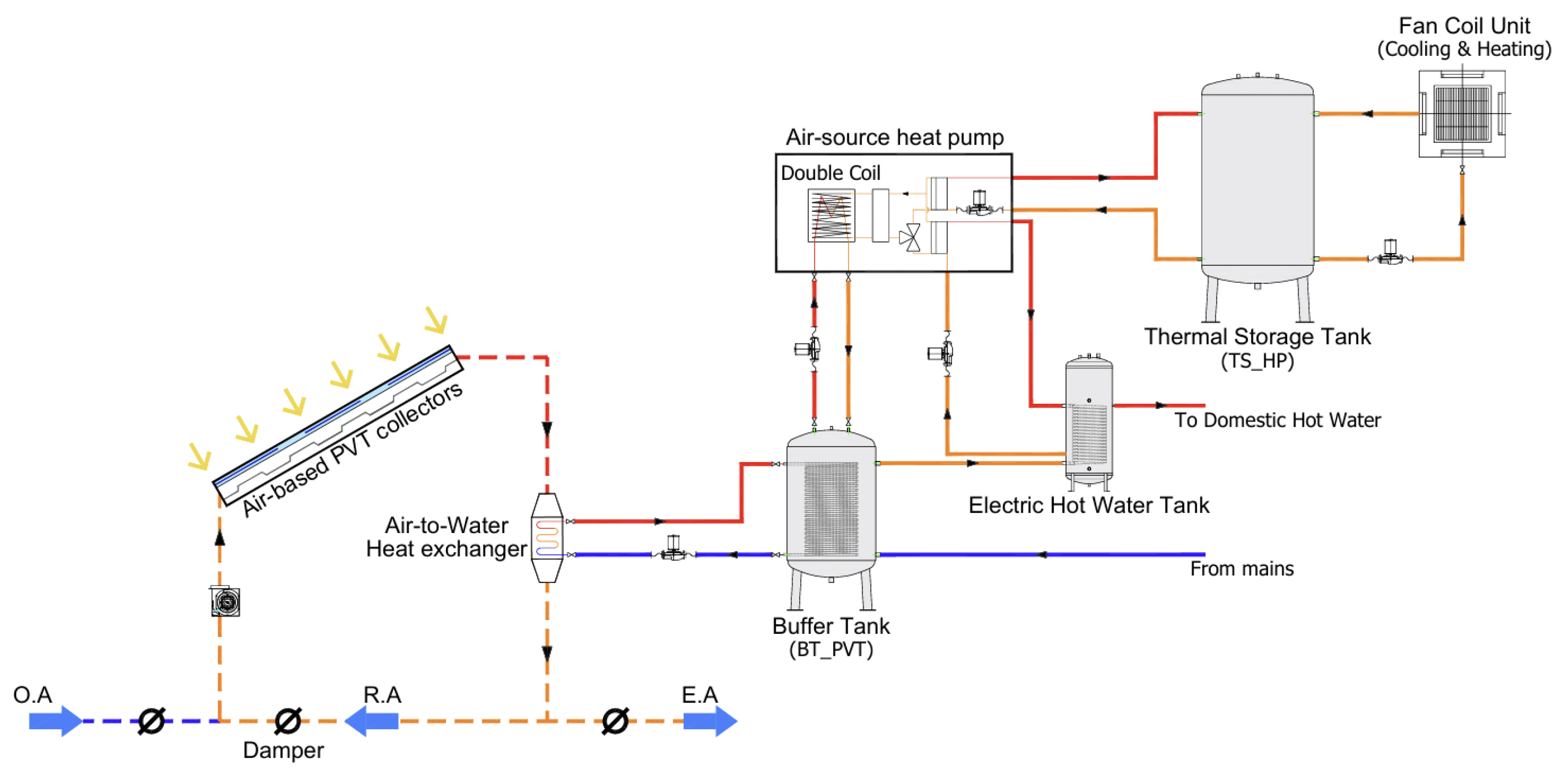
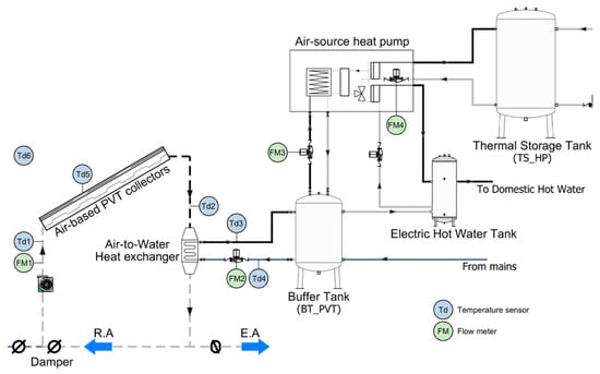
The air-based PVT system was integrated with an a custom-made air-source heat pump (ASHP) system capable of providing space heating, cooling, and domestic hot water (DHW) for the building. Figure 5 illustrates the schematic configuration of the integrated PVT–heat pump system. The installed system consisted of an air-source heat pump unit, a thermal storage tank for space heating and cooling (TS_HP), a buffer tank for PVT energy storage (BT_PVT), a domestic hot water (DHW) tank, and fan coil units (FCUs) connected via circulation pumps and piping. The ASHP was connected to the thermal storage tank (TS_HP) and operated to produce chilled water in summer and hot water in winter, depending on the temperature setpoint of the storage tank. The stored hot or chilled water was circulated to the FCUs, which supplied conditioned air to the school cafeteria through convective heat exchange for space heating or cooling. In addition, the ASHP was connected to the DHW tank to supply hot water at a preset temperature for domestic use within the building.
Figure 5.
Schematic diagram of the air-based PVT–assisted heat pump system. The arrows indicate the airflow paths and the circulation directions of the heat transfer fluid. OA, RA, and EA denote outdoor air, return air, and exhaust air, respectively. The dashed lines represent the airflow ducts, while the solid lines represent the piping network. The red solid lines indicate the heat transfer fluid piping, the orange solid lines represent the return piping from each component, and the blue solid lines indicate the supply and return water piping.
Low-grade thermal energy recovered from the air-based PVT system was stored in the buffer tank (BT_PVT) for preheating the heat pump heat source. The preheated air generated by the PVT collector was directed to an air-to-water heat exchanger, where heat was transferred to the working fluid circulating in the buffer tank. The heated water in the buffer tank was subsequently circulated through a double-coil heat exchanger installed at the rear side of the ASHP, where the outdoor air enters the unit. During winter operation, the incoming cold air for the ASHP evaporator passed over the double-coil heat exchanger and was preheated through heat exchange with the warm water stored in the buffer tank, thereby improving the heat pump operating conditions.
Based on the measured operating conditions of the ASHP described above, the coefficient of performance (COP) was defined to quantitatively evaluate the heating performance of the system. The COP was calculated as the ratio of the useful thermal energy delivered to the thermal storage tank (TS_HP) to the corresponding electrical energy consumption of the heat pump, as expressed in Equation (1).
where QHP is the useful thermal energy delivered to the thermal storage tank (kWh), and WHP is the electrical energy consumption of the heat pump (kWh).
As the air temperature increased while passing through the double-coil heat exchanger, the evaporating temperature of the refrigerant rose, thereby reducing the compressor power demand and improving the heating coefficient of performance (COP) of the system. During summer and intermediate seasons, when space heating was not required, the hot water stored in the buffer tank was utilized as a thermal source for domestic hot water (DHW) production by being connected to the DHW tank. This system configuration enabled the effective use of PVT-derived thermal energy not only for space heating during winter operation but also for year-round domestic hot water supply, thereby enhancing the overall energy efficiency of the integrated system.
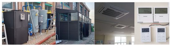
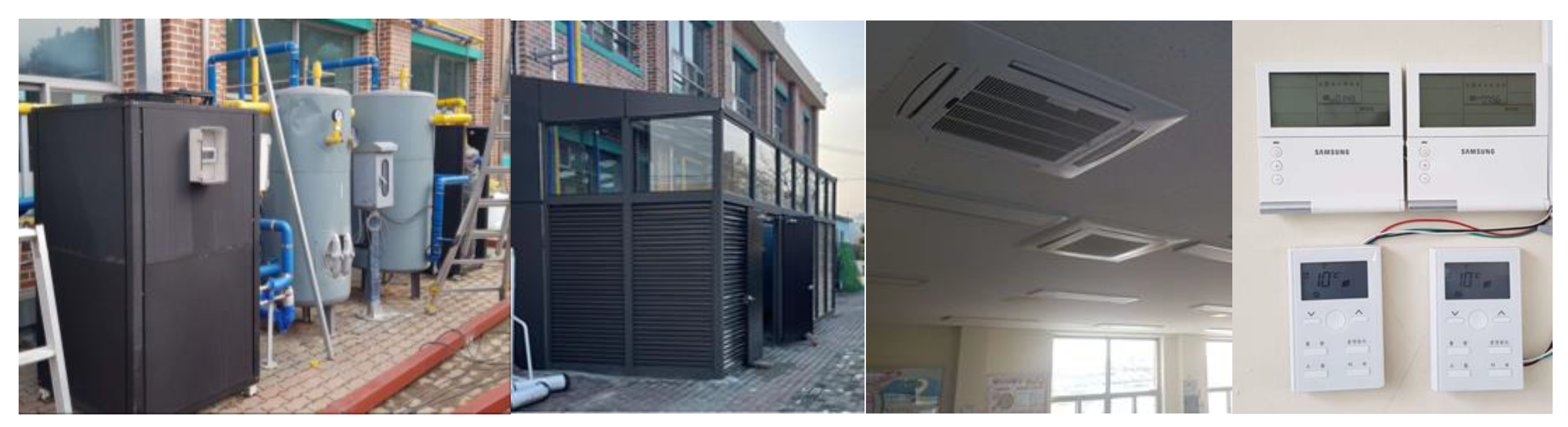
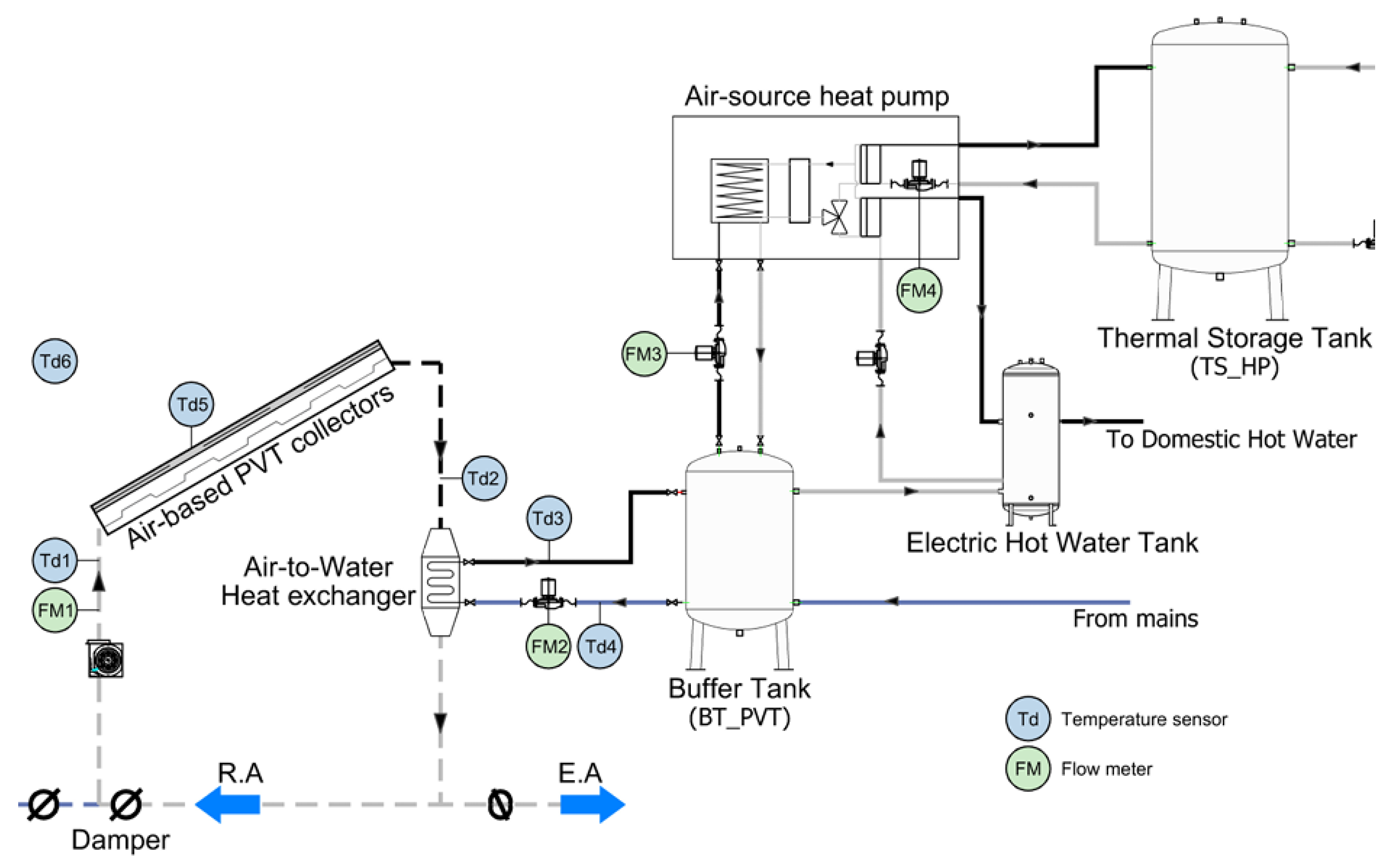
Figure 6 presents photographs of the installed air-source heat pump system and the fan coil units. The main system components were arranged sequentially as the air-source heat pump, the thermal storage tank for space heating and cooling (TS_HP), the buffer tank for PVT-derived thermal energy storage (BT_PVT), and the domestic hot water (DHW) tank. Two fan coil units (FCUs) were installed on the ceiling of the cafeteria and connected to the thermal storage tank (TS_HP) to supply space heating and cooling. Table 2 summarizes the specifications of the main system components excluding the PVT collector, including the heat pump, thermal storage tanks, buffer tank, pumps, and fan coil units. Figure 7 shows the measurement and instrumentation diagram, indicating the locations of all temperature sensors, flow meters, and electrical power meters used in the experimental system. Table 3 summarizes the specifications of the measurement instruments used for the experimental evaluation of the integrated air-based PVT–heat pump system. The electrical consumption of the heat pump and auxiliary components was measured using building-installed electricity meters.
Figure 6.
Photograph of the installed air-source heat pump, thermal storage tank (TS_HP), buffer tank for PVT energy storage (BT_PVT), fan coil (indoor) units, and associated control devices.
Table 2.
Summarizes the specifications of the integrated PVT–heat pump system components (excluding the PVT collector).
Figure 7.
Measurement and instrumentation diagram of the PVT-assisted heat pump system.
Table 3.
Measurement equipment and sensors used in this study.
The parameters and abbreviations used in this study are summarized in Table 4.
Table 4.
Parameters and abbreviations used in this study.
3. Results and Discussion
3.1. Thermal and Electrical Performance of the Air-Based PVT System
To evaluate the performance of the integrated air-based PVT and air-source heat pump (ASHP) system, measured data collected over a one-month period in March 2024 were analyzed. Due to the functional characteristics of the building, the facility was unoccupied during the winter vacation period, and the heat pump system was therefore not operated during that time. Accordingly, data obtained after school operations resumed in March were selected for analysis. This period was considered representative of the actual heating operation conditions of the cafeteria heat pump system, while also providing relatively stable solar irradiance conditions.
During the analysis period, the average plane-of-array solar irradiance was approximately 600 W/m2, with a maximum irradiance reaching 1000 W/m2. Under these conditions, the PVT collector exhibited an average electrical power output of 1.96 kW and an average thermal power output of 2.2 kW. The maximum electrical and thermal power outputs were observed at around 13:00, coinciding with peak solar irradiance, reaching 3.3 kW and 3.8 kW, respectively.
The thermal efficiency (ηth) and electrical efficiency (ηel) were calculated using Equations (2) and (3):
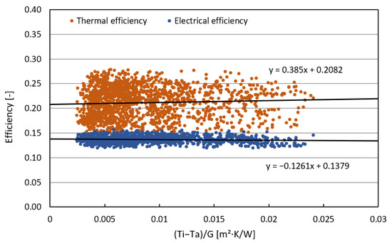
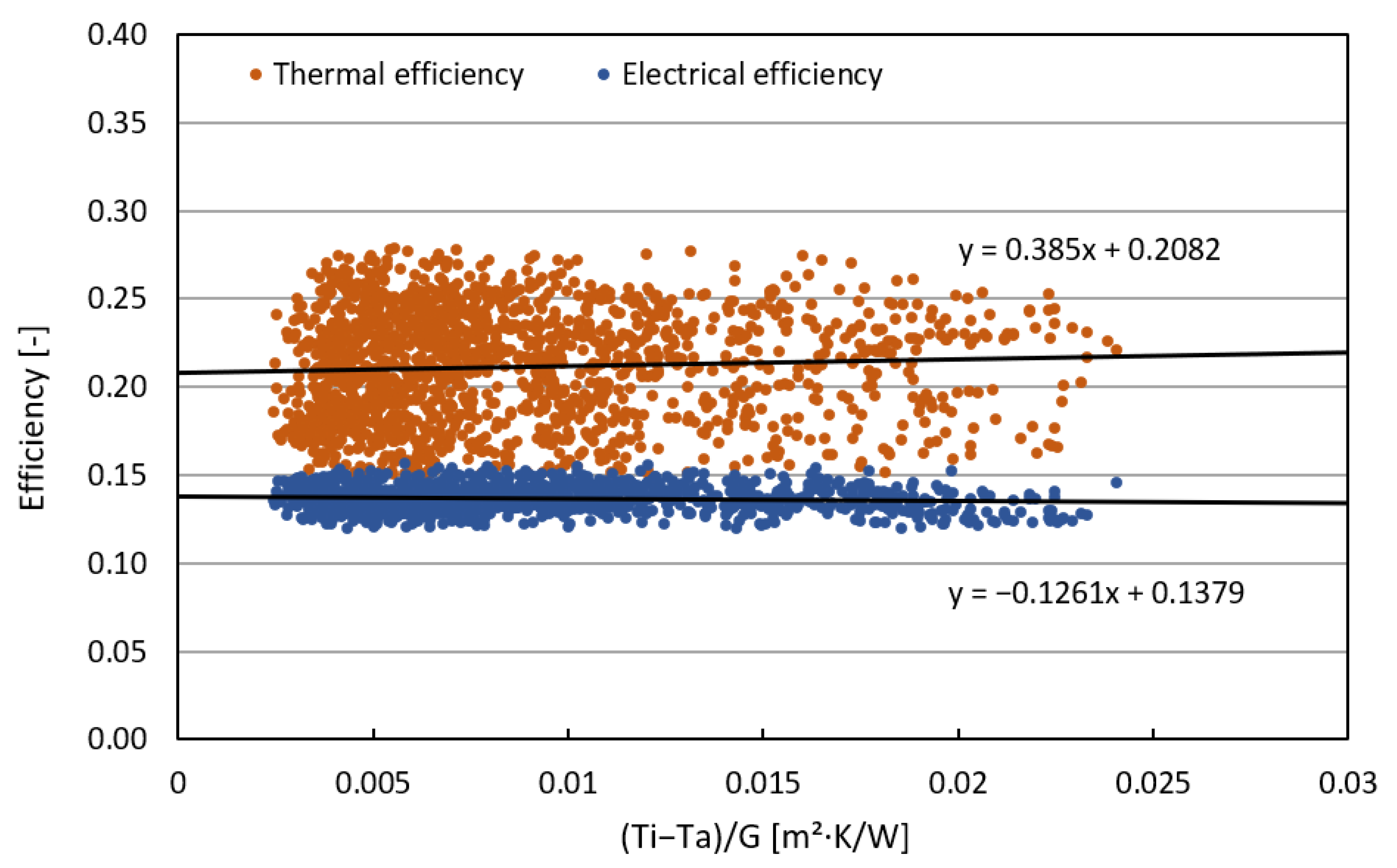
Figure 8 illustrates the thermal and electrical efficiencies of the air-based PVT system as a function of the non-dimensional parameter (Ti − Ta)/G, based on measurement data sampled at a 5-min time step and filtered to include only periods with plane-of-array irradiance exceeding 200 W/m2. The two efficiencies exhibit distinct magnitudes and trends, reflecting the different governing mechanisms of thermal collection and photovoltaic power conversion. The thermal efficiency is mainly distributed in the range of 0.18–0.28, and its regression relationship, ηth = 0.385(Ti − Ta)/G + 0.2082, shows a positive slope. This trend suggests that the thermal efficiency tends to increase gradually with increasing values of the normalized temperature difference under the tested operating conditions. The relatively wide scatter of the thermal efficiency data can be attributed to the sensitivity of thermal performance to variations in airflow conditions and instantaneous fluctuations in solar irradiance.
Figure 8.
Thermal and electrical efficiency of air-based PVT system.
Unlike conventional liquid-based solar thermal collectors, the air-based PVT system investigated in this study operates under forced convection conditions. In such systems, thermal efficiency is influenced more strongly by airflow rate and solar irradiance than by heat-loss-dominated temperature differences. Consequently, the normalized temperature difference (Ti − Ta)/G, defined using the inlet air temperature, can exhibit a positive correlation with thermal efficiency under the examined operating conditions.
In contrast, the electrical efficiency remains within a narrow range of 0.13–0.15. Its regression expression, ηel = −0.1261(Ti − Ta)/G + 0.1379, exhibits a slight negative slope, indicating that the influence of temperature rise on electrical efficiency is limited under the tested operating conditions. The small variation and tight clustering of the electrical efficiency data suggest that PV performance is primarily governed by incident irradiance and cell temperature, while being relatively insensitive to the air-side temperature difference represented by (Ti − Ta)/G. In general, the electrical efficiency of photovoltaic modules tends to decrease with increasing cell temperature. However, the air-based PVT collector investigated in this study maintained a nearly constant electrical efficiency throughout the analysis period. This behavior can be attributed to the forced air circulation within the collector, which effectively removes heat from the rear surface of the photovoltaic modules, thereby suppressing overheating and mitigating temperature-induced degradation in electrical efficiency.
Overall, the results demonstrate that the thermal and electrical performances of the air-based PVT collector exhibit different levels of sensitivity to environmental and operating conditions. Thermal efficiency responds more noticeably to variations in the normalized temperature difference, whereas electrical efficiency remains comparatively stable with only a weak dependence on (Ti − Ta)/G.
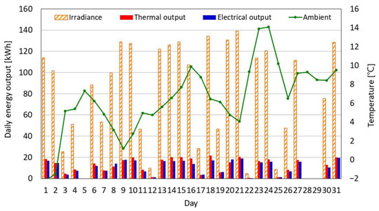
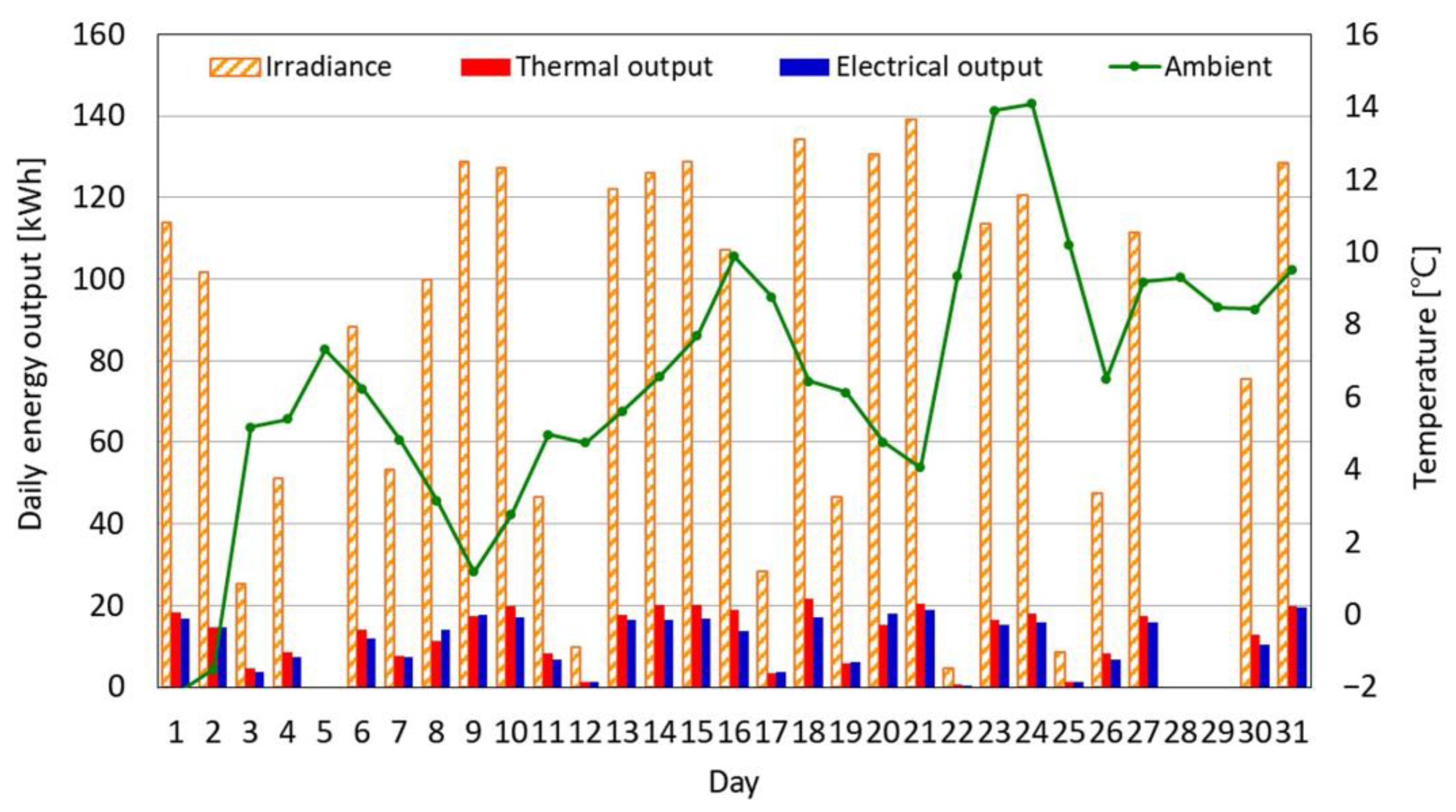
Figure 9 presents the daily variations in total solar energy incident on the PVT collector, thermal output, electrical output, and ambient temperature over the observation period. In this study, daily solar energy refers to the total solar energy incident on the entire PVT col-lector surface, expressed in kWh, rather than an area-normalized value. The results show that both thermal and electrical outputs generally follow the variation in solar availability. Days with higher incident solar energy exhibit higher thermal and electrical generation, whereas days with reduced solar input correspond to lower outputs. Throughout the month, the thermal output remains notably higher than the electrical output, with thermal energy typically ranging from approximately 8 to 14 kWh/day, while electrical energy remains within 2 to 4 kWh/day. This consistent magnitude difference indicates that the air-based PVT system produces substantially greater thermal energy than electrical energy under real outdoor operating conditions. In addition, the thermal output exhibits relatively stable day-to-day behavior, whereas the electrical output shows slightly larger fluctuations, reflecting its stronger sensitivity to variations in solar conditions. Ambient temperature shows a gradual rise and fall over the month; however, no clear direct correlation between ambient temperature and either thermal or electrical output is evident from the dataset. Overall, Figure 9 demonstrates that solar input is the primary factor governing both thermal and electrical production of the air-based PVT system, while thermal output remains the dominant and more stable component of the system’s overall energy yield.
Figure 9.
Daily total solar energy incident on the PVT collector surface, thermal output, electrical output, and ambient temperature of the air-based PVT system.
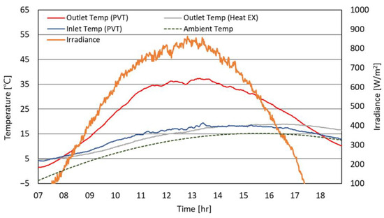
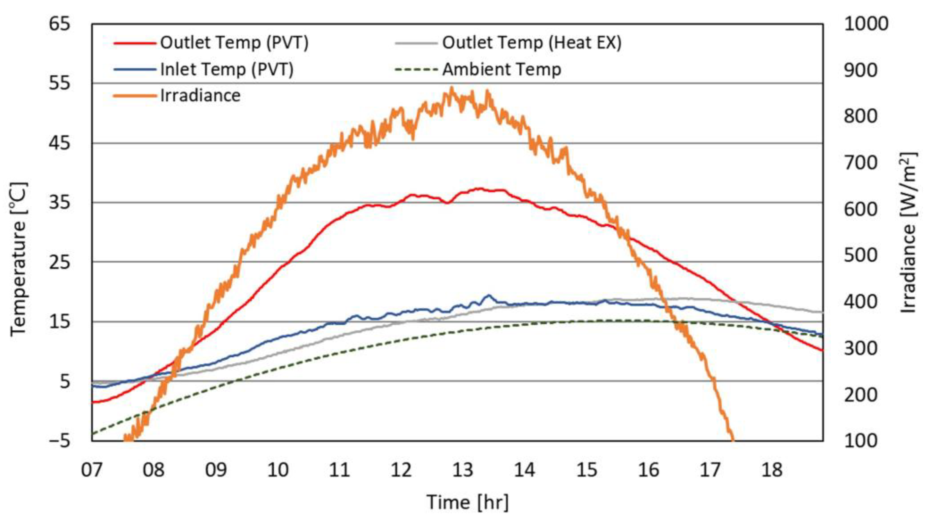
Figure 10 presents the temperature characteristics of the air-based PVT system, including the inlet and outlet temperatures of the PVT collector, the outlet temperature of the air-to-water heat exchanger, the ambient temperature, and the corresponding solar irradiance. The inlet air temperature of the PVT collector begins at approximately 5 °C in the early morning and gradually increases to about 19 °C near midday as solar irradiance rises. The PVT outlet temperature shows a more pronounced temperature rise, increasing from roughly 8 °C in the morning to a peak of approximately 37 °C around noon. This results in a maximum temperature gain across the collector of nearly 20 °C, with a typical daytime temperature difference of 8–20 °C between the inlet and outlet air streams.
Figure 10.
Time-series temperature profiles of the air-based PVT system with irradiance. (This figure was newly replotted based on the original experimental dataset, with reconfigured legends, axis ranges and scaling, and color schemes.)
After passing through the air-to-water heat exchanger, the outlet air temperature decreases significantly compared with the PVT outlet temperature, typically remaining around 18–22 °C at midday. This reduction confirms effective heat transfer from the PVT-heated air to the water in the storage tank. The heat-exchanger outlet temperature also remains consistently higher than the ambient temperature throughout the daytime period, demonstrating that the PVT system maintains the ability to supply elevated-temperature air even under fluctuating environmental conditions.
Overall, the results indicate that the air-based PVT system effectively captures solar energy, provides a substantial temperature rise across the collector, and delivers usable thermal energy to the heat exchanger for subsequent heat storage and heat-pump assistance.
3.2. Heating Performance of the PVT-Assisted Air-Source Heat Pump
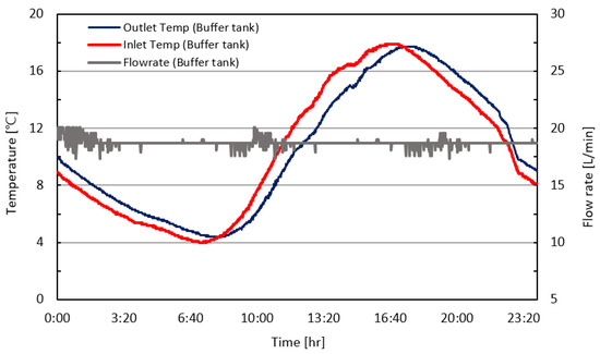
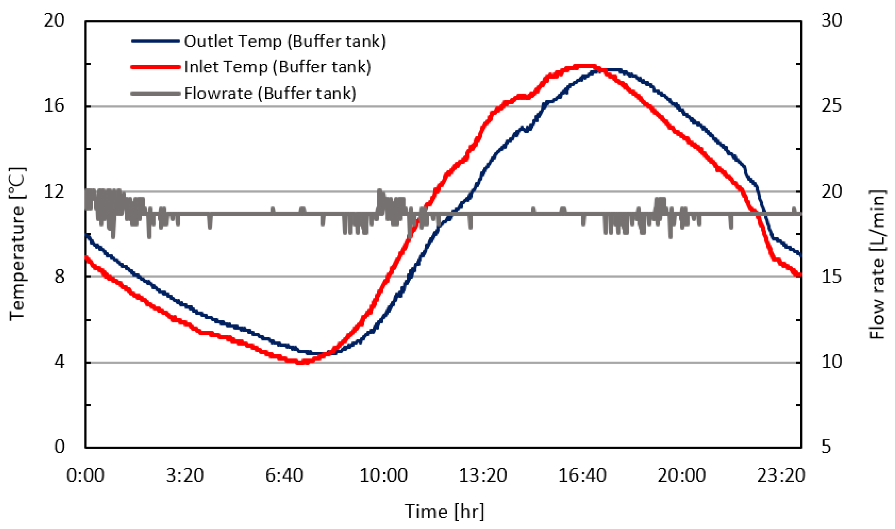
Figure 11 presents the thermal and operational characteristics of the buffer tank over a 24-h period, showing the water temperature entering the tank (inlet), the water temperature leaving the tank (outlet), and the corresponding circulation flow rate during thermal charging from the air-based PVT system. The primary purpose of presenting the flow-rate profile is not to emphasize its absolute magnitude, but to confirm continuous circulation operation during heat storage and discharge periods. The relatively stable flow rate observed throughout the day indicates steady system operation, while short-term fluctuations around midnight, late morning, and evening are attributed to pump on/off control in response to the availability of thermal energy recovered from the PVT collector. These transient variations reflect normal operational control behavior rather than system instability.
Figure 11.
Time-series temperature and flow rate characteristics of the buffer tank. (This figure was newly replotted based on the original experimental dataset, with reconfigured legends, axis ranges and scaling, and color schemes.)
Both inlet and outlet temperatures decrease during the early morning, reaching minimum values of approximately 4–5 °C around 07:00. As thermal energy from the air-based PVT system begins to be supplied, the inlet temperature to the buffer tank increases sharply, rising from about 6 °C in the morning to a peak of approximately 18 °C in the late afternoon. The outlet temperature from the buffer tank follows a similar diurnal trend, increasing steadily and reaching a maximum of around 18 °C.
During the primary heat storage period (approximately 09:00–18:00), the inlet temperature to the buffer tank remains consistently 2 °C higher than the outlet temperature from the buffer tank, indicating continuous net heat accumulation within the tank. After sunset, both temperatures gradually decline as solar heat input decreases and thermal losses dominate. The flow rate remains relatively stable throughout the day, confirming consistent circulation during both charging and discharging cycles.
Overall, the temperature profiles demonstrate that the buffer tank effectively stores thermal energy supplied by the air-based PVT system, exhibiting clear diurnal heating and cooling behavior aligned with solar availability.
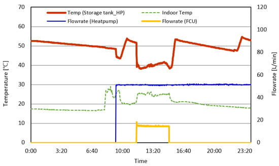
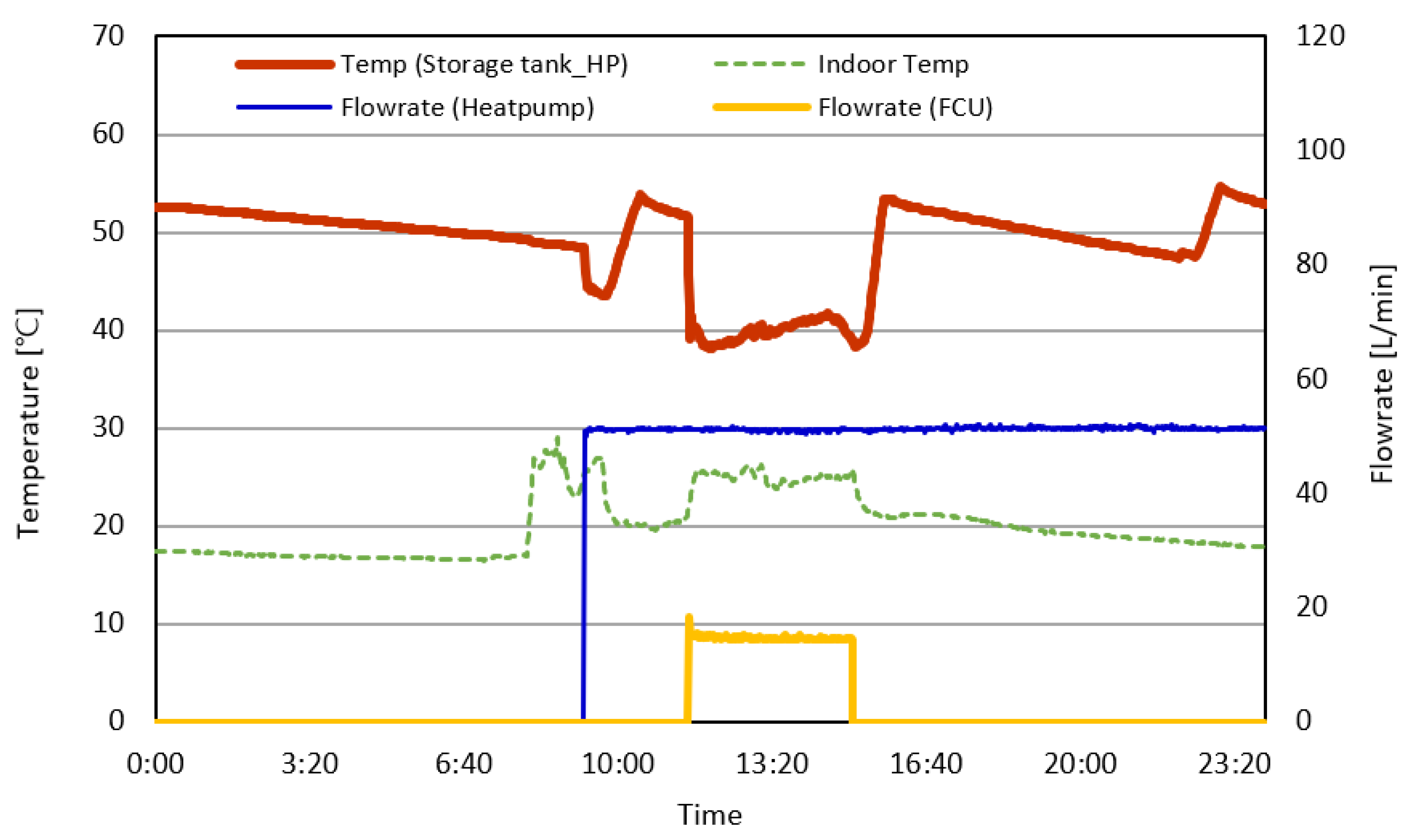
Figure 12 illustrates the temperature and flow-rate characteristics of the air-source heat pump system during heating operation, including the storage-tank temperature of the heat pump, indoor temperature, and the circulation flow rates of both the heat pump loop and the fan coil units (FCUs). The heating setpoint temperature of the heat pump was maintained at 50 °C. When the storage-tank temperature dropped below this threshold, the heat pump automatically activated to raise the water temperature back to the setpoint. This control behavior is clearly observed around 10:00 and 23:00, where decreases in storage-tank temperature triggered reheating cycles.
Figure 12.
Time-series variations in storage tank temperature, heat pump and FCU flow rates, and indoor temperature. (This figure was newly replotted based on the original experimental dataset, with reconfigured legends, axis ranges and scaling, and color schemes.)
The FCUs were activated at approximately 11:30, circulating hot water from the storage tank to the FCU coils for space heating in the cafeteria. During this period, the storage-tank temperature gradually decreased as stored heat was consumed to meet indoor heating demand. Concurrently, the indoor air temperature increased, reflecting effective heat transfer from the FCU coils to the occupied space. The flow rates of both the heat pump loop and the FCU loop remained stable throughout their respective operating periods, indicating consistent circulation and reliable system control.
The repeated rise–fall pattern of the storage-tank temperature corresponds well with heating demand and heat pump operation cycles, demonstrating that the integrated air-based PVT and ASHP system effectively managed thermal storage and heat delivery while maintaining indoor comfort. These results confirm that the system operated in a stable and responsive manner under actual building heating conditions.
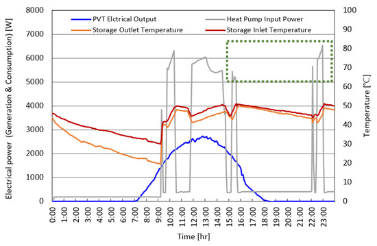
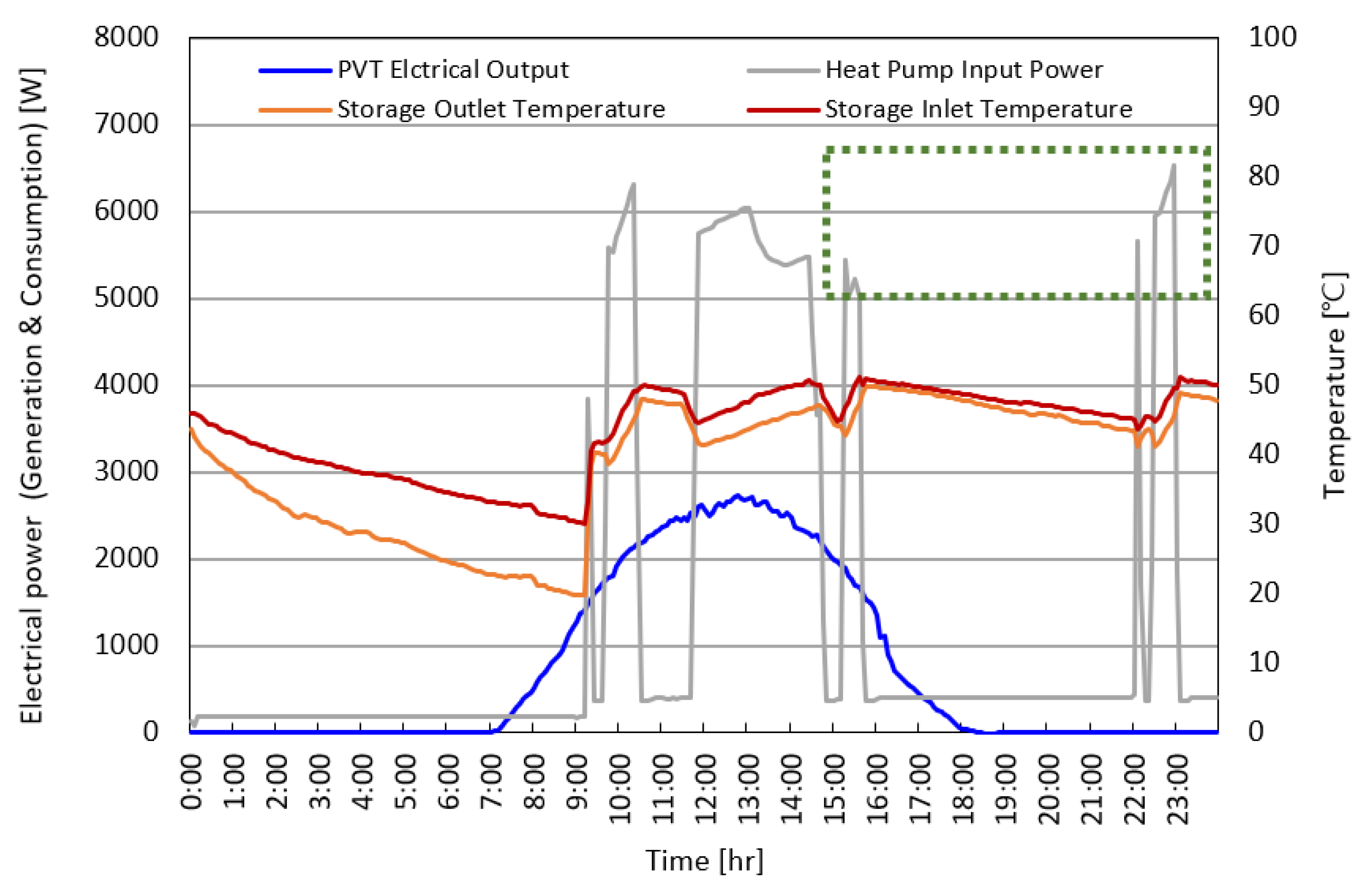
Figure 13 presents time-series data obtained from continuous field measurements. The data represent instantaneous operating conditions of the system rather than results from repeated experiments conducted under identical conditions. The purpose of this figure is to illustrate the temporal relationship among the electrical output of the air-based PVT system, the buffer tank temperatures, and the power consumption of the heat pump.
Figure 13.
Time-series variations in PVT electrical output, electrical power demand of heat pump and storage tank inlet/outlet temperatures. The green dashed box indicates the time period of heat pump operation when the storage tank temperature was maintained around the heating setpoint, used to analyze the effect of PVT-assisted preheating on electrical power consumption. (This figure was newly replotted based on the original experimental dataset, with reconfigured legends, axis ranges and scaling, and color schemes.)
The heat pump was automatically activated when the storage-tank temperature fell below the heating setpoint of 50 °C, resulting in distinct operation cycles at approximately 10:00, 11:30, and 23:00. During each activation, the electrical power demand of the heat pump increased sharply to around 6 kW, with noticeable variations depending on the time of day. The electrical power demand of the heat pump was approximately 5.5–6.5 kW during morning and nighttime operation (around 10:00 and 23:00), whereas the power demand decreased to about 5.0–6.0 kW during daytime operation (11:40–15:40). This reduction is attributed to the preheating effect provided by the air-based PVT system.
The COP analysis further confirmed this trend. When the heat pump was activated during the period from 15:20 to 15:40, after the storage-tank temperature dropped below 50 °C, the COP reached 2.81, and the corresponding electrical energy consumption was approximately 2.26 kWh. In contrast, during the nighttime operation from 22:30 to 22:55, when no solar-assisted preheating was available, the COP decreased to 2.24 while the energy consumption increased to 3.36 kWh. This result indicates that, under the measured operating conditions, the electricity consumption of the heat pump during daytime operation with PVT preheating was approximately 33% lower than that during nighttime operation without solar assistance. This observed difference reflects the system-level impact of utilizing PVT-derived thermal energy as a supplementary heat source during heating operation.
In this study, the preheating effect of the air-based PVT system was evaluated at the system level based on measured operating performance of the heat pump. Rather than directly quantifying local temperature gradients or heat transfer at the evaporator surface, the influence of PVT-derived thermal energy was assessed through changes in overall heating performance under different operating conditions.
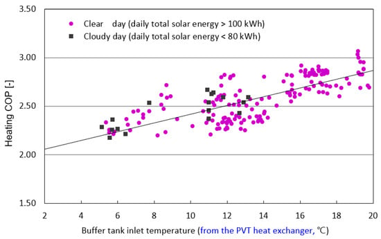
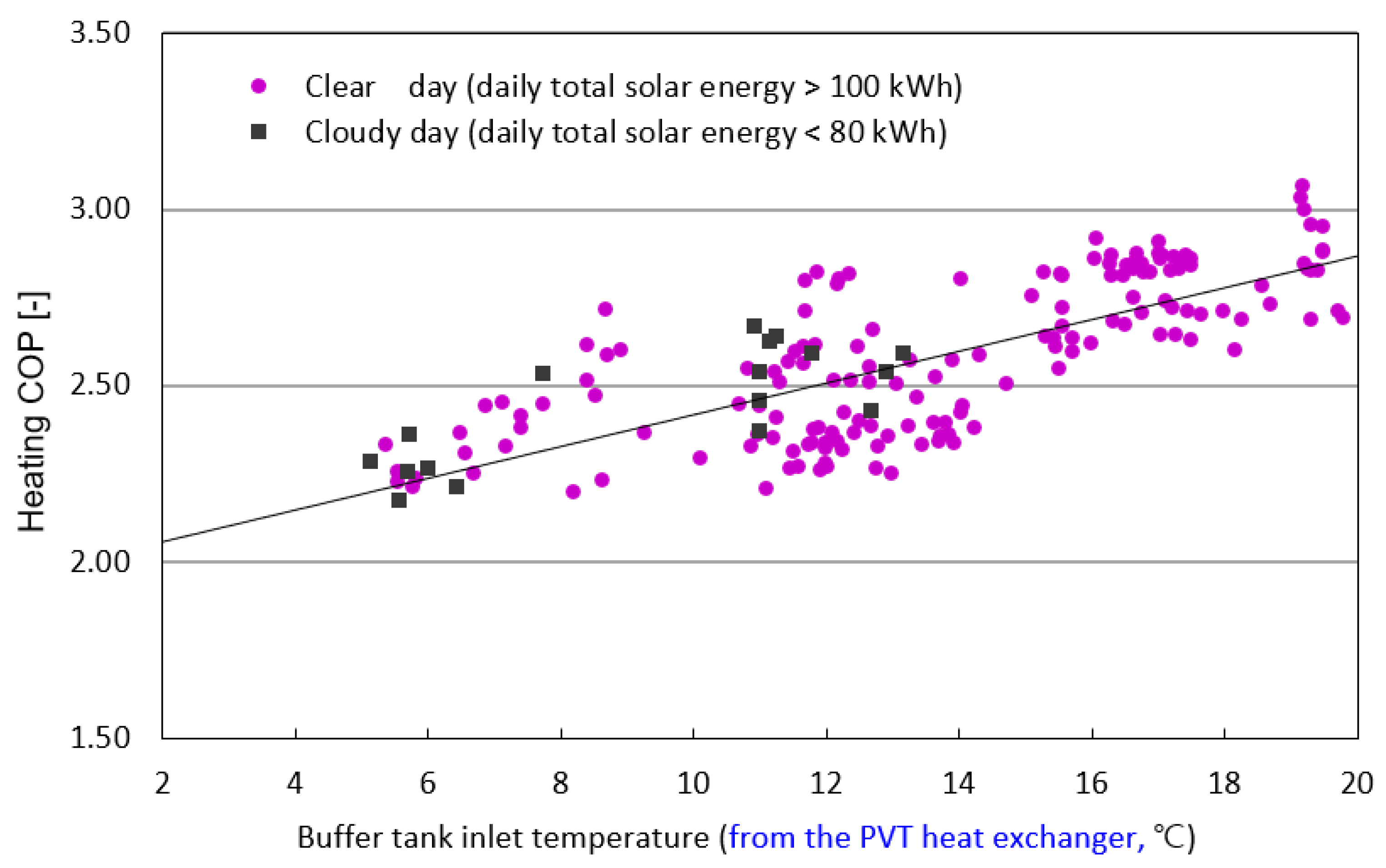
Figure 14 shows the relationship between the heating COP of the air-source heat pump and the buffer-tank inlet temperature under different solar irradiation conditions. The heating COP exhibits a clear positive correlation with the inlet temperature of the buffer tank. As the inlet temperature increases from approximately 4 °C to 19 °C, the heating COP rises from around 2.0 to values exceeding 3.0. This trend indicates that higher inlet temperatures reduce the temperature lift required by the heat pump, thereby improving heating performance.
Figure 14.
Variation in heating COP with buffer tank inlet temperature under clear and cloudy conditions. (Clear days correspond to cases with a daily total solar energy incident on the entire PVT collector area exceeding 100 kWh, while cloudy days correspond to cases with values below 80 kWh. The daily total solar energy represents the total solar energy incident on the entire PVT collector area, obtained by integrating the plane-of-array irradiance over time and multiplying by the total PVT area.). The grey line represents the linear regression trend illustrating the relationship between the buffer tank inlet temperature and the heating COP.
When comparing operating conditions, data points collected on clear days (daily total solar irradiation incident on the PVT collector surface > 100 kWh) generally show higher COP values than those recorded on cloudy days (daily total solar irradiation < 80 kWh). The scatter distribution indicates that, within the same inlet temperature range, COP values under clear-day conditions tend to exceed those under cloudy conditions by approximately 0.1–0.3. This difference can be attributed to the additional preheating effect provided by the PVT system during clear conditions, which elevates the buffer-tank inlet temperature and enhances heat pump efficiency.
Overall, the results demonstrate that the buffer-tank inlet temperature is a strong indicator of heat pump performance, and that solar-assisted operation under clear-sky conditions contributes to higher heating COP by reducing the effective thermal load on the heat pump.
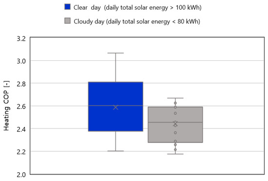
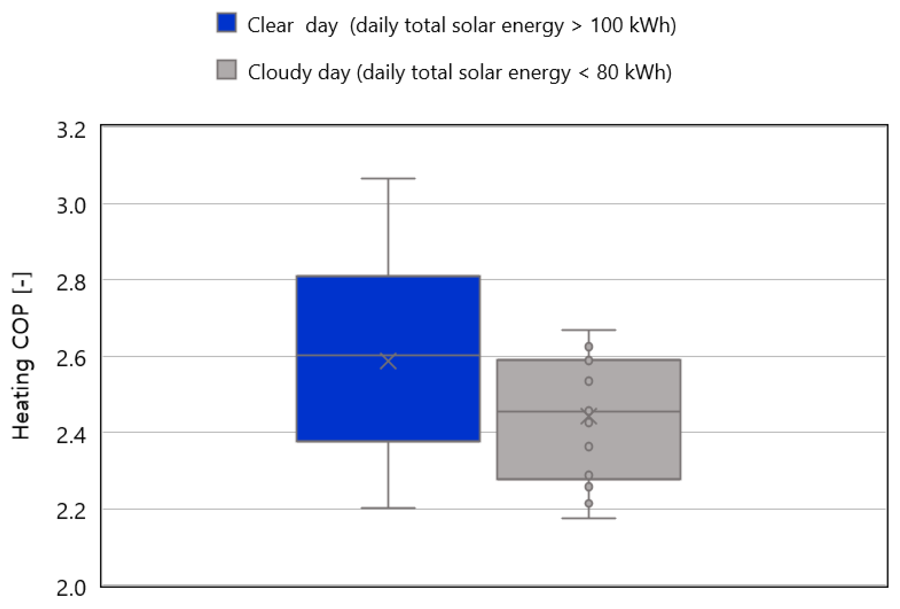
Figure 15 compares the heating COP of the heat pump under clear (daily total solar energy incident on the PVT collector > 100 kWh) and cloudy (daily total solar energy < 80 kWh) conditions. The differences in COP observed between the two cases primarily reflect the operational contribution of the PVT system, rather than differences in solar availability alone. On clear days, the PVT system generated sufficient thermal energy to provide effective preheating to the heat pump evaporator, whereas on cloudy days the PVT contribution was negligible and the heat pump operated without effective solar assistance. According to the box plot results, the COP under clear-day conditions exhibits higher values and a wider distribution, with median values ranging from approximately 2.65 to 2.75 and maximum values exceeding 3.0. In contrast, the COP under cloudy conditions remains lower, with a median of approximately 2.45 and no values exceeding 2.7. These results indicate that enhancements in heating COP are closely associated with the level of thermal assistance provided by the PVT system, suggesting that the presence or absence of effective PVT operation plays a key role in determining heat pump performance.
Figure 15.
Distribution of heating COP under clear-day and cloudy-day conditions, classified based on daily total solar energy incident on the PVT collector. The box plots represent the distribution of heating COP values. The boxes indicate the interquartile range, the horizontal lines inside the boxes denote the median values, the crosses represent the mean values, the whiskers indicate the minimum and maximum values, and the dots represent individual data points.
It should be noted that the preheating effect discussed in Figure 14 is evaluated at the system level based on changes in overall heat pump performance. The temperature measurement points employed in this study were not intended to capture detailed local temperature gradients on the evaporator surface or inside the PVT collector. Accordingly, the observed COP variation reflects an operational outcome of PVT-assisted heating rather than a direct quantification of local heat transfer mechanisms.
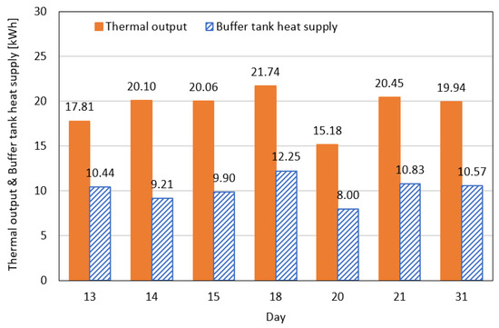
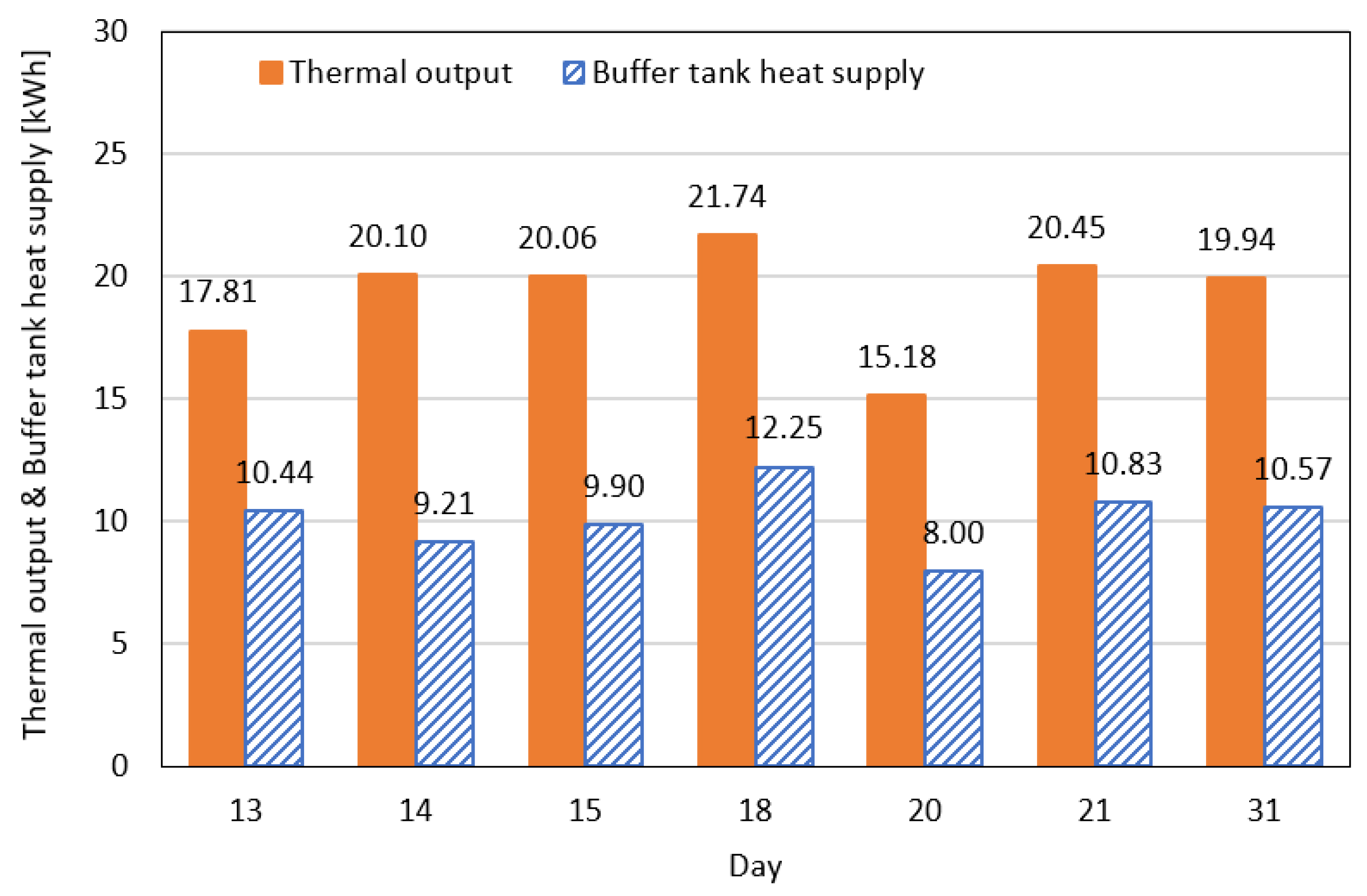
Figure 16 compares the daily thermal output of the air-based PVT system and the amount of heat delivered to the buffer tank through the heat exchanger on clear days with daily total solar energy exceeding 100 kWh. The PVT output remains relatively stable, ranging from 17.81 to 21.74 kWh, indicating limited day-to-day variation under high solar energy conditions. The heat supplied to the buffer tank ranges from 8.00 to 12.25 kWh, corresponding to approximately 45–60% of the thermal energy recovered from the air-based PVT collector. This proportion represents the measured heat transfer efficiency of the air-to-water heat exchanger under the given operating conditions and falls within the typical performance range reported for conventional air-to-water heat exchangers. These results indicate that the air-based PVT system maintains stable thermal production under clear-sky conditions and is capable of transferring and storing a substantial fraction of the generated thermal energy in the buffer tank. This suggests that the integrated PVT–buffer tank configuration can provide sufficient thermal capacity to function as a reliable auxiliary heat source for building heating applications.
Figure 16.
Comparison of PVT output and buffer tank heat supply on clear days.
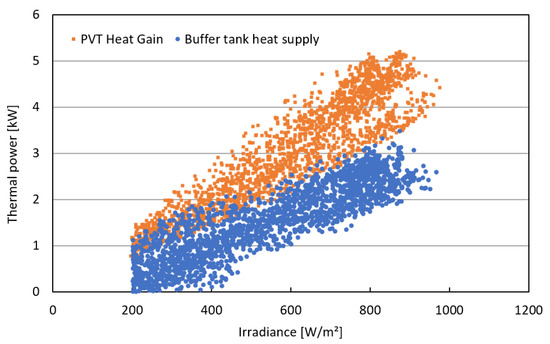
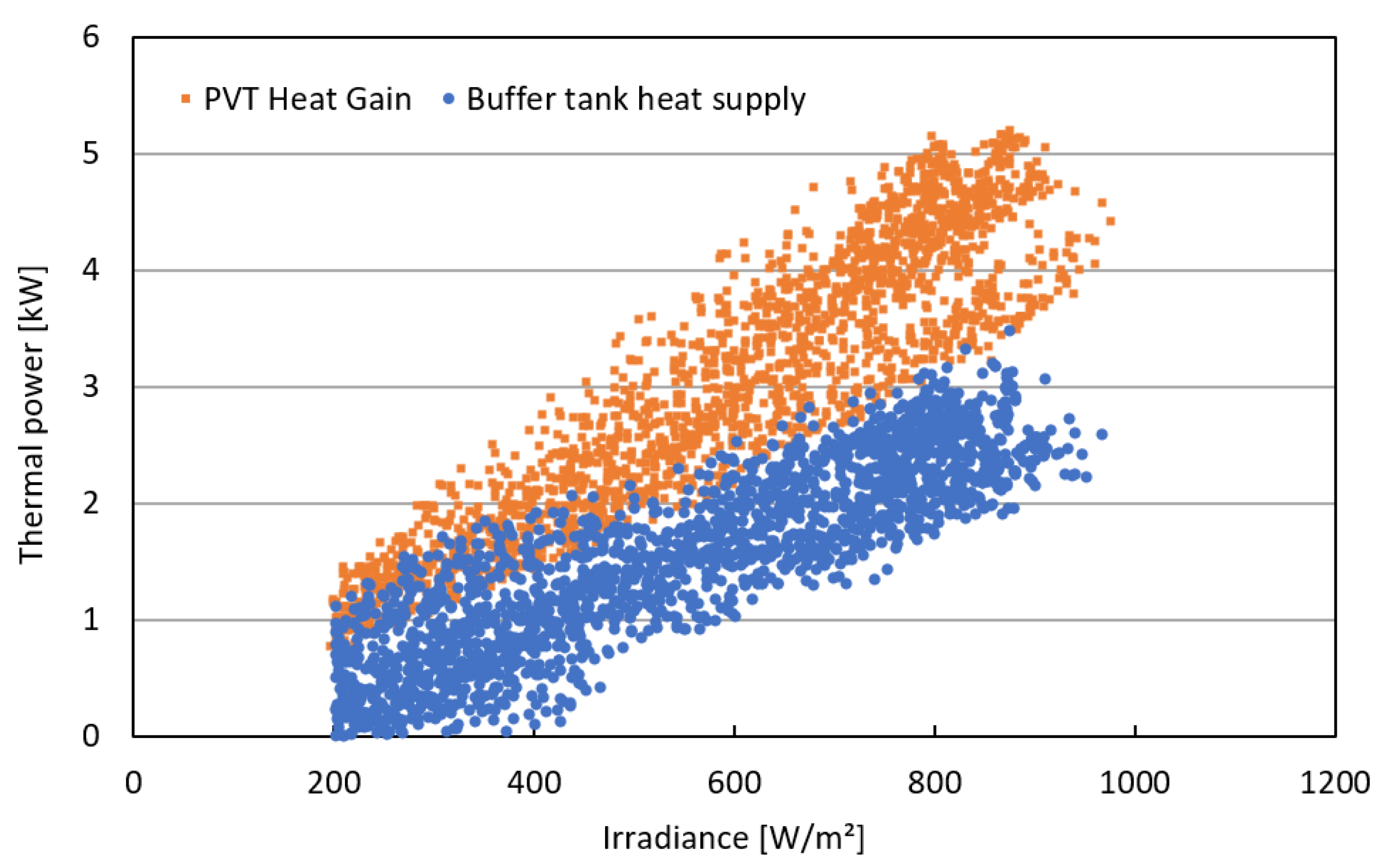
Figure 17 illustrates the instantaneous thermal power produced by the PVT collector and the thermal power delivered to the buffer tank as a function of solar irradiance, together with the corresponding heat transfer efficiency. Both thermal power outputs increase approximately linearly with irradiance, confirming that solar input is the dominant factor governing the thermal performance of the system. Across all operating conditions, the PVT heat gain remained higher than the heat delivered to the buffer tank, which can be attributed to heat losses during heat exchange and the thermal inertia of the storage tank.
Figure 17.
PVT heat gain and buffer tank heat supply under varying irradiance.
Under high irradiance conditions (600–900 W/m2), the instantaneous PVT heat gain reached approximately 4–5 kW, while the corresponding thermal power supplied to the buffer tank ranged from 2 to 3.5 kW. Even under low irradiance levels (200–400 W/m2), both quantities exhibited consistent increasing trends. The similar slopes of the two distributions indicate a proportional response of both PVT production and tank-supplied heat to changes in irradiance, demonstrating predictable heat-supply behavior under varying solar conditions.
The instantaneous heat transfer efficiency was calculated as
where Qtank and QPVT are the instantaneous thermal powers (kW) delivered to the buffer tank and produced by the PVT collector, respectively, and t denotes time.
The calculated heat transfer efficiency ηHT exhibited a gradual increase with rising solar irradiance. Specifically, the efficiency ranged from approximately 50–55% under low-irradiance conditions, 55–60% under medium irradiance, and reached 60–65% under high irradiance. This trend indicates that a greater proportion of the useful thermal energy generated by the PVT module is transferred to the buffer tank as irradiance increases. In other words, the heat exchange performance becomes more pronounced under high-irradiance conditions, resulting in a higher amount of recoverable thermal energy being stored in the buffer tank
Figure 16 and Figure 17 present complementary analyses of the heat transfer performance from the PVT collector to the buffer tank. While Figure 16 evaluates the daily energy-based heat transfer efficiency, Figure 17 provides insight into the instantaneous thermal power behavior and the time-dependent variation in heat transfer efficiency under dynamic operating conditions.
To further clarify the differentiated value of the proposed system, it is useful to compare the air-based PVT-assisted air-source heat pump configuration with other solar-assisted heating technologies. Conventional solar collector-assisted heat pump systems typically employ liquid-based solar thermal collectors, which can provide stable thermal input but often involve additional complexity related to antifreeze requirements, leakage risks, and maintenance of hydraulic components. Moreover, their integration with building HVAC systems may be constrained by the need for separate thermal circuits and storage systems. In contrast, direct photovoltaic-driven air-source heat pump systems primarily utilize on-site electricity generation to offset compressor power consumption. While this approach can reduce grid electricity demand, it does not directly utilize low-grade thermal energy and therefore cannot contribute to evaporator-side preheating or mitigation of performance degradation under low ambient temperature conditions.
The air-based PVT-assisted system investigated in this study combines electrical generation and thermal recovery using a single building-integrated component and employs air as the heat transfer medium, enabling simpler integration with building ventilation and HVAC systems. Rather than aiming to outperform other solar-assisted technologies in terms of peak efficiency, the proposed configuration demonstrates a practical operational pathway in which recovered thermal energy is utilized as a supplementary heat source under real building operating conditions. This distinction highlights the potential role of air-based PVT-assisted heat pump systems as a flexible and application-oriented solution for solar-assisted building heating, particularly where simplicity, integration, and operational robustness are prioritized.
4. Conclusions
This study presented a demonstration-scale performance evaluation of an air-based photovoltaic/thermal (PVT) system integrated with an air-source heat pump (ASHP) under real building operating conditions. Field measurements confirmed that the integrated system was capable of simultaneously providing electrical generation and thermal energy recovery in a stable and consistent manner during the heating operation period, demonstrating the practical feasibility of air-based PVT–ASHP integration in real buildings.
A substantial portion of the thermal energy recovered from the air-based PVT collector was effectively delivered to the buffer tank through the air-to-water heat exchanger under actual operating conditions. This result demonstrates the feasibility of utilizing PVT-derived thermal energy for system-level integration with heat pump operation, rather than indicating technological advancement of the heat exchanger itself.
The results further show that the PVT-assisted preheating effect was associated with improved heating performance of the air-source heat pump during daytime operation. Higher coefficients of performance were observed under solar-assisted conditions compared to nighttime operation without preheating. The distinction in COP distributions between clear and cloudy conditions suggests that the observed performance trend was primarily influenced by the utilization of PVT-derived thermal energy as a supplementary heat source, rather than by solar irradiance alone.
Overall, this study differs from previous work largely limited to laboratory-scale experiments, numerical simulations, or liquid-based PVT systems by providing demonstration-scale experimental evidence of an air-based photovoltaic thermal (PVT)–air-source heat pump (ASHP) integrated system implemented in a real building. The results help bridge the gap between component-level investigations and practical building-scale ap-plications, highlighting the practical applicability of air-based PVT-assisted heat pump systems for solar-assisted building heating.
However, the findings presented in this study should be interpreted as demonstration-scale results obtained under specific heating-period operating conditions, rather than as statistically generalized or representative annual performance metrics. In particular, the preheating effect identified in this study should be understood as a system-level operational outcome observed under real building conditions, rather than as a detailed characterization of local heat transfer mechanisms within individual PVT or heat pump com-ponents.
It should be noted that this investigation was conducted under realistic building operation, where repeated experiments under identical conditions are inherently difficult; accordingly, the findings should be interpreted as system-level performance trends rather than statistically generalized results, and future work will focus on extended long-term monitoring covering extreme winter conditions, transitional seasons, and summer domestic hot water operation, together with the installation of additional temperature sensors within the PVT collector and on the heat pump evaporator surface to improve reproducibility and enable more detailed analysis of thermal mechanisms under diverse operating conditions.
Author Contributions
Conceptualization, J.-H.K. and J.-T.K.; methodology, J.-H.K., H.-Y.K. and S.-M.K.; validation, J.-H.K.; formal analysis, J.-H.K., H.-Y.K. and S.-M.K.; investigation, J.-H.K. and S.-M.K.; resources, J.-H.K. and S.-M.K.; data curation, J.-H.K. and H.-Y.K.; writing—original draft preparation, J.-H.K.; writing—review and editing, J.-H.K. and J.-T.K.; visualization, J.-H.K. and H.-Y.K.; supervision, J.-T.K.; project administration, J.-H.K. and J.-T.K.; funding acquisition, J.-T.K. All authors have read and agreed to the published version of the manuscript.
Funding
This work was supported by the Korea Institute of Energy Technology Evaluation and Planning (KETEP) through the Ministry of Trade, Industry and Energy (MOTIE), Republic of Korea (RS-2023-00266248, RS-2024-00394769).
Data Availability Statement
The original contributions presented in the study are included in the article, and further inquiries can be directed to the corresponding author.
Conflicts of Interest
The authors declare no conflicts of interest.
References
- Intergovernmental Panel on Climate Change (IPCC). Global Warming of 1.5 °C: IPCC Special Report on Impacts of Global Warming of 1.5 °C Above Pre-Industrial Levels in Context of Strengthening Response to Climate Change, Sustainable Development, and Efforts to Eradicate Poverty; Cambridge University Press: Cambridge, UK, 2022. [Google Scholar] [CrossRef] [Scilit]
- 2050 Carbon Neutrality Committee. 2050 Carbon Neutrality Scenario. 2050 Carbon Neutrality Committee Secretariat. 2021. Available online: https://www.2050cnc.go.kr/base/board/read?boardManagementNo=4&boardNo=101&page=1&searchCategory=&searchType=&searchWord=&menuLevel=2&menuNo=15 (accessed on 15 December 2025).
- U.S. Department of Energy. Inflation Reduction Act of 2022: Clean Energy and Climate Provisions; U.S. Department of Energy: Washington, DC, USA, 2022.
- European Commission. Fit for 55′: Delivering the EU’s 2030 Climate Target on the Way to Climate Neutrality; European Commission: Brussels, Belgium, 2021. [Google Scholar]
- European Commission. REPowerEU Plan; European Commission: Brussels, Belgium, 2022. [Google Scholar]
- Ministry of Trade, Industry and Energy. Renewable Energy 3020 Implementation Plan (Draft); Announcement No. 2017-12; Ministry of Trade, Industry and Energy: Sejong, Republic of Korea, 2017; Available online: https://www.motie.go.kr/kor/article/ATCL3f49a5a8c/159996/view# (accessed on 15 December 2025).
- A Joint Session of Relevant Ministries. 2030 NDC Upward Plan; Announcement No. 2021-10; Joint Session of Relevant Ministries: Seoul, Republic of Korea, 2021; Available online: http://webarchives.pa.go.kr/19th/www.2050cnc.go.kr/base/board/read?boardManagementNo=4&boardNo=84&searchCategory=&page=1&searchType=&searchWord=&menuLevel=2&menuNo=15 (accessed on 15 December 2025).
- Lee, G.B.; Kang, J.Y. The Impact of Renewable Energy Sources on Greenhouse Gas Emissions Reduction -Focusing on Solar and Wind Energy. New Reneable Energy 2025, 21, 60–70. [Google Scholar] [CrossRef] [Scilit]
- Tripanagnostopoulos, Y.; Nousia, T.; Souliotis, M.; Yianoulis, P. Hybrid photovoltaic/thermal solar systems. Sol. Energy 2002, 72, 217–234. [Google Scholar] [CrossRef] [Scilit]
- Zondag, H.A. Flat-plate PV–thermal collectors and systems: A review. Renew. Sustain. Energy Rev. 2008, 12, 891–959. [Google Scholar] [CrossRef] [Scilit]
- Kasaeian, A.; Khanjari, Y.; Golzari, S.; Mahian, O.; Wongwises, S. Performance evaluation of air-based photovoltaic thermal systems: A review. Renew. Sustain. Energy Rev. 2018, 81, 2270–2289. [Google Scholar] [CrossRef] [Scilit]
- International Energy Agency (IEA). Net Zero by 2050: A Roadmap for the Global Energy Sector; IEA Publications: Paris, France, 2021. [Google Scholar]
- Staffell, I.; Brett, D.; Brandon, N.; Hawkes, A. A review of domestic heat pumps. Energy Environ. Sci. 2012, 5, 9291–9306. [Google Scholar] [CrossRef] [Scilit]
- Kim, S.M.; Kim, J.H.; Kim, J.T. Experimental study on the thermal and electrical characteristics of an air-based photovoltaic thermal collector. Energies 2019, 12, 2661. [Google Scholar] [CrossRef] [Scilit]
- Othman, M.Y.H.; Yatim, B.; Sopian, K.; Bakar, M.N.A. Performance analysis of a double-pass photovoltaic/thermal (PV/T) solar collector with CPC. Renew. Energy 2005, 30, 2005–2017. [Google Scholar] [CrossRef] [Scilit]
- Sopian, K.; Liu, H.T.; Kakac, S.; Veziroglu, T.N. Performance of a double-pass photovoltaic thermal solar collector suitable for solar drying systems. Energy Convers. Manag. 2000, 41, 353–365. [Google Scholar] [CrossRef] [Scilit]
- Chow, T.T.; Ji, J.; He, W. Photovoltaic–thermal collector system for domestic application. J. Sol. Energy Eng. 2009, 131, 041007. [Google Scholar] [CrossRef] [Scilit]
- He, W.; Chow, T.T.; Ji, J.; Lu, J.; Pei, G.; Chan, L.S. Hybrid photovoltaic and thermal solar-collector designed for natural circulation of water. Appl. Energy 2006, 83, 199–210. [Google Scholar] [CrossRef] [Scilit]
- Jin, G.; Ibrahim, A.; Gomes, R.; Liu, X. Thermal performance optimization of an air-based photovoltaic/thermal system. Energy Convers. Manag. 2017, 136, 156–167. [Google Scholar] [CrossRef] [Scilit]
- Kim, J.H.; Kim, S.M.; Kim, J.T. Experimental Performance of an Advanced Air-Type Photovoltaic/Thermal (PVT) Collector with Direct Expansion Air Handling Unit (AHU). Sustainability 2021, 13, 888. [Google Scholar]
- Joo, H.J.; An, Y.S.; Lee, K.H. Development and Performance Analysis of an Air Source Heat Pump Outdoor Unit Heating System with Photovoltaic Thermal Modules. J. Korean Sol. Energy Soc. 2023, 43, 163–180. [Google Scholar] [CrossRef] [Scilit]
- Hailu, G.; Dash, P.; Fung, A.S. Performance evaluation of an air source heat pump coupled with a building-integrated photovoltaic/thermal (BIPV/T) system under cold climatic conditions. Energy Procedia 2015, 78, 1913–1918. [Google Scholar] [CrossRef] [Scilit]
- Kamel, R.; Ekrami, N.; Dash, P.; Fung, A.; Hailu, G. BIPV/T+ ASHP: Technologies for NZEBs. Energy Procedia 2015, 78, 424–429. [Google Scholar] [CrossRef] [Scilit]

Disclaimer/Publisher’s Note: The statements, opinions and data contained in all publications are solely those of the individual author(s) and contributor(s) and not of MDPI and/or the editor(s). MDPI and/or the editor(s) disclaim responsibility for any injury to people or property resulting from any ideas, methods, instructions or products referred to in the content. |
© 2026 by the authors. Licensee MDPI, Basel, Switzerland. This article is an open access article distributed under the terms and conditions of the Creative Commons Attribution (CC BY) license.