


Abstract
The widespread integration of inverter-based distributed generators (IIDGs) severely limits the adaptability of conventional three-step overcurrent protection in distribution networks (DNs). To address weak rural infrastructure and incomplete post-fault data, this paper proposes a dynamic adaptive current protection strategy for active distribution networks (ADNs) against two-phase short-circuit faults (TPSCFs), using local sequence components. First, we derive analytical expressions for positive/negative-sequence current/voltage at feeder outlet protection devices during TPSCFs, analyzing how the IIDG fault output affects these components. Based on this, an adaptive scheme is developed using only local measurements, with feeder head voltage/current sequence components as criteria. Leveraging line impedance and topology, the scheme ensures selective, accurate fault section identification under incomplete measurements, requiring only feeder head sequence data. A high-IIDG-penetration DN model is built in PSCAD/EMTDC, and TPSCFs under various conditions are simulated. Results show the scheme provides rapid, reliable full-line protection for TPSCFs in IIDG-penetrated ADNs, enhancing protection effectiveness.
1. Introduction
Under the “dual carbon” goals, the penetration of IIDGs, primarily photovoltaics, has been steadily rising in DNs in recent years [1,2,3]. The extensive integration of IIDGs transforms DNs from originally single-source, purely radial passive networks with unidirectional power flow into ADNs containing multiple power sources, characterized by bidirectional power flow and complex fault characteristics. When short-circuit faults occur in an ADN, the fault current exhibits bidirectional flow characteristics, and its distribution pattern changes, thereby altering the fundamental requirements for traditional three-step current protection [4]. Conventional three-step current protection methods based on fault-phase current magnitude characteristics now face risks such as diminished sensitivity, failure to operate, or maloperation. This situation urgently calls for overcoming technical bottlenecks in fault location and isolation in ADNs.
In recent years, extensive research has been conducted on communication-based protection schemes for ADNs. Ref. [5] proposes a 5G-enabled protection scheme to achieve precise fault location and isolation in distribution networks with high distributed generation penetration, addressing the inadequacy of conventional overcurrent protection. Ref. [6] proposed a pilot protection scheme via high-frequency fault analysis using equivalent high-frequency impedance modeling and fault-induced high-frequency superimposed network analysis, significantly enhancing fault resistance and noise immunity in high-PV-penetration distribution networks. Ref. [7] introduces a two-stage, distributed multi-agent protection strategy for active distribution networks. The scheme combines local fault detection with agent-coordinated operating time optimization, effectively addressing challenges from bidirectional power flow and inverter-based resources. Ref. [8] constructed a protection criterion based on the inter-line harmonic current difference by establishing harmonic layers and active harmonic injection, achieving channel-less primary protection and demonstrating adaptability to various complex operating conditions. Refs. [9,10] proposed an adaptive differential protection scheme based on current amplitude and phase compensation by introducing an adaptive compensation coefficient, effectively enhancing the detection sensitivity for high-impedance internal faults. Building on this, to reduce differential protection requirements for data synchronization and communication devices, Ref. [11] proposed a quasi-power differential protection scheme, effectively mitigating the impact of unmeasured load branches on protection sensitivity in multi-branch active distribution networks. Ref. [12] proposes principles and criteria for impedance differential protection by utilizing the distinct differences between differential impedance and restraint impedance during normal operation, external faults, and internal faults. This approach allows rapid fault identification while effectively addressing complex conditions, including transition resistance, CT saturation, and asynchronous data. Such communication-based protection methods can incorporate multi-source information for auxiliary judgment, typically offering absolute selectivity and excellent sensitivity.
However, in scenarios where communication is unavailable, the aforementioned methods are rendered ineffective. In particular, rural or remote DNs often lack sufficient infrastructure, with communication equipment either absent or unreliable, making it impossible to fully acquire or transmit line electrical quantities. This leads to incomplete post-fault electrical information and renders communication-based line protection methods inapplicable. Among protection strategies relying solely on local information, adaptive current protection demonstrates distinct advantages. It can perform adaptive setting adjustments based on real-time fault conditions, effectively addressing multiple uncertainties such as fluctuations in IIDG output, changes in system operating modes, and variations in fault location. Consequently, research on adaptive protection methods for ADNs under incomplete information conditions becomes imperative.
Currently, significant research efforts have been devoted to adaptive current protection techniques that rely on locally measurable data. To address the issues of fault current nonlinearity and dynamic topological variations caused by high-penetration IIDG integration, Ref. [13] proposed a local-information-based adaptive current protection scheme by introducing the positive-sequence voltage-current relationship for online fault distance calculation and real-time protection setting adjustment. Ref. [14] develops an adaptive current protection method based on correlation impedance matrices, which incorporates dynamic setting adjustment and data correction mechanisms. Refs. [15,16] focus on maloperation issues in ADN protection resulting from IIDG integration, proposing improved protection schemes that optimize protection settings via dynamic adjustment of reliability-related parameters, thereby effectively enhancing the adaptability of traditional protection to IIDG integration scenarios. Ref. [17] proposes an adaptive restraining current correction method using feeder-end current amplitude ratios, specifically designed to address time synchronization errors during high-impedance faults.
Protection methods that fully leverage information from feeder head-end installations can rapidly and effectively safeguard lines based on a non-communication principle. The approach for calculating protection settings depends on the specific arrangements of protection relays and circuit breakers, requiring tailored strategies for each configuration. A common framework in the literature assumes a multi-section feeder architecture, with each segment protected by a dedicated relay and circuit breaker, and with IIDGs connected at the feeder busbars. This configuration, however, does not align with the actual conditions of most ADN feeders, highlighting the urgent need for research into adaptive current protection schemes suitable for networks where protection devices and circuit breakers are installed only at feeder head-ends and branch line heads. Consequently, a key challenge in designing such schemes is how to more effectively utilize limited measurement information from protection devices. The selection of adaptive current protection criteria is fundamentally determined by the fault type. Specifically, these criteria must be tailored to different fault types, as the electrical characteristics and protection setting requirements for TPSCFs differ from those for common single-line-to-ground faults. Considering the practical needs of technology projects and space limitations, this paper focuses on TPSCFs as representative cases. The proposed method is highly scalable and can be extended to other fault types with minor adjustments, and its general applicability will be further demonstrated in subsequent studies. The underlying protection setting principles are universally valid, and the analytical approaches for other fault types follow a similar logic, which will be detailed in future work. This research focuses on long-distance overhead lines serving remote rural areas, which typically use non-effectively grounded neutral systems. For grounding faults, the analysis can employ transient models suitable for high-impedance fault conditions [18].
In response to the aforementioned challenges, this paper proposes an adaptive current protection scheme for ADNs under conditions of incomplete information, based on integrated sequence components and specifically designed for TPSCFs. The scheme makes full use of current and voltage measurements from the feeder outlet protective devices, and incorporates each line segment’s impedance characteristics as well as the fault output characteristics of IIDGs, thereby establishing a protection setting methodology for ADNs with incomplete information. By analyzing the network topology and utilizing the current and voltage sequence components measured at the feeder outlets, the scheme ensures selective and correct operation of protection devices while accurately identifying faulty line sections.
Section 2 analyzes the adaptability of conventional current protection schemes in distribution networks with high IIDG penetration, and introduces the topological configuration of the studied ADN scenario. Section 3 investigates the fault characteristics at different locations along the ADN lines during faults. Section 4 elaborates on the development of an adaptive protection method based on these fault characteristics and establishes the corresponding setting criteria for individual lines. Section 5 presents a PSCAD/EMTDC model of a high-penetration IIDG ADN and conducts numerical verification for faults at various locations.
2. Adaptability Analysis of Traditional Current Protection
2.1. Output Characteristics of IIDG
Many nations have introduced mandates and grid code requirements to facilitate the integration of renewable energy sources into existing power systems.
In China, the national standard GB/T 19964-2024 Technical Requirements for Connecting Photovoltaic Power Stations to Power Systems stipulates that large-scale IIDG grid connections must possess low-voltage ride-through capability [19]. Specifically, during power system faults that cause voltage sags at the photovoltaic station’s connection point, IIDGs are required to remain connected and operate continuously for a defined period, subject to specified voltage dip ranges and time intervals.
The United States first introduced IEEE Standard 1547 in 2009, which originally required IIDGs to rapidly disconnect from the grid during system abnormalities [20]. However, with increasing renewable energy penetration, the 2023 revision now mandates that distributed generation systems have dynamic voltage support capability, requiring them to maintain grid connection for specified durations during voltage sags [21]. In Germany, regulations as early as 2010 required renewable energy power plants (RESPPs) to provide dynamic reactive power support and frequency response, with these provisions later extended to medium-voltage distribution networks [22].
According to surveys of actual IIDG manufacturers, IIDGs must be capable of providing dynamic reactive power support during low-voltage ride-through events, with their reactive current output tracking real-time variations in the grid point voltage. The injected reactive current is generally governed by Equation (1).
where represents the reactive portion of output current. represents voltage at the IIDG grid connection point. represents rated system voltage. represents the rated current of IIDG.
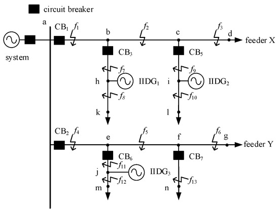
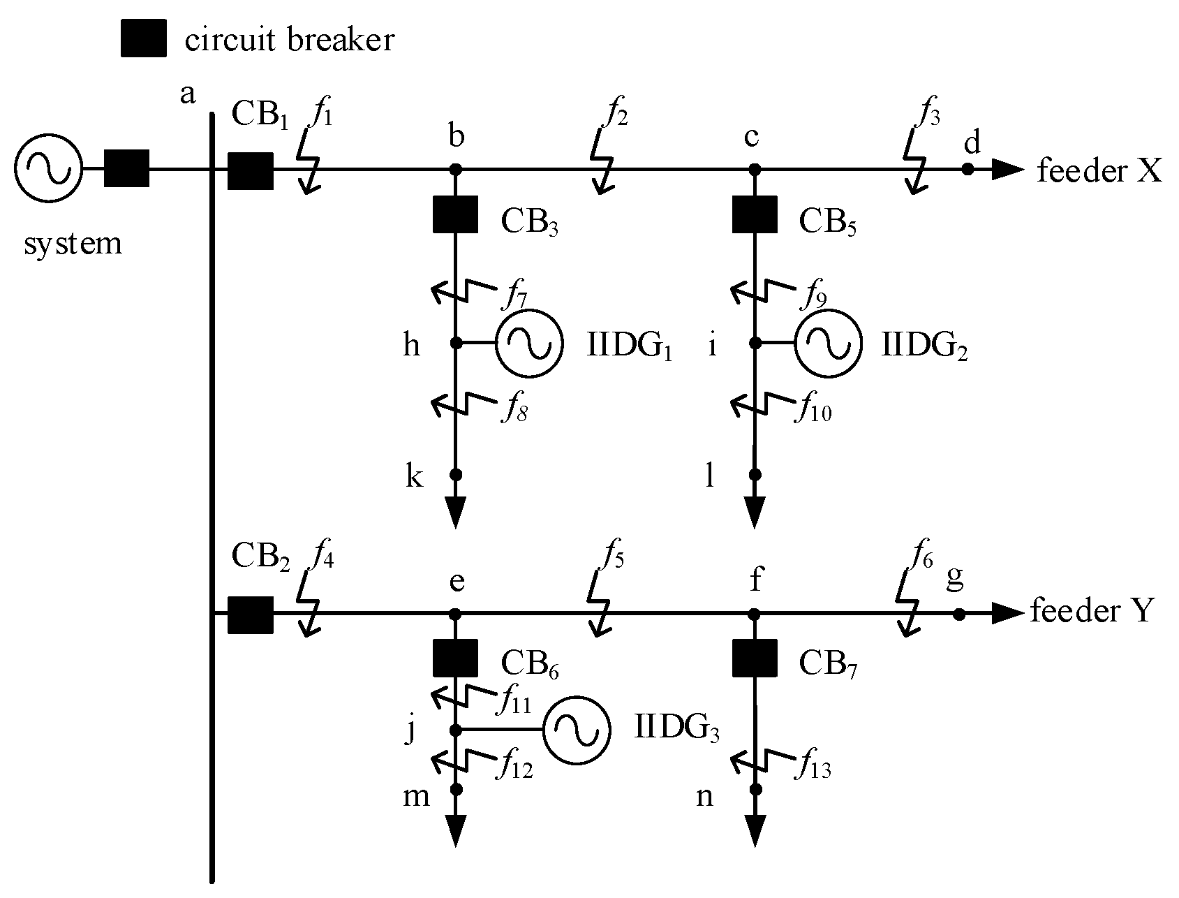
Figure 1 shows the typical ADN topology with multiple IIDGs, in which the protection devices and circuit breakers for the feeder and its lateral branches are installed only at their respective starting points. Additionally, IIDGs are typically installed on the customer side and are therefore connected to the distribution network via branch lines. Applying both traditional three-step current protection and adaptive protection methods to this typical ADN poses significant challenges.
Figure 1.
Typical topology structure and protection configuration diagram of ADN.
2.2. The Performance Degradation of the Traditional Three-Stage Current Protection
The impact of IIDG integration on short-circuit currents in distribution networks primarily involves two aspects: outward fault currents and reverse power flow. When a TPSCF occurs on an upstream line relative to an IIDG, the IIDG becomes isolated from the system. In this scenario, the IIDG integration does not change the short-circuit current level detected by the protection device at the feeder head-end.
For a downstream short-circuit fault, current injection from the IIDG causes a significant voltage rise at its grid connection point. This decreases the short-circuit currents on upstream lines, thereby reducing the sensitivity of both instantaneous and time-delayed overcurrent protection set according to maximum load conditions. In extreme cases, it may even lead to a complete failure of protection across the entire line.
Additionally, during faults on adjacent feeders, reverse currents from IIDGs flow back through their local feeder protection. This can cause maloperation of stage III overcurrent protection, or potentially even stage II or stage I protection [23], which necessitates the installation of directional protection relays to avoid such misoperations.
2.3. Failure of Conventional Adaptive Current Protection to Adapt
Traditional adaptive current instantaneous trip protection dynamically sets its operating value online based on the system’s real-time operating condition and fault type, according to the short-circuit current at the end of the protected line. The current setting value IZDZ is shown in Equation (2).
where represents the system equivalent voltage. represents the system equivalent impedance. represents the impedance of the protected line. represents the reliability coefficient, which can be taken as 1.2 ~ 1.3. The coefficient is defined based on the fault type: it is 1 for three-phase faults and for phase-to-phase faults.
The fault output characteristics of IIDGs, governed by their control strategies, differ markedly from those of traditional synchronous generators and cannot be simply modeled as an ideal voltage source with a series impedance. Unlike in traditional power systems, the conventional rule that a two-phase fault current equals times the three-phase fault current no longer holds for the same location in ADNs. Thus, the fault type coefficient in traditional adaptive current protection becomes inapplicable for IIDG-integrated ADNs. Furthermore, existing adaptive current protection methods are confined to identifying the feeder section between the protection device and the IIDG point of common coupling. These methods do not adequately address the common grid configuration where IIDGs are connected to the main feeder via branch lines. This limitation makes current adaptive protection schemes unsuitable for the representative ADN topology illustrated in Figure 1.
3. Fault Analysis of ADN Under TPSCF
Next, the correlation between sequence currents and voltages measured at feeder head-end protection during TPSCFs at different locations is further analyzed.
The ADN topology shown in Figure 1 is widely adopted in Chinese rural DNs. The system has a reference capacity of 100 MVA, a reference voltage of 10.5 kV, and a system impedance of j 0.27 Ω. Two feeders extend from the busbar, with each feeder being subdivided into three segments by branch lines. In order to comprehensively represent possible IIDG integration configurations, feeder X has IIDGs integrated on both branch lines, and feeder Y has an IIDG integrated on its upstream lateral. CBX denotes line protection devices, while IIDGX represents IIDG, with a capacity set to 2 MW. In addition, the line parameters are set to r1 = 0.27 Ω/km, x1 = 0.346 Ω/km. In feeder X, the lines ab, bc, cd, bh, and ci are all 2 km, and the lines hk and il are all 1 km. In feeder Y, the lines ae, ef, fg, ej, and jm are all 2 km, and the line fn is 4 km. The system configuration includes a load of 2 MVA (power factor 0.85) served by the main feeder and its branches.
To ensure a comprehensive study, various fault locations across all feeders and branch lines within the ADN, shown in Figure 1, are analyzed. Among them, , and represent the output current of three distributed power sources, respectively, represents the internal impedance of the system, and represents the equivalent potential of the system.
3.1. Faults on the Main Line of Feeder X
3.1.1. At f1 on Line ab
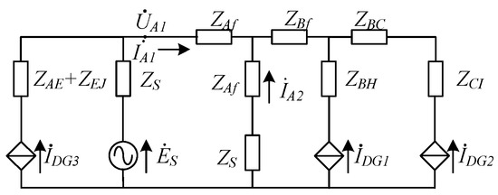
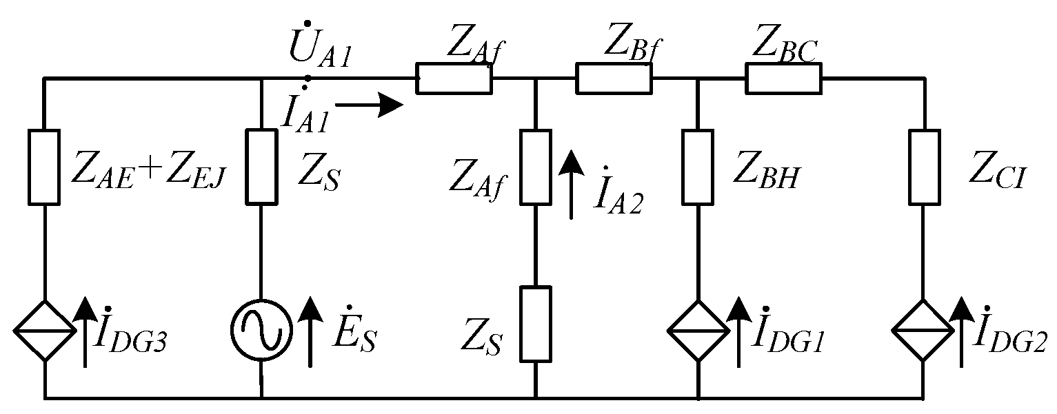
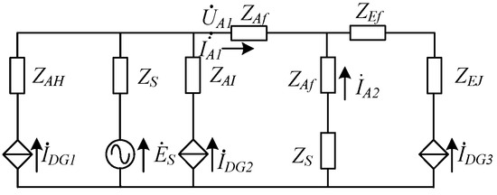
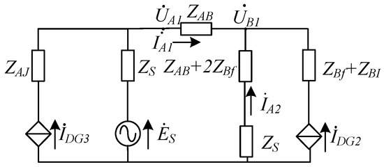
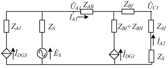
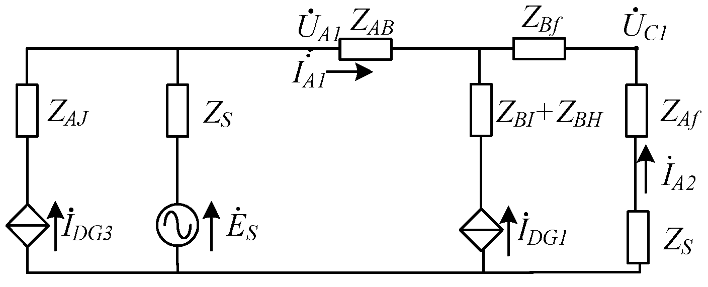
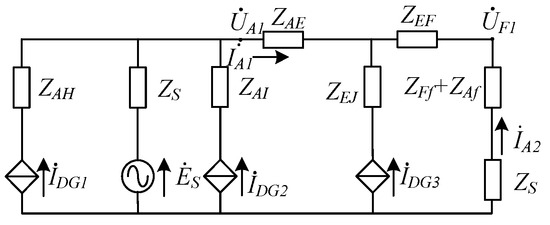
Figure 2 illustrates the composite sequence network of the ADN for a TPSCF occurring at f1. As the targeted supply area is a DN in remote rural regions, both the distributed loads along feeders and terminal concentrated loads are typically small with minimal variation. Consequently, these loads are neglected in the fault characteristic analysis.
Figure 2.
Composite Sequence Network for a TPSCF at f1.
Here, represents the line impedance from protection 1 location a to the fault point, and represents the line impedance from point b (end of line ab) to the fault point.
The negative-sequence current flowing through protection 1 is shown in Equation (3):
where represents negative-sequence current measured at the protection of the feeder head-end. , represent positive- and negative-sequence voltages decomposed at protection 1. Constrained by incomplete post-fault electrical information in remote rural DNs, the post-fault system equivalent impedance in this study is determined by the ratio of the negative-sequence voltage to the negative-sequence current measured at the feeder head end (point a).
3.1.2. At f2 on Line bc
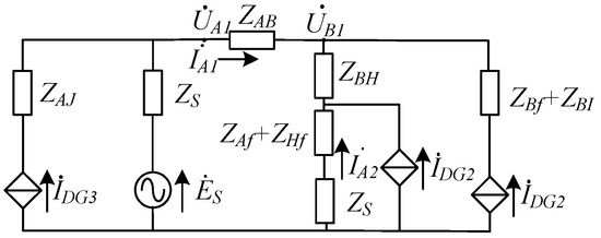
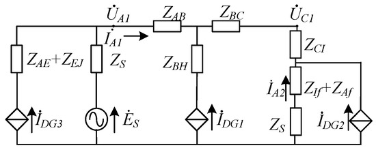
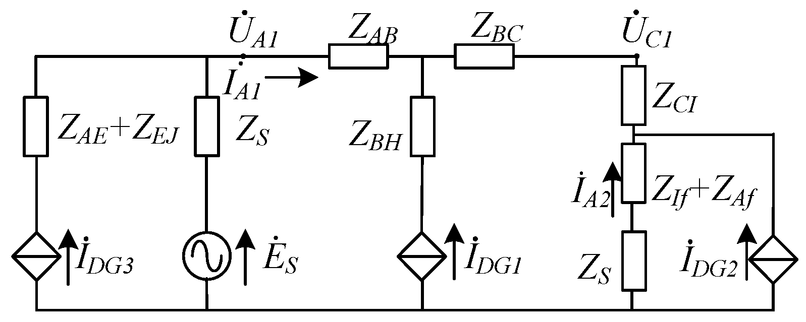
Figure 3 illustrates the composite sequence network of the ADN for a TPSCF occurring at f2.
Figure 3.
Composite Sequence Network for a TPSCF at f2.
The negative-sequence current flowing through protection 1 is shown in Equation (5).
3.1.3. At f3 on Line cd
Figure 4 illustrates the composite sequence network of the ADN for a TPSCF occurring at f3.
Figure 4.
Composite Sequence Network for a TPSCF at f3.
Similarly, the negative-sequence current flowing through Protection 1 is shown in Equation (6).
where represents the line impedance from point c (located on the line monitored by protection 1) to the fault point.
3.2. Faults on the Main Line of Feeder Y
3.2.1. At f4 on Line ae
Figure 5 illustrates the composite sequence network of the ADN for a TPSCF occurring at f4.
Figure 5.
Composite Sequence Network for a TPSCF at f4.
The negative-sequence current flowing through protection 2 is shown in Equation (7).
where represents the line impedance from point a (located on the line monitored by protection 2) to the fault point.
3.2.2. At f5 on Line ef
Figure 6 illustrates the composite sequence network of the ADN for a TPSCF occurring at f5.
Figure 6.
Composite Sequence Network for a TPSCF at f5.
The negative-sequence current flowing through protection 2 is shown in Equation (8).
where represents the line impedance from point e (located on the line monitored by protection 2) to the fault point.
3.2.3. At f6 on Line fg
When a TPSCF occurs at f6, the scenario is similar to that of a fault at f5.
3.3. Faults on Branch Lines
3.3.1. At f7 on Line bh
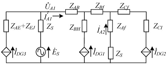
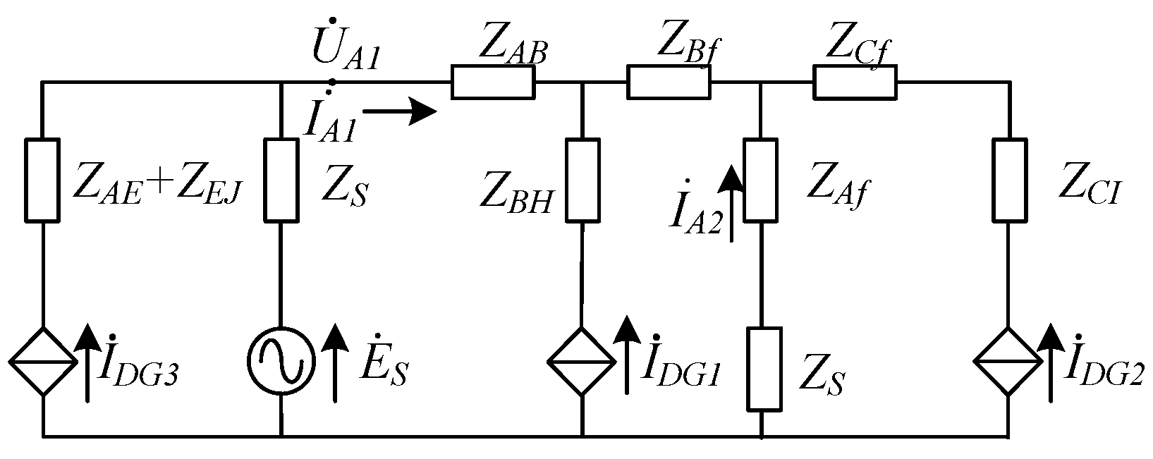
Figure 7 illustrates the composite sequence network of the ADN for a TPSCF occurring at f7.
Figure 7.
Composite Sequence Network for a TPSCF at f7.
The negative-sequence current flowing through protection 3 is shown in Equation (9):
where represents the positive-sequence voltage measured at protection CB3, and represents the line impedance from point b (located on the line monitored by protection 3) to the fault point.
3.3.2. At f8 on Line hk
Figure 8 illustrates the composite sequence network of the ADN for a TPSCF occurring at f8.
Figure 8.
Composite Sequence Network for a TPSCF at f8.
The negative-sequence current flowing through protection 3 is shown in Equation (10).
where represents the line impedance from point h (located on the line monitored by protection 3) to the fault point.
3.3.3. At f9 on Line ci
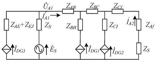
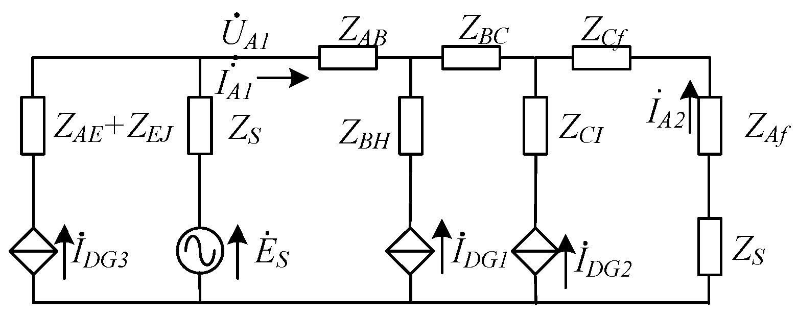
Figure 9 illustrates the composite sequence network of the ADN for a TPSCF occurring at f9.
Figure 9.
Composite Sequence Network for a TPSCF at f9.
The negative-sequence current flowing through protection 4 is shown in Equation (11).
where represents the positive-sequence voltage measured at protection CB4, and represents the line impedance from point c (located on the line monitored by protection 4) to the fault point.
3.3.4. At f10 on Line il
Figure 10 illustrates the composite sequence network of the ADN for a TPSCF occurring at f10.
Figure 10.
Composite Sequence Network for a TPSCF at f10.
The negative-sequence current flowing through protection 4 is shown in Equation (12).
where represents the line impedance from point i (located on the line monitored by protection 4) to the fault point.
3.3.5. At f11 on Line ej
When a TPSCF occurs at f11, the scenario is similar to that of a fault at f7.
3.3.6. At f12 on Line jm
When a TPSCF occurs at f12, the scenario is similar to that of a fault at f8.
3.3.7. At f13 on the Branch Line Without the IIDG of Feeder Y
Figure 11 illustrates the composite sequence network of the ADN for a TPSCF occurring at f13.
Figure 11.
Composite Sequence Network for a TPSCF at f13.
The negative-sequence current flowing through protection 4 is shown in Equation (13).
where represents the line impedance from point F (located on the line monitored by protection 6) to the fault point.
4. Adaptive Protection Setting Scheme for Incomplete Information DN Based on Integrated Sequence Components
4.1. Magnitude Criterion for Negative-Sequence Instantaneous Trip Protection During TPSCFs
This study focuses on TPSCFs in ADNs within remote rural areas. Due to inherent infrastructure limitations and incomplete post-fault electrical information, this paper proposes to fully utilize the sequence components measured at feeder head-end protection installations for adaptive protection settings. When determining protection settings and considering the intermittent output fluctuations of IIDGs, we assume that IIDGs remain in an intermediate output state during faults to ensure protection reliability. Accordingly, the method establishes the negative-sequence current magnitude measured at the feeder head-end when a TPSCF occurs at a line terminal. Compared to traditional adaptive protection methods, the proposed method incorporates IIDG output currents and significantly extends protection coverage. Therefore, denoting , , and as the output current magnitudes of IIDG1, IIDG2, and IIDG3 under two-phase fault conditions, respectively, this paper uniformly sets them at 0.8 times the rated output current of IIDGs.
4.1.1. Faults on the Main Line of Feeder X
- (1)
- At f1 on line ab
Based on the relationship between and at protection 1 during a TPSCF on line ab, Equation (14) is derived from Equation (3):
where is the impedance of line ab, protected by protection 1. characterizes the normalized distance to the fault point, taking a value in the range [0, 1].
The setting of for Protection 1, required to cover line ab completely, is shown in Equation (15).
where represents the reliability factor. To ensure full-length line protection under fault conditions, it is set to 0.9 in this context. represents , that is, the phase difference between the positive-sequence voltage at the feeder outlet and . As established in Ref. [24], the phase difference between the voltage measured at the feeder outlet protection point and grid connection point voltages of IIDGs at different locations remains minimal, never exceeding 8°. Additionally, considering IIDGs exclusively output reactive current during this condition, lags the grid connection point voltage by 90°. To maximize the protection coverage range, the setting is determined under the condition of .
- (2)
- At f2 on line bc
Using the relationship in Equation (5) for the negative-sequence current and positive-sequence voltage at Protection 1 during a TPSCF on line bc, the corresponding protection setting value for the line bc segment is shown in Equation (16):
- (3)
- At f3 on line cd
Using the relationship in Equation (6) for the negative-sequence current and positive-sequence voltage at Protection 1 during a TPSCF on line cd, the corresponding protection setting value for the line cd segment is shown in Equation (17).
4.1.2. Faults on the Branch Lines of Feeder X
- (1)
- At f7 on line bh
Using the relationship in Equation (9) for the negative-sequence current and positive-sequence voltage at Protection 1 during a TPSCF on line bh, the corresponding protection setting value for the line bh segment is shown in Equation (18).
In order to ensure the selectivity and high-speed operation of protection 3, is set to 1.1. Additionally, for coordination with the backup protection of the main line, a current directional element is installed on the bh line to prevent maloperation of protection 1 during faults on the branch line.
- (2)
- At f8 on line hk
Using the relationship in Equation (10) for the negative-sequence current and positive-sequence voltage at Protection 1 during a TPSCF on line hk, the corresponding protection setting value for the line hk segment is shown in Equation (19).
where, to guarantee complete line coverage by Protection 3, is set to 0.9.
- (3)
- At f9 on line ci
Using the relationship in Equation (11) for the negative-sequence current and positive-sequence voltage at Protection 1 during a TPSCF on line ci, the corresponding protection setting value for the line ci segment is shown in Equation (20).
Similar to line bh, to ensure the selectivity and high-speed operation of protection 4, is set to 1.1, along with the installation of a current directional element on the line ci.
- (4)
- At f10 on line il
Using the relationship in Equation (12) for the negative-sequence current and positive-sequence voltage at Protection 1 during a TPSCF on line il, the corresponding protection setting value for the line il segment is shown in Equation (21):
where, to guarantee complete line coverage by Protection 4, is set to 0.9.
4.1.3. Faults on the Main Line of Feeder Y
- (1)
- At f4 on line ae
This protective configuration follows the same logic as that applied to line ab of feeder X.
- (2)
- At f5 and f6 on line eg
This protective configuration follows the same logic as that applied to line bc of feeder X.
4.1.4. Faults on the Branch Lines of Feeder Y
- (1)
- At f11 on line ej
This protective configuration follows the same logic as that applied to line bh.
- (2)
- At f12 on line jm
This protective configuration follows the same logic as that applied to line hk.
- (3)
- At f13 on the branch line without the IIDG of feeder Y
Using the relationship in Equation (13) for the negative-sequence current and positive-sequence voltage at Protection 1 during a TPSCF on line fn, the corresponding protection setting value for the line fn segment is shown in Equation (22).
4.2. Explanation of Protection Action Process
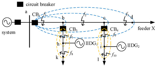
The paper proposes an adaptive protection scheme that utilizes multiple setting groups for different line segments to address incomplete data scenarios. The specific fault location is diagnosed by monitoring the operation status of the protection units across these segments. The setting ranges for each protection zone are illustrated in Figure 12.
Figure 12.
Diagram illustrating the protection range of feeder X.
Taking the feeder X shown in Figure 12 as an example, when a TPSCF occurs on line bc, protection 1 will satisfy the operation criteria for the amplitude setting values of lines bc, cd, and ci. However, the current directional element installed on line ci ensures that protection 4 does not operate incorrectly. Thus, protection 1 can successfully isolate the faulted line. Meanwhile, according to the amplitude criterion, since the amplitude setting value of line ab does not satisfy the operation criteria, the fault is determined to be located on line bc.
During a TPSCF, the transition resistance is relatively small, generally not exceeding 10 Ω, and it typically increases rapidly within 0.1–0.15 s after the fault [25]. In the specific scenario of TPSCFs examined in this study, due to the small initial transition resistance value and the fast response and online updating capabilities of the proposed adaptive setting method, simulations indicate that the dynamic variation of transition resistance had minimal impact on the stable trend of protection setting values. Therefore, the transition resistance has a limited effect on the proposed method.
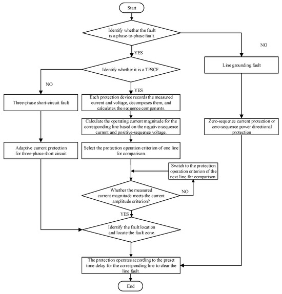
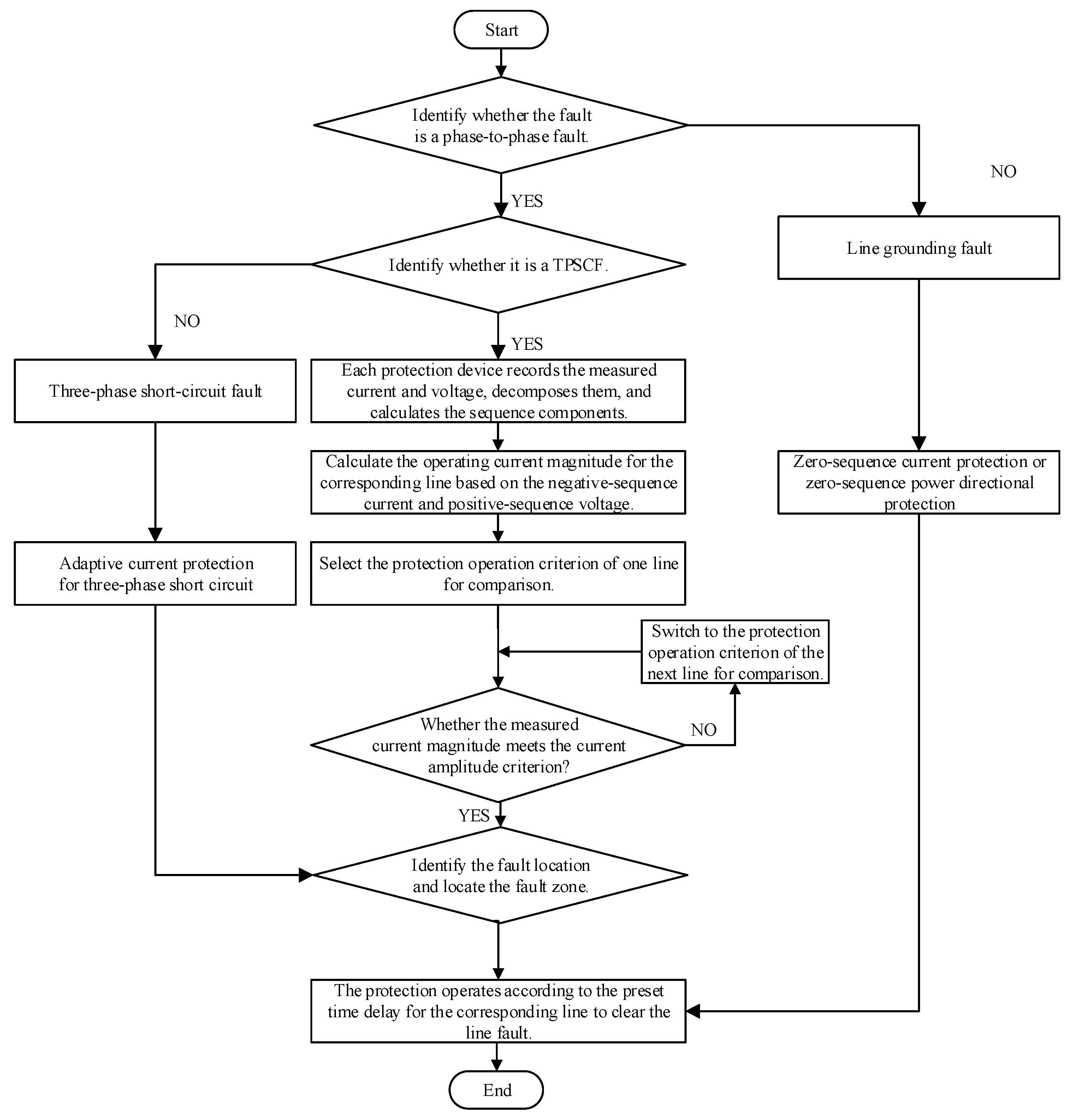
Following the analysis of fault characteristics and the protection methodology, Figure 13 shows the resulting flowchart of the proposed protection scheme. Upon fault occurrence, preliminary fault type identification is first conducted based on the presence or absence of zero-sequence components. If it is an inter-phase fault, further determination of whether it is a TPSCF is made according to the magnitude of negative-sequence components. In the case of a TPSCF, the protection device collects data such as current and voltage signals, decomposes them, and calculates the sequence components. Subsequently, the operating current amplitude of the corresponding line is computed using the decomposed negative-sequence current and positive-sequence voltage. A single-line protection operation criterion is selected for comparison. If the condition is not satisfied, the system switches to the next line criterion and repeats the comparison until the current amplitude condition is met. Once satisfied, the fault location and section are determined, and the faulty line is tripped according to the preset operating time of the corresponding line. If it is not a TPSCF, the fault is identified as a three-phase short-circuit, triggering the adaptive current protection for three-phase faults proposed in Ref. [24]. If the initial judgment indicates a non-inter-phase fault, it is concluded that a grounding fault has occurred. Corresponding protection methods, such as zero-sequence current protection or zero-sequence power directional protection, can then be applied. Through hierarchical identification and adaptive criterion switching, the above process achieves rapid and precise fault location and isolation.
Figure 13.
Protection Action Flowchart.
5. Example and Simulation Analysis
Using PSCAD/EMTDC v4.6.2 simulation software, the model of an ADN shown in Figure 1 is constructed to validate the adaptive negative-sequence instantaneous overcurrent protection under TPSCFs. With faults on both the main line and branch lines of feeder X as examples, simulation verifications are conducted respectively for faults at different locations and cases with different IIDG capacities. The simulation results are shown in Table 1, Table 2 and Table 3. characterizes the normalized distance to the fault point, taking a value in the range [0, 1]. IZD-X represents the negative-sequence current amplitude setting value at protection installation point X for the corresponding line. I2-X indicates the measured negative-sequence current amplitude at protection installation point X during the fault.
Table 1.
Simulation results of protection 1 action in case of TPSCF.
Table 2.
Simulation results of protection 3 action in case of TPSCF.
Table 3.
Simulation results of protection 1 action during TPSCF under different IIDG capacities.
5.1. Faults on the Main Lines
The simulation results in Table 1 indicate that, under different fault locations and fault distance coefficients (0.2–0.8), the negative-sequence current I2-X at Protection 1 is significantly greater than the setting current IZD-X of the corresponding line, thereby ensuring correct operation of the protection during main-line faults. This demonstrates that the starting criterion of the proposed adaptive protection method possesses sufficient sensitivity: it can reliably detect fault occurrences within the line range and ensure correct protection operation. Furthermore, when a fault occurs on line bc, the negative-sequence current I2-BC at Protection 1 exceeds the setting currents IZD-BC and IZD-CD corresponding to lines bc and cd, meeting the operation criteria for lines bc and cd, but is less than the setting value IZD-AB corresponding to line AB at this time. According to the proposed fault-section discrimination logic, it can be determined that the fault occurs on line bc, effectively validating the proposed method’s capability in identifying fault sections. By comparing data under different α values, it is evident that the protection actions exhibit good consistency. Simulation results also show that the method offers notable advantages in speed and reliability, confirming the applicability of the adaptive protection method in complex fault scenarios.
5.2. Faults on the Branch Lines
The tabular data in Table 2 demonstrate that during faults on branch lines bh and hk with varying fault distance coefficients , the decomposed negative-sequence current I2-X at protection 3 consistently exceeds the corresponding line current setting values IZD-BH and IZD-HK. This verifies the proposed method’s capability to identify fault zones on branch lines while maintaining both sensitivity and reliability. Simultaneously, the faulted section can be identified by determining whether the operation criteria are satisfied, and the transition resistance has a limited impact on the criteria, which validates the method’s practical feasibility under complex fault conditions.
5.3. Feasibility Analysis of the Method When the IIDG Capacity Changes
Taking faults on the main line segment AB of feeder X with different IIDG capacities as examples, simulation verifications are conducted, and the simulation results are shown in Table 3.
The data in Table 3 indicate that, under different IIDG capacity integrations, the negative-sequence current I2-X at Protection 1 significantly exceeds the setting current IZD-X of the corresponding line, thus ensuring correct protection operation during main-line faults. This indicates that the method remains feasible when IIDG capacities vary. Furthermore, as IIDG capacities change, the setting values of each segmented line exhibit minor variations, validating that the method is unaffected by IIDG capacity fluctuations and effectively expanding its feasibility.
6. Conclusions
This paper addresses the challenge of adaptive current protection in distribution networks under conditions of limited protection installations and insufficient communication, considering the impact of integrating multiple IIDGs. Focusing on TPSCFs and utilizing only the electrical measurements available at the feeder head-end, an adaptive current protection method for ADNs based on integrated sequence components is proposed. First, by analyzing the fault characteristics during TPSCFs at different locations within the ADN structure, a relationship is established between the negative-sequence current and the positive-sequence voltage at the feeder head-end, using line impedance parameters and IIDG fault output characteristics. Subsequently, the measured currents and voltages at the protection point are decomposed to obtain the amplitudes of the negative-sequence current and positive-sequence voltage. This allows for the real-time determination of protection operation criteria for each zone, enabling accurate fault section identification. Finally, an ADN model with high-penetration IIDG integration is implemented in PSCAD/EMTDC to validate the proposed method.
The results confirm that the proposed method is simple, effective, easy to implement, and communication-independent, thereby significantly improving protection reliability and sensitivity.
The main advantages of the proposed method over conventional protection schemes are as follows:
- (1)
- The method fully utilizes electrical measurements from the main and branch line head-ends without requiring additional protection devices. This enables comprehensive line protection and preliminary fault-zone identification in ADNs with minimal information, leading to a significant reduction in protection configuration costs.
- (2)
- The method dynamically calculates the equivalent system impedance using real-time negative-sequence current and voltage measurements at the feeder head-end, providing strong adaptability to varying system operating conditions.
- (3)
- The method accounts for the influence of IIDGs on fault currents while being unaffected by specific IIDG locations, thereby substantially enhancing protection reliability.
- (4)
- The integration of directional elements with traditional current-based adaptive protection on branch lines prevents maloperation of the main feeder protection, enabling more reliable adaptive functionality.
- (5)
- The use of positive- and negative-sequence components for protection criteria improves sensitivity for asymmetrical faults and effectively addresses maloperation or failure-to-operate issues caused by IIDGs.
- (6)
- Designed to operate entirely on local information, the method offers high reliability, simplicity, and ease of implementation. It applies to multi-feeder systems and possesses considerable scalability, along with low cost and straightforward engineering deployment.
Based on the current reality that a large number of legacy IIDGs compliant with the GB/T 19964-2012 standard in China remain operational in remote areas of China, this study primarily focuses on such IIDGs. For IIDGs conforming to the latest standards like IEEE 1547-2018, which possess unbalanced fault current injection capabilities, re-evaluation and adaptive improvements may be necessary. In future work, it is necessary to integrate factors such as other fault types and complex distribution network topologies, including weakly meshed networks with normally closed-loop operation; conduct in-depth research on adaptive current protection in ADNs; and expand the application scenarios and feasibility of the method.
Author Contributions
Conceptualization, S.S.; methodology, Y.L., X.H., F.H., Y.G., J.L., X.C. and B.L.; resources, S.S., Y.L., X.H., F.H. and Y.G.; funding acquisition, S.S., Y.L., X.H., F.H., Y.G. and B.L.; writing—original draft, J.L.; writing—review and editing, X.C. and J.Z.; visualization, J.L. All authors have read and agreed to the published version of the manuscript.
Funding
This research was funded by Yunnan Fundamental Research Projects, grant number No.202401CF070077.
Data Availability Statement
Due to the nature of this research, participants of this study did not agree for their data to be shared publicly, so supporting data is not available.
Conflicts of Interest
Author Shi Su, Yuan Li, Xuehao He, and Faping Hu were employed by the Yunnan Power Grid Company Electric Power Research Institute. This study received funding from Yunnan Power Grid Co., Ltd. under Yunnan Fundamental Research Projects No. 202401CF070077. The funder was involved in the study design, methodology development, investigation, resource provision, and funding acquisition. All data analysis, interpretation of results, and manuscript writing were performed independently by the authors and were not subject to any undue influence from the funder. The authors declare no other competing financial or non-financial interests.
Abbreviations
The following abbreviations are used in this manuscript:
| IIDG | Inverter-interfaced distributed generator |
| DN | Distribution network |
| ADN | Active distribution network |
| TPSCF | Two-phase short-circuit fault |
| CT | Current transformer |
References
- Zhao, Y.; Zhang, G.; Hu, W.; Huang, Q.; Chen, Z.; Blaabjerg, F. Meta-learning based voltage control for renewable energy integrated active distribution network against topology change. IEEE Trans. Power Syst. 2023, 38, 5937–5940. [Google Scholar] [CrossRef]
- Gao, S.; Yu, H.; Li, P.; Ji, H.; Yu, J.; Zhao, J.; Song, G.; Wu, J. Randomly switched subsystem-based state estimation for active distribution networks with unobservable conditions. IEEE Trans. Instrum. Meas. 2025, 74, 1–14. [Google Scholar] [CrossRef]
- Hou, S.; Wang, W. Fault-line selection method in active distribution networks based on improved multivariate variational mode decomposition and lightweight YOLOv10 network. Energies 2024, 17, 4958. [Google Scholar] [CrossRef]
- Prasad, M.; Rather, Z.H.; Razzaghi, R.; Doolla, S. A New Approach to Determine Feasible Operating Region of Unbalanced Distribution Networks with Distributed Photovoltaics. IEEE Trans. Power Deliv. 2025, 40, 1493–1504. [Google Scholar] [CrossRef]
- Gutierrez-Rojas, D.; Nardelli, P.H.J.; Mendes, G.; Popovski, P. Review of the state of the art on adaptive protection for microgrids based on communications. IEEE Trans. Ind. Inform. 2020, 17, 1539–1552. [Google Scholar] [CrossRef]
- Zheng, X.; Chao, C.; Weng, Y.; Ye, H.; Liu, Z.; Gao, P.; Tai, N. High-frequency fault analysis-based pilot protection scheme for a distribution network with high photovoltaic penetration. IEEE Trans. Smart Grid 2022, 14, 302–314. [Google Scholar] [CrossRef]
- Yan, Y.; Ao, F.; Liu, H.; Xu, B.; Wu, J.; Li, H.; Li, Y.; Hu, S. Novel Self-adjusted Full-line Current Protection Strategy for Small Resistance Grounding Distribution Network. Chin. J. Electr. Eng. 2024, 10, 83–96. [Google Scholar] [CrossRef]
- Yu, H.; Lu, Z.; Liu, Y.; Gao, Y.; Wan, J. Injected Harmonic Feature Based Protection Scheme for Active Distribution Networks With High Proportion IIDGs. IEEE Access 2024, 12, 35282–35299. [Google Scholar] [CrossRef]
- Zhang, C.; Song, G.; Wang, T.; Dong, X. An improved non-unit traveling wave protection method with adaptive threshold value and its application in HVDC grids. IEEE Trans. Power Deliv. 2019, 35, 1800–1811. [Google Scholar] [CrossRef]
- Zhang, Y.; Yu, Y.; Yang, G. Adaptive current differential protection principle for transmission line connected to energy storage power station based on phase and amplitude compensation. J. Energy Storage 2025, 111, 115468. [Google Scholar] [CrossRef]
- Qiao, Y.; Wu, H.; Wu, T.; Li, X. A Partitioned Current Protection Scheme of Distribution Network with Inverter Interfaced Distributed Generator. Trans. China Electrotech. Soc. 2022, 37, 134–144. [Google Scholar]
- Chen, G.; Liu, Y.; Yang, Q. Impedance differential protection for active distribution network. IEEE Trans. Power Deliv. 2020, 35, 25–36. [Google Scholar] [CrossRef]
- Sun, H.; Zhang, X.; Xu, H.; Guo, A.; Xie, S. A short-circuit protection scheme for active distribution networks based on improved adaptive current reliability coefficient. Meas. Sci. Technol. 2024, 36, 016204. [Google Scholar] [CrossRef]
- Yu, L.; Jia, K.; Wen, Z.; Zhang, Y.; Kong, F.; Bi, T. Adaptive setting method of over current protection in active distribution network considering measurement data missing. Autom. Electr. Power Syst. 2022, 46, 145–152. [Google Scholar]
- Wang, F.; Zhang, X.; Zhu, J.; Xu, H.; Sun, H.; Wang, W. Adaptive current protection scheme for distribution network with inverter-interfaced distributed generation. Electr. Power Syst. Res. 2025, 247, 111864. [Google Scholar] [CrossRef]
- Al-Odienat, A.I.; Al-Maitah, K. Local decision module for a more reliable wide area protection scheme. Int. J. Innov. Comput. Inf. Control 2021, 17, 671–685. [Google Scholar]
- Zhou, C.; Zou, G.; Du, X.; Zang, L. Adaptive current differential protection for active distribution network considering time synchronization error. Int. J. Electr. Power Energy Syst. 2022, 140, 108085. [Google Scholar] [CrossRef]
- Zhu, X.; Liu, X.; Yao, M.; Cui, Y.; Liu, K. Analysis and application of transient change of phase current under grounding fault in distribution network. Autom. Electr. Power Syst. 2022, 46, 187–196. [Google Scholar]
- GB/T 19964—2024; Technical Requirements for Connecting Photovoltaic Power Station to Power System. Standardization Administration of the People’s Republic of China: Beijing, China, 2024; pp. 1–20.
- IEEE Std 1547.2-2008; IEEE Application Guide for IEEE std 1547(TM), IEEE Standard for Interconnecting Distributed Resources with Electric Power Systems. IEEE Standards Association: Piscataway, NJ, USA, 2009; pp. 1–217.
- IEEE Std 1547.2-2023 (Revision of IEEE Std 1547.2-2008); IEEE Application Guide for IEEE std 1547TM-2018, IEEE Standard for Interconnection and Interoperability of Distributed Energy Resources with Associated Electric Power Systems Interfaces. IEEE Standards Association: Piscataway, NJ, USA, 2024; pp. 1–291.
- Crăciun, B.-I.; Kerekes, T.; Séra, D.; Teodorescu, R. Overview of Recent Grid Codes for PV Power Integration. In Proceedings of the 2012 13th International Conference on Optimization of Electrical and Electronic Equipment (OPTIM), Braşov, Romania, 24–26 May 2012; pp. 959–965. [Google Scholar]
- Li, J. Study on the Influence of Interconnecting Distributed Resources with Electric Power Systems and the Protection of Active Distribution Network. Master’s Thesis, Hefei University of Technology, Hefei, China, 2017. [Google Scholar]
- Su, S.; Li, Y.; He, X.; Xie, Q.; Chen, X.; Zheng, Z.; Li, B.; Zhang, J. Adaptive current protection for three-phase short-circuit faults in active distribution networks. IET Renew. Power Gener. 2024, 18, 4621–4637. [Google Scholar] [CrossRef]
- He, J.; Li, Y.; Dong, X.; Li, B. Relay Protection Principle of Power System, 4th ed.; China Electric Power Press: Beijing, China, 2010. [Google Scholar]

Disclaimer/Publisher’s Note: The statements, opinions and data contained in all publications are solely those of the individual author(s) and contributor(s) and not of MDPI and/or the editor(s). MDPI and/or the editor(s) disclaim responsibility for any injury to people or property resulting from any ideas, methods, instructions or products referred to in the content. |
© 2026 by the authors. Licensee MDPI, Basel, Switzerland. This article is an open access article distributed under the terms and conditions of the Creative Commons Attribution (CC BY) license.