


Abstract
To improve the dynamic response and steady-state frequency quality of a wind–storage coordinated system during primary frequency regulation, and to address the secondary frequency dip caused by rotor kinetic energy recovery when a doubly fed induction generator (DFIG)-based wind turbine (DFIG-WT) participates in frequency support, this paper proposes a coordinated wind–storage primary frequency regulation strategy. This strategy synergistically controls the wind turbine’s rotor kinetic energy recovery and exploits the advantages of hybrid energy storage system (HESS). During the DFIG-WT control stage, an adaptive weighted model is developed for the inertial and droop power contributions of the DFIG-WT based on the available rotor kinetic energy, enabling a rational distribution of primary frequency regulation power. In the control segment of HESS, an adaptive complementary filtering frequency division strategy is proposed. This approach integrates an adaptive adjustment method based on state of charge (SOC) to control both the battery energy storage system (BESS) and supercapacitor (SC). Additionally, the BESS assists in completing the rotor kinetic energy recovery process. Through simulation experiments, the results demonstrate that under operating conditions of 9 m/s wind speed and a 30 MW step disturbance, the proposed adaptive weight integrated inertia control elevates the frequency nadir to 49.84 Hz and reduces the secondary frequency dip to 0.0035 Hz. Under the control strategy where wind and storage coordinated participate in frequency regulation and BESS assist in rotor kinetic energy recovery, secondary frequency dips were eliminated, with steady-state frequency rising to 49.941 Hz. The applicability of this strategy was further validated under higher wind speeds and larger disturbance conditions.
1. Introduction
In recent years, against the backdrop of global efforts to combat climate change and promote green, low-carbon transformation, China has set dual carbon goals: achieving peak carbon emissions by 2030 and carbon neutrality by 2060 [1]. To realize these objectives, China is increasing the share of non-fossil energy and building a new power system centered on clean energy [2,3]. As the dual carbon goals advance, the penetration rate of new energy sources, particularly wind and solar power, continues to rise [4]. As the penetration rate of new energy sources continues to increase, the increasing number of renewable energy generators connected via power electronic interfaces is gradually replacing traditional synchronous generators. This transition has progressively weakened the inertia and primary frequency regulation capabilities of power systems [5]. After the disturbance, both the frequency nadir and the rate of change of frequency (ROCOF) are amplified. Consequently, the system becomes more susceptible to frequency excursions, instability, and even severe cascading failures during faults or large power fluctuations, posing significant challenges to grid frequency stability [6,7]. As a major component of future power systems, wind power features more flexible, faster wind-turbine control methods and response times. However, because the rotor speed is decoupled from the grid frequency, wind turbines exhibit a “zero-inertia” characteristic, which increases the difficulty of frequency regulation for the grid [8,9]. Beyond inertia/droop power regulation based on converters, active control methods for the aerodynamic side of wind turbine blades are also advancing. For instance, trailing-edge flaps (TEFs) alter local lift and stall characteristics to enhance aerodynamic performance and power output. Computational studies indicate that the TEF deflection angle has a significant influence on the power coefficient and lift-drag characteristics. Moreover, the optimal deflection angle varies with incoming wind speed, exhibiting typical operating-condition-dependent optimal control characteristics [10].
To ensure that the doubly fed induction generator (DFIG)-based wind turbine (DFIG-WT) can effectively participate in primary frequency regulation, current control methods primarily focus on droop control, inertia control, and integrated inertia control. When the system experiences a power deficit, DFIG-WT typically suppresses frequency dip by releasing rotor kinetic energy. Since a decrease in rotor speed accompanies kinetic energy release, the electromagnetic power of the DFIG-WT deviates from maximum power point tracking (MPPT) operation. After a DFIG-WT withdraws from primary frequency regulation, the rotor must absorb energy to resume its initial motion state, potentially triggering a secondary frequency dip. Therefore, coordinating the entire process—from kinetic energy release to withdrawal from frequency regulation and subsequent rotor energy recovery—while ensuring primary frequency regulation support, and achieving power handover with rapid-response resources like energy storage systems, represents a critical challenge in DFIG-WT frequency regulation research. Regarding droop control, Yang et al. [11] introduce an adaptive droop control method. The initial droop coefficient is set based on wind speed and adjusts over time in response to rotor speed and the duration of frequency regulation. Although the magnitude of the secondary frequency dip has been reduced, the kinetic energy released by the rotor has correspondingly decreased, failing to fully utilize the DFIG-WT’s frequency regulation capability. Boyle et al. [12] present an improved droop control scheme utilizing rotor speed control. By online correction of the DFIG-WT’s power-tracking coefficient based on system frequency deviation, it enables linear steady-state primary frequency regulation for a DFIG-WT solely through rotor speed control. However, this work primarily addresses the shortcomings of traditional droop control and lacks verification or discussion regarding secondary frequency dips and rotor kinetic energy recovery issues. He et al. [13] propose a closed-loop speed control scheme grounded on the rotor motion equations of DFIG-WT. It establishes a droop relationship between the DFIG-WT’s electromagnetic torque and the grid frequency, thereby enabling adaptive droop control based on the rotor speed. However, it did not establish a control mechanism for addressing secondary frequency dips.
With respect to inertial control, Liu et al. [14] address frequency oscillations caused by DFIG-WT participating in grid frequency regulation. It proposes an improved fuzzy control algorithm for the artificial bee colony (ABC). This approach controls the inertia output power of DFIG-WT via a fuzzy controller while optimizing the parameters using an ABC algorithm with a Gaussian drift mechanism. This enhances the DFIG-WT’s inertia response capability. Although the model describes the DFIG-WT withdrawing from frequency regulation and the battery energy storage system (BESS) providing power support, it fails to incorporate the power demand for rotor speed recovery and secondary frequency dip into the design. Consequently, it is difficult to guarantee effective suppression of secondary frequency dip issues from a fundamental mechanism perspective. Kheshti et al. [15] propose an inertia control strategy based on a Gaussian distribution. Upon detecting a power gap, the DFIG-WT utilizes available rotor kinetic energy to increase output power, then gradually reduces it along a Gaussian distribution trajectory controlled by the standard deviation parameter, thereby ensuring that the rotor speed converges to a stable equilibrium. Although it can smoothly withdraw the DFIG-WT from frequency regulation and prevent excessive release of rotor kinetic energy, the process of restoring the DFIG-WT’s rotor kinetic energy is not completed within a primary frequency regulation cycle. Ding et al. [16] employ frequency deviation as input. It uses a fuzzy controller to adjust the DFIG-WT’s online inertia control coefficient based on external wind speed and frequency deviation, thereby achieving adaptive coupling among wind speed, frequency deviation, and virtual inertia. However, it similarly lacks modeling and analysis for secondary frequency dips.
In the integrated control of DFIG-WT, Wu et al. [17] propose an inertia enhancement method integrating inertial control with an improved phase-locked loop (PLL). Building on conventional rotor side vector control, it superimposes a comprehensive inertial control element—driven jointly by frequency deviation and ROCOF—onto the active power reference channel. This integrated inertial control is then embedded in the PLL, enabling it to respond more precisely to grid frequency fluctuations. Chen et al. [18] proposed an adaptive integrated inertial control strategy combining virtual inertia and droop control. For the adaptive coefficients, chaos game optimization (CGO) was selected to obtain optimal control parameters. Chen et al. [19] adaptively tune the inertia and droop control coefficients in response to grid frequency fluctuations. Specifically, the inertia control coefficient varies with the rotor speed and the system frequency and becomes zero after the system frequency nadir is reached. The droop control coefficient varies with frequency before a predefined time, remains constant from that time to the frequency nadir, and then gradually decreases to zero after the nadir. The above three references only address the secondary frequency dips issue at the coefficient control level, but none have designed corresponding control strategies specifically for secondary frequency dips.
Although the aforementioned studies have improved the frequency nadir to some extent and attempted to mitigate the secondary frequency dip phenomenon, they remain focused on tuning or optimizing droop and inertia control coefficients. They fail to consider how to more fully utilize the frequency regulation capability of rotor kinetic energy. There is a lack of targeted modeling and control design for the energy absorption process during speed recovery after kinetic energy release in DFIG-WT systems, as well as a deficiency in wind storage power relay and recovery coordination mechanisms specifically addressing secondary frequency dip.
Energy storage systems, due to their quick response and flexible control, can be used to address the limitations of DFIG-WT participating in primary frequency regulation during grid connection [20,21,22]. Zhang et al. [23] propose a wind–storage coordinated control strategy based on virtual inertia, in which a BESS assists wind turbines in frequency regulation. The BESS power output is constrained by its state of charge (SOC) to prevent overcharge and overdischarge, thereby mitigating battery degradation and extending its service life. Shang et al. [24] propose a fast frequency- and voltage-regulation method for BESS based on an amplitude-phase-locked loop (APLL). This method designs an inertial control strategy for primary frequency regulation based on the grid frequency deviation and ROCOF signals detected by the APLL. It avoids complex and sensitive differential calculations while achieving good dynamic support performance. Liu et al. [25] position the BESS’s frequency regulation dead zone within that of conventional units. It proposes a comprehensive inertia control strategy that determines the action sequence based on the current frequency deviation of the power system and the BESS’s SOC. This approach reduces the number of actions required of thermal power units while extending the BESS’s service life. Additionally, supercapacitor (SC) delivers millisecond-level response times, enabling instantaneous support for high-frequency, short-duration power surges in the grid. When integrated with BESS to form hybrid energy storage system (HESS), they address the limitations inherent in standalone BESS, thereby providing comprehensive solutions for all grid frequency fluctuation scenarios. Zhou et al. [26] and Wen et al. [27] both model the internal power allocation of HESS as frequency component decomposition based on a first-order low-pass filter. By utilizing a first-order low-pass filter stage with a fixed time constant, grid frequency deviations are decomposed into high-frequency and low-frequency components for allocation. While this approach features a simple structure and is easy to implement in engineering practice, the fixed time constant of the first-order low-pass filter prevents the power distribution within HESS from being able to adaptively regulate based on actual grid conditions.
In summary, the current coordinated wind-storage primary frequency regulation control strategy faces the following issues: On the DFIG-WT side, efforts primarily focus on tuning or optimizing inertia and droop coefficients, failing to fully leverage the frequency regulation capability of rotor kinetic energy. Additionally, there is a lack of closed-loop coordinated control throughout the entire process of rotor kinetic energy release, deregulation of DFIG-WT, and rotor kinetic energy recovery, making it difficult to mechanistically suppress secondary frequency dips. On the HESS side, the use of fixed-time-constant low-pass filters for internal power allocation within HESS prevents adaptive distribution based on actual grid conditions. This hinders the effective utilization of frequency regulation advantages offered by SC and BESS.
Therefore, this paper proposes a coordinated wind-storage primary frequency regulation strategy accounting for wind-turbine rotor kinetic energy recovery. On the DFIG-WT side, an adaptive weight allocation for inertia and droop output is established based on grid frequency deviation and ROCOF, combined with available rotor kinetic energy, to achieve integrated inertia control. This approach fully releases frequency regulation potential while ensuring compliance with lower speed limit safety constraints. Second, after the system frequency reaches its nadir, a negative exponential function is employed for a smooth exit. BESS is introduced to compensate for the power gap during the DFIG-WT exit phase and the power demand for speed recovery, forming a secondary frequency dip-oriented wind-storage power relay. Second, an adaptive complementary filtering frequency division mechanism is proposed for the HESS side. By integrating SOC constraints to dynamically adjust frequency division weights online, SC prioritizes handling high-frequency rapid components while BESS manages low-frequency energy components. This leverages their respective frequency regulation advantages, enhancing the HESS’s frequency support effectiveness while reducing BESS’s cycle counts and extending service life. Finally, simulation comparisons between the proposed strategy and alternative control approaches validate the effectiveness of the proposed control strategy.
2. Analysis of Power System Frequency Response and Characteristics Including DFIG-WT
2.1. Operational Model of DFIG-WT
DFIG-WT converts the received wind energy into mechanical energy, and the mechanical power is calculated using the following formula:
is the mechanical power of DFIG-WT, is the air density, is the swept area of the blades, is the power coefficient, is the wind speed, is the tip speed ratio, is the pitch angle [28]. The formula for calculating the wind energy utilization coefficient is as follows:
The formula for calculating the leaf tip speed ratio is as follows:
is the rotational speed of the rotor.
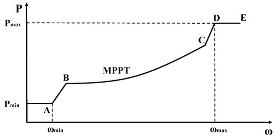
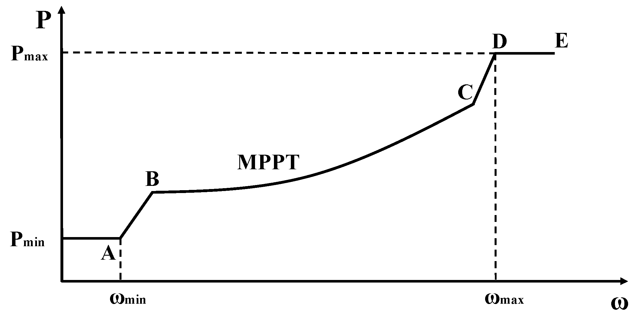
As shown in Figure 1, based on rotational speed, the DFIG-WT can be divided into four operating zones: the start-up zone (A–B), the MPPT zone (B–C), the constant-speed zone (C–D), and the constant-power zone (D–E). and represent the lower and upper limits of rotational speed for normal operation of the DFIG-WT. and denote the power corresponding to the lower and upper rotational speed limits. Subsequent power contributions from all DFIG-WT participating in primary frequency regulation are based on the MPPT. The maximum wind energy capture of the wind turbine can be achieved only when lambda reaches its optimal value. The MPPT power of the DFIG-WT is as follows:
where is the proportional coefficient of the MPPT curve for the DFIG-WT.
Figure 1.
Operating characteristics curve of DFIG-WT.
2.2. Integrated Inertial Control Model of DFIG-WT
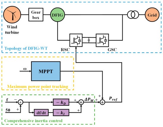
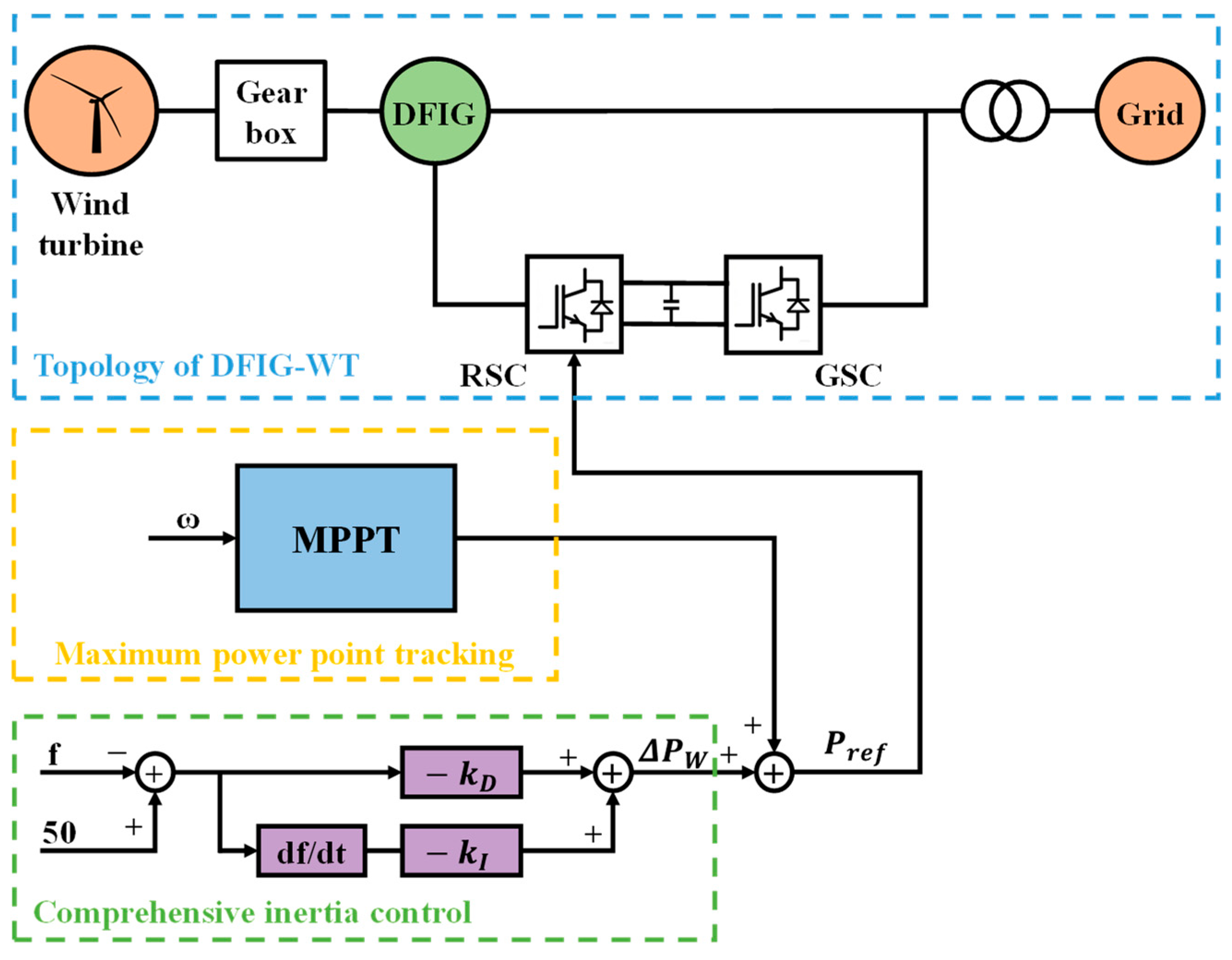
Integrated inertia control enables DFIG-WT to simulate the inertia response characteristics of conventional synchronous generators, thereby actively supporting grid frequency during fluctuations. The specific modeling principle is illustrated in Figure 2. The rotor-side converter (RSC) regulates electromagnetic torque and stator active/reactive power by adjusting rotor current to support variable-speed operation and MPPT. The grid-side converter (GSC) primarily maintains DC bus voltage and regulates grid-connected current/reactive power to ensure stable power exchange with the utility grid. When grid frequency fluctuates, the DFIG-WT generates additional power under integrated inertia control. This is combined with the existing power from the MPPT region to form the DFIG-WT’s reference power command . This command is input to the rotor-side converter to control the output power of the DFIG-WT.
Figure 2.
Integrated inertial control model for DFIG-WT.
The essence of DFIG-WT participation in grid frequency regulation lies in increasing electromagnetic power output by converting rotational kinetic energy into electrical power [29]. The rotor releases its kinetic energy, and the energy that the rotor can release during this process can be calculated using the following equation:
is the equivalent rotational inertia of the DFIG-WT.
As changes, the DFIG-WT’s output power is as follows:
During a grid frequency dip, the DFIG-WT releases rotor kinetic energy through integrated inertia control to generate additional power [30]. The additional power generated is as follows:
At this time, the reference power of the DFIG-WT is as follows:
The above equation indicates that when the grid frequency begins to decline, the ROCOF is relatively large while the frequency deviation is slight. As the frequency decreases, the frequency deviation increases, but the ROCOF gradually diminishes. Therefore, fixed-coefficient synthetic inertia control cannot dynamically adjust the DFIG-WT’s output to match actual grid conditions. This results in suboptimal dynamic and steady-state frequency characteristics of the grid and fails to leverage the DFIG-WT’s frequency regulation capabilities fully.
When DFIG-WT withdraws from primary frequency regulation, the abrupt shift in their operating point creates a power gap. This triggers the secondary frequency dip, with its severity increasing as the power gap widens. Without setting output limits or lower rotor speed protection thresholds for these turbines, the risk of excessive low-speed operation could even lead to turbine desynchronization.
2.3. Adaptive Weighted Integrated Inertia Control Strategy
Based on the analysis of the issues above, an adaptive weighted integrated inertia control strategy is proposed. During a decline in grid frequency, the inertia and droop outputs of DFIG-WT are weighted based on the available rotor kinetic energy. These weights are adaptively adjusted based on grid frequency deviation and the ROCOF, enabling more effective utilization of rotor kinetic energy to suppress frequency drops. After the frequency nadir is reached, the system frequency begins to recover. Accordingly, the DFIG-WT’s inertial power contribution is immediately withdrawn, while the droop power contribution is gradually ramped down following a negative exponential function. Meanwhile, rotor kinetic energy recovery is initiated to minimize the secondary frequency dip as much as possible.
2.3.1. Grid Frequency Decline Stage
During the implementation of comprehensive inertia control in wind turbines, the inertia output responds rapidly, enabling swift power delivery to suppress frequency drops. However, inertia output can only be sustained for a very short duration and consumes a significant amount of rotor kinetic energy. Without reasonable constraints, a secondary frequency dip or even more severe consequences may occur. Therefore, during the frequency decline phase, a comprehensive inertia control strategy is implemented by weighting the DFIG-WT’s rotor speed and the system’s frequency nadir as constraints.
First, the grid frequency deviation and the ROCOF undergo normalization processing. The normalization expression is as follows:
Among these, is the scaling constant that normalizes ROCOF, and is the scaling constant that normalizes . The value of is 0.2 Hz, and the value of is 0.8 Hz/s. According to the Technical Guidelines for Safety and Stability Control of China’s Power System GB/T 26399—2011 [31], the fundamental frequency difference should be set at 0.2 Hz, hence is selected as 0.2 Hz. According to the technical recommendations of the European Network of Transmission System Operators for Electricity (ENTSO-E) [32], the maximum recommended ROCOF magnitude for grid users to consider is 2 Hz/s. Based on the analysis of actual calculation examples, is selected as 0.8 Hz/s, which can satisfy the normalization requirements.
During the weight allocation process, when the system is undisturbed, the weights for inertia and droop outputs are equal. At the onset of frequency drop, is small while ROCOF is large, so the weight for the inertia output is increased. As the frequency continues to drop, the system’s increases progressively, while ROCOF decreases. At this point, the droop output weight must be increased. The weight allocation expression is as follows:
Among these, is the inertia weighting factor, is the droop weighting factor, is the baseline weighting factor without disturbance, is the inertia output control weighting factor, and is the droop output control weighting factor.
Additionally, in the proposed control strategy, the inertia control coefficient and droop control coefficient also adaptively vary with changes in and ROCOF. The expressions are as follows:
Among these, denotes the inertia adaptation factor, denotes the droop adaptation factor, and represent the inertia scaling reference and droop scaling reference under no disturbance, and are the inertia scaling control factors, while and are the droop scaling control factors.
The above formula indicates that as increases and ROCOF decreases, gradually diminishes, preventing excessive release of rotor kinetic energy that could cause secondary frequency dip. Simultaneously, progressively increases, providing more sustained support to the power grid.
2.3.2. Grid Frequency Recovery Stage
When the system frequency nadir, is reached or the rotor speed reaches the preset lower limit, the DFIG-WT’s inertia control immediately disengages to prevent further release of rotor kinetic energy. Simultaneously, droop control begins to disengage in a negative exponential manner. The use of an exponential decay function for the exit profile ensures continuous braking force, preventing abrupt changes, followed by natural attenuation. This significantly reduces the secondary frequency dip. The specific attenuation expression is as follows:
Among these, denotes the time corresponding to the frequency nadir, which can be obtained through ROCOF zero-crossing detection in real-time implementation. The decay time constant is critical: an excessively small value causes rapid disappearance of droop support, creating instantaneous power gaps; an excessively large value prolongs droop support, increasing the duration of DFIG-WT power deviation from MPPT. Based on first-order exponential decay characteristics, is set to 8 s.
Therefore, the coefficient expression for adaptive weighted integrated inertia control is as follows:
Among these, and represent the reference inertia and droop control coefficient, respectively.
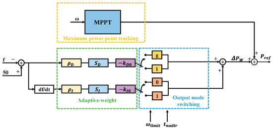
The adaptive-weight integrated inertia control model is shown in Figure 3. The in the image is the minimum limit value for rotor speed.
Figure 3.
Adaptive-weight integrated inertia control model for DFIG-WT.
3. Primary Frequency Regulation Strategy for Hybrid Energy Storage Systems
This section constructs an HESS comprising BESS and SC to participate in the primary frequency regulation of the power grid and assist in DFIG-WT rotor kinetic energy recovery. HESS achieves structural decoupling of power and energy, with SC handling high-frequency and transient power demands while BESS manages low-frequency and energy compensation. This configuration elevates the frequency nadir point and reduces the time required for frequency recovery and stabilization.
At the control layer of HESS, an SOC-based, logistically adaptive, inertia- and droop-coefficient control strategy is introduced. This strategy continuously adjusts the charging and discharging coefficients based on the storage system’s energy margin and operational status, balancing responsiveness with energy efficiency to effectively suppress secondary frequency dip. At the signal distribution layer, an adaptive complementary filter-based frequency-division control method is employed. The filter’s cutoff frequency dynamically adapts to frequency deviation and ROCOF, enabling high- and low-frequency signals to automatically adjust to actual grid conditions. This approach avoids the under- or overcompensation inherent in fixed-frequency division control, further leveraging the frequency regulation capabilities of BESS and SC to enhance power system stability.
3.1. Charge–Discharge Strategy Based on the Logistic Function
The comprehensive inertia control expression for the energy storage system is as follows:
Among these, is the inertia control coefficient of the energy storage system, and is the droop control coefficient of the energy storage system. When the grid frequency is within the frequency deadband, equals ; when the grid frequency is outside the frequency deadband, equals .
The control coefficient tuning method proposed in this paper, which accounts for SOC, employs a logistic function. The logistic function exhibits a continuous S-shaped curve, providing a smooth transition between the upper and lower limits of the output setting without any steps or abrupt changes. As the SOC approaches the set threshold, the charging and discharging rates naturally slow down to prevent issues such as polarization and overheating caused by abrupt current changes. In the intermediate range, the slope is steeper, enabling faster charging and discharging rates. The specific charge and discharge coefficient expressions are as follows:
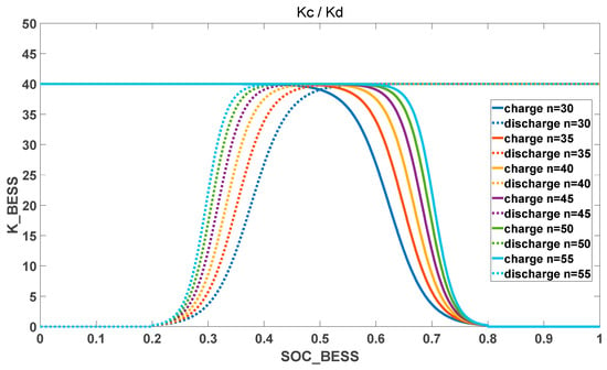
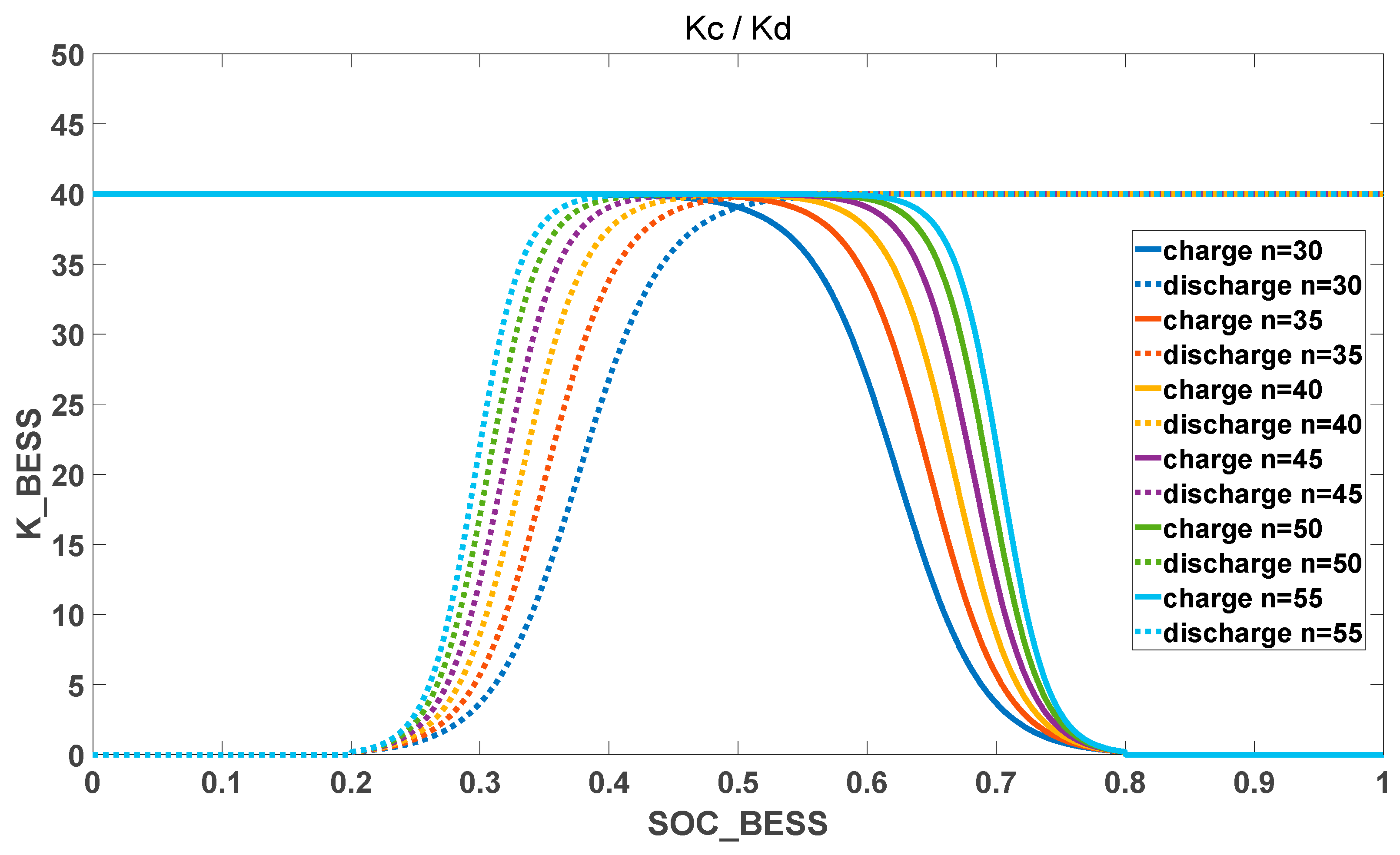
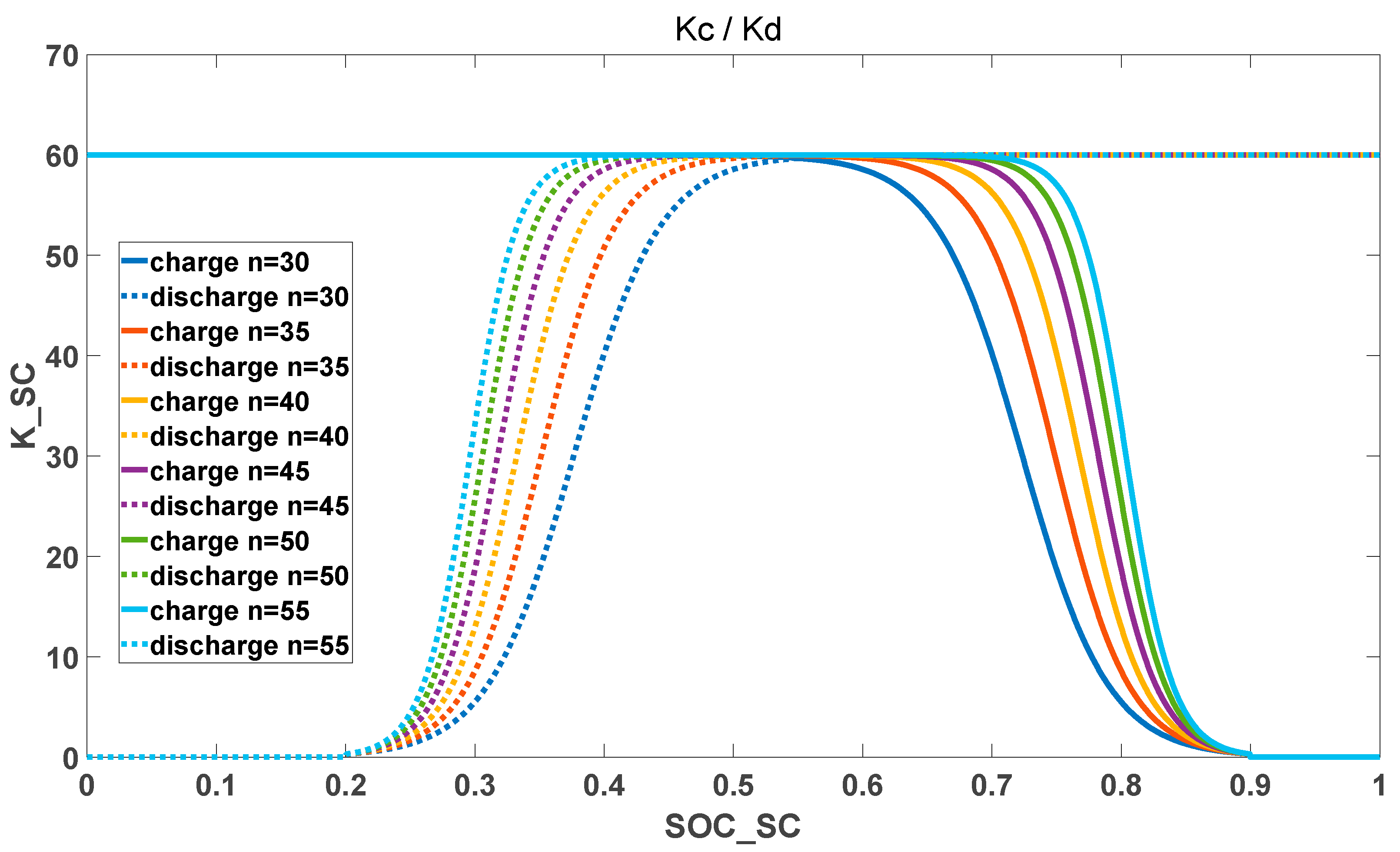
Among these, is the droop control coefficient during charging, is the droop control coefficient during discharging, . For the BESS, set = 40, = 0.2, = 0.8, For the SC, set = 60, = 0.2, = 0.9. This paper also employs for SC, but it denotes the normalized energy state of SC energy storage. This metric characterizes the available energy margin of SC, rather than the electrochemical state of charge. is the adjustment factor for the function curve. Changing the value of alters the rate of change of the charge–discharge coefficient. To determine the appropriate value of n through experimentation, the charge–discharge coefficient curves for BESS obtained from different values of n are shown in Figure 4, while the charge–discharge coefficient curves for SC are shown in Figure 5.
Figure 4.
Charge–discharge coefficients of BESS at different n values.
Figure 5.
Charge–discharge coefficients of SC at different n values.
In practical applications, it is generally desirable to maximize the duration during which the control coefficient remains at while simultaneously ensuring the slope does not become excessively steep. This prevents inducing power distribution fluctuations and rate saturation near the threshold. When the SOC approaches the threshold, the system should exit rapidly to avoid overcharging or overdischarging. Based on the above considerations, this paper conducted a parameter sensitivity analysis on n, comprehensively evaluating the frequency nadir, steady-state deviation, and changes in energy storage power. Ultimately, n = 45 was selected as the optimal compromise value between frequency performance and energy storage smoothness.
When the system frequency enters the recovery phase, the inertia output of the DFIG-WT is immediately shed, and droop control begins to exit in a negative exponential function form. This creates a power deficit in the DFIG-WT. At this point, the BESS increases its power output to compensate for this deficit and assist the DFIG-WT in restoring rotor kinetic energy. The expression for the BESS discharge coefficient is as follows:
3.2. Adaptive Complementary Filter Frequency Division
In traditional HESS employing high–low frequency division control, the use of a single low-pass filter with a fixed time constant prevents the crossover frequency from adapting to actual grid frequency variations. This may result in SC being responsible for high-frequency components responding too late or being overloaded by excessive power. Both scenarios compromise power system stability and reduce the operational lifespan of the energy storage system. However, directly altering the time constant of a single low-pass filter, or switching between two low-pass filters, can cause unnecessary oscillations due to abrupt changes in state or poles. Therefore, this paper proposes a dual low-pass crossover hybrid scheme that combines two low-pass filters and with different time constants. The weighting is determined based on the frequency regulation tasks undertaken by SC and BESS at different time scales and response speeds. The expressions for and are as follows:
, represent the time constants of the two filters, with set to 0.2 s and set to 1.2 s. According to the cutoff frequency formula:
The cutoff frequency of the two filters corresponding to angular frequencies of approximately 0.80 Hz and 0.13 Hz, respectively, the tendency to assign faster frequency fluctuation components to SC and slower components to BESS can be observed.
The expression for the cross-hybridization weight is as follows:
represents the frequency response factor, while and denote the maximum and minimum values of the blending weights. Given the small capacity and rapid response of SC, the SOC of the SC is used as a constraint in the equation.
Expression of the high-frequency signal and low-frequency signal after adaptive complementary filtering frequency division can be determined as follows:
The low-frequency signal after frequency division is directed to BESS, while the high-frequency signal is directed to SC.
3.3. Wind-Storage Combined Primary Frequency Regulation
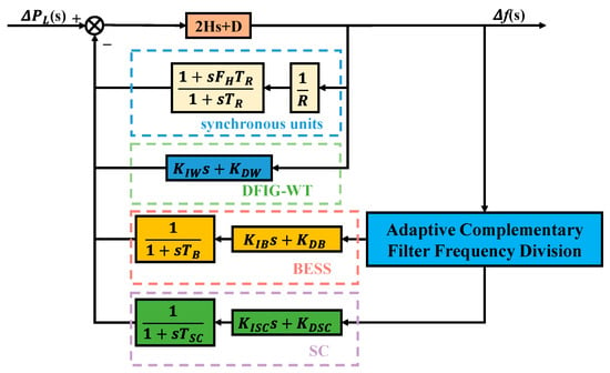
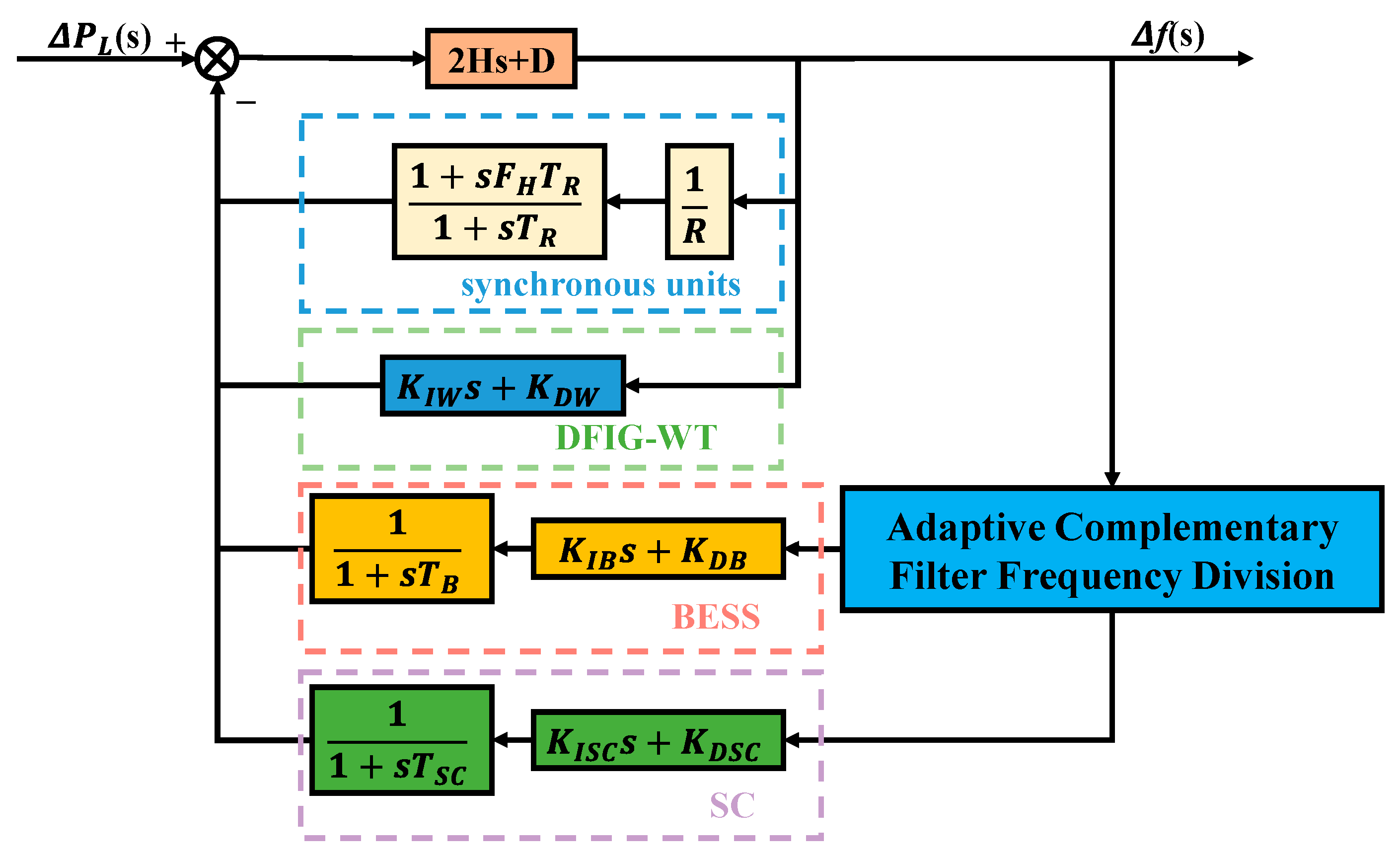
Based on the above analysis, a frequency response model for wind-storage combined primary frequency regulation has been established, as shown in Figure 6. It comprises four components: synchronous units, doubly fed induction generator (DFIG)-based wind turbine (DFIG-WT), battery energy storage system (BESS), and supercapacitor (SC). The net power imbalance of the system is jointly determined by the load disturbance and the support power provided by various frequency regulation resources, forming the frequency deviation through the equivalent inertia damping element (2Hs + D). Synchronous units provide traditional primary frequency regulation power, while DFIG-WT and HESS deliver power support according to the control strategy described earlier. The adaptive complementary filtering frequency division module adaptively decomposes frequency regulation demands into high-frequency and low-frequency components, assigning them to SC and BESS, respectively. This approach ensures the frequency regulation performance of the HESS while reducing the number of operations for the BESS, thereby extending its service life.
Figure 6.
Wind-storage combined frequency response model.
In the wind-storage coupled frequency response model, to simplify calculations, the adaptive complementary filter divider is approximated as a low-pass filter with a fixed time constant. The resulting low-frequency signal is denoted as (s) and the high-frequency signal as (s), expressed as follows:
The transfer functions for each frequency regulation channel in the system are as follows:
Therefore, the expression for the entire system is obtained as follows:
is the equivalent synchronous inertia constant, is the load damping coefficient, is the synchronous machine droop coefficient, is the lead coefficient of the synchronous machine primary frequency control channel, and is the first-order time constant of the synchronous machine primary frequency control channel. Due to the high order of this expression, simplification is required to facilitate the solution.
Select the angular frequency representing the lowest frequency band, expressed as follows:
Accordingly, the following expression is obtained.
denotes the magnitude of the low-frequency signal at denotes the magnitude of the high-frequency signal at , are the magnitudes of BESS and SC through the first-order link, is the equivalent droop magnitude of the synchronous machine at .
The equivalent inertia gain , droop gain , first-order time constant , effective inertia are synthesized from the above expressions. The specific expressions are as follows:
The expressions for in the above formula are as follows:
Approximate the entire system as a second-order single-zero system, expressed as follows:
In the formula:
Define standard second-order parameters:
Therefore, the time-domain response to the input step is as follows:
where
Therefore, the expression for the steady-state frequency difference and the initial ROCOF is obtained as follows:
The final expression for the time of the frequency nadir point is as follows:
At this instant, the grid frequency deviation, is given by the following:
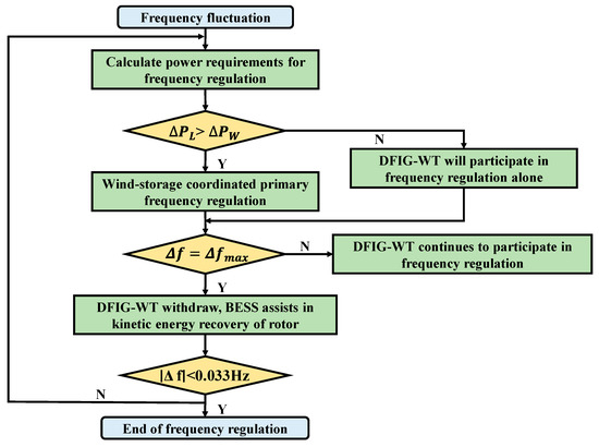
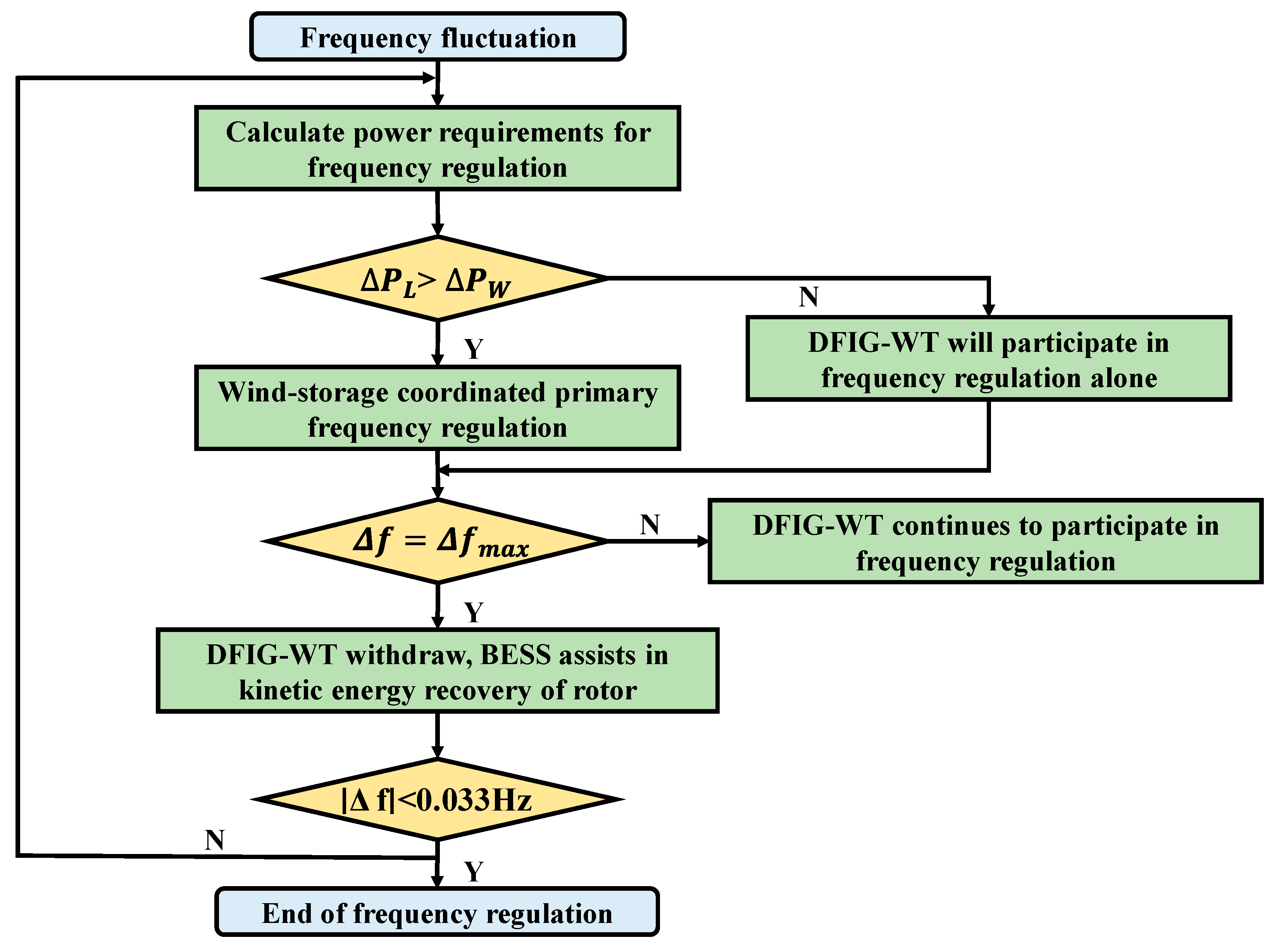
Based on the above analysis, the process flow for wind-storage coordinated primary frequency regulation is shown in Figure 7:
Figure 7.
Wind-storage coordinated primary frequency regulation control strategy.
Set the system’s frequency regulation dead zone to 0.033 Hz. Frequency fluctuations within this range will not trigger the system’s frequency regulation action. When the system frequency fluctuation exceeds the frequency regulation deadband, the required frequency regulation power is calculated and compared with the DFIG-WT’s available frequency regulation power. If the available frequency regulation power from the DFIG-WT is sufficient, the DFIG-WT will participate in frequency regulation alone. If insufficient, the DFIG-WT and energy storage system will jointly participate in frequency regulation.
After the system frequency reaches the nadir or the DFIG-WT rotor speed drops to the prescribed lower limit, the DFIG-WT’s inertial power contribution is immediately withdrawn, the droop power contribution is ramped down following a negative exponential function, and the droop coefficient of the BESS is adjusted to assist the DFIG-WT in restoring rotor kinetic energy. Once the system frequency deviation returns within the frequency regulation deadband, the frequency-support action terminates.
4. Case Study Analysis
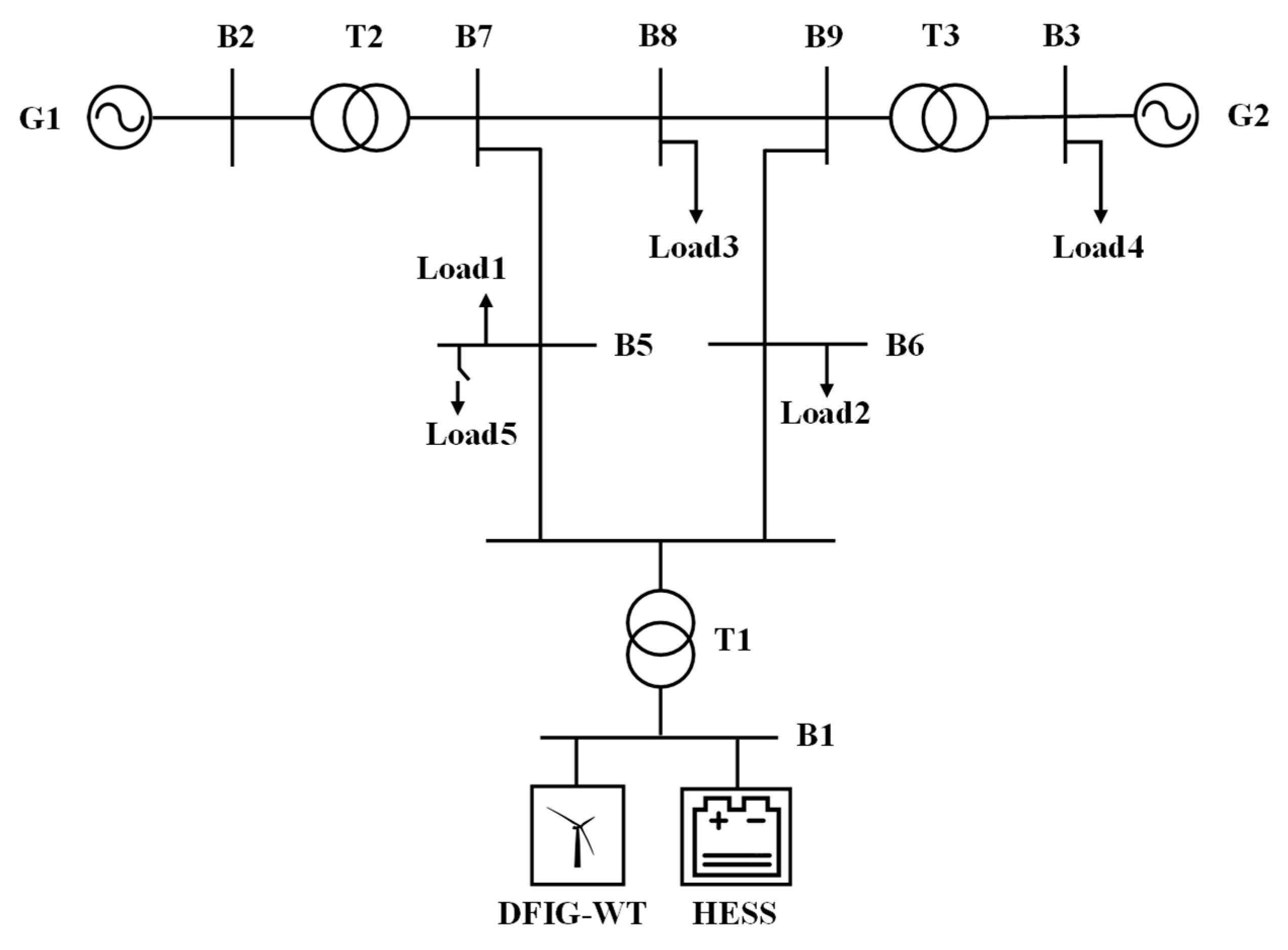
To validate the effectiveness of the proposed strategy, a three-machine, nine-node system was constructed in MATLAB/Simulink version R2024a as a test case for simulation verification. The structural diagram of this model is shown in Figure A1. At the 10 s, the system was disturbed by the addition of a variable load. The specific parameters for this example are listed in Table 1. The simulation experiments are divided into two main categories: 9 m/s and 11 m/s. These represent typical operating conditions for DFIG-WT under moderate and higher wind speeds, respectively. Both fall within the MPPT operating range, where pitch control is not engaged. This avoids interference from the pitch control loop on primary frequency regulation dynamics. Additionally, the 11 m/s condition more closely approximates the rated leading edge, featuring relatively higher rotational speed and available rotor kinetic energy reserves. This facilitates a comparative assessment of the proposed strategy’s robustness under varying kinetic energy release depths and energy recovery demands.
Table 1.
Calculation of example system parameters.
To enhance the interpretability and reproducibility of comparative validation, this paper selects the most commonly used control paradigm in wind-storage primary frequency regulation studies as the baseline scheme. A fair comparison is conducted under identical system models, identical disturbance conditions, and consistent clipping and SOC constraints. Specifically, the DFIG-WT side baseline scheme employs a typical fixed-coefficient synthetic inertia control, which is widely used in DFIG-WT frequency support studies and can be regarded as an industry-standard benchmark. The HESS side reference scheme employs a fixed-time-constant low-pass filter for high-to-low frequency signal allocation. This allocation method is widely adopted in HESS frequency regulation literature due to its simple structure and ease of implementation. Based on these two reference paradigms, this paper further establishes comparative schemes. To validate the effectiveness of the DFIG-WT control strategy, three experiments were conducted: (1) fixed-coefficient integrated inertia control, (2) variable-coefficient integrated inertia control, and (3) the adaptive weight control strategy proposed in this paper. To validate the effectiveness of the HESS control strategy, four experiments were conducted: (1) DFIG-WT adaptive weight control combined with BESS (AW-BESS), (2) DFIG-WT adaptive weight control combined with HESS employing fixed frequency division (AW-HESS-FFD), (3) DFIG-WT adaptive weight control combined with HESS employing adaptive complementary filtering frequency division (AW-HESS-ACFFD), and (4) DFIG-WT adaptive weight control combined with HESS employing adaptive complementary filtering frequency division, with BESS assisting wind turbine rotor kinetic energy recovery (AW-HESS-ACFFD-RKER).
4.1. Case 1 Study: 9 m/s Wind Speed with 30 MW Step Disturbance
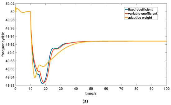
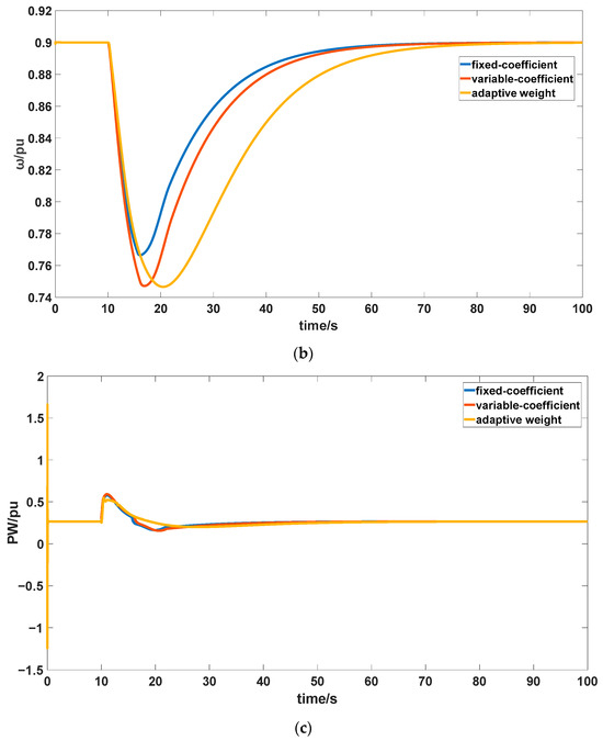
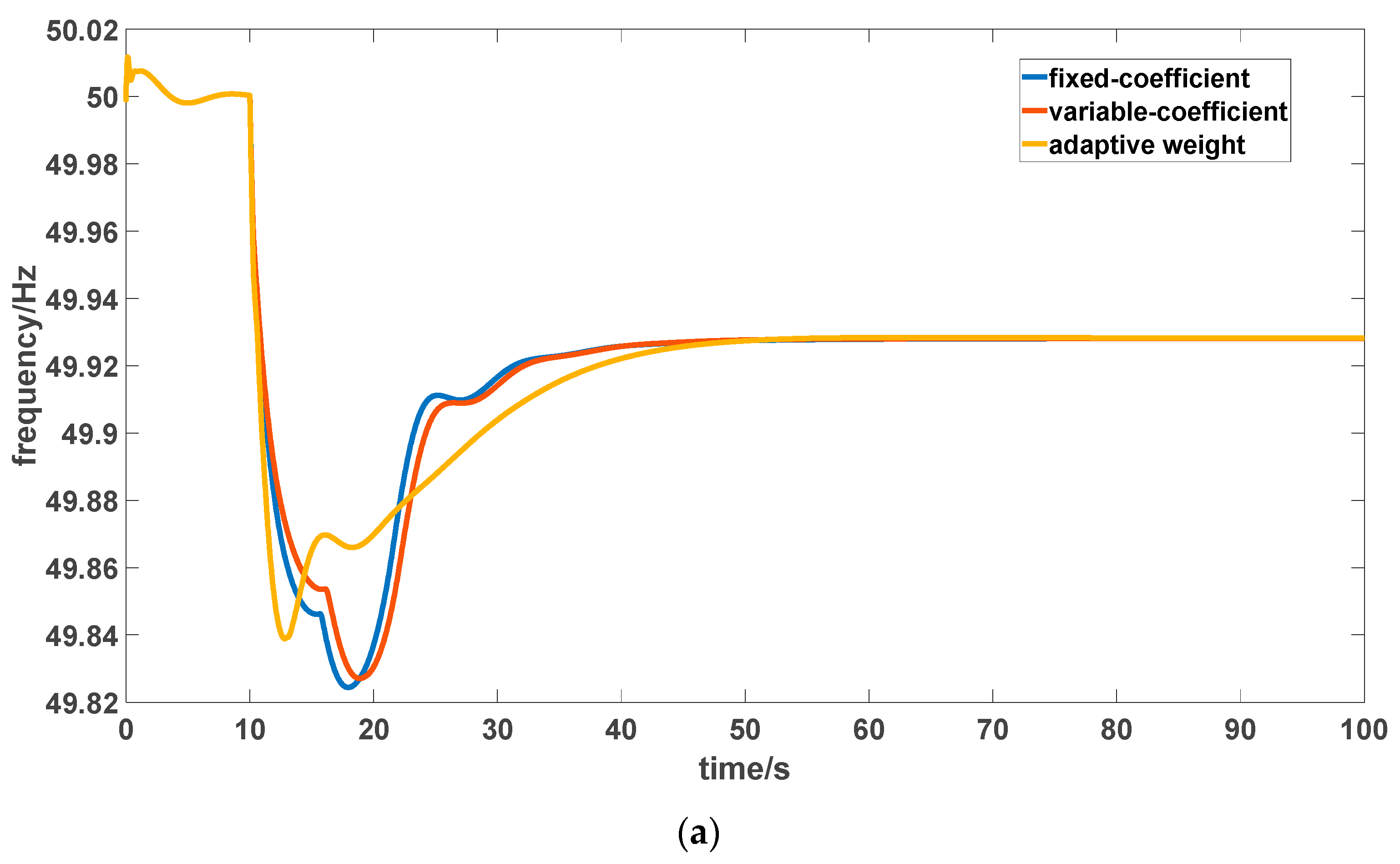
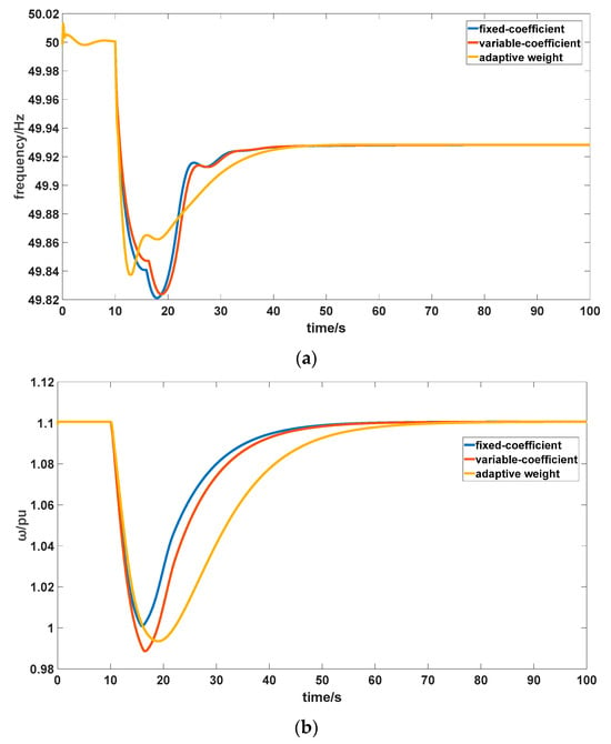
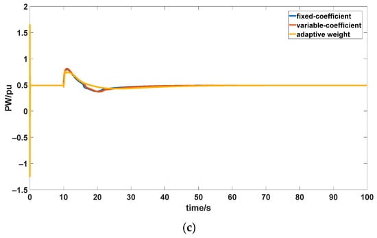
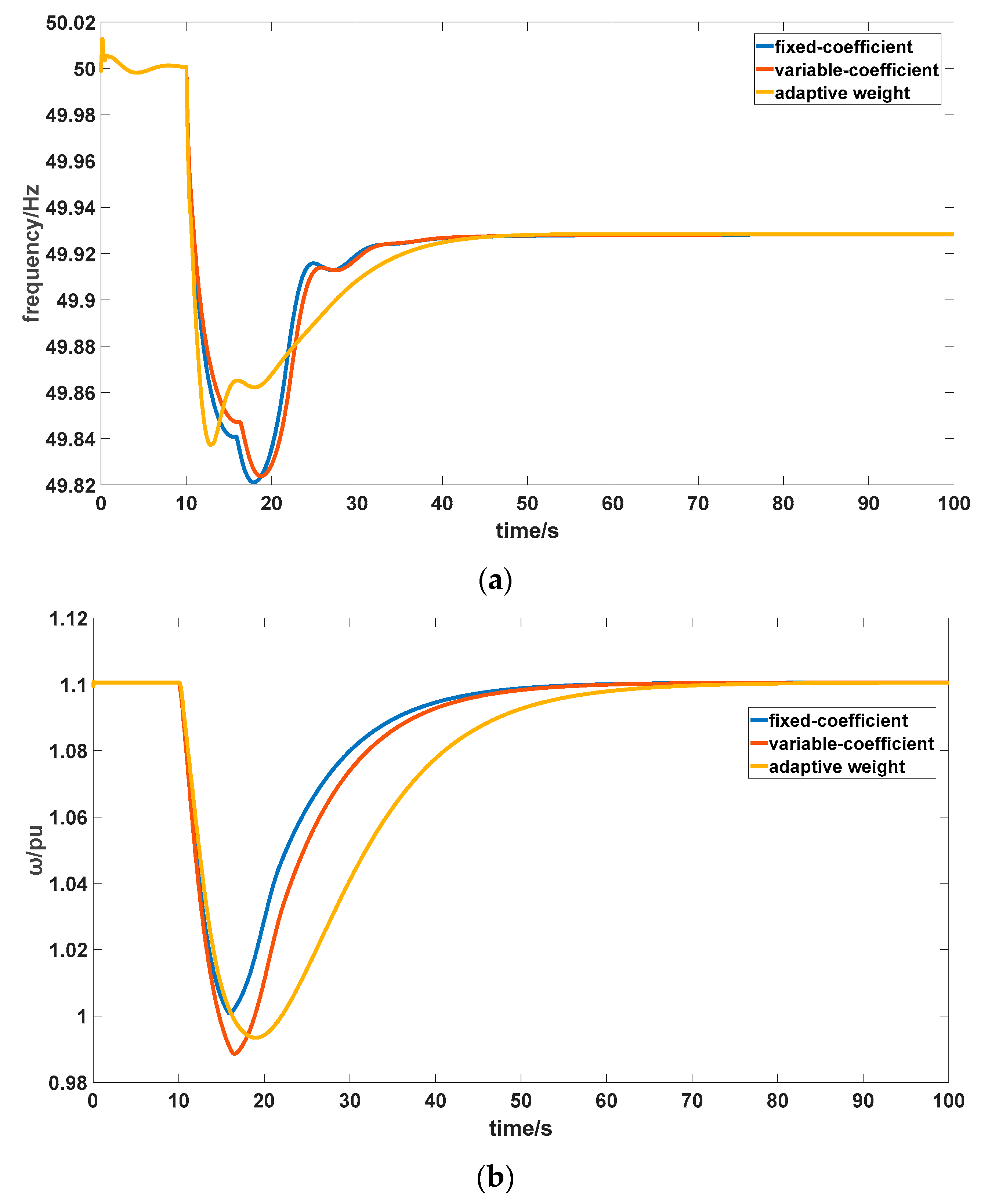
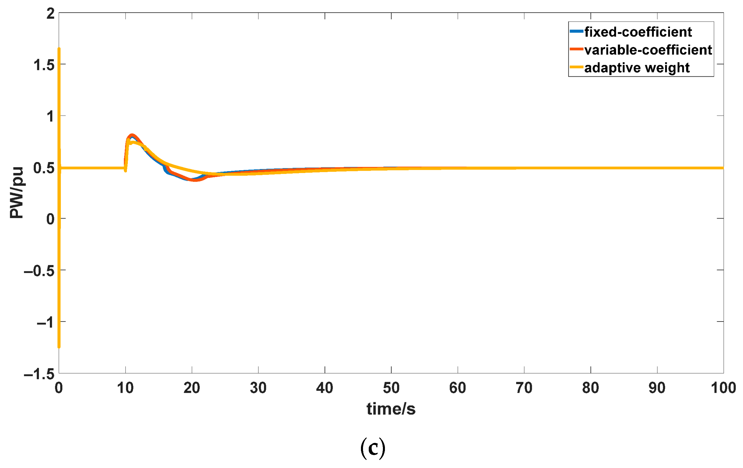
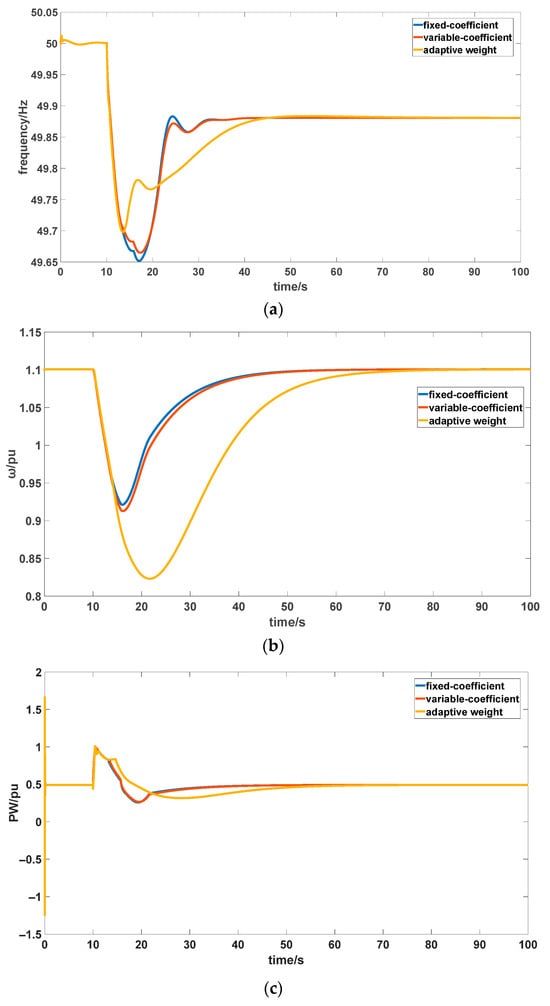
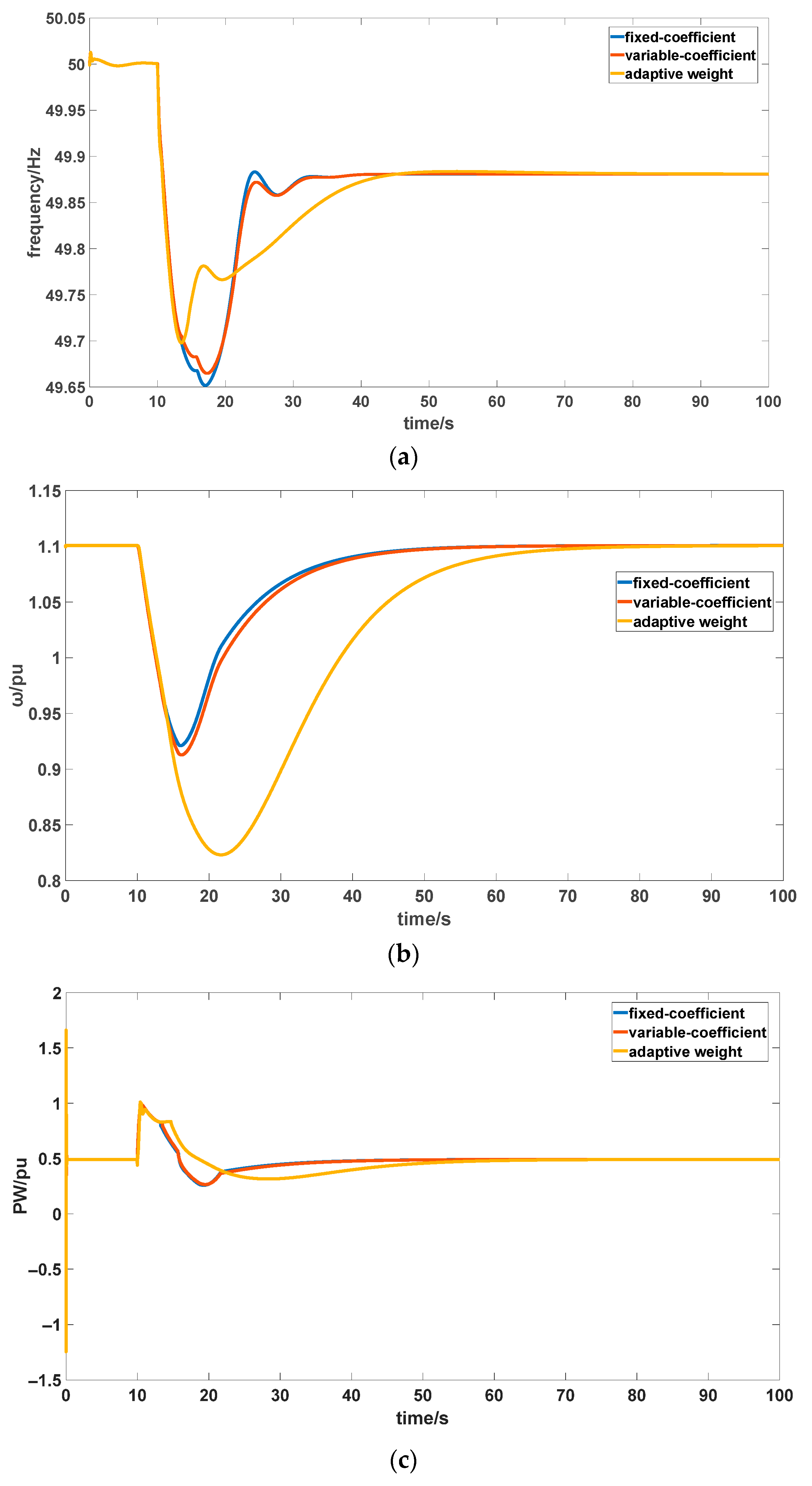
The frequency response curve of the DFIG-WT participating independently in grid frequency regulation at a wind speed of 9 m/s and a 30 MW step disturbance is shown in Figure 8. Figure 8a displays the power grid frequency. Results indicate that the frequency nadir under the rotor kinetic energy weight adaptive allocation strategy control is 49.84 Hz, representing an improvement of 0.032% over the 49.824 Hz achieved by fixed-coefficient control and 0.026% over the 49.827 Hz achieved by variable-coefficient control. The secondary frequency dip amplitude was only 0.0035 Hz, representing an improvement of roughly 84.1% over the 0.022 Hz achieved by fixed-coefficient control and an improvement of 86.5% over the 0.026 Hz achieved by variable-coefficient control. The time to reach the frequency nadir was 12.82 s, 28.6% shorter than the 17.95 s achieved with fixed-coefficient control and 32.1% shorter than the 18.88 s achieved with variable-coefficient control. This fully demonstrates that, without altering the overall frequency regulation capability of the DFIG-WT, significantly enhancing it can be achieved by adaptive weighting allocation between the droop output from the rotor’s kinetic energy and the inertia output.
Figure 8.
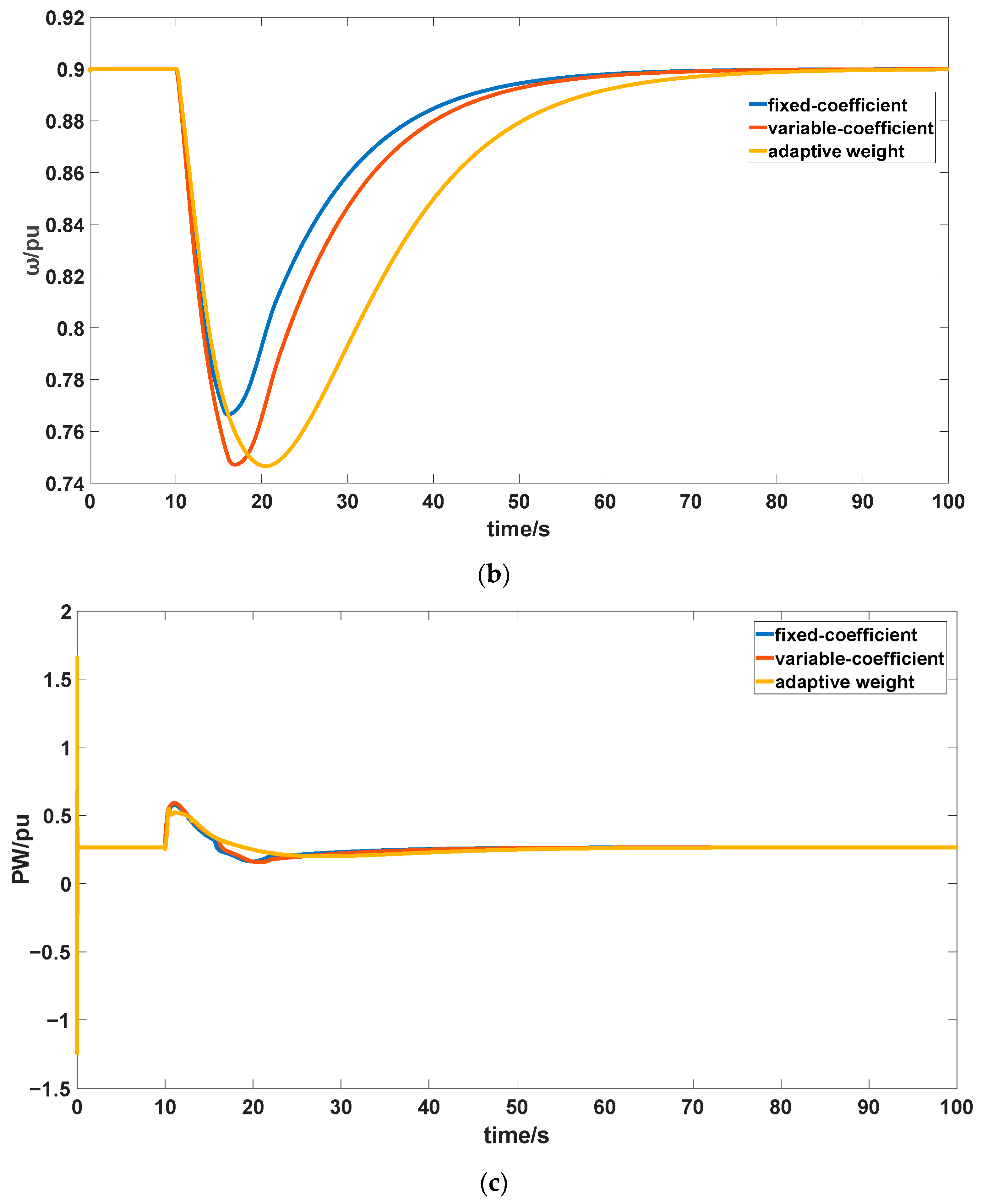
Response curve of DFIG-WT participating in frequency regulation under 9 m/s wind speed and 30 MW step disturbance: (a) power grid frequency; (b) DFIG-WT speed; (c) DFIG-WT power.
Figure 8b shows the rotational speed of the DFIG-WT. Results indicate that under the rotor kinetic energy-weighted adaptive allocation strategy, the minimum rotor speed reaches 0.7465 p.u., essentially on par with the 0.747 p.u. achieved by variable-coefficient control and representing a 2.55% reduction compared to the 0.766 p.u. under fixed-coefficient control. This demonstrates that the rotor kinetic energy weight adaptive allocation strategy enables more thorough and smoother extraction of rotor kinetic energy. The descent and recovery slopes are smoother, avoiding oscillations caused by the rapid release and cutoff of rotor kinetic energy in both fixed-coefficient and variable-coefficient wind turbine controls. During grid frequency recovery, a slow exit using a negative exponential function is adopted, sacrificing a small amount of recovery speed to achieve greater system damping and reduced oscillations.
Figure 8c illustrates the power output of the DFIG-WT. Results indicate that under the rotor kinetic energy weighting adaptive allocation strategy control, the peak power output reaches 0.546 p.u., representing a 5.37% reduction compared to the 0.577 p.u. achieved under fixed-coefficient control and a 7.46% decrease relative to the 0.59 p.u. under variable-coefficient control, with no higher instantaneous output peaks observed. In terms of output continuity and stability, the strategy demonstrates more enduring, effective support capability with significantly reduced output fluctuations. During the recovery phase, the DFIG-WT exhibits exceptionally smooth power restoration, effectively suppressing secondary frequency dip. This fully demonstrates that through rational power allocation, the strategy avoids instantaneous power impacts while enhancing system frequency regulation stability and continuity via sustained, stable output support and a smooth recovery process.
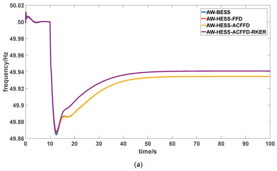
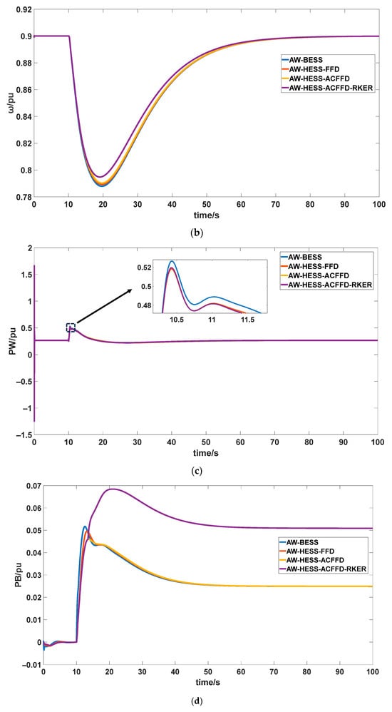
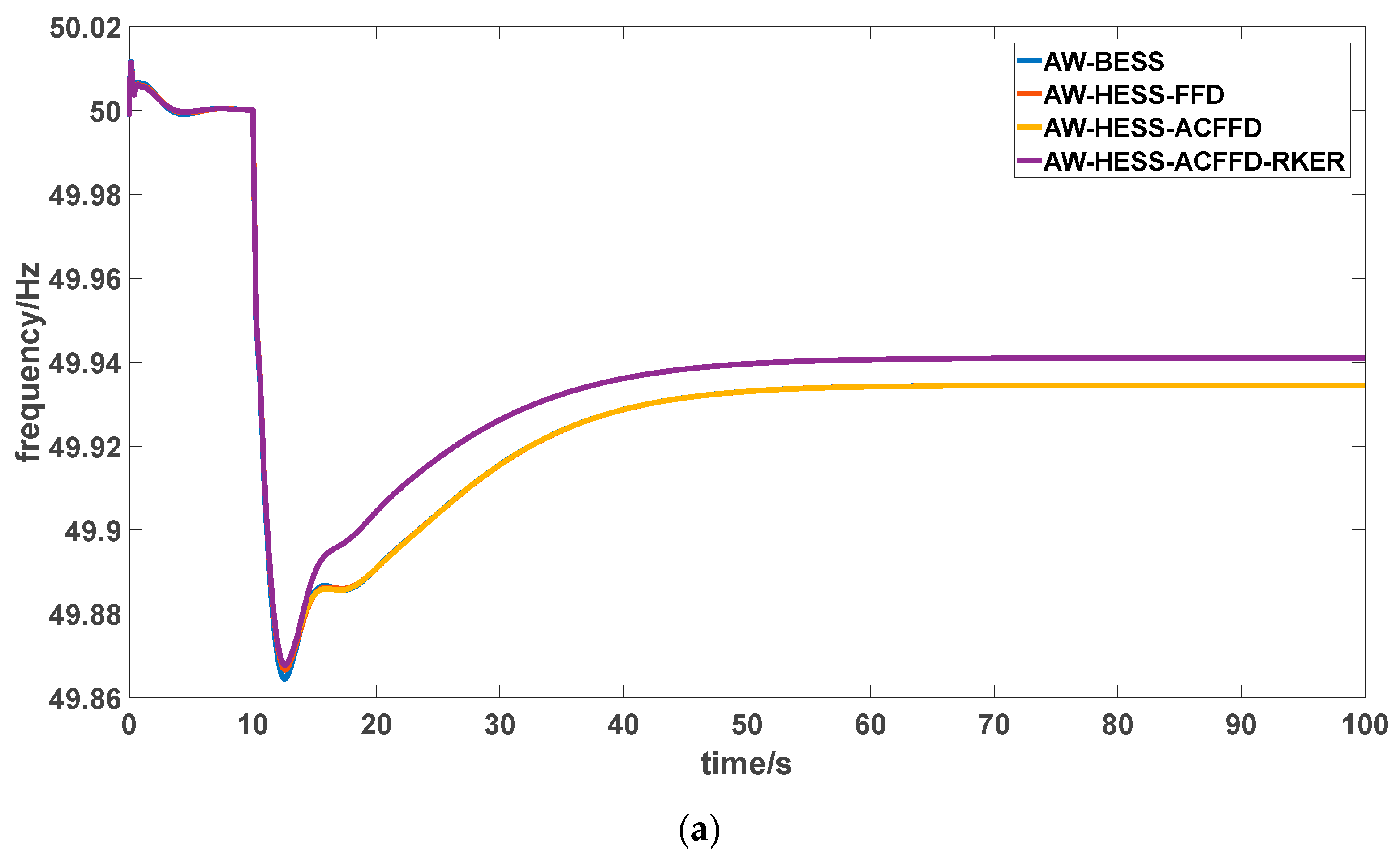
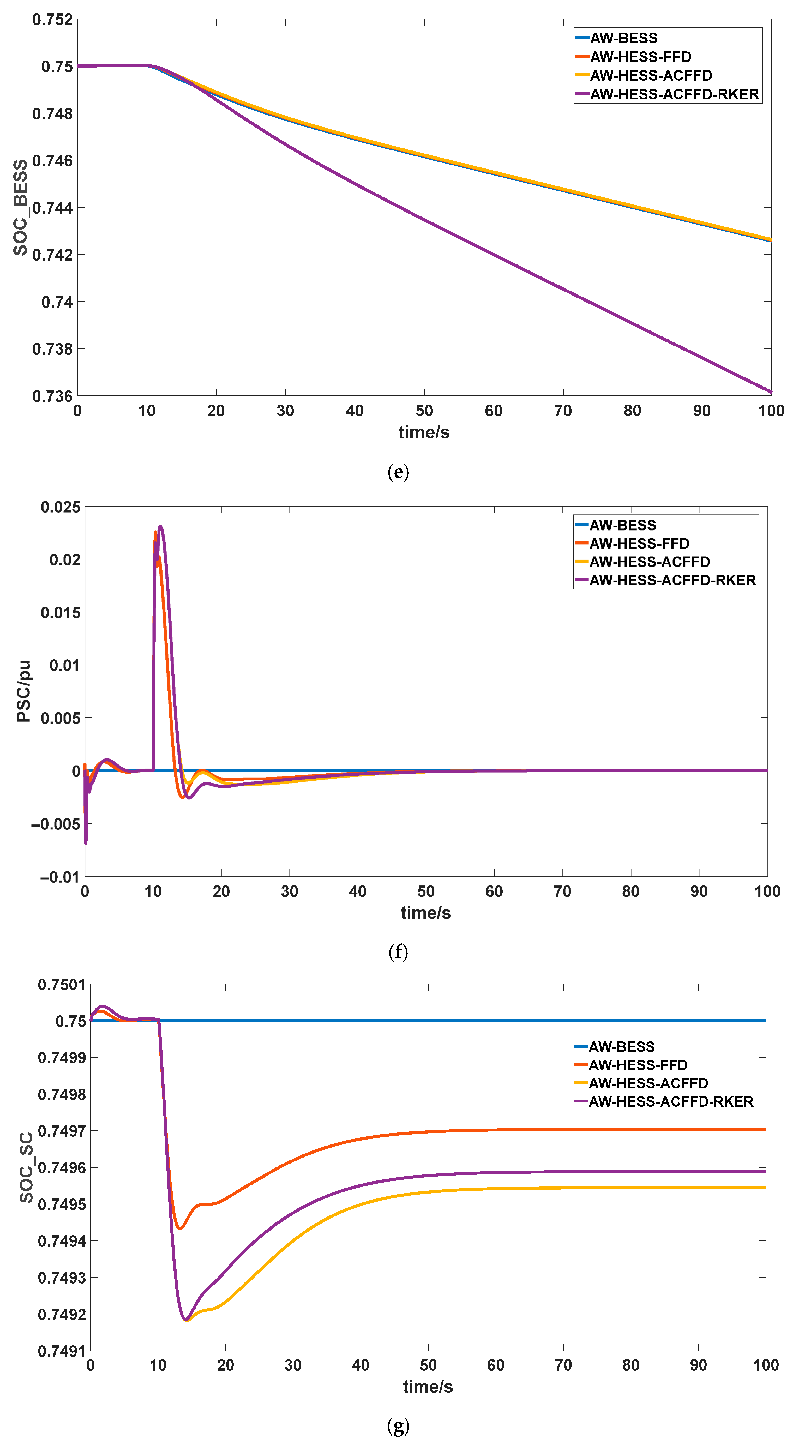
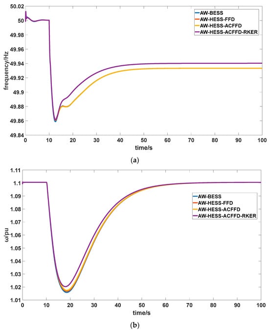
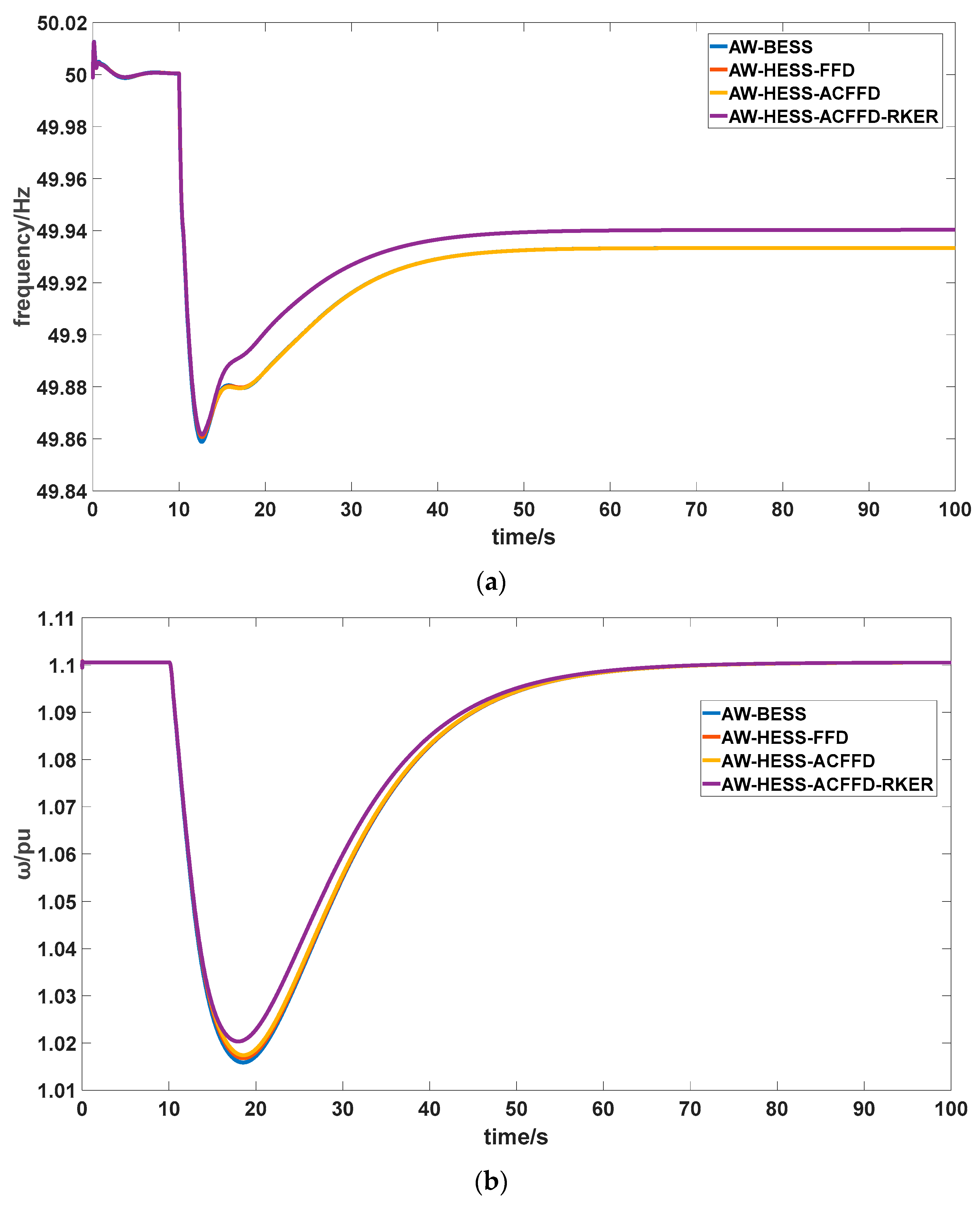
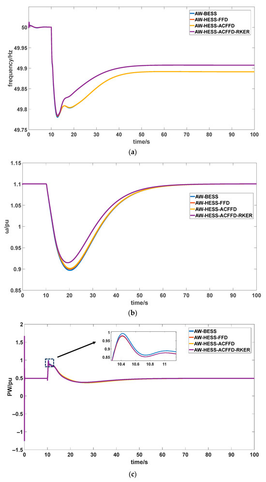
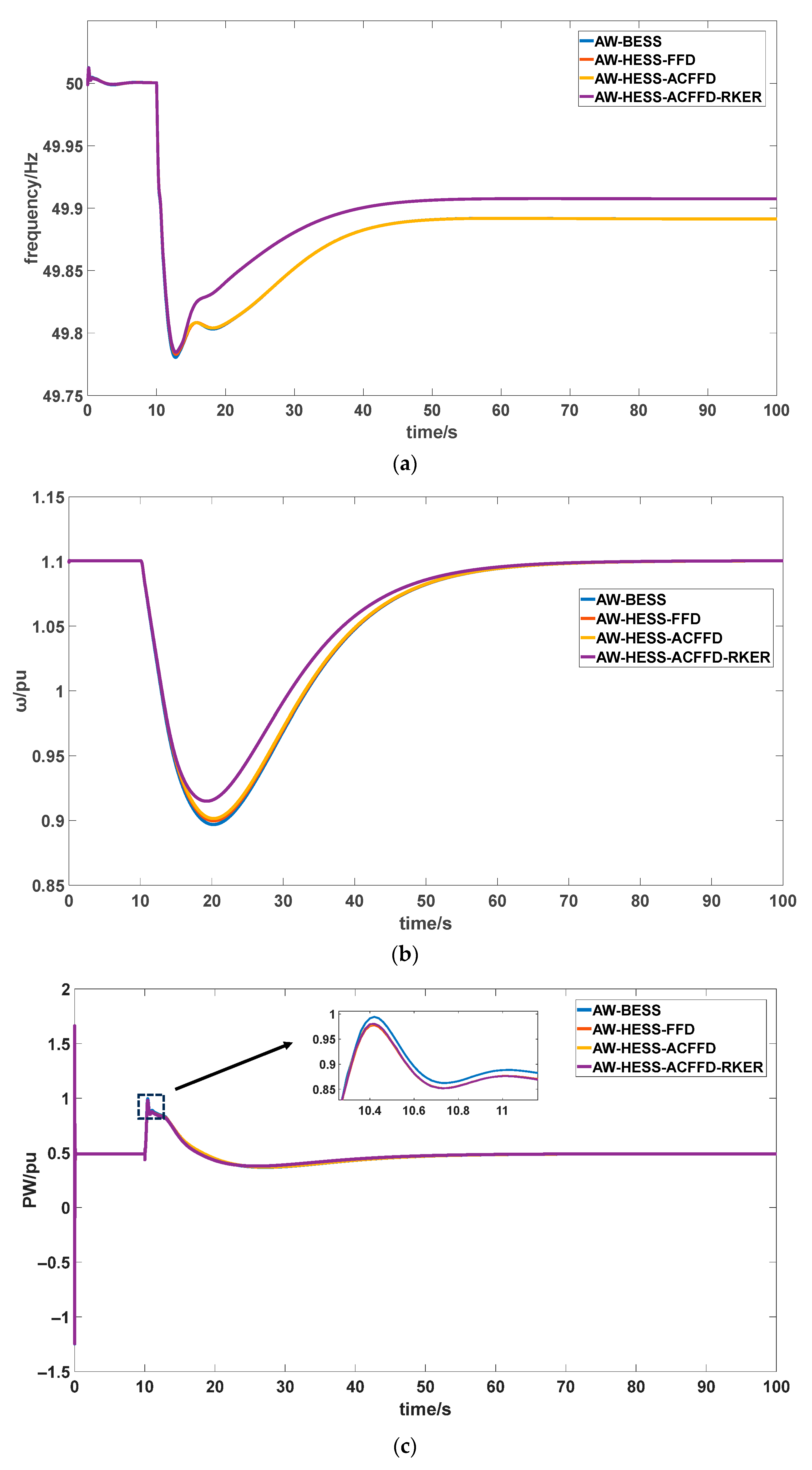
The frequency response curve for wind-storage coordinated participating in grid frequency regulation at a wind speed of 9 m/s and a 30 MW step disturbance is shown in Figure 9. Figure 9a displays the grid frequency. Results indicate that the frequency nadir achieved by the AW-HESS-ACFFD control strategy is 49.868 Hz, while the AW-BESS control strategy is 49.865 Hz and the AW-HESS-FFD control strategy is 49.867 Hz. The AW-HESS-ACFFD-RKER control strategy also achieved a frequency nadir of 49.867 Hz, matching the performance of the AW-HESS-ACFFD control strategy.
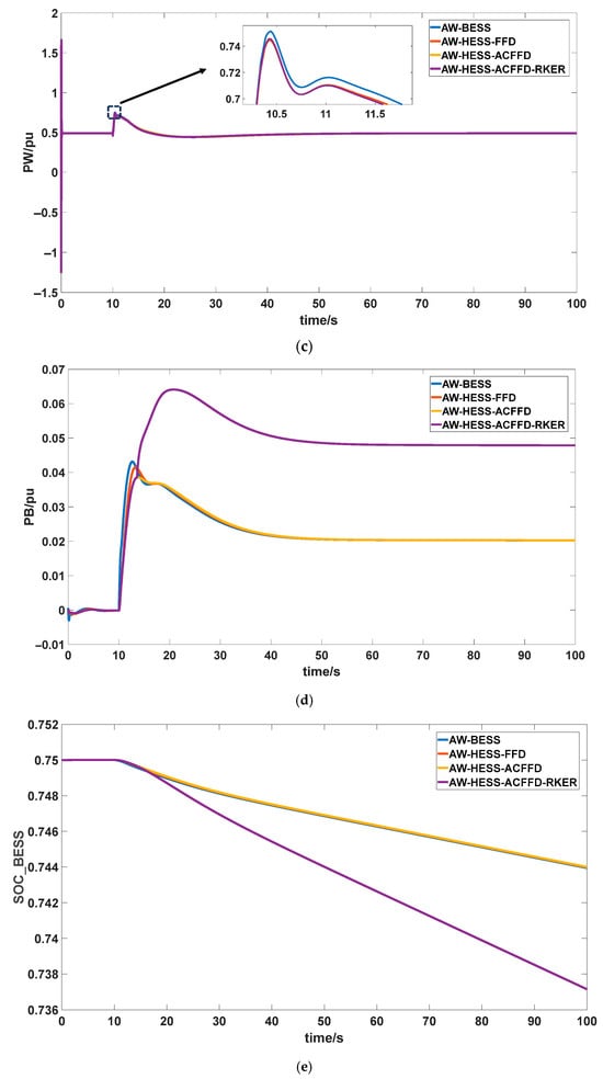
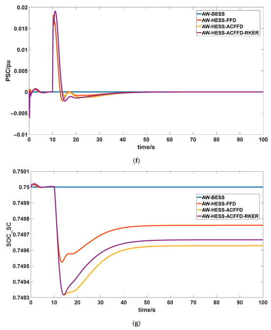
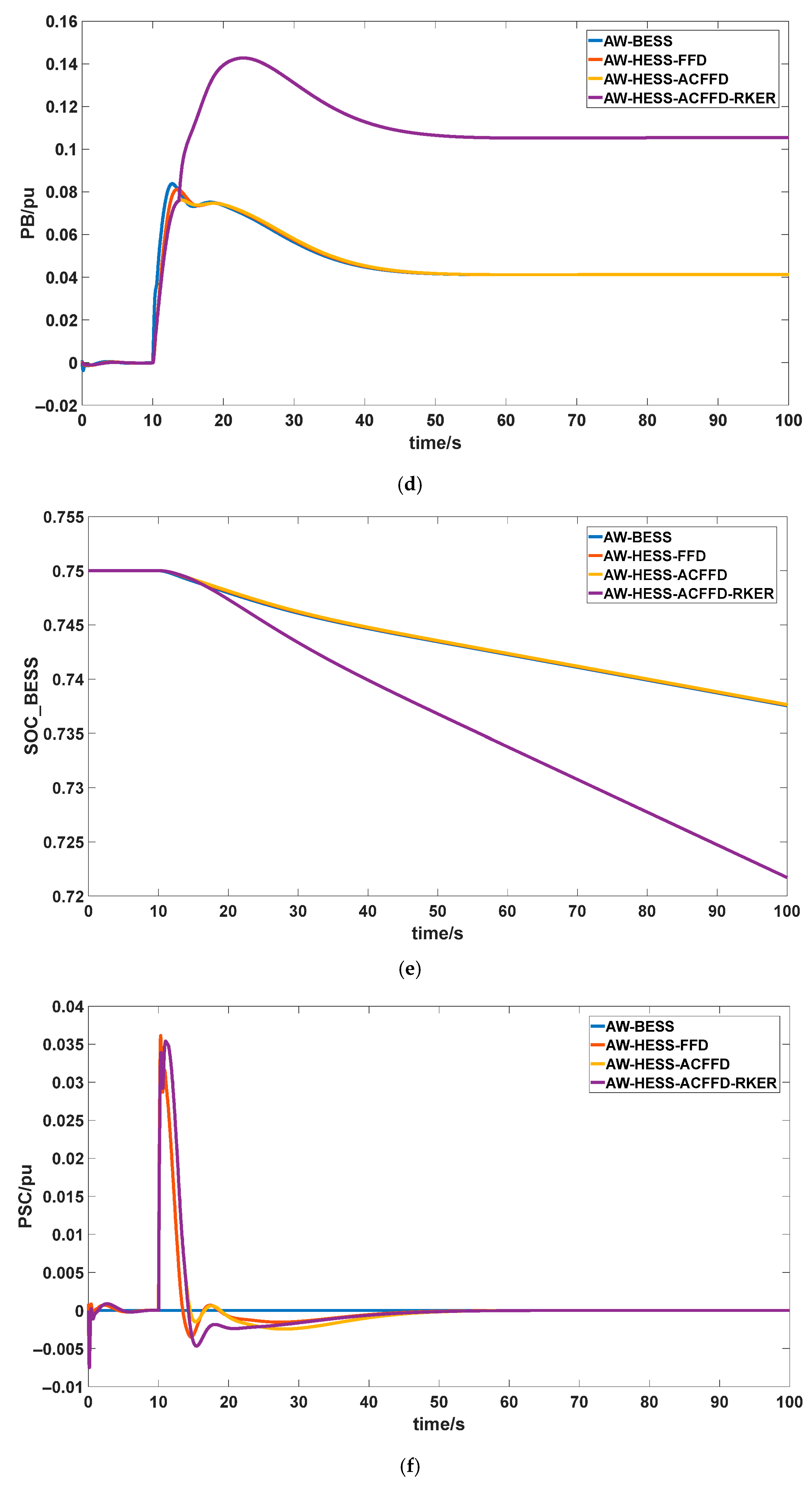
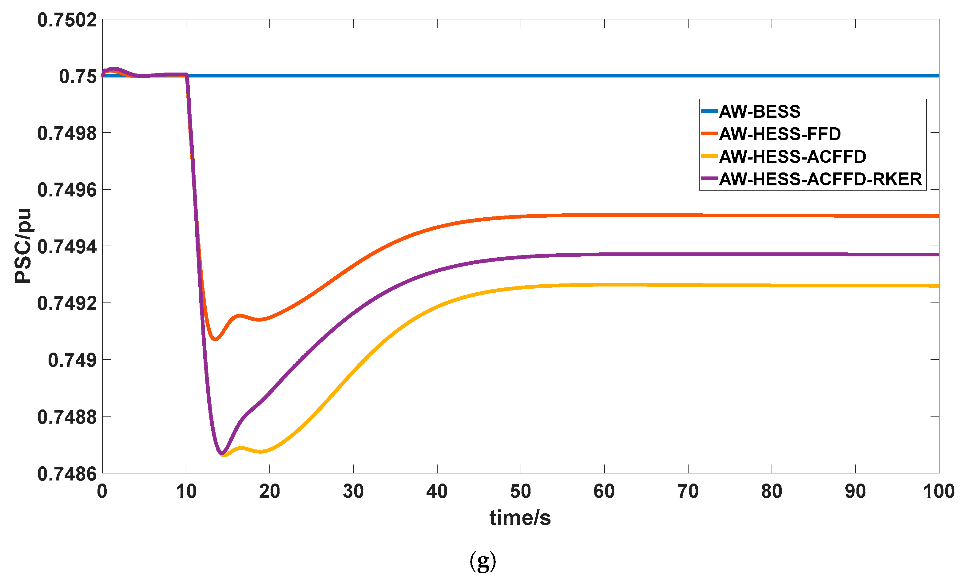
Figure 9.
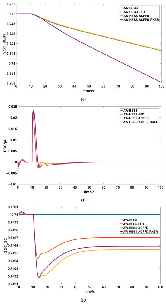
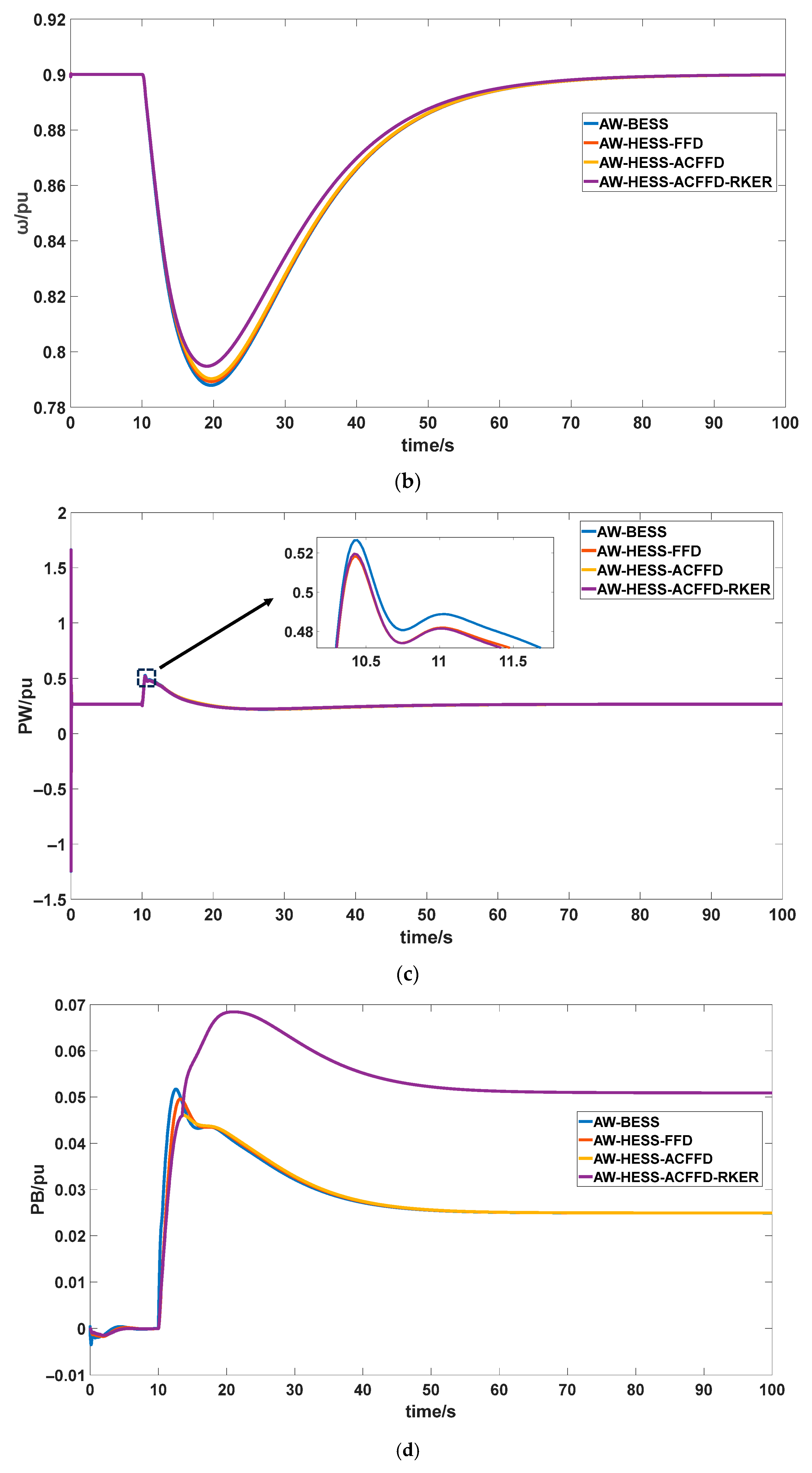
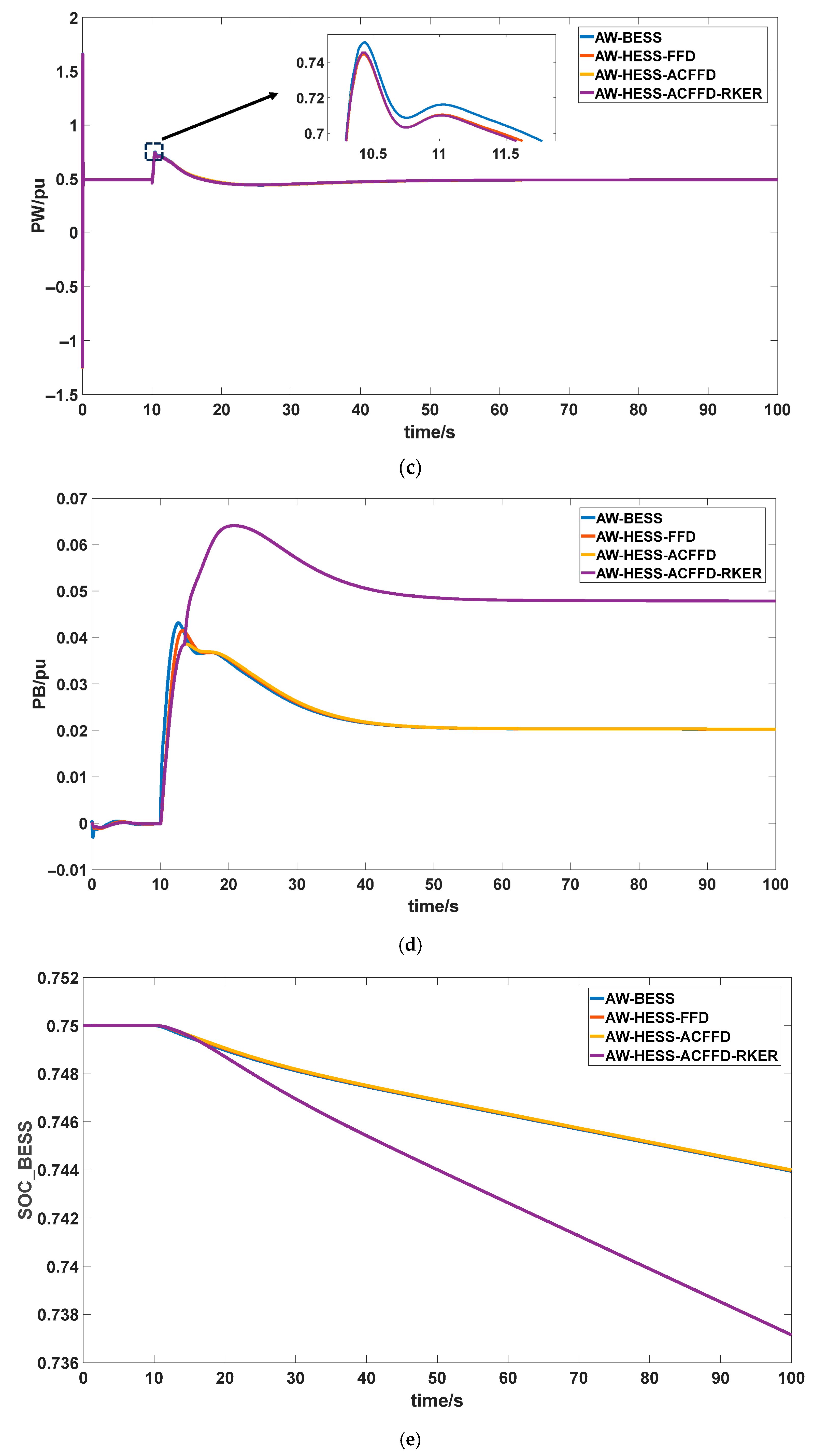
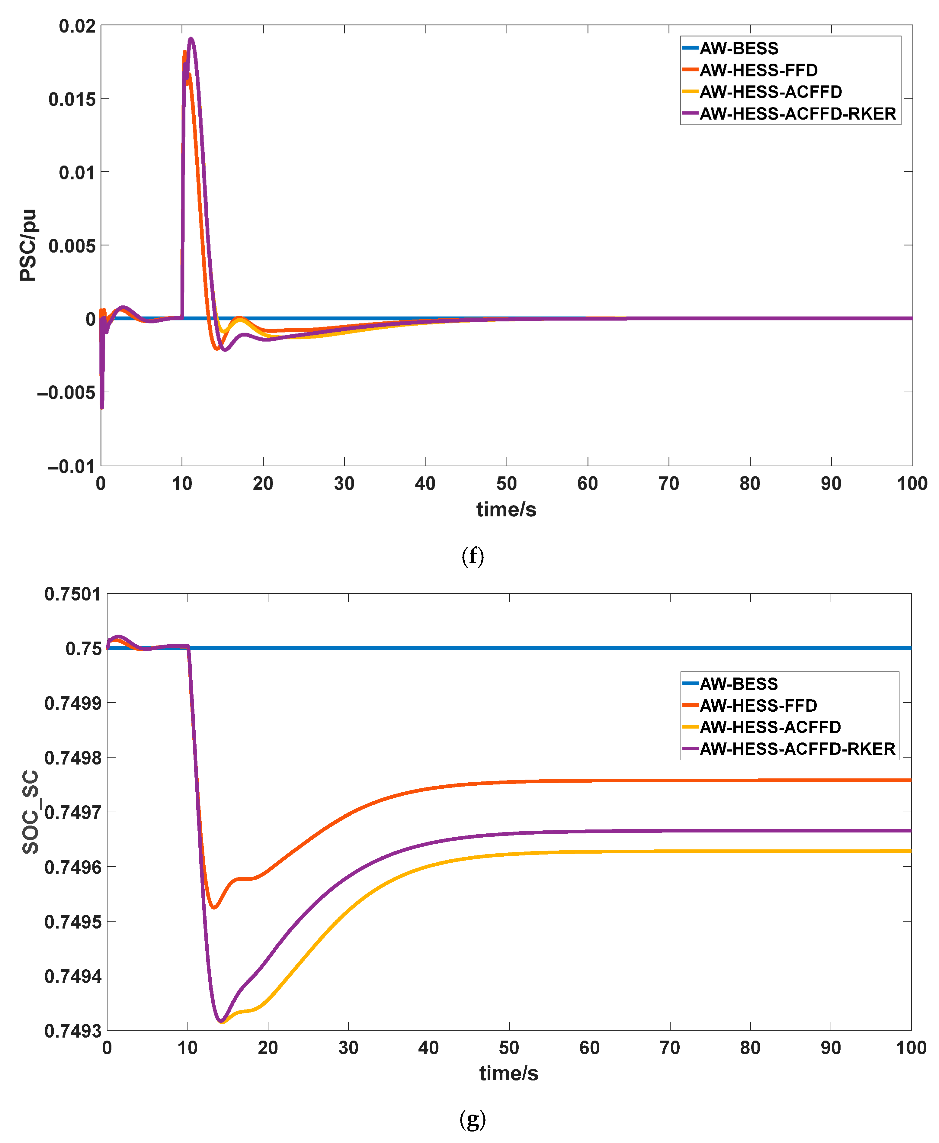
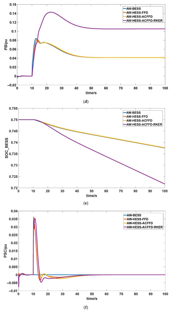
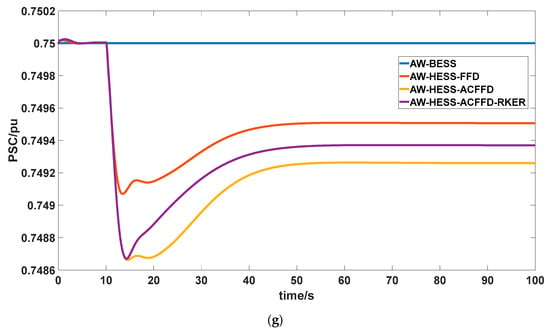
Response curve of wind-storage coordinated participating in frequency regulation under 9 m/s wind speed and 30 MW step disturbance: (a) power grid frequency; (b) DFIG-WT speed; (c) DFIG-WT power; (d) power of BESS; (e) SOC of BESS; (f) power of SC; (g) SOC of SC.
When DFIG-WT and HESS coordinated participate in frequency regulation, the secondary frequency dip in the power grid has been largely eliminated. The AW-HESS-ACFFD-RKER control achieves zero secondary frequency dip, eliminating the risk of frequency fluctuations. The steady-state frequency under AW-HESS-ACFFD control is 49.934 Hz. Under AW-HESS-ACFFD-RKER control, the steady-state frequency increases to 49.941 Hz, demonstrating better steady-state frequency performance. The HESS-ACFFD control strategy effectively elevates the frequency nadir point and suppresses secondary frequency dip through adaptive power allocation. Building upon this, the RKER strategy further eliminates secondary frequency dip while significantly enhancing steady-state frequency performance.
Figure 9b,c displays the rotor speed and power of the DFIG-WT. Results indicate that the minimum rotor speed under the AW-HESS-ACFFD control reaches 0.7905 p.u., representing a 0.32% improvement over the minimum of 0.788 p.u. achieved under AW-BESS control, and a 0.19% improvement over the minimum of 0.789 p.u. under AW-HESS-FFD control. The minimum rotor speed further increases to 0.795 p.u. under combined AW-HESS-ACFFD-RKER control. This represents a 0.57% improvement over the AW-HESS-ACFFD control, effectively reducing excessive kinetic energy release and facilitating rapid and stable speed recovery.
The peak output of all three HESS-related control strategies was lower than the 0.527 p.u. achieved by AW-BESS. Among these, the peak output of the AW-HESS-ACFFD control reached 0.519 p.u., representing a 1.52% reduction compared to the AW-BESS. Regarding minimum output, the AW-HESS-ACFFD control achieved a minimum of 0.222 p.u., representing a 6.22% improvement over the 0.209 p.u. minimum of the AW-BESS. The minimum output of the AW-HESS-ACFFD-RKER control reached 0.2238 p.u., representing a further 0.81% improvement. This demonstrates reduced output fluctuation and more stable, sustained support capability.
In summary, the ACFFD control strategy for mixed storage enables adaptive power allocation, thereby reducing DFIG-WT peak output while simultaneously increasing the minimum rotational speed and minimizing output fluctuations. Building on this foundation, the RKER strategy further optimizes the rotational-speed recovery characteristics of DFIG-WT.
Figure 9d–g, respectively, displays the power output and SOC of BESS, as well as the power output and SOC of SC. The results indicate that, compared to fixed-frequency division, the HESS-ACFFD control strategy can adaptively allocate high- and low-frequency signals to grid frequency fluctuations. During the initial phase of frequency fluctuations, this approach further enhances SC’s power output, thereby strengthening the grid’s dynamic response capability. Furthermore, utilizing BESS to assist DFIG-WT rotor kinetic energy recovery fundamentally resolves the secondary frequency dip. These control strategies fully leverage the SC’s rapid response and the BESS’s large capacity, more effectively utilizing the HESS’s advantages in suppressing frequency dips and providing steady-state support.
4.2. Case 2 Study: 11 m/s Wind Speed with 30 MW Step Disturbance
The response curve of the DFIG-WT participating independently in grid frequency regulation at a wind speed of 11 m/s and a 30 MW step disturbance is shown in Figure 10. The response curve of the wind-storage system coordinated participating in grid frequency regulation at a wind speed of 11 m/s and a 30 MW step disturbance is shown in Figure 11. Results indicate that at a wind speed of 11 m/s and a 30 MW step disturbance, the DFIG-WT operates at a higher rotational speed, providing greater rotor kinetic energy for frequency regulation. This enables deeper participation in frequency regulation during grid disturbances, resulting in both lower maximum frequency deviation and a lower steady-state frequency than in the 9 m/s wind speed scenario. Additionally, the output from the energy storage system decreases at a wind speed of 9 m/s. Under the HESS-ACFFD, the system frequency reached a minimum of 49.861 Hz at a wind speed of 11 m/s, with a steady-state frequency of 49.933 Hz. Nevertheless, the proposed control strategy demonstrated good applicability and effectiveness. Regarding system frequency, the rotor kinetic energy weighting allocation strategy still significantly improved the frequency nadir. For DFIG-WT output, the timely disengagement of the inertia component after the frequency nadir and the gradual disengagement of the droop component following a negative exponential law effectively suppresses secondary frequency dip, smoothing the disengagement of DFIG-WT frequency regulation and the recovery of rotor kinetic energy. In HESS control, the advantages of SC’s rapid response and BESS’s extensive storage capacity for stable support are effectively utilized, enhancing the grid’s dynamic frequency regulation capability and steady-state frequency.
Figure 10.
Response curve of DFIG-WT participating in frequency regulation under 11 m/s wind speed and 30 MW step disturbance: (a) power grid frequency; (b) DFIG-WT speed; (c) DFIG-WT power.
Figure 11.
Response curve of wind-storage coordinated participating in frequency regulation under 11 m/s wind speed and 30 MW step disturbance: (a) power grid frequency; (b) DFIG-WT speed; (c) DFIG-WT power; (d) power of BESS; (e) SOC of BESS; (f) power of SC; (g) SOC of SC.
4.3. Case 3 Study: 9 m/s Wind Speed with 50 MW Step Disturbance
The response curve of the DFIG-WT participating independently in grid frequency regulation at a wind speed of 11 m/s and a 50 MW step disturbance is shown in Figure 12. The response curve of the wind-storage system coordinated participating in grid frequency regulation at a wind speed of 11 m/s and a 50 MW step disturbance is shown in Figure 13. Results indicate that under the more severe disturbance condition of 11 m/s wind speed and 50 MW step load, the proposed wind-storage coordinated primary frequency regulation control strategy remains effective: On the DFIG-WT side, adaptive weight-based integrated inertia control enables greater release of rotor kinetic energy during disturbances to elevate the system’s frequency nadir. After reaching the frequency nadir, it smoothly exits frequency regulation, maintaining controllable speed reduction and recovery while preventing abrupt energy absorption shocks. On the HESS side, adaptive complementary filtering frequency division prioritizes SC for high-frequency transient power absorption to suppress oscillations, while BESS provides sustained energy support and assists in recovering rotor kinetic energy during the restoration phase, effectively mitigating the risk of secondary frequency dips within the recovery window. In summary, even under severe frequency events like the 50 MW scenario, the proposed strategy achieves rapid power support, smooth DFIG-WT withdrawal from frequency regulation, and closed-loop coordination with BESS-assisted rotor kinetic energy recovery, demonstrating robust performance and engineering feasibility.
Figure 12.
Response curve of DFIG-WT participating in frequency regulation under 11 m/s wind speed and 50 MW step disturbance: (a) power grid frequency; (b) DFIG-WT speed; (c) DFIG-WT power.
Figure 13.
Response curve of wind-storage coordinated participating in frequency regulation under 11 m/s wind speed and 50 MW step disturbance: (a) power grid frequency; (b) DFIG-WT speed; (c) DFIG-WT power; (d) power of BESS; (e) SOC of BESS; (f) power of SC; (g) SOC of SC.
4.4. Case 4 Study: 9 m/s Wind Speed with Continuous Disturbance
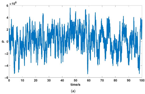
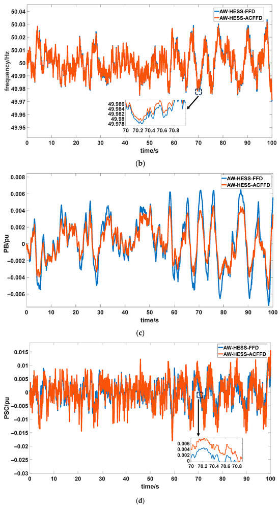
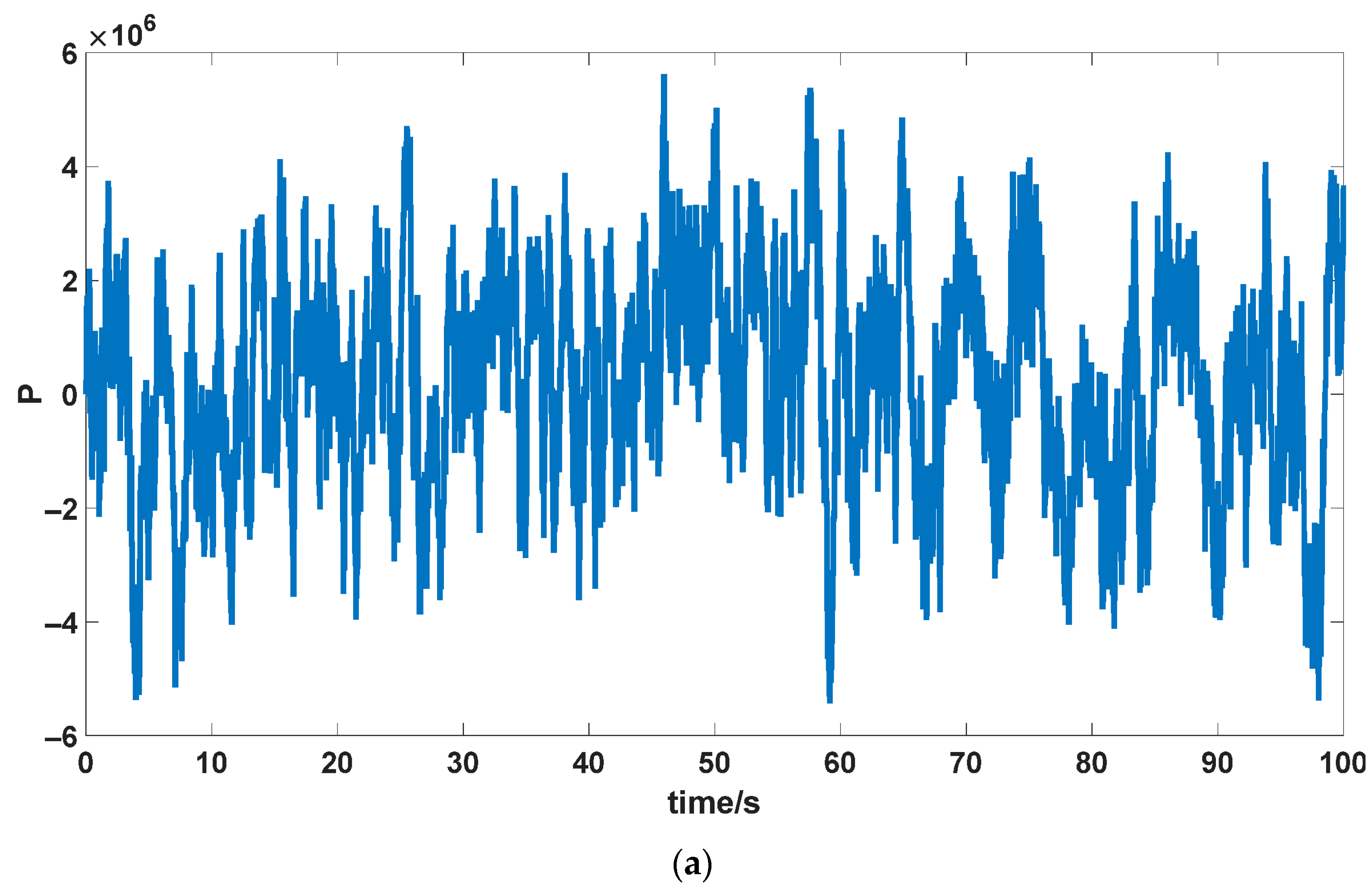
To validate the effectiveness of the HESS-ACFFD control strategy, under conditions of 9 m/s wind speed and wind-storage coordinated frequency regulation employing rotor kinetic energy weighting, continuous load disturbances were applied that fluctuated between −6 MW and +6 MW. The response curve of the wind-storage coordinated frequency regulation system under a constant load disturbance at a wind speed of 9 m/s is shown in Figure 14. Figure 14a displays the waveform of the continuous load disturbance.
Figure 14.
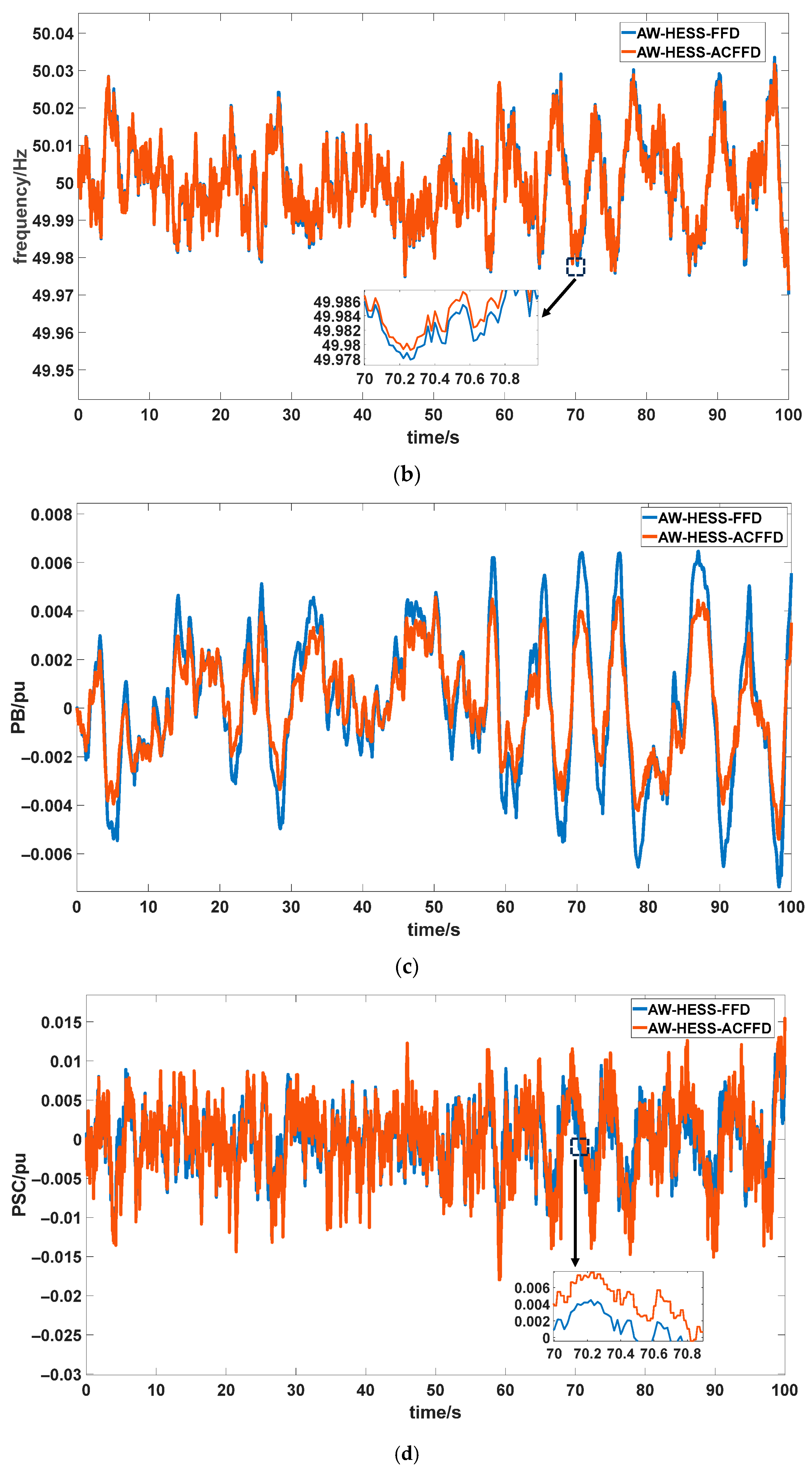
Wind-storage coordinated frequency regulation response curve under continuous load disturbance at 9 m/s wind speed: (a) power of continuous load disturbances; (b) power grid frequency; (c) power of BESS; (d) power of SC.
Figure 14b–d illustrates the grid frequency, power of BESS, and power of SC under continuous disturbances. Results indicate that HESS exhibits smaller grid frequency fluctuation amplitudes when employing ACFFD control. Compared to the fixed-frequency division strategy, the ACFFD strategy yields SC power waveforms with higher amplitudes and more active responses. SC exhibits faster tracking of frequency fluctuations and shoulders a greater share of rapid power regulation tasks. Correspondingly, the amplitude of power variations in BESS is significantly reduced. This leads to fewer charge/discharge cycles and a lower depth of discharge for BESS, thereby extending its lifespan. In summary, ACFFD control not only fully leverages the SC’s advantages of rapid response and long cycle life but also balances the longevity benefits of BESS during frequency fluctuation suppression. This approach enhances the overall dynamic performance of wind-storage combined primary frequency regulation.
5. Conclusions
This paper addresses the secondary frequency dip caused by DFIG-WT participating in primary frequency regulation and the issue of high- and low-frequency signal allocation in grid frequency regulation involving HESS. It proposes a wind-storage coordinated primary frequency regulation strategy incorporating rotor kinetic energy recovery. Experimental results demonstrate the following advantages of this control strategy: By fully utilizing rotor kinetic energy with weighted control during rapid frequency decline phases, it enhances equivalent inertia and active power support, significantly raising the grid frequency nadir. Upon reaching the nadir, inertia output is immediately withdrawn while drooping output is slowly retracted with a negative exponent, enhancing control stability and reducing frequency fluctuations caused by turbine withdrawal. Compared to traditional fixed-coefficient and variable-coefficient schemes, this strategy exhibits controlled reduction and smooth recovery of rotor kinetic energy on the DFIG-WT side, while significantly reducing frequency oscillations and shortening recovery time on the grid side.
In HESS control, the system adaptively divides frequency components based on the intensity of grid frequency disturbances. This enables SC to rapidly absorb the steepest frequency components, while BESS handles sustained components and assists DFIG-WT rotor kinetic energy recovery during frequency restoration. This approach not only completely resolves secondary frequency dip but also flexibly leverages HESS’s advantages, enhancing the power system’s dynamic response and steady-state recovery capabilities.
Practical deployment may be affected by mechanical and converter constraints of DFIG-WTs, power/energy limits of HESS, and measurement/communication delays. These non-idealities may cause saturation, reduced tracking accuracy, and imperfect nadir-based switching. Therefore, engineering implementation should include standard limiting/protection and delay-aware tuning, while storage sizing should be based on representative disturbance scenarios. This strategy is scalable because it is based on local frequency measurement and unit-level power modulation, enabling straightforward extension from single units to plant aggregation and ultimately large-scale systems. It acts at the primary frequency-control timescale and complements existing governor and secondary frequency controls, while dead-zone and limiting protections support grid-code-compliant integration.
Author Contributions
Methodology, X.Z.; software, H.Z.; validation, P.Z.; formal analysis, H.H.; writing—original draft, X.Z.; writing—review and editing, W.D. and Y.S.; visualization, G.S.; supervision, P.Z., Z.L. and Y.S.; project administration, Z.L. and Y.S. All authors have read and agreed to the published version of the manuscript.
Funding
This work was supported by the Science and Technology Project of State Grid Inner Mongolia Eastern Electric Power Co., Ltd. (52660024000G). We gratefully acknowledge this support.
Data Availability Statement
Due to privacy concerns, the data is not publicly accessible.
Conflicts of Interest
Authors Xuenan Zhao, Hao Hu, Guozheng Shang, Pengyu Zhao, and Wenjing Dong were employed by the company “State Grid Inner Mongolia Eastern Electric Power Co., Ltd.”. The remaining authors declare that the research was conducted in the absence of any commercial or financial relationships that could be construed as a potential conflict of interest. The authors declare that this study received funding from the State Grid Inner Mongolia Eastern Electric Power Co., Ltd. The funder was not involved in the study design, collection, analysis, interpretation of data, the writing of this article, or the decision to submit it for publication.
Abbreviations
The following abbreviations are used in this manuscript:
| Abbreviation | Description |
| DFIG | Doubly fed induction generator |
| DFIG-WT | Doubly fed induction generator-based wind turbine |
| HESS | Hybrid energy storage system |
| SOC | State of charge |
| BESS | Battery energy storage system |
| SC | Supercapacitor |
| ROCOF | Rate of change of frequency |
| MPPT | Maximum power point tracking |
| AW-BESS | Adaptive weight control combined with a battery energy storage system |
| AW-HESS-FFD | Adaptive weight control combined with a hybrid energy storage system employing fixed frequency division |
| AW-HESS-ACFFD | Adaptive weight control combined with a hybrid energy storage system employing adaptive complementary filtering frequency division |
| AW-HESS-ACFFD-RKER | Adaptive weight control combined with a hybrid energy storage system employing adaptive complementary filtering frequency division, with BESS assisting wind turbine rotor kinetic energy recovery |
| Symbol | Description |
| Mechanical power of DFIG-WT | |
| Power coefficient | |
| Hybrid energy storage system | |
| Tip speed ratio | |
| Pitch angle | |
| Wind speed | |
| Rotational speed of the rotor | |
| MPPT power of the DFIG-WT | |
| proportional coefficient of the MPPT | |
| Rotor energy | |
| Equivalent rotational inertia of the DFIG-WT | |
| Additional power | |
| Inertia control coefficient of DFIG-WT | |
| Droop control coefficient of DFIG-WT | |
| Frequency deviation | |
| Reference power of the DFIG-WT | |
| Normalized value of ROCOF | |
| Scaling constant that normalizes ROCOF | |
| Normalized value of | |
| Scaling constant that normalizes | |
| Inertia weighting factor | |
| Droop weighting factor | |
| Baseline weighting factor without disturbance | |
| Inertia output control weighting factor | |
| Droop output control weighting factor | |
| Inertia adaptation factor | |
| Droop adaptation factor | |
| Inertia scaling reference | |
| Inertia scaling control factors | |
| Droop scaling control factors | |
| Droop scaling reference | |
| Time corresponding to the frequency nadir | |
| Cutoff frequency of the filter | |
| Reference power of the energy storage system | |
| Inertia control coefficient of the energy storage system | |
| Droop control coefficient of the energy storage system | |
| Droop control coefficient during discharging | |
| Droop control coefficient during charging | |
| BESS discharge coefficient for restoring rotor kinetic energy in DFIG-WT | |
| Filter with a short time constant | |
| Filter with a long time constant | |
| Cross-hybridization weight of filters | |
| High-frequency signal | |
| Low-frequency signal | |
| Transfer function of a low-frequency signal | |
| Transfer function of a high-frequency signal | |
| Transfer function of synchronous units | |
| Transfer Function of DFIG-WT | |
| Transfer Function of BESS | |
| Transfer Function of SC | |
| Time constant of synchronous units | |
| Time constant of BESS | |
| Time constant of SC | |
| Time constant of the filter | |
| Load-induced disturbance | |
| Angular frequency of the lowest frequency band | |
| Magnitude of the low-frequency signal at | |
| Magnitude of the high-frequency signal at | |
| Magnitudes of BESS through the first-order link | |
| Magnitudes of SC through the first-order link | |
| Equivalent droop magnitude of the synchronous units at | |
| Equivalent inertia gain | |
| Equivalent inertia gain of DFIG-WT | |
| Equivalent inertia gain of BESS | |
| Equivalent inertia gain of SC | |
| Equivalent droop gain | |
| Equivalent droop gain of DFIG-WT | |
| Equivalent droop gain of BESS | |
| Equivalent droop gain of SC | |
| Equivalent first-order time constant | |
| The proportion of droop components borne by the BESS | |
| The proportion of droop components borne by the SC | |
| Effective inertia | |
| First-order coefficient of the second-order equivalent denominator | |
| The zero-order coefficient of the second-order equivalent denominator | |
| Natural frequency | |
| Damping ratio | |
| Damped oscillation angular frequency | |
| Amplitude corresponding to the single zero point | |
| Phase angle corresponding to the single zero point | |
| Steady-state frequency deviation | |
| Maximum frequency deviation |
Appendix A
The three-machine nine-node model is a standard test case widely used in power system research. In this schematic diagram, B1–B9 represent buses, G1 and G2 represent synchronous generators, T1–T3 represent transformers, Load1–Load4 represent fixed loads, and Load5 represents the load causing disturbances.
Figure A1.
Three-machine nine-node model structure diagram.
References
- Cheng, X.; Ye, K.; Min Du, A.; Bao, Z.; Chlomou, G. Dual Carbon Goals and Renewable Energy Innovations. Res. Int. Bus. Financ. 2024, 70, 102406. [Google Scholar] [CrossRef] [Scilit]
- Jia, X.; Zhang, Y.; Tan, R.R.; Li, Z.; Wang, S.; Wang, F.; Fang, K. Multi-Objective Energy Planning for China’s Dual Carbon Goals. Sustain. Prod. Consum. 2022, 34, 552–564. [Google Scholar] [CrossRef] [Scilit]
- Shi, C.; Yu, M. Flexible Solid-State Lithium-Sulfur Batteries Based on Structural Designs. Energy Storage Mater. 2023, 57, 429–459. [Google Scholar] [CrossRef] [Scilit]
- Peng, W.; Lu, S.; Lu, W. Green Financing for the Establishment of Renewable Resources under Carbon Emission Regulation. Renew. Energy 2022, 199, 1210–1225. [Google Scholar] [CrossRef] [Scilit]
- Beyza, J.; Yusta, J.M. The Effects of the High Penetration of Renewable Energies on the Reliability and Vulnerability of Interconnected Electric Power Systems. Reliab. Eng. Syst. Saf. 2021, 215, 107881. [Google Scholar] [CrossRef] [Scilit]
- Mararakanye, N.; Bekker, B. Renewable Energy Integration Impacts within the Context of Generator Type, Penetration Level and Grid Characteristics. Renew. Sustain. Energy Rev. 2019, 108, 441–451. [Google Scholar] [CrossRef] [Scilit]
- Adetokun, B.B.; Muriithi, C.M.; Ojo, J.O. Voltage Stability Assessment and Enhancement of Power Grid with Increasing Wind Energy Penetration. Int. J. Electr. Power Energy Syst. 2020, 120, 105988. [Google Scholar] [CrossRef] [Scilit]
- Fernández-Bustamante, P.; Barambones, O.; Calvo, I.; Napole, C.; Derbeli, M. Provision of Frequency Response from Wind Farms: A Review. Energies 2021, 14, 6689. [Google Scholar] [CrossRef] [Scilit]
- Alqahtani, S.; Shaher, A.; Garada, A.; Cipcigan, L. Impact of the High Penetration of Renewable Energy Sources on the Frequency Stability of the Saudi Grid. Electronics 2023, 12, 1470. [Google Scholar] [CrossRef] [Scilit]
- Farghaly, M.B.; Abdelghany, E.S. Study the effect of trailing edge flap deflection on horizontal axis wind turbine performance using computational investigation. Int. J. Renew. Energy Res. 2022, 12, 1942–1953. [Google Scholar] [CrossRef] [Scilit]
- Yang, D.; Jin, Z.; Zheng, T.; Jin, E. An Adaptive Droop Control Strategy with Smooth Rotor Speed Recovery Capability for Type III Wind Turbine Generators. Int. J. Electr. Power Energy Syst. 2022, 135, 107532. [Google Scholar] [CrossRef] [Scilit]
- Boyle, J.; Littler, T.; Muyeen, S.M.; Foley, A.M. An Alternative Frequency-Droop Scheme for Wind Turbines That Provide Primary Frequency Regulation via Rotor Speed Control. Int. J. Electr. Power Energy Syst. 2021, 133, 107219. [Google Scholar] [CrossRef] [Scilit]
- He, D.; Li, Y.; Cao, C.; Fan, Y.; Wang, F.; Zhang, Y.; Cheng, C. Speed-Adaptive Droop Control for Doubly Fed Induction Generator-Based Gravity Energy Storage System. Energies 2025, 18, 5671. [Google Scholar] [CrossRef] [Scilit]
- Liu, Z.; Yang, P.; Zhang, P.; Lin, X.; Wei, J.; Li, N. Optimization of Fuzzy Control Parameters for Wind Farms and Battery Energy Storage Systems Based on an Enhanced Artificial Bee Colony Algorithm under Multi-Source Sensor Data. Sensors 2024, 24, 5115. [Google Scholar] [CrossRef] [Scilit]
- Kheshti, M.; Lin, S.; Zhao, X.; Ding, L.; Yin, M.; Terzija, V. Gaussian Distribution-Based Inertial Control of Wind Turbine Generators for Fast Frequency Response in Low Inertia Systems. IEEE Trans. Sustain. Energy 2022, 13, 1641–1653. [Google Scholar] [CrossRef] [Scilit]
- Ding, X.; Zhang, Y. Adaptive Virtual Inertia in Doubly Fed Induction Generators for Enhanced Frequency Regulation. IEEE Access 2025, 13, 55616–55626. [Google Scholar] [CrossRef] [Scilit]
- Wu, Y.; Shao, J.; Yin, Z.; Zhao, X.; Yuan, J.; Chen, Z.; Chen, X.; Chen, R. Inertia Enhancement for Doubly Fed Induction Generators with Comprehensive Inertia Control and Enhanced Phase-Locked Loop Regulation. Electr. Power Syst. Res. 2025, 238, 111201. [Google Scholar] [CrossRef] [Scilit]
- Chen, Y.; Yang, B.; Han, Y.; He, T.; He, P.; Meng, X.; He, X. Optimal Adaptive Inertial Droop Control–Based Power System Frequency Regulation via Wind Farms. Front. Energy Res. 2022, 9, 819398. [Google Scholar] [CrossRef] [Scilit]
- Chen, C.; Su, Y.; Yang, T.; Huang, Z. Virtual Inertia Coordination Control Strategy of DFIG-Based Wind Turbine for Improved Grid Frequency Response Ability. Electr. Power Syst. Res. 2023, 216, 109076. [Google Scholar] [CrossRef] [Scilit]
- Zhao, C.; Andersen, P.B.; Træholt, C.; Hashemi, S. Grid-Connected Battery Energy Storage System: A Review on Application and Integration. Renew. Sustain. Energy Rev. 2023, 182, 113400. [Google Scholar] [CrossRef] [Scilit]
- Li, S.; Xu, Q.; Huang, J. Research on the Integrated Application of Battery Energy Storage Systems in Grid Peak and Frequency Regulation. J. Energy Storage 2023, 59, 106459. [Google Scholar] [CrossRef] [Scilit]
- Navarro, G.; Torres, J.; Blanco, M.; Nájera, J.; Santos-Herran, M.; Lafoz, M. Present and Future of Supercapacitor Technology Applied to Powertrains, Renewable Generation and Grid Connection Applications. Energies 2021, 14, 3060. [Google Scholar] [CrossRef] [Scilit]
- Zhang, Y.; Yu, Y.; Zhang, Y.; Chen, B.; Liu, Z. Frequency Regulation Performance of a Wind–Energy Storage Hybrid System During Turbine Shutdown Due to Extreme Wind. Processes 2025, 13, 3383. [Google Scholar] [CrossRef] [Scilit]
- Shang, L.; Dong, X.; Liu, C.; Gong, Z. Fast Grid Frequency and Voltage Control of Battery Energy Storage System Based on the Amplitude-Phase-Locked-Loop. IEEE Trans. Smart Grid 2022, 13, 941–953. [Google Scholar] [CrossRef] [Scilit]
- Liu, Y.; Chen, M.; Xie, B.; Ban, M. Integrated Control Strategy of BESS in Primary Frequency Modulation Considering SOC Recovery. IET Renew. Power Gener. 2024, 18, 875–886. [Google Scholar] [CrossRef] [Scilit]
- Zhou, D.; Zou, Z.; Dan, Y.; Wang, C.; Teng, C.; Zhu, Y. An Integrated Strategy for Hybrid Energy Storage Systems to Stabilize the Frequency of the Power Grid Through Primary Frequency Regulation. Energies 2025, 18, 246. [Google Scholar] [CrossRef] [Scilit]
- Wen, S.; Gong, Y.; Zhao, Z.; Mu, X.; Zhao, S. Power Grid Primary Frequency Control Strategy Based on Fuzzy Adaptive and State-of-Charge Self-Recovery of Flywheel–Battery Hybrid Energy Storage System. Energies 2025, 18, 1536. [Google Scholar] [CrossRef] [Scilit]
- Johnson, K.E.; Pao, L.Y.; Balas, M.J.; Fingersh, L.J. Control of Variable-Speed Wind Turbines: Standard and Adaptive Techniques for Maximizing Energy Capture. IEEE Control Syst. Mag. 2006, 26, 70–81. [Google Scholar] [CrossRef] [Scilit]
- Zhu, X.; Wang, Y.; Xu, L.; Zhang, X.; Li, H. Virtual Inertia Control of DFIG-Based Wind Turbines for Dynamic Grid Frequency Support. In Proceedings of the IET Conference on Renewable Power Generation (RPG 2011); IET: Edinburgh, UK, 2011; p. 224. [Google Scholar]
- Morren, J.; Pierik, J.; De Haan, S.W.H. Inertial Response of Variable Speed Wind Turbines. Electr. Power Syst. Res. 2006, 76, 980–987. [Google Scholar] [CrossRef] [Scilit]
- GB/T 26399-2011; Technical Guide for Electric Power System Security and Stability Control. China Standards Press: Beijing, China, 2011.
- ENTSO-E AISBL. Task Force Overfrequency Control Schemes—Recommendations for the Synchronous Area of Continental Europe; Final; RG-CE System Protection & Dynamics Sub Group; ENTSO-E AISBL: Brussels, Belgium, 2017. [Google Scholar]

Disclaimer/Publisher’s Note: The statements, opinions and data contained in all publications are solely those of the individual author(s) and contributor(s) and not of MDPI and/or the editor(s). MDPI and/or the editor(s) disclaim responsibility for any injury to people or property resulting from any ideas, methods, instructions or products referred to in the content. |
© 2026 by the authors. Licensee MDPI, Basel, Switzerland. This article is an open access article distributed under the terms and conditions of the Creative Commons Attribution (CC BY) license.