


Abstract
A comprehensive study on the distribution characteristics and exploitation strategies of remaining oil was carried out in the Ordovician ultra-deep fault-controlled fractured–vuggy carbonate reservoir within the Shunbei No. 1 strike–slip fault zone. This research addresses challenges such as severe watered-out and gas channeling encountered during multi-stage development, marking a shift toward a development phase focused on residual oil recovery. By integrating seismic attributes, drilling, logging, and production performance data—and building upon previous methodologies of “hierarchical constraint and genetic modeling”—a three-dimensional geological model was constructed with a five-tiered architecture: strike–slip fault affected zone, fault-controlled unit, cave-like structure, cluster fillings, and fracture zone. Numerical simulations were subsequently performed based on this model. The results demonstrate that the distribution of remaining oil is dominantly controlled by the coupling between key geological factors—including fault kinematics, reservoir architecture formed by karst evolution, and fracture–vug connectivity—and the injection–production well pattern. Three major categories with five sub-types of residual oil distribution patterns were identified: (1) local low permeability, weak hydrodynamics; (2) shielded connectivity pathways; and (3) Well Pattern-Dependent. Accordingly, two types of potential-tapping measures are proposed: improve well control through optimized well placement and sidetrack drilling and reservoir flow field modification via adjusted injection–production parameters and sealing of high-permeability channels. Techniques such as gas (nitrogen) huff-and-puff, gravity-assisted segregation, and injection–production pattern restructuring are recommended to improve reserve control and sweep efficiency, thereby increasing ultimate recovery. This study provides valuable guidance for the efficient development of similar ultra-deep fractured–vuggy carbonate reservoirs.
1. Introduction
Deep and ultra-deep carbonate oil and gas resources represent a strategic successor field for China’s exploration and development. With the gradual depletion of conventional resources in medium-to-shallow layers (burial depth < 4500 m), advancing into deep (4500–6000 m) and ultra-deep (>6000 m) strata has become an inevitable strategic choice to ensure national energy security and sustain stable oil and gas production [1,2,3,4,5]. The Shunbei No. 1 Fault Zone in the Tarim Basin is a typical fractured–vuggy carbonate reservoir in China. Its ultra-deep strike–slip fault-karst carbonate reservoirs feature a complex diagenetic history characterized by multi-phase, multi-type fluid alterations and infillings, making the origin and distribution patterns of the reservoirs difficult to trace. The reservoir bodies are distributed along the fault zone as isolated “bead-like” or “grid-like” structures, with significant internal structural heterogeneity and developmental differences across various tectonic stress segments, posing extreme challenges for precise characterization and prediction [6,7,8,9,10,11]. The reservoir exhibits strong spatial heterogeneity. The fluid seepage characteristics of fractured–vuggy type reservoirs are notably distinct: they possess the lowest irreducible water saturation and the widest two-phase seepage range, in contrast to pore-type and fracture-pore-type reservoirs which have the highest irreducible water saturation and the narrowest two-phase seepage range. This results in a unique development model and associated technical challenges [12,13]. As a crucial component of the Shunbei Oil and Gas Field, the Shunbei No. 1 Fault Zone has proven geological reserves of 72.2 million tons. Since its commissioning, the reservoir has undergone four development stages: pilot production evaluation, productivity construction, water injection for energy supplementation, and gas injection development. Currently, the core reserves are largely depleted. With ongoing development, water breakthrough, water flooding, and gas channeling have become increasingly prevalent in production wells within the main fault zone. The development phase has now transitioned to comprehensive adjustment and enhanced oil recovery (EOR), focusing on tapping remaining oil potential. Therefore, clarifying the distribution patterns of remaining oil is a critical issue urgently needing resolution for efficient reservoir development.
Regarding research on remaining oil in fractured–vuggy carbonate reservoirs, scholars domestically and internationally have made significant progress. Domestic research primarily focuses on typical blocks like the Tahe Oilfield. Yan Huarong et al. [14] and Radwan et al. [15,16,17] revealed remaining oil distribution patterns through physical and numerical simulation. Rong Yuanshuai et al. [18] categorized remaining oil into seven major and thirteen sub-types based on fine reservoir characterization and dynamic analysis. Zheng Songqing et al. [19] identified key controlling factors for remaining oil distribution after water flooding by integrating multi-source data including core, logging, seismic, and production data. Tang Yanbing et al. [20] systematically explained the occurrence characteristics of remaining oil from macro, micro, and apparent scales. International scholars such as Goudarzi A et al. [21], Gazizyanov et al. [22], and N. Alimohammadi et al. [23] primarily studied fractured carbonate reservoirs, proposing EOR methods like cyclic water flooding and gas injection drive, whose findings offer valuable insights for developing such reservoirs. However, existing research predominantly concentrates on bottom-water drive reservoirs or conventional water flooding stages. There remains a relative lack of systematic research on the increased complexity of remaining oil distribution in fractured–vuggy reservoirs subjected to gas injection following water flooding. This transition shifts the reservoir from two-phase to three-phase flow, and the gas injection process may further alter the reservoir itself. Consequently, the applicability of corresponding EOR technologies requires deeper investigation.
This study takes the Shunbei No. 1 Zone as its subject. Based on seismic attributes for 3D geological model construction, it employs reservoir numerical simulation as the primary research method. Through “geological modeling-numerical simulation” bidirectional iteration and history matching validation, and by comprehensively considering factors such as reservoir geological characteristics, production dynamic responses, and well pattern configuration, it systematically analyzes the main controlling mechanisms of remaining oil distribution. The study focuses on establishing the distribution characteristics of remaining oil after water flooding and gas drive development, summarizing their spatial distribution patterns. Combined with field development practices, it explores targeted technical pathways for enhancing oil recovery. The research aims to provide a theoretical basis and practical guidance for tapping remaining oil potential and improving recovery in fractured–vuggy carbonate reservoirs that have undergone both water and gas injection development phases.
2. Geological Overview
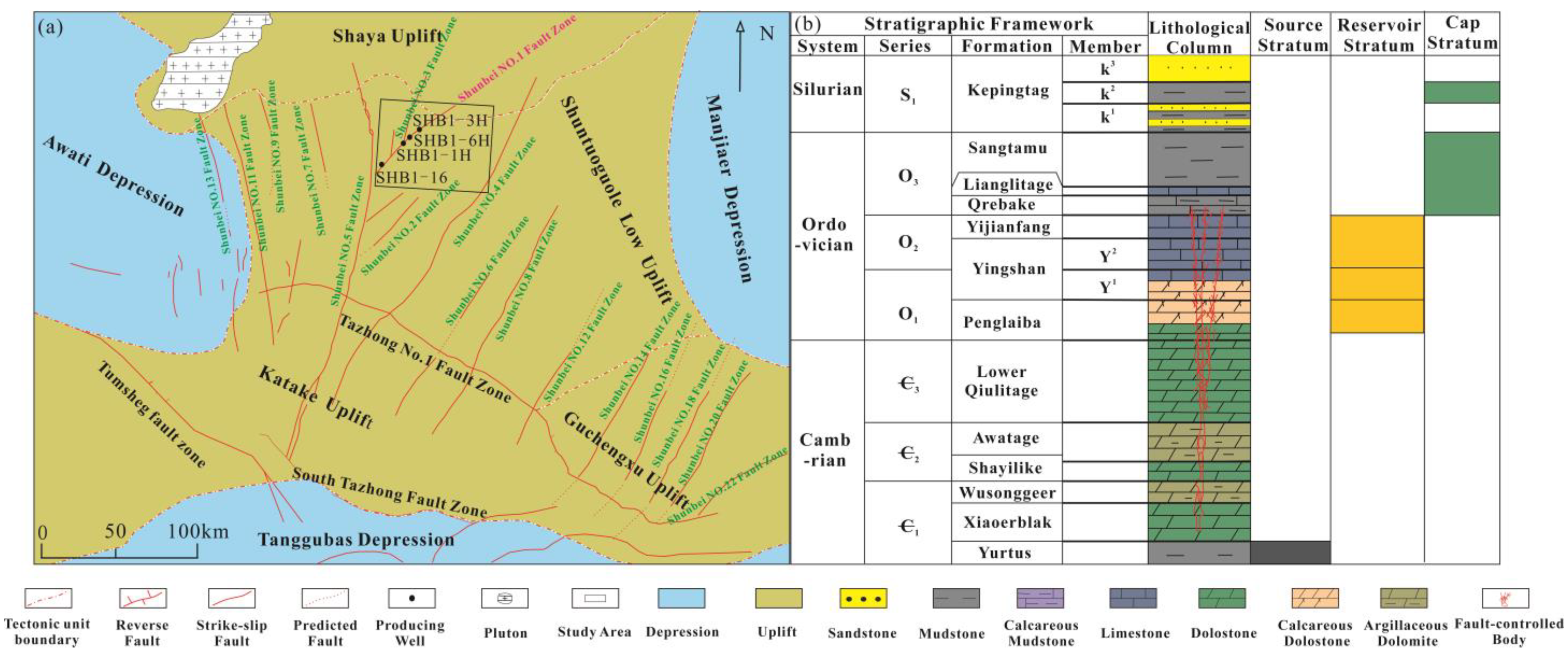
The Shunbei No. 1 Fault Zone is located in the Shunbei 1 block. Drilling results reveal that hydrocarbon reservoirs are distributed along the major intra-block strike–slip fault zones [24,25,26]. The study area is situated in the northern Shuntuoguole Low Uplift, Tarim Basin, at the intersection of the Awati Depression, Shuntuoguole Low Uplift, Manjiaer Depression, and Shaya Uplift, where a series of strike–slip fault zones have developed. The Middle–Lower Ordovician carbonate formations in the area underwent multi-phase tectonic deformation and karstification, resulting in reservoir spaces—including caves, fractured–vuggy, and fractures—and various fault-controlled karst fractured–vuggy reservoir bodies. These were formed through tectonic activity as the precursor with karstification as the subsequent enhancing process [27] (Figure 1). They form an effective reservoir-cap rock assemblage with the overlying thick Upper Ordovician Sangtamu Formation of mudstone and tight limestone [28,29,30,31,32].
Figure 1.
Tectonic setting (a) and stratigraphic column (b) of Shunbei No. 1 Fault Zone, Tarim Basin.
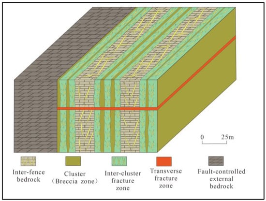
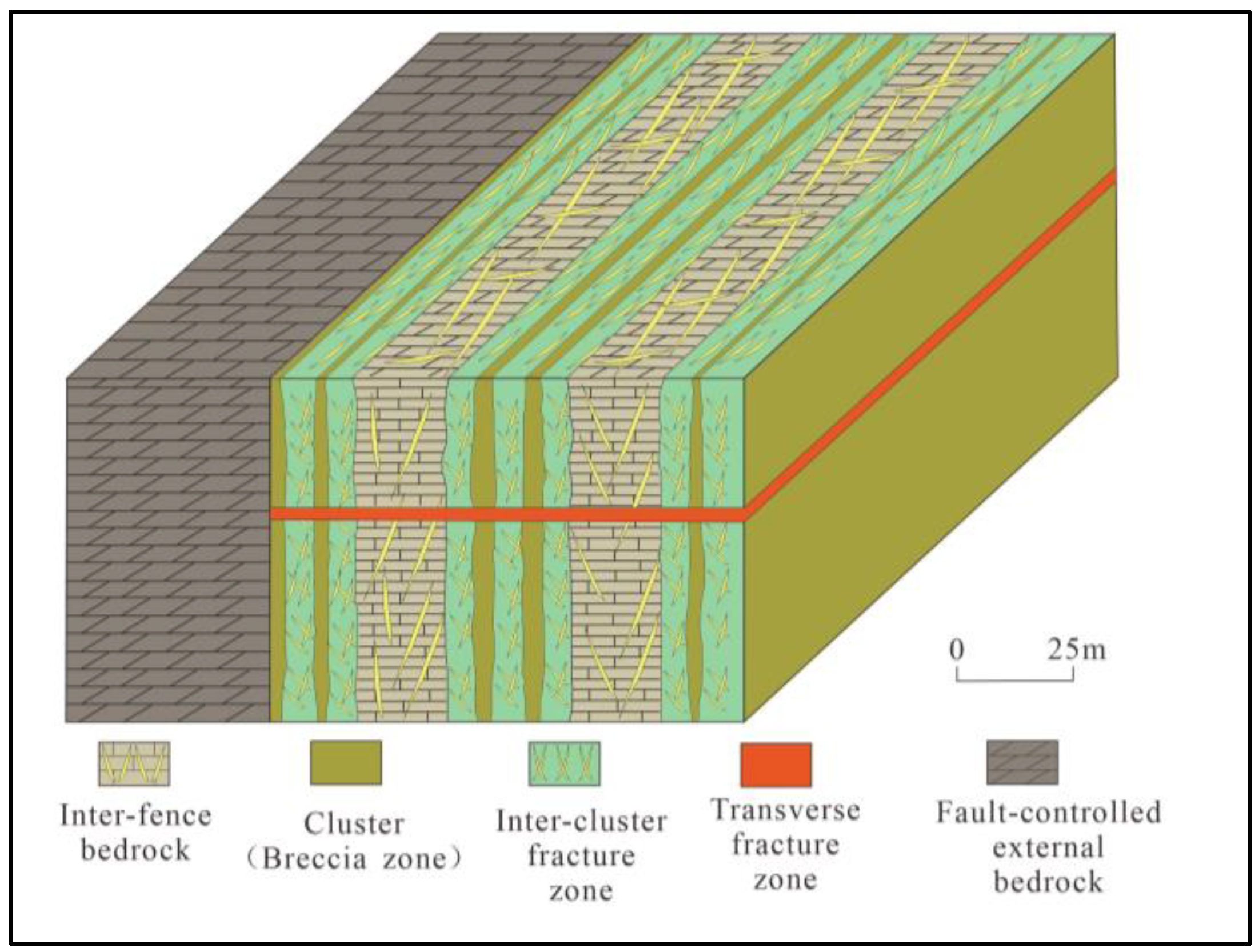
The Shunbei Oil and Gas Field underwent multiple phases of tectonic movements, including the Caledonian, Haixia, Indochina, and Himalayan orogenies [33]. During the early Late Ordovician, sedimentation commenced in the Lianglitage Formation, with the Tarim Basin gradually undergoing “platform-basin differentiation,” with the Katak Uplift region becoming a relatively isolated carbonate plateau. By the Late Ordovician, influenced by the Caledonian Middle Stage III tectonic movement, the Katak Uplift area generally lacks the Silurian Keping Formation strata, whereas the Shuntuo Gole block exhibits relatively complete stratigraphic development [34,35,36,37], this multi-stage sedimentary evolution process made the Shunbei area more conducive to the formation of lithologic trap conditions. Multiple tectonic episodes have endowed the Shunbei No. 1 Fault Zone reservoirs with a distinctive “lattice structure” (Figure 2), This refers to the fault-controlled reservoir bodies distributing in a banded pattern along the strike–slip fault zone. Perpendicular to the fault zone, multiple sets of fracture–vug assemblages are developed, exhibiting an orderly sequence from bedrock to fracture zone, cave zone, fracture zone, and back to bedrock.
Figure 2.
The lattice structure model of cluster filling within vug-like spaces in the Ordovician fault-controlled carbonate reservoirs of the Shunbei No. 1 Fault Zone, Tarim Basin.
3. Models and Methods
3.1. Develop 3D Geological Model
3.1.1. Geostress Interval Analysis
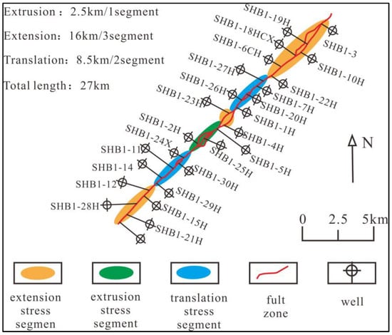
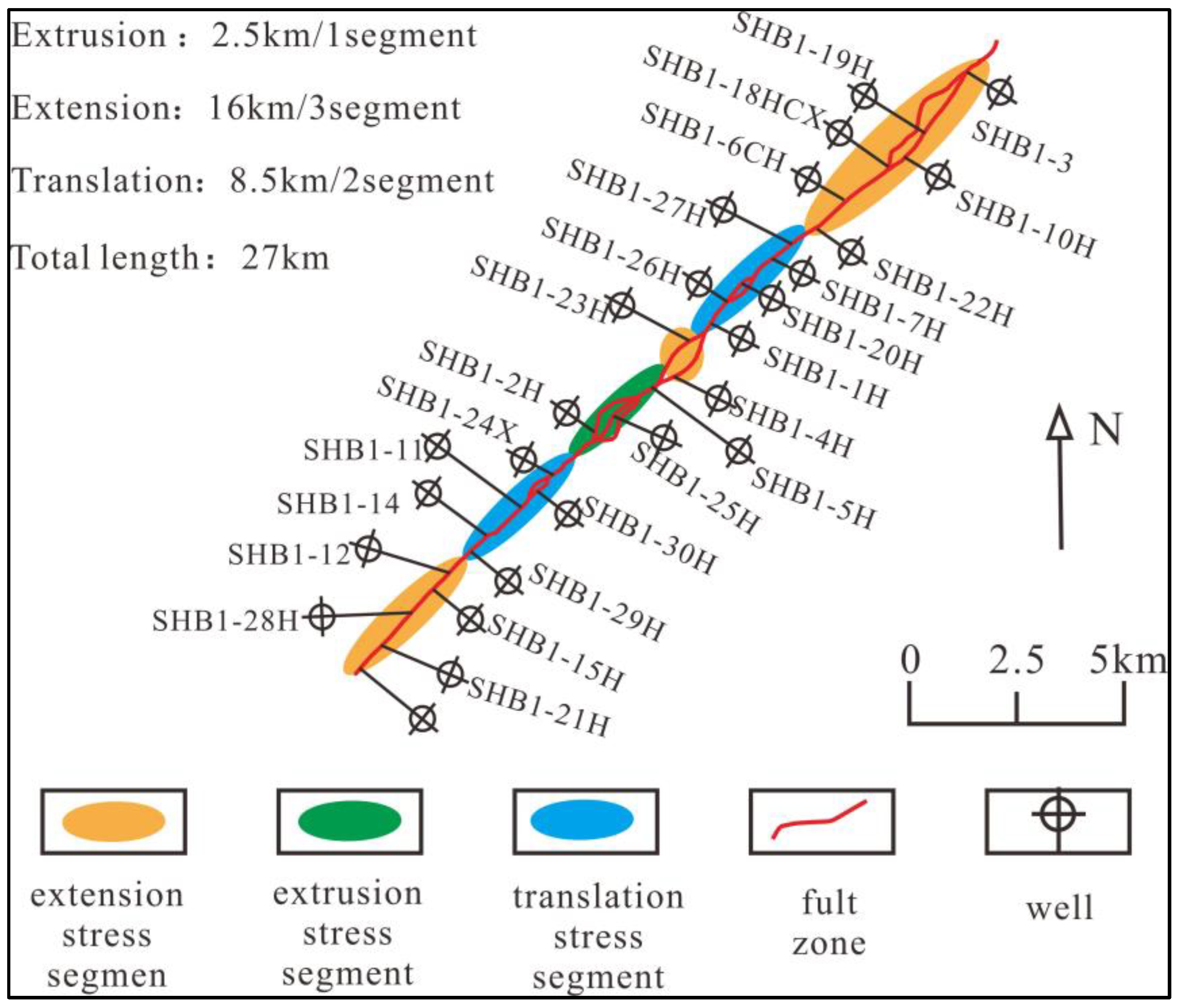
Shang Haojie et al. [37] classified the Ordovician fault-controlled bodies in the Shunbei Oilfield into five hierarchical levels from highest to lowest: strike–slip fault zones, fault-controlled bodies, fracture-cavity-disordered bodies, cavity internal fillings, and microfractures. Higher-level structures exert constraining control over lower-level ones. The Shunbei 1 Fault Zone, controlled by the nearly north–south compressive stress field from the northern Tarim Basin and the oblique compressive and torsional stress field derived from the central Tarim uplift, extends approximately 25 km in a NE40°–45° trend. It converges with the Shunbei 5 Fault Zone and numerous secondary faults trending parallel to the 1 Fault Zone. Based on fundamental principles of geometry and kinematics, Zhang Wenbiao et al. [31] segmented the strike–slip fault zone by analyzing vertical distance variations along the T47 interface (the top surface of the Middle Ordovician Yifang Formation) along the fault zone’s strike. Extensional segment: The profile exhibits an uplifted morphology, primarily characterized by a single developed fault plane, with vug-like spaces “attached” to the fault plane. Extrusion segment: The profile shows a down-warped morphology, featuring multiple fractures with major fault planes on both sides, where vug-like spaces are “hosted between” the fault planes. Translation segment: The profile displays no significant undulation, with relatively gentle structures. They broadly divided the Shunbei No. 1 Fault Zone into six segments along the T47 interface: extension segments, compression segments, and translation segments (Figure 3).
Figure 3.
Three types of stress segment division of the Shunbei No. 1 Fault Zone, Tarim Basin.
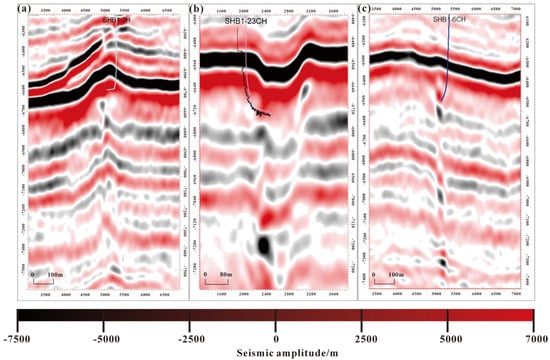
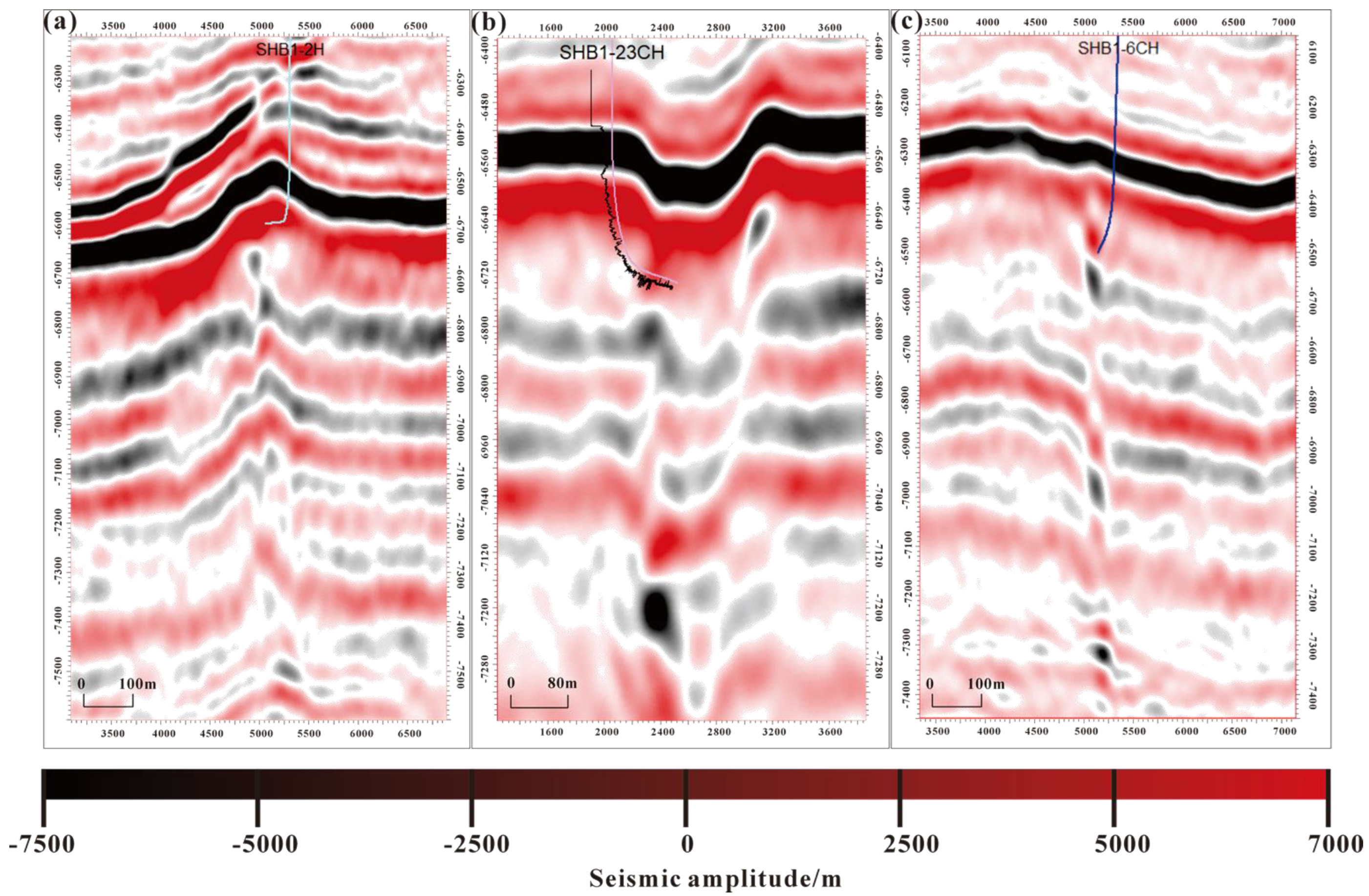
Stress segmentation is primarily determined based on seismic data: Extension segments exhibit concave seismic profiles, often featuring multiple fractures with tensional interactions. Seismic profiles show linear weak reflection characteristics, with large-scale folds appearing on the seismic phase axis and partial faulting occurring. Extrusion segments exhibit uplifted seismic profiles, commonly featuring single or multiple faults exerting compressive forces on each other. Seismic responses show linear weak reflections, with large-scale folding occurring along the seismic phase axis. Translation segments typically display a single fault zone where one side of the strata is uplifted or subsided. Seismic responses exhibit linear weak reflections, accompanied by large-scale folding along the seismic phase axis (Figure 4).
Figure 4.
Three types of stress segment seismic response characteristics of the Shunbei No. 1 Fault Zone, Tarim Basin. (a) Extrusion geostress segment seismic response characteristics; (b) translation geostress segment seismic response characteristics; (c) extension geostress segment seismic response characteristics.
3.1.2. Compartmentalization of Well Groups
The oil and gas reservoirs in the study area are primarily distributed along fault zones [38]. Based on the partitioning characteristics between fault zones and dissolution bodies, Luo Rong [39] and colleagues divided the Shunbei No. 1 Fault Zone and its branches into four static connectivity units. This paper further subdivides them into six dynamically connected units—SHB1-6H, SHB1-1H, SHB1-12H, SHB1-2H, SHB1-11H, and SHB1-24X—by integrating their classification scheme with production dynamics (Table 1).
Table 1.
Division of dynamic connectivity units in the Shunbei No. 1 Fault Zone, Tarim Basin.
3.1.3. Develop a 3D Geological Model
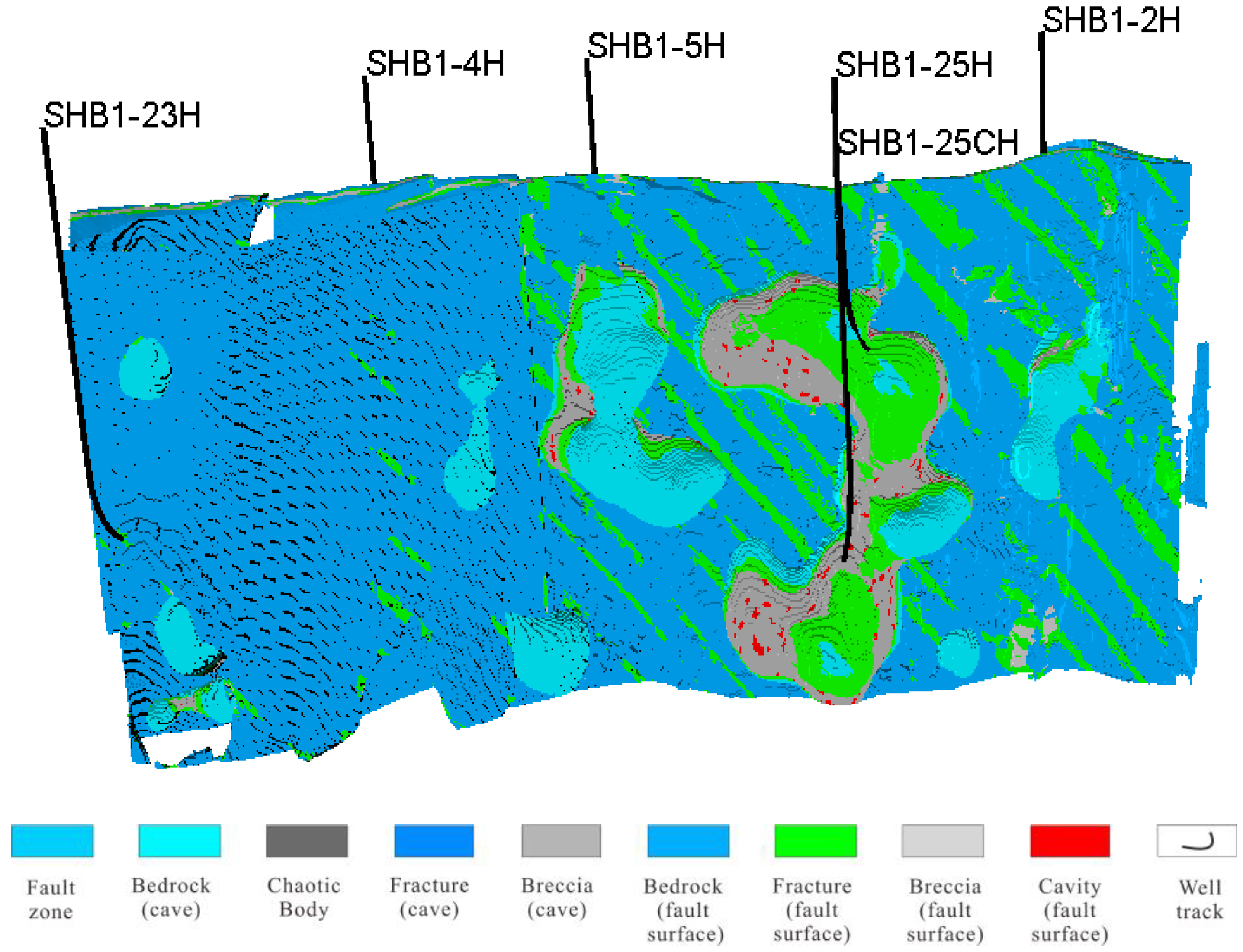
Based on multi-source data including seismic, drilling, core, and logging information, combined with structural locations, reservoir types, and spatial contact relationships, a systematic reservoir development model for the study area was established. Drawing on the “hierarchical constraint and genesis modeling” approach proposed by previous researchers [33], a five-level hierarchical structure was adopted to sequentially construct five geological models: the strike–slip fault influence zone, fault-controlled bodies, vug-like structures, lattice structure zones, and fracture zones. Based on seismic tensor ant tracking and seismic facies analysis, the influenced zones of strike–slip faults were delineated. Deep learning techniques were introduced to predict fault-controlled bodies within weak strike–slip fault segments. By constructing training datasets of typical fault-controlled bodies, a U-net image segmentation deep convolutional neural network was employed for learning and training, followed by the identification and characterization of these bodies. The contours of vug-like structures were extracted from the seismic energy gradient attribute volume. Subsequently, Boolean operations were performed between these contour boundaries and the geological model to ultimately establish a three-dimensional vug-like structure model. Given the relatively simple lattice structure of the clusters inside the vug-like structures and the limited number of intersected wells, object-based indicator point process simulation was adopted for modeling. For the fracture model, the Discrete Fracture Network (DFN) simulation method was primarily utilized.
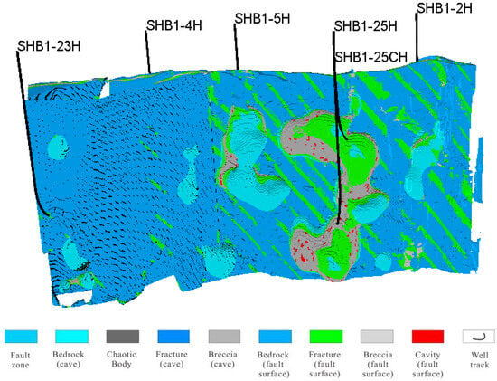
The strike–slip fault influence zone underwent multiple tectonic episodes, forming fault systems of varying scales. Within these systems, rock masses fractured and coalesced into secondary fault-controlled bodies. These reservoirs primarily utilize cross-sectional cavities, breccia pores, and structural fractures as storage spaces, further forming the third-level cave-like units. Drilling revealed that these cave-like units exhibit inter-segment inter-permeability loss characteristics, reflecting the development of grid-like structures internally. Significant property variations exist within the grid-like structures. The fracture-cavern zones primarily feature reservoirs composed of fractures, breccia zones, and cavities, exhibiting a clustered filling pattern. If the inter-cluster zones are bedrock-fracture zones, lateral connectivity is favorable; otherwise, fluid exchange is restricted. Cluster filling prediction and fracture characterization constitute the fourth and fifth modeling levels, respectively. Deterministic modeling methods are employed for seismic attribute extraction, while cavern-like internal cluster structures and fracture systems are characterized using stochastic modeling. Ultimately, integrating models from all levels constructs a comprehensive three-dimensional geological model (Figure 5).
Figure 5.
Three-dimensional model of well group SHB1-2H in the Shunbei No. 1 Fault Zone, Tarim Basin.
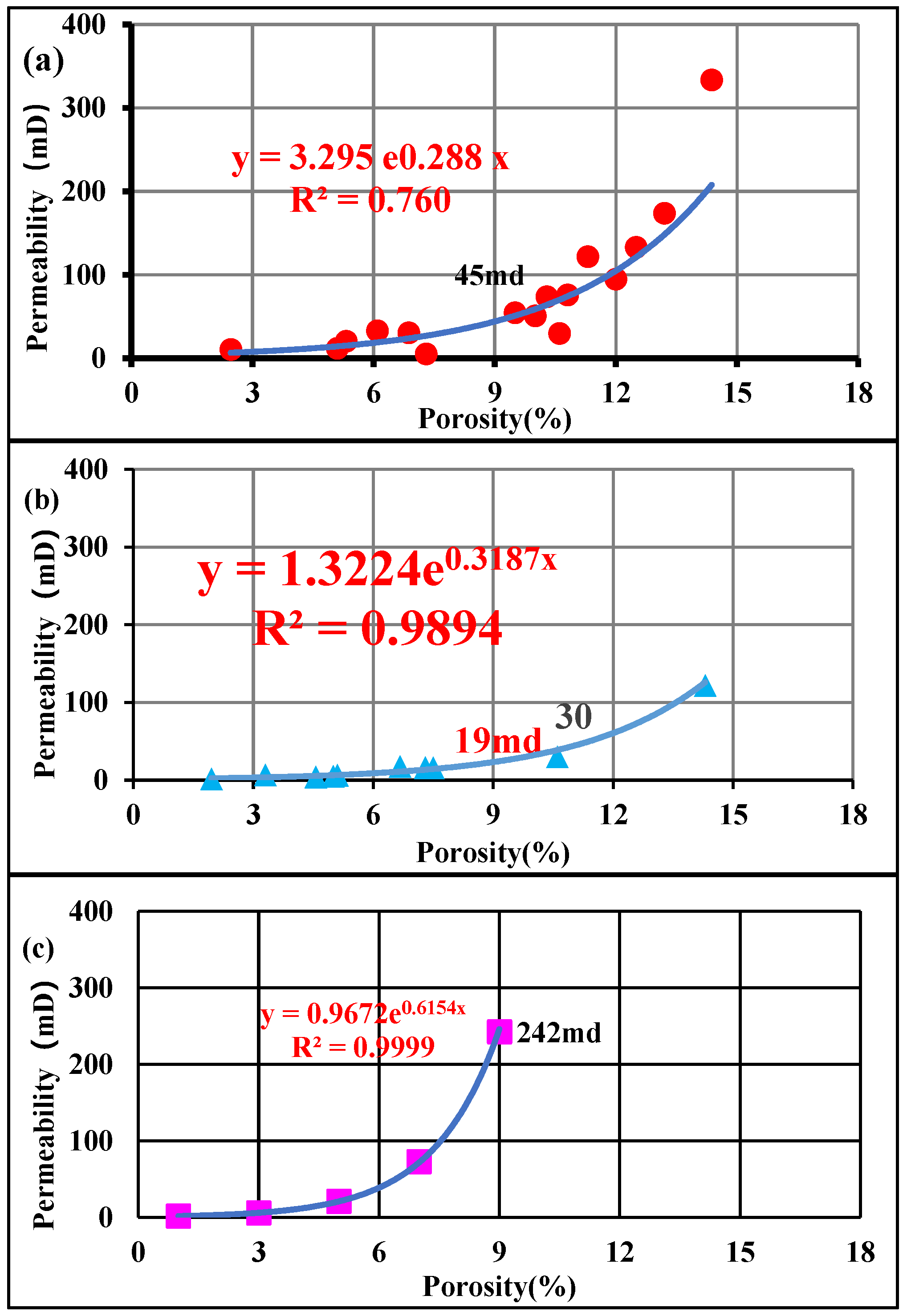
The study area has limited well data, making it difficult to directly use well data as conditional constraints for property modeling. However, with full seismic coverage, a porosity volume derived from acoustic impedance inversion was used to constrain the porosity distribution ranges for different reservoir bodies. The geological facies model was converted into a trend volume and, combined with variogram constraints on porosity distribution, a porosity property curve was established. Based on the relationship between water absorption index and permeability, and the relationship between loss rate and porosity, porosity–permeability correlation curves for different reservoir bodies were developed (Chart 1), thereby constructing the attribute model.
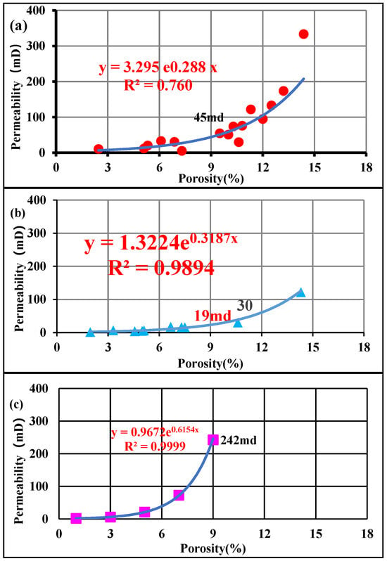
Chart 1.
Porosity–permeability relationship curves for different reservoir properties in the Shunbei No. 1 Fault Zone (modeled by type); (a) porosity–permeability relationship curves for vuggy reservoir properties; (b) porosity–permeability relationship curves for fracture-vuggy reservoir properties; (c) porosity–permeability relationship curves for fractured reservoirs.
3.2. Reservoir Simulation
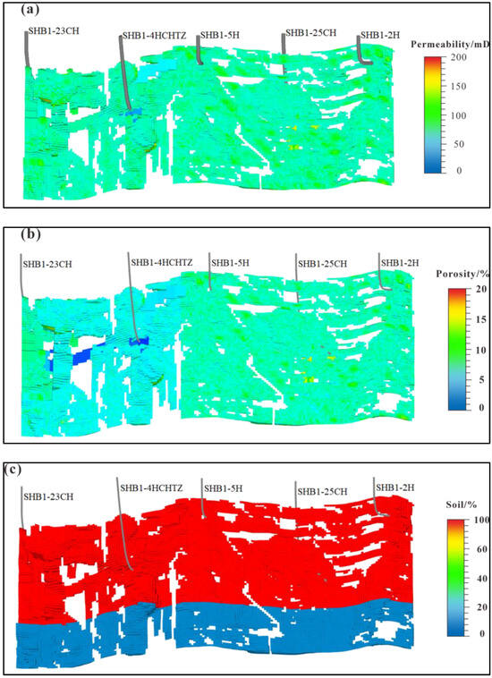
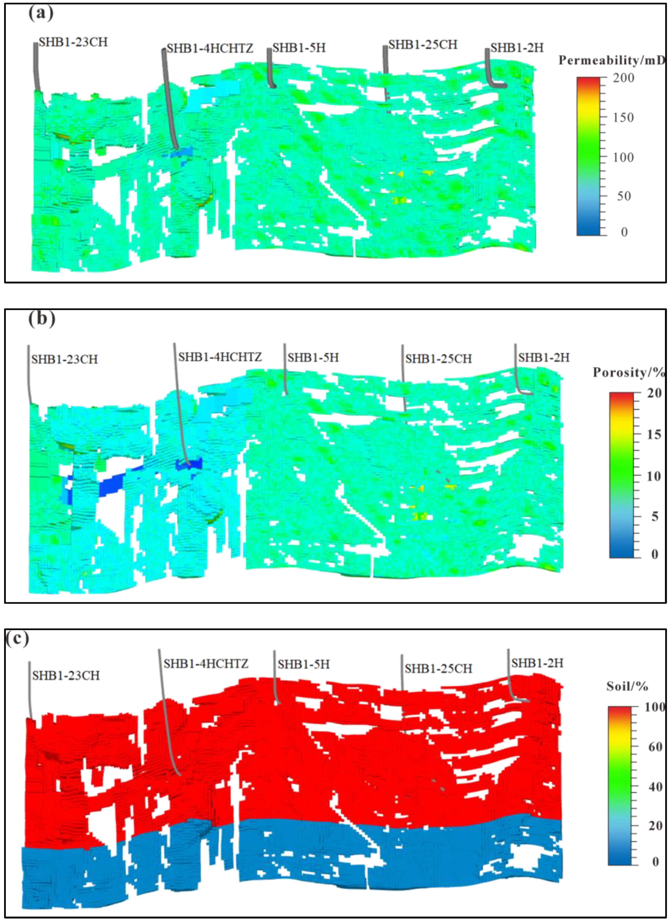
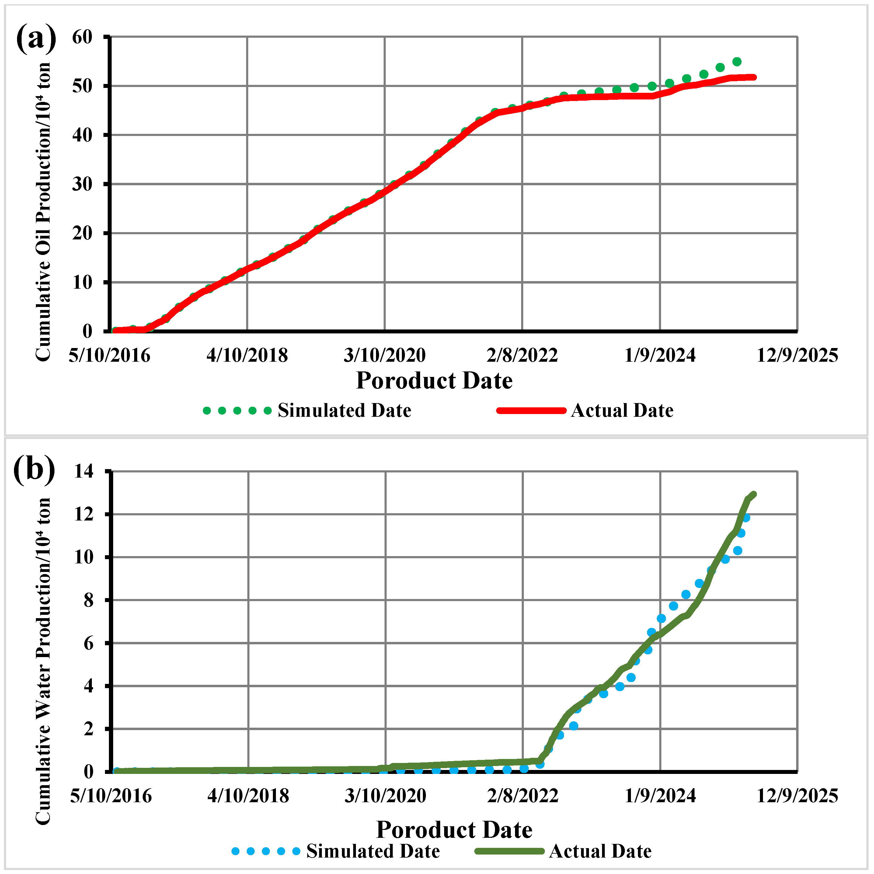
In the tNavigator 22.1 numerical simulation software, based on the three-dimensional geological model, the grid was coarsened to 20 × 6 × 9 m (during property upscaling, the property value occupying the largest proportion within the current grid was assigned to the upscaled grid). Static parameter fields, including permeability (Figure 6a), porosity (Figure 6b), and saturation (Figure 6c), were sequentially defined as initial conditions. Dynamic parameters were further defined, encompassing the production time series, model type (This study employs a compositional model), grid structure, fluid properties (density, viscosity, formation volume factor, and compressibility), rock properties (compressibility), relative permeability curves, and the temperature–pressure field. Finally, historical production data from well groups and individual wells (such as fluid production rates and pressure) were incorporated. The model was calibrated through data matching to verify its reliability and prediction accuracy (Chart 2). And then, following the completion of numerical simulation work on liquid production rate and other parameters, statistics on the remaining reserves were compiled (Table 2).
Figure 6.
Numerical simulation model of well group SHB1-2H in the Shunbei No. 1 Fault Zone, Tarim Basin. (a) Numerical permeability model; (b) numerical porosity model; (c) numerical oil saturation model.
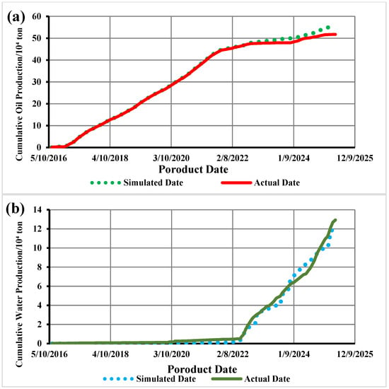
Chart 2.
Numerical simulation matching curve for liquid production rate of the SHB1-2H well group in the Shunbei No. 1 Fault Zone. (a) Cumulative oil production history match; (b) cumulative water production history match.
Table 2.
Remaining reserves in the Shunbei No. 1 area, Tarim Basin, post numerical simulation.
4. Results and Discussion
The Shunbei No. 1 Fault Zone is a deep-marine carbonate hydrocarbon reservoir characterized by polyphase tectonic evolution and the development of multi-stage fault systems [40]. The reservoir primarily consists of fault-dissolution bodies, with storage spaces encompassing various types such as fracture-type, cave-type, and fracture-cavity-type. The formation is fractured with strong heterogeneity, where fractures serve dual functions as flow pathways and storage spaces, exhibiting distinct vertical stratification. Following prior depletion-induced natural flow, water injection, and gas injection development, reservoir dynamics have become complex, with unclear residual oil distribution patterns hindering further exploitation. This study employs three-dimensional detailed geological modeling and numerical simulation to systematically reveal residual oil distribution patterns, providing a basis for development adjustment strategies.
4.1. Distribution Characteristics of Remaining Oil
Based on the completion of production history matching, numerical simulation results for the study area indicate that the distribution of residual oil in the target well group is primarily governed by two major factors: first, the unique stratigraphic conditions of the study area—fault-related dissolution reservoirs coupled with fracture–vug storage spaces; second, the injection–production relationship within the well group. Accordingly, residual oil can be classified into the following six typical types:
4.1.1. Unswept Remaining Oil
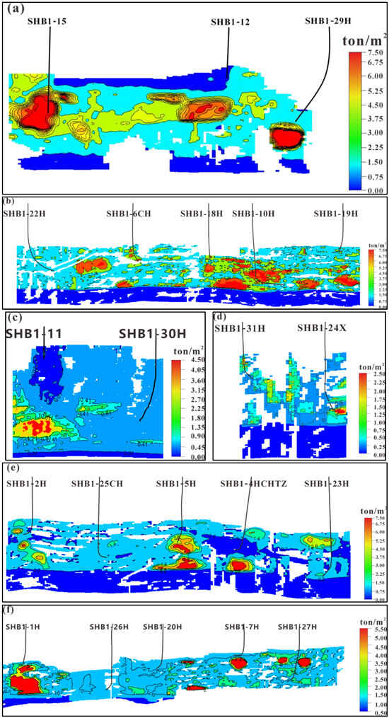
Taking the SHB1-12 well group as an example, it is located within a extension to weakly extrusion transition segment. The storage spaces consist of interconnected fracture–vug units. However, due to the pull-apart effects, multiple preferential pathways have formed. The main injection well, SHB1-12, did not penetrate the fracture conduits of the underlying main fracture–vug system. This resulted in the injected media being largely retained within the upper pathways, making it difficult to effectively displace and replace the crude oil in the principal fracture–vug units (Figure 7a).
Figure 7.
Distribution characteristics of remaining oil in well groups of the Shunbei No. 1 Fault Zone, Tarim Basin. (a) Remaining oil saturation map of well group SHB1-12; (b) remaining oil saturation map of well group SHB1-6H; (c) remaining oil saturation map of well group SHB1-11; (d) remaining oil saturation map of well group SHB1-24X; (e) remaining oil saturation map of well group SHB1-2H; (f) remaining oil saturation map of well group SHB1-1H.
4.1.2. Insufficient Well Control Remaining Oil
The SHB1-6CH well group is situated in a strongly extensional segment. Due to the intense pull-apart effect, the reservoir bodies exhibit a high degree of dissolution/vug development, resulting in poor lateral connectivity and strong vertical heterogeneity. Consequently, the current injection–production well pattern has limited control over the reserves. Coupled with the low displacement efficiency of water/gas injection, a significant volume of remaining oil is not effectively mobilized and remains trapped within the reservoir (Figure 7b).
4.1.3. Well Pattern-Dependent Remaining Oil
The SHB1-11 well group consists of only two wells: SHB1-11 and SHB1-30H. Initially, the development pattern was with SHB1-11 as the producer and SHB1-30H as the injector. Following a sharp decline in the recovery performance of SHB1-11, the pattern was converted, with SHB1-11 becoming the injector and SHB1-30H the producer. Furthermore, the well group is located in a strike–slip to weakly extensional segment, where fractures are well-developed along the strike direction. This resulted in effective water/gas displacement efficiency, which conversely led to a significant volume of remaining oil being trapped in the lower fracture–vug body of the SHB1-11 well (Figure 7c).
4.1.4. Channeling-Dominated Remaining Oil
The SHB1-24X well group consists of only two wells: SHB1-24X and SHB1-30H. Located in a strike–slip to weakly extensional stress segment, the reservoir exhibits relatively well-developed fractures along the strike direction, and a preferential pathway exists between the two wells. Furthermore, after gas injection in the SHB1-24X well ceased and water injection commenced, a casing breach/leakage occurred. This incident led to the SHB1-30H well experiencing rapid water breakthrough shortly after being put into production, resulting in a significant volume of remaining oil being left along both sides of the waterflooding path (Figure 7d).
4.1.5. Attic Remaining Oil
Due to its location within a “Extension + Extrusion” composite stress segment, the SHB1-2H well group features a high-angle fracture network. While this network offers good lateral connectivity, it lacks effective downward conduits. Concurrently, the pull-apart segment tends to form “inverted-bottle” shaped solution cavities, characterized by a broad top and a narrow base, often underlain by low-permeability fillings. These cavities collectively create fluid stagnation zones and physical barriers. The combination of these factors leads to a “preferential pathway shielding” effect. Injected fluids preferentially migrate rapidly along dominant fracture channels laterally or upward, bypassing the lower oil zones. Consequently, the crude oil at the bottom becomes trapped at the base of the fracture–vug body due to the combined effects of gravity segregation, high capillary force adsorption, and insufficient driving pressure, forming remaining oil that is difficult to mobilize.
4.1.6. Isolated Remaining Oil
The SHB1-1H well group is located within a fractured zone formed by the intersection of two fault zones, belonging to a translational stress segment. Although the reservoir is relatively well-developed, the fractures and cavities are divided by multiple filled or unopened fractures, resulting in extremely poor connectivity. This causes the reservoir to be fragmented, with residual oil distributed in isolated, star-like patterns (Figure 7f).
4.2. Patterns of Remaining Oil Distribution
Following the stages of natural flow, water flooding, and gas injection development in the Shunbei No. 1 Fault Zone, the distribution of remaining oil is fundamentally governed by a three-level coupling of “structure-reservoir-well pattern”. The primary factor is the segmentation of the strike–slip faults (extensional, compressional, and strike–slip segments), which determines the macro-morphology of reservoir bodies (e.g., large-scale caverns or fracture zones) and the preferential flow network. The secondary factor is the internal reservoir architecture controlled by tectonics, such as the “inverted-bottle” shape of caverns, low-permeability fillings at their bases, and the vertical connectivity of fractures, which directly create fluid stagnation zones and flow barriers. Finally, the configuration relationship between the injection–production well pattern and this geological architecture is critical. If the well pattern fails to effectively drive the preferential pathways or contact the stagnation zones, it solidifies specific remaining oil patterns (e.g., bottom-trapped or preferential-pathway-shielded types). Consequently, the variation in patterns results from the combined effect of reservoir heterogeneity under specific tectonic backgrounds and the development well pattern. Therefore, based on the characteristics of remaining oil distribution from the numerical simulation and integrated with reservoir geological features, three major categories with five sub-types of remaining oil distribution patterns are summarized (Table 3).
Table 3.
Distribution characteristics of three types of remaining oil in the Shunbei No. 1 Fault Zone, Tarim Basin.
4.2.1. Local Low Permeability, Weak Hydrodynamics
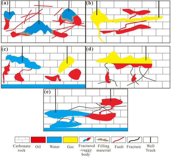
Due to differences in tectonic stress, dissolution, and filling processes, the reservoir bodies exhibit strong compartmentalization. Areas with intense filling or weak dissolution are prone to forming low-permeability zones, resulting in limited sweep efficiency during development and displacement (Figure 8a). Remaining oil tends to be enriched in a star-shaped distribution within filled portions of fracture–vug systems or in poorly connected dissolved pore spaces. (Figure 8b). Residual oil accumulates in a star-like pattern within the filled zones or weakly eroded areas. Research indicates that 70–80% of the storage bodies within karstic reservoirs are filled [41]. Effectively mobilizing this residual oil holds significant importance for development outcomes.
Figure 8.
Distribution patterns of remaining oil in Shunbei No. 1 Fault Zone, Tarim Basin. (a) Isolated distribution patterns of remaining oil; (b) channeling-dominated distribution patterns of remaining oil; (c) insufficient well control distribution patterns of remaining oil; (d) attic distribution patterns of remaining oil; (e) well pattern-dependent distribution patterns of remaining oil.
4.2.2. Shielded Connectivity Pathways
(1) Type II channeling-dominated oil: Within the well group, multiple parallel-connected pathways exist between wells or between the aquifer and production wells. Injected water/gas or aquifer influx rapidly advances along certain high-permeability channels, such as large fractures, toward the production well. While this provides effective displacement of oil and gas along the dominant path, it shields other channels from effective sweep. Consequently, displacement efficiency in these other pathways is poor, and the overall oil–gas replacement within the fracture–vug body of the production well remains insufficient, thereby leading to the formation of remaining oil. (Figure 8b).
(2) Type II-b insufficient well control oil: Reservoir bodies subjected to pull-apart stress exhibit severe vug development and strong spatial heterogeneity in fracture–vug distribution. This is particularly challenging when the fracture–vug bodies are small in scale, internally sealed, and disconnected from the aquifer. Furthermore, due to reserve limitations, it is not feasible to establish dedicated injection–production patterns for them individually. Development efforts are thus limited to attempting water or gas injection through producers in the primary fracture–vug bodies to displace hydrocarbons. This approach results in weak control over the secondary fracture–vug bodies, leading to the entrapment of remaining oil. (Figure 8c).
4.2.3. Well Pattern-Dependent
(1) Type III-a attic oil: The hydrocarbon storage spaces in the No. 1 belt are predominantly fracture–vug bodies combined with fault-plane fractures. Production wells are mostly placed at the tops or high points of these fracture–vug bodies. During the depletion development stage, the displacement and replacement of hydrocarbons are relatively effective in the higher sections of primary, isolated, or aquifer-connected fracture–vug bodies. Subsequently, in the water or gas flooding stages, injected water or gas tends to migrate laterally. Particularly after gas flooding, due to the density difference between gas and oil, the remaining oil becomes confined to the lower sections (Figure 8d).
(2) Type III-b well pattern-dependent oil: Excellent inter well connectivity exists, with fracture-cavity bodies connected by cross-sections or multiple fractures. No prominent displacement pathways are present, allowing injected fluids to migrate along multiple paths. Residual oil accumulates around production wells (Figure 8e).
4.3. Recommendations for Remaining Oil Potential Development
Fracture-cavity-type carbonate reservoirs exhibit spatially discrete distributions of fracture-cavity structures, resulting in significant differences in enhanced recovery approaches compared to layered continuous-medium reservoirs. In layered continuous-medium reservoirs, injection sweep efficiency and oil displacement efficiency directly impact recovery rates. Enhanced recovery is achieved by improving sweep efficiency (e.g., through polymer injection) and displacement efficiency (e.g., via surfactant injection). Previous studies indicate that recovery in fractured–karstic carbonate reservoirs also depends on the well network’s control over reserves, as expressed by the following equation [41]:
In the formula: ED—oil recovery efficiency, %; ES—reserve control level, %; EV—spillover coefficient, %; and η—recovery rate, %.
4.3.1. Improve Well Control
Remaining oil in Category I, II-b, and III-a reservoirs stems from poor connectivity between fractures and cavities, coupled with inadequate well control. The key to enhancing recovery rates lies in optimizing well placement, increasing sidetrack drilling, and expanding the reservoir coverage of the well network. For Category I and III-a remaining oil, supplementary “secondary development” measures such as surfactant injection, gas injection-thrusting, or gas-driven gravity separation can be employed. Gas injection (particularly nitrogen) has become an effective energy supplementation method in the Shunbei Oilfield, as gravity separation forms a secondary gas cap in the upper part of fractures and cavities, enabling non-miscible flooding.
4.3.2. Reservoir Flow Field Modification
Remaining oil of Type II-a primarily forms when injected fluids advance through high-permeability channels, blocking hydrocarbon flow in low-permeability zones. Reservoir flow patterns can be modified by adjusting injection–production parameters or sealing high-permeability channels, thereby enhancing gravity-driven segregation and capillary effects to improve sweep efficiency. For remaining oil of Type III-b, potential extraction requires optimizing injection–production well network structures and parameters.
It should be noted that multiple remaining oil types may coexist within the same reservoir space or even the same fracture-cavity system. Due to variations in development conditions such as well locations and reserves, recovery strategies must be flexibly customized and comprehensively applied.
5. Conclusions
(1) The reservoir in the fault-controlled body of the Shunbei 1 Fault Zone has undergone multiple phases of tectonic evolution, forming a unique reservoir architecture characterized by a “lattice-like structure.” It exhibits highly developed fractures, with breccia zones, and bedrock areas coexisting in an interwoven pattern.
(2) Reservoir spaces in the study area are primarily characterized by “string-of-pearls fissure-cavity bodies + cross-sectional fractures.” Remaining oil distribution during development is jointly controlled by reservoir body characteristics and development methods, categorizable into three major types: locally low-permeability weak-hydrodynamic, interconnected-channel shielded, and injection–production well network-controlled, which are further subdivided into five sub-types.
(3) Remaining oil recovery should focus on enhancing well control and flow field modification. Comprehensive measures including well network optimization, gas injection and withdrawal, parameter adjustment, and channel sealing should be implemented to improve reservoir control and sweep efficiency, achieving high-efficiency development.
Author Contributions
Conceptualization, J.S. and S.J.; Methodology, J.S. and W.C.; Software, S.J.; Validation, P.C.; Formal analysis, J.S., L.L. and Z.C.; Investigation, W.C.; Resources, J.S.; Data curation, J.S., W.C. and P.C.; Writing—original draft, J.S. and Z.C.; Writing—review and editing, J.S., S.J., L.L. and P.C.; Visualization, J.S. and S.J.; Supervision, L.L.; Funding acquisition, Z.C. All authors have read and agreed to the published version of the manuscript.
Funding
This research received no external funding.
Data Availability Statement
The original contributions presented in this study are included in the article. Further inquiries can be directed to the corresponding author.
Conflicts of Interest
Author Wanjie Cai was employed by the Sinopec Northwest Oilfield No. 2 Oil Production Plant. Author Lingyan Luo was employed by Changqing Oilfield Branch, PetroChina Company Limited. The remaining authors declare that the research was conducted in the absence of any commercial or financial relationships that could be construed as a potential conflict of interest.
References
- Hu, A.; She, M.; Shen, A.; Qiao, Z.; Li, W.; Du, Q.; Yuan, C. Visualization Simulation Experiments and Porosity Evolution Mechanisms of Deep to Ultra-Deep Carbonate Reservoirs. Pet. Explor. Dev. 2025, 52, 377–390. [Google Scholar] [CrossRef] [Scilit]
- Ma, Y.; Guo, X.; Guo, T.; Huang, R.; Cai, X.; Li, G. The Puguang Gas Field: New Giant Discovery in the Mature Sichuan Basin, Southwest China. AAPG Bull. 2007, 91, 627–643. [Google Scholar] [CrossRef] [Scilit]
- Cheng, Y.; Luo, X.; Zhuo, Q.; Gong, Y.; Liang, L. Description of Pore Structure of Carbonate Reservoirs Based on Fractal Dimension. Processes 2024, 12, 825. [Google Scholar] [CrossRef] [Scilit]
- MA, Y.; CAI, X.; YUN, L.; LI, Z.; LI, H.; DENG, S.; ZHAO, P. Practice and Theoretical and Technical Progress in Exploration and Development of Shunbei Ultra-Deep Carbonate Oil and Gas Field, Tarim Basin, NW China. Pet. Explor. Dev. 2022, 49, 1–20. [Google Scholar] [CrossRef] [Scilit]
- Wei, L.; Di, B.; Wei, J. Analysis of Seismic Response Characteristics of Fractured Carbonate Reservoirs Based on Physical Model (Tarim Basin). Appl. Sci. 2024, 14, 3775. [Google Scholar] [CrossRef] [Scilit]
- Dyman, T.S.; Crovelli, R.A.; Bartberger, C.E.; Takahashi, K.I. Worldwide Estimates of Deep Natural Gas Resources Based on the U.S. Geological Survey World Petroleum Assessment 2000. Nat. Resour. Res. 2002, 11, 207–218. [Google Scholar] [CrossRef] [Scilit]
- Perry, W.J.J. Structural Settings of Deep Natural Gas Accumulations in the Conterminous United States. U.S. Geol. Surv. Bull. 1997, 2146, 41–46. [Google Scholar]
- Erskine, R.D. String of Drilling Successes Puts El Paso Out Front in Deep Gas. Am. Oil Gas Report. 2001, 44, 44–54. [Google Scholar]
- Wyman, R.E. Challenges of Ultradeep Drilling. In The Future of Energy Gases; Howell, D.G., Ed.; U.S. Geological Survey Professional Paper 1570; U.S. Geological Survey: Reston, VA, USA, 1993; pp. 205–216. [Google Scholar]
- Li, Y. Development Theories and Methods of Fracture-Vuggy Carbonate Reservoirs; Academic Press: London, UK, 2017. [Google Scholar]
- Tian, F.; Jin, Q.; Lu, X.; Lei, Y.; Zhang, L.; Zheng, S.; Zhang, H.; Rong, Y.; Liu, N. Multi-Layered Ordovician Paleokarst Reservoir Detection and Spatial Delineation: A Case Study in the Tahe Oilfield, Tarim Basin, Western China. Mar. Pet. Geol. 2016, 69, 53–73. [Google Scholar] [CrossRef] [Scilit]
- Tang, B.; Ren, K.; Lu, H.; Li, C.; Geng, C.; Wei, L.; Chai, Z.; Wu, S. Study on Residual Oil Distribution Law during the Depletion Production and Water Flooding Stages in the Fault-Karst Carbonate Reservoirs. Processes 2023, 11, 2147. [Google Scholar] [CrossRef] [Scilit]
- Yao, J.; Chen, Z.; Jiang, C.; Peng, X. An Integrated Numerical Study of CO2 Storage in Carbonate Gas Reservoirs with Chemical Interaction between CO2, Brine, and Carbonate Rock Matrix. Appl. Sci. 2024, 14, 6002. [Google Scholar] [CrossRef] [Scilit]
- Yan, H.; Pan, Z.; Zhang, B.; Meng, X.; He, J.; Liu, Y.; Si, L. Visualization Experimental Study on Gas Injection for Enhanced Oil Recovery in Fractured-Vuggy Carbonate Reservoirs after Water Flooding. Pet. Sci. Bull. 2025, 10, 565–574. [Google Scholar]
- Radwan, M.S.; Gobashy, M.; Dahroug, S.; Raslan, S. Exploring Carbonate Reservoirs Potential, North Egypt. Contrib. Geophys. Geod. 2024, 54, 49–66. [Google Scholar] [CrossRef] [Scilit]
- Wang, J.; Xu, Z.; Liu, J.; Feng, J.; Wang, Q.; Jiao, Y.; Zhang, Q.; Liu, H. Distribution Rules of Remaining Oil by Bottom Water Flooding and Potential Exploitation Strategy in Fault- Controlled Fractured-Vuggy Reservoirs. Pet. Explor. Dev. 2024, 51, 1271–1286. [Google Scholar] [CrossRef] [Scilit]
- Chen, F.; Peng, D.; Wang, N.; Wang, Z.; Zeng, Q. Water Injection and Gas Injection to Enhance Oil Recovery in Yingmai 2 Fracture-vuggy Reservoir. J. Southwest Pet. Univ. 2024, 46, 149–158. [Google Scholar] [CrossRef]
- Rong, Y.; Zhao, J.; Lu, X.; Li, X.; Li, X. Remaining Oil Distribution Patterns and Potential-Tapping Countermeasures in Carbonate Fracture-Cavity Reservoir. Acta Pet. Sin. 2014, 35, 1138–1146. [Google Scholar]
- Zheng, S.; Yang, M.; Kang, Z.; Liu, Z.; Long, X.; Liu, K.; Li, X.; Zhang, S. Controlling Factors of Remaining Oil Distribution after Water Flooding and Enhanced Oil Recovery Methods for Fracture-Cavity Carbonate Reservoirs in Tahe Oilfield. Pet. Explor. Dev. 2019, 46, 786–795. [Google Scholar] [CrossRef] [Scilit]
- Tang, Y.; Wu, B.; Zhou, H. Distribution and Development Strategies of Remaining Oil Controlled by Different Factors in Fractured-Vuggy Oil Reservoirs. Oil Drill. Prod. Technol. 2018, 40, 483–488. [Google Scholar] [CrossRef]
- Goudarzi, A.; Delshad, M.; Mohanty, K.K.; Sepehrnoori, K. Surfactant Oil Recovery in Fractured Carbonates: Experiments and Modeling of Different Matrix Dimensions. J. Pet. Sci. Eng. 2015, 125, 136–145. [Google Scholar] [CrossRef] [Scilit]
- Gazizyanov, A.R.; Chvertkov, A.G.; Gubaev, A.V. Identification of Remaining Oil in Place on Local Uplifts of the White Tiger Basement (Russian). Neft. Khozyaystvo—Oil Ind. 2023, 2023, 17–19. [Google Scholar] [CrossRef] [Scilit]
- Alimohammadi, N.; Pooladi-Darvish, M.; Rostami, B.; Khosravi, M. Improvement to Gravity Drainage Recovery by Repressurization as a Criterion to Screen and Rank Naturally Fractured Reservoirs for Gas Injection. SPE Reserv. Eval. Eng. 2022, 26, 1073–1090. [Google Scholar] [CrossRef] [Scilit]
- Yun, L.; Deng, S. Structural Styles of Deep Strike-Slip Faults in Tarim Basin and the Characteristics of Their Control on Reservoir Formation and Hydrocarbon Accumulation: A Case Study of Shunbei Oil and Gas Field. Acta Pet. Sin. 2022, 43, 770–787. [Google Scholar]
- Deng, S.; Li, H.; Zhang, Z.; Zhang, J.; Yang, X. Structural Characterization of Intracratonic Strike-Slip Faults in the Central Tarim Basin. AAPG Bull. 2019, 103, 109–137. [Google Scholar] [CrossRef] [Scilit]
- Ban, G. Key Drilling Techniques in No.1 and No.5 Fault Zones of Shunbei Oilfield. J. Pet. Univ. Staff Work. 2023, 36, 21–23. [Google Scholar]
- Kang, Y.Z. Reservoir Rock Characteristics of Paleozoic Marine Facies Carbonate Rock in the Tarim Basin. Pet. Geol. Exp. 2007, 3, 217–223. [Google Scholar]
- Jiao, F. Significance and Prospect of Ultra-Deep Carbonate Fault-Karst Reservoirs in Shunbei Area, Tarim Basin. Oil Gas Geol. 2018, 39, 207–216. [Google Scholar] [CrossRef]
- Lu, X.; Hu, W.; Wang, Y.; Li, X. Characteristics and Development Practice of Fault-Karst Carbonate Reservoirs in Tahe Area, Tarim Basin. Oil Gas Geol. 2015, 36, 347–355. [Google Scholar] [CrossRef]
- Yang, D.; Lu, X.; Bao, D.; Cao, F.; Wang, Y.; Wang, M.; Xie, R. New Insights into the Genetic Types and Characteristics of the Ordovician Marine Fault-Karst Carbonate Reservoirs in the Northern Tarim Basin. Oil Gas Geol. 2024, 45, 357–366. [Google Scholar]
- Zhang, W.; Duan, T.; Zhao, H.; Ma, Q.; Bao, D. Hierarchical Characteristics and 3D Modeling of Fault-Controlled Paleokarst Systems: A Case Study of Shunbei1 Strike-Slip Fault Zone. Sci. Technol. Eng. 2021, 21, 12094–12108. [Google Scholar] [CrossRef]
- Chen, S.; He, Y.; Wang, L.; Niu, Y.; Lu, Z. Architecture Characterization and 3D Geological Modeling of Ordovician Carbonate Reservoirs in Shunbei No. 1 Fault Zone, Tarim Basin. Lithol. Reserv. 2024, 36, 124–135. [Google Scholar]
- Deng, S.; Liu, Y.; Liu, J.; Han, J.; Wang, B.; Zhang, R. Structural Styles and Evolution Models of Intracratonic Strike-slip Faults and the Implications for Reservoir Exploration and Appraisal: A Case Study of the Shunbei Area, Tarim Basin. Geotecton. Metallog. 2021, 45, 1111–1126. [Google Scholar] [CrossRef]
- Jia, C.; Ma, D.; Yuan, J.; Wei, G.; Yang, M.; Yan, L.; Tian, F.; Jiang, L. Structural Characteristics, Formation & Evolution and Genetic Mechanisms of Strike–Slip Faults in the Tarim Basin. Nat. Gas Ind. 2021, 9, 51–62. [Google Scholar]
- Zhang, X.; Cao, X.-S.; Sun, Y.-Y.; Liu, L.; Zhao, B.; Geng, Y.-D. Laboratory Study on Acid Fracturing Performance in High Temperature Carbonate Reservoirs. Therm. Sci. 2024, 28, 1113–1119. [Google Scholar] [CrossRef] [Scilit]
- Ma, Y.; He, Z.; Zhao, P.; Zhu, H.; Han, J.; You, D.; Zhang, J. A New Progress in Formation Mechanism of Deep and Ultra-Deep Carbonate Reservoir. Acta Pet. Sin. 2019, 40, 1415–1425. [Google Scholar]
- Shang, H.; Chen, S.; He, Y.; Wang, L.; Yin, Y.; Xie, P. Structural Characterization and 3D Geological Modeling of Fault-Controlled fracture-cavity carbonate reservoirs: A case study of Shunbei No. 4 fault zone. Acta Pet. Sin. 2024, 45, 1662–1679. [Google Scholar]
- Liu, B. Analysis of Main Controlling Factors of Oil and Gas Differential Accumulation in Shunbei Area, Tarim Basin: Taking Shunbei No.1 and No.5 Strike Slip Fault Zones as Examples. Chin. Pet. Explor. 2020, 25, 83–95. [Google Scholar] [CrossRef]
- Luo, R.; Chen, S.; He, Y.; Wang, Z.; Li, W.; Liu, G.; Wang, X. Inter-well Connectivity and Controlling Factors of Ultra-Deep Fault-Controlled Fractured-Vuggy Reservoirs in the Shunbei No. 1 Fault Zone, Tarim Basin. Xinjiang Pet. Geol. 2024, 46, 438–447. [Google Scholar]
- Ma, Y.; Cai, X.; Li, M.; Li, H.; Zhu, D.; Qiu, N.; Pang, X.; Zeng, D.; Kang, Z.; Ma, A.; et al. Research Advances on the Mechanisms of Reservoir Formation and Hydrocarbon Accumulation and the Oil and Gas Development Methods of Deep and Ultra-Deep Marine Carbonates. Pet. Explor. Dev. 2024, 51, 795–812. [Google Scholar] [CrossRef] [Scilit]
- Jin, Q.; Tian, F.; Zhang, H. Comprehensive Evaluation of Fracture-Cave Units in Karst Carbonates in Tahe Oilfield, Tarim Basin. Pet. Geol. Exp. 2015, 37, 272–279. [Google Scholar] [CrossRef]

Disclaimer/Publisher’s Note: The statements, opinions and data contained in all publications are solely those of the individual author(s) and contributor(s) and not of MDPI and/or the editor(s). MDPI and/or the editor(s) disclaim responsibility for any injury to people or property resulting from any ideas, methods, instructions or products referred to in the content. |
© 2026 by the authors. Licensee MDPI, Basel, Switzerland. This article is an open access article distributed under the terms and conditions of the Creative Commons Attribution (CC BY) license.