


Abstract
Directly coupling high-speed generators to turbines or expanders enables compact conversion of low-grade thermal energy from industrial waste heat, geothermal resources, and small-scale renewable sources. For this application, this paper presents a multiphysics comparative assessment of six candidate topologies: three-phase and six-phase surface-mounted permanent magnet, NdFeB and ferrite interior permanent magnet, synchronous reluctance, and induction machines, all evaluated within a common 30 krpm, 750 V DC-link, water-cooled IEC 132 frame envelope. Two-dimensional transient finite element simulations are used to obtain electromagnetic performance maps, torque-speed characteristics, power factor, and efficiency, while thermal and mechanical analyses are used to assess continuous operating capability and rotor integrity. At 30 krpm, the ferrite IPM and induction machines are predicted to deliver continuous outputs of 100.8 kW and 100.7 kW, respectively. Their main design concerns are winding temperature and rotor-lamination stress margin for the ferrite IPM, and rotor heating for the induction machine. The comparisons show that peak electromagnetic performance alone is insufficient for topology selection, particularly at high speeds. For this reason, the results provide a basis for selecting high-speed generator topologies before detailed optimization and prototype development.
1. Introduction
Recovering low-grade thermal energy from renewable and residual sources represents a promising route for distributed and sustainable electricity generation [1]. Industrial waste heat, geothermal resources, and solar-thermal systems contain substantial thermal energy. However, many of these sources are available at temperature levels, power levels, or installation scales that are not well suited to conventional large-scale power generation technologies. Their utilization is therefore limited not only by thermodynamic efficiency but also by system compactness, cost, and integration constraints, particularly in small-scale applications. The development of compact energy-conversion systems for such sources is also aligned with European energy-policy objectives aimed at increasing renewable and recovered-energy utilization, reducing greenhouse gas emissions, improving energy security, and achieving climate neutrality by 2050 [2].
A promising technical approach is using high-speed turbines or expanders directly coupled to high-speed electrical generators, eliminating the need for mechanical speed reduction. Operation at rotational speeds of several tens of thousands of revolutions per minute enables high power density and reduced system volume, making direct-coupled generator systems well suited to compact low-grade heat recovery units [3,4,5].
Direct coupling at high rotational speed imposes demanding requirements on the electrical machine, including high fundamental frequency, limited available volume, thermal loading, rotor mechanical stress, and compatibility with the power-electronic interface. Whereas large grid-connected generator units are commonly based on wound-field synchronous generators with controllable excitation for voltage and reactive power regulation, smaller converter-interfaced installations are not restricted to a single machine concept. In such systems, the preferred topology depends on the required speed range, power density, thermal behavior, rotor mechanical integrity, converter interface, material availability, and cost.
Relevant candidates include induction machines (IMs), permanent magnet synchronous machines (PMSMs), and synchronous reluctance machines (SynRMs). Induction machines are an established technology, with a robust rotor structure, low maintenance requirements, and favorable manufacturing cost. However, rotor losses and the associated thermal loading can become critical in high-speed generator operation. Permanent magnet machines generally offer high torque density and high efficiency [6,7], but their suitability for high-speed operation depends strongly on magnet arrangement, rotor retention, demagnetization margin, and magnet cost. Surface-mounted permanent magnet (SPM) machines provide a comparatively simple electromagnetic design but usually require a retaining sleeve at high speeds. Interior permanent magnet (IPM) machines can improve field-weakening capability and introduce reluctance torque, although their rotor geometry may produce local mechanical stress concentrations. In contrast, SynRMs avoid permanent magnets and are therefore attractive from a material cost and supply risk perspective, but their flux-barrier rotor geometry can be mechanically challenging at high rotational speed.
High-speed electrical machines have been extensively studied for applications such as turbomachinery, aerospace systems, automotive systems, flywheels, compressors, and distributed generation. Gerada et al. [5] reviewed high-speed electrical machine technologies and emphasized that higher rotational speeds intensify electromagnetic, thermal, rotordynamic, and mechanical constraints. Borg Bartolo et al. [8] provided a broad review of high-speed electrical generators, including materials, cooling methods, bearing technologies, power electronics, and generator topologies. They identified organic Rankine cycle systems, microturbines, waste-heat recovery, and distributed generation as important application domains.
Several studies have specifically investigated electrical power generation from low-grade heat using organic Rankine cycle (ORC) systems. Li et al. experimentally studied a small-scale ORC system incorporating a turboexpander coupled to a high-speed permanent magnet synchronous generator [9]. In contrast, Wang et al. examined a 300 kW ORC prototype with a radial turbine and a three-phase induction generator connected through a gearbox, demonstrating the applicability of induction-machine technology in waste heat recovery systems [10]. Focusing on generator design, Berardi et al. investigated a high-speed permanent magnet generator for ORC applications, addressing the rotor retaining sleeve design, air-gap friction losses, and harmonic-induced rotor losses, supported by experimental validation [11]. This work highlights the importance of considering both electromagnetic and mechanical aspects in the design process. In addition, Berardi and Bianchi examined how winding arrangements and power electronic converters affect rotor eddy-current losses [12]. Furthermore, Du and Huang presented a multiphysics analysis of a high-speed permanent magnet generator for waste heat recovery, considering electromagnetic performance, thermal behavior, rotor mechanical stress, and rotor dynamics, with the results confirmed by experimental measurements [13]. Recent research has also addressed the aerodynamic design of ORC turbines, including Tuković et al.’s [14] investigation of supersonic turbine stator blades using physics-informed neural networks.
Much of the detailed high-speed generator literature is focused on permanent-magnet machines. Li et al. [15] showed that the sleeve is not only a mechanical containment component but also an electromagnetic design variable that affects rotor eddy-current losses, magnet operating point, leakage flux, and output performance. In a related study, Li et al. [16] performed coupled electromagnetic and fluid-thermal analysis of a high-speed permanent magnet generator and showed that rotor losses and air gap heat transfer strongly influence the machine’s maximum temperature. Zhang et al. [17] showed that stator tooth geometry significantly affects sleeve eddy current losses, harmonic content, terminal voltage, and efficiency. Lee et al. [18] further demonstrated that shaft material selection can alter leakage flux, synchronous reactances, and output capability in a high-speed permanent magnet synchronous generator. Experimental and application-oriented studies have further demonstrated that high-speed PM machines can be engineered for demanding applications when electromagnetic, thermal, structural, rotor dynamic, and cooling constraints are considered together [19,20]. Recent reviews and optimization studies on high-speed PM machines confirm the importance of multiphysics coupling, including electromagnetic performance, losses, temperature rise, rotor strength, and rotor dynamics [21,22,23]. However, these works remain predominantly PM-oriented and do not systematically compare PM machines with induction- and reluctance-based alternatives under the same low-grade heat-recovery envelope.
Comparative topology studies are available in other application domains. Bottesi and Alberti [24] compared induction, surface-mounted permanent magnet, synchronous reluctance, and permanent-magnet-assisted synchronous reluctance generators for small-scale hydroelectric energy production. Zhu et al. [25] compared electrical machine topologies for hybrid and electric vehicles under common dimensional constraints, highlighting differences between IPM, ferrite-assisted, synchronous reluctance, and induction machines. Studies on high-speed SynRMs have also shown that topology optimization, asymmetric rotor geometries, and epoxy-filled flux barriers can improve electromagnetic performance and mechanical feasibility [26,27]. These studies provide useful comparative insight and show the value of evaluating machine topologies under common constraints.
The authors previously reported an initial conference contribution on the electromagnetic comparison of six high-speed generator topologies for this application [28]. That work analyzed a three-phase NdFeB SPM machine, a six-phase NdFeB SPM machine, an NdFeB IPM machine, a ferrite IPM machine, a SynRM, and an IM. The comparison was based on two-dimensional transient finite element electromagnetic simulations and included voltage waveforms, electromagnetic field distributions, torque-speed characteristics, efficiency and power factor maps, field-weakening capability, and active material cost. The conference paper provided a preliminary screening of candidate topologies, but it focused primarily on electromagnetic performance and left thermal and mechanical feasibility assessment for subsequent work.
The present journal paper substantially extends our previous conference contribution [28] by integrating detailed thermal analysis, rotor mechanical stress evaluation, and thermally constrained continuous power assessment into the existing electromagnetic comparison of six high-speed generator topologies, thereby enabling a more comprehensive evaluation of their practical feasibility. Six candidate generator topologies are evaluated within the same application-level envelope: a maximum speed of 30 krpm, a 750 V DC link, a 530 V line-to-line voltage, a common active volume limitation, and water jacket cooling in an IEC 132 housing. The analysis combines electromagnetic performance maps, continuous torque-speed and power-speed characteristics, efficiency, power factor, thermal limits, rotor von Mises stress, active material mass, and active material cost. The objective is not to introduce a new machine topology but to determine which established topology provides the most technically and economically balanced compromise for practical continuous high-speed generation in low-grade heat recovery systems before detailed optimization and prototyping.
The main contributions of this paper are therefore as follows: (i) a finite element-based comparison of six high-speed generator topologies under common application-level constraints for low-grade heat recovery systems; (ii) an extension of the previous electromagnetic-only conference study [28] by incorporating thermal and mechanical feasibility assessment; (iii) a topology-level evaluation that includes not only peak electromagnetic performance but also continuous power capability, stator and rotor temperature, rotor stress, active material mass, and material cost; and (iv) design-oriented recommendations for selecting candidate high-speed generator topologies for subsequent optimization and prototype development.
The remainder of the paper is organized as follows. Section 2 defines the system requirements and discusses the principal design considerations, including phase number, material selection, and topology selection. Section 3 describes the modeling and evaluation methodology. Section 4 presents the electromagnetic, thermal, and mechanical results for each analyzed topology. Section 5 compares the candidate topologies using the combined performance indicators and identifies the most promising solutions for further development. Finally, the conclusion is drawn in Section 6.
2. System Requirements and Design Considerations
In low-grade heat recovery systems, the need for a high-speed generator is mainly imposed by the turbine or expander, rather than by the generator itself. When thermal energy from low-temperature sources, such as geothermal, solar thermal, industrial residual heat, or other renewable heat sources, is converted into mechanical power, moderate enthalpy drop and limited mass flow rate lead to relatively low shaft torque. This energy is first converted into high-velocity fluid motion inside the turbine, and efficient power extraction requires the rotor blade speed to be appropriately matched to that fluid velocity. Because compact microturbines have a small rotor radius r, the required blade peripheral speed u can only be obtained by operating the rotor at a high angular velocity ω, according to u = ωr. In addition, the small turbine size and moderate working-fluid flow rate usually result in low shaft torque T. Therefore, useful mechanical power P comes primarily from high rotational speed, as described by P = Tω. Consequently, a high-speed generator directly coupled to the turbine is a system-level necessity that follows from the thermodynamic limits of low-temperature heat conversion and the scaling laws of small turbomachinery, while also avoiding the losses, size, and reliability issues associated with mechanical gearboxes.
Additionally, since generators in such applications are typically intended for long-term continuous operation, particular attention must be given to their continuous power capability and thermal limitations. High rotational speeds also make assessing rotor mechanical integrity particularly important. These operating characteristics directly influence the selection of a suitable generator design and require a combined assessment of its electromagnetic, thermal, and mechanical performance.
The investigated generator is intended for an industrial-grade converter connected to the grid via an active front-end inverter. It should be directly coupled to a low-grade heat recovery unit without an intermediate gearbox. Accordingly, the generator must be capable of continuous operation at high rotational speed, while remaining compatible with the prescribed DC-link voltage, standard housing dimensions, water-jacket cooling, and manufacturable rotor structures.
2.1. Requirements
The main requirements of the investigated generator are summarized in Table 1. These values define the common design envelope used for all candidate topologies, including the electrical interface, maximum mechanical speed, cooling concept, frame size, and expected continuous power class. All candidate machines also use 36 stator slots to provide a consistent basis for comparison across the investigated topologies. Continuous output power is defined as the maximum power that can be sustained under steady-state thermal conditions. The generator is assumed to operate through a variable-speed drive connected to the grid by an active front-end converter. This arrangement decouples the machine electrical frequency from the grid frequency and enables operation over the speed range required by the turbine or expander.
Table 1.
Common application requirements and comparison conditions.
The 750 V DC-link voltage limits the maximum fundamental stator voltage the converter can provide. In this study, the corresponding line-to-line voltage limit is taken as 530 V RMS. This voltage constraint directly affects the torque-speed and field-weakening characteristics of all analyzed topologies. This constraint is also imposed by the intended use of the low-voltage industrial converter technology based on conventional silicon power modules. In permanent magnet machines, the induced voltage must remain within the DC-link limit at maximum operating speed. In synchronous reluctance and induction machines, the same voltage constraint limits the achievable flux level, magnetizing current, and power factor. For this reason, voltage utilization is a key comparison parameter in electromagnetic performance maps.
The high-speed operation also imposes severe frequency-dependent loss mechanisms. Pulse-width modulation (PWM) increases insulation stress and introduces high-frequency current and voltage components. These components can increase AC copper losses, stator iron losses, magnet eddy-current losses, sleeve losses, and rotor losses, depending on the topology. Because these losses are distributed differently in PM, reluctance, and induction machines, the comparison cannot be based only on peak electromagnetic output. Continuous operating capability under thermal constraints is therefore the principal evaluation criterion.
2.2. Pole Number Selection
The maximum fundamental electrical frequency is specified as 600 Hz. For a machine with p pole pairs and mechanical speed n in revolutions per minute, the fundamental electrical frequency is
At 30 krpm, a two-pole machine (p = 1) gives f1 = 500 Hz, which remains below the prescribed 600 Hz limit. A four-pole machine (p = 2) would reach 1000 Hz at the same mechanical speed and is therefore incompatible with the frequency requirement. Consequently, all candidate machines are designed as two-pole machines.
2.3. Phase Number Selection
The baseline solution for the investigated power range is a three-phase machine, owing to mature converter technology, established control methods, and industrial availability. Multiphase machines are also of interest in high-speed generation, particularly when reliability, fault tolerance, and harmonic mitigation are relevant design criteria [29]. However, additional phases increase converter and control complexity.
Regarding fault-tolerant operation, additional phases may allow multiphase electrical machines to continue operating under certain open-phase fault conditions, although achievable post-fault performance depends on the winding configuration, converter limitations, and control strategy [30,31]. Fault-tolerant control has also been investigated in other applications, including integrated motion control of autonomous vehicles under actuator faults and external disturbances [32]. However, the present study considers only healthy operating conditions, and no quantitative analysis of open-phase faults, converter limitations under fault conditions, or other abnormal operating scenarios was performed. Therefore, fault tolerance is considered a potential advantage of the six-phase configuration rather than a demonstrated performance characteristic.
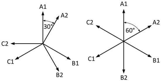
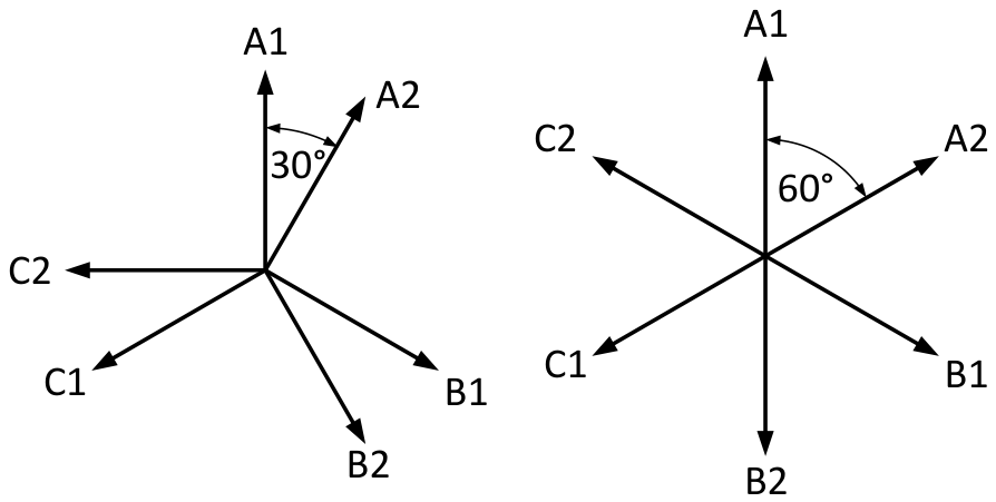
In this study, the six-phase SPM machine is considered an extension of the three-phase SPM baseline. From the converter perspective, it can be supplied by two three-phase voltage-source inverters using standard industrial power-electronic modules. A six-phase winding can be arranged in different ways depending on the phase-axis displacement between the two three-phase subsystems. In a symmetrical six-phase arrangement, the six phase axes are uniformly displaced by 60 electrical degrees. Alternatively, an asymmetric six-phase arrangement is obtained by shifting the two three-phase subsystems by 30 electrical degrees while maintaining a 120 electrical degree displacement within each subsystem, as illustrated in Figure 1.
Figure 1.
Asymmetric and symmetrical six-phase winding arrangements. In the symmetrical arrangement (right), the six phase axes are uniformly displaced by 60 electrical degrees. In the asymmetric arrangement (left) used in this study, the two three-phase subsystems are shifted by 30 electrical degrees.
The asymmetric arrangement is selected in this work because it provides a more favorable magnetomotive-force distribution than a duplicated three-phase winding and can reduce selected space-harmonic components. This is relevant in high-speed machines, where harmonic fields may contribute to rotor losses, torque ripple, vibration, and additional heating [30].
In the present comparison, the six-phase SPM machine is derived from the three-phase SPM topology by modifying the winding arrangement while keeping the same stator and rotor geometry. This allows the effect of changing from a three-phase to an asymmetric six-phase winding to be assessed without changing the magnetic circuit or rotor structure.
2.4. Material Selection
The materials selected for the comparative study are listed in Table 2. The listed prices are used only for a first-order estimate of active-material cost. Manufacturing costs are not included. Estimating manufacturing process costs reliably can be challenging at an early design stage. In contrast, active-material costs can be estimated directly from the calculated material masses and assumed unit prices, providing a consistent basis for the preliminary comparison of the investigated topologies. The same material assumptions apply to all topologies wherever possible, so the resulting comparison reflects topology-dependent behavior rather than different material choices. The selected materials represent industrially available solutions that are compatible with the intended power range, speed level, and cost-sensitive heat recovery application.
Table 2.
Active materials and assumed prices.
The stator and rotor cores are made of M235-35A non-oriented electrical steel. This material is selected as a practical compromise between electromagnetic performance, mechanical strength, availability, and cost. Although thinner laminations could reduce high-frequency core losses, a standard 0.35 mm steel grade is appropriate for a topology-screening study aimed at comparing machine concepts under common industrial assumptions. The relatively high allowable mechanical stress of this material is also important for the feasibility of the rotor at 30 krpm.
All candidate machines use copper for the stator windings.
Two permanent magnet materials are considered. NdFeB magnets provide high remanent flux density and high energy product, enabling high torque density, high power factor, and compact PM machine designs. However, they are expensive and sensitive to elevated temperatures, making thermal verification essential. Ferrite magnets provide a low-cost, rare-earth-free alternative. Their lower remanent flux density reduces torque density and power factor, but their higher thermal robustness can be advantageous in continuous high-speed operation. Their magnetic characteristics are temperature-dependent: the coercive force increases with temperature, while remanent flux density decreases.
For the induction machine, aluminum is used for the squirrel-cage rotor. This choice is made because aluminum has a lower density than copper, reducing centrifugal loading and rotor stress at high speed. Although copper cages can improve electrical performance at lower speeds, their higher mass density is less favorable for the investigated 30 krpm application.
For the SPM, IPM, and SynRM rotor configurations requiring circumferential reinforcement, carbon-fiber retaining sleeves are included to ensure rotor containment and mechanical integrity at high rotational speeds. Although primarily mechanical components, the sleeves also affect electromagnetic and thermal performance by increasing the effective air gap and modifying rotor heat transfer. These effects are included in the electromagnetic, thermal, and mechanical models.
The parameters of the carbon fiber sleeve material used for the mechanical simulations are given in Table 3.
Table 3.
Adopted material properties of the carbon-fiber-reinforced polymer (CFRP) retaining sleeves.
2.5. Topology Selection
The candidate topologies were selected to cover the principal electromagnetic torque-production mechanisms relevant to compact high-speed generation: permanent magnet excitation, reluctance torque, and induction torque. The comparison includes six machine configurations: a three-phase SPM machine, a six-phase SPM machine, an IPM machine with NdFeB magnets, an IPM machine with ferrite magnets, a SynRM, and an induction machine (Table 4).
Table 4.
Candidate generator topologies and main design considerations.
The selection is guided by the requirement that all topologies must be compatible with the same speed, voltage, cooling, and active-volume constraints. Wound-field synchronous generators are not considered, since rotor excitation windings and excitation hardware introduce additional mechanical and thermal complexity that is not favorable for the investigated compact high-speed class. The comparison therefore focuses on converter-interfaced machine types that can be implemented using realistic industrial manufacturing methods.
The three-phase SPM machine serves as a high-performance PM reference with a simple electromagnetic structure and high air-gap flux density. The six-phase SPM machine evaluates the influence of phase number and winding arrangement under unchanged magnetic geometry. The NdFeB IPM machine represents a high-performance buried-magnet topology with reluctance torque contribution and field-weakening capability. The ferrite IPM machine evaluates a lower-cost, rare-earth-free PM-assisted solution. The SynRM represents a magnet-free synchronous topology without rotor conductors, while the induction machine represents a mature asynchronous benchmark with a robust squirrel-cage rotor.
This topology set enables comparisons that distinguish electromagnetic capability from practical feasibility. The following sections therefore evaluate not only output power, efficiency, and power factor but also continuous thermal behavior, rotor mechanical stress, active-material mass, and active-material cost. The main geometrical and winding parameters of the investigated generator topologies are summarized in Appendix A, in Table A1.
3. Modeling and Evaluation Methodology
The six topologies defined in Section 2.5 were evaluated using the same modeling workflow. The purpose of the analysis was to obtain a comparable set of electromagnetic, thermal, mechanical, mass, and active material cost indicators. All machines were analyzed within the same voltage, speed, cooling, material, and active volume framework defined in Section 2.1. Topology-specific features, such as retaining sleeves, permanent magnets, and squirrel-cage conductors, were included where required by the corresponding machine design.
The numerical evaluation of the six generator topologies followed the procedure outlined below:
- The machine geometries, winding configurations, and material properties were defined according to the common design requirements.
- Electromagnetic models were constructed to evaluate generator performance under the prescribed voltage and current limits.
- Peak torque-speed and power-speed characteristics, efficiency maps, and power factor maps were calculated.
- The electromagnetic losses were used as inputs to the thermal models. Steady-state thermal envelope calculations were then performed to determine the continuous operating characteristics.
- Structural finite element analyses were carried out separately at the maximum rotational speed to assess rotor mechanical integrity.
- Finally, the electromagnetic, thermal, and mechanical results were combined with material mass and cost estimates to compare the six generator topologies.
3.1. Electromagnetic Finite Element Analysis
The electromagnetic performance was evaluated using two-dimensional transient magnetic finite element calculations that included rotor motion. The same electromagnetic post-processing procedure was applied to all machines. The simulations were used to obtain magnetic flux density distributions, line-to-line voltage waveforms, electromagnetic torque waveforms, torque ripple, torque-speed and power-speed characteristics, efficiency maps, power factor maps, and field-weakening capability. The main electromagnetic modeling and calculation settings used in Motor-CAD are summarized in Table 5.
Table 5.
Electromagnetic modeling and calculation settings.
Operating points were evaluated over the specified speed range up to 30 krpm. For the permanent magnet and reluctance machines, the stator current magnitude and current angle were varied within the common voltage constraint and design-specific current ranges. For the induction machine, the generator operating points were obtained by varying the slip and stator current within the corresponding constraints. The upper RMS phase-current bounds used for this exploration were 212 A for the three-phase SPM, NdFeB IPM, and induction machines, 106 A for the six-phase SPM machine, and 450 A for the ferrite IPM and SynRM designs. The current ranges for the ferrite IPM and SynRM designs were extended to investigate their achievable power given their lower power factors. These bounds defined the explored electromagnetic operating space. At each speed, the feasible operating points were post-processed to determine the peak electromagnetic capability and the operating points used for thermal evaluation. Continuous operating capability was subsequently determined through the coupled electromagnetic–thermal calculations described in Section 3.2. The actual RMS phase currents at each design’s maximum continuous power operating point are reported in Table 6.
Table 6.
Quantitative comparison of the continuous performance, mechanical characteristics and active-material cost of the six analyzed high-speed generator designs.
The electromagnetic model also provided the loss distribution used as input to the thermal model. The considered losses included stator copper loss, stator and rotor core losses, magnet losses, and, where applicable, rotor cage losses. The stator and rotor iron losses were evaluated using finite element-based loss maps, with an iron-loss build factor of 1.8 applied to both components. Additional AC winding losses were evaluated using the hybrid loss calculation method. The calculated losses were accounted for in the efficiency maps. Losses associated with PWM-induced voltage and current harmonics were not included in the simulations. The adopted comparison framework combined common voltage, speed, dimensional, and cooling constraints with design-specific current ranges and control variables. The objective was to evaluate the achievable continuous power, targeting approximately 100 kW, within the dimensional constraints of an IEC-standard housing and the permissible temperature limits of critical machine materials. Although alternative comparison criteria and topology-specific optimization approaches may lead to different performance rankings, the present methodology provides an application-oriented benchmark for the investigated designs rather than an assessment of the absolute maximum performance potential of each topology.
3.2. Thermal Analysis and Continuous Rating
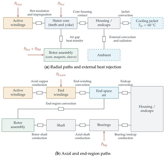
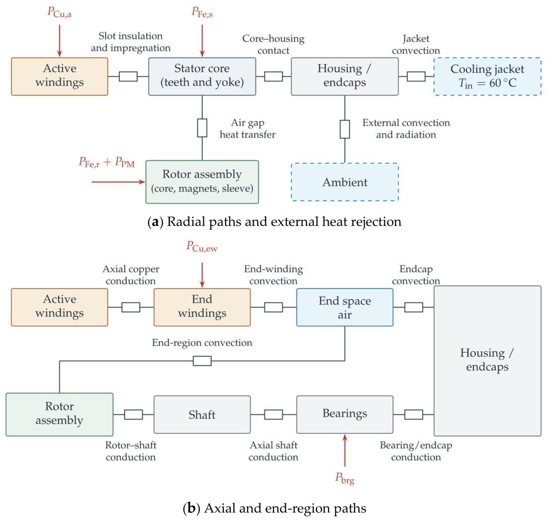
Thermal behavior was evaluated using a specialized software package for electrical machine thermal analysis [33], based on the lumped-parameter thermal network (LPTN) approach. Based on the specified machine geometry, winding configuration, material properties, and cooling conditions, the software automatically generates the thermal network and determines the corresponding thermal resistances and capacitances using appropriate analytical formulations and empirical heat-transfer correlations [34]. The number and arrangement of thermal nodes are therefore adapted to the specific geometry and construction of each generator topology investigated. As a representative example, the thermal network of the NdFeB IPM generator consists of 155 component nodes connected by 253 thermal-resistance connections. Figure 2 shows a simplified schematic of the principal heat-transfer paths: (a) radial paths and external heat rejection and (b) axial and end-region paths. The network accounts for both radial and axial heat-transfer paths. Radial heat transfer occurs primarily from the stator windings through the stator core and housing towards the cooling jacket, while heat generated in the rotor is transferred across the air gap towards the stator. Axial heat transfer is represented through the stator and rotor cores, shaft, and end winding regions.
Figure 2.
Simplified schematic of the principal heat-transfer paths in the NdFeB IPM generator: (a) radial paths and external heat rejection; (b) axial and end-region paths. Component boxes group multiple thermal nodes, and some components appear in both panels because their radial and axial heat-transfer paths are shown separately. Resistance symbols represent heat-transfer paths, and arrows indicate selected loss inputs.
The thermal model includes conduction, convection, and radiation, with convective heat-transfer coefficients determined using empirical correlations appropriate for the corresponding flow conditions, including rotating air gap flow [34,35]. A water-jacket cooling system using a 50/50 ethylene glycol–water (EGW) mixture at a coolant inlet temperature of 60 °C and an ambient temperature of 40 °C was considered for all investigated topologies. The coolant flow was set to 14 L/min.
The electromagnetic losses obtained from the finite element models were assigned to the corresponding machine regions, including the stator winding, stator core, rotor core, magnets, and rotor cage where applicable. Windage and bearing-friction losses were also included and were calculated analytically as functions of rotational speed. Retaining sleeves were included in the thermal model, while their eddy current losses were neglected. The same water-jacket cooling concept and housing constraints were applied to all topologies. The thermal model provided radial and axial temperature distributions and the maximum temperatures of the stator windings and relevant rotor components at the evaluated operating points.
The continuous operating capability was determined by coupling the electromagnetic and thermal calculations. For each topology, the losses corresponding to a candidate operating point were applied to the thermal network, and the steady-state temperature distribution was calculated. The coupled calculations were repeated until convergence using the predefined solver settings. The continuous output power at a given speed was then defined as the highest output power among the evaluated feasible operating points that satisfied the adopted thermal constraints. The adopted thermal limits were 200 °C for the stator windings, 180 °C for NdFeB magnets, 200 °C for ferrite magnets, and 200 °C for the rotor cage. In this way, the continuous torque-speed and power-speed characteristics account not only for electromagnetic capability but also for the location and magnitude of losses inside the machine.
3.3. Rotor Mechanical Analysis
Rotor mechanical integrity was assessed using finite element structural analysis at the maximum rotational speed of 30 krpm. The analysis included centrifugal loading from rotor rotation and the material properties of the rotor core, magnets, sleeves, inserts, and squirrel-cage conductors, where applicable. For sleeved rotor designs, the sleeve geometry and assembly preload were included in the structural model.
The maximum von Mises stress in the rotor laminations was used as the principal mechanical comparison quantity, since the rotor iron bridges, where present, were identified as the most mechanically critical regions. The adopted stress limit of 460 MPa was taken from the manufacturer’s datasheet for the rotor lamination steel and was applied specifically to the rotor laminations. The datasheet value was used directly, without an additional safety factor or adjustment for the rotor operating temperature. Stresses in other rotor components were also examined, but the reported quantitative comparison focuses on the rotor laminations. The 460 MPa limit should therefore not be interpreted as a universal allowable stress for all rotor components. Comprehensive mechanical validation of the selected design would additionally require assessment of temperature-dependent material properties and appropriate material-specific failure criteria and safety factors, including consideration of the anisotropic behavior of CFRP retaining sleeves. Stress distributions were also examined to identify mechanically sensitive regions, such as magnet-retention areas, flux barriers, bridges, retaining sleeves, and squirrel-cage slots.
3.4. Comparison Indicators
The final comparison was based on electromagnetic, thermal, mechanical, mass, and active-material-cost indicators. The electromagnetic indicators included maximum RMS phase current, current density, maximum torque, corner speed, maximum power, maximum continuous power, continuous power at 30 krpm, continuous low-speed torque limit, maximum efficiency, average efficiency, maximum power factor, and average power factor. The thermal indicators were the maximum stator and rotor temperatures obtained from the steady-state thermal calculations. The mechanical indicator was the maximum von Mises stress in the rotor laminations at 30 krpm.
The material-related indicators included copper mass, iron mass, aluminum mass, magnet mass, and estimated active-material cost. The active-material cost was calculated from the material masses and the representative unit prices listed in Table 2. This estimate is intended for relative comparison only and does not include manufacturing.
The resulting data set allows the six generator topologies to be compared on a common design basis. The comparison therefore identifies not only the machines with the highest electromagnetic output but also those that satisfy the adopted continuous thermal limits and rotor-lamination stress criterion.
4. Multiphysics Analysis of High-Speed Generator Topologies
This section presents the electromagnetic, thermal, and mechanical results for the six analyzed generator topologies. The voltage and torque waveforms, as well as the thermal distributions, are evaluated at the operating point corresponding to the maximum continuous output power of the respective topology. The mechanical stress plots are evaluated at the maximum rotational speed of 30 krpm.
4.1. Three-Phase SPM Machine
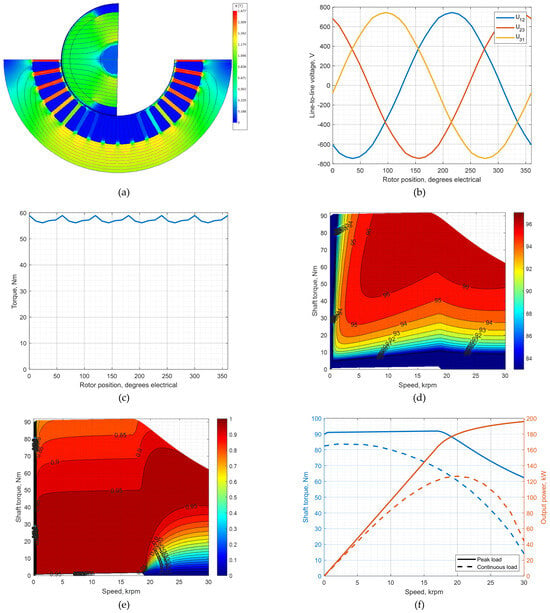
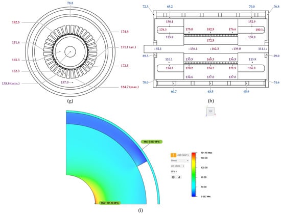
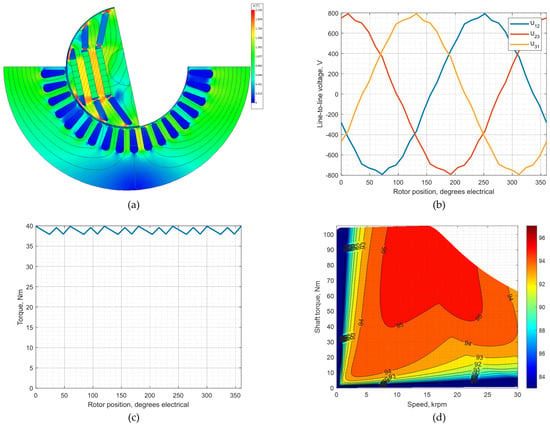
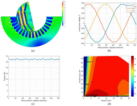
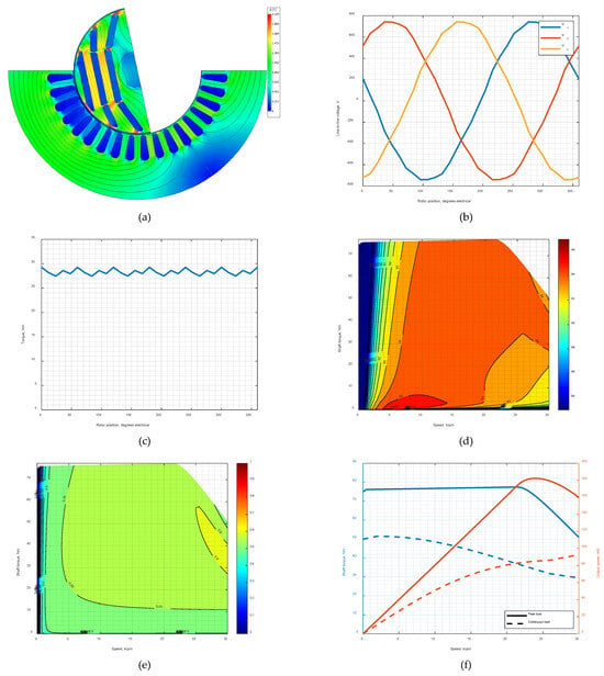
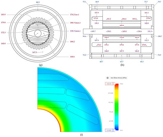
The three-phase SPM machine is used as the reference permanent magnet topology. The rotor contains surface-mounted NdFeB magnets retained by a 1 mm carbon-fiber sleeve to withstand centrifugal loading at high speed. The results are shown in Figure 3.
Figure 3.
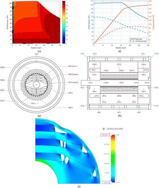
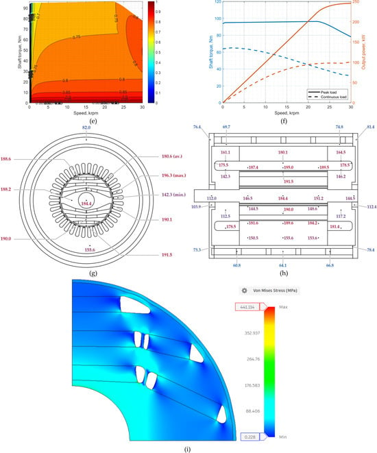
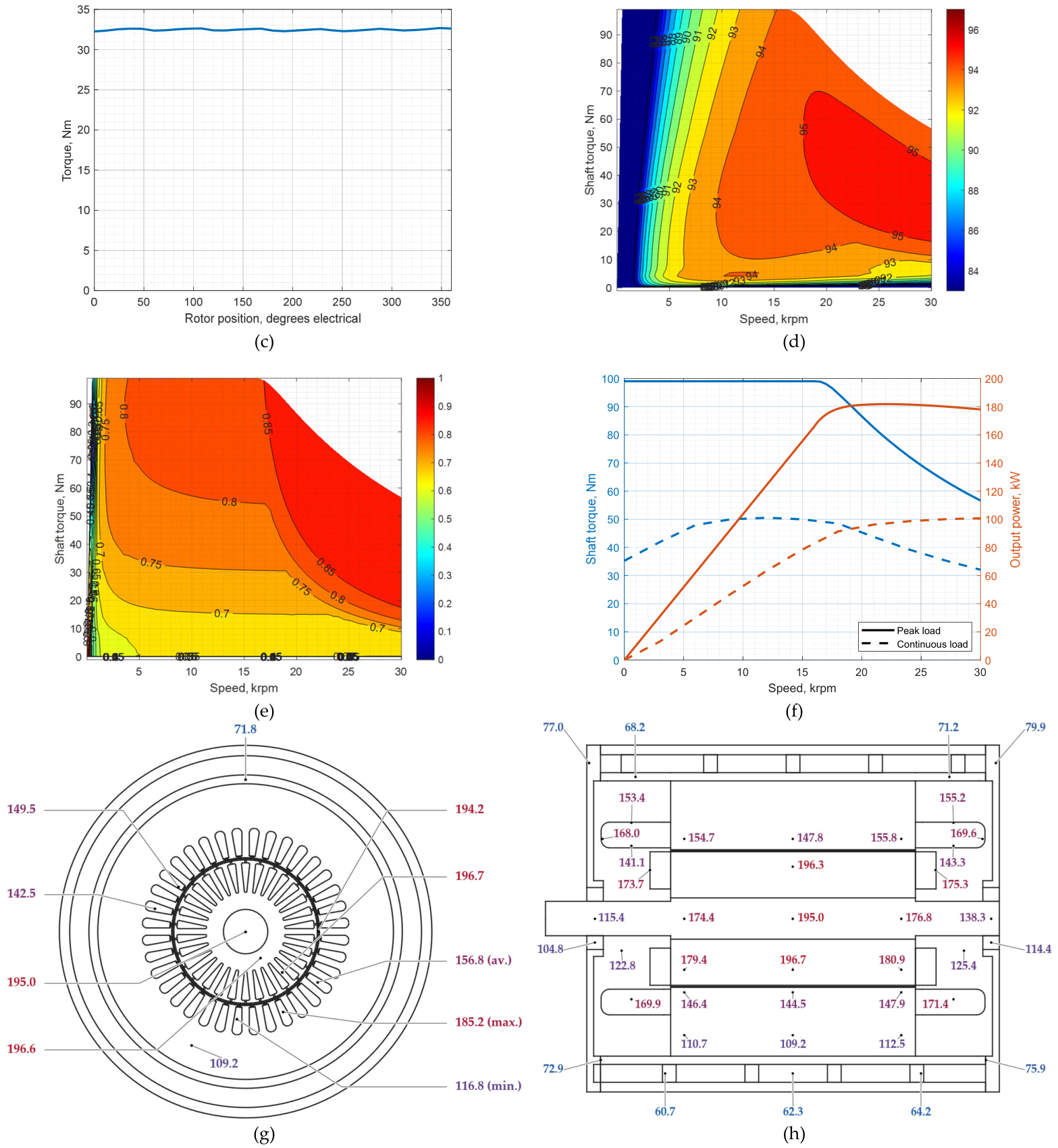
Multiphysics results for the three-phase SPM machine: (a) magnetic flux-density distribution under load; (b) line-to-line voltage waveform; (c) electromagnetic torque waveform; (d) efficiency map; (e) power factor map; (f) peak and continuous torque/power characteristics; (g) radial temperature distribution; (h) axial temperature distribution; and (i) rotor von Mises stress at 30 krpm. In panels (g,h), labels indicate selected component temperatures in °C. The abbreviations min., av., and max. denote the minimum, average, and maximum stator winding temperatures, respectively. Winding statistics are displayed at representative positions for readability.
The maximum continuous output power is 125 kW and occurs at 20 krpm, with a phase RMS current of 147.4 A and a current advance angle of 164.27 electrical degrees. At the maximum speed of 30 krpm, the continuous output power decreases to 44.1 kW, indicating the limited high-speed field-weakening capability of the SPM topology within the adopted voltage limit.
At the maximum continuous power operating point, the maximum stator winding temperature is approximately 185 °C, while the maximum rotor magnet temperature is approximately 172.5 °C. The rotor stress analysis at 30 krpm gives a maximum von Mises stress in the rotor laminations of 181.5 MPa, which remains well below the adopted allowable stress of 460 MPa. The design therefore satisfies the adopted rotor-lamination stress criterion at 30 krpm, but its continuous power capability at the target maximum speed is limited.
4.2. Six-Phase SPM Machine
The six-phase SPM machine is derived from the three-phase SPM baseline by modifying only the winding arrangement. The stator and rotor geometry are unchanged, and the winding is an asymmetric six-phase winding with a 30 electrical degree shift between corresponding phases of the two three-phase subsystems. For the previously specified configuration of 36 stator slots and two rotor poles, the six-phase variant features a single-layer concentric winding with three slots per pole per phase, in contrast to the double-layer lap winding with six slots per pole per phase used in the three-phase machine.
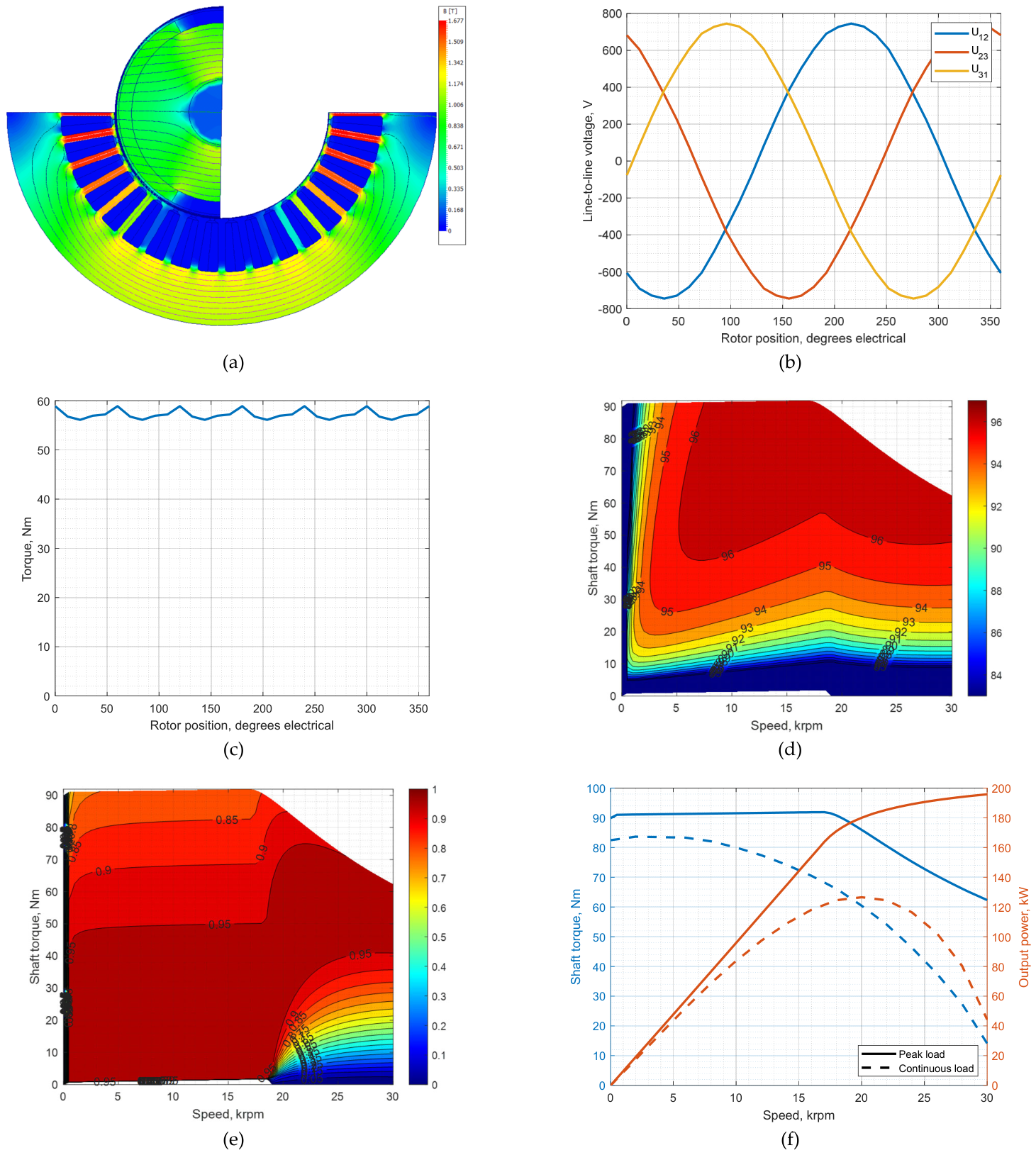
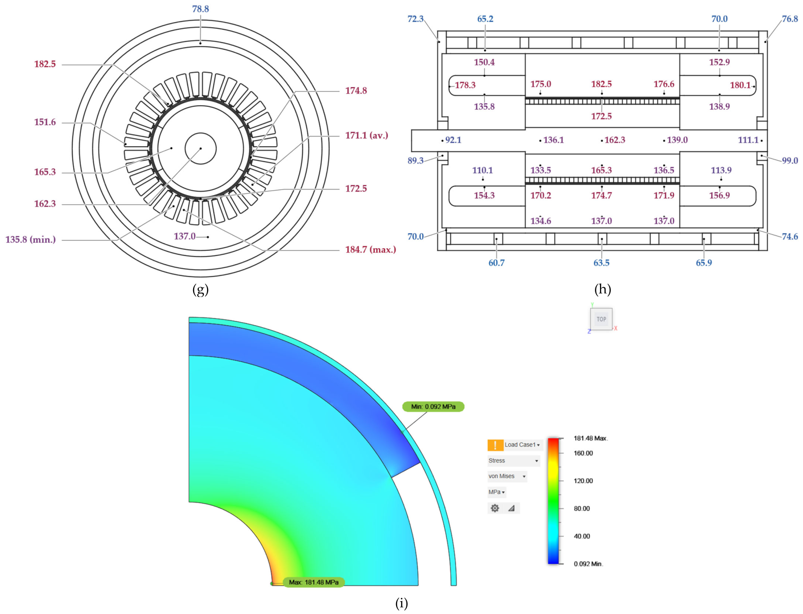
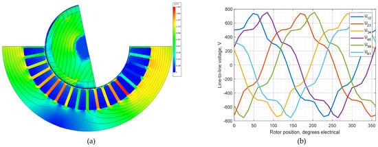
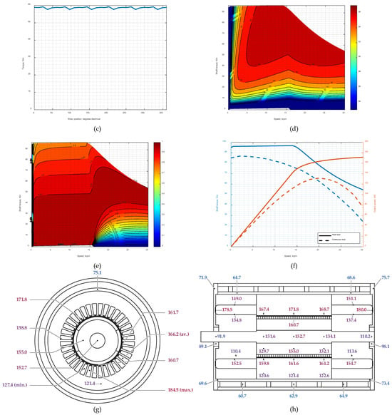
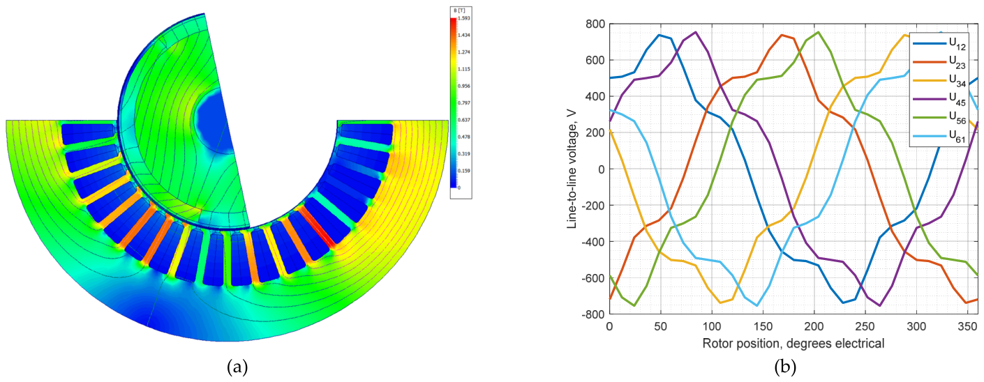
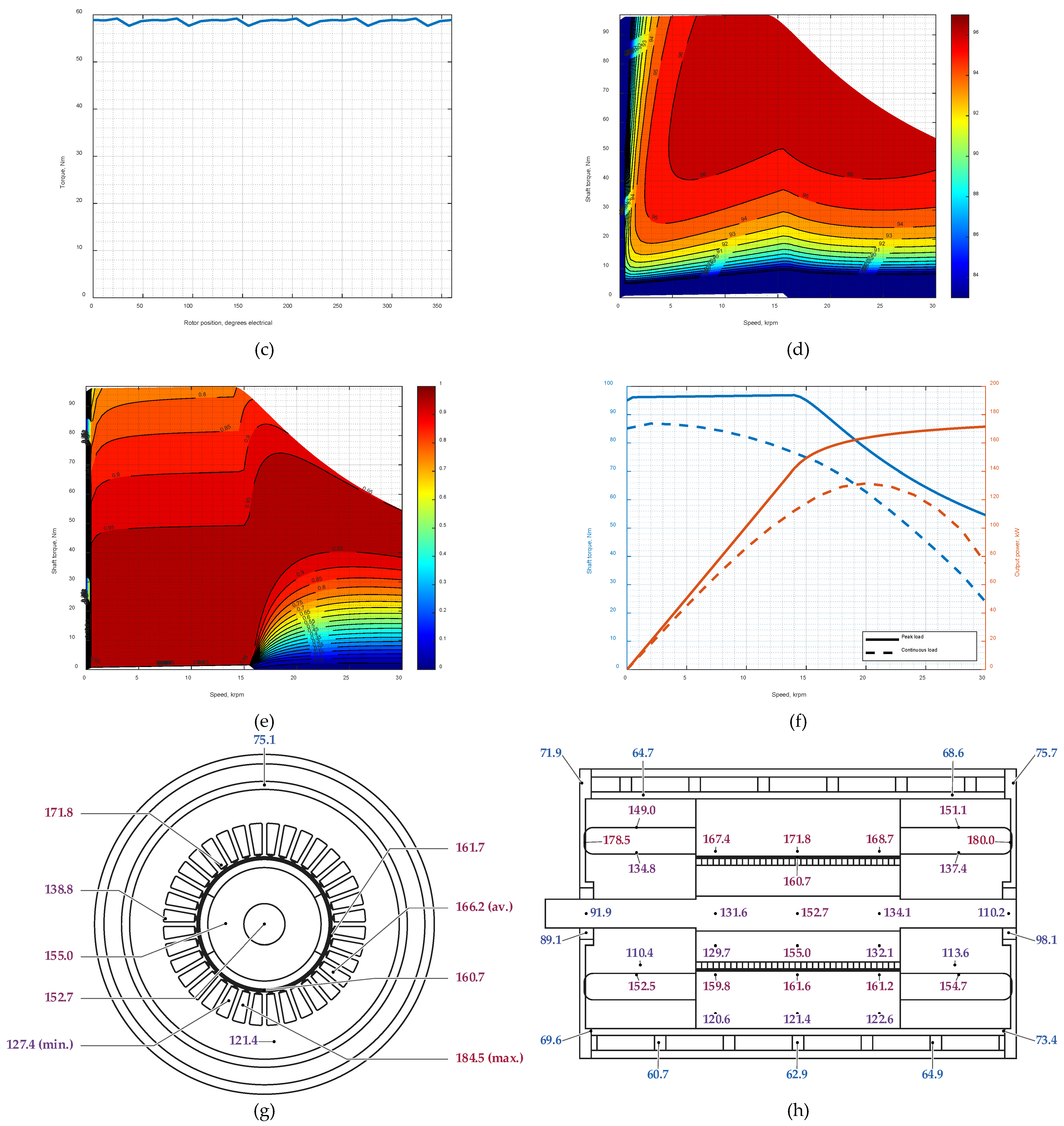
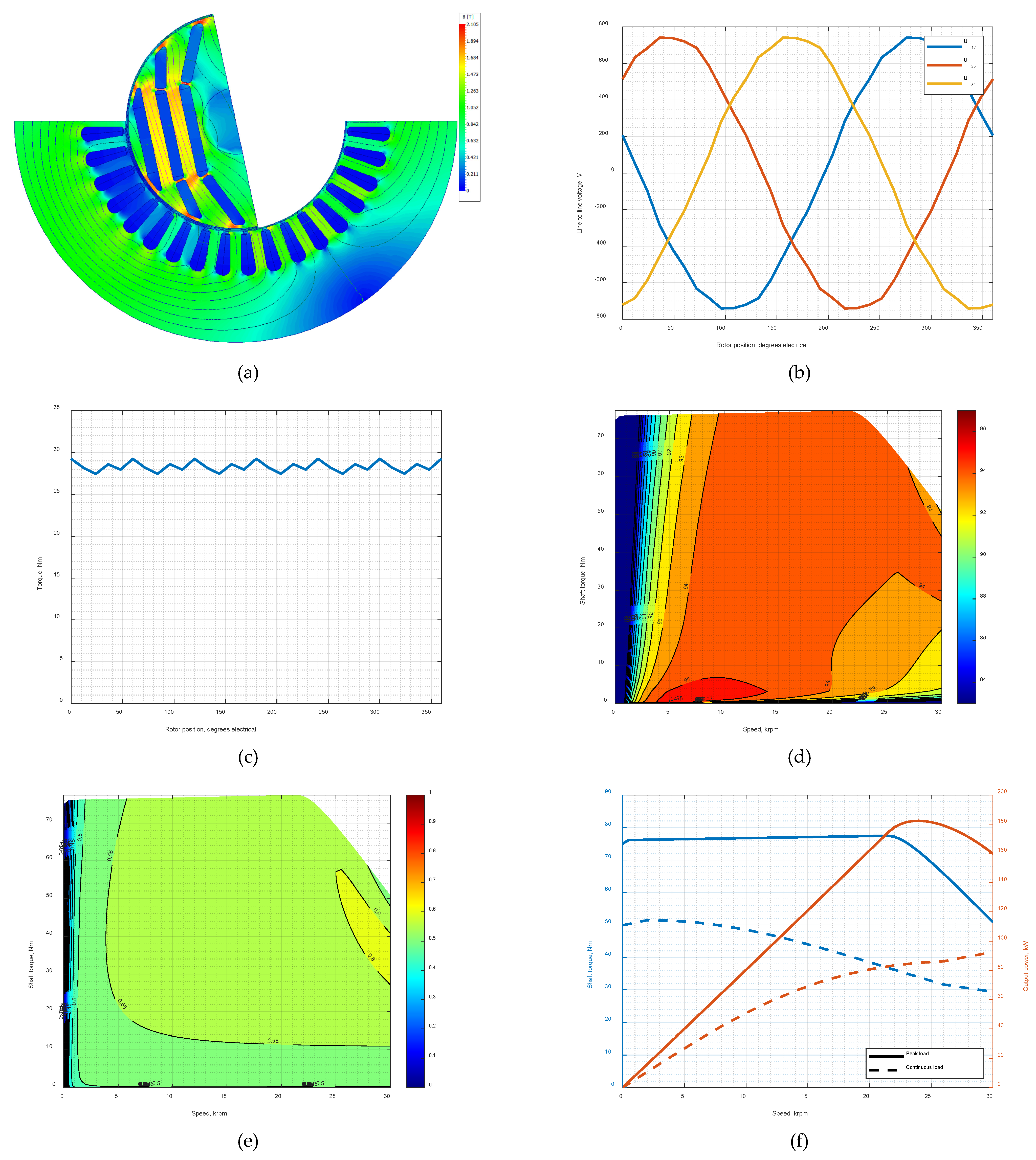
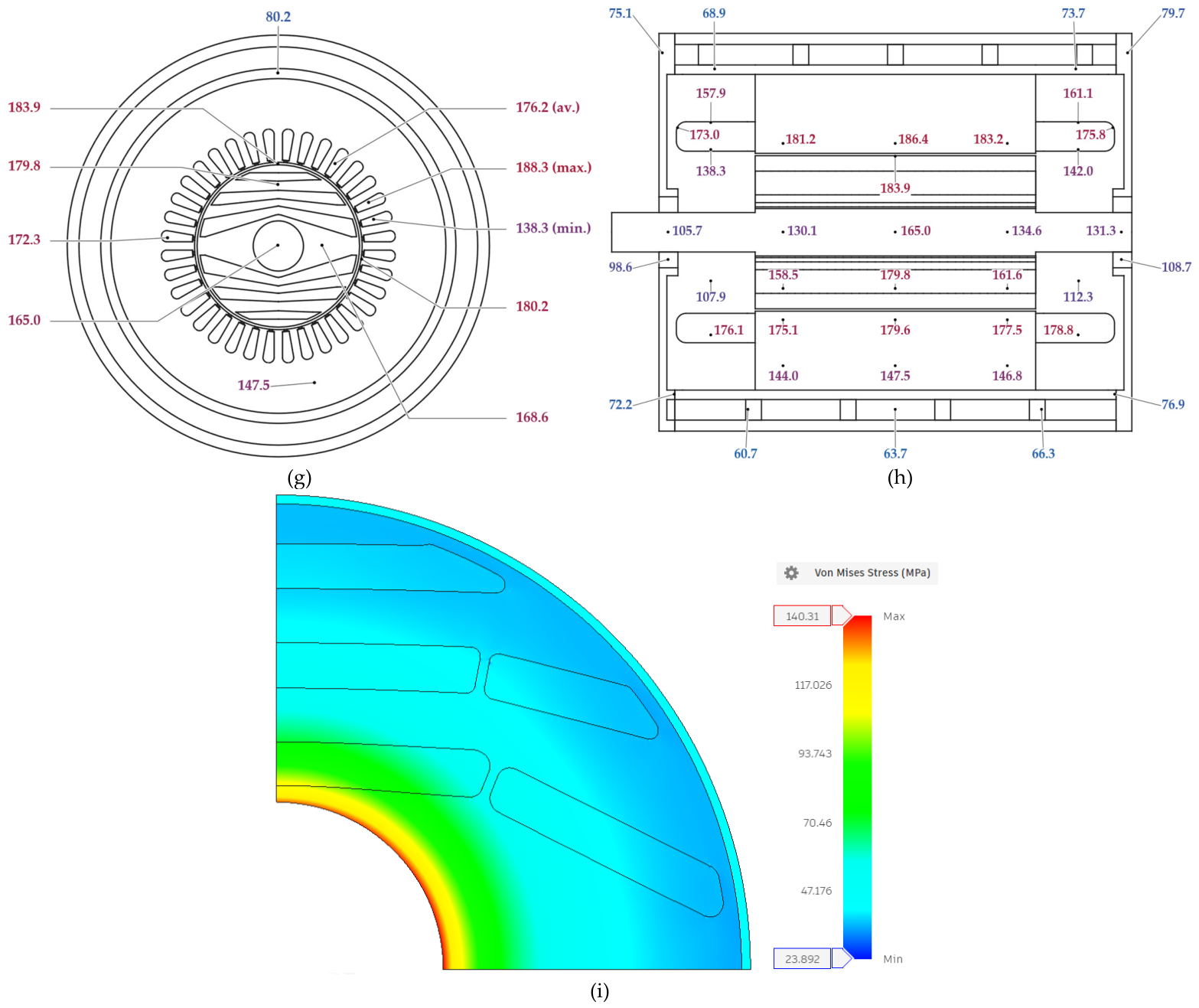
The simulation results are shown in Figure 4. Since the rotor geometry is unchanged, the mechanical stress result is identical to that of the three-phase SPM machine shown in Figure 3i. The maximum continuous output power is 131.6 kW at 20 krpm. The voltage and torque waveforms are shown at this operating point, corresponding to a phase current of 82 A and a current advance angle of 143.31 electrical degrees.
Figure 4.
Multiphysics results for the six-phase SPM machine: (a) magnetic flux-density distribution under load; (b) line-to-line voltage waveform; (c) electromagnetic torque waveform; (d) efficiency map; (e) power factor map; (f) peak and continuous torque/power characteristics; (g) radial temperature distribution; and (h) axial temperature distribution. In panels (g,h), labels indicate selected component temperatures in °C. The abbreviations min., av., and max. denote the minimum, average, and maximum stator winding temperatures, respectively. Winding statistics are displayed at representative positions for readability.
Compared with the three-phase SPM machine, the six-phase variant provides higher continuous output power at the maximum speed. At 30 krpm, the continuous output increases from 44.1 kW to 75.0 kW. However, the loaded line-to-line voltage waveform is more distorted than in the three-phase case, with the total harmonic distortion (THD) increasing from 0.73% to 14.21%. The six-phase machine exhibits a lower peak-to-peak torque ripple of 1.52 Nm, compared with 2.75 Nm for the three-phase machine. Expressed relative to the respective average torque values, the torque ripple decreases from 4.80% to 2.59%, corresponding to a reduction of approximately 46.2%, although at the expense of considerably higher voltage harmonic distortion. The thermal behavior remains similar in the stator, with a maximum winding temperature of approximately 185 °C, while the maximum rotor temperature decreases to 160.7 °C. The six-phase SPM machine therefore improves high-speed continuous power capability relative to the three-phase SPM design, but it remains below the 100 kW target at 30 krpm and adds converter and control complexity.
4.3. IPM Machine with NdFeB Magnets
The NdFeB IPM topology uses buried magnets in the central rotor barriers and non-magnetic stainless-steel 304 inserts in the side barriers. A 1.0 mm carbon-fiber sleeve with an assembly preload of 10 MPa is included to improve rotor integrity at high speed.
The results are shown in Figure 5. The NdFeB IPM machine can continuously deliver approximately 90 kW over the 20–25 kRPM speed range and approximately 81.8 kW at 30 krpm. The maximum continuous power operating point is obtained at a phase current of 99.8 A and a current advance angle of 124.21 electrical degrees. The machine exhibits a high power factor at elevated speeds, which is favorable for operation within the voltage constraint.
Figure 5.
Multiphysics results for the IPM machine with NdFeB magnets: (a) magnetic flux-density distribution under load; (b) line-to-line voltage waveform; (c) electromagnetic torque waveform; (d) efficiency map; (e) power factor map; (f) peak and continuous torque/power characteristics; (g) radial temperature distribution; (h) axial temperature distribution; and (i) rotor von Mises stress at 30 krpm. In panels (g,h), labels indicate selected component temperatures in °C. The abbreviations min., av., and max. denote the minimum, average, and maximum stator winding temperatures, respectively. Winding statistics are displayed at representative positions for readability.
Thermally, this topology gives the lowest rotor temperature among the analyzed machines, with a maximum rotor temperature of approximately 158.1 °C. The maximum stator winding temperature is approximately 182 °C, which is also among the lowest values obtained. This thermal behavior is favorable for reducing demagnetization risk in the NdFeB magnets.
From a mechanical perspective, the designed rotor satisfies the adopted rotor-lamination stress criterion at 30 krpm. The maximum von Mises stress in the rotor laminations is approximately 396.9 MPa, remaining below the 460 MPa limit. The available stress margin is moderate, so the rotor-bridge geometry, sleeve fit, and insert material properties remain important design parameters for further optimization.
4.4. IPM Machine with Ferrite Magnets
The ferrite IPM topology is included as a rare-earth-free PM-assisted alternative to the NdFeB IPM design. Ferrite magnets have a lower remanent flux density and energy product than NdFeB magnets, which generally reduces air-gap flux density, torque density, and power factor. However, their lower material cost and reduced rare-earth dependence make them attractive for cost-sensitive applications. In the analyzed design, ferrite magnets are placed in all rotor barriers.
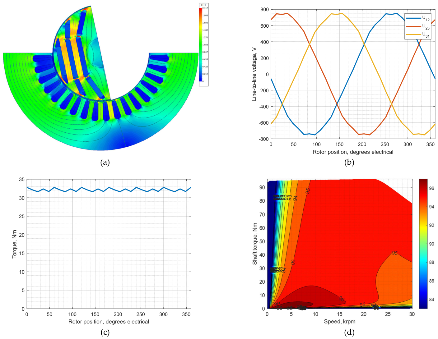
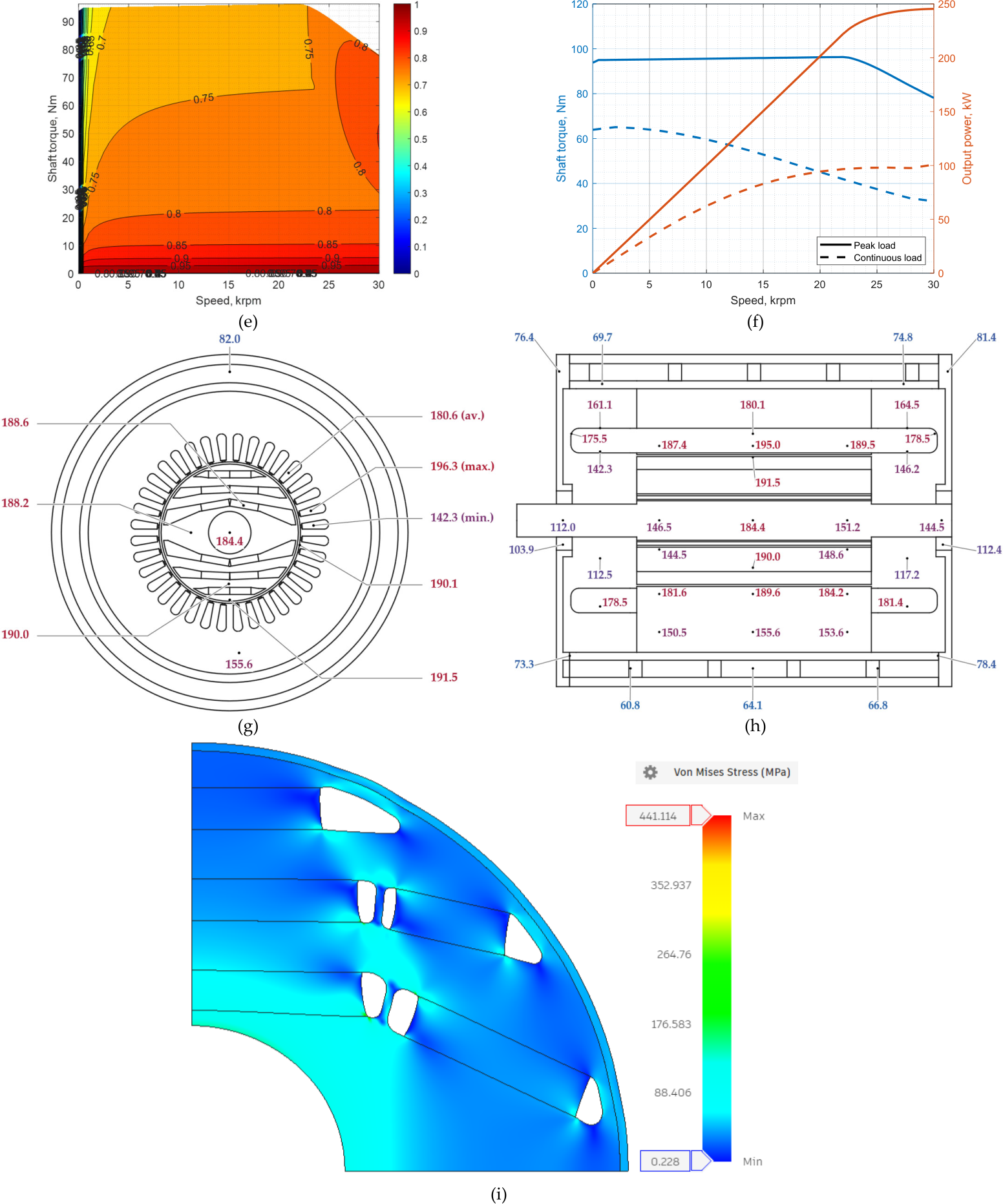
The results are shown in Figure 6. The ferrite IPM machine can operate continuously at approximately 90 kW from 18 krpm upwards, and the maximum continuous output power of 100.8 kW is reached at 30 krpm. At this operating point, phase current is 142.2 A, and the current advance angle is 126.82 electrical degrees. The efficiency map shows high efficiency over a broad operating region, while the power factor is lower than that of the NdFeB IPM machine.
Figure 6.
Multiphysics results for the IPM machine with ferrite magnets: (a) magnetic flux-density distribution under load; (b) line-to-line voltage waveform; (c) electromagnetic torque waveform; (d) efficiency map; (e) power factor map; (f) peak and continuous torque/power characteristics; (g) radial temperature distribution; (h) axial temperature distribution; and (i) rotor von Mises stress at 30 krpm. In panels (g,h), labels indicate selected component temperatures in °C. The abbreviations min., av., and max. denote the minimum, average, and maximum stator winding temperatures, respectively. Winding statistics are displayed at representative positions for readability.
The main limitation of this topology is thermal loading. The maximum stator winding temperature reaches approximately 196.3 °C, which is the highest value among the analyzed designs, while the maximum rotor temperature is approximately 191.5 °C. The ferrite IPM machine therefore meets the target continuous power at 30 krpm, but the winding insulation system, magnet thermal capability, and cooling design require particular attention.
The rotor also satisfies the adopted rotor-lamination stress criterion at 30 krpm. With the carbon-fiber retaining sleeve included, the maximum von Mises stress in the rotor laminations is approximately 441.1 MPa, remaining below the 460 MPa limit. The ferrite IPM rotor shows a relatively small lamination-stress margin of about 4.1% relative to the 460 MPa limit at 30 krpm, indicating that additional mechanical verification is needed before prototype manufacture. In particular, manufacturing tolerances, material property variations, thermal effects, and transient overspeed conditions should be considered. Increasing the retaining sleeve preload may, within a certain range, reduce the peak lamination stress at maximum speed and thereby increase this margin. However, higher preload also increases assembly-induced stresses at standstill and sleeve loading and may make manufacturing and assembly more demanding. Preload adjustment therefore cannot reduce rotor stress indefinitely. Selecting it requires assessing both the rotor laminations and the sleeve over the relevant speed and temperature range, including standstill. Further optimization should therefore consider both rotor-geometry refinement and sleeve-preload adjustment to increase the mechanical margin while maintaining acceptable electromagnetic performance and manufacturability. Detailed tolerance analysis and appropriate overspeed testing would be required before operational deployment.
4.5. Synchronous Reluctance Machine
The SynRM topology is included as a magnet-free synchronous alternative. For comparability with the IPM designs, the rotor is derived from the same general barrier concept, but the permanent magnets are omitted. Non-magnetic stainless-steel 304 inserts are placed in the flux barriers, and a carbon-fiber sleeve is added to improve mechanical integrity at high speed. This reinforced rotor configuration preserves the magnet-free character of the machine while avoiding unsupported slender rotor segments.
The results are shown in Figure 7. The analyzed SynRM reaches a continuous output power of approximately 92.4 kW at 30 krpm. At this operating point, the RMS phase current is 155.9 A, and the current advance angle is 117.7 electrical degrees. The continuous-power curve is still increasing at the upper boundary of the investigated speed range, but operation above 30 krpm was not analyzed because it lies outside the specified application envelope.
Figure 7.
Multiphysics results for the synchronous reluctance machine: (a) magnetic flux-density distribution under load; (b) line-to-line voltage waveform; (c) electromagnetic torque waveform; (d) efficiency map; (e) power factor map; (f) peak and continuous torque/power characteristics; (g) radial temperature distribution; (h) axial temperature distribution; and (i) rotor von Mises stress at 30 krpm. In panels (g,h), labels indicate selected component temperatures in °C. The abbreviations min., av., and max. denote the minimum, average, and maximum stator winding temperatures, respectively. Winding statistics are displayed at representative positions for readability.
Compared with the ferrite IPM machine, the absence of ferrite magnets reduces the continuous output power at 30 krpm by approximately 8 kW in this design family. Nevertheless, the result shows that a reinforced magnet-free rotor can achieve substantial continuous power under the adopted high-speed constraints. The stator and rotor temperatures are mid-range among the analyzed machines, with maximum values of approximately 188.3 °C and 183.9 °C, respectively. Since the rotor contains no permanent magnets or excitation winding, the main rotor-related concern is mechanical integrity rather than demagnetization.
The mechanical analysis confirms that the SynRM rotor satisfies the adopted rotor-lamination stress criterion at 30 krpm. The maximum von Mises stress in the rotor laminations is approximately 140.3 MPa, well below the 460 MPa limit.
4.6. Induction Machine
The induction machine is included as a mature asynchronous benchmark with a mechanically robust squirrel-cage rotor and no permanent magnets. In high-speed generator operation, its main challenge is rotor loss, since slip-related cage losses are generated directly in the rotating structure and can increase rotor temperature. The present design uses aluminum for the squirrel cage to reduce rotor mass and centrifugal loading compared with a copper cage, although the optimal cage material depends on the electromagnetic, thermal, and mechanical design objectives.
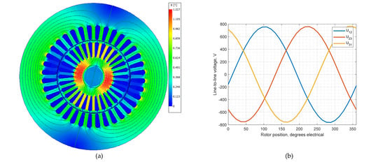
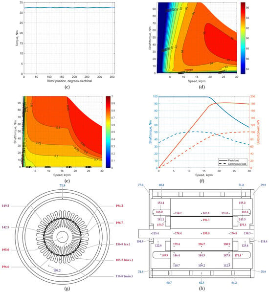
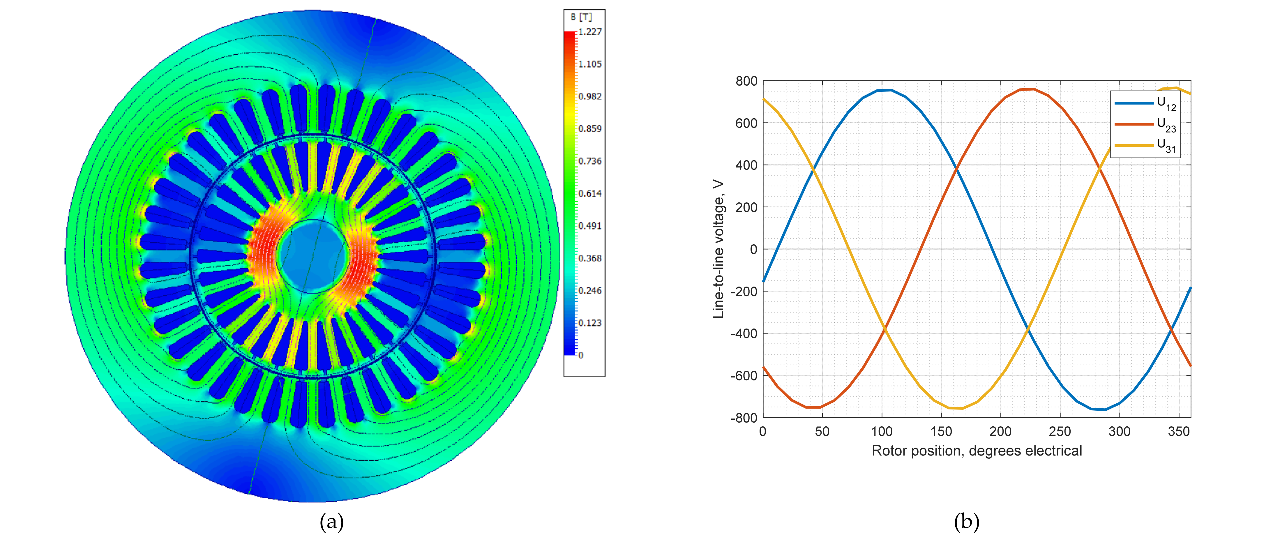
The results are shown in Figure 8. The maximum continuous-power operating point occurs at 30 krpm, with an RMS stator current of 119.0 A, a stator frequency of 496.28 Hz, and a slip of −0.8%, consistent with generator operation. Although this slip value may appear relatively small, it corresponds to a rotor current frequency of about 4 Hz because of the high stator electrical frequency. For comparison, the same rotor current frequency would correspond to a slip of 8% at a stator frequency of 50 Hz. The aluminum rotor bars have a depth of 20 mm, and the skin effect was taken into account in the electromagnetic simulations. The analyzed induction machine reaches approximately 100.7 kW in continuous operation at the maximum speed. The simulated torque waveform shows low torque ripple compared with the other topologies.
Figure 8.
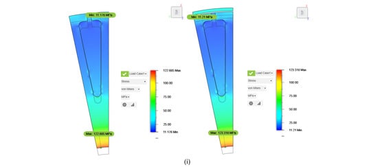
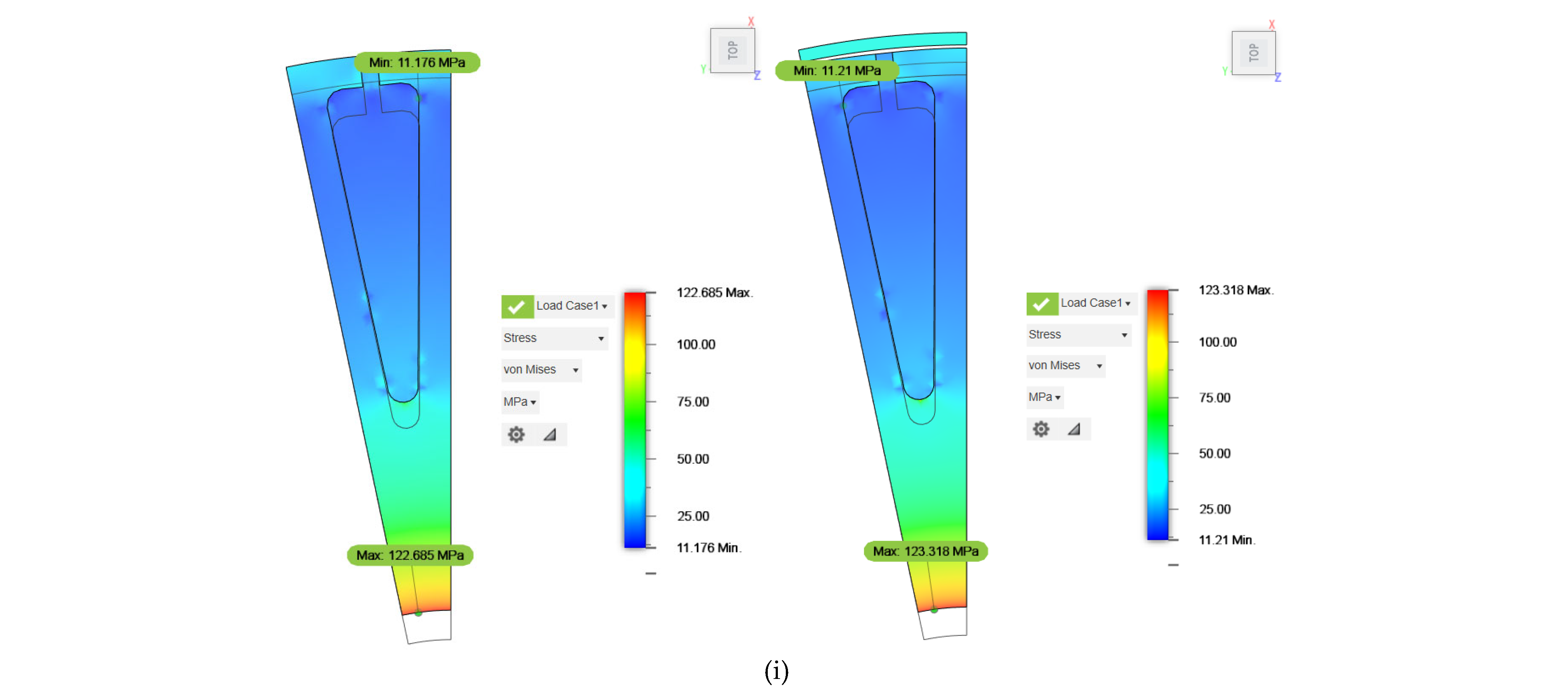
Multiphysics results for the induction machine: (a) magnetic flux-density distribution under load; (b) line-to-line voltage waveform; (c) electromagnetic torque waveform; (d) efficiency map; (e) power factor map; (f) peak and continuous torque/power characteristics; (g) radial temperature distribution; (h) axial temperature distribution; and (i) rotor von Mises stress of the rotor without (left) and with (right) a carbon-fiber sleeve at 30 krpm. In panels (g,h), labels indicate selected component temperatures in °C. The abbreviations min., av., and max. denote the minimum, average, and maximum stator winding temperatures, respectively. Winding statistics are displayed at representative positions for readability.
The principal limitation of the induction machine is rotor temperature. The maximum rotor temperature is approximately 196.7 °C, the highest value among the investigated designs, and is mainly associated with rotor cage losses.
The induction machine rotor has the lowest calculated maximum von Mises stress in the rotor laminations among the investigated designs. At 30 krpm, this stress is approximately 122.7 MPa, well below the adopted 460 MPa limit. The additional carbon-fiber sleeve has little effect on the maximum lamination stress in this design. The induction machine therefore offers a favorable lamination-stress margin under the analyzed conditions, while rotor thermal loading remains its main design concern.
5. Comparative Assessment of High-Speed Generator Topologies
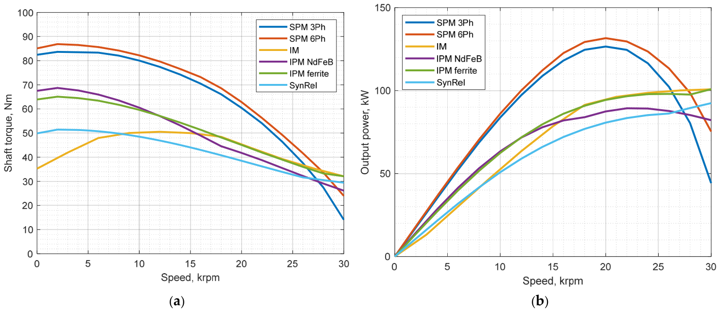
Figure 9 and Table 6 compare the six generator topologies using the electromagnetic, thermal, mechanical, mass, and active-material-cost indicators from the preceding sections. Figure 9 highlights the continuous torque-speed and power-speed capability of each design, while Table 6 summarizes the main quantitative results within the common design envelope. Additional electromagnetic performance indicators, efficiency and power factor map statistics, and active-material masses are provided in Table A3. The maximum and average efficiency and power factor values presented in Table A3 correspond to the highest values and arithmetic means, respectively, across all evaluated operating points in the corresponding efficiency and power factor maps. The comparison should be interpreted as a topology-screening assessment rather than as a final optimization result. The active-material cost includes only the copper, iron, aluminum, and magnet materials listed in Table 2 and is therefore used solely as a relative indicator.
Figure 9.
Comparison of the continuous torque-speed and power-speed characteristics of the six analyzed generator topologies: (a) continuous torque-speed characteristics and (b) continuous power-speed characteristics.
Continuous power at maximum speed is the most relevant power indicator for the present application. Although the three-phase and six-phase SPM machines achieve the highest maximum continuous powers (125.0 kW and 131.6 kW, respectively), their continuous output at 30 krpm decreases to 44.1 kW and 75.0 kW. This indicates that their maximum continuous capability occurs at intermediate speeds and that their power retention at the upper end of the speed range is limited by the voltage and field-weakening constraints. In contrast, the ferrite IPM and induction machines reach 100.8 kW and 100.7 kW at 30 krpm, respectively, providing the closest match to the targeted 100 kW class at the maximum operating speed. The SynRM reaches 92.4 kW at 30 krpm, while the NdFeB IPM reaches 81.8 kW.
The power-factor results further differentiate the topologies from the converter perspective. The NdFeB IPM machine exhibits the highest average power factor, 0.916, which is favorable for converter utilization and current demand. The SPM machines also show favorable power-factor behavior, with an average value of 0.836, while the ferrite IPM and induction machines reach average values of 0.832 and 0.803, respectively. The SynRM has the lowest average power factor (0.511) and requires the highest RMS current among the investigated machines. Although it is attractive as a magnet-free topology, this low power factor would increase the apparent-power rating and current stress of the converter.
Table A2 presents the modeled loss components at each design’s maximum continuous-power operating point. These operating points occur at different speeds and output powers. Stator iron losses are the largest individual loss component in all five synchronous designs. In the induction machine, stator winding losses are the largest individual component, while rotor cage and stray losses also contribute substantially to the total losses. Rotor cage losses are generated in the rotating structure, which has different heat-removal paths from the stator. The loss distribution and the thermal paths from each component must therefore be considered alongside efficiency when assessing continuous operating capability.
The thermal results show that different topologies are limited by different heat sources. The ferrite IPM machine has the highest stator temperature, 196.3 °C, indicating that the winding insulation system and cooling arrangement are critical for this design. The induction machine has the highest rotor temperature, 196.7 °C, mainly because slip-related cage losses are generated in the rotating structure. The NdFeB IPM machine has the lowest rotor temperature, 158.1 °C, which is favorable for magnet thermal loading and demagnetization margin. The SPM and SynRM designs exhibit intermediate thermal behavior.
The mechanical comparison shows that the maximum von Mises stress in the rotor laminations remains below the adopted limit of 460 MPa at 30 krpm for all analyzed designs. However, the margins relative to this limit differ significantly. The ferrite IPM rotor reaches 441.1 MPa, corresponding to a small lamination-stress margin, while the NdFeB IPM rotor reaches 396.9 MPa. The three-phase and six-phase SPM rotors reach 181.5 MPa, the SynRM rotor reaches 140.3 MPa, and the induction-machine rotor reaches 122.7 MPa. The induction machine therefore has the largest margin relative to the adopted lamination-stress limit, whereas the ferrite IPM requires particular attention to rotor mechanical refinement and manufacturing tolerances.
The material and cost indicators clearly distinguish between rare-earth and rare-earth-free solutions. The NdFeB SPM and NdFeB IPM machines have the highest active-material costs, 408.2 EUR and 350.8 EUR, respectively, mainly because of the NdFeB magnets. The ferrite IPM, SynRM, and induction-machine designs have substantially lower active-material costs, 135.8 EUR, 125.8 EUR, and 131.5 EUR, respectively. The SynRM also has the lowest total active mass, although this advantage must be weighed against its low power factor and high current requirement.
The comparison is based on numerical predictions without experimental validation, and a separate mesh- and time-step-independence study was not performed. The influence of three-dimensional electromagnetic effects not resolved by the adopted modeling approach, neglected retaining-sleeve eddy-current losses, and PWM-related losses on the predicted continuous ratings has not been quantified. These uncertainties may affect the relative ranking of designs with similar predicted performance. The results therefore support initial candidate selection for further optimization and validation, while closely matched outcomes should be interpreted cautiously.
Taken together, the results show that the preferred topology depends on the dominant design priority. For an application prioritizing approximately 100 kW of continuous output at 30 krpm and low active-material cost, the ferrite IPM and induction machines are the most promising starting points. Their limiting factors differ: the ferrite IPM requires further reduction in stator temperature and improved rotor stress margin, whereas the induction machine requires improved rotor heat removal. The NdFeB IPM is attractive where a high power factor and low rotor temperature justify the higher magnet cost. The SynRM is a credible rare-earth-free alternative if its low power factor and higher converter-current requirement are acceptable. The SPM topologies remain attractive when high continuous power at intermediate speeds is more important than maintaining the nominal power level at 30 krpm.
6. Conclusions
This study compared six two-pole high-speed generator topologies within a common design envelope defined by a maximum speed of 30 krpm, a 750 V DC-link, water-jacket cooling, and an IEC 132 housing. The comparison combined transient electromagnetic finite element analysis, thermal-network calculations, rotor structural analysis, and active-material cost estimation. The results show that no topology dominates across all electromagnetic, thermal, mechanical, and material-cost criteria. Peak electromagnetic performance alone is therefore insufficient for topology selection in compact high-speed generator systems.
The three-phase and six-phase SPM machines achieved the highest maximum continuous powers, but their continuous output at 30 krpm remained below the targeted 100 kW class. The ferrite IPM and induction machines most closely matched the required continuous power at maximum speed and had substantially lower active-material cost than the NdFeB-based machines. The ferrite IPM is attractive as a rare-earth-free PM-assisted topology, but its stator temperature and rotor stress margin are critical. The induction machine combines low rotor-lamination stress with low active-material cost, but rotor heating from squirrel-cage losses remains its main thermal limitation. The NdFeB IPM offers a high power factor and low rotor temperature at a higher active-material cost, while the SynRM provides a low-cost, magnet-free alternative with a reduced power factor and higher converter current demand.
At the present screening level, the maximum von Mises stress in the rotor laminations remained below the adopted 460 MPa limit at 30 krpm for all six designs. Nevertheless, further verification is required before prototype manufacture, including overspeed, fatigue, rotordynamic, sleeve-failure, and three-dimensional analyses. Overall, the ferrite IPM and induction-machine topologies are the most promising starting points for optimization. At the same time, the final choice should be made at the system level, considering converter losses and cost, PWM-related losses, duty-cycle weighting, manufacturability, and experimental validation. The present study focuses on steady-state operating conditions corresponding to continuous S1 duty, which are particularly relevant for waste heat recovery systems with relatively stable thermal sources. Although the results provide a basis for initial generator topology selection, dynamic effects associated with variable-speed and variable-load operation, grid disturbances, and power converter operation remain outside the scope of this study and will be investigated in future research.
Future work will focus on optimizing the selected generator topology for the intended application, considering priorities such as cost, performance, and reliability, together with manufacturing constraints, rotordynamic behavior, and mechanical feasibility. The optimized design will undergo detailed numerical verification through three-dimensional electromagnetic, thermal, and mechanical analyses and co-simulation with the frequency converter. Successful verification against the application requirements will provide the basis for finalizing the design, preparing manufacturing drawings, and producing a prototype for experimental validation of the predicted performance and continuous operating capability.
Author Contributions
Conceptualisation, Z.H., A.H. and M.P.; formal analysis and investigation, T.D. (electromagnetic and thermal analyses and computations for the three-phase and six-phase SPM machines and the NdFeB IPM machine), I.S. (electromagnetic and thermal analyses and computations for the ferrite IPM, synchronous reluctance, and induction machines), and Z.H. (mechanical analyses and computations for all six machine topologies); writing and original draft preparation, I.S. and T.D.; writing, review and editing, all authors, with M.P., Z.H. and A.H. leading the revision process. All authors have read and agreed to the published version of the manuscript.
Funding
The research paper was carried out as part of the project “Exploring the Possibilities of Utilizing Heat from Renewable Sources using a High-Speed microgenerator (MATCHER)”—NPOO.C3.2.R3-I1.04.0087 and is financed by NextGenerationEU.
Data Availability Statement
The raw data supporting the conclusions of this article will be made available by the authors on request.
Conflicts of Interest
The authors declare no conflicts of interest.
Appendix A
The detailed table with the generator’s parameters is given in the table below.
Table A1.
Main geometrical and winding parameters of the investigated generator topologies.
Table A2.
Modeled machine losses at each design’s maximum continuous-power operating point.
Table A3.
Additional electromagnetic performance indicators and material masses.
References
- Paulides, J.J.H.; Post, E.; Post, J.; Encica, L.; Lomonova, E.A. Green turbine: A high speed double turbine solution for sustainable energy harvesting from waste heat. In Proceedings of the 2015 Tenth International Conference on Ecological Vehicles and Renewable Energies (EVER), Monte Carlo, Monaco, 31 March–2 April 2015; pp. 1–7. [Google Scholar] [CrossRef] [Scilit]
- European Union. Directive (EU) 2023/2413 of the European Parliament and of the Council of 4 October 2023. Available online: https://eur-lex.europa.eu/eli/dir/2023/2413/oj (accessed on 12 May 2026).
- He, X.; Guo, H.; Ding, X.; Tian, W. Design of High-Power and High-Speed PM Assisted Synchronous Reluctance Aero-Starter-Generator. In Proceedings of the 2019 22nd International Conference on Electrical Machines and Systems (ICEMS), Harbin, China, 11–14 August 2019; pp. 1–5. [Google Scholar] [CrossRef] [Scilit]
- Arslan, S.; Iskender, I. Design aspects of a 26500-rpm: 2-kW high-speed permanent magnet synchronous generator for turbomachinery systems. In Proceedings of the 2016 8th International Conference on Electronics, Computers and Artificial Intelligence (ECAI), Ploiesti, Romania, 30 June–2 July 2016; pp. 1–6. [Google Scholar] [CrossRef] [Scilit]
- Gerada, D.; Mebarki, A.; Brown, N.L.; Gerada, C.; Cavagnino, A.; Boglietti, A. High-Speed Electrical Machines: Technologies, Trends, and Developments. IEEE Trans. Ind. Electron. 2014, 61, 2946–2959. [Google Scholar] [CrossRef] [Scilit]
- Dai, B.; Xu, F.; Tan, Y.; Sun, J. Enhanced Continuous Terminal Sliding Mode Position Control for PMSM Servo Systems Considering Speed and Current Constraints. IEEE Trans. Energy Convers. 2026, 41, 2605–2615. [Google Scholar] [CrossRef] [Scilit]
- Dai, B.; Wang, Z.; Zhao, J.; Li, S. Critical Current-Constrained Continuous Nonsingular Terminal Sliding Mode Control for PMSM Based on Control Barrier Function. IEEE Trans. Power Electron. 2025, 40, 15093–15103. [Google Scholar] [CrossRef] [Scilit]
- Bartolo, J.B.; Zhang, H.; Gerada, D.; De Lillo, L.; Gerada, C. High speed electrical generators, application, materials and design. In Proceedings of the 2013 IEEE Workshop on Electrical Machines Design, Control and Diagnosis (WEMDCD), Paris, France, 11–12 March 2013; pp. 47–59. [Google Scholar] [CrossRef] [Scilit]
- Li, L.; Ge, Y.T.; Tassou, S.A. Experimental Study on a Small-scale R245fa Organic Rankine Cycle System for Low-grade Thermal Energy Recovery. Energy Procedia 2017, 105, 1827–1832. [Google Scholar] [CrossRef] [Scilit]
- Wang, R.; Kuang, G.; Zhu, L.; Wang, S.; Zhao, J. Experimental Investigation of a 300 kW Organic Rankine Cycle Unit with Radial Turbine for Low-Grade Waste Heat Recovery. Entropy 2019, 21, 619. [Google Scholar] [CrossRef] [Scilit] [PubMed]
- Berardi, G.; Bianchi, N.; Gasperini, D. A High Speed PM Generator for an Organic Rankine Cycle System. IEEE Trans. Ind. Appl. 2019, 55, 4633–4642. [Google Scholar] [CrossRef] [Scilit]
- Berardi, G.; Bianchi, N. High-Speed PM Generators for Organic Rankine Cycle Systems: Reduction of Eddy Current Rotor Losses. IEEE Trans. Ind. Appl. 2019, 55, 5800–5808. [Google Scholar] [CrossRef] [Scilit]
- Du, G.; Huang, N. Multiphysics Analysis of High-Speed Permanent Magnet Generators for Waste Heat Application. IET Electr. Power Appl. 2020, 14, 937–942. [Google Scholar] [CrossRef] [Scilit]
- Tuković, Ž.; Horvat, A.; Lukovnjak, N.; Batistić, I.; Frančin, L.; Majer, S. A Physics-Informed Neural Network for the Design of Supersonic Turbine Stator Blades. Energies 2026, 19, 3166. [Google Scholar] [CrossRef] [Scilit]
- Li, W.; Qiu, H.; Zhang, X.; Cao, J.; Zhang, S.; Yi, R. Influence of Rotor-Sleeve Electromagnetic Characteristics on High-Speed Permanent-Magnet Generator. IEEE Trans. Ind. Electron. 2014, 61, 3030–3037. [Google Scholar] [CrossRef] [Scilit]
- Li, W.; Zhang, X.; Cheng, S.; Cao, J.; Zhang, Y. Thermal Analysis of High Speed Permanent Magnetic Generator. Sci. China Technol. Sci. 2012, 55, 1419–1426. [Google Scholar] [CrossRef] [Scilit]
- Zhang, H.; Zhang, X.; Gerada, C.; Galea, M.; Gerada, D.; Li, J. Design Considerations for the Tooth Shoe Shape for High-Speed Permanent Magnet Generators. IEEE Trans. Magn. 2015, 51, 8112904. [Google Scholar] [CrossRef] [Scilit]
- Lee, J.-I.; Bang, T.-K.; Lee, H.-K.; Woo, J.-H.; Nah, J.; Choi, J.-Y. Design of the High-Speed PMSG with Two Different Shaft Material Considering Overhang Effect and Mechanical Characteristics. Appl. Sci. 2021, 11, 7670. [Google Scholar] [CrossRef] [Scilit]
- Hong, D.-K.; Joo, D.; Woo, B.-C.; Jeong, Y.-H.; Koo, D.-H.; Ahn, C.-W.; Cho, Y.-H. Performance Verification of a High Speed Motor-Generator for a Microturbine Generator. Int. J. Precis. Eng. Manuf. 2013, 14, 1237–1244. [Google Scholar] [CrossRef] [Scilit]
- Bailey, C.; Saban, D.M.; Guedes-Pinto, P. Design of High-Speed Direct-Connected Permanent-Magnet Motors and Generators for the Petrochemical Industry. IEEE Trans. Ind. Appl. 2009, 45, 1159–1165. [Google Scholar] [CrossRef] [Scilit]
- Shen, Q.; Zhou, Z.; Li, S.; Liao, X.; Wang, T.; He, X.; Zhang, J. Design and Analysis of the High-Speed Permanent Magnet Motors: A Review on the State of the Art. Machines 2022, 10, 549. [Google Scholar] [CrossRef] [Scilit]
- He, T.; Zhu, Z.; Eastham, F.; Wang, Y.; Bin, H.; Wu, D.; Gong, L.; Chen, J. Permanent Magnet Machines for High-Speed Applications. World Electr. Veh. J. 2022, 13, 18. [Google Scholar] [CrossRef] [Scilit]
- Yan, H.; Du, G.; Gao, W.; Chen, Y.; Cui, C.; Xu, K. Multiphysics Optimization of a High-Speed Permanent Magnet Motor Based on Subspace and Sequential Strategy. Appl. Sci. 2024, 14, 8267. [Google Scholar] [CrossRef] [Scilit]
- Bottesi, O.; Alberti, L. Comparison of small-size generator for high-efficiency hydroelectric energy production. In Proceedings of the 2017 IEEE International Electric Machines and Drives Conference (IEMDC), Miami, FL, USA, 21–24 May 2017; pp. 1–8. [Google Scholar] [CrossRef] [Scilit]
- Zhu, Z.Q.; Chu, W.Q.; Guan, Y. Quantitative comparison of electromagnetic performance of electrical machines for HEVs/EVs. CES Trans. Electr. Mach. Syst. 2017, 1, 37–47. [Google Scholar] [CrossRef] [Scilit]
- Credo, A.; Fabri, G.; Villani, M.; Popescu, M. Adopting the Topology Optimization in the Design of High-Speed Synchronous Reluctance Motors for Electric Vehicles. IEEE Trans. Ind. Appl. 2020, 56, 5429–5438. [Google Scholar] [CrossRef] [Scilit]
- Credo, A.; Villani, M.; Popescu, M.; Riviere, N. Synchronous reluctance motors with asymmetric rotor shapes and epoxy resin for electric vehicles. In Proceedings of the 2019 IEEE Energy Conversion Congress and Exposition (ECCE), Baltimore, MD, USA, 29 September–3 October 2019; pp. 4463–4469. [Google Scholar] [CrossRef] [Scilit]
- Samarzija, I.; Duran, T.; Petrinic, M.; Hanic, A.; Hanic, Z. A Comparative Analysis of Microgenerator Topologies for High-Speed Applications. In Proceedings of the 1st International Colloquium “Power Generation and Electromechanical Energy Conversion” (ICPGEEC 2025), Dubrovnik, Croatia, 12–15 October 2025. [Google Scholar]
- Kumar, R.R.; Chetri, C.; Devi, P.; Bose, S. Design and Analysis of Dual Stator Non-Magnetic Rotor Six-Phase Permanent Magnet Synchronous Generator for Marine Power Application. In Proceedings of the 2020 IEEE International Conference on Computing, Power and Communication Technologies (GUCON), Greater Noida, India, 2–4 October 2020; pp. 582–586. [Google Scholar] [CrossRef] [Scilit]
- Guo, S.; Guo, H.; Xu, J. Design and Comparison of Six-Phase Fault-Tolerant Interior Permanent Magnet Motor and Surface-Mounted Permanent Magnet Motor for Electric Vehicles. In Proceedings of the 2018 21st International Conference on Electrical Machines and Systems (ICEMS), Jeju, South Korea, 7–10 October 2018; pp. 120–125. [Google Scholar] [CrossRef] [Scilit]
- Yepes, A.G.; Gonzalez-Prieto, I.; Lopez, O.; Duran, M.J.; Doval-Gandoy, J. A Comprehensive Survey on Fault Tolerance in Multiphase AC Drives, Part 2: Phase and Switch Open-Circuit Faults. Machines 2022, 10, 221. [Google Scholar] [CrossRef] [Scilit]
- Huang, T.; Wang, J.; Pan, H.; Sun, W. Finite-Time Fault-Tolerant Integrated Motion Control for Autonomous Vehicles With Prescribed Performance. IEEE Trans. Transp. Electrif. 2023, 9, 4255–4265. [Google Scholar] [CrossRef] [Scilit]
- Ansys, Inc. Motor-CAD: Integrated Multiphysics Analysis Software for Electric Motor Design. Available online: https://www.ansys.com/-/media/ansys/corporate/resourcelibrary/brochure/ansys-motor-cad-brochure.pdf (accessed on 16 August 2026).
- Staton, D.A.; Cavagnino, A. Convection Heat Transfer and Flow Calculations Suitable for Electric Machines Thermal Models. IEEE Trans. Ind. Electron. 2008, 55, 3509–3516. [Google Scholar] [CrossRef] [Scilit]
- Howey, D.A.; Childs, P.R.N.; Holmes, A.S. Air-Gap Convection in Rotating Electrical Machines. IEEE Trans. Ind. Electron. 2012, 59, 1367–1375. [Google Scholar] [CrossRef] [Scilit]

Disclaimer/Publisher’s Note: The statements, opinions and data contained in all publications are solely those of the individual author(s) and contributor(s) and not of MDPI and/or the editor(s). MDPI and/or the editor(s) disclaim responsibility for any injury to people or property resulting from any ideas, methods, instructions or products referred to in the content. |
© 2026 by the authors. Licensee MDPI, Basel, Switzerland. This article is an open access article distributed under the terms and conditions of the Creative Commons Attribution (CC BY) license.