


Abstract
Transient control of back-to-back (BTB) converter stations requires a generator relative-rotor-angle signal that remains responsive to post-fault swings while resisting measurement noise. Noisy rotor-angle measurements can trigger premature control actions, whereas excessive filtering can delay exit decisions. This study develops a power-corrected strong-tracking observer for generator relative rotor angle. Starting from a reduced-order relative-angle dynamic model, the observer introduces an AC-power recovery correction coefficient and an active-power measurement constraint to form a three-state observation model. A strong-tracking factor and a Huber-type innovation saturation mechanism are incorporated to retain fast post-fault tracking while suppressing strong-noise disturbances. Offline and closed-loop PSCAD simulations on a three-machine nine-bus system with a 500 MVA BTB station show that, under two-degree rotor-angle measurement noise, the proposed observer improves full-period estimation accuracy relative to a standard extended Kalman filter and a two-state strong-tracking EKF, while preserving low fault-window errors across fault durations. Closed-loop tests further show that the observer avoids premature emergency-power-control exit caused by noisy direct input and delayed exit caused by low-pass-filter lag. Under five-degree noise across ten tested random seeds, the observer reduces the observed counts of delayed exit and instability in the considered PSCAD cases, providing a real-time input for transient control of the tested BTB system.
1. Introduction
Back-to-back (BTB) voltage-source-converter stations provide asynchronous ties between regional power grids. By limiting short-circuit current, blocking AC-fault propagation, and regulating tie-line power, they give converter-based DC links a direct role in transient-stability support. Because voltage-source-converter-based DC transmission can rapidly decouple active- and reactive-power control, its power modulation has been widely used to improve transient stability and inter-area oscillation damping in AC systems [1,2]. Rao et al. surveyed engineering applications of VSC-HVDC [3]; Yuan et al. reviewed control and protection for renewable-energy integration [4]; Li et al. studied coordinated frequency control of a back-to-back link [5]; and Preece et al. examined wide-area damping control in mixed AC/DC networks [6]. Other studies address reactive-power coordination [7], frequency-support strategies [8,9], DC-link voltage stability [10], and transient synchronization under current limiting or asymmetric faults [11,12]. In these transient-control applications, the insertion, retention, and exit of control actions usually depend on dynamic information such as generator rotor angle, relative rotor angle, or rotor-speed deviation. A smooth, timely, and reliable relative-angle signal is therefore essential for exploiting the fast power-regulation capability of BTB converter stations.
Phasor measurement units and wide-area measurement systems have made generator dynamic-state estimation feasible for online monitoring and transient-stability assessment [13,14]. For generator rotor-angle and speed estimation, extended Kalman filters (EKFs), unscented Kalman filters, cubature Kalman filters, and related variants have been used extensively [14,15,16]. Square-root cubature filters, strong-tracking EKFs, and robust Kalman filters further improve numerical stability, model-mismatch adaptability, and outlier suppression [17,18,19,20]. These studies provide a solid basis for generator dynamic-state estimation. Nevertheless, most of them target monitoring, model validation, or complete electromechanical-state estimation. A monitoring-oriented estimator can tolerate a moderate delay if it improves the global state trajectory, whereas a control-input-oriented observer must keep the estimated signal suitable for threshold and exit decisions. When the estimated state is used directly as a transient-control input, the observer must simultaneously suppress noise, track rapid post-fault variations, and keep control decisions stable.
For real-time transient control, rotor-angle observation must not only reduce measurement noise but also preserve fast tracking after fault clearing. Direct use of noisy rotor-angle measurements may cause random fluctuations to trigger false control decisions. Conversely, a simple low-pass filter may delay control action or exit because of phase lag. Strong-tracking filtering adaptively enlarges the predicted covariance through a fading factor and can improve filter responsiveness to abrupt state changes and model mismatch [19,21]. Robust innovation processing can suppress the influence of abnormal measurements under unknown or non-Gaussian noise statistics [22,23,24,25]. However, only limited work has constructed a reduced-order relative-angle observer specifically for the real-time transient-control requirements of BTB converter stations.
To address this gap, this study develops a control-input-oriented strong-tracking observer for generator relative rotor angle in cross-voltage-level BTB converter-station transient control. The method is designed for emergency power control (EPC) exit decisions rather than for general-purpose electromechanical state monitoring. In the reduced-order relative-angle dynamic model, an equivalent AC-power recovery correction coefficient represents post-fault power-recovery lag and reduced-order model mismatch. Generator active-power measurements are then used to construct a power constraint, yielding a power-corrected strong-tracking filtering structure. To improve robustness under strong noise, a random-walk correction state, a strong-tracking factor, and a Huber-type innovation saturation mechanism are combined.
This work makes three methodological contributions. First, a reduced-order relative-rotor-angle observation model is established for real-time EPC input, with relative rotor angle and its rate as the core observed states. Second, an equivalent power-recovery correction coefficient and an active-power measurement constraint are introduced to mitigate post-fault power-recovery lag and model mismatch. Third, the strong-tracking factor and Huber innovation saturation are combined to suppress strong noise while retaining first-swing tracking speed. The method is evaluated separately using PSCAD-based offline estimation and embedded closed-loop control cases.
2. Relative-Rotor-Angle Observation Model
2.1. Relative-Rotor-Angle Measurement and Assumptions
The observation target is the dynamic generator rotor-angle quantity required during transient control. Let denote the generator rotor angle and the voltage angle of the reference bus. The generator relative rotor angle is defined as
The relative angular speed is
The relative rotor angle is assumed to be available from synchronized measurements but contaminated by random noise:
where is the noisy relative-rotor-angle measurement and is the measurement noise. In the PSCAD validation, the noise-free reference is obtained from the generator rotor-angle output, and reproducible noise is added to emulate synchronized measurement errors. In field implementation, can be supplied by a PMU/WAMS-based rotor-angle estimator or by a calibrated terminal-voltage angle proxy when direct rotor-angle measurement is unavailable. The latter approximation may introduce a bias between the electrical terminal angle and the mechanical rotor angle; this bias should be calibrated for a specific plant and is treated here as part of the measurement and reduced-order model uncertainty. Instead of building a high-order multi-machine electromagnetic transient observer, the proposed approach uses a reduced-order model around the dominant generator angle relative to the reference node.
2.2. Reduced-Order Relative-Rotor-Angle Dynamics
The reduced-order model contains relative angle and relative angular speed:
Its continuous form is written as
where is the synchronous angular speed, is the equivalent inertia constant, is the equivalent mechanical input power, is the equivalent electromagnetic power, and is the equivalent damping coefficient.
BTB converter-station power regulation changes the equivalent power balance of the generator. For clarity, the equivalent electromagnetic power is decomposed into an AC-network angle-coupled component and converter-station power terms:
where is the equivalent AC-network power-angle relation, is the BTB transmitted power, and is the emergency-power-control (EPC) additional power. In the two-state model, is approximated by a reduced-order sinusoidal relation:
After fault clearing, network equivalents, AC-power recovery, and control switching may make this low-order relation mismatched. A power-correction state is therefore introduced.
2.3. Power-Corrected Three-State Model
An equivalent AC-power recovery correction coefficient represents post-fault AC-power recovery lag and reduced-order mismatch:
The corrected AC-power term is
Accordingly, the equivalent electromagnetic power in the three-state model is
The correction coefficient is described by a random-walk model:
where is the process noise of . The coefficient should be interpreted as an aggregate correction of the reduced AC-power angle coefficient rather than as a single physical parameter such as line reactance. It captures the combined effect of post-fault network-equivalent changes, AC-power recovery, and model reduction on the term . The state is identifiable only when angle and active-power residuals are jointly used; therefore, the active-power channel in Section 2.4 is essential for preventing from becoming a purely tunable state. To avoid unreasonable drift, is constrained to a physical interval after the filtering update. The lower bound enforces nonnegative equivalent synchronizing power, and the upper bound used in this study allows a 20% margin above the pre-fault calibrated transfer coefficient to cover moderate post-fault recovery and parameter uncertainty.
2.4. Active-Power Measurement Constraint
When only the relative-rotor-angle measurement is used, is updated mainly through angle residuals and is only weakly constrained by physical information. To improve model adaptability during post-fault recovery, a generator active-power measurement is added as a second measurement. Let be the measured active power of the observed generator, with positive direction defined as power exported from the generator to the AC network. For an interconnected system with a BTB converter station, the generator port power may contain the effect of steady BTB power transfer. The equivalent AC-power measurement is constructed as
where is the pre-fault steady BTB transmitted power in the same positive direction as the AC-network export. The steady value is used in the measurement channel to calibrate the AC-network power component, whereas the real-time BTB and EPC powers are kept in the state prediction through (11). This separation avoids feeding the control command directly into the power-measurement constraint while retaining its effect in the dynamic model. The equivalent power coefficient is calibrated from pre-fault steady-state data:
where and are the pre-fault equivalent power measurement and relative angle, respectively. In implementation, the ratio is averaged over a pre-fault calibration window rather than evaluated at a single sample. For the offline case discussed in Section 4.2, this yields MW; the separately calibrated embedded closed-loop case uses MW. The observer equations use normalized power, for which the corresponding sinusoidal coefficient is unity. The normalized power measurement is
The two-dimensional measurement vector and nonlinear measurement equation are
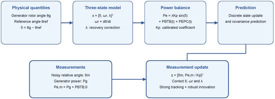
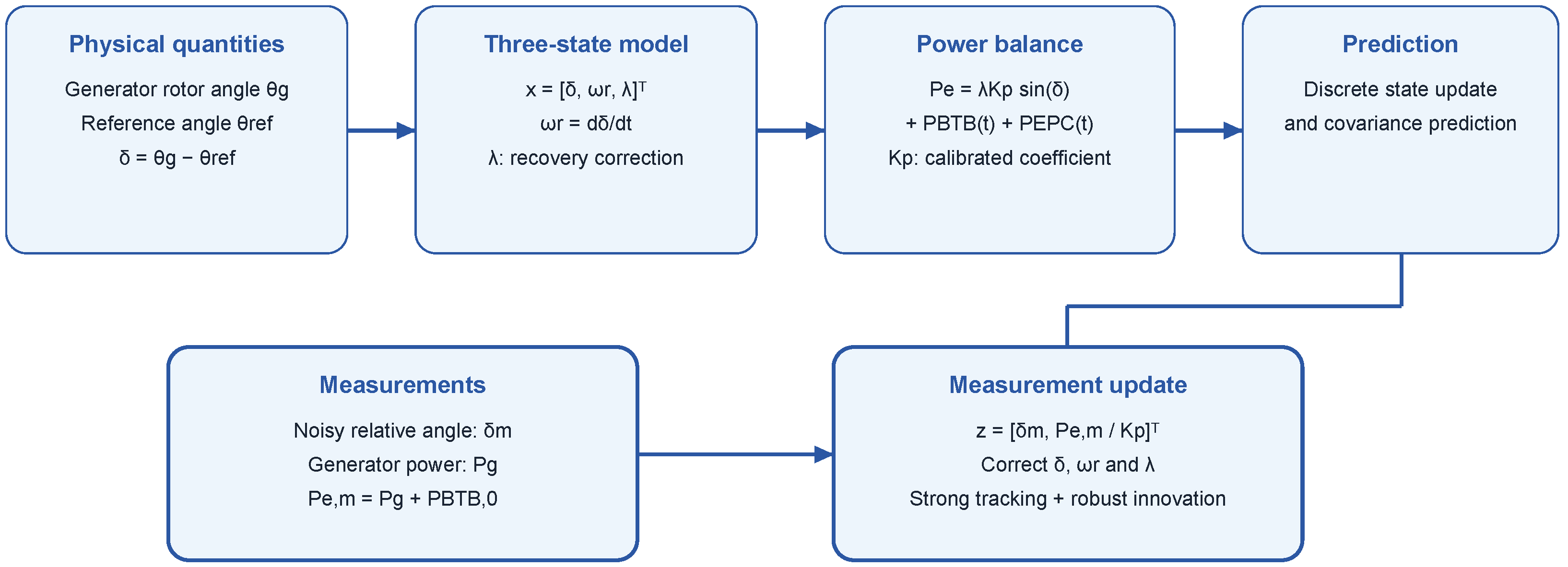
The model uses the relative-rotor-angle measurement to provide direct state information and the active-power measurement to constrain the recovery of . The resulting power-corrected three-state observer structure is summarized in Figure 1.
3. Power-Corrected Strong-Tracking Filtering Method
3.1. Basic EKF Recursion
The state and measurement equations are estimated online using an extended Kalman filter (EKF). The discrete nonlinear system is
where and are process and measurement noise. The prediction and update equations follow the standard EKF form:
The Joseph covariance form is used to preserve covariance symmetry during the update.
3.2. Three-State Prediction and Linearization
With sampling time , the discrete prediction model is
The prediction uses and as controller-side available signals. In the PSCAD closed-loop cases, the EPC term is taken from the active-power reference issued by the BTB controller and is synchronized with the observer sampling instant. If the measured converter active power is available in an engineering implementation, it can replace the command value in the same prediction equation. Any short converter response delay within one sampling interval is treated as part of the reduced-order model mismatch and is further compensated by the strong-tracking factor and the correction state. These equations use a forward-Euler step: the next angle equals the previous angle plus times relative angular speed, while the next relative angular speed equals the previous speed plus times relative angular acceleration. Thus, an angle is not equated to a speed, and a speed is not equated to its acceleration. Superscripts + and − denote posterior and predicted estimates, respectively; k is the sample index. The input comprises the available BTB and EPC power signals. To simplify the representation of the Jacobian matrix, the intermediate variable is defined. The corresponding state-transition Jacobian is with respect to , evaluated at :
Here, is the sampling interval, the synchronous angular speed, the equivalent inertia, the equivalent damping, the equivalent mechanical input, and the calibrated power-angle coefficient. All state quantities in this transition Jacobian are evaluated at the previous posterior estimate.
3.3. Power-Constrained Measurement Update
For the two-channel measurement function in (16), the measurement Jacobian is taken with respect to and evaluated at the predicted state :
After each filtering update, the correction coefficient is limited:
3.4. Strong-Tracking Factor
The filter improves responsiveness to abrupt fault disturbances and model mismatch through the normalized innovation statistic
where m is the measurement dimension and is the innovation. The fading factor is constructed as
The predicted covariance is modified by
When , the filter is equivalent to a standard EKF. Values above unity enlarge the predicted covariance and strengthen the response to current measurements when the innovation increases.
3.5. Huber Innovation Saturation
To suppress the influence of abnormal measurement points under strong noise, a Huber-type innovation saturation is applied to each channel:
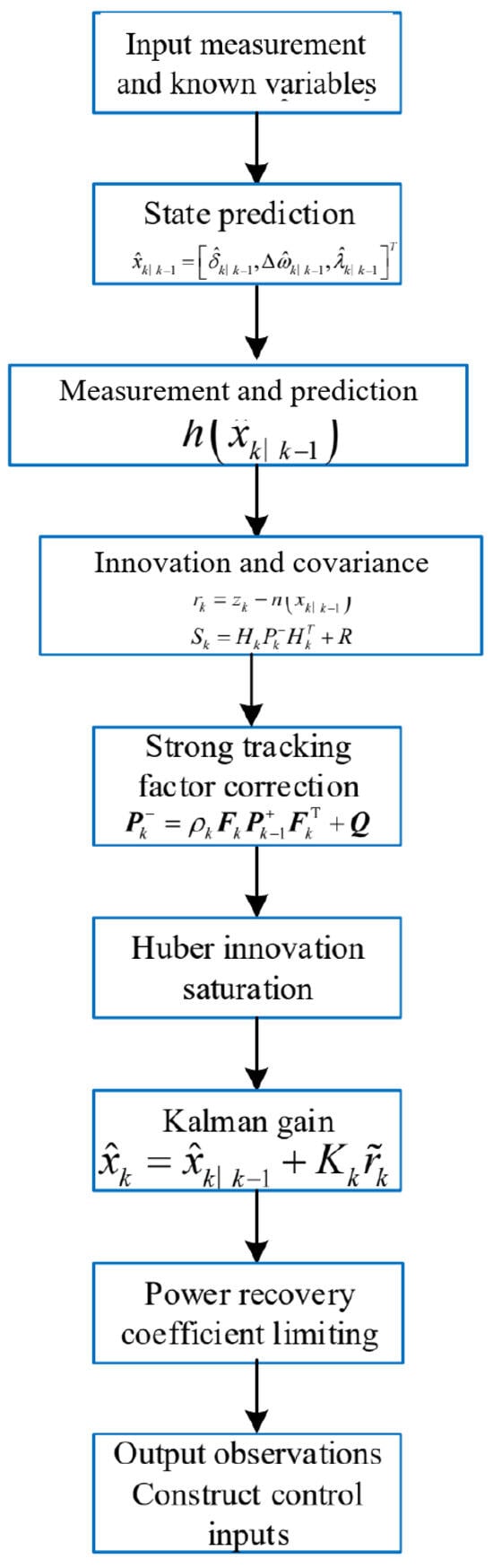
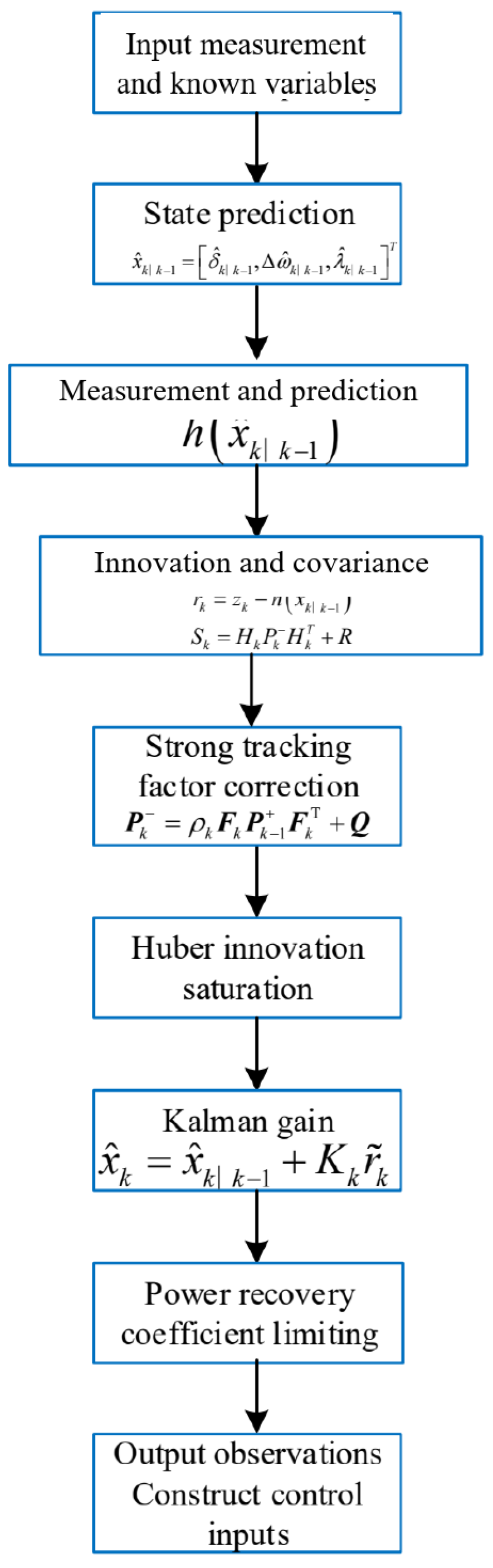
where is the standard deviation associated with the innovation covariance and c is the Huber saturation coefficient. The strong-tracking factor improves the tracking speed under model mismatch, whereas Huber saturation suppresses measurement outliers. For control output, the derivative of measured angle is smoothed in a short window, and a minimum holding time is imposed to reduce decision chattering. Figure 2 shows the complete power-corrected strong-tracking filtering procedure.
Figure 2.
Power-corrected strong-tracking filtering algorithm.
4. Case Studies
4.1. System and Parameter Settings
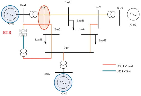
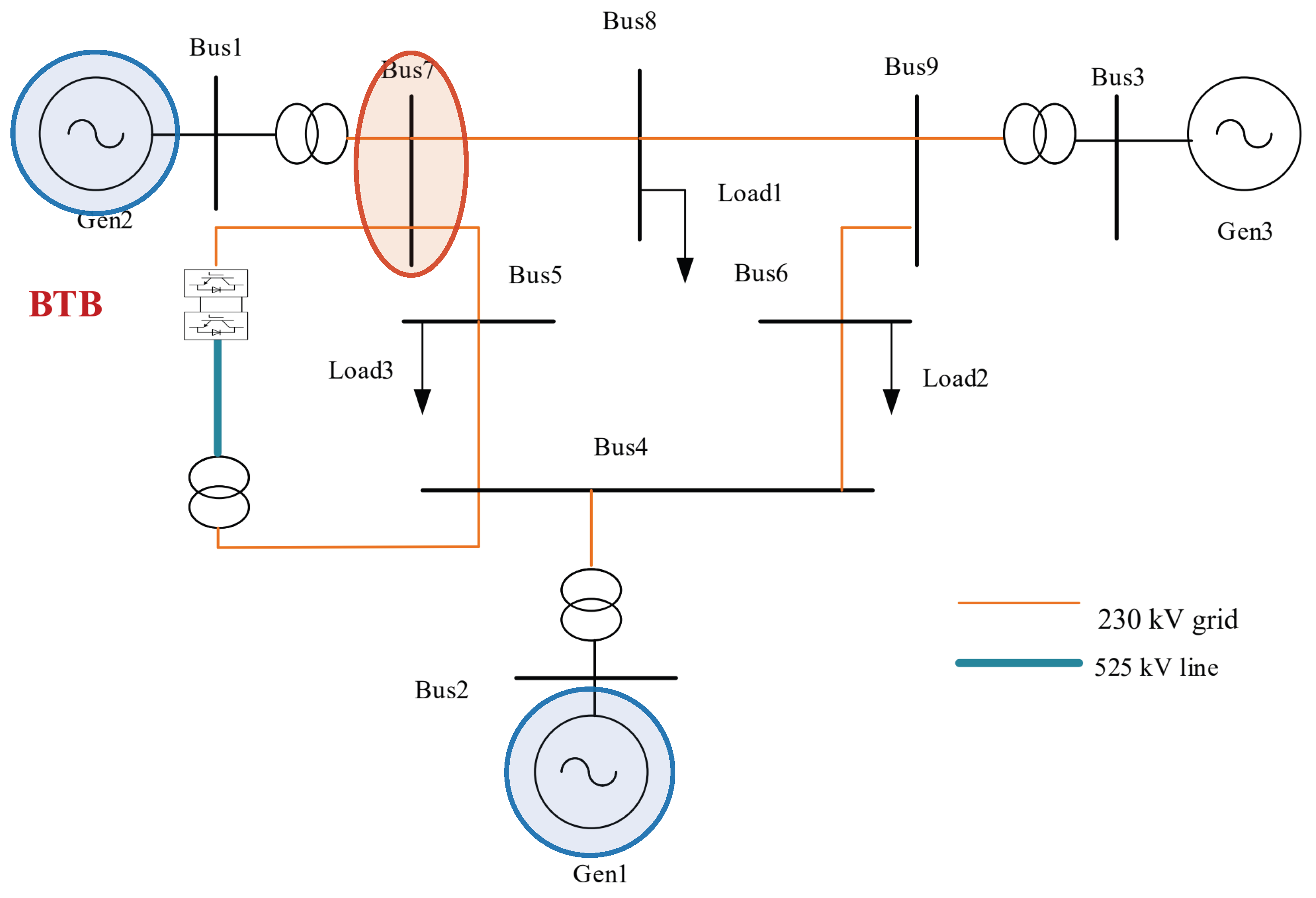
The proposed observer was evaluated on an equivalent three-machine system with a BTB converter station built in PSCAD/EMTDC. The tested cases shared that system model and operating point; the fault duration, measurement-noise level, and random seed varied as specified below. The system topology is shown in Figure 3. The listed pre-fault generator outputs totaled 786 MW, while the three nominal load active powers totaled 830 MW; the BTB station was rated at 500 MVA, and its pre-fault active-power transfer was 100 MW (20% of its apparent-power rating). These nominal quantities describe the tested operating point and component size, but they do not by themselves establish an AC transfer-capacity limit or a static stability margin, which would require a separate steady-state loadability assessment. The benchmark followed the classical three-machine nine-bus structure. A high-voltage tie channel was added between bus 4 and bus 7, and a 500-MVA BTB voltage-source-converter station was connected through transformers to represent flexible interconnection in a synchronous AC system. EPC was implemented by modulating the active-power reference of the BTB station on the bus-4–bus-7 tie channel. Generator 1 was used as the reference unit, and the rotor angle of generator 2 relative to generator 1 was observed. The relative-rotor-angle truth was obtained from the PSCAD output, and reproducible random noise was superimposed to construct noisy synchronized measurements. A three-phase short-circuit fault was applied at bus 7. In the typical case, the fault started at PSCAD time 8.00 s and was cleared at 8.10 s. The full-period plots use time measured from the 6.00 s analysis start, so the same events appear at 2.00 and 2.10 s; the transient-window error plot resets time to zero at fault inception. Additional 0.08 s and 0.12 s fault-duration cases were used to examine sensitivity to the fault-clearing time. Circuit-breaker line isolation, automatic reclosing, and local generator automation actions are not represented in these cases. The main system parameters and observer-control parameters are listed in Table 1 and Table 2, respectively. For the offline comparisons, MW was the mean of over the pre-fault PSCAD interval 6.00–7.80 s; the embedded closed-loop cases used their separate pre-fault calibration of 813.92 MW. The short-circuit ratio, PLL parameters, and BTB parameters are simulation settings selected to represent a weak-grid BTB transient-control scenario rather than measured values from a specific project.
Figure 3.
Equivalent three-machine nine-bus topology. Blue ellipses identify the reference generator (Gen1) and observed generator (Gen2); the red ellipse identifies the three-phase short-circuit location at Bus7.
Table 1.
Main parameters of the equivalent three-machine system.
Table 2.
Main observer and control parameters.
In closed-loop validation, EPC aims to reduce the first-swing peak of the generator relative rotor angle. EPC is triggered by voltage sag and exits according to rotor-angle recovery: when the fault-point voltage is lower than 0.7 pu, active-power support is activated; after EPC insertion, the transient recovery degree is judged from the rate of the input angle signal, and EPC exits when the derivative stays below the threshold for a minimum holding time. The observer and controller in the PSCAD simulation were updated every ms; this is the simulation update interval, not an assumed PMU reporting rate. Communication delay was not explicitly modeled in this study. The covariance and saturation parameters in Table 2 are internal observer tuning parameters selected from prior measurement statistics and repeated time-domain trials. The two-degree and five-degree noise levels reported in the case studies denote the standard deviations of synthetic noise injected into the raw relative-rotor-angle channel; they are not the same as the nominal covariance entries used inside the filter.
4.2. Offline Observation Performance
4.2.1. Comparison of Filtering Methods
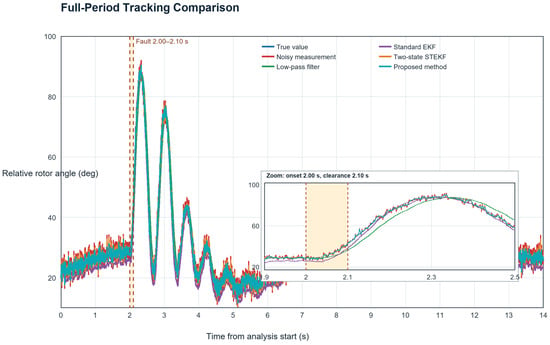
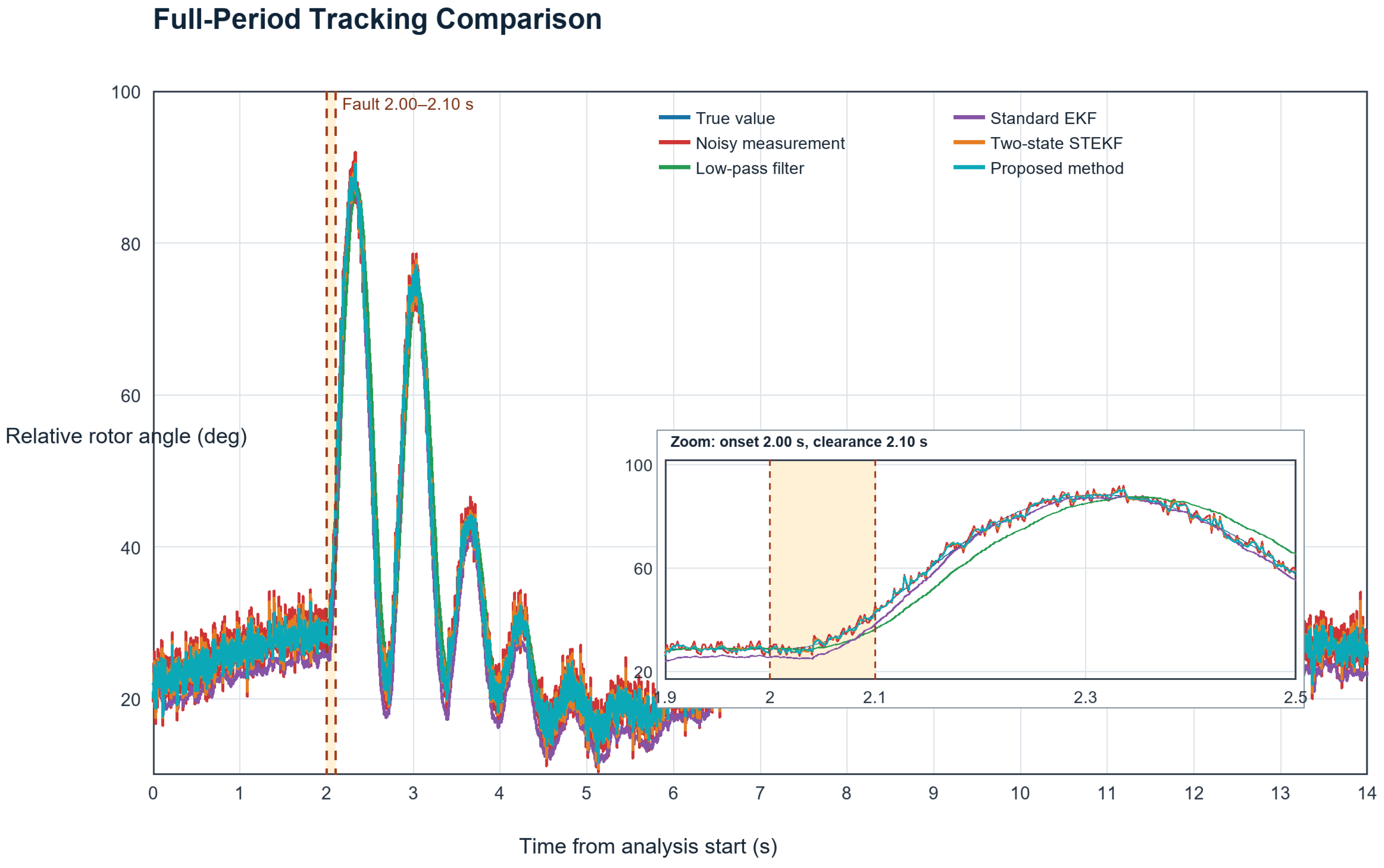
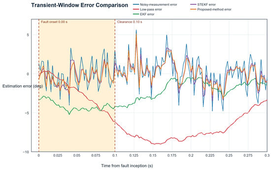
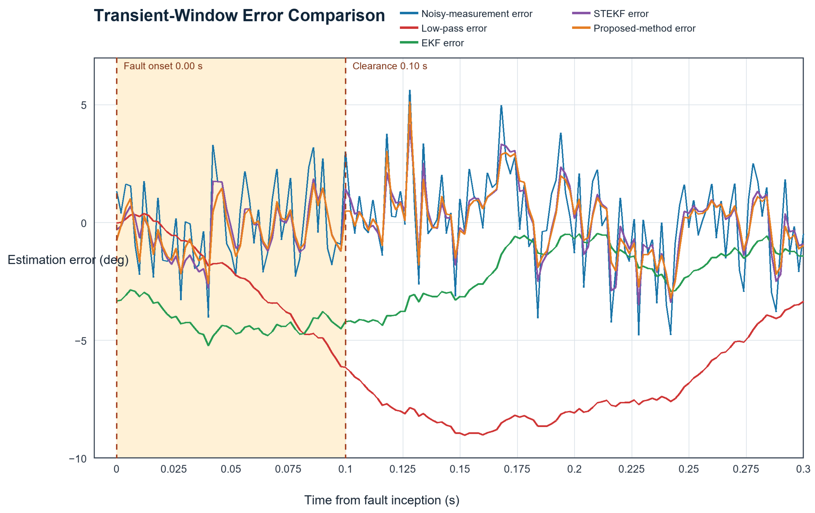
For the typical 0.10 s fault-duration case, five methods were compared. The root-mean-square error (RMSE) was used to quantify full-period and fault-window estimation accuracy. The fault window was defined as the interval from fault inception to the end of the first-swing recovery stage used for the EPC exit assessment; for the 0.10 s case, this corresponded to 2.00–2.30 s on the full-period plot (8.00–8.30 s in PSCAD time, or 0–0.30 s after fault inception in the transient-window plot). The fault was cleared at 2.10 s on the full-period plot, equivalent to 0.10 s in the transient-window plot. Table 3 summarizes the estimation errors, and Figure 4 and Figure 5 show the corresponding full-period tracking and transient-window error curves. Low-pass filtering reduces the full-period RMSE from 2.008 degrees for the noisy measurement to 1.861 degrees, but the fault-window RMSE increases to 6.265 degrees, indicating non-negligible phase lag during fast transient variation. The standard EKF is affected by reduced-order model mismatch; both its full-period and fault-window errors are larger than those of the noisy measurement. This behavior indicates that an uncorrected low-order model can degrade fault-period estimation. The two-state strong-tracking extended Kalman filter (STEKF) alleviates model mismatch through the strong-tracking factor, but its full-period noise suppression remains limited. After the power-recovery correction coefficient and active-power measurement constraint are introduced, the proposed observer attains the lowest errors among the compared methods.
Table 3.
Comparison of different filtering methods.
Figure 4.
Full-period tracking comparison under 2-degree noise and 0.10 s fault duration. The overlapping trajectories show the overall swing, while Table 3 and the fault-window error plot in Figure 5 quantify differences that are difficult to discern at full scale. Time is measured from the 6.00 s PSCAD analysis start; dashed lines mark fault inception at 2.00 s and clearance at 2.10 s. The inset enlarges the fault interval.
Figure 5.
Transient-window error comparison under 2-degree noise and 0.10 s fault duration. Time is measured from fault inception; dashed lines mark fault onset at 0 s and clearance at 0.10 s. The shaded interval is the short-circuit period.
4.2.2. Ablation Study
To analyze the contribution of each module, an ablation study was performed under two-degree noise. The two-state STEKF served as the baseline, and the power-recovery correction coefficient and active-power measurement constraint were introduced successively. As shown in Table 4, introducing the correction state reduces the fault-window RMSE from 1.373 degrees to 1.325 degrees, confirming that the correction coefficient improves transient tracking under post-fault power-recovery lag and model mismatch. Adding the active-power measurement constraint further reduces the full-period RMSE to 1.222 degrees and the fault-window RMSE to 1.281 degrees, improving overall estimation accuracy.
Table 4.
Ablation-study results.
4.2.3. Adaptability to Transient-Fault Severity
Table 5 reports the observation results under different fault durations. Without EPC, the first-swing peaks are about 74.32, 88.70, and 108.36 degrees for the three cases, respectively; longer fault duration creates stronger transient impact. Under these different transient severities, the fault-window RMSEs of the proposed method remain 1.242, 1.226, and 1.298 degrees, indicating that estimation accuracy remains stable as fault duration increases.
Table 5.
Adaptability under different transient-fault intensities.
4.3. Closed-Loop Validation as Real-Time Control Input
4.3.1. Closed-Loop Comparison Under Different Observation Inputs
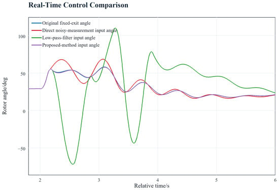
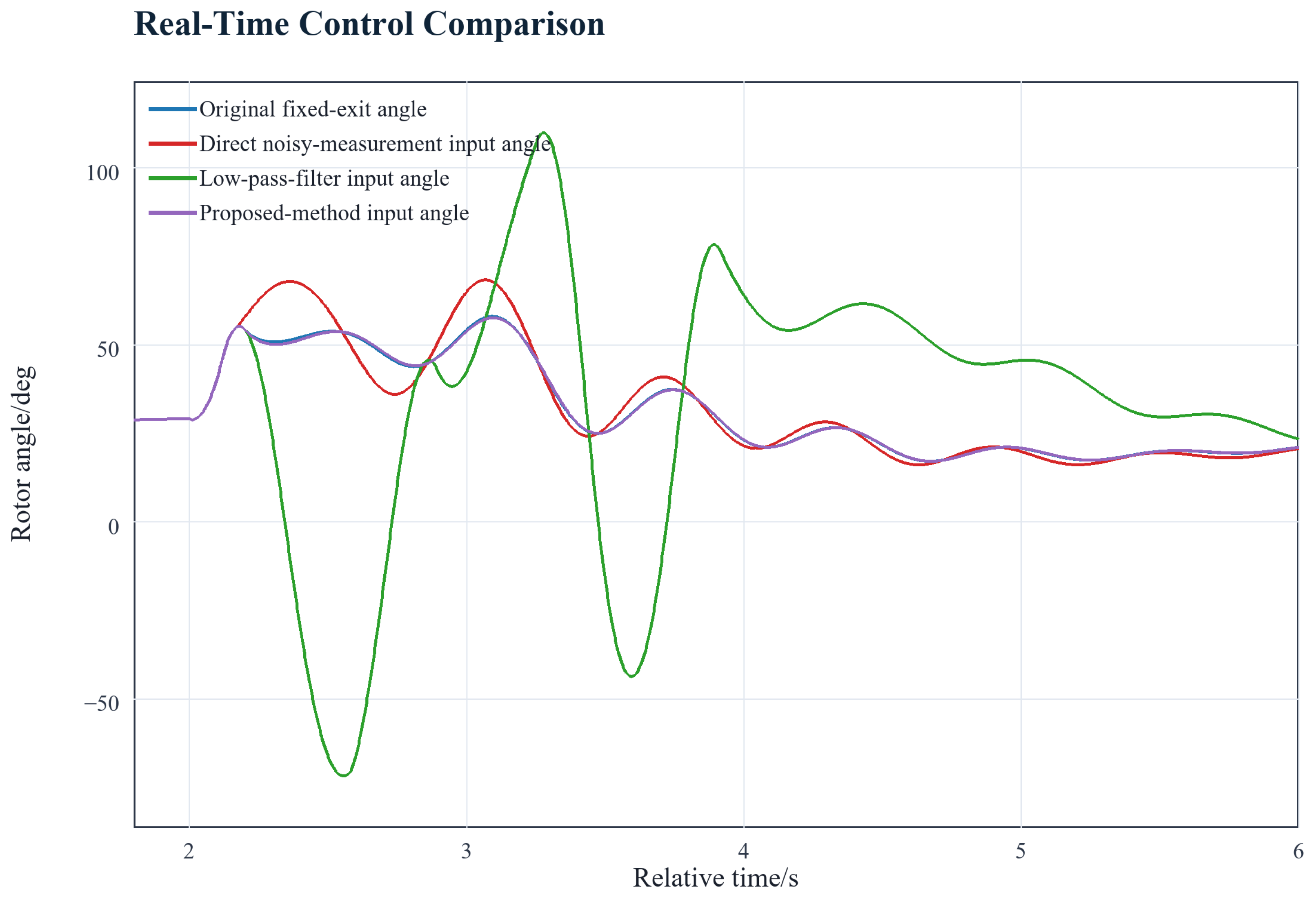
Table 6 compares closed-loop response indices for three input signals, and Figure 6 shows the corresponding real-time control trajectories. In this study, an appropriate exit instant means that the EPC action is retained until the input-angle derivative satisfies the recovery threshold for the required holding time, while avoiding prolonged support that may aggravate the following swing. Direct noisy input causes EPC to exit at 2.164 s, earlier than this recovery condition, and the post-exit rotor-angle peak rebounds to 68.29 degrees. This result indicates that noise can falsely trigger the exit criterion. Low-pass-filter input causes delayed exit: EPC exits at 2.574 s, and the maximum angle reaches 109.88 degrees because filtering lag delays the recovery signal. With the proposed observer, EPC exits at 2.200 s and the maximum angle is limited to 57.58 degrees, showing improved closed-loop performance relative to the two direct processing methods. The value is not claimed as a global optimum; rather, it demonstrates that the observer output is more compatible with the specified EPC exit logic than the two direct input signals.
Table 6.
Comparison of real-time control results.
Figure 6.
Closed-loop EPC comparison under 2-degree noise and 0.10 s fault duration.
4.3.2. Typical Closed-Loop Case Under Strong Noise
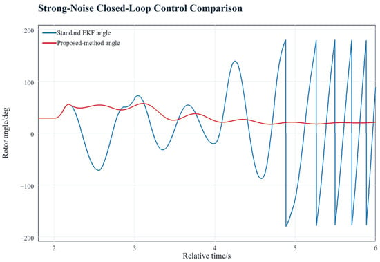
To further evaluate the influence of observation input under strong noise, a typical case with five-degree angle-measurement noise was selected, with random seed 20260518. Although the steady-state phase-angle error of a modern PMU is normally much smaller, severe transient disturbances may degrade angle extraction because of frequency deviation, harmonics, and decaying DC components. The five-degree case was therefore used as an extreme stress test of the observer’s robustness boundary rather than as a normal operating measurement condition. Figure 7 compares the closed-loop responses of the standard EKF input and the proposed input. Under strong noise, the standard EKF output is affected jointly by measurement fluctuation and model mismatch, which delays EPC exit and causes the subsequent rotor angle to increase rapidly toward the instability boundary. The proposed observer enhances transient-observation robustness through strong-tracking adjustment, power-measurement constraint, and innovation saturation, keeping the exit instant within the intended recovery interval and suppressing the subsequent rotor-angle swing.
Figure 7.
Closed-loop EPC comparison under 5-degree strong noise.
4.3.3. Multi-Seed Statistics Under Strong Noise
To evaluate statistical robustness under strong noise, ten random seeds from 20260518 to 20260527 were tested with five-degree angle-measurement noise. EPC duration longer than 0.35 s was defined as a delayed exit. This threshold was chosen as an engineering limit beyond the minimum holding time; in the tested control logic, it identified cases in which EPC remained active well beyond the first-swing recovery indication and may interfere with the following swing. As shown in Table 7, standard EKF input produces angle instability in six of 10 cases, maximum angle above 90 degrees in six of 10 cases, and delayed EPC exit in six of 10 cases. The average maximum angle is 132.31 degrees, and the standard deviation of EPC end time is 0.303 s. With the proposed input, instability is reduced to one of 10 cases, maximum angle above 90 degrees to three of 10 cases, and delayed exit to two of 10 cases. The average maximum angle decreases to 81.79 degrees, and the standard deviation of EPC end time decreases to 0.145 s. The proposed method does not eliminate all instabilities under arbitrary noise sequences; seed 20260521 still becomes unstable, suggesting that protection blocking, abnormal-innovation detection, or stricter control-security constraints are needed under extreme noise.
Table 7.
Statistical results under strong noise with multiple random seeds.
5. Conclusions
This study assessed a power-corrected strong-tracking observer using offline estimation and embedded closed-loop control in the tested three-machine nine-bus BTB system. The quantitative findings are specific to the stated PSCAD model, operating point, fault cases, and synthetic measurement-noise levels; they should not be generalized to untested network topologies or protection sequences.
Under two-degree angle-measurement noise, the proposed observer achieved a full-period RMSE of 1.222 degrees, compared with 3.457 degrees for the standard EKF and 1.503 degrees for the two-state STEKF. These correspond to RMSE reductions of 64.7% and 18.7%, respectively. Its fault-window RMSE was 1.281 degrees, 6.7% below the two-state STEKF value of 1.373 degrees. The low-pass filter yielded a lower full-period RMSE than the noisy measurement, but its 6.265-degree fault-window RMSE showed the cost of delayed transient tracking in that case.
The ablation results separated the contributions of the two power-related changes. Adding the correction state to the two-state STEKF reduced fault-window RMSE from 1.373 to 1.325 degrees (3.5%). Adding the active-power measurement constraint then reduced full-period RMSE from 1.498 to 1.222 degrees (18.4%) and fault-window RMSE from 1.325 to 1.281 degrees (3.3%). These values indicate complementary, case-dependent effects rather than a uniform gain under every metric.
In the two-degree closed-loop comparison, the proposed input produced an EPC exit at 2.200 s and a maximum relative angle of 57.58 degrees, compared with 68.29 degrees for direct noisy input and 109.88 degrees for low-pass-filter input. In ten five-degree strong-noise runs, the counts of instability and delayed exit changed from 6/10 and 6/10 with standard EKF input to 1/10 and 2/10 with the proposed input. These counts describe the tested random seeds and should not be interpreted as general failure probabilities. Future work will examine additional fault locations, power-transfer levels, communication delays, line isolation and automatic reclosing, and the influence of local generator automation, including high-action excitation regulators, on EPC under substantial measurement noise.
Author Contributions
Conceptualization, C.Y. and H.Z.; methodology, C.Y. and T.L.; software, T.L. and Z.Y.; validation, T.L. and B.Y.; formal analysis, T.L. and D.S.; investigation, H.Z. and D.S.; resources, H.Z.; data curation, D.S., T.L. and Z.Y.; writing—original draft preparation, T.L.; writing—review and editing, Y.Z. and T.L.; visualization, Z.Y.; supervision, Y.Z.; project administration, D.S. and H.Z. All authors have read and agreed to the published version of the manuscript.
Funding
This research was funded by the Science and Technology Project of State Grid Shandong Electric Power Company, grant number 520625250001.
Institutional Review Board Statement
Not applicable.
Informed Consent Statement
Not applicable.
Data Availability Statement
The simulation data supporting the findings of this study are available from the corresponding author upon reasonable request.
Conflicts of Interest
Canran Yang, Hongli Zheng, Donglei Sun, Bin Yang, and Zhenhua Yuan were employed by the Economic and Technology Research Institute, State Grid Shandong Electric Power Company. This study received funding from Shandong Electric Power Company. Through its employed co-authors, the company contributed to the conception and design of the study and provided engineering data, system parameters, and simulation models used in the research. The authors from both institutions jointly conducted the study and interpreted the results. The original manuscript was drafted by Tong Liu and revised by Yongzhi Zhou and Tong Liu, as recorded in the Author Contributions section; all authors approved its submission. The remaining authors declare no other commercial or financial relationships that could be construed as a potential conflict of interest.
References
- Li, X.; Zeng, Q.; Wang, Y.; Zhang, Y. Control strategies of voltage source converter based direct current transmission system. High Volt. Eng. 2016, 42, 3025–3037. [Google Scholar]
- Latorre, H.F.; Ghandhari, M.; Soder, L. Active and reactive power control of a VSC-HVDC. Electr. Power Syst. Res. 2008, 78, 1756–1763. [Google Scholar] [CrossRef] [Scilit]
- Rao, H.; Zhou, Y.; Li, W.; Zou, C.; Wang, Z. Engineering application and development prospect of VSC-HVDC transmission technology. Autom. Electr. Power Syst. 2023, 47, 1–11. [Google Scholar] [CrossRef] [Scilit]
- Yuan, Z.; Guo, P.; Liu, G.; Zhao, Y.; Wei, X. Review on control and protection for renewable energy integration through VSC-HVDC. High Volt. Eng. 2020, 46, 1473–1488. [Google Scholar]
- Li, J.; Xia, Y.; Yao, W.; Yang, R.; Wen, J. Additional frequency coordinated control for Chongqing-Hubei back-to-back VSC-HVDC and Longquan-Zhengping LCC-HVDC. South. Power Syst. Technol. 2023, 17, 134–144. [Google Scholar]
- Preece, R.; Milanovic, J.V.; Almutairi, A.M.; Marjanovic, O. Damping of inter-area oscillations in mixed AC/DC networks using WAMS based supplementary controller. IEEE Trans. Power Syst. 2013, 28, 1160–1169. [Google Scholar] [CrossRef] [Scilit]
- Li, D.; Li, J.; Zhou, Y.; Wen, J. Reactive power-coordinated control of a synchronous condenser and VSC-HVDC in the sending-side near region power grid of an LCC-HVDC. Electr. Power Constr. 2023, 44, 148–160. [Google Scholar]
- Li, H.; Li, Y.; Meng, Y.; Yan, K. Coordinated frequency support strategy for VSC-HVDC integrated offshore wind farm system. Front. Energy Res. 2024, 12, 1351353. [Google Scholar] [CrossRef] [Scilit]
- Zhang, Z.; Gao, B.; Suo, Z.; Yao, L. Adaptive dual droop control strategy of VSC-HVDC for supporting frequency stability of sending-end system with renewable energy. Electr. Power Constr. 2025, 46, 1–11. [Google Scholar]
- Zhang, X.; Hao, Z.; Li, J.; Yang, S.; Li, Y. Transient DC-link voltage oscillation stability assessment of VSC-HVDC systems using Lyapunov direct method. Int. J. Electr. Power Energy Syst. 2024, 157, 109873. [Google Scholar] [CrossRef] [Scilit]
- Cai, D.; Zhao, S.; Li, G.; Wang, Z. Transient synchronous stability analysis of hydropower and photovoltaic integration system via VSC-HVDC considering current limiting. South. Power Syst. Technol. 2026, 20, 1–10. [Google Scholar]
- Luo, Y.; Yao, J.; Chen, Z.; Wen, J.; Jiang, Q. Transient synchronous stability analysis and enhancement control strategy of a PLL-based VSC system during asymmetric grid faults. Prot. Control Mod. Power Syst. 2023, 8, 35. [Google Scholar] [CrossRef] [Scilit]
- Liu, Y.; Singh, A.K.; Zhao, J.; Meliopoulos, A.P.; Pal, B.; Ariff, M.A.M.; Van Cutsem, T.; Glavic, M.; Huang, Z.; Kamwa, I.; et al. Dynamic state estimation for power system control and protection. IEEE Trans. Power Syst. 2021, 36, 5909–5921. [Google Scholar] [CrossRef] [Scilit]
- Zhou, N.; Meng, D.; Huang, Z.; Welch, G. Dynamic state estimation of a synchronous machine using PMU data: A comparative study. IEEE Trans. Smart Grid 2015, 6, 450–460. [Google Scholar] [CrossRef] [Scilit]
- Chen, L.; Bi, T.; Li, J.; Xue, A.; Li, Q.; Yang, Q. Dynamic state estimator for synchronous machines based on cubature Kalman filter. Proc. CSEE 2014, 34, 2706–2713. [Google Scholar]
- Ghahremani, E.; Kamwa, I. Online state estimation of a synchronous generator using unscented Kalman filter from phasor measurement units. IEEE Trans. Energy Convers. 2011, 26, 1099–1108. [Google Scholar] [CrossRef] [Scilit]
- Basetti, V.; Chandel, A.K.; Shiva, C.K. Square-root cubature Kalman filter based power system dynamic state estimation. Sustain. Energy Grids Netw. 2022, 31, 100712. [Google Scholar] [CrossRef] [Scilit]
- An, J.; Yang, Z.; Zhou, Y.; Gui, J.; Shi, Y. Dynamic state estimator for synchronous machines based on square root cubature Kalman filter. Trans. China Electrotech. Soc. 2017, 32, 234–240. [Google Scholar]
- Wu, C.; Zheng, K.; Xu, X.; Lu, J. Dynamic state estimation of power system based on adaptive interpolation strong tracking extended Kalman filter. Power Syst. Technol. 2023, 47, 2078–2091. [Google Scholar]
- Chen, T.; Liu, F.; Luo, H.; Foo, E.Y.S.; Sun, L.; Sun, Y.; Gooi, H.B. A new robust dynamic state estimation approach for power systems with non-Gaussian noise. Int. J. Electr. Power Energy Syst. 2024, 158, 109948. [Google Scholar] [CrossRef] [Scilit]
- Sun, G.; Huang, M.; Wen, J.; Cheng, S.; Yuan, J. Dynamic state estimation for synchronous machines based on unscented transformation of strong tracking filter. Proc. CSEE 2016, 36, 615–623. [Google Scholar]
- Lin, J.; Hong, H.; Song, W.; Jiang, C.; Lu, C. Power system adaptive robust dynamic state estimation based on hybrid measurements. Trans. China Electrotech. Soc. 2025, 40, 4694–4707. [Google Scholar]
- Zhao, J.; Mili, L. Robust unscented Kalman filter for power system dynamic state estimation with unknown noise statistics. IEEE Trans. Smart Grid 2019, 10, 1215–1224. [Google Scholar] [CrossRef] [Scilit]
- Zhu, M.; Liu, H.; Bi, T. Robust dynamic state estimation of doubly-fed induction generator considering measurement correlation in wind farms. Trans. China Electrotech. Soc. 2023, 38, 726–740. [Google Scholar]
- Jamalinia, E.; Khazaei, J.; Blum, R.S. Data-driven dynamic state estimation in power systems via sparse regression unscented Kalman filter. Sustain. Energy Grids Netw. 2024, 40, 101571. [Google Scholar] [CrossRef] [Scilit]

Disclaimer/Publisher’s Note: The statements, opinions and data contained in all publications are solely those of the individual author(s) and contributor(s) and not of MDPI and/or the editor(s). MDPI and/or the editor(s) disclaim responsibility for any injury to people or property resulting from any ideas, methods, instructions or products referred to in the content. |
© 2026 by the authors. Licensee MDPI, Basel, Switzerland. This article is an open access article distributed under the terms and conditions of the Creative Commons Attribution (CC BY) license.