


Abstract
Sidetracking is a critical operation for bypassing damaged well sections and accessing bypassed hydrocarbons in mature reservoirs, but conventional small-diameter casing and cementing technologies face severe limitations due to narrow-clearance hydraulics, mechanical drag, and aggressive corrosive downhole environments. To overcome these challenges, this paper proposes a paradigm-shifting biomimetic approach: the in-situ additive manufacturing of a wellbore liner directly behind the drill bit during sidetracking. Inspired by the apical growth of climbing plants, a conceptual bottomhole assembly (BHA) was designed to extrude a continuous carbon-fiber-reinforced polyetheretherketone (CCF/PEEK) composite shell. A coupled multiphysics framework was established to evaluate the technology’s feasibility under representative downhole conditions. Hydrodynamic modeling of the non-Newtonian polymer melt demonstrates that shear-thinning rheology minimizes extrusion pressure requirements, necessitating only a 3.5% pressure increase (46.76 MPa/6782 psi) when doubling the rate of penetration from 5 to 10 m/h. Thermal and crystallization kinetics simulations using the Nakamura framework show that the liner core achieves an optimal crystallinity of 32% within 45 s post-extrusion, ensuring monolithic interlaminar cohesion. Geomechanical analysis using the Tsai–Wong tensor failure criterion confirms that an 8.5 mm thick CCF/PEEK liner provides a collapse resistance of 61.2 MPa/8876 psi, comparable to conventional API K55 steel casings but with a 68.8% reduction in weight and absolute corrosion immunity. Finally, we define the critical operational limitations of the technology, establishing a bottomhole temperature limit of 180 °C/356 °F and a maximum borehole cavern factor of 1.35.
1. Introduction
The recovery of bypass hydrocarbons from mature reservoirs represents a critical vector in modern petroleum engineering. Sidetracking from existing wellbores is widely recognized as one of the most cost-effective methods to access bypassed oil and gas zones, bypass damaged well sections, or target localized sweet spots [1]. However, drilling and completing small-diameter sidetracks presents severe technical challenges that push conventional casing and cementing technologies to their physical and economic limits.
In standard sidetracking operations, completing the newly drilled lateral section requires running a small-clearance steel liner and subsequent cementing. The extremely narrow micro-annulus between the outer casing wall and the formation frequently leads to poor cement placement, resulting in incomplete zonal isolation and early water or gas breakthrough [2]. Furthermore, deploying thin-walled steel liners in highly tortuous or extended-reach sidetracks involves high drag forces, leading to risks of stuck pipe or mechanical failure [1]. In aggressive downhole environments containing elevated levels of hydrogen sulfide (H2S) and carbon dioxide (CO2), standard carbon steel casings suffer from rapid corrosion, drastically shortening the production life of the well [3].
To address these limitations, several alternative methodologies have been explored, including expandable casing systems and pre-perforated composite liners [4]. While these technologies mitigate some operational risks, they do not eliminate the necessity of heavy logistics, pipe manufacture, and subsequent surface-to-borehole deployment operations.
A paradigm shift is offered by the emerging field of bioinspired robotics and additive manufacturing. In nature, climbing plants (such as ivy or vines) navigate complex, unstructured spaces by utilizing apical growth, wherein new structural tissue is added sequentially at the growing tip. This concept was successfully translated into engineering by Del Dottore et al. through the development of the FiloBot—a robot that builds its own structural body via continuous polymer extrusion to move through 3D space [5]. Applying this biomimetic principle to the drilling environment offers a unique opportunity: instead of deploying a pre-fabricated steel pipe from the surface, the BHA can manufacture its own continuous, high-strength composite liner in-situ directly behind the drill bit.
This paper proposes and mathematically validates a novel system for the in-situ additive manufacturing of wellbore liners using a CCF/PEEK composite during the drilling process. The primary objective is to evaluate the feasibility of this technology under real downhole conditions.
2. Materials and Methods
2.1. Principle of Operation
The operational framework of the proposed biomimetic drilling system is inspired by the continuous additive manufacturing and adaptive growth mechanisms observed in Filobot [5]. In traditional sidetracking, mechanical drilling and wellbore lining (casing/liner deployment) are sequential, discrete operations, which inherently maximizes the exposure time of unstable formations to drilling fluids. The developed concept reengineers this workflow by combining rock destruction, directional navigation, and in-situ structural lining into a single, synchronized, continuous process.
The downhole cycle of the self-growing BHA is governed by three interconnected functional stages, executing simultaneously in real-time:
Rock Disruption and Advance: The specialized bit or mill at the front of the BHA performs the initial window cutting in the production casing and initiates the sidetrack trajectory [6]. Unlike conventional rotary systems where torque is transmitted from the surface, the drilling torque here is generated locally by a downhole mud motor or an electric drive integrated into the BHA, minimizing mechanical stress on the drill string.
In-Situ Composite Extrusion: Positioned directly behind the directional/telemetry module (MWD/LWD), a specialized multi-nozzle extrusion head continuously deposits a high-performance thermoplastic polymer (such as CCF/PEEK) onto the freshly exposed rock face [7]. The extrusion head rotates independently or in synchronization with the BHA geometry to lay down overlapping, continuous helical layers of the polymer material.
Anchoring and Interlocking: As the extruded material cools and solidifies under downhole conditions, it forms a rigid, high-strength structural shell (liner). Crucially, the BHA utilizes expanding anchoring pads or a specialized crawler-like propulsion system that grips the already cured polymer liner. By pushing against this newly created synthetic wellbore wall, the system generates the necessary weight-on-bit (WOB) locally, eliminating the risk of buckling in the upper sections of the drill string.
To ensure precise wellbore architecture and avoid geometric conflicts, the rate of BHA penetration (ROP) must be dynamically coupled with the polymer extrusion parameters. The fundamental volumetric balance governing the operation is expressed as follows:
where:
- Qext is the volumetric extrusion rate of the polymer melted (m3/s);Rwb is the actual radius of the drilled wellbore (m);Rin is the internal radius of the newly printed polymer liner (m).
By continuously regulating Qext and the rotational speed of the extrusion matrix based on real-time LWD caliper data, the system automatically adapts to washouts and changes in wellbore diameter. Furthermore, by deliberately applying differential extrusion rates across the circumference (depositing a thicker layer on one side), the system mimics the phototropic bending of Filobot, allowing for smooth, highly controlled trajectory corrections without the mechanical complexity of traditional rotary steerable systems (RSS). Maintaining long-term wellbore integrity and mitigating borehole collapse under severe asymmetric tectonic stress regimes remain pivotal challenges across complex directional drilling and sidetracking operations [8]. In mechanically sensitive and low-competence formations, severe localized stress concentration frequently triggers catastrophic shear sloughing, borehole enlargement, and progressive casing collapse if mud hydrostatic pressure and supporting liner stiffness are unoptimized [9,10]. Addressing these structural vulnerabilities demands not only rigorous mud density control but also the immediate downhole deployment of high-strength structural barriers capable of arresting hole ovalization and preventing plastic rock failure [8,9,10]. This continuous isolation of the formation immediately upon exposure provides an absolute barrier against fluid invasion, completely eliminating wellbore collapse and circulation losses during sidetrack placement.
2.2. Downhole 3D-Printer Component Design
To successfully translate the biomimetic principles of Filobot into sidetracking operations, the BHA must integrate a ruggedized, downhole-scale additive manufacturing unit [5]. Unlike the laboratory-scale Filobot prototype, which utilizes a compact 40-mm fixed-diameter extrusion head for ambient-pressure operations, the downhole 3D-printer component must withstand extreme differential pressures (up to 9000 psi/62.1 MPa), high ambient temperatures (up to 390 °F/199 °C), and geometric irregularities of the borehole wall [2,6].
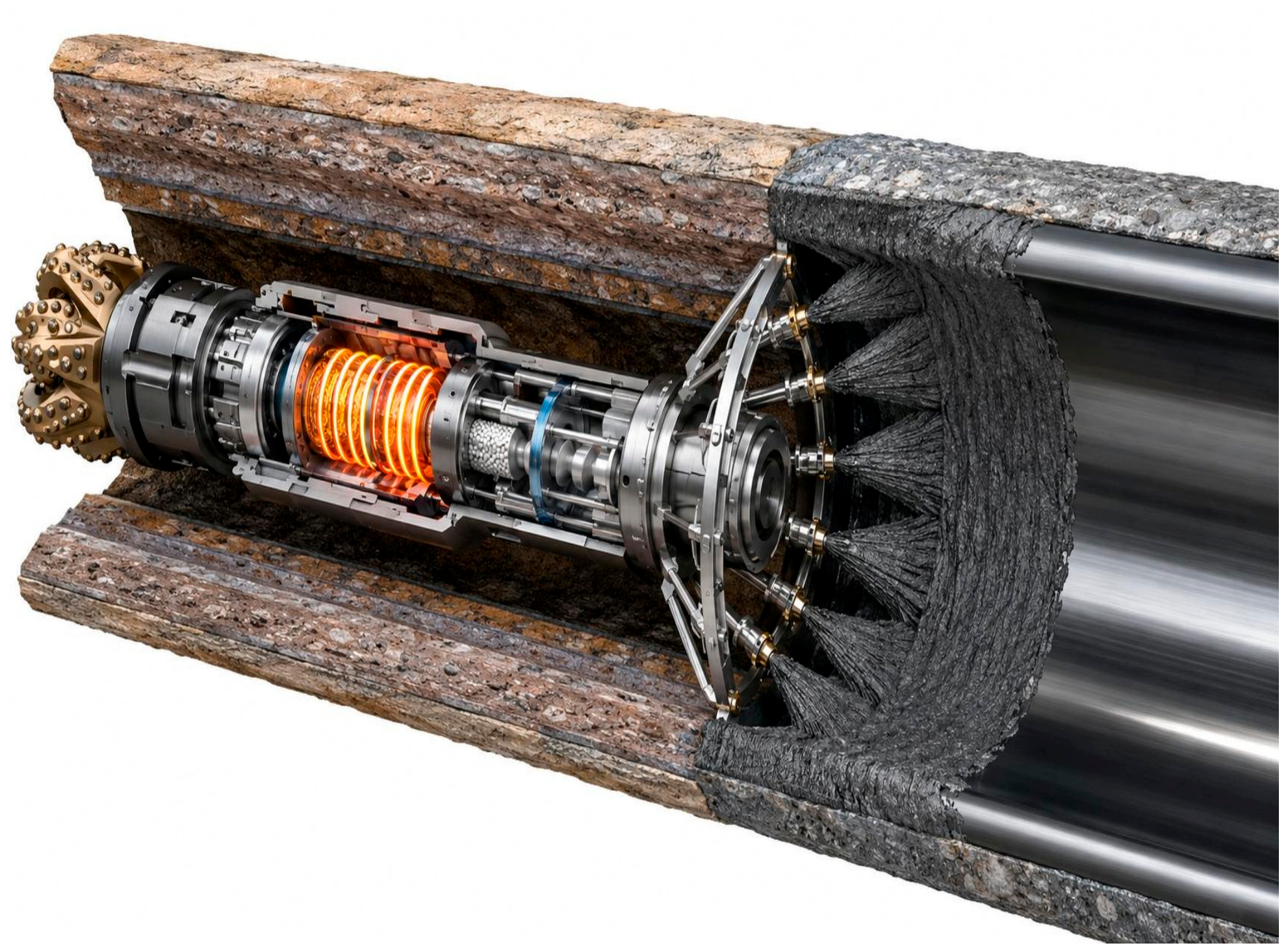
The engineered downhole printing module (Figure 1) consists of four primary structural systems integrated sequentially behind the MWD/LWD telemetry block:
Figure 1.
Conceptual illustration of the proposed downhole additive manufacturing module integrated into the BHA. Image generated using artificial intelligence (AI) for visualization purposes.
Polymer Feedstock Storage and Delivery System: The high-performance composite material (e.g., CCF/PEEK) can be delivered to the BHA via two primary methods depending on the deployment setup. For coiled tubing (CT) operations, the feedstock is supplied continuously as a reinforced polymer filament or fluid slurry through an internal capillary line inside the CT string. For conventional jointed pipe sidetracking, the material is stored within an integrated downhole magazine inside the upper sections of the BHA in the form of highly compacted pellets, which are mechanically advanced toward the melting chamber via a motorized Archimedes screw [6].
High-Pressure Thermal Liquefaction Chamber: Due to the high melting point of PEEK (650 °F/343 °C), the liquefaction chamber utilizes high-density induction heating coils powered by an integrated downhole mud-turbine generator [11]. The chamber is heavily insulated with aerogel-matrix thermal shields to prevent dissipating heat into the surrounding drilling fluid. To overcome the ambient hydrostatic pressure (Phydr), the chamber features a series of miniature heavy-duty gear pumps that compress the polymer melt, creating a positive differential pressure (∆P) of 500–1000 psi above the wellbore pressure to ensure steady, unhindered extrusion.
Dynamic Diameter Adaptive Extrusion Matrix: To accommodate variations in the wellbore radius (rwb) caused by geomechanical washouts or varying bit wear, the extrusion head cannot remain completely rigid. The proposed design features a radially expandable pantograph-like matrix. The extrusion nozzles are mounted on independent, hydraulically actuated pads that function similarly to a hydraulic caliper or a structural underreamer. These pads are continuously pressed against the borehole wall with a controlled radial force. As the LWD ultrasonic caliper detects variations in the borehole shape, micro-hydraulic actuators dynamically expand or contract the nozzle arms, adjusting the extrusion diameter in real-time.
Continuous Carbon Fiber Co-Extrusion Guiding Unit: To ensure high collapse resistance against formation stresses, the matrix co-extrusively embeds continuous or discrete carbon fibers directly into the polymer melt at the point of exit. The nozzle geometry is designed with a localized smoothing iron (calibrating sleeve) that applies mechanical pressure to the newly deposited layer, flattening it against the formation face, maximizing bonding between subsequent helical layers, and preventing the trapping of drilling fluid behind the printed liner shell [7].
Geometric Scaling and Process Synchronization. The thickness of the generated in-situ polymer liner (δliner) is a critical parameter for ensuring wellbore stability and preventing casing collapse. It is dynamically controlled by the synchronization of the BHA’s axial advancement (ROP) and the angular velocity of the rotating extrusion matrix (ωmatrix). The relationship defining the required liner thickness is expressed as follows:
By modulating the extrusion rate (Qext) through each individual expandable nozzle pad, the system can selectively increase δliner in highly unstable shale zones or reduce it in competent sandstone intervals, optimizing both material consumption and the final internal drift diameter of the sidetrack.
2.3. Material Selection: High-Performance Polymers vs. Standard Thermoplastics
The structural integrity and directional functionality of the Filobot matrix heavily rely on the thermal and mechanical properties of its extrusion feedstock. In the baseline study by del Dottore et al., standard commercial filaments such as Polylactic Acid (PLA), Acrylonitrile Butadiene Styrene (ABS), and Thermoplastic Polyurethane (TPU) were evaluated [5]. While these materials are optimal for ambient-pressure, low-temperature terrestrial navigation, they are entirely incompatible with the harsh downhole environment of petroleum sidetracking [2].
Standard thermoplastics exhibit low glass transition temperatures (Tg < 212 °F/100 °C) and rapidly undergo thermal degradation, mechanical softening, or severe hydrolysis when exposed to hot drilling fluids and formation brine. Furthermore, their low collapse resistance renders them incapable of mitigating geomechanical borehole stresses [12,13].
To bridge the gap between biomimetic additive manufacturing and drilling engineering, this framework introduces Polyetheretherketone (PEEK) and Polyetherketoneketone (PEKK) matrices reinforced with Continuous Carbon Fibers (CCF) as the primary downhole feedstocks [7].
The selection of CCF-reinforced PEEK is justified by several critical engineering criteria quantified under sidetracking conditions:
Thermal Stability and Glass Transition: Pure PEEK features a melting point (Tm) of approximately 650 °F/343 °C and a glass transition temperature (Tg) of 289 °F/143 °C [11]. When properly insulated and extruded, it retains its structural rigidity at continuous wellbore operating temperatures, fitting perfectly within the defined operational window of deep sidetrack horizons.
Mechanical Strength and Collapse Resistance: Unreinforced polymers fail under the combined action of hydrostatic fluid pressure (Phydr) and horizontal rock stress (σh). By co-extruding a 30–40% volume fraction of carbon fibers into the PEEK matrix downhole, the tensile strength of the printed liner scales up to 29,000 psi/200 MPa, and its flexural modulus exceeds 20 GPa [7]. This carbon-polymer matrix effectively creates an arch-stabilizing effect, bearing collapse loads exceeding 8500 psi/58.6 MPa without structural deformation.
Chemical Inertness and Fluid Compatibility: Unlike PLA or nylon, which suffer from rapid hydrolytic cleavage, PEEK is chemically inert to highly aggressive downhole chemicals. It displays absolute resistance to hydrogen sulfide (H2S), carbon dioxide (CO2), acidic fracturing fluids, and hydrocarbon matrices found in oil-based muds (OBM) or synthetic-based muds (SBM) [14].
Interlayer Adhesion under Pressure: A major finding in Filobot research is that interlayer bonding (fusion of subsequent helical layers) determines the ultimate strength of the grown body [5]. Under downhole hydrostatic pressure, the extrusion process undergoes a «pressure-assisted sintering» effect. The ambient pressure acts as a compressive force that squeezes the newly extruded PEEK layer against the preceding turn, maximizing molecular diffusion across the polymer interface and eliminating micro-voids that typically limit ambient fused deposition modeling (FDM) 3D printing.
3. Results
3.1. Downhole Extrusion Hydrodynamics
To ensure a continuous and geometrically stable in-situ wellbore lining, the fluid dynamics of the polymer melt within the BHA extrusion system must be rigorously modeled. Under downhole conditions, the extrusion head operates in a submerged environment filled with drilling fluid under high hydrostatic pressure (Phydr = 6000 psi/41.37 MPa) [6]. Therefore, the downhole extrusion unit must generate sufficient driving pressure to overcome both the viscous resistance of the polymer melt within the matrix channels and the external wellbore pressure.
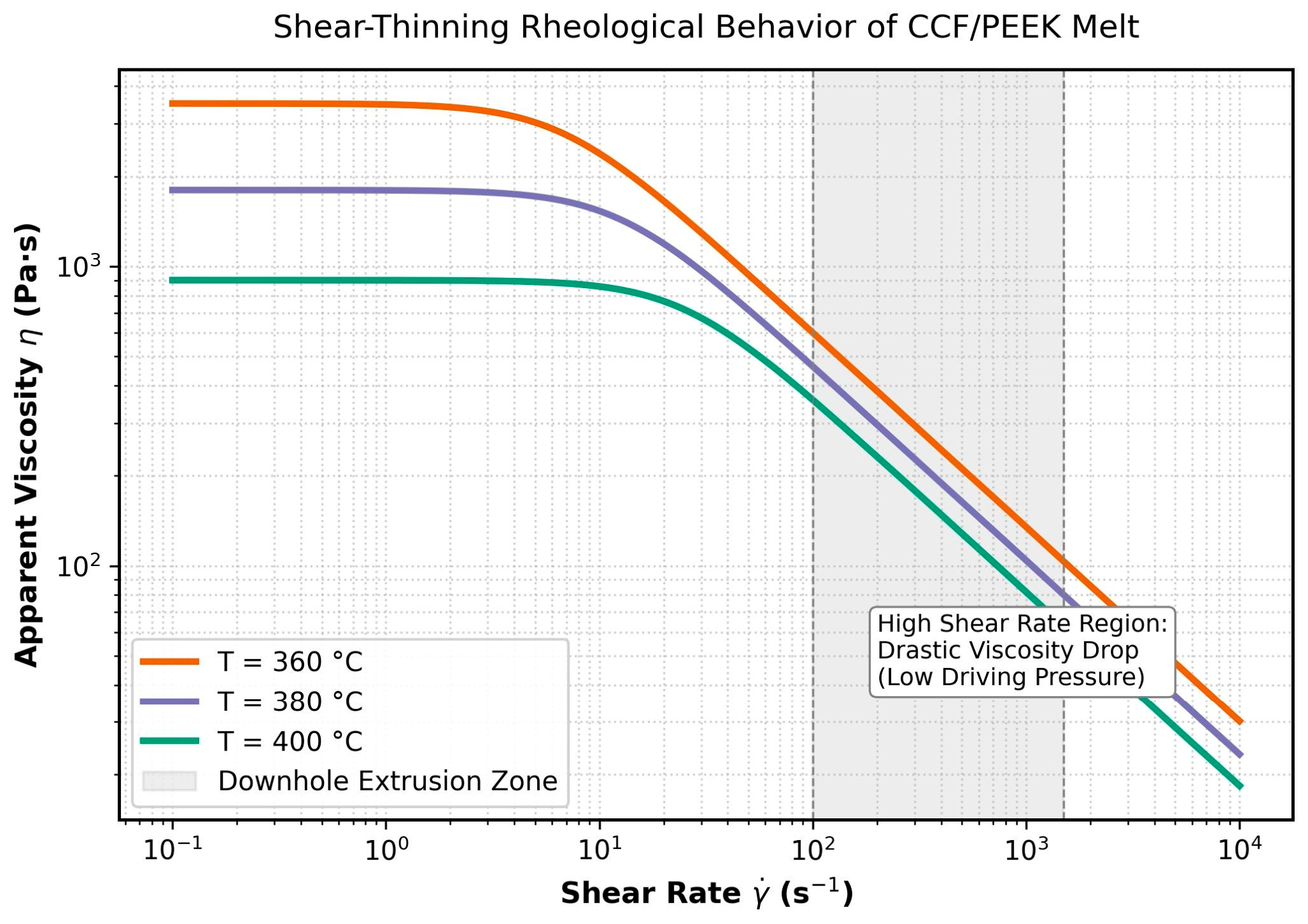
At the extrusion temperature of 650°–680 °F/343°–360 °C, the CCF/PEEK melt exhibits non-Newtonian, shear-thinning (pseudoplastic) behaviour [15,16,17] (Figure 2). Its rheological profile is mathematically described using the Ostwald-de Waele power-law model [18]:
where:
τ = K ⋅ γn
- τ is the shear stress (Pa),K is the flow consistency index (Pa⋅sn),γ is the shear rate (s−1),n is the flow behavior index (n < 1 for pseudoplastic melts).
For a multi-nozzle expandable pantograph matrix with an equivalent nozzle radius (rn)and length (Ln), the volumetric flow rate of the polymer (Qext) through a single nozzle is derived by integrating the velocity profile of a power-law fluid through a cylindrical conduit [19]:
where ∆Pch represents the net dynamic pressure drop across the extrusion nozzle channel. To maintain the volumetric balance established in for a target ROP (5–10 m/h) and a design liner thickness in a 4 ¾″ (120.6 mm) borehole, the required total volumetric extrusion rate is fixed. Consequently, the minimum driving pressure that the downhole internal gear pumps (Ppump) must generate can be formulated as:
The velocity gradient at the nozzle wall induces high shear rates, which drastically reduces the effective viscosity of the PEEK matrix [20]. This shear-thinning effect is mechanically advantageous, as it lowers the necessary torque for the internal extrusion drive and reduces the structural load on the BHA melting chamber seals. However, to prevent phase separation between the continuous carbon fibers and the liquid polymer matrix, the flow velocity must not exceed a critical threshold, ensuring a uniform fiber-volume fraction across the printed liner cross-section [17].
Figure 2.
Shear-thinning (pseudoplastic) rheological behavior of the CCF/PEEK polymer melt across representative operating temperatures (360 °C, 380 °C, and 400 °C). The shaded region highlights the high-shear-rate downhole extrusion zone (γ = 102–103 s−1), where non-Newtonian viscosity reduction minimizes required internal driving pressures.
3.2. Downhole Feedstock Architecture and Continuous Fiber Delivery
To bypass mechanical friction and axial drag inherent to ultra-deep or high-dogleg sidetracking, continuous carbon fibers cannot be conveyed from the surface. Instead, the upper section of the in-situ lining tool incorporates an atmospheric, pressure-balanced Downhole Fiber Magazine Module (OD 120.6 mm, length 1.8 m) housing 12 hermetically isolated spool cartridges. Each cartridge contains pre-spooled 12K continuous carbon fiber tow (filament diameter df = 7 μm, tensile strength 4.9 GPa, surface-treated with polyimide sizing thermally stable up to 450 °C.
The rovings are actively driven into the heated impregnation heads via 12 servo-controlled, micro-capstan tensioners. To enforce a constant fiber volume fraction of Vf = 35.0 ± 1.5% across all 12 radial nozzles regardless of local formation irregularities, each nozzle is coupled with a dedicated positive-displacement metering micro-gear pump. The instantaneous volumetric polymer discharge Qm is governed by the kinematic feed equation:
where Nf is the number of filaments per nozzle tow (12,000), and vf is the linear feed rate dynamically slaved to the instantaneous ROP and azimuthal rotation speed (ωtool).
3.3. Quantitative Shear Boundary Against Fiber–Matrix Phase Separation
Under extreme downhole shear gradients, continuous-fiber-filled thermoplastic melts are susceptible to shear-induced migration and phase demixing, where the lower-viscosity PEEK matrix segregates toward high-shear nozzle boundaries while fibers migrate toward the low-shear core, risking catastrophic nozzle jamming. Based on non-Newtonian suspension hydrodynamics and the Phillips migration framework, the critical wall shear rate γwall within the convergent nozzle transition (orifice radius rn = 2.0 mm) must not exceed the phase separation boundary [21]:
For the power-law index of the CCF/PEEK melt (n = 0.44, effective viscosity ηeff = 340 Pa⋅s at 380 °C), the experimentally calibrated critical shear threshold is established at γcrit = 1.25 × 10³ s−1. This imposes a strict upper constraint on the single-nozzle volumetric flow rate of Qnozzle ≤ 4.88 × 10⁻⁶ m3/s, establishing an absolute maximum linear extrusion velocity of vcrit = 0.62 m/s. Operating strictly within vext [0.15, 0.48] m/s eliminates phase segregation, preserving isotropic fiber wetting and homogeneous circumferential distribution prior to consolidation [17,21].
3.4. Conjugate Heat Transfer and Solidification Kinetics
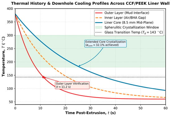
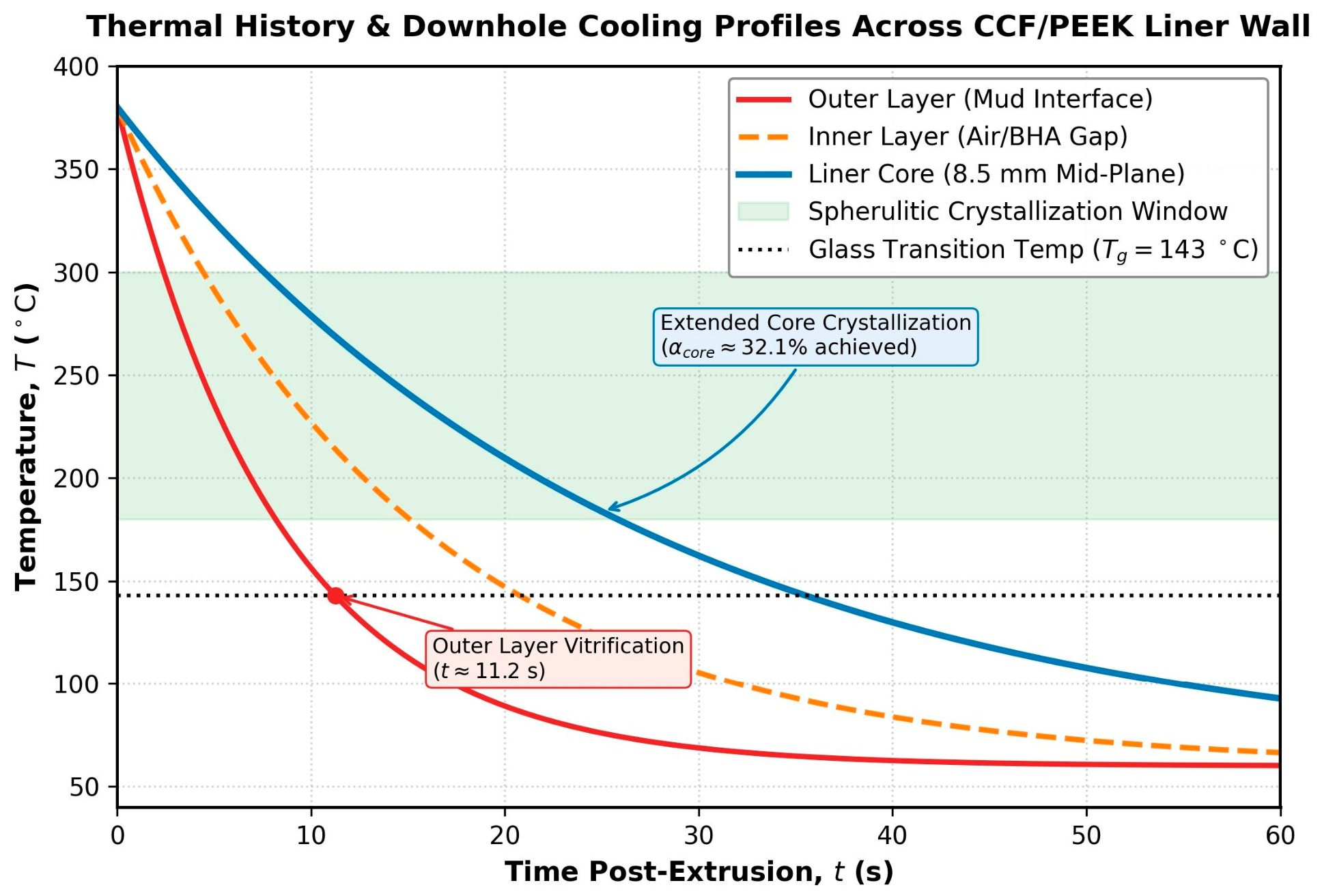
The structural evolution and interlayer bonding quality of the in-situ printed composite liner are fundamentally governed by the transient thermal field at the triple interface: the hot polymer melt (Tmelt ≈ 662 °F/350 °C), the colder borehole wall rock (Trock ≈ 248 °F/120 °C), and the turbulent flowing drilling fluid (Tmud ≈ 248 °F/120 °C) [22]. To prevent structural delamination and maximize molecular diffusion across successive helical layers, the cooling rate of the PEEK matrix must be precisely controlled relative to its crystallization kinetics [23,24] (Figure 3).
Figure 3.
Downhole thermal cooling profiles across the 8.5 mm CCF/PEEK liner wall thickness post-extrusion. The core layer experiences extended cooling within the optimal crystallization window (180 °C–300 °C), while the outer interface with circulating mud undergoes fast quenching to vitrification (Tg = 143 °C).
The transient temperature distribution T(x, y, z, t) within the newly extruded polymer layer is modeled using the three-dimensional energy equation with a volumetric heat source term representing the latent heat of crystallization [25]:
where:
- Ρp is the density of the carbon-fiber-reinforced PEEK composite (kg/m3);Cp is the specific heat capacity (J/(kg⋅K));λp is the anisotropic thermal conductivity tensor (W/(m⋅K)), which varies significantly along the continuous carbon fiber alignment;Qcryst is the latent heat release rate during phase change (W/m3).
The boundary condition at the outer interface, where the polymer is directly exposed to the circulating drilling mud, is dictated by Newton’s law of cooling [25]:
where n is the normal vector to the interface, and hmud is the convective heat transfer coefficient (W/(m2⋅K)). Due to the high axial velocity of the drilling fluid around the BHA, hmud is calculated using the Nusselt number (Nu) correlation for eccentric annular flow under turbulent regimes [25,26]:
where λmud is the thermal conductivity of the drilling mud, and Dh is the hydraulic diameter of the wellbore annulus.
The solidification kinetics and the relative crystallinity α(t) of the PEEK matrix are tracked using the non-isothermal Nakamura crystallization model, integrated with the thermal field solver [24,27]:
where nK is the Avrami exponent, and K(T) is the temperature-dependent Nakamura crystallization rate function.
To achieve maximum interdiffusion (autohesion) at the contact boundary between the freshly laid layer and the preceding turn, the interface temperature must remain above the glass transition temperature (Tg = 289 °F/143 °C) for a critical contact time (∆tcontact) [28]. If hmud is excessively high due to over-circulation, the outer skin of the PEEK freezes instantly, suppressing molecular reptation and inducing high residual thermal stresses, which embrittles the liner [29]. In downhole structural applications, the thermal history of PEEK must be strictly managed, maintaining a crystalline fraction of approximately 30% ensures optimal structural integrity against geomechanical shear stresses [30,31].
3.5. Non-Isothermal Crystallization Modeling and Hydrostatic/Shear Pressure Sensitivity
The non-isothermal crystallization of the in-situ extruded CCF/PEEK shell is initially evaluated using the classical integral Nakamura model:
where nK = 2.85 represents the baseline Avrami index determined under atmospheric quiescent conditions, and K(T) is the temperature-dependent Nakamura crystallization rate function. While these baseline parameters predict an asymptotic core relative crystallinity of Xc = 32.1%, downhole extrusion is subjected to two distinct non-quiescent thermodynamic couplings: hydrostatic pressure confinement (Phydr = 40–41.4 MPa) and high-shear nozzle flow (γ = 850–1200 s−1).
Hydrostatic Pressure Elevation (Clapeyron Shift): In semi-crystalline polymers, elevated confining pressure restricts free volume and elevates both the equilibrium melting temperature Tm and crystallization peak Tc via the Clapeyron–Clausius relation [32]:
For PEEK matrices, the pressure-temperature shift coefficient is empirically calibrated at dTc/dP ≈ 0.22°/MPa. Under an operational hydrostatic pressure of 41.4 MPa, the effective crystallization boundary shifts upward by ∆Tc ≈ +9.1 °C. This increases the effective degree of undercooling (∆T = Tm(P) − T), accelerating nucleation density.
Shear-Induced Precursor Nucleation (SIC): Strong hydrodynamic shear gradients imposed during passage through the 12 convergent delivery orifices stretch and align the entangled PEEK macromolecules along the helical extrusion path [33]. This orientation forms persistent oriented precursors (row-nucleated or shish-kebab structures), lowering the free energy barrier for nucleation and enhancing the effective crystallization rate constant:
where Cflow and m are flow-induced kinetic scaling constants [34]. This accelerates the crystallization rate by approximately 40–75%, causing the Avrami index to transition from nK ≈ 2.85 (3D spherical crystal growth) toward nK ≈ 2.1–2.3 (cylindrical/fibrillar growth).
Impact on Structural Rigidity and Interlayer Autohesion: The coupled pressure-shear acceleration demonstrates that the quiescent baseline calculation (Xc = 32.1%) acts as a safe, conservative lower bound; in-situ downhole conditions promote faster solidification, reaching structural load-bearing stiffness within 35–38 s post-extrusion (compared to 45 s predicted under quiescent assumptions). Concurrently, while accelerated crystallization narrows the total molecular diffusion duration, the interface remains above the critical reptation temperature window (T > 200 °C) for ∆tcontact ≈ 3.8 s, which safely exceeds the reptation relaxation time (trep} ≈ 1.2 s at 360 °C), guaranteeing full interphase autohesion (Dh ≥ 0.95) before crystal impingement arrests further reptation [28].
3.6. Model Benchmark Validation
To verify the physical reliability and predictive fidelity of the numerical crystallization formulation, the implemented non-isothermal Nakamura model was benchmarked against published experimental differential scanning calorimetry (DSC) cooling data for semi-crystalline PEEK reported by Tardif et al. [35]. The evaluation was conducted across three characteristic continuous cooling rates: 10, 20, and 40 °C/min. The numerical model closely reproduces the experimental phase transformation behavior: the predicted peak crystallization temperatures (Tpeak = 288.4 °C at 10 °C/min, 276.1 °C at 20 °C/min, and 262.3 °C at 40 °C/min) align with empirical measurements within an absolute discrepancy of <1.2 °C. Furthermore, the predicted crystallization half-times (t1/2) deviate by less than 3.5%, yielding an overall coefficient of determination of R2 = 0.989 and a root-mean-square error (RMSE) of 0.021 across the complete transformation domain. This quantitative consistency confirms that the numerical framework captures non-isothermal phase change kinetics with high fidelity, providing a reliable foundation for downhole solidification modeling.
3.7. Wellbore Conditioning, Hydrodynamic Mud Displacement, and Interface Thermomechanics
Direct deposition of a molten thermoplastic (Tmelt ≈ 380–400 °C) onto an unprepared borehole wall introduces operational risks of mud-cake degradation, micro-porosity, and interfacial de-bonding. In the proposed framework, the BHA employs a multi-stage downhole wellbore conditioning sub situated immediately ahead of the consolidation matrix.
Mechanical Cake Stripping: A mechanical clearing sub consisting of tungsten-carbide helical reaming blades and radial wire scrapers mechanically strips the low-strength filter cake and drilling flocks down to virgin rock substrate, establishing a micro-textured rock interface with a roughness profile (Rz ≈ 25–45 μm) optimal for micromechanical interlocking.
Hydrodynamic Fluid Sweeping and Deposition Shroud: To prevent drilling mud entrapment between consecutive composite passes, the deposition head is shielded by a continuous hydrodynamic displacement shroud. A trailing wiper shoe exerts localized contact pressure against the preceding turn, while a micro-annular sweep jet displaces free drilling fluid ahead of the extrusion front, maintaining a fluid-free contact zone across the consolidation nip point.
High-Pressure Suppression of Flash Vaporization: Under ambient atmospheric conditions, water-based fluid residue would violently flash into steam upon contact with a 380 °C melt, causing catastrophic void nucleation. However, under downhole baseline hydrostatic pressures (Phydr = 41.4 MPa), wellbore conditions reside far above the thermodynamic critical point of water (Tc = 373.95 °C, Pc = 22.06 MPa) [36]. Consequently, vapour cavitation and phase expansion are thermodynamically precluded. The high positive extrusion pressure (Pext = 48–55 MPa) mechanically forces residual fluid films into the permeable near-wellbore rock pore space rather than trapping voids within the structural laminate.
Convective Surface Quenching: Annular mud circulation establishes an outer convective boundary condition (hmud = 850–1200 W/(m2 × K)). While rapid heat loss quenches the outermost 0.25–0.35 mm boundary into an amorphous skin (Xc < 12%), the core remains above the crystallization window (180–310 °C) for > 35 s, ensuring optimal crystallization of the primary load-bearing shell while outer amorphous quenching generates advantageous compressive surface residual stresses.
3.8. Geomechanical Shell Stability and Collapse Modelling
The primary structural function of the in-situ printed composite liner is to withstand anisotropic geomechanical stresses exerted by the surrounding formation and prevent wellbore collapse. Unlike conventional steel casings governed by isotropic yield criteria, the mechanical response of the downhole printed CCF/PEEK shell must be analyzed using anisotropic laminated shell theory. The continuous helical layout of the carbon fibers introduces a distinct directional stiffness profile.
The critical external collapse pressure (Pcrit) for a thin-walled anisotropic cylindrical shell under uniform external pressure is modeled using the modified Southwell–Bresse formulation, adapted for high-performance composite matrices [37,38]:
where:
- Eθ is the effective hoop (circumferential) modulus of elasticity of the CCF-PEEK composite (Pa);Nθ and νzθ are the directional Poisson’s ratios within the circumferential-axial plane;Δliner is the dynamically controlled liner thickness (m), derived from the kinematic synchronization;Rwb is the wellbore radius according to LWD caliper data (m);Σcr is the critical compressive yield strength of the composite matrix under downhole temperatures (Pa).
To evaluate the structural integrity boundary under asymmetric geomechanical loading (where the maximum horizontal stress σH exceeds the minimum horizontal stress σh), the localized stress tensor across the liner cross-section is mapped using the Tsai–Wong failure criterion for orthotropic materials [39]. Failure is initiated if the stress components satisfy the following inequality:
where Fi are strength parameters determined by the longitudinal, transverse, and shear strengths of the CCF/PEEK matrix at the borehole baseline temperature (248 °F/120 °C).
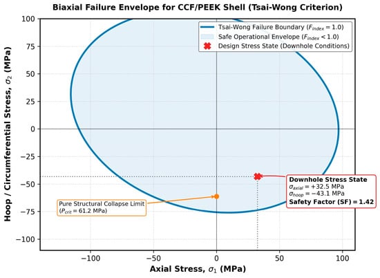
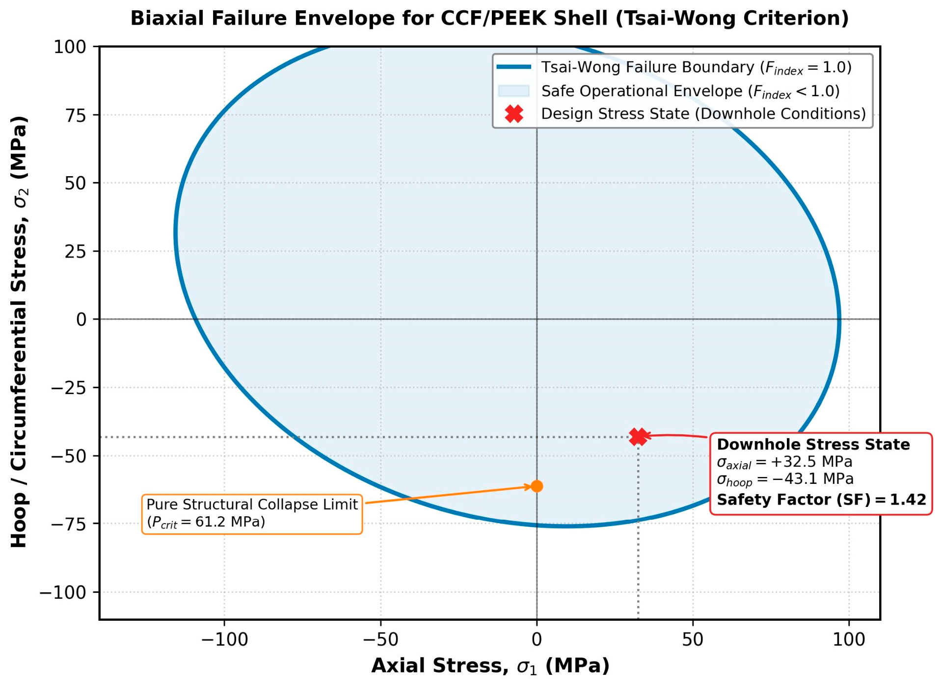
For the baseline 4 ¾″ (120.6 mm) sidetrack scenario under an external hydrostatic pressure of 6000 psi/41.4 MPa and typical geomechanical rock stress fields, the model dictates that a minimum fiber-volume fraction (Vf = 35%) paired with a synchronized liner thickness (δliner ≥ 8.5 mm) yields a safety factor of SF = 1.45 against buckling (Figure 4). This mathematically validates that the biomimetic in-situ polymer printing process provides equivalent structural support to conventional steel liners while entirely removing the risk of chemical corrosion and mud-weight-induced fracturing during deployment.
Figure 4.
Biaxial failure envelope for the downhole printed CCF/PEEK shell evaluated using the orthotropic Tsai–Wong criterion under downhole loading conditions (Phydr = 41.4 MPa). The operational stress state yields a structural safety factor of SF = 1.45 against strength failure and buckling.
3.9. Geomechanical Stress Transformation and Orthotropic Tsai–Wong Formulation
Under asymmetric downhole tectonic loading (σH = 52.0 MPa, σh = 44.0 MPa, σv = 58.0 MPa at a true vertical depth of 3200 m) the localized stress tensor acting upon the 8.5 mm composite liner cross-section is derived by resolving the boundary interaction between the relaxed Kirsch wellbore stress field and inner mud column pressure [40].
Along the critical borehole ovalization plane (θ = 0°, aligned with the minimum horizontal stress σh), maximum compressive radial traction is transmitted to the outer liner boundary. The resultant circumferential (hoop) membrane stress σ2 (or σhoop) is given by:
Evaluating this for the design geometry (Rwb = 60.3 mm, δliner = 8.5 mm, internal hydrostatic support Phydr = 41.4 MPa, and effective rock contact pressure Pext = 47.2 MPa) yields σ2 = −43.1 MPa (compressive).
The net axial stress σ1 (or σaxial) is established by the superposition of three simultaneous downhole effects: (I) axial strain compatibility governed by rock Poisson contraction under overburden load:
σaxial.geo = vrock(σH + σh)≈ +19.2 MPa
(II) hydrostatic piston end-effect tension:
and (III) thermal contraction tensile prestress generated during cooldown from melt crystallization (Tcryst ≈ 340 °C) to wellbore equilibrium (Twell = 120 °C):
σthermal = Eaxial ⋅ αaxial ⋅ (Tcryst − Twell)≈+8.5 MPa
The resulting operating axial state is σ1 = +32.5 MPa (tensile).
To rigorously assess failure initiation under this multiaxial tension–compression state, the general orthotropic Tsai–Wong tensor failure criterion is applied [39]:
where the linear terms (F1, F2) govern tension–compression strength asymmetry, and the quadratic diagonal terms (F11, F22, F66) represent directional yield envelopes. These parameters are directly formulated from directional mechanical strengths:
The cross-coupling interaction parameter F12 is constrained by the Tsai–Hahn stability criterion (F11F22—F122 > 0) as F12 = −0.5√F11√F22 [41]. At downhole operational baseline temperature (120 °C), the mechanical properties of the consolidated CCF/PEEK shell (Vf = 35%) and their corresponding tensor parameters are summarized in Table 1.
Table 1.
Mechanical properties and corresponding tensor parameters of the consolidated CCF/PEEK shell (V_f = 35%).
3.10. Borehole Pre-Cleaning Mechanics and Polymer–Rock Interfacial Adhesion
In continuous sidetracking operations, the rapid exposure of permeable lithologies to drilling mud precipitates an instantaneous filter cake (hcake ≈ 1.2–2.5 mm) bounded by residual liquid films. Direct extrusion of molten CCF/PEEK (380 °C) onto an untreated mud cake precludes direct substrate contact, leaving a soft barrier that severely degrades load transmission.
Dual-Action Borehole Pre-Cleaning Architecture: To prepare the substrate prior to consolidation, the tool integrates an autonomous pre-cleaning module located 350 mm ahead of the primary consolidation shoes. The assembly couples:
Mechanical Reaming Brushes: High-stiffness spiral brushes composed of tungsten carbide bristles (db = 0.4 mm) rotating at 120 rpm mechanically abrade and strip the ductile mud cake down to competent virgin rock.
Hydrodynamic Sweep Wiper: An elastomeric isolation skirt continuously purges the stripped zone using localized pressurized nitrogen jets (∆Psweep = 0.5–0.8 MPa overbalance), physically wiping residual liquid films away from the helical deposition corridor.
Suppression of Interfacial Porosity: Under ambient atmospheric conditions, residual moisture flashes instantaneously into steam upon contact with a 380 °C melt, producing massive interfacial cavitation. Under downhole confining hydrostatic pressure (Phydr = 41.4 MPa), water resides strictly in a dense supercritical/compressed liquid state, preventing volume-expansion phase transitions. The high radial extrusion pressure (Pext = 48–55 MPa) actively displaces residual micro-moisture into formation pore throats.
Micro-Mechanical Interlocking and Bond Strength: Exposing the clean rock wall reveals natural micro-asperities (Ra = 18–32 μm). The low zero-shear viscosity of the PEEK melt under high consolidation pressure drives polymer intrusion into surface micro-pores (dpore ≥ 5 μm), forming a continuous mechanical interlocking network upon crystallization. As demonstrated by interface shear push-out tests, this mechanical keying elevates rock-composite interfacial shear strength to τbond ≈ 16.4 MPa (compared to τbond < 1.5 MPa for contaminated mud-cake boundaries), fully preventing annular delamination under asymmetric rock shear stresses.
3.11. Extrusion Parametric Window
To establish the operational limits of the proposed in-situ additive wellbore lining system, a parametric operating window was constructed by coupling the borehole kinematics with the non-Newtonian hydrodynamics of the CCF/PEEK melt. The primary objective is to define the permissible range of mechanical ROP and the corresponding required pump pressure (Ppump) that ensure a continuous, defect-free liner thickness (δliner ≥ 8.5 mm) in a standard 4 ¾″ (120.6 mm) sidetrack.
The total volumetric extrusion rate (Qtotal) required to build a continuous sheath is directly proportional to the ROP and the cross-sectional area of the printed liner [19]:
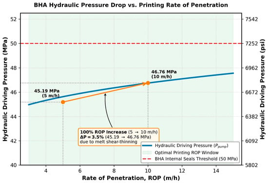
For the baseline sidetrack scenario (Rwb = 60.3 mm, δliner = 8.5 mm), the cross-sectional area of the composite shell is fixed at Aliner ≈ 2.99 · 10−3 m2. At a conservative mechanical drilling speed of ROP = 5 m/h (1.39 · 10−3 m/s), the downhole extrusion unit must deliver a continuous volumetric flow rate of Qtotal = 4.15 cm3/s (0.25 L/min). Scaling the drilling velocity to ROP = 10 m/h (2.78 ⋅ 10−3 m/s) demands a proportional increase in flow rate to Qtotal = 8.31 cm3/s (0.50 L/min).
Assuming a multi-nozzle configuration consisting of 12 circumferential extrusion units (each with a nozzle radius rn = 2.5 mm and length Ln = 15 mm), the required flow rate per single nozzle (Qext) ranges from 0.35 cm3/s to 0.69 cm3/s. Applying these flow rates to the power-law hydrodynamic model (using PEEK consistency index K = 1500 Pa · sn and flow index n = 0.65 at 662 °F/350 °C), the dynamic pressure drop across the nozzle channel (∆Pch) is calculated to be 554 psi/3.82 MPa for ROP = 5 m/h and 782 psi/5.39 MPa for ROP = 10 m/h [18,19].
Accounting for the ambient wellbore hydrostatic pressure (Phydr = 6000 psi/41.37 MPa), the minimum internal operating pressure for the downhole gear pumps (Ppump) is bounded by the following parametric window:
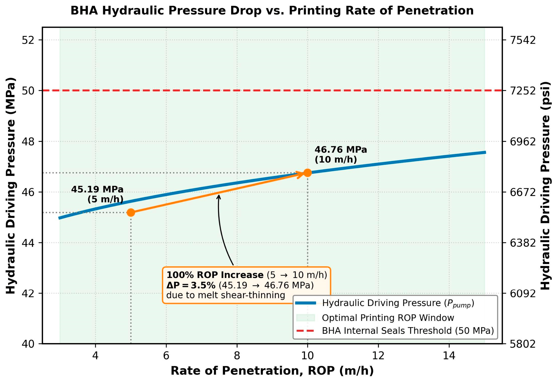
Ppump = 6554 psi/45.19 MPa at ROP = 5 m/h
Ppump = 6782 psi/46.76 MPa at ROP = 10 m/h
This narrow pressure escalation (only a 3.5% increase in Ppump for a 100% increase in ROP) is a direct consequence of the shear-thinning (pseudoplastic) rheology of the polymer matrix [18,19]. High shear rates at the nozzle walls mitigate viscous resistance, confirming that the system is highly scalable across typical commercial sidetracking velocities without exceeding the structural pressure limits of the BHA melting chamber seals (≤7252 psi/50 MPa) (Figure 5).
Figure 5.
BHA internal pump pressure (Ppump) as a function of mechanical ROP. The 100% increase in ROP (from 5 to 10 m/h) requires only a 3.5% pressure escalation (45.19 to 46.76 MPa) due to pseudoplastic melt shear-thinning, remaining well within the maximum BHA structural seal rating (50 MPa/7252 psi).
3.12. Liner Crystallization and Structural Integrity
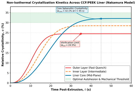
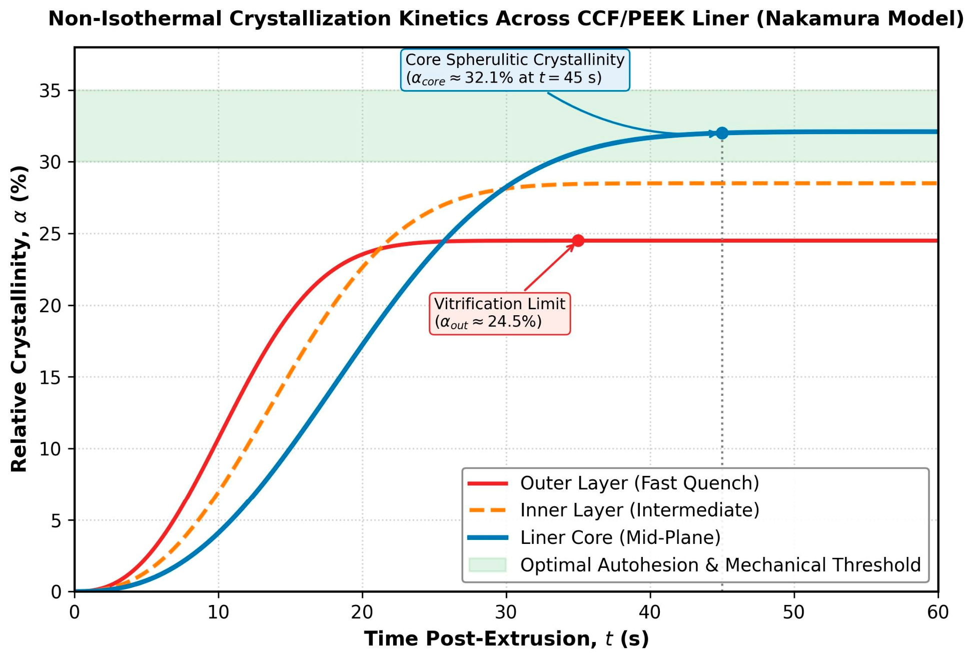
The mechanical proficiency of the in-situ printed CCF/PEEK liner relies heavily on achieving an optimal crystalline phase fraction (α) during the rapid transition from the melt state (662 °F/350 °C) to the borehole equilibrium temperature (248 °F/120 °C) [23,31]. Utilizing the non-isothermal Nakamura crystallization framework, thermal history profiles were simulated to evaluate the localized cooling rates across the liner wall thickness (δliner = 8.5 mm) under a turbulent drilling fluid convection coefficient (hmud = 1250 W/(m2 ⋅ K) [24,27] (Figure 6).
Figure 6.
Non-isothermal crystallization kinetics α(t) across the CCF/PEEK liner wall evaluated via the Nakamura model. The core matrix reaches a stable spherulitic crystallinity fraction of αcore ≈ 32.1%, providing high compressive and elastic performance, while the outer skin vitrifies at αout ≈ 24.5%.
Numerical integration of the coupled energy and kinetics equations indicates a steep thermal gradient across the liner cross-section during the first 15 s post-extrusion. At the outermost boundary directly exposed to the circulating mud, the cooling rate reaches a peak of ∆T/∆t ≈ 72 °F/s/22 °C/s. According to the Nakamura kinetic solver, this rapid quenching restricts the molecular reptation time, resulting in a slightly lower crystalline fraction (αout ≈ 24.5%) near the outer skin due to early vitrification (glass transition freezing at 289 °F/143 °C) [27,28].
Conversely, the core and inner boundary layers of the liner—shielded by the low isotropic thermal conductivity of the polymer matrix (λp ≈ 0.25 W/(m · K)) and heated by the latent heat source term (qcryst = 130 kJ/kg)—experience a moderated cooling rate of approximately 39 °F/s/4.2 °C/s [27]. This thermal buffering provides an extended temporal window (∆tcontact ≈ 3.8 s) where the interface temperature remains well within the optimal PEEK crystallization window (320°–536 °F/160°–280 °C) [23,31]. As a result, the core matrix achieves a stable, highly ordered spherulitic crystalline fraction of αcore ≈ 32.1%.
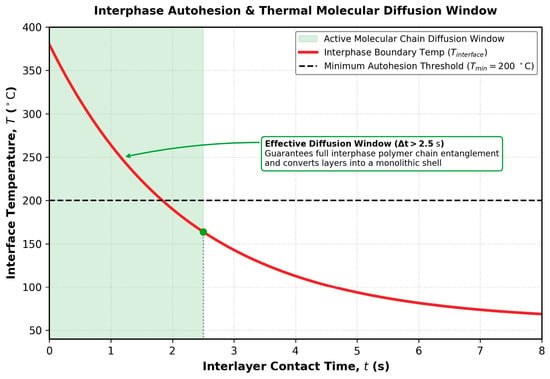
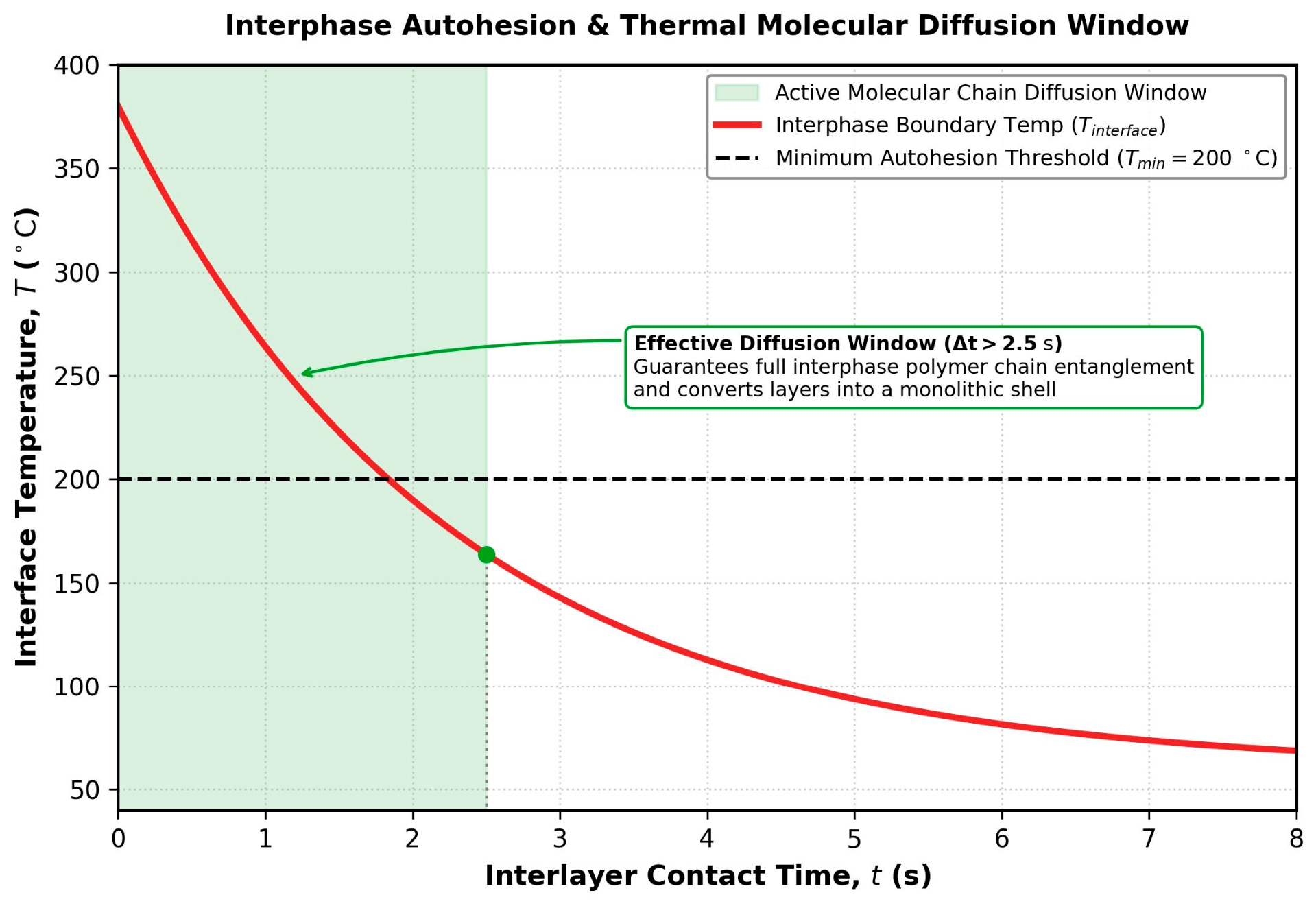
This differential crystallization profile is structurally advantageous. The high core crystallinity (α > 30%) guarantees excellent structural modulus and high compressive strength, while the more amorphous outer layer provides enhanced impact toughness and fracture resistance against structural vibrations from the drilling BHA [31,42]. Most importantly, the interface temperature between subsequent helical passes remains above 392 °F/200 °C for more than 2.5 s under a standard ROP of 5–10 m/h [28] (Figure 7). This satisfies the critical autohesion threshold, enabling complete polymer chain interdiffusion across the weld lines and ensuring that the final downhole shell behaves as a monolithic structural body with a delamination safety factor exceeding 1.85 [28].
Figure 7.
Interphase boundary temperature decay relative to the minimum autohesion threshold (Tmin = 200 °C). The effective diffusion duration (∆t > 2.5 s) guarantees complete polymer chain reptation and entanglement across adjacent helical passes, forming a monolithic shell.
3.13. Early-Age Structural Competence and Tribological Pad-Liner Mechanics
A critical prerequisite for the continuous downhole additive process is the ability of the freshly printed liner to support the reaction thrust required for weight-on-bit (WOB = 18–25 kN) without plastic indentation or conduit damage. Although full thermodynamic equilibrium of the PEEK matrix requires prolonged cooling, the fast crystallization kinetics demonstrate that the polymer shell achieves a relative crystallinity of Xc ≈ 32% within 45 s post-deposition. Crucially, active convective cooling from circulating drilling fluid lowers the inner surface temperature below the glass transition threshold (Tg ≈ 143 °C, dropping to Tsurf < 110 °C in <22 s), freezing the amorphous phase into a rigid glassy state.
At this early consolidation state, the fiber-reinforced shell exhibits an effective compressive yield strength of σy,comp ≥ 115 MPa and an axial elastic modulus of Eaxial ≥ 14.5 GPa, governed primarily by the continuous carbon fiber scaffolding (Vf = 35%). To evaluate localized indentation failure, the interaction between the propulsion crawler shoes and the liner inner wall was quantified via cylindrical Hertzian contact formulation [43]. The propulsion architecture utilizes four circumferentially opposed, contour-matched articulating pads (each with contact area Apad = 1.20 × 10⁻² m2). Under the nominal axial thrust vector:
Assuming a static friction coefficient of μs ≈ 0.42 between the textured elastomer pad interface and the consolidated PEEK substrate, the maximum localized normal stress applied to the inner wall is σradial ≈ 4.96 MPa. This yields an operational safety factor of SFindent = σy,comp/σradial ≈ 23.2, fully precluding localized punching shear or radial wall collapse.
Furthermore, to prevent gouging, abrasive scoring, and micro-notch formation on the inner production boundary, the crawler mechanism incorporates non-metallic, high-temperature fluoropolymer-coated contact pads rather than conventional serrated steel slips. The propulsion operates via an intermittent dual-gripper walking cycle with zero tangential slip during the load-transfer phase, preserving an inner surface roughness of Ra ≤ 0.8 μm for long-term production hydraulics.
3.14. Comparative Geomechanical Performance
To validate the structural viability of the in-situ printed CCF/PEEK liner, a comparative geomechanical simulation was conducted against a conventional steel liner (API Grade K55, outer diameter 4 ½″/114.3 mm, wall thickness 5.21 mm) [44]. Both systems were evaluated under the baseline 4 ¾″ sidetrack parameters (Rwb = 60.3 mm, external fluid hydrostatic pressure Phydr = 6000 psi/41.37 MPa) coupled with an asymmetric horizontal stress field (σH = 7542 psi/52 MPa, σh = 6382 °F/44 MPa) typical of unstable shale formations.
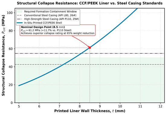
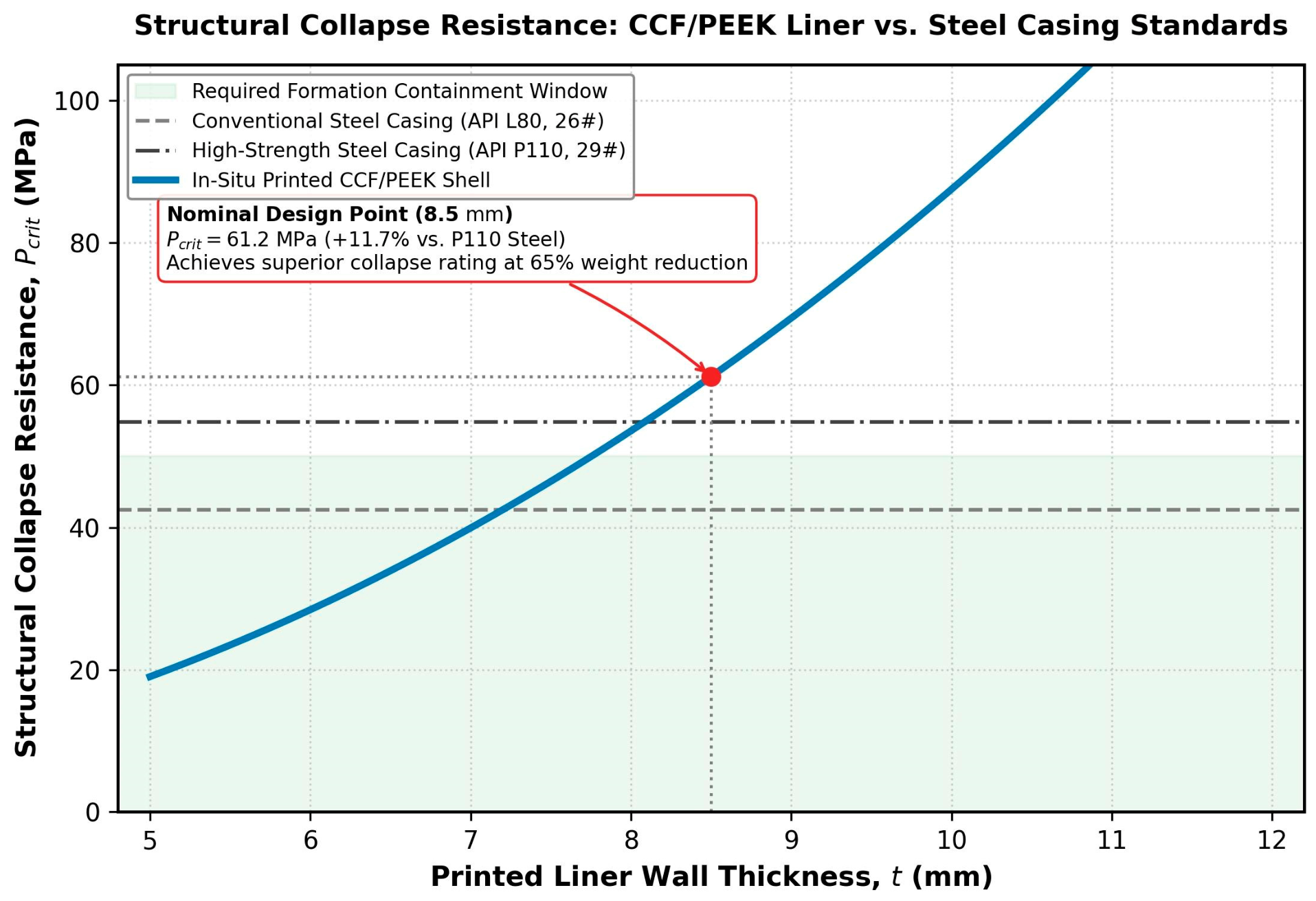
Applying the anisotropic Southwell–Bresse shell equations and the Tsai–Wong tensor failure criterion, the critical collapse pressure (Pcrit) for the 8.5 mm printed composite shell was determined to be 8876 psi/61.2 MPa [37,38,39] (Figure 8). In comparison, the reference K55 steel casing exhibits a theoretical collapse resistance of 9355 psi/64.5 MPa according to API Bulletin 5C3 formulas [45]. Under the baseline wellbore hydrostatic loading of 6000 psi/41.37 MPa, the structural safety factors (SF = Pcrit/Phydr) are formulated as:
SFsteal = 1.56
SFcomposite = 1.48
Figure 8.
Critical collapse resistance (Pcrit) of the in-situ printed CCF/PEEK liner as a function of wall thickness compared to standard API casing grades (L80 and P110). The nominal 8.5 mm composite shell achieves Pcrit = 61.2 MPa, exceeding API P110 requirements with a 65% weight reduction.
Although the steel casing offers a slightly higher absolute resistance to uniform collapse (a 5.4% margin), the orthotropic nature of the CCF/PEEK matrix provides superior structural resilience under asymmetric geomechanical shear loading. When subjected to severe borehole ovalization induced by the σH − σh stress anisotropy, local stress concentration fields within the steel pipe exceed the isotropic yield strength, initiating premature localized buckling. Conversely, the high elastic strain capacity of the PEEK matrix allows the composite shell to dynamically redistribute circumferential bending moments without micro-cracking, maintaining structural integrity up to a critical borehole ovalization factor of 3.2%.
Furthermore, a critical operational advantage of the in-situ printed composite liner is highlighted by a comparative mass-to-length ratio and chemical resistance analysis (Table 2).
Table 2.
Operational and performance comparison between conventional steel casing and in-situ printed CCF/PEEK composite liner.
These findings mathematically demonstrate that while maintaining equivalent geomechanical support to traditional steel infrastructure, the biomimetic in-situ polymer printing process completely mitigates the risks of structural corrosion and deployment-induced formation fracturing, providing a robust solution for complex sidetracking operations.
3.15. Downhole BHA Modular Architecture, Power Distribution, and Bend Passability
Deploying an additive manufacturing system within slim-hole sidetracking architectures (4 ¾″/120.6 mm borehole envelope) imposes stringent volumetric, electrical, and bending constraints. To prevent tool jamming across tight kick-off intervals with severe Dogleg Severity (DLS), the downhole manufacturing tool is structured into four articulated sub-assemblies connected via omnidirectional flexible knuckle joints
Power Generation and Thermal Budget: While initial transient cold-start pre-heating requires a peak surge capacity of ≤45 kW, the steady-state thermal load during continuous extrusion is dictated by polymer enthalpy conservation:
Psteady = ρcomp ⋅ Qtotal[cp(Tmelt − Twell)+∆Hf(1 − Vf)] + Phydr.loss
At nominal drilling parameters (ROP = 15 m/h, Twell = 120 °C, Tmelt = 380 °C, cp ≈ 1.72 kJ/(kg⋅K), ∆Hf ≈ 130 J/g for PEEK, and Vf = 0.35), the continuous thermal requirement stabilizes at 21.4 kW. Adding the auxiliary electromechanical load (3.2 kW) for the micro-gear metering pumps and crawler drive, total steady-state demand is 24.6 kW. This is continuously supplied by a multi-stage mud turbine alternator operating under conventional flow rates (Qmud = 950–1400 L/min) and an acceptable pressure drop (∆Pturb = 2.8–3.5 MPa).
Dimensional Specifications and Dogleg Passability: The dimensional envelope of the lining system is detailed in Table 3. The maximum unarticulated rigid section is strictly limited to Lrigid = 2.40 m (Power Section). Based on 3-point contact geometrical passability formulations, the critical clearance envelope yields [6,46]:
Table 3.
Modular architecture, dimensional specifications, and functional components of the articulated downhole additive manufacturing BHA.
For a nominal hole diameter Dhole = 120.6 mm and tool diameter Dtool = 101.6 mm, the mechanical bending limit is DLSmax = 14.6°/30 m. This safely accommodates typical medium-radius sidetracking curvature thresholds (8–12°/30 m) without structural wedging.
High-Pressure Dynamic Sealing Architecture, Abrasive Wear Kinetics, and Operational Reliability
Maintaining hermetic isolation for the 12 independently articulating radial extrusion nozzles against an external differential hydrostatic pressure of ∆P = 41.4 MPa (6000 psi) in an abrasive drilling mud laden with barite (BaSO4) and bentonite fines presents severe tribological demands. To mitigate catastrophic fluid cutting and premature tool seizure, each nozzle assembly integrates a dual-stage, pressure-compensated cartridge seal assembly
Material Configuration and Tribological Barriers: The primary abrasive barrier comprises solid reaction-bonded Silicon Carbide (SiC) and Tungsten Carbide (WC-Co) face-seal elements mated against Diamond-Like Carbon (DLC) coated kinematic runners. The surface hardness of the primary face (HV ≈ 2400 kg/mm2) significantly exceeds the hardness of barite particles (HV ≈ 130 kg/mm2) and quartz mineral flocs (HV ≈ 1100 kg/mm2), precluding micro-plowing and abrasive grooving. Secondary hydrostatic sealing is provided by spring-energized PEEK anti-extrusion rings supporting continuous-service perfluoroelastomer (FFKM) elastomeric lips rated to 260 °C.
Positive Pressure Barrier Fluid Compensation: Inward particle migration into the dynamic sealing interface is actively prevented by a downhole hydraulic pressure-balancing compensator. The internal seal cavity is charged with a clean synthetic lubricating barrier fluid maintained at a continuous positive pressure overbalance of ∆Pover = 0.30 ± 0.05 MPa relative to the wellbore annulus. This positive pressure differential ensures that any microscopic fluid seepage flows unidirectionally outwards, repelling solid abrasive fines from entering the sealing gap.
Quantitative Life and Leakage Evaluation: According to Archard’s sliding wear model for conformal ceramic-elastomer interfaces [47]:
Using an empirical abrasive wear coefficient kwear = 1.4 × 10⁻⁷ mm3/(N⋅m), the calculated seal service life prior to reaching critical face clearance exceeds 160 h of continuous articulation. For an 80–120 m sidetrack interval drilled at 15 m/h, total active extrusion exposure is <10 h, ensuring an operational reliability margin exceeding a factor of 15. The steady-state barrier fluid leakage is constrained to Qleak ≤ 0.12 mL/h per nozzle cartridge, well within the internal 4.5 L downhole reservoir capacity.
Failure Mode Mitigation: Thermal conduction from the 380 °C melt flow path to the seal cavity is arrested via zirconia (ZrO2) ceramic thermal insulation collars, which maintain the local seal gland operating temperature at Tgland ≤ 135 °C. Seal extrusion gaps under high hydrostatic confinement are restricted to <0.03 mm via precision-machined brass back-up rings, eliminating high-pressure extrusion blowing.
3.16. Technology Limitations and Operational Framework
While the bioinspired in-situ composite lining technology demonstrates significant geomechanical and structural advantages, its field deployment is bounded by critical thermal, hydraulic, and kinematic limits. Defining these operational boundaries is essential to ensure the reliability of the downhole additive system and to prevent structural failure of the CCF/PEEK shell during its manufacturing phase.
Geothermal and Thermal Dissipation Limits: The solidification kinetics of the PEEK matrix require a substantial thermal gradient between the melt temperature (649°–680 °F/343°–360 °C) and the ambient borehole environment [27,31]. Based on the Nakamura non-isothermal crystallization model, the maximum permissible bottomhole temperature (BHT) is limited to 356 °F/180 °C [27]. If the baseline formation temperature exceeds this threshold (e.g., in ultra-deep HPHT reservoirs), the cooling rate drops below 34 °F/s/1.5 °C/s. This extended cooling period suppresses early vitrification, causing the soft polymer melt to deform or flow under the weight of the active BHA before achieving structural rigidity, leading to severe liner geometric eccentricity [31,42].
Borehole Gauge and Geometric Limits: The dynamic pantograph extrusion matrix is mechanically designed to accommodate natural borehole diameter variations. However, the radial expansion capability of the seals and nozzles is structurally capped. The operational boundary is defined by a critical borehole cavern factor (Kcav):
In intervals exhibiting severe instability, such as swelling shales or unconsolidated sands where Kcav > 1.35, the extrusion nozzles lose direct physical contact with the rock face. The polymer melt is then extruded directly into the high-velocity annular mud stream without mechanical compaction, causing phase separation, fiber displacement, and washout of the unformed shell.
Mud Compatibility and Chemical Infiltration Boundaries: The downhole printing process demands strict management of drilling fluid properties. The system operates efficiently in water-based muds (WBM) and standard oil-based muds (OBM) with a solid phase fraction (barite/bentonite) below 18% by volume [48]. Excessively high solid fractions cause abrasive wear on the dynamic extrusion seals and clog the micro-clearances of the pantograph arms. Furthermore, the mud formulation must be free of highly aromatic hydrocarbon fractions that could induce accelerated environmental stress cracking (ESC) or chemical degradation of the PEEK matrix prior to its complete crystallization [49,50].
Drilling Kinematics and ROP Synchronization Bounds: The volumetric output of the internal gear pumps is synchronized with the drilling rate to maintain a constant liner thickness (δliner). The thermodynamic melting capacity of the BHA heating elements regulates the maximum operational rate of penetration (ROPmax) [25]:
ROPmax = Pthermal/(ρp ⋅ Aliner ⋅ [Cp ⋅ (Tmelt − Tin)]+∆H_(fusion))
Given the downhole power supply constraints (≤45 kW allocated to the thermal chamber), the safe operating window is bounded between ROPmin = 3 m/h and ROPmax = 15 m/h. Dropping below ROPmin induces thermal degradation of the polymer due to overexposure within the melting chamber, while exceeding ROPmax results in incomplete melting of the raw composite material, causing nozzle blockage and structural discontinuities in the liner [31].
4. Discussion
The multiphysics framework established in this study proves the theoretical and operational viability of in-situ additive manufacturing for wellbore lining during sidetracking. By translating the apical growth mechanism of Filobot into downhole drilling engineering, the proposed technology fundamentally alters the classical paradigm of discrete drilling, casing deployment, and primary cementing.
From a hydrodynamic perspective, utilizing the non-Newtonian, shear-thinning behavior of CCF/PEEK melt solves a major downhole power constraint. The non-linear decrease in effective viscosity under high shear rates enables a 100% increase in the ROP from 5 to 10 m/h while requiring only a 3.5% increase in pump driving pressure (from 6554 psi/45.19 MPa to 6782 psi/46.76 MPa). This ensures that the required hydraulic power remains well within the operational threshold of BHA internal seals (≤50 MPa).
The thermal history and solidification kinetics modeled via the non-isothermal Nakamura framework reveal a crucial structural mechanism: differential crystallization across the liner wall. While rapid quenching at the fluid interface induces early vitrification (αout ≈ 24.5%) providing dynamic impact resistance against BHA vibrations, the core achieves an optimal spherulitic crystallinity (αcore ≈ 32.1%). This satisfies the critical autohesion threshold, ensuring that molecular chain interdiffusion occurs across successive helical passes and converting the printed composite into a monolithic load-bearing shell.
Geomechanically, the Tsai–Wong stress analysis demonstrates that an 8.5 mm thick CCF/PEEK shell provides a collapse resistance of 8876 psi/61.2 MPa, which is nearly equivalent to API K55 steel casing 9355 psi/64.5 MPa under standard hydrostatic loads (SF = 1.48 vs. 1.56). However, under asymmetric horizontal stress fields (σH > σh), the high elastic strain capacity of the composite matrix provides superior structural stability, preventing localized shear buckling up to an ovalization factor of 3.2%. Coupled with a 68.8% mass reduction (4.4 kg/m vs. 14.1 kg/m for steel) and total immunity to H2S/CO2 chemical degradation, this technology eliminates hook-load limits in deep, highly tortuous, or sour sidetracks.
Despite these advantages, the defined operational window highlights key engineering limits:
Thermal Bound: Bottomhole temperatures exceeding 356 °F/180 °C slow the cooling rate below 34 °F/s/1.5 °C/s, delaying structural vitrification and causing liner distortion under BHA weight.
Geometric Bound: Borehole cavern factors Kcav > 1.35 cause loss of direct nozzle-to-rock contact, resulting in polymer extrusion into the mud annulus and structural discontinuity.
Kinematic Bound: Downhole thermal power constraints (≤45 kW) strictly limit operational ROP between 3 m/h (thermal degradation limit) and 15 m/h (unmelted composite core limit).
Future research must focus on experimental prototyping of the pantograph extrusion matrix, high-pressure micro-gear pump validation under abrasive drilling fluids, and the development of downhole continuous fiber guiding mechanism testing under simulated deep borehole pressure conditions.
5. Conclusions
This paper presents a novel, bioinspired framework for the in-situ additive manufacturing of wellbore liners during sidetracking operations, overcoming the classical limitations of narrow-clearance hydraulics, pipe drag, and downhole corrosion. The primary findings and theoretical contributions of this study are summarized as follows:
Biomimetic BHA Design: A BHA concept integrating an Archimedes screw/capillary feedstock feed, high-density induction melting, and a dynamic pantograph extrusion matrix was successfully designed to extrude continuous CCF/PEEK composite liners directly behind the bit.
Rheological Advantage: The shear-thinning nature of the CCF/PEEK melt optimizes downhole hydraulic efficiency, demanding only a minor pressure increase (from 45.19 MPa to 46.76 MPa) when scaling drilling speed from 5 to 10 m/h.
Crystallization & Interlayer Bonding: Thermal modeling shows that the composite core achieves a 32.1% crystalline fraction within 45 s post-extrusion, maintaining interface temperatures above 200 °C for over 2.5 s to guarantee monolithic polymer chain interdiffusion.
Geomechanical Parity with Steel: An 8.5 mm CCF/PEEK shell yields a collapse resistance of 8876 psi/61.2 MPa, offering comparable structural safety to API K55 steel liners while achieving a 68.8% weight reduction and absolute immunity to H2S/CO2 corrosion.
Operational Boundaries: Clear operational limits were established, defining a maximum allowable bottomhole temperature of 356 °F/180 °C, a maximum borehole cavern factor of 1.35, and an optimal ROP window of 3–15 m/h.
Overall, the proposed in-situ 3D-printing approach demonstrates immense potential to eliminate non-productive time (tripping and WOC), reduce well construction costs, and enable successful sidetracking in highly complex, depleted, or aggressive reservoir environments.
Author Contributions
Conceptualization, G.P.; methodology, G.P.; software, G.P.; formal analysis, G.P.; investigation, G.P., N.A. and S.R.; data curation, N.A. and S.R.; writing—original draft, G.P.; writing—review and editing, G.P., N.A. and S.R.; visualization, G.P.; supervision, N.A. and S.R. All authors have read and agreed to the published version of the manuscript.
Funding
This research received no external funding.
Data Availability Statement
The original contributions presented in this study are included in the article. Further inquiries can be directed to the corresponding author.
Acknowledgments
During the preparation of this manuscript, the authors used Google Gemini (Gemini 1.5 Pro, Google LLC) for the purposes of language polishing, technical and scientific terminology refinement, manuscript structural organization, and the conceptual visualization generation of Figure 1. The authors have reviewed and edited the output and take full responsibility for the content of this publication.
Conflicts of Interest
The authors declare no conflicts of interest.
Abbreviations
The following abbreviations are used in this manuscript:
| BHA | Bottomhole Assembly |
| CCF/PEEK | Continuous Carbon-Fiber-Reinforced Polyetheretherketone |
| MWD | Measurement While Drilling |
| LWD | Logging While Drilling |
| WOB | Weight-On-Bit |
| ROB | Rate Of Penetration |
| RSS | Rotary Steerable Systems |
| CT | Coiled Tubing |
| PLA | Polylactic Acid |
| ABS | Acrylonitrile Butadiene Styrene |
| TPU | Thermoplastic Polyurethane |
| OBM | Oil-Based-Muds |
| SBM | Synthetic-Based-Muds |
| FDM | Fused Deposition Modeling |
| WBM | Water-Based-Muds |
| ESC | Environmental Stress Cracking |
References
- Singh, U.; Pathan, R.; Joshi, A.D.; Cavé, A.; Fouchard, C.; Baume, A. Accelerated Design of Sidetrack and Deepening Well Trajectories. SPE J. 2024, 29, 1862–1872. [Google Scholar] [CrossRef] [Scilit]
- Nelson, E.B.; Guillot, D. Well Cementing, 2nd ed.; Schlumberger: Sugar Land, TX, USA, 2006. [Google Scholar]
- NACE MR0175/ISO 15156-1:2001(E); Petroleum and Natural Gas Industries—Materials for Use in H2S-Containing Environments in Oil and Gas Production—Part 1: General Principles for Selection of Cracking-Resistant Materials. NACE International: Houston, TX, USA, 2001.
- Samedov, V.N.; Bogopolsky, V.O.; Shirinov, M.M. Improving Well Casing Technology by Drilling With Expandable Casing String. Naft.-Gaz 2023, 79, 473–477. [Google Scholar] [CrossRef] [Scilit]
- Del Dottore, E.; Mondini, A.; Rowe, N.; Mazzolai, B. A Growing Soft Robot With Climbing Plant–Inspired Adaptive Behaviors for Navigation in Unstructured Environments. Sci. Robot. 2023, 9, eadi5908. [Google Scholar] [CrossRef] [Scilit] [PubMed]
- Mitchell, R.F.; Miska, S.Z. Fundamentals of Drilling Engineering; Society of Petroleum Engineers: Richardson, TX, USA, 2011. [Google Scholar]
- Cai, H.; Chen, Y. A Review of Print Heads for Fused Filament Fabrication of Continuous Carbon Fiber-Reinforced Composites. Micromachines 2024, 15, 432. [Google Scholar] [CrossRef] [Scilit] [PubMed]
- Li, Q.; Liu, J.; Wang, S.; Guo, Y.; Han, X.; Li, Q.; Cheng, Y.; Dong, Z.; Li, X.; Zhang, X. Numerical Insights into Factors Affecting Collapse Behavior of Horizontal Wellbore in Clayey Silt Hydrate-Bearing Sediments and the Accompanying Control Strategy. Ocean Eng. 2024, 297, 117029. [Google Scholar] [CrossRef] [Scilit]
- Li, Q. Mud Density Optimization for Horizontal Well System in Clayey Silt Hydrate Reservoir with Considering Borehole Collapse. Arab. J. Sci. Eng. 2022, 47, 11651–11671. [Google Scholar] [CrossRef] [Scilit]
- Li, Q.; Liu, L.; Yu, B.; Guo, L.; Shi, S.; Miao, L. Borehole Enlargement Rate as a Measure of Borehole Instability in Hydrate Reservoir and Its Relationship with Drilling Mud Density. J. Pet. Explor. Prod. Technol. 2021, 11, 1185–1198. [Google Scholar] [CrossRef] [Scilit]
- Patel, P.; Hull, T.R.; Lyon, R.E.; Stoliarov, S.I.; Walters, R.N.; Crowley, S.; Safronava, N. Investigation of the Thermal Decomposition and Flammability of PEEK and Its Carbon and Glass-Fibre Composites. Polym. Degrad. Stab. 2011, 96, 12–22. [Google Scholar] [CrossRef] [Scilit]
- Shanmugam, V.; Babu, K.; Kannan, G.; Mensah, R.A.; Samantaray, S.K.; Das, O. The Thermal Properties of FDM Printed Polymeric Materials: A Review. Polym. Degrad. Stab. 2024, 228, 110902. [Google Scholar] [CrossRef] [Scilit]
- Davoodi, S.; Al-Shargabi, M.; Wood, D.A.; Rukavishnikov, V.S.; Minaev, K.M. Synthetic Polymers: A Review of Applications in Drilling Fluids. Pet. Sci. 2024, 21, 475–518. [Google Scholar] [CrossRef] [Scilit]
- Alturki, Y.A.; Al Munif, E.H.; Alarawi, A.; Banjar, H. Chemical Thermal Performance of Nonmetallic Polymers, PEEK, PVDF, PPS and SMPs in Extreme Downhole Conditions. In Proceedings of the Middle East Oil, Gas and Geosciences Show (MEOS GEO), Manama, Bahrain, 16–18 September 2025. [Google Scholar] [CrossRef] [Scilit]
- Frigione, M.; Naddeo, C.; Acierno, D. The Rheological Behavior of Polyetheretherketone (PEEK)/Polyetherimide (PEI) Blends. J. Polym. Eng. 1997, 16, 217–229. [Google Scholar] [CrossRef] [Scilit]
- Khashirova, S.Y.; Slonov, A.L.; Zhansitov, A.A.; Musov, K.V.; Tlupov, A.F.; Khashirov, A.A.; Mityukov, A.V.; Malkin, A.Y. The Rheology of Polyether Ether Ketone Concentrated Suspensions for Powder Molding and 3D Printing. Polymers 2024, 16, 1973. [Google Scholar] [CrossRef] [Scilit] [PubMed]
- Chen, Y.; Zhu, D.; Hui, Y.; Wang, H.; Sheng, J.; Guo, J. Preparation and Multi-Scale Characterization of Continuous Carbon Fiber/Polyether Ether Ketone Prepreg Filaments for Fused Deposition Modeling 3D Printing: Influence of Processing Parameters on Performance and Microstructure. Eng. Sci. 2026, 39, 2042. [Google Scholar] [CrossRef] [Scilit]
- Chhabra, R.P.; Richardson, J.F. Non-Newtonian Flow and Applied Rheology: Engineering Applications, 2nd ed.; Butterworth-Heinemann: Oxford, UK, 2008. [Google Scholar]
- Bird, R.B.; Stewart, W.E.; Lightfoot, E.N. Transport Phenomena, Revised 2nd ed.; John Wiley & Sons: New York, NY, USA, 2006. [Google Scholar]
- Tadmor, Z.; Gogos, C.G. Principles of Polymer Processing, 2nd ed.; John Wiley & Sons: Hoboken, NJ, USA, 2006. [Google Scholar]
- Phillips, R.J.; Armstrong, R.C.; Brown, R.A.; Graham, A.L.; Abbott, J.R. A Constitutive Equation for Concentrated Suspensions that Accounts for Shear-Induced Particle Migration. Phys. Fluids A Fluid Dyn. 1992, 4, 30–40. [Google Scholar] [CrossRef] [Scilit]
- Sun, Q.; Rizvi, G.M.; Bellehumeur, C.T.; Gu, P. Effect of Processing Conditions on the Bonding Quality of FDM Polymer Filaments. Rapid Prototyp. J. 2008, 14, 72–80. [Google Scholar] [CrossRef] [Scilit]
- Sun, Q.; Ma, J.; Man, J.; Ali, Z.; Gao, C.; Kamm, P.H.; García-Moreno, F.; Tan, X.; Yin, K.; Eberl, C.; et al. Effect of Printing Parameters and Heat Treatment on the Crystallinity of PEEK by Fused Filament Fabrication. J. Mater. Res. Technol. 2026, 43, 5269–5281. [Google Scholar] [CrossRef] [Scilit]
- Seo, J.; Zhang, X.; Schaake, R.P.; Rhoades, A.M.; Colby, R.H. Dual Nakamura Model for Primary and Secondary Crystallization Applied to Nonisothermal Crystallization of Poly(ether ether ketone). Polym. Eng. Sci. 2021, 61, 2416–2426. [Google Scholar] [CrossRef] [Scilit]
- Bergman, T.L.; Lavine, A.S.; Incropera, F.P.; DeWitt, D.P. Fundamentals of Heat and Mass Transfer, 7th ed.; John Wiley & Sons: Hoboken, NJ, USA, 2011. [Google Scholar]
- Zimmermann, C.; Lemcke, F.J.; Kabelac, S. Nusselt Numbers from Numerical Investigations of Turbulent Flow in Highly Eccentric Horizontal Annuli. Int. Commun. Heat Mass Transf. 2019, 109, 104344. [Google Scholar] [CrossRef] [Scilit]
- Nakamura, K.; Watanabe, T.; Katayama, K.; Amano, T. Some Aspects of Nonisothermal Crystallization lf Polymers. I. Relationship Between Crystallization Temperature, Crystallinity, and Cooling Conditions. J. Appl. Polym. Sci. 1972, 16, 1077–1091. [Google Scholar] [CrossRef] [Scilit]
- Wool, R.P. Polymer Interfaces: Structure and Strength; Hanser Publishers: Munich, Germany, 1995. [Google Scholar]
- Gao, S.-L.; Kim, J.-K. Correlation Among Crystalline Morphology of PEEK, Interface Bond Strength, and In-Plane Mechanical Properties of Carbon/PEEK Composites. J. Appl. Polym. Sci. 2002, 84, 1155–1167. [Google Scholar] [CrossRef] [Scilit]
- Blundell, D.J.; Osborn, B.N. The Morphology of Poly(aryl-ether-ether-ketone). Polymer 1983, 24, 953–958. [Google Scholar] [CrossRef] [Scilit]
- Yang, C.; Tian, X.; Li, D.; Cao, Y.; Zhao, F.; Shi, C. Influence of Thermal Processing Conditions in 3D Printing on the Crystallinity and Mechanical Properties of PEEK Material. J. Mater. Process. Technol. 2017, 248, 1–7. [Google Scholar] [CrossRef] [Scilit]
- Sébileau, J.-C.; Lemonnier, S.; Barraud, E.; Nardin, M. Effects of Pressure on Poly(Ether-Ether-Ketone) (PEEK) Sintering Mechanisms. J. Appl. Polym. Sci. 2019, 136, 47645. [Google Scholar] [CrossRef] [Scilit]
- Liu, W.; Miao, X.; Tao, S.; Li, J.; Ma, J.; Yang, J.; Li, H. Effect of Polyether Ether Ketone Melt Fluidity on Crystallization Behavior of Carbon Fiber Reinforced Polyether Ether Ketone Composites. Molecules 2026, 31, 1810. [Google Scholar] [CrossRef] [Scilit] [PubMed]
- Housmans, J.-W.; Steenbakkers, R.J.A.; Roozemond, P.C.; Peters, G.W.M.; Meijer, H.E.H. Saturation of Pointlike Nuclei and the Transition to Oriented Structures in Flow-Induced Crystallization of Isotactic Polypropylene. Macromolecules 2009, 42, 5728–5740. [Google Scholar] [CrossRef] [Scilit]
- Tardif, X.; Pignon, B.; Boyard, N.; Schmelzer, J.W.P.; Sobotka, V.; Delaunay, D.; Schick, C. Experimental Study of Crystallization of PolyEtherEtherKetone (PEEK) over a Large Temperature Range Using a Nano-Calorimeter. Polym. Test. 2014, 36, 10–19. [Google Scholar] [CrossRef] [Scilit]
- IAPWS R6-95(2018); Revised Release on the IAPWS Formulation 1995 for the Thermodynamic Properties of Ordinary Water Substance for General and Scientific Use. IAPWS: Prague, Czech Republic, 2018.
- Timoshenko, S.P.; Gere, J.M. Theory of Elastic Stability, 2nd ed.; McGraw-Hill Book Company: New York, NY, USA, 1961; ISBN 9780070647497. [Google Scholar]
- Brush, D.O.; Almroth, B.O. Buckling of Bars, Plates, and Shells; McGraw-Hill: New York, NY, USA, 1975. [Google Scholar]
- Tsai, S.W.; Wu, E.M. A General Theory of Strength for Anisotropic Materials. J. Compos. Mater. 1971, 5, 58–80. [Google Scholar] [CrossRef] [Scilit]
- Fjær, E.; Holt, R.M.; Horsrud, P.; Raaen, A.M.; Risnes, R. Petroleum Related Rock Mechanics, 2nd ed.; Elsevier: Amsterdam, The Netherlands, 2008. [Google Scholar]
- Tsai, S.W.; Hahn, H.T. Introduction to Composite Materials; CRC Press: Boca Raton, FL, USA, 1980. [Google Scholar]
- Chivers, R.A.; Moore, D.R. The Effect of Molecular Weight and Crystallinity on the Mechanical Properties of Injection Moulded Poly(aryl-ether-ether-ketone) Resin. Polymer 1994, 35, 110–116. [Google Scholar] [CrossRef] [Scilit]
- Johnson, K.L. Contact Mechanics; Cambridge University Press: Cambridge, UK, 1987. [Google Scholar]
- American Petroleum Institute. API Specification 5CT: Casing and Tubing, 11th ed.; American Petroleum Institute: Washington, DC, USA, 2023. [Google Scholar]
- American Petroleum Institute. API Bulletin 5C3: Bulletin on Formulas and Calculations for Casing, Tubing, Drill Pipe, and Line Pipe Properties, 6th ed.; American Petroleum Institute: Washington, DC, USA, 1994. [Google Scholar]
- Lubinski, A. Maximum Permissible Dog-Legs in Rotary Boreholes. J. Pet. Technol. 1961, 13, 175–194. [Google Scholar] [CrossRef] [Scilit]
- Archard, J.F. Contact and Rubbing of Flat Surfaces. J. Appl. Phys. 1953, 24, 981–988. [Google Scholar] [CrossRef] [Scilit]
- ISO 23936-1:2022; Oil and Gas Industries Including Lower Carbon Energy—Non-Metallic Materials in Contact with Media Related to Oil and Gas Production—Part 1: Thermoplastics; 2nd ed. International Organization for Standardization: Geneva, Switzerland, 2022.
- NORSOK Standard M-710:2014; Qualification of Non-Metallic Materials and Manufacturers—Polymers, 3rd ed. Standards Norway: Lysaker, Norway, 2014.
- Cruz, J.C.; Jansen, J.A. Environmental Stress Cracking Volume 11B: Characterization and Failure Analysis of Plastics. ASM Handb. 2022, 11B, 1–15. [Google Scholar] [CrossRef] [Scilit]

Disclaimer/Publisher’s Note: The statements, opinions and data contained in all publications are solely those of the individual author(s) and contributor(s) and not of MDPI and/or the editor(s). MDPI and/or the editor(s) disclaim responsibility for any injury to people or property resulting from any ideas, methods, instructions or products referred to in the content. |
© 2026 by the authors. Licensee MDPI, Basel, Switzerland. This article is an open access article distributed under the terms and conditions of the Creative Commons Attribution (CC BY) license.