


Abstract
The relentless miniaturization of electronic devices, together with the steep growth in transistor density and switching power, has pushed volumetric heat generation in modern chips, power modules, light-emitting diodes (LEDs), photovoltaic concentrators, and battery packs to levels at which conventional air cooling is no longer sufficient. Passive thermal management based on latent heat absorption in phase change materials (PCMs) offers high energy storage density and near-isothermal operation but is fundamentally limited by the low thermal conductivity of organic PCMs (typically 0.2 to 0.4 W/mK). Heat pipes (HPs), in contrast, provide extremely high effective thermal conductance (102 to 104 times that of copper) but possess negligible thermal storage capacity and are vulnerable to dry-out under transient overloads. The hybridization of these two complementary technologies—through approaches such as embedding heat pipes within PCM-filled heat sinks, wrapping PCM around heat pipe adiabatic sections, or coupling finned heat pipes, vapor chambers, metal foams, and nano-enhanced PCMs—has emerged over the last two decades as promising passive and semi-passive strategies for electronics cooling, particularly under intermittent duty. Its position relative to microchannel, spray, and thermoelectric cooling is assessed qualitatively and not through a systematic quantitative benchmark. This paper presents a comprehensive, critically structured review of PCM–heat pipe hybrid thermal management, synthesizing an original search-and-chaining corpus of 185 experimental, numerical, and analytical sources identified through four bibliographic databases and citation chaining, with the search and selection procedure and its limitations reported in profiled bibliometrically. Three additional studies recommended during peer review were incorporated, and one legacy uncited reference was removed, resulting in 187 references in the revised manuscript. The review covers (i) the classification, thermophysical properties, and selection criteria of solid–liquid, solid–solid, microencapsulated, and low-melting-point metal PCMs; (ii) heat pipe operating principles, typologies (conventional wicked, flat/micro, ultra-thin, loop, oscillating, and vapor chamber), and nanofluid-based performance enhancement; (iii) hybrid configuration taxonomies and their charging–discharging behavior, quantified through an enhancement ratio, reduction ratio, and overall effectiveness; (iv) advanced composite PCMs, including nano-enhanced, metal foam-embedded, and solid–solid variants; and (v) application domains spanning portable computing, high-power LEDs, photovoltaic and concentrator photovoltaic systems, thermoelectric hybrid panels, and lithium-ion battery packs. Comprehensive tables and figures bring together the reported operating conditions, geometries, materials, and quantitative performance improvements. Each primary section concludes with an in-depth analysis of methodological shortcomings and contradictory results. The synthesis concludes with a quantitative aggregation of reported improvements across studies, a comparison with both commercial and new cooling technologies, design guidelines supported by evidence featuring a six-step design process, and a standardized protocol for reporting. A qualitative techno-economic comparison of the five configuration types is also provided. Individual studies report peak or base temperature reductions of roughly 4% to 54%, depending on the configuration, heat load, and baseline; charging-time improvements of about 15% to 36% and discharging-time improvements of about 12% to 40% for heat pipe-embedded paraffin sinks relative to their declared baselines; thermal resistance reductions of up to 76% with nanofluid-charged heat pipes; and extensions of safe operating or working times by factors of about 1.4 to 2.4. These values come from studies that differ in heat load, ambient temperature, PCM, heat pipe type, geometry, and baseline definition. They are therefore indicative ranges and not pooled effect sizes. In conclusion, the ongoing issues of PCM leakage, long-term cyclic stability, nanoparticle agglomeration, orientation sensitivity, mass and volume penalties, lack of standardized figures of merit, limited system-level techno-economic data, and the lack of post-cycling enthalpy data for solid–solid PCMs in heat pipe hybrids are discussed. A detailed research roadmap is suggested, which includes digital twin and physics-informed machine learning techniques, reliability forecasting, multi-objective and techno-economic optimization, dynamic PCM concepts, and additively manufactured integrated wick–fin–PCM structures.
1. Introduction
1.1. The Thermal Management Imperative
Moore’s law states that the number of transistors per chip doubles almost every 24 months [1] and has continued to grow exponentially since then, while the dissipation of each transistor has remained relatively constant. The immediate corollary is the relentless increase in volumetric heat generation in microprocessors, graphics processors, radio frequency front ends, insulated-gate bipolar transistors, and wide-bandgap (GaN, SiC) power devices, all of which are extremely temperature sensitive for their reliability [2]. Overheating is reported to cause more than 50% of chip failures, and most industrial and consumer electronic components have an upper operating temperature limit of about 100 °C, preferably below 85 °C, to ensure reliable operation [3]. An often-cited guideline, similar to Arrhenius-type degradation kinetics, is that the failure rate of some types of components increases by about a factor of two for every 10 °C increase in junction temperature [3,4]. A temperature increase of approximately 10–20 °C above the design point is considered sufficient to cause complete failure in some devices [4], and independent tests attribute about 55% of electronic device failures to an elevated temperature. A detailed analysis of the electronics thermal management problem and state-of-the-art in the technology is presented in [5,6,7].
The problem is aggravated by three simultaneous industry trends. First, miniaturization concentrates dissipation into ever-smaller areas: modern stacked-chip and 3D packaging architectures create local heat fluxes that a traditional spreader-fin-fan assembly would not be able to absorb without unacceptably high temperature gradients [8]. Second, workloads are becoming more intermittent and more ‘bursty’: turbo modes in mobile processors, pulsed radars and laser payloads, fast charging of batteries, duty-cycled LED illumination, etc., make transient thermal buffering as crucial as steady-state heat rejection [9,10]. Third, in consumer electronics, aerospace, and data center applications, the trend toward fanless, silent, sealed, and power-efficient products tightly constrains the designer’s options to add active cooling hardware, which has undesirable parasitic power consumption, noise, vibration, and failure modes [11,12,13].
1.2. Passive Cooling: Complementary Strengths of PCMs and Heat Pipes
Passive techniques include two technologies that are prominent in the literature. Phase change materials (PCMs) take advantage of the high latent heat of a solid–liquid (or solid–solid) transition to absorb heat under near-isothermal conditions, thereby acting as a buffer to clip the temperature peaks during power transients [14,15,16]. The main advantages of their use are that they possess high energy storage density, a near-constant transition temperature, chemical stability, low cost, and are completely passive. Their Achilles’ heel is thermal conductivity; the k of paraffins and fatty acids is typically 0.2–0.4 W/mK, thus the heat delivered to the bottom of the enclosure containing the PCM is not conducted through the bulk fast enough and causes local overheating in the source, while a significant part of the latent heat remains unused [17,18,19,20,21].
Heat pipes (HPs), however, provide an effective axial thermal conductivity that can be one to two orders of magnitude higher than that of solid copper (237 to 20,000 W/mK), depending on the design and operating conditions. This capability arises from continuous evaporation, vapor transport, condensation, and capillary- or gravity-driven liquid return. Most modern notebooks contain at least one heat pipe assembly, typically designed for a load of about 30 W [22]. However, heat pipes have virtually no energy storage, can pass power transients directly through to the condenser environment, have capillary, boiling, entrainment, sonic, and viscous operating limits [23], and can dry out under overload.
The complementarity is clear: the PCM provides thermal capacitance, while the heat pipe provides thermal conductance. Their combination (embedded heat pipes within PCM volumes, PCM jackets over heat pipe adiabatic, or a combination of heat pipes and fins, metal foams, and nanoparticle-enhanced PCM within a heat sink) was shown to overcome the weaknesses of each component, while maintaining full or near-full passivity [9,17,24,25]. Significant temperature reductions are reported: base temperatures can be lowered by 47–54% using hybrid foam–PCM–heat pipe heat sinks at heat fluxes of 2–3 kW/m2 [4]; the thermal resistance of nanofluid-charged screen-mesh heat pipes can be decreased up to 76% [22]; solid–solid PCM heat sinks with embedded heat pipes show enhancement ratios of up to 5.94–11.3 compared to empty sinks [26,27]; and the low-melting-point metal PCM modules with finned heat pipe can survive periodic thermal shocks of 1000 W and keep the heat source below 85 °C [10].
1.3. Scope, Novelty, and Organization of This Review
Parts of this study are covered by several worthwhile reviews. Naghavi et al. [24] surveyed the hybrid heat pipe–latent heat storage systems, with a special focus on their application in PV and solar heat-exchanger systems. Ali [17] reviewed the combined heat pipe/PCM systems in both energy storage and cooling. Sahoo et al. [28] focused on thermal conductivity enhancement of PCM heat sinks. Bianco et al. [3] provided a gateway review of heat pipes for electronics thermal management, with a particular emphasis on their coupling with PCM, nanofluids, and fins. Nandan et al. [11] classified the hybrid (passive–passive, active–passive, active–active) cooling technologies for electronic gadgets and mapped their thermal resistance envelopes. Al Takash et al. [29] examined advanced PCM-based cooling for energy-efficient electronics over the last 5 years, and Nandurkar et al. [30] reviewed passive cooling of concentrator PV/T systems. However, each of these treatments is based on one component technology (PCM, heat pipe, or a storage system) or application domain, while none brings together the hybrid-specific quantitative literature that has been published after 2023. In contrast to these earlier surveys, the present review is devoted specifically to PCM–heat pipe hybrids for electronics, and it combines a five-type configuration taxonomy, full-cycle baseline-referenced metrics, a qualitative techno-economic comparison of the configurations, and evidence-linked design guidelines. Recent studies further demonstrate the rapid development of advanced PCM architectures and system-level thermal management. Liu et al. [31] developed a PVA-based phase change aerogel with enhanced thermal conductivity and flame-retardant performance, highlighting the multifunctional potential of porous PCM-support structures. Li et al. [32] demonstrated an experimentally validated integration of PCM-based thermal storage into a 200 kW PEM fuel cell system for waste heat recovery and cold start coolant preheating, extending PCM thermal management toward system-level energy applications. Yao et al. [33] developed a crosslinked polymer skeleton CPCM that combines high latent heat with improved thermal stability and leakage resistance, addressing the persistent trade-off between heat storage capacity and shape stability.
This review is novel in four ways, to the authors’ knowledge. First, it provides a unified five-type configuration taxonomy; second, it normalizes performance on a full-cycle basis; third, it performs a quantitative cross-study aggregation; and fourth, it translates the evidence into design guidelines, a standardized reporting framework, and a research roadmap. First, it provides a unified classification taxonomy of five types of configurations (Types A–E, Section 7.1) that covers all adiabatic-section jackets, embedded pipes, finned-condenser hybrids, foam composites, and flat heat pipe/vapor chamber arrays, while explicitly linking electronics-scale hybrids to their latent heat storage counterparts so that the same design physics may be transferred from one to the other. Second, it normalizes performance across studies on a full-cycle basis using the enhancement ratio ε, the reduction ratio η, and the overall effectiveness ε · η and, in addition, provides energy audit accounting of load shares carried by each component (Section 7.7) that no previous review has integrated. Third, it carries out a quantitative cross-study aggregation of reported temperature reductions and enhancement ratios, as well as charging and discharging improvements (Section 11), revealing the consistent configuration hierarchy and conflicts in the record. Fourth, it translates the generated evidence into evidence-based design guidelines (Section 12), a standardized reporting system, and a research roadmap (Section 13). The recent availability of enabling quantitative literature from the last three years (solid–solid PCM hybrids [9]; orientation and ambient systematics [21]; flat heat pipe arrays [26]; full-cycle metric reporting [34,35,36,37]) makes this a timely review in 2026.
The structure of this paper is as follows. The results of the literature search, in the form of the bibliometric profile of the cited base, are recorded in Section 2. In Section 3, the cooling technology landscape is outlined, and hybrid PCM–HP systems are positioned in the passive/active/hybrid classification. The PCM fundamentals reviewed in Section 4 include classification, thermophysical properties, selection criteria, and characterization. Section 5 discusses the PCM-based heat sinks and conventional conductivity enhancement approaches (fins, inserts, and porous materials). Section 6 presents the principles, typologies, modeling, and enhancement with nanoparticles of heat pipes. The second, and most important, part of the review is presented in Section 7, which discusses the configuration taxonomy for hybrid PCM–HP systems and makes a critical comparison of reported experimental and numerical results. The hybrid applications of advanced PCMs (nano-enhanced, composite/metal foam, solid–solid, microencapsulated, and low-melting-point metals) are explored in Section 8. The applications are covered in Section 9. Section 10 summarizes the approaches to modeling, optimization, and machine learning. A cross-cutting comparative assessment is included in Section 11, with cross-study aggregation of the quantitative data and a comparison to commercial cooling solutions. Section 12 includes evidence-based design guidelines. Section 13 presents open challenges and future directions, and Section 14 concludes the paper. The literature of each major section is critically evaluated at the end of each section. Quantitative claims are linked throughout to the specific studies that have reported them; materials, configurations, conditions, and outcomes are summarized in comparative tables (Tables 1–12), and Figures 1–8 illustrate these relationships. The figures present the review workflow (Figure 1), the bibliometric profile (Figure 2), the configuration taxonomy and heat transfer mechanisms (Figures 3 and 4), as well as the aggregated performance (Figures 5 and 6), and the research roadmap and research priorities (Figures 7 and 8). The locations of all figures and tables are listed below.
List of figures: Figure 1 (Section 2.1), literature identification and screening workflow; Figure 2 (Section 2.2), bibliometric profile; Figure 3 (Section 7), five-type configuration taxonomy; Figure 4 (Section 7.1), heat transfer mechanisms in a hybrid heat sink; Figure 5 (Section 11.2), cross-study aggregation of the reported results; Figure 6 (Section 11.2), thermal resistance and volumetric heat dissipation envelopes; Figure 7 (Section 13), the research roadmap; Figure 8 (Section 13), research priorities linked to the gaps identified in this review.
List of tables: Table 1 (Section 4.3), thermophysical properties of PCMs; Table 2 (Section 5.3), PCM-only heat sink studies; Table 3 (Section 6.5), nanofluid-charged heat pipe studies; Table 4 (Section 7.7), comparison of hybrid studies; Table 5 (Section 8.5), advanced PCM classes; Table 6 (Section 9.5), application domain performance; Table 7 (Section 11.1), technology-class comparison; Table 8 (Section 11.2), subgroup breakdown of the aggregated improvements; Table 9 (Section 11.3), comparison with commercial and emerging cooling technologies; Table 10 (Section 11.4), qualitative techno-economic comparison of Types A–E; Table 11 (Section 12), design guidelines; Table 12 (Section 13), strengths, limitations, and research gaps.
2. Review Methodology and Bibliometric Profile
2.1. Literature Identification and Screening
The literature base was assembled in two complementary passes, summarized in Figure 1. In the first pass, the major engineering indexes (Scopus, Web of Science, ScienceDirect, and IEEE Xplore) were searched using the core concepts “heat pipe” and “phase change material(s)”, together with related terms encountered during the review, including “PCM heat sink”, “hybrid cooling”, “electronics thermal management”, “nanofluid heat pipe”, and “solid–solid phase change material”. In the second pass, backward and forward citation chaining (snowballing) was performed from relevant reviews and core experimental studies. Records were screened at the title/abstract level against three inclusion criteria: (i) relevance to PCM-based, heat pipe-based, or hybrid thermal management, with emphasis on electronics cooling or directly transferable latent heat storage applications; (ii) availability of quantitative thermal-performance results or validated models; and (iii) publication in an archival, peer-reviewed venue. Duplicate records and studies without extractable performance information were excluded. The search-and-chaining corpus used for the review comprised 185 sources covering 1965–2026; 48 studies formed the quantitative experimental/numerical core analyzed in Section 5, Section 6, Section 7, Section 8 and Section 9, and 23 review/survey articles were retained for context and cross-validation.
Figure 1.
Literature identification, screening, and synthesis workflow of this review. The synthesis framework (right) defines the review’s analytical contributions.
Search reporting and reproducibility. The review was conducted as a structured narrative review rather than a registered systematic review or meta-analysis. The primary search concepts were “heat pipe” and “phase change material(s)”, with related terminology used to broaden retrieval where appropriate. The four principal information sources were Scopus, Web of Science, ScienceDirect, and IEEE Xplore, supplemented by backward and forward citation chaining. The exact historical date stamps, database-specific record counts, duplicate counts, and title/abstract screening counts from the original search were not retained; consequently, these values are not reconstructed or estimated in the present revision. This distinction is important because database indexing and coverage change over time, so a search repeated at a later date need not return the same number of records. The retained literature base is therefore reported at the level that can be supported from the review records: 185 sources in the original search-and-chaining corpus. During peer review, three additional recent studies recommended by the reviewer were incorporated, while one legacy uncited reference was removed; the revised manuscript consequently contains 187 references. The selection process and eligibility criteria are reported explicitly above, and the review does not claim protocol registration or formal PRISMA-compliant systematic-review status.
Methodological limitations. The combination of database keyword searching and citation chaining provides a structured and reproducible conceptual approach, but the absence of archived database-level search logs limits reconstruction of the exact historical record counts. The review was not designed as a systematic review or meta-analysis, and no protocol registration is claimed. Selection bias therefore cannot be excluded. Studies using different terminology (for example, thermosyphon or a latent heat storage unit instead of heat pipe or a PCM heat sink), studies not indexed in the four databases, and unpublished or negative results may be under-represented. The quantitative ranges reported in Section 11 should therefore be interpreted in the context of these methodological limitations.
2.2. Bibliometric Profile of the Cited Literature
The original 185-source search-and-chaining corpus is profiled in Figure 2. The temporal distribution (Figure 2a) reveals a sparse foundational period (1965–2000), which included the semiconductor scaling argument [1] and the first PCM–heat pipe electronics concepts, followed by a consolidation period (2001–2015) where finned PCM sinks, LHTES-embedded heat pipes, and nanofluid working fluids were developed, and a pronounced acceleration thereafter: 92 sources, or 49.7% of the base, dated from 2016 to 2026, with 45 of these from 2022 to 2026 alone, including applications in solid–solid PCM hybrids, flat heat pipe arrays, orientation and ambient systematics, and battery and photovoltaic applications. The distribution of the journals (Figure 2b) is dominated by Applied Thermal Engineering (36 sources), International Journal of Heat and Mass Transfer (28), Energy Conversion and Management (14), Renewable and Sustainable Energy Reviews (8), and Journal of Energy Storage (7), reflecting the overlap between this field and energy storage research. The quantitative literature on hybrids and the reporting of full-cycle results have become increasingly mature and recent, as the majority of studies reporting full-cycle metrics (enhancement ratio, reduction ratio, effectiveness) have surfaced since 2023 [9,26,34,35,37].
Figure 2.
Bibliometric profile of the 185 sources cited in this review, computed from the reference list: (a) distribution by publication year (5-year intervals); (b) the ten most frequent source journals.
2.3. Synthesis Approach
To facilitate this, the review is organized not sequentially but around four analytical instruments that are defined in Figure 1: a unified five-type configuration taxonomy (Section 7.1) for electronics-scale hybrids and their ancestors, the LHTES-scale hybrids, as well as the energy audit accounting of load shares carried by the PCM, heat pipe, and rejection hardware (Section 7.7), and the quantification of gains across studies (Section 11). These are followed by a discussion on key methodological issues and disagreements in the literature in each of the major sections, and the review ends with a set of codified design guidelines (Section 12) and a research roadmap (Section 13).
3. The Cooling Technology Landscape and the Case for Hybridization
3.1. Active, Passive, and Hybrid Techniques
Cooling methods for electronics are traditionally classified as active cooling, which requires external power (forced air, liquid loops, spray and jet impingement, thermoelectric coolers, and refrigeration), and passive cooling, which does not require external power (natural convection heat sinks, heat pipes and thermosyphons, vapor chambers, and latent heat (PCM) cooling) [6,11]. Both active and passive systems deliver low thermal resistance and high heat flux capabilities; however, this is at the expense of parasitic power consumption, noise, vibration, complexity, and reliability; passive systems are silent, reliable, energy-free, become saturated at moderate heat fluxes, and can have slow heat rejection rates [11,38]. In isolation, neither class meets the simultaneous requirements of modern devices of high transient absorption, low steady-state resistance, compactness, and reliability.
Nandan et al. [11] classified the intermediate design space into passive–passive (P–P), active–passive (A–P), and active–active (A–A) hybrid cooling configurations, and compared each of these classes based on the thermal resistance, base temperature, compactness, and operating heat-flux range. They analyzed a database of ten years of published papers and found overall thermal resistance values of 0.8–8.4 K/W for P–P hybrids, 0.0118–2.6 K/W for A–P hybrids, and 0.02–0.5 K/W for A–A hybrids, along with volumetric heat dissipating capacities of 0.05–1.4 W/cm3, 0.005–15.28 W/cm3, and 0.6–4.54 W/cm3, respectively [11,39]. PCM–heat pipe systems are the archetypal P–P hybrid, and they can be upgraded into A–P hybrids that provide most of the resistance advantage of an all-active system, with the addition of a condenser fan that is operated only when and as quickly as the number of active PCM elements requires.
Representative alternative hybrids are used to further confirm the pattern. Ni et al. [40] have used spray cooling together with a flat-plate heat pipe for high-flux duty. Sun et al. [41] have applied a thermoelectric cooler and a gravity-assisted heat pipe to electronics, and Riffat et al. [42] have developed an early thermoelectric refrigeration system using heat pipes and a PCM. The fully passive class has many combinations of PCM, metal foam [43], metal foam coupled with vapor chambers [44], and fins of optimized shape and orientation [45], as it is a pairing of a storage medium and transport medium.
3.2. Figures of Merit for Transient Passive Cooling
Steady-state thermal resistance is not a complete description of hybrid PCM–HP systems because they are inherently transient devices. Some complementary metrics that have appeared in the experimental literature are as follows: (i) the charging time, i.e., the time it takes for the heat source to rise from ambient to a set-point temperature (SPT, typically 60–85 °C for silicon devices); (ii) the discharging time, i.e., the time required for the assembly to cool down back to (near-)ambient after the power is turned off, which will set the duty cycle of intermittent operation; (iii) the enhancement ratio ε, which is the ratio of the charging time to a reference heat sink (typically a bare or PCM-only heat sink); (iv) the reduction ratio η, which is the ratio of discharging time to a reference heat sink (typically a bare or PCM-only heat sink); (v) the overall effectiveness, which is the product of (iii) and (iv); and (vi) the safe operational time, or time-to-critical temperature, under a prescribed thermal shock [10,36], which rewards designs that both delay heating and accelerate cooling. The heat pipe subsystem is still very important, in terms of steady-state metrics (junction-to-ambient thermal resistance, evaporator heat transfer coefficient, and effective heat pipe thermal conductivity) [22,46]. In this review, all reported performances are presented using the metric defined by the original authors. The comparative chart in Section 7.7 lists the metrics reported by each hybrid study together with the baseline declared by its authors, and Equations (1)–(3) define the three transient ratios used here for like-for-like comparison.
For an unambiguous cross-study comparison, the three transient metrics are defined formally as:
where tch is the charging time to a declared set-point temperature, tdis is the discharging time back to a declared recovery temperature, and the subscripts cand and ref denote the candidate and reference (baseline) configurations. Because ε, η, and E are baseline-relative by construction, they are meaningless without an explicit baseline declaration; throughout this review, every ratio is reported together with the baseline defined by its original authors (bare heat sink, finned sink, stem insert, or plain heat pipe), and the inconsistency of baselines across the literature is treated as a methodological finding in its own right (Section 7.8).
ε = tch,cand/tch,ref
η = tdis,ref/tdis,cand
E = ε · η
3.3. Historical Trajectory
The intellectual lineage of the hybrid concept can be traced through three strands. The first is the PCM thermal control unit for portable electronics, established experimentally and numerically by Alawadhi and Amon [14], Tan and Tso [15], and Kandasamy et al. [16], and refined through finned and pin–fin heat sink studies [47,48,49,50,51]. The second is the heat pipe-assisted latent heat thermal energy storage (LHTES) strand, initiated at large scale by Liu et al. [52,53] for heat pipe heat exchangers with latent storage, and developed by Shabgard et al. [54], Robak et al. [55], Nithyanandam and Pitchumani [56], and Sharifi et al. [57] into a quantitative theory of heat pipe-embedded PCM enclosures, including finned [58,59] and foil/foam-augmented [60,61] variants and heat pipe network experiments [62]. The third strand is the direct electronics cooling hybrid. Weng et al. [25] wrapped a PCM jacket around the adiabatic section of a fan-cooled heat pipe and demonstrated 46% fan-energy savings. Chougule and Sahu [63] charged the heat pipe itself with nanofluid and the jacket with nanocomposite PCM. Behi et al. [64] showed that a horizontal PCM-assisted heat pipe module could supply up to 86.7% of the required cooling load over a 50–80 W power range, and Krishna et al. [65] introduced nano-enhanced PCM jackets (tricosane with 1 vol% Al2O3), reporting a 53% reduction in fan power consumption, with performance degrading at nanoparticle concentrations above 1%. The last ten years, from about 2016 to the present, have seen all these converge to the varying configuration families discussed in Section 7.
4. Phase Change Materials: Classification, Properties, and Selection
4.1. Classification
There are four major families of PCMs for electronic thermal management. Organic solid–liquid PCMs include paraffins (n-alkanes, including n-eicosane, docosane, and tricosane, as well as technical paraffin waxes and Rubitherm RT-series formulations) and non-paraffins (fatty acids such as lauric acid; alcohols such as 1-hexadecanol; esters; and bio-derived waxes such as soy wax) [17,29,66,67]. They offer the advantages of congruent melting, chemical inertness, negligible supercooling, self-nucleation, and low cost, but have the disadvantages of low thermal conductivity (~0.2 W/mK), flammability, and appreciable volume change on melting [18,28]. Inorganic salt-hydrate PCMs (sodium acetate trihydrate and eutectics [68]) and molten salts for high-temperature storage have higher heats of fusion per unit volume and higher thermal conductivity, but can suffer from supercooling, phase segregation, and corrosivity [17]. Eutectic PCMs are two- or three-component mixtures [69,70] of fatty acids, fatty acids and alcohols [71], or alkane/fatty acid systems [72], as well as systems containing amides [73], that are designed to align the melting point with the application requirement while preserving sharp, congruent transitions and demonstrated thermal-cycling reliability [70]. Solid–solid PCMs (SSPCMs) are solid-state materials that transition between crystalline phases without becoming liquid, such as the polyol neopentyl glycol (NPG) [27] and organometallic layered perovskites [26].
4.2. Thermophysical Properties and Selection Criteria
For electronics cooling, the PCM selection problem is dominated by five criteria [16,17,28]: (i) a melting temperature of 5–20 °C above the maximum expected ambient but comfortably below the device critical temperature, placing most useful candidates in the 28–65 °C window; (ii) high latent heat per unit mass and per unit volume, to maximize buffering within the mass and volume budget; (iii) adequate thermal conductivity, or amenability to conductivity enhancement; (iv) cyclic stability over thousands of melt–freeze cycles without property drift, phase segregation, or container attack [70]; and (v) practical attributes such as non-toxicity, non-flammability where required, low supercooling, small volume change, availability, and cost [66]. Table 1 summarizes the thermophysical properties of some of the more common PCMs that appear in the hybrid-cooling literature surveyed here.
Table 1.
Thermophysical properties of PCMS commonly employed in hybrid electronics cooling studies (as reported in the cited sources).
In several selection experiments, two observations are found repeatedly. First, the melting point matters more than the latent heat magnitude for peak-temperature control. Yu et al. [78] tested multiple PCMs on a two-source heat pipe system and found that RT35 held the evaporation section at the lowest temperature and reached equilibrium fastest at 20 W. Gad et al. [79] showed numerically that RT25 outperformed RT35 and RT42 for photovoltaic cooling precisely because its lower melting point activated latent absorption earlier, cutting the cell temperature by 8.7 °C versus 7.5 °C and 7.3 °C. Motevalizadeh et al. [39] concluded that the lower-melting-point PCM optimized CPU cooling and reduced thermal stresses. Second, cost–performance trade-offs are real: Szymanski and Paluch [66] found lauric acid roughly twice as effective as soy wax (11.6–14.6% versus 4.3–6.8% peak-temperature reduction at 20–30 W; 25% versus 12% of dissipated energy stored), yet identified soy wax as a viable low-cost alternative for less demanding duties.
4.3. Characterization and Cyclic Reliability
Differential scanning calorimetry (DSC) for transition temperature and enthalpy, thermogravimetric analysis (TGA) for thermal stability, Fourier-transform infrared spectroscopy (FTIR) for chemical compatibility, and transient hot-wire or laser-flash methods for thermal conductivity constitute the standard characterization suite, exemplified by the nano-enhanced SSPCM protocol of Akhil Krishnan et al. [27], where TGA and FTIR confirmed that 1 wt% additions of graphene nanoplatelets, CuO, or Al2O3 left the NPG structure intact, while DSC quantified the enthalpy penalty of nanoparticle addition. Long-term reliability data remain more sparse, however. Fatty-acid eutectics have shown stable properties over hundreds to thousands of accelerated cycles [69,70], and Wu et al. [84] demonstrated anti-thermal-shock endurance of a PCM–HP LED heat sink over eight cyclic working modes, but few electronics-scale hybrid studies report >1000-cycle property tracking; a gap revisited in Section 13.
5. PCM-Based Heat Sinks and Conventional Enhancement Strategies
5.1. Plain and Finned PCM Heat Sinks
Hybrids are compared to the PCM heat sink, which is a metallic box filled completely or partially with PCM and attached to the heat source. Experimental programs by Pal and Joshi [85], Alawadhi and Amon [14], Tan and Tso [15], and Kandasamy et al. [16] successfully demonstrated that even with an intermittent power input in the module, the latent heat of the absorbing material has a significant effect on slowing the rise in temperature inside the module, but that the melt front stalls as the thickness of the low-conductivity liquid layer increases. The first-line treatment is the use of fins, which divides the volume of the PCM, reduces the conduction path length, and distributes the load. Gharbi et al. [47] compared finned and unfinned heat sink configurations in an experimental test and found that long, well-distributed fins significantly increased the window of protection. Baby and Balaji [48] experimentally compared finned versus unfinned heat sinks and found that the window of protection was greatly extended. Later, they optimized the pin–fin sink geometry from an experimental response surface [49]. Hosseinizadeh et al. [86] mapped the diminishing returns with an increasing number of fins and fin thickness, and Arshad et al. [50] determined that the optimum pin–fin thickness for an n-eicosane heat sink under 1.6–3.2 kW/m2 was 1.6–1.8 mm. Comparison with other studies covering a variety of fin geometries and PCM types [51,87,88] reveals three consistent conclusions. Fins are most beneficial at high heat flux, increased metal fraction will displace the PCM and reduce buffering capacity, and the type of PCM should be co-selected with the geometry. The melting process itself, initially conduction-dominated, later increasingly influenced by natural convection in the melt, has been clarified by the benchmark cylinder experiments carried out by Jones et al. [89], which are still frequently used for the validation of CFD.
Fill ratio is another first-order variable. Fuller enclosures absorb energy more efficiently per unit capacity. Shailesh et al. [9] tested 33%, 66%, and 99% fills of n-eicosane and found monotonic improvement as they increased the fill toward 99%, while Kumar et al. [34] used ~99% fills of n-eicosane with induction-melt filling to guarantee void-free casting. Leng et al. [82] introduced a dimensionless melting time efficiency (DMTE) that normalizes heating duration by the total (sensible plus latent) heat capacity, and showed that it decreases by ~64% as the volume fraction of PCM was raised from 25% to 100% for both lauric acid and paraffin wax at 1.7–2.1 W. The same rationale was applied to a three-stage cascade (lauric-acid box, water loop, and paraffin box), yielding an additional 49.7% contribution from the first stage at max fill, and 10.3% and 3.3% from the second and third stages, respectively.
Cross-cutting geometric studies provide additional details. Yagci et al. [67] demonstrated that the cross-fin heat sinks completely filled with paraffin wax have a base temperature of 46.9 °C compared with 51.6 °C when the heat sink is empty, and that paraffin is superior to 1-hexadecanol, particularly during the middle of the test. Kiyak et al. [45] showed numerically that the fin shape (flat, concave, or convex) interacts strongly with fin orientation and scheduling of heating and cooling, with vertical pairs of fins reducing the melting time by 47.1% and increasing the stored energy recovery by up to 43.6%, compared with horizontal pairs. It was demonstrated by Kozak et al. [90] that the air path in hybrid PCM–air sinks should be designed such that the air path is not throttled by the PCM mass, and Khattak and Ali [91] gave the corresponding design space for the underlying air-cooled geometry.
5.2. Thermal Conductivity Enhancers: Inserts, Porous Media, and Foams
If fins are insufficient, distributed thermal conductivity enhancers (TCEs) are placed in the PCM. The reviews of Fan and Khodadadi [18], Lin et al. [19], Qureshi et al. [20], and Sahoo et al. [28] list the various materials (metal foams, expanded graphite, carbon fibers and nanotubes, honeycombs, and Raschig rings), as well as their percolation behavior. The source temperature histories were found to be flattened as a result of the inclusion of structured porous media, which increase effective conductivity by one to two orders of magnitude at porosities greater than 90% [92], and this has been confirmed by experimental tests of a composite PCM heat sink [93]. Copper foam is the workhorse in hybrid contexts, as Hayat et al. [4] found that a foam/PCM composite (40 PPI, 93% porous, RT-35HC) reduced the base temperature by 17.7–24% without any heat pipe added to the composite, and Li et al. [43] demonstrated that higher porosity foams/paraffin compositions reduced the temperature of a source at 85 °C by 33.5 °C compared with bare foam. The interaction between foams and heat pipes is discussed in Section 7.4 and Section 8.2.
The conceptually different enhancement route involves the PCM being used as a flowing medium. Shabgard et al. [77] investigated two-way coupled particle–fluid flow between parallel plates of PCM slurry and concluded that the average wall Nusselt number grows linearly with solid mass fraction, and doubles at 18 vol% compared to single-fluid flow. This is the physical basis for pumped mPCM slurry loops and for the ‘dynamic PCM’ concept recently demonstrated for high-power electronics by Kim et al. [94].
5.3. Limits of PCM-Only Architectures
There are three limits that drive hybridization. First, the discharge problem: since the fins and foams melt faster than freeze, discharging requires cooling to the environment through the same low-conductance path, but in reverse, so the PCM-only sinks have slow discharge between duty cycles [9,35]. Second, the capacity ceiling: as the PCM is completely molten, the sink is no longer a good conductor and the temperature quickly rises. Hayat et al. [4] recorded an empty-sink base reaching 90 °C in 6000 s for 2.5 kW/m2 heat flux applied to a PCM-only sink, delaying, but not preventing, the rise in temperature. Third, the transport limitation: At very high heat fluxes (tens of kW/m2), even the foam-enhanced PCM cannot provide the latent capacity to the distant load at a rapid enough rate, resulting in the latent capacity becoming “stranded” [21,26]. These are the three failure modes that heat pipes are intended to overcome. They provide a high-conductance transport artery that can redistribute heat, improve access to the latent reserve during charging, and provide rapid thermal removal during discharging.
Table 2 shows a common pattern in the PCM-only literature. Fins, inserts, foams, nanoparticle additions, and cascaded or circulated PCMs mainly extend the time to a set-point temperature or lower the peak temperature, and only a few of the studies address discharge. In every case, the conductance is added by structures that share the enclosure volume with the PCM, so that each gain in conductance is paid for with PCM volume (Section 5.1), and heat still has to leave the sink through the same conductive path through which it entered. The core gap of PCM-only cooling is therefore structural and not merely a matter of optimizing fin or foam parameters.
Table 2.
Representative PCM-only heat sink studies: configurations, conditions, and outcomes.
Hybrid PCM–heat pipe systems address this gap by adding a separate high-conductance transport artery. The three limits of PCM-only architectures set out above are the ones that the heat pipe is introduced to relieve: the slow discharge between duty cycles (limit i), the capacity ceiling once the PCM is fully molten (limit ii), and the stranding of latent capacity far from the heat source at high flux (limit iii). Through the three properties noted in Section 5.3, namely heat transport in any direction, access to a larger part of the latent reserve during charging, and rapid heat removal during discharging, the heat pipe acts on limits (iii), (ii), and (i), respectively. The price of this remedy, namely displaced PCM volume, added mass, and integration effort, is examined in Section 7 and Section 11.4.
5.4. Critical Discussion
The PCM-only literature summarized in Table 2 has put the physics in place, but three methodological debts become apparent in the hybrid literature. First, the reported optimal number of fins, height, and thickness are for different purposes: optimization of different objectives (time to a set-point, peak temperature, metal fraction at a fixed time), etc., which implies poor transferability of the optimal values (fin number, height, and thickness) between rigs; second, the metal fraction is not often reported, and its contribution to the buffering penalty is not very well known. Second, the effects of the fill ratio and geometry are typically confounded, with the exception of the fill ratio sweeps of [9,82]; the former is often swept in addition to geometry, while the latter is often swept in isolation. Third, most studies do not measure the phase state by direct observation of the melt front, but instead calculate it from embedded thermocouples, and the thermal cycling endurance is seldom measured, although the fatty acid cycling methods of [69,70] reveal what is needed. These gaps do not detract from the central findings (the helping effect of fins, the lagging effect of discharge, or capacity dependence on high flux of PCM-only comparisons), but they do lessen the accuracy of the results that can be obtained when comparing the PCM-only approach with a hybrid approach.
6. Heat Pipe Technologies for Electronics Cooling
6.1. Operating Principles and Limits
A hermetically closed box that contains a wick structure filled with a working fluid in a liquid–vapor state equilibrium is called a heat pipe. The fluid is heated in the evaporator and then the vapor travels along the core to the condenser, where it is condensed by pressure drop, and the condensed fluid is recirculated through the wick by capillary action (or gravity in a thermosyphon) to the evaporator [3,97]. Since the latent heat of vaporization is carried at a temperature that is very close to saturation, the effective axial conductivity of the device ranges from 103–104 W/mK, with 237 to 20,000 W/mK reported for designs and operating conditions. The in situ flat heat pipe with a PCM heat sink had an effective axial conductivity from 1800 to 3400 W/mK, depending on the heat input [21]. Closed-form models are available for the classical limits of capillary, boiling, entrainment, sonic, and viscous, with operation between these limits, and studies have shown that once the capillary limit is exceeded, the evaporator dries out, manifested as a sudden increase in the evaporator–condenser temperature difference [22]. Analytical solutions to the coupled liquid–vapor hydrodynamics have ranged from the closed-form cylindrical solution by Zhu and Vafai [98] to flat geometry network models [99] and the flat geometry coupled thermal–hydrodynamic model of Lefevre and Lallemand [100] that resolves multiple discrete heat sources and sinks on a flat micro heat pipe, separates the contributions of wall conduction and phase change to the transported flux, and predicts the maximum heat transport of mesh and sintered-powder capillary structures modeled as porous media.
6.2. Typologies Relevant to Electronics
Beyond the conventional cylindrical wicked pipe [46,101], several electronics-relevant families exist. Flat heat pipes and heat spreaders have been modeled transiently by Sonan et al. [102] and demonstrated in novel planar forms [103]. Micro heat pipes were fabricated in silicon by Le Berre et al. [104] and Launay et al. [105], and as vapor-deposited arrays by Mallik and Peterson [106], with direct application to LED modules [107]. Ultra-thin (≤2 mm) flattened pipes, now ubiquitous in smartphones and tablets, are reviewed by Tang et al. [108] and characterized by Zhou et al. [109]. Loop heat pipes (LHPs), whose separated liquid and vapor lines permit long-distance, orientation-tolerant transport for high-power components, are treated in [110,111], including ultra-thin miniature LHPs for mobile devices [112] and injector-augmented variants [113]. Oscillating/pulsating heat pipes (OHP/PHP), which are wickless serpentine capillaries driven by self-excited slug–plug oscillation, are reviewed in [114], with silicon micro-PHP [115], nanofluidic micro-PHP [116], and three-dimensional module [117] implementations. Two-phase thermosyphons serve gravity-favorable layouts [118], and vapor chambers are compared with PCM augmentation in Section 7.5 [44]. System-level surveys of heat pipe heat exchangers and heat sinks [119] and general application reviews [120,121] attest to the maturity of the platform, as do domain studies in satellites [122], cryogenic electro-optics [123], hospitals [124], heat recovery [125], desalination [126], data centers [127], and electrical machines [128].
6.3. Nanofluid-Charged Heat Pipes
Replacing the working fluid with a dilute suspension of high-conductivity nanoparticles, commonly referred to as a nanofluid [129], is the principal working-fluid-side enhancement. The thermophysical basis (anomalous conductivity enhancement, its temperature dependence, and convective correlations) was laid by Lee et al. [130], Das et al. [131], Pak and Cho [132], Xuan and Roetzel [133], and the review of Kakac and Pramuanjaroenkij [134]. Silver particle preparation and property data appear in [135,136]. In heat pipes, the seminal demonstrations span gold [137], silver [138], titanium [139], CuO in grooved geometries [140,141,142], Al2O3 in screen-mesh wicks [143], nanofluids in flat micro heat pipes [144], and sintered wicks [145], with theoretical support from Shafahi et al. [146] and a comprehensive recent review by Rashid et al. [147].
The most complete dataset in the present corpus is that of Asirvatham et al. [22], who tested silver–water nanofluids at 0.003–0.009 vol% (mean particle size 58.35 nm) in screen-mesh wick pipes over 20–100 W. Thermal resistance fell by 40% at 0.003 vol% and by 76.2% at 0.009 vol%, and effective thermal conductivity rose by 42.4%, 56.8%, and 73.5% for the said three concentrations, respectively. The evaporation heat-transfer coefficient increased by 52.7%, the evaporator–condenser temperature difference dropped by up to 72.57%, and the dry-out threshold extended from ~100 W (DI water) to 106, 113, and 121 W, a 21% widening of the operating envelope. Post-test SEM revealed a thin porous nanoparticle coating on the mesh that increases wettability, nucleation-site density, and capillary pumping, identified, together with Brownian motion-augmented convection, as the governing mechanisms, in agreement with pool-boiling CHF studies [148] and with the Al2O3 screen-mesh results of Do et al. [143]. A recurring caution across the literature is that enhancement is non-monotonic in concentration, and agglomeration at higher loadings can reverse the gains [65,149]. Table 3 lists the nanofluid-charged heat pipe studies cited in this section.
Table 3.
Nanofluid and nano-enhanced working-fluid heat pipe studies.
6.4. Data-Driven Characterization and Optimization
Data-driven surrogates are becoming increasingly popular due to the fact that the performance of a heat pipe is not a linear function of the heat input, orientation, condenser boundary conditions, and fill. An experimentally trained artificial neural network with a genetic algorithm was then used to find the operating point with the lowest evaporator temperature, which was found to be 312.54 K (at 10 W, 10 LPH, 289.14 K inlet), with a maximum deviation of 0.66% from the experimental results. Natural partners of the multi-variable hybrid systems of Section 7 are the neuro-genetic and the response-surface techniques [21].
6.5. Selection Guidance for Hybrid Integration
The corpus offers concrete component options for integration in PCM sinks. For orientation robustness, sintered-powder pipes are used in anti-gravity configurations of the vertically cycled FHSHP of Shailesh et al. [9] and the orientation sweep of Kumar et al. [34], while the screen-mesh wicks are used in lower-cost units where the evaporator is reliably below the condenser, such as the bench configuration of Hayat et al. [4] and many LHTES units [118,150] for which gravity-assisted (thermosyphon-mode) pipes are acceptable. Form factor follows flux: cylindrical pipes are adequate for ~1 W/cm2-class sinks; flat and plate pipes embed as fins, with minimal displacement of PCM, and are dominant for sinks with a higher concentration of power; vapor chambers are used for a concentrated hotspot feeding a PCM reservoir; loop and tandem arrangements increase reach and safe operating time when a single pipe has been saturated. Working fluid is conventional (water for electronics duty between 30 °C and 200 °C, R134a for near-ambient sinks, without fans [151] and dilute nanofluid charging is a proven retrofit to increase resistance reduction [22,147] at concentrations below the agglomeration threshold. Finally, condenser capacity needs to be sized based on the discharge audit from Section 7.7; a finned or radiator-type condenser turns the pipe into a full-cycle asset [10,35,37].
6.6. Critical Discussion
Four weaknesses characterize the heat pipe literature reviewed above. First, nanofluid enhancement is non-monotonic in concentration, and the reported optima differ between particle systems and wick types, yet long-duration stability, sedimentation, wick clogging, and coating evolution over months of operation are rarely reported. The porous-coating mechanism that produces the gains [22,143] is the same mechanism that could degrade them over time. Second, the anomalous-conductivity basis of nanofluid behavior remains contested in magnitude, with property correlations differing between sources [131,134]. Therefore, device-level results should be preferred over property-level extrapolation. Third, the effective conductivity of embedded pipes is usually assumed from vendor data rather than measured in situ; the in situ characterization of [21] (1800–3400 W/mK, load-dependent) shows that the assumption can err by a factor of two or more across the operating range. Fourth, operating-limit margins—the distance to the capillary or boiling limit at the design point—are almost never stated, although dry-out onset was directly observed in [22]. Hybrid designers therefore inherit an unquantified failure boundary.
7. Hybrid PCM–Heat Pipe Systems: Configurations and Performance
It is worth noting that the picture at the corpus level is rather complex before the configurations are discussed in detail. Studies consistently demonstrate a division of function by architecture. PCM located around the adiabatic section primarily buffers transient spikes and trims fan energy, whereas heat pipes embedded within the PCM volume enhance both charging and discharging rates when a rejection path is provided, and foam or flat-pipe augmentation extends these gains to higher heat fluxes. There is equally consistent evidence that the discharge half-cycle, not the charge half-cycle, is the binding constraint on cyclic duty. The magnitudes of the reported improvements, however, vary widely between laboratories because the PCM melting temperature relative to ambient, condenser design, fill ratio, orientation, and operating heat flux differ across studies, and baselines are inconsistently defined (empty sink, finned sink, or plain heat pipe). The subsections below therefore present each configuration type through its converging findings first and its individual studies second, and Section 7.8 returns to the sources of disagreement.
7.1. Configuration Taxonomy
The literature is segmented into five recurring architectures as shown in Figure 3. Type A places a PCM jacket on the adiabatic section. The heat pipe remains the primary transport path from source to a (usually fan-cooled) condenser, while an annular PCM reservoir absorbs surplus power during peaks and releases it during lulls [25,64,65,66,80]. Type B embeds one or more heat pipes into the PCM heat sink itself. The pipes act as internal arteries that carry heat deep into the melt and, on power-off, out of it [9,26,34,83,149,151]. Type C augments Type B with a finned, externally exposed condenser section that raises the discharge-side driving potential [10,35,37,39,84]. Type D combines metal foam, PCM, and heat pipes, with the foam supplying distributed lateral conductance and the pipes providing axial transport [4,43,60,61,152]. Type E replaces discrete pipes with flat heat pipe arrays or vapor chambers integrated with PCM fins or bases for extreme-flux spreading [21,44,153]. The LHTES ancestors of Types B–D supply the transferable design physics. Embedded-pipe enclosures were established by Robak, Sharifi, Shabgard, Nithyanandam, and co-workers [54,55,56,57], with finned variants [58,59,154] and heat pipe networks [62,155] following. Gravity-assisted and cascaded units [150,156], oscillating heat pipe couplings [157,158], charging models [159], melting/solidification fundamentals [160], heat pipe count optimization [161], and solar-collector integrations [162,163] complete that lineage. The heat transfer pathways common to all five types are illustrated in Figure 4.
Figure 3.
The five-type configuration taxonomy of hybrid PCM–heat pipe thermal management systems used throughout this review.
Figure 4.
Heat transfer mechanisms in a hybrid PCM—heat pipe heat sink (Type B/C shown): (1) base and fin conduction, (2) latent absorption at the melt front, (3) buoyant convection in the melt, (4) two-phase transport in the heat pipe, (5) condenser rejection, and (6) the reverse path during discharging.
7.2. Type A: PCM at the Adiabatic Section
There are three observations that are common across the eight Type A studies in the corpus. The jacket reliably clips heating peaks and can carry the majority of the transient load. The principal economic return is with reference to fan energy (with documented savings of 46–53%), and the benefit of the jacket is capped by PCM melt-out, with the system returning to the plain heat pipe. The reported magnitudes vary primarily due to the choice of PCM and load level, not necessarily to the geometry of the jacket. Weng et al. [25] filled a container around the adiabatic section of a fan-cooled pipe with tricosane, and performed charging, discharging, and simultaneous charging/discharging tests across three different PCMs, various fill volumes, fan speeds, and heater power levels, and found that the module could survive the heating peaks without the fan running or at reduced speed, while still conserving 46% of fan power compared with the plain heat pipe. Behi et al. [64] have quantified the upper limit of the concept by replacing the jacket content with tricosane −1 vol% Al2O3 NePCM and reduced the fan energy by 53%, and recorded degradation of above 1% loading. Chougule et al. [80] improved both sides: the inside of the pipe by using CNT-water nanofluid, and the jacket by using CNT-paraffin nanocomposite, and they achieved even higher stored energy than just paraffin and further fan-power savings. Szymanski and Paluch were the first to introduce the idea of using a coating of lauric acid or soy wax on the adiabatic section, where at the energy levels of 20/25/30 W, the maximum temperature was reduced by 11.6/14.6/14.5%, and the dissipated energy was buffered by 25% compared to 4.3/6.3/6.8% and 12% for the soy wax, respectively. Thermal-cycling tests were conducted to demonstrate buffering of periodic loads. Yu et al. [78] developed Type A into a multiple-heat-source system that has two sources on the pipe, with a PCM canister in the middle of the pipe, and demonstrated that the RT35 minimized evaporation-section temperature and equilibrium time at 20 W with constant and dynamic source powers. On the laptop scale, Motevalizadeh et al. [39] performed a comparison between the fan-only baseline configuration and two PCM-in-fins (passive) and PCM-near-CPU-plus-far-end-fan configurations in 15–45 W. They noted that the fan-only configuration was a clear case of no PCM melting; the low-melting PCM reduced thermal stress, while the far-end-fan configuration still needed forced convection at 45 W with 34.5% of the PCM molten after 58 min (quantified with OpenCV image processing).
7.3. Types B and C: Heat Pipes Embedded in PCM Heat Sinks
The SVNIT series provides the most systematic Type B/C dataset. Shailesh et al. [9] compared five cylindrical n-eicosane sinks (Ø58 × 55 mm; no fin, central stem, three fins with central heat pipe gap, four fins, and three fins plus sintered heat pipe, FHSHP) at 8–12 W and fill ratios of 33–99%. The FHSHP improved the charging time by 21.1%, 15.41%, and 21.65% and discharging time by 22.5%, 23.25%, and 21.25% over the three-fin sink at 8, 10, and 12 W. Its discharging reduction ratio exceeded the stem configuration by 51%, 64%, and 48%, while its overall effectiveness reached 1.100, 1.279, and 1.367—the only configuration exceeding unity at all powers—confirming that the heat pipe pays for its displaced PCM volume on both halves of the duty cycle. Kumar et al. [34] repeated the architecture with docosane and mapped ambient temperature (20–28 °C) and orientation (0–180°). At 12 W, the heat pipe finned heat sink improved charging by 23.43–27.12% and cut discharging by 20.68–39.66% relative to the bare sink across ambient conditions, and effectiveness at 20 °C peaked at 2.69 in the 90° (horizontal) orientation. Thermodynamic accounting showed that the pipe transported 69.55% of the input during charging and 59.73% during discharging. The companion study [35] added a finned condenser (Type C, PFHSFHP). At 8 W and 28 °C ambient, charging improved by 35.49%, 34.06%, and 27.54% and discharging by 30.94%, 18.78%, and 11.99% over the plain, finned, and plain-condenser heat pipe sinks, respectively, with 24 °C surroundings yielding the best absolute performance, establishing the finned condenser as the single most effective discharge-side lever.
Independent confirmations abound. Marri and Balaji [164] demonstrated a symbiotically joined HP–PCM sink combining experimental and numerical analyses. Suresh Kumar et al. [151] eliminated the fan outright in a personal computer sink. An R134a-charged pipe inside a nano-embedded PCM cavity held the simulated microprocessor plate 3 °C cooler over six hours of continuous operation with no forced convection. Ali [149] quantified the load dependence of Type B with graphene-oxide NePCM (RT-35HC base). At 1 and 1.5 kW/m2, the NePCM + HP sink was best (peak-temperature reductions of 29.53–36.45% across 0.003–0.006 mass% GO), whereas at 2.5 kW/m2, the plain PCM/HP sink won (42.81% reduction) because nanoparticle agglomeration eroded conductivity at high flux—a materials-level caveat mirrored on the fluid side in Section 6.3. For solid–solid PCMs, where liquid convection is absent and the medium is diffusion-limited, the heat pipe becomes not an enhancer but an enabler. Akhil Krishnan et al. [27,83] and Janakiraman et al. [26] report enhancement ratios of up to 11.3 and 5.94, respectively (Section 8.3).
Type C, at high power, is exemplified by Yang et al. [10]. A finned heat pipe E-BiInSn LMPM sink absorbed 200–1000 W shocks (10 W/cm2), prolonging working duration by 1.4–2.4× over an organic PCM of similar melting point, and, after contact resistance reduction, fin count increase, and addition of an air radiator to accelerate solidification, held the peak below 85 °C under a 1000 W, 10-minute-on/15-minute-off periodic shock. In harsh-environment electronics, Midhun and Saha [36] showed that tandem-coupled heat pipes (evaporator of the second pipe thermally bonded to the condenser of the first) raise the safe operational time of an SSPCM composite sink by 56.14–61.46% at 5000 W/m2, with three tandem pairs optimal across 1500–5000 W/m2 and the discharge downtime governed by the external convective coefficient.
7.4. Type D: Metal Foam–PCM–Heat Pipe Composites
Hayat et al. [4] performed the cleanest ablation study of the foam–PCM–HP triad: Eight configurations of an RT-35HC sink (copper foam 40 PPI, 93% porosity; gravity-assisted heat pipe; optional condenser fan) at 2–3 kW/m2. Foam/PCM alone cut the base temperature by 17.7–24%; the full hybrid with a fan achieved 45–47% at 2 kW/m2 and 47%, 51%, and 54% at 2, 2.5, and 3 kW/m2, respectively, at the end of charging, with equally superior discharging. Each element contributed an identifiable, roughly additive share. Li et al. [43] coupled the same triad to energy harvesting. A copper foam/paraffin composite dropped the source temperature by 33.5 °C relative to bare foam (which alone allowed 85 °C); higher-porosity composites improved melting-phase control and delivered 25 mW of thermoelectric power, and the added heat pipe both cooled the source further and regulated the TEG output. At the heat flux density range of 4.2–7.0 kW/m2, Lyu et al. [152] overlaid the fins of plate heat pipes with copper foam networks to form synergistic vertical and multidirectional melt channels and achieved melt-front uniformity using visualization. These results are based directly on the principles adopted in LHTES enclosures for foil/foam-plus-heat-pipe enhancement, as developed by Sharifi et al. [60] and Allen and Bergman [61]. Metal foam, however, occupies part of the enclosure volume that would otherwise hold PCM. With a porosity of 93%, for example, the copper skeleton takes up about 7% of the foam-filled volume, and a lower porosity raises this share. A higher foam fraction increases the effective thermal conductivity but reduces the total latent heat capacity of the sink, so that a trade-off exists between conductivity enhancement and thermal storage capability, in line with the metal fraction penalty noted for fins in Section 5.1. In [4], a single foam (40 PPI, 93% porosity) was used, and in [43], higher-porosity composites improved melting control; neither study, as summarized here, quantified the latent capacity given up to the foam. The foam fraction that is optimal for a given duty therefore remains an open design question (Section 13).
7.5. Type E: Flat Heat Pipe Arrays and Vapor Chambers
If the thermal load is extreme, the transport artery becomes planar. M. Lee et al. [21] placed 24 flat heat pipes (9 × 49 × 1 mm each) into a six-fin PCM sink to validate the numerical model at 25 and 45 kW/m2 and reported that the time-to-critical-temperature was increased by 102% and the latent heat absorption ratio was increased by 42% compared to the baseline. Response-surface optimization of the pipe geometry resulted in a 16.7% increase in the average Nusselt number and a 14.8% increase in thermal conductance. Flat micro-heat pipe arrays used as storage backbones were demonstrated by Li et al. [153]. An important boundary case comes from Ghanbarpour et al. [44], who compared the vapor chamber with and without the addition of PCM for a finned sink, both under natural and forced convection, where they found that, under natural convection, adding PCM and adding the vapor chamber reduced the source temperature by up to 33.1% and 9.5%, respectively, whereas under forced convection, the vapor chamber reduced it by 7.9% and the addition of PCM affected performance adversely. The outcome defines the envelope of operation for PCM augmentation: transient, buffering, and fan-limited duties rather than steady fan-cooled duties.
7.6. Orientation, Ambient, and Duty-Cycle Sensitivity
There are three design sensitivities to the environment that should be considered. First, orientation: This is effective in wicked pipes, but ineffective in thermosyphons and gravity-assisted pipes. Kumar et al. [34] observed a maximum effectiveness between 1.51 and 2.69 at the horizontal orientation due to the combined effect of melt convection and capillary return effect. Second, ambient temperature: Both SVNIT studies [34,35] indicate that lower ambient temperatures lead to longer charging (larger sensible sink) and shorter discharging times, thus moving the optimum effectiveness as a result of the hybrid reaching steady-state below the set point entirely, which is the ideal outcome. Third is duty cycle, where Wu et al. [84] tested a PCM-based heat pipe LED sink in eight different cyclic modes and found the on/off ratio window where anti-thermal-shock capability is maximized. Yang et al. [10] optimized the radiator so that the discharge time does not exceed the shock train off time, which is the general design rule. Anti-thermal-shock capability is a function of discharge time, not charge capacity [9,35].
7.7. Thermodynamic Load Sharing and Energy Accounting
An important analytical feature of the recent corpus is that it shows the partitioning of the input energy into the storage, transport, and rejection paths in a clear way, transforming the hybrid into a thermodynamic system that can be audited. To date, the following load shares have been resolved in the audits published. Effectiveness peaks where capillary return and melt convection work together, and energy accounting for the charging and discharging periods showed that 69.55% of the energy was transferred through the heat pipe at a 90° orientation, with the rest via the fins and enclosure walls.
The cooling load contribution by PCM was up to 86.7% between 50 and 80 W, which represents the upper limit of the buffering effect at an adiabatic section in a Type A module [64].
Storage-side audit: Lauric acid stored 25% of the total dissipated energy, whereas soy wax stored 12% [66] (the two-to-one performance ratio for equal geometry from the storage-side audit).
The results of this experiment showed that component additivity, i.e., the contribution of each component (foam, PCM, heat pipe, or a fan) was separately determinable and that they were approximately additive across the eight-configuration matrix, allowing for cost–benefit assignment at the component level [4].
At the system level, Kang et al. [76] extended the accounting to system-level energy impacts of heat pipe-assisted mPCM cooling, while exergy-oriented LHTES analyses [55,156] provide the second-law framework. The charging irreversibility is concentrated in the melt’s thermal resistance, which is precisely the term that the embedded pipe attacks. Across the audits, the discharge half-cycle is the predominant contributor to lifetime energy loss under cyclic duty, providing another reason for the discharge hardware priority laid out in Section 7.3 and Section 7.6 [10,35].
7.8. Critical Discussion
Table 4 has a solid breadth of evidence but inconsistent methodology, and five weaknesses are exhibited. Firstly, the baselines are not consistent. Improvements are variously compared to an empty enclosure, a finned sink, a stem insert, or a plain heat pipe, all of which drive up or down headline percentages and cannot be directly compared between labs [4,9,34]. Secondly, a variety of different set-point temperatures, heater areas, PCM masses, and enclosure sizes are used in the studies, and the conclusions are rarely normalized per unit PCM mass or per added system mass, making the cost of the improvement invisible. Thirdly, in many of the records, ambient temperature is not controlled or reported, and the studies where it is controlled demonstrate that it does affect both absolute performance and the optimum configuration [34,35], as does orientation. The majority of studies keep orientation constant at one optimum value. Fourth, measurement uncertainty is only reported occasionally (31 is an exception rather than a rule), and second lab replicates of any one configuration almost never exist. Fifth, apparent inconsistencies in the record are typically explainable but not necessarily contradictory, such as the findings that the addition of PCM enhances the performance of the natural convection regime, while it degrades the forced convection regime [44], as well as the opposite performance trend for nano-enhancement under the two regimes [149]. These are boundary-of-validity results, not contradictions, and the field would benefit from an explicit statement for validity envelopes. These limitations are incentives for the standardized reporting requirement in Section 13.
Table 4.
Comparative chart of hybrid PCM–heat pipe thermal management studies (experimental unless noted); all improvements are relative to each study’s declared baseline, stated in the outcomes column.
8. Advanced Phase Change Materials in Hybrid Systems
Viewed across classes rather than study by study, the advanced-PCM literature exhibits one organizing pattern. Every class trades a deficiency of the base paraffin for a different one. Nanoparticles buy conductivity at the price of stability and latent dilution, encapsulation buys leak-free cycling at the price of added thermal resistance, solid–solid transitions buy containment-free integrity at the price of enthalpy and of losing melt convection, and metallic PCMs buy two orders of magnitude in conductivity at the price of mass and corrosion. Two corollaries follow consistently. First, loading optima for particulate enhancement are low (≤1 wt% or ≤0.01 vol%) on both the storage and working-fluid sides, and the benefit is non-monotonic in both concentration and heat flux. Second, the value of the heat pipe rises as the class becomes transport poor, culminating in the solid–solid materials for which the artery is not an enhancer but an enabler. The subsections that follow document the evidence class by class. Table 5 summarizes the advanced PCM classes discussed below.
Table 5.
Advanced PCM classes in hybrid and enhanced heat sinks.
8.1. Nano-Enhanced PCMs (NePCM)
Dispersing high-conductivity nanoparticles in the PCM attacks its central weakness directly. Manoj Kumar et al. [95] showed that 1 wt% SiO2 in paraffin (a nano-improved PCM, NIPCM) delays chipset heating by up to 220% relative to an empty sink. The same group’s chipset heat sink study quantified operating-time extension with the NIPCM under realistic duty [29]. In hybrid architectures, Krishna et al. [65] (Type A, Al2O3–tricosane) and Suresh Kumar et al. [151] (Type B, NEPCM cavity) demonstrated fan-energy savings of 53% and fan-free six-hour operation, respectively, while Ali’s graphene-oxide study [149] supplies the essential caveat: NePCM superiority holds at 1–1.5 kW/m2 (29.53–36.45% peak-temperature reduction) but inverts at 2.5 kW/m2, where agglomeration degrades the suspension, and the plain PCM/heat pipe sink wins (42.81%). Sedimentation, viscosity growth (which suppresses the melt convection that plain PCMs enjoy), and cost of functionalization are recurring penalties [50,88]. Concentration optima are therefore low, typically ≤1 wt% or ≤0.01 vol%, on both the storage side and the working-fluid side [22,147].
8.2. Composite and Encapsulated PCMs
Shape stabilization and encapsulation address leakage and cyclic stability. Zhang et al. [165] pressed paraffin 2 wt% nano carbon black composite into capsules packed around a 16-cell 18650 lithium-ion module, obtaining form stability, suppressed leakage, and improved temperature uniformity under charge–discharge cycling. Microencapsulated PCM (mPCM) slurries convert the latent medium into a pumpable coolant. Kang et al. [76] circulated an mPCM slurry through a heat pipe-coupled BIPV–TEG facade, and the parallel-plate slurry analysis of Shabgard et al. [77] (with the wall-flux modulation that it revealed) underpins the design of such loops. At module scale, carbon additives like expanded graphite, graphene nanoplatelets, CNTs, and related materials remain the highest-leverage conductivity fillers [18,19,73], with reviews cataloging k-enhancements of one to two orders of magnitude at the cost of 10–20% latent heat dilution [20,72,97].
Recent work has further demonstrated the multifunctional potential of porous PCM-support structures. Liu et al. [31] developed a PVA-based phase-change aerogel containing octadecane and aluminum hydroxide for thermally safe building applications. The optimized PVA/65OD-15 composite exhibited a 46.2% reduction in peak heat release rate, a 98.7% enhancement in thermal conductivity, and a latent heat of 134.6 J g−1, demonstrating that phase-change aerogels can simultaneously address leakage, thermal transport, and fire safety requirements.
Yao et al. [33] developed a thermally stable composite PCM using a crosslinked DA-HDDA polymer skeleton with phase-changeable aliphatic side chains. The resulting 55DA-CPCM retained a high latent heat of 132.1 J g−1 despite the high polymer content, while exhibiting a thermal conductivity of 1.38 W m−1 K−1, low mass loss at 80 °C, negligible leakage during high-temperature testing up to 240 °C, and good cyclic stability. This approach is particularly relevant to the persistent trade-off between latent heat capacity and shape/leakage stability in polymer-supported CPCMs.
8.3. Solid–Solid PCMs (SSPCM)
Solid–solid PCMs suit sealed electronics and harsh environments: They do not leak, require no containment mass, show no orientation sensitivity, and store latent heat in a crystalline transition without liquefaction [74,83]. The price is the absence of melt convection, so that transport inside the material is purely diffusive and conductivity enhancement becomes essential. The conductivity enhancement ratios of Akhil Krishnan et al. [27] for 1 wt% GnP, CuO, and Al2O3 were 1.8, 1.5, and 0.8, respectively, which, when coupled with a heat pipe, resulted in an NE-SSPCM sink that achieved an average of 7×, 4.3×, and 4.2× thermal enhancement ratios over 9–13 W. The maximum enhancement ratio in this corpus was 11.3, and the largest gain was for the NE-SSPCM with 1 wt% GnP. Janakiraman et al. [26] developed a manganese-based organic–inorganic perovskite SSPCM with a transition temperature of 56.36 °C and the specific latent heat of 95.789 kJ/kg, at a duty range of 8–12 W, with an improvement ratio of 5.94 at 8 W. The transient response was reproduced by a Cauer-type RC network and, critically, an optimum volume fraction of SSPCM (42–49%) appeared above this volume fraction, and added material lay thermally stranded; the authors frame it as a volumetric latent activation principle: capacity counts only where the transport network can reach it within a duty period. The heat pipe is the enabling organ of an architecture completed by the Polyol solid–solid solutions with nanoparticle loading [83] and the novel SSPCM composite of [36] (tandem heat pipes; +56.1–61.5% safe operational time at 5 kW/m2). The palette of transition temperatures continues to expand through broader SSPCM chemistry, polyurethane, and polymeric transitions [20,166].
Phase-transition mechanisms and key properties: Solid–solid PCMs are commonly grouped into polymeric, organic, and organometallic classes [27]. In all of them, latent heat is stored in a transition between two crystalline states, and no liquid phase is formed, which explains the absence of leakage and of melt convection. Two mechanisms are represented in the heat pipe hybrids reviewed here. Neopentyl glycol (NPG), a polyol that forms a plastic crystal, changes on heating from an ordered low-temperature crystal structure to a disordered face-centered cubic structure, and Akhil Krishnan et al. [27] attribute the endothermic transition to the breaking of hydrogen bonds; Midhun and Saha [36] likewise describe the high-temperature phase as a disordered face-centered cubic structure. For pure NPG, a transition enthalpy of 101.4 kJ/kg was measured, with an endothermic peak at 43.7 °C (onset 38.6 °C, offset 49.6 °C) [27]. The manganese-based organometallic layered perovskite (MOPS) of Janakiraman et al. [26] undergoes what the authors describe as an intrinsic crystallographic order–disorder transition at 56.36 °C without forming a liquid phase; its melting enthalpy was 95.789 kJ/kg, its crystallization enthalpy was 82.962 kJ/kg at 51.518 °C on cooling, and its intrinsic thermal conductivity was 0.4561 W/m·K [26]. The properties that govern hybrid performance are therefore the transition temperature and width, transition enthalpy, and thermal conductivity, which are low for the base materials (0.12 W/m·K for pure NPG, and 0.61 W/m·K with 3 wt% CuO, as quoted in [36] from earlier work). Because heat transfer inside the material is by conduction alone, conductive fillers are used. The 1 wt% additions of GnP, CuO, and Al2O3 in [27] gave relative conductivity enhancement ratios of 1.8, 1.5, and 0.8, but they lowered the transition enthalpy to 101.1, 97.0, and 84.9 kJ/kg, a reduction of 0.2–16.1% relative to pure NPG as reported in [27].
Data gaps on cycling stability: Leak-free operation is the main argument for solid–solid PCMs, yet quantitative data on the evolution of their enthalpy over repeated heating–cooling cycles are scarce for the materials used in heat pipe hybrid systems. In the hybrid studies examined here, the evidence on cycling is indirect or refers to earlier work. In [27], NPG was selected on the basis of previously reported stability before and after 100 thermal cycles between 30 and 100 °C, and the characterization reported in that study does not include a cycling test. In [26], the thermophysical stability of MOPS is stated to have been validated through repeated cycling in the authors’ earlier study; the cycling evidence given in the paper itself is a negligible mass loss up to about 300 °C after 300 cycles, and the DSC enthalpies reported there (95.789 and 82.962 kJ/kg) are those of heating and cooling scans rather than values measured after a stated number of cycles. In [36], the NPG–CuO properties are taken from earlier work, and the study concerns heat-sink performance and not material aging. The existing data therefore do not allow the decay of transition enthalpy, transition temperature, or thermal conductivity with cycle number to be established for solid–solid PCMs in heat pipe hybrids, and the resulting loss of effective latent capacity cannot yet be built into the design guidance of Section 12. Future experiments should accordingly concentrate on the evolution of thermophysical properties after repeated cycling; that is, DSC transition enthalpy and temperature, thermal conductivity, and structural integrity (FTIR, TGA), reported at defined cycle numbers together with the device-level charging and discharging performance of the same material.
8.4. Low-Melting-Point Metals (LMPM)
Gallium- and bismuth-based alloys trade the property set of the PCM for an order of magnitude greater thermal conductivity (10–30 W/m.K, two orders higher than paraffin) and high volumetric latent heat at the cost of mass, cost, and the need for corrosion management. Yang et al. [10] exploited E-BiInSn in the finned heat pipe sink described in Section 7.3 to absorb kilowatt-class shocks at 10 W/cm2 duty far outside organic PCM reach, sustaining 1.4–2.4× longer operation times than a melting-point-matched organic PCM. Comparative sink studies place metallic and salt-hydrate options against paraffins for burst-power electronics [15,75], and gallium enclosures have been examined numerically for orientation-robust buffering [47].
8.5. Multi-PCM Cascades and Melting-Point Selection
Melting temperature is the single most consequential selection variable, and the corpus supplies converging rules. For hold-down of a temperature-sensitive component, the lowest melting point compatible with reliable resolidification wins. RT25 outperformed RT35 and RT42 on a photovoltaic panel (8.7 °C versus 7.5 and 7.3 °C reduction) [79]. The lower melting point of the two candidates minimized thermal stress in the laptop module of Motevalizadeh et al. [39]. RT35 was optimal among the set tested on a multi-source pipe [78]. Paraffin outperformed the higher-melting 1-hexadecanol in cross-finned cavities (46.9 versus 51.6 °C plate temperature) [67], and lauric acid led the candidate set both as an adiabatic-section coating [66] and inside a graphics card [82]. The countervailing constraint is discharge. The melting point must sit far enough above the coldest ambient for solidification to complete within the off-period, which is why the ambient temperature sweeps of [34,35] shift the optimum upward in warm surroundings. Cascading multiple PCMs graded in melting temperature reconciles the two demands and additionally flattens the driving-potential profile along the heat-flow path. The three-stage assisted cascade of Alizade et al. [81] improved performance by 49.7%, 10.3%, and 3.3% over one-, two-, and three-stage unassisted baselines, and cascaded heat pipe LHTES analysis [156] shows the same second-law logic at storage scale. In hybrid architectures, the cascade concept maps naturally onto the heat pipe axis: lower-melting PCM at the condenser end, and higher-melting near the evaporator, an arrangement whose systematic optimization remains open.
8.6. Critical Discussion
Here are a few notes on the advanced-PCM record: First, there are load-dependent changes in performance on the device scale, e.g., the inversion of the apparent dispersion quality, settling, and resistance to flow at the interfaces that have been documented for graphene-oxide NePCM [149] that intervene in the process of measuring at the DSC scale (milligrams) and routinely make the extrapolation to the device scale (tens to hundreds of grams). Second, it is noted that dispersion procedures (sonication time, surfactants, and functionalization) are not clearly described in much of the literature; thus, it is plausible to account for the spread in the reported conductivity-enhancing ratio for nominally identical composites [27,95]. It is impossible to replicate without reporting the dispersion procedure. Third, no study has compared SSPCMs and LMPMs with equal volume, mass, or cost. In [75], the authors compare the two on the basis of a single volume, but the volume of the SSPCM is not mentioned. The ability to select classes should be based on the constraint-driven logic of the design guidelines in Section 13, and not head-to-head data.
Recent system-level studies have also extended PCM thermal management beyond conventional electronic heat sinks. Li et al. [32] developed and experimentally validated a 200 kW PEM fuel cell system incorporating a PCM-based thermal energy storage unit for waste heat recovery and coolant preheating during cold start operation. The PCM unit stored waste heat during operation and released it during cold conditions, demonstrating the potential of PCM-based thermal storage for system-level thermal management and cold start support.
9. Application Domains
Overall, the application record reveals the same type of physics, appearing in various guises, and each domain benefits from the hybrid exactly in proportion to its duty to be intermittent and its rejection path to be limited. The fan-energy and duty-cycle levers are used by portable computing and LEDs; the efficiency temperature coefficient is directly monetized by the thermoelectric systems; the uniformity requirement is filled in by the PCM, while the pipe provides the capacity. The domain subsections thus highlight the features of each application that contribute to or require more than the design rules of Section 7 and Section 8. Table 6 summarizes the application domain results.
9.1. Processors, Portables, and Data-Class Hardware
The laptop remains the archetype: Motevalizadeh et al. [39] (Section 7.2) showed passive PCM ride-through at 15 W and hybrid necessity at 45 W, and Suresh Kumar et al. [151] achieved fan-free desktop operation for six hours. Leng et al. [82] moved the PCM inside a real graphics card (Asus GT730, 1.7–2.1 W hotspots), introducing the dimensionless melting time efficiency (DMTE) metric and showing a 64% DMTE reduction as the fill fraction rose from 25% to 100%, with lauric acid performing the best of the tested set—evidence that, at component scale, the fill-fraction economics of Section 5 persist. At the server scale, spray cooling [40], microchannels [6], and jet impingement [12] dominate steady loads, but hybrid PCM buffers are being examined for burst absorption and fan-energy trimming in edge and telecom cabinets [167,168], continuing the passive-building lineage of Turnpenny et al. [169,170], which is itself rooted in early latent storage heaters, LHTES units, and solar–air systems [171,172,173].
9.2. Light-Emitting Diodes
LED junction temperature controls both efficacy and lifetime, and the periodic on/off duty of luminaires suits latent buffering. Wu et al. [84] demonstrated anti-thermal-shock operation of a PCM-based heat pipe sink across eight cyclic modes. Sevik [37] built a 30 W LED sink from recycled dual heat pipes and PCM, measuring thermal resistances of 3.50 K/W and 3.22 K/W under natural and forced convection, maximum junction temperatures of 113.9 °C and 104.4 °C, a 3.19% luminous-flux gain from cooling, and enhancement/reduction ratios of 2.54 and 5.54, respectively—an explicitly circular economy result. Micro-heat pipe LED cooling [107] and substrate-side innovation complement the PCM path: Kyatam et al. [174] showed that power LEDs on synthetic diamond boards age 60–80% more slowly than those on metal-core PCBs, quantifying how substrate conductance trades against buffering in lifetime terms, which is consistent with the failure rate doubling per ~10 °C, as noted in Section 1 [3].
9.3. Photovoltaics and Concentrator Systems
PV efficiency falls by ~0.4–0.5%/°C, making passive temperature regulation directly monetizable. Gad et al. [79] coupled a heat pipe to PCM reservoirs on a PV panel: RT25 cut cell temperature by 8.7 °C (vs. 7.5 °C and 7.3 °C for RT35 and RT42), raised electrical efficiency by 5.3% (vs. 5.0% and 4.5%), and delivered thermal efficiencies of 48.9%, 33.7%, and 32.2%, respectively. The lowest-melting PCM was the most effective because it held the cell closest to ambient. Yagci et al. [175] embedded pipes in PV–PCM sinks at 1000 W/m2 and tilts of 30° and 90°, extending the thermal regulation period by 45%, reducing the PV temperature by 11 °C, accelerating nighttime solidification by 36.5%, and increasing electrical output by 4.37%. Kang et al. [76] added TEGs to a building-integrated facade with heat pipes and mPCM slurry, gaining 2% (intermediate seasons) to 2.5% (summer) PV efficiency plus 3.06 Wh/yr per TEG. Nandurkar et al. [30] reviewed the passive-cooling toolbox for concentrator photovoltaics, where fluxes reach tens of kW/m2 and the flat heat pipe arrays of Section 7.5 become directly applicable; solar–thermal LHTES with heat pipe assistance [24,162,163] and façade-scale storage [45] share the same physics.
9.4. Batteries and Electrified Transport
Lithium-ion cells require control of absolute temperature (<40–50 °C) and temperature differences between cells (<5 °C) [176,177]. Karimi et al. [178] tested architectures on a lithium-ion capacitor module: liquid cooling reduced the peak temperature by 41.2%, the PCM heat sink was the most effective passive architecture (38.3%), and the hybrid liquid and PCM achieved 50.1% with cell-to-cell differences under 4.5 °C (passive element provides uniformity, active element capacity). The module-level uniformity is obtained by using capsule CPCM packing [165]—variants of the heat pipe battery thermal management system (BTMS) [179,180] and combinations of PCM and fin HP [181] or hybrid combinations of both systems for battery packs [182] are among the many articles that are constantly appearing in the literature, with PCM and HP remaining the same from chip to cell level. The battery duty cycle is the electronics duty cycle multiplied by cell quantities: charge/discharge current pulses are analogous to the power peaks absorbed by the latent buffers; cell-to-cell uniformity is analogous to the spreading function of the pipes and foams; and abuse scenarios (fast charge, thermal runaway onset) correspond to shock loads for which LMPM and radiator-assisted hybrids were designed [10,176]. The design criteria of Section 7.6 and Section 8.5 are extended with one additional criterion: runaway propagation is the failure mode of concern; the discharge path should be sized not just for duty-cycle recovery, but also for worst-case single-cell heat release, which favors the tandem and finned-condenser arrangements [35,36] and the form-stable capsule packings where leak-free integrity remains under mechanical abuse [165].
9.5. Thermoelectrics, Wearables, and Emerging Uses
TEG output depends on a sustained ΔT, and PCM–HP systems can serve as heat-source stabilizers, cold-side sinks, or heat pipe-assisted TEG generators. Li et al. [43] harvested 25 mW while cooling, and Kang et al. [76] reported an annualized facade TEG yield. Wearable and conformal electronics motivate flexible PCM composites [97]; electric machines and engines have long exploited latent buffering and preheating [183,184]; spacecraft duty cycles benefit from mass-efficient latent buffering with embedded pipes [55,122]; and GaN/SiC power stages—with allowable junction temperatures near 175–200 °C but extreme heat fluxes—are drawing interest in vapor chamber–PCM stacks [2,5]. Dynamic and tunable melting-point PCMs [94], two-phase immersion adjuncts [38], and hybrid active–passive controllers [7] indicate the near-term frontier.
At the high-flux frontier, the hybrid’s role shifts from primary sink to peak-shaving companion. Data center and telecom thermal loads [6,13] and wide-bandgap converters [2] are served in steady state by microchannel, spray [40], and jet-impingement [12] systems, whose capacity must otherwise be provisioned for the worst-case transient; a latent buffer sized to a difference between peak and mean load allows the active loop to be sized to the mean, with the flat heat pipe and LMPM architectures of Section 7.5 and Section 8.4 supplying the only storage media fast enough to participate at tens of kW/m2 [10,21]. The same peak-mean logic underlies the fan-downsizing results of the Type A literature [25,65], as well as the liquid and PCM battery results of Karimi et al. [178], and defines the most economically defensible near-term insertion point for hybrid PCM and HP technologies in infrastructure-class electronics [3,5].
9.6. Critical Discussion
The application literature exhibits a silo effect: photovoltaic, LED, and battery studies re-derive the same configuration physics documented for processor sinks, frequently without citing it, and full-cycle metrics (ε, η, effectiveness) are almost never reported outside the electronics-sink literature, which makes cross-domain transfer of design rules qualitative rather than quantitative. Economic reporting is similarly thin: apart from the explicit cost framing of [66] and the circular-sourcing demonstration of [37], the corpus contains no levelized-cost or payback analysis, although fan-energy savings [25,65] and PV yield gains [76,175] are directly monetizable. Finally, field data are absent: every study in Table 6 is a laboratory or simulation result, and no deployment-scale reliability or degradation dataset for a hybrid PCM–HP system has yet been published.
Table 6.
Application domain performances of PCM, heat pipe, and hybrid cooling.
10. Modeling, Simulation, and Optimization
Experimental methodology: The validity of the quantitative record depends on instrumentation practice that is worthy of being codified. The most well-documented rigs are guarded cartridge or plate heaters with input verified by a wattmeter, K- or T-type thermocouples (usually 8–20) placed throughout the base, fins, pipe wall, and interior of the PCM, and environmental chambers that set the ambient conditions whose effects were shown in Section 7.6 [9,34,35]. Kumar et al. [34] propagate uncertainties up to 2.48% for derived quantities at 6 W, which provides a useful benchmark for the field. The observation of the melt front has evolved from thermocouple inference to direct visual observation via transparent enclosures [86] and finally to automated image quantification: Motevalizadeh et al. [39] quantified the melt fraction (34.5% at 58 min) objectively using OpenCV processing, with their photographs taken from the side window. Transition temperature and enthalpy (DSC), thermal stability (TGA), and chemical integrity after cycling (FTIR) are combined in material characterization [26,27,83], and long cycle protocols have been developed for fatty acids and paraffins [69,70,185].
Analytical foundations: Closed-form melting solutions for finned PCM storage by Lamberg and Siren [186] and heat pipe hydrodynamic solutions [98,99,100] anchor the limiting behavior. Thermal network methods—resistance networks for HP-assisted LHTES by Shabgard et al. [54] and the Cauer RC representation of the SSPCM hybrid sink by Janakiraman et al. [26]—deliver design-speed transients with experimentally validated fidelity and are the natural vehicle for duty-cycle co-design with power electronics.
Continuum CFD: The enthalpy–porosity formulation remains the workhorse for melt fronts: the latent content is carried in a total-enthalpy variable, the local liquid fraction varies linearly (or by an experimentally fitted function) across the mushy interval, and a Carman–Kozeny momentum sink extinguishes velocity in the solid; buoyancy enters through the Boussinesq approximation, whose inclusion is essential because natural convection in the melt is responsible for the orientation and fill-level sensitivities documented experimentally [16,34]. The formulation is applied across the corpus from foam composites, where it is combined with local thermal non-equilibrium or effective property treatments of the metal matrix [4,43,152], to flat HP arrays [21] and LHTES enclosures [58,59]. The heat pipe itself is rarely resolved as a two-phase device; instead, conjugate models represent it as a high-conductivity solid with an effective axial conductivity measured in situ (1800–3400 W/m·K in [21]) or as a lumped/network element [57,102,155], an approximation validated to a few percent against experiments wherever the pipe operates inside its capillary limit. Screening studies quantify enhancement combinations [154], charging dynamics [159], and gravity-assisted operation [150]; two-part simulations of thermosyphon-embedded storages [52,53] demonstrate the charge/discharge asymmetry analytically.
Surrogates and optimization: Response-surface methodology optimized flat heat pipe geometry (+16.7% Nu, +14.8% conductance) in [21] and infill fraction in [26]; the ANN–GA pipeline of Jose and Hotta [46] located a heat pipe operating optimum within 0.66% of experiments; image-based melt quantification (OpenCV) provided validation data in [39]; and fractal channel networks designed for chip cooling [8] preview topology-optimized hybrid sinks. Reviews of machine learning-assisted thermal design [3,7] project surrogate-in-the-loop co-optimization of PCM fraction, artery layout, and duty cycle as the imminent standard.
11. Comparative Assessment
11.1. Technology-Class Envelopes
Table 7 summarizes the corpus using technology-class envelopes. Three quantitative inferences can be made. First, the resistance–power density map of Nandan and Sarkar [11] shows that hybrids can operate in the active–passive range (0.0118–2.6 K/W) and attain resistances that cannot be achieved by purely passive systems (0.8–8.4 K/W), while consuming only a fraction of the parasitic power of fully active systems (0.02–0.5 K/W at 0.6–4.54 W/cm3). Second, the enhancement ratio increases as the transport deficit of the storage medium increases: enhancement ratios range from 1.1 to 1.4 for convecting paraffin sinks [9], through to 2.5–2.7 for finned condensers and favorable orientations [34,37], and to 5.9–11.3 for diffusion-limited SSPCMs [26,27]. Third, the operating envelope has hard boundaries: PCM addition under forced convection at high loads can be counterproductive [44]; loads above ~2 kW/m2 may become problematic for nanoparticle-enhanced routes [149], and loads above ~10 W/cm2 require LMPM or flat heat pipe array hybrids [10]. The hybrid is most advantageous for intermittent rather than continuous duty, with fan-power savings of 46–53% [25,65], PCM load shares of up to 86.7% [64], and system-level energy impacts quantified for HP-assisted mPCM installations [76]. The remainder of the comparison considers mass, volume, and costs. The hybrid adds material but can return fan-energy savings, lower noise, and extended component life, with optional foam enhancement. On the cost side, Szymanski and Paluch [66] deliberately compared soy wax as a low-cost alternative to bio-derived lauric acid and found it to be about half as effective per unit of temperature reduction, illustrating an explicit cost-per-Kelvin trade-off. On the mass side, LMPMs have approximately nine times the density of paraffins, while copper foam adds a fractional solid mass and occupies PCM volume. These considerations favor organic PCMs where volumetric activation is optimized at roughly 42–49%. On the lifetime side, the reliability analysis of Section 1 translates thermal performance into economic terms: with failure rates nearly doubling every 10 °C [3] and more than half of failures thermally induced [4,81], the 10–30 °C peak reductions routinely delivered by hybrids [4,43,149] could translate into substantial lifetime extensions, corroborated at the component level by the 60–80% slower LED aging on high-conductance substrates [174] and the anti-thermal-shock cycling endurance of PCM–HP LED sinks [84]. Integration quality can be as important as material selection. Contact resistance at the pipe–PCM and pipe–base interfaces is a common hidden cost; Yang et al. [10] obtained a substantial portion of their improvement by reducing integration contact resistance before changing the material.
Table 7.
Technology-class comparison for electronics thermal management.
Three caveats qualify Table 7. First, the envelopes are duty-cycle conditional: a hybrid that outperforms an active system on an intermittent load by zeroing parasitic power will underperform it on a sustained one, and the crossover duty ratio set by the ratio of stored latent energy to the active system’s per-cycle electrical consumption should be computed per application rather than assumed [25,77,178]. Second, the class boundaries blur under enhancement: a foam-loaded, flat pipe-arterialized paraffin sink [21,152] occupies resistance territory that Table 7 nominally assigns to active cooling, while an unenhanced SSPCM sink falls below even the passive envelope until an artery rescues it [26,27]; the table therefore compares well-executed representatives, not theoretical limits. Third, the published record over-represents bench-scale, single-heater, horizontal experiments at 6–30 W; the studies that vary orientation [34], ambience [35], duty cycle [10,84], and scale [21,178] consistently reveal sensitivities invisible at the standard bench point, and reviewers of the field concur that multi-variable, application-representative testing is the single most valuable experimental investment now available [3,5,97].
11.2. Quantitative Cross-Study Aggregation
Figure 5 aggregates the quantitative record of the corpus onto common axes; every point is a value reported by the cited study, and no interpolation or estimation has been applied. Figure 5a collects peak- or base-temperature reductions, each expressed relative to the baseline defined by its own authors. Three patterns are visible in the data, but each should be read with the heterogeneity caveats given below and in Table 8. First, the configuration hierarchy appears consistent: adiabatic-section PCM jackets deliver modest reductions (mean 9.7%, n = 6, from lauric-acid and soy-wax coatings [66]), embedded-pipe sinks an intermediate band (mean 36.3%, n = 3 [149]), and fully integrated foam–PCM–HP–fan systems the largest (mean 50.7%, n = 3 [4] roughly additive with the foam/PCM-only contribution (17.7–24% [4]) measured in the same rig. It must be stressed that each tier is represented by a single study ([4,66,149]), with each on a different rig and with a different PCM, heat load, and baseline. The ordering is therefore an indicative pattern and not a cross-study result, and the category means in Figure 5a summarize only the spread within one study. Second, the same ordering reappears across domains: on a lithium-ion capacitor module, the passive PCM sink achieved 38.3% and the liquid + PCM hybrid 50.1% [178]. Third, the boundary cases bracket the technology: PCM addition achieved 33.1% under natural convection, but a vapor chamber only achieved 7.9–9.5%, and under forced convection, the PCM was counterproductive [44].
Figure 5.
Cross-study aggregation of reported results (each point is a published value; horizontal bars are category means): (a) peak/base temperature reduction relative to each study’s own baseline [4,44,66,149,178]; (b) enhancement ratio and effectiveness by storage medium class [9,26,27,34,37]; (c) charging versus discharging improvement for embedded heat pipe sinks [9,34,35]. Category means are shown for orientation only; each tier in (a) rests on a single study, and the subgroup breakdown is given in Table 8.
Table 8.
Subgroup breakdown of the reported improvements aggregated in Section 11.2 (values as reported in the cited studies; no pooling applied).
Figure 5b aggregates the dimensionless leverage of the heat pipe by storage medium. For convecting paraffin-class PCMs, the reported enhancement ratios and effectiveness cluster between 1.10 and 2.69 (mean 1.79, n = 9 [9,34,37]); for diffusion-limited solid–solid PCMs, they span 4.2–11.3 (mean 6.55, n = 5 [26,27]). The separation of the class means (6.55 against 1.79, a factor of about 3.7) is consistent with the principle developed in Section 8.3, namely that the marginal value of the transport artery scales with the transport deficit of the storage medium. Because enhancement ratios and effectiveness values are mixed in Figure 5b and the baselines differ, the separation indicates a trend and does not quantify it. Figure 5c plots charging against discharging improvement for the nine embedded-pipe data points that report both [9,34,35]. The points scatter on both sides of the parity line, confirming that charging and discharging benefits are separately engineered quantities: the plain-condenser systems of [9,34] tend to favor discharging, whereas the finned-condenser system of [35] shifts the balance toward charging at its warmest ambient temperature. These aggregates must be read with the caveat of Section 11.1: heat inputs (6 W to 3 kW/m2 classes), set-points, PCM masses, and baselines all differ and are offered as indicative envelopes, not as statistically pooled effect sizes; the standardized reporting protocol of Section 13 would make formal meta-analysis possible.
Figure 6 recasts the technology-class comparison of Table 7 graphically, using the thermal resistance and volumetric heat dissipation envelopes established by the decade-scale survey of Nandan et al. [11]. The passive–passive envelope (0.8–8.4 K/W; 0.05–1.4 W/cm3) contains the fan-free hybrids of this review; the active–passive envelope (0.0118–2.6 K/W; 0.005–15.28 W/cm3) contains their fan- and liquid-assisted variants and overlaps the fully active envelope (0.02–0.5 K/W; 0.6–4.54 W/cm3) while extending far beyond it in both directions, providing graphical confirmation that the A–P hybrid is the most versatile class in the map.
Figure 6.
Thermal resistance versus volumetric heat dissipation envelopes of passive–passive, active–passive, and active–active hybrid cooling classes; envelope bounds from the survey of Nandan et al. [11].
Sources of heterogeneity: The ranges aggregated in Figure 5 and in the abstract combine studies that differ in at least five respects: (i) Boundary conditions range from 6 to 12 W bench heaters and 20–30 W test loads to heat fluxes of 1–3 kW/m2 (and 25–45 kW/m2) and 200–1000 W shocks, and ambient temperature was controlled in some studies (20–28 °C in [34,35]) and not reported in others. (ii) The PCMs include paraffins, fatty acids, solid–solid PCMs, a low-melting-point metal, and nano-enhanced variants. (iii) The heat pipes include sintered, screen-mesh, gravity-assisted, flat, and tandem-coupled types. (iv) The geometry varies in fin number, foam porosity, fill ratio, and number of pipes. (v) The baseline against which the improvement is computed differs (bare sink, finned sink, stem insert, plain heat pipe, empty sink, or organic PCM). Because ε, η, and E are baseline-relative, the same device can give different headline numbers depending on the reference chosen (Section 7.8), and a percentage reduction obtained at 2 kW/m2 is not comparable with one obtained at 25 W. The direction in which this heterogeneity biases the aggregated ranges cannot be established from the reported data. Table 8 therefore breaks the main aggregated quantities down by subgroup, giving the studies, conditions, reported range, and declared baseline. No pooling or statistical weighting has been applied, and no heterogeneity statistic is calculated because most subgroups contain only one to three studies and the baselines are not common. A formal heterogeneity analysis, such as a random-effects meta-analysis, would require the standardized reporting protocol of Section 13.
11.3. Comparison with Commercial and Emerging Cooling Solutions
Table 9 situates the hybrid against the commercial cooling technologies with which a thermal designer actually chooses on the engineering attributes—cost, complexity, maintenance, parasitic power, weight, and noise—that Table 7 omits. The entries are qualitative rankings synthesized from the cited comparative studies and reviews; they should be read per attribute, not summed. The pattern that emerges is one of complementarity rather than displacement. Air cooling remains the low-cost default wherever it suffices; liquid cold plates, jet impingement [12], spray cooling [40], and immersion [38] own the sustained high-flux regime at escalating costs, complexity, and maintenance burden; and the PCM–HP hybrid occupies the intermittent-duty, noise-, energy-, and reliability-constrained niche, either alone (P–P) or as a peak-shaving companion that allows the active system to be sized to the mean rather than the worst-case load [11,13,178]. The hybrid’s weakest attributes are weight and volume, inherent to carrying a storage medium and the absence of the mature supply chains that fans and cold plates enjoy [5,6].
Table 9.
Qualitative comparison of the hybrid PCM–HP heat sink with commercial and emerging cooling technologies.
11.4. Techno-Economic Considerations by Configuration Type
A techno-economic comparison of the five configuration types is constrained by the evidence base. In the studies reviewed here, thermal performance is reported far more often than module mass, volume, component material cost, or manufacturing effort (Section 7.8 and Section 9.6), and the corpus contains no levelized-cost or payback analysis of a hybrid PCM–heat pipe system. The comparison in Table 10 is therefore qualitative. It collects what the cited studies report or state about material expenses and mass, packaging and integration, and scale-up for each type, and its last column gives the authors’ interpretation of suitability. Neither the entries nor that interpretation constitute cost data, and no cost values have been inferred.
Table 10.
Qualitative techno-economic comparison of configuration Types A–E (entries summarize what the cited studies report or state; the last column is the authors’ interpretation).
Consumer electronics: Consumer products are dominated by W-class intermittent loads, tight volume and mass budgets, and cost-sensitive supply chains, and many already contain a heat pipe. Based on the documented evidence, Types A and B appear to fit this segment best (interpretation). Type A adds a PCM jacket to an existing heat pipe path and returned fan-energy savings of 46–53% [25,65]. Type B reached overall effectiveness of 1.1–2.7 at 6–12 W [9,34] and allowed fan-free operation [151]. Their weaknesses are the added mass and dependence on duty cycle since latent buffering ends at melt-out. The low-cost PCM soy wax, which gave roughly half the temperature reduction of lauric acid in [66], illustrates the cost–performance trade-off that this segment faces. Type C is relevant here only where an airflow path outside the enclosure is available, as in the recycled-component LED sink of [37], which was tested under natural and forced convection.
High-power electronics: For power electronics, wide-bandgap converters, and concentrator systems, where heat fluxes reach tens of kW/m2 and thermal shocks of kilowatt level occur, the documented options are Type C with a low-melting-point metal [10], Type E flat heat pipe arrays [21], and Type D foam composites [4,152]. These types carry larger material, mass, and fabrication penalties (an LMPM density about nine times that of paraffin, foam cost, and array fabrication complexity), which are accepted in return for loads that the evidence of this review places outside the range of plain organic PCM sinks (about 2 kW/m2, Section 12). In this segment, reliability and the discharge path matter more than cost per module, and hybrids are most plausibly inserted as peak-shaving companions to active cooling (Section 9.5).
Three data needs follow: First, mass, volume, and component costs per unit of temperature reduction should be reported for each configuration, as already recommended in the reporting checklist of Section 13. Second, packaging and manufacturing efforts, such as the number of joints, sintering or brazing steps, and filling and sealing operations, are not systematically reported, so that mass-production bottlenecks can be identified only qualitatively from the limitations stated in Table 10. Third, hybrid sinks lack the mature supply chains that fans and cold plates enjoy (Section 11.3), which is a barrier to volume production independent of thermal performance.
12. Design Guidelines
The quantitative record reviewed above supports codified, evidence-linked design guidance. Table 11 summarizes the guidelines parameter by parameter; each entry carries its quantitative basis and sources so that a designer can trace every recommendation to the experiments that established it. The guidelines are then assembled into a sequential design procedure.
Table 11.
Evidence-linked design guidelines for hybrid PCM–heat pipe heat sinks.
Assembled sequentially, the guidelines yield a six-step design procedure:
- Step 1: Characterize the duty cycle and ambient envelope since these—not peak power alone—determine whether latent buffering pays at all; sustained fan-cooled duty is a documented counter-indication [39,44].
- Step 2: Select the PCM melting temperature by the discharge budget (Table 11, row 1), verifying solidification within the off-period at the warmest expected ambient [34,79].
- Step 3: Choose the PCM class by heat flux and constraint (Table 11, row 3).
- Step 4: Size the artery network pipes, fins, and foam to activate 40–75% of the PCM volume within the duty period, treating capacity beyond the activated fraction as dead mass [26,49,82].
- Step 5: Provision the discharge path explicitly (Table 11, row 10) because every audited system shows recovery, not absorption, to be the binding constraint [35,36]; verify the heat pipe’s margin to its capillary and boiling limits at the design point [22,23].
- Step 6: Verify integration quality (Table 11, row 11) and report the standardized checklist of Section 13 so that the result is comparable across the field.
Followed in order, these steps reproduce the best-performing systems in the corpus. Equally important are the validity envelopes outside which the technology should not be specified:
- Duty: PCM augmentation is effective for transient, intermittent, fan-limited, or fan-free duties; under sustained forced convection, it can be counterproductive since displacing a swept air-side area costs more than the latent buffer returns [44].
- Flux: Nano-enhanced PCM benefits are non-monotonic and can invert above roughly 2 kW/m2 as agglomeration degrades the suspension [149]; the same non-monotonicity governs nanofluid working fluids, whose validated window is dilute (0.003–0.009 vol%) [22,147].
- Orientation and gravity: Gravity-assisted pipes and thermosyphons require the evaporator below the condenser; wicked or loop pipes are mandatory where orientation is uncontrolled [34,110].
- Capacity: All latent buffering ends at melt-out; beyond the stored-energy horizon, the system reverts to its transport-only behavior. Therefore, the PCM inventory must be sized to the worst-case burst, not the average one [4,10].
13. Challenges and Future Directions
Materials: Organic PCM leakage and volume change demand shape stabilization or encapsulation, whose conductive penalties must be co-budgeted [20,165]; nanoparticle agglomeration and sedimentation bound NePCM to low loadings and low fluxes [65,149]; SSPCM chemistry needs higher transition enthalpies and sub-50 °C transition options [26,166]; LMPM corrosion, oxidation, and mass require alloy and coating development [10]; and long-horizon cyclic data (104–105 cycles) with property drift, used for fatty acids and paraffins [69,70,185], remain scarce for composites. For solid–solid PCMs in heat pipe hybrids, the evolution of transition enthalpy, transition temperature, and thermal conductivity after repeated cycling is the most immediate data gap (Section 8.3).
Architecture: The volumetric-activation principle indicates that optimal PCM fractions of roughly 40–75%, depending on artery density [26,49,82], imply that the fill fraction, fin/pipe layout, and duty period must be optimized jointly rather than sequentially. Discharge, not charge, is the binding constraint and, as such, deserves dedicated hardware (finned condensers [35], radiators [10], tandem pipes [36], and variable conductance heat pipes for controlled heat release [187]). Orientation- and ambient-robust designs need wicked or loop arteries rather than gravity-assisted ones [34,110]. Ultra-thin form factors push toward ≤1 mm flat pipes and vapor chambers with conformable PCM films [108,112]. Table 12 summarizes the documented strengths, limitations, and priority research gaps for each configuration and storage class.
Table 12.
Documented strengths, limitations, and priority research gaps by hybrid configuration and storage class.
Methods and standards: Reported metrics include heterogeneous set-point times, enhancement/reduction ratios, effectiveness, DMTE, and safe operational times, which hinder meta-analysis; the field would benefit from a standard reporting set, as argued in recent reviews [3,11,97].
A minimal protocol that is consistent with the corpus, and adopted as the recommended reporting checklist of this review, is as follows:
- Charging time to each of at least two declared set-point temperatures, and discharging time back to a declared recovery temperature, under stated heat input and ambient temperature [9].
- The enhancement ratio ε, reduction ratio η, and overall effectiveness E = ε · η per Equations (1)–(3) so that configurations are ranked on the full cycle rather than its favorable half [34].
- An explicit baseline declaration (bare sink, finned sink, stem insert, or plain heat pipe) since all three ratios are baseline-relative and inconsistent baselines currently preclude cross-laboratory ranking (Section 7.8).
- Conduct an energy audit using the fractions of input energy stored in the PCM, carried by the heat pipe, and rejected by the condenser hardware, as per the audits of Section 7.7 [34,66].
- Steady or quasi-steady thermal resistance was reached [37,46].
- Fill fraction, PCM mass, and total added mass, enabling the volumetric and gravimetric comparisons that Table 7 can only outline [26,82].
- Propagate measurement uncertainty on all derived quantities; the ±2.48% of [34] is the corpus benchmark of good practice.
- For nano-enhanced or composite PCMs, implement the full dispersion protocol, including sonication time and power, surfactants, functionalization, and settling checks whose under-specification is a principal cause of conflicting reported enhancement ratios (Section 8.6) [27,149].
- Cyclic stability: Implement property drift over repeated transitions, reported toward the 104–105-cycle horizon that application lifetimes imply, following the protocols established for fatty acids and paraffins [69,70,185].
- The heat pipe operating margin, which is the distance from the design point to the capillary and boiling limits [23], since dry-out is an abrupt failure mode whose onset has been directly observed near the upper power limit [22].
Adopting this checklist would make formal meta-analyses possible and would convert Table 4 from a qualitative map into a statistically poolable dataset.
Machine learning surrogates [7,46], topology, and fractal optimization [8] are established entry points; however, the methodological frontier now extends further, as mapped in Figure 7. Digital twin thermal management, based on a continuously updated thermal-network or reduced-order model of the deployed sink, of the type prefigured by the Cauer representation in [26], would enable real-time state-of-charge estimations of the PCM and predictive fan or load scheduling. Physics-informed neural networks offer melt-front surrogates that respect the enthalpy formulation at a fraction of the CFD cost, and AI-assisted PCM selection over property databases could replace the heuristic melting-point rules of Section 12 with constraint-driven searches. Reliability prediction is a second axis: coupling the thermal model to Arrhenius-type failure kinetics [3,174] would convert temperature histories into lifetime forecasts and permit reliability-constrained designs. Multi-objective optimization over the thermal–mass–volume–cost frontier, formal techno-economic assessment (levelized costs of cooling, payback against fan or chiller energy [25,77]), and life-cycle and circularity analyses for which the recycled-component demonstration of [37] is an existence proof would supply the engineering economic evidence that the field currently lacks. Additive manufacturing of integrated wick–fin–enclosure structures, dynamic and tunable-melting-point PCMs [94], and standardized testing protocols with round-robin inter-laboratory validation would complete the roadmap. The demand pull is supplied by wide-bandgap power stages [2], electrified transport [176,180], and 5G/edge infrastructure [13]. Figure 8 links the principal gaps identified in this review to the research directions that address them.
Figure 7.
Research roadmap for hybrid PCM–heat pipe thermal management, organized by track (materials, architecture, methods, applications) and horizon.
Figure 8.
Priority research directions (right) linked to the specific gaps identified in this review (left), with the section in which each gap is discussed.
14. Conclusions
This review synthesized experimental, numerical, and analytical evidence across 187 references on hybrid PCM–heat pipe thermal management of electronics. The physics of the partnership is now reasonably well understood: the PCM contributes latent capacity but lacks transport, while the heat pipe contributes near-isothermal transport but lacks capacity; together, each offsets the other’s deficiency. Quantitatively, mature paraffin hybrids deliver 15–35% faster charging, 12–40% faster discharging, and overall effectiveness of 1.1–2.7 relative to finned baselines; foam-augmented hybrids reach 47–54% base-temperature reductions at 2–3 kW/m2; flat heat pipe arrays extend time-to-critical-temperature by 102% at 25–45 kW/m2; LMPM hybrids absorb kilowatt-class shocks at 10 W/cm2; and in diffusion-limited solid–solid PCMs, the heat pipe multiplies performance up to 11.3-fold. On the working-fluid side, dilute silver nanofluids cut heat pipe resistance by up to 76% and widen the dry-out envelope by 21%. The technology’s boundaries are equally clear—steady fan-cooled duties, agglomeration-prone high fluxes, and unengineered discharge paths—and its next decade will be shaped by solid–solid and metallic PCM chemistry, additively manufactured architectures with integrated transport pathways, surrogate-driven co-design of storage fractions and duty cycles, and standardized figure-of-merit reporting. For intermittent, space-, energy-, and acoustics-constrained electronics—including portables, LEDs, photovoltaics, batteries, and harsh environment systems—the hybrid PCM–heat pipe heat sink has moved from laboratory curiosity to a credible option, although field data, cost data, and long-term cycling data remain limited.
The synthesized evidence is codified in Section 12 into evidence-linked design guidelines (Table 11) and a six-step design procedure that, when followed in order, reproduces the best-performing systems in the corpus. Section 13 pairs these guidelines with a standardized reporting protocol and a research roadmap so that the next generation of studies can be compared systematically. The qualitative techno-economic comparison of Section 11.4 suggests, as an interpretation, that Types A and B are the more plausible choices for consumer electronics and Types C–E for high-power electronics, but quantitative cost data are still lacking.
Author Contributions
P.C.: Writing—Original Draft, Experimental Investigation, Methodology, Data Collection, and Writing—Review and Editing. S.P.: Supervision, Project Administration, and Writing—Review and Editing. S.D.: Writing—Review and Editing. N.K.W.: Funding Acquisition and Writing—Review and Editing. A.S. and D.P.: Conceptualization, Data Curation, Interpretation of the Results, and Writing—Review and Editing. R.G. and V.S.: Investigation, Data Analysis, and Writing—Review and Editing. A.P. and D.S.: Formal Analysis, Investigation, and Writing—Review and Editing. A.S.S. and R.P.: Writing—Review and Editing. All authors have read and agreed to the published version of the manuscript.
Funding
This research received no external funding.
Data Availability Statement
No new data were created or analyzed in this study. Data sharing is not applicable to this article, as this is a review of previously published literature; all sources are listed in the References section.
Acknowledgments
The authors gratefully acknowledge the support of their respective institutions in the preparation of this review.
Conflicts of Interest
The authors declare no conflicts of interest.
Nomenclature/Abbreviations
| Abbreviation | Full Form | Abbreviation | Full Form | ||
| BHS | Bare heat sink | MOPS | Manganese-based organic–inorganic perovskite SSPCM | ||
| BIPV | Building-integrated photovoltaics | mPCM | Microencapsulated phase change material | ||
| BTMS | Battery thermal management system | NC/FC | Natural/forced convection | ||
| CFD | Computational fluid dynamics | NePCM (NEPCM) | Nano-enhanced phase change material | ||
| CHF | Critical heat flux | NIPCM | Nano-improved phase change material | ||
| CNT | Carbon nanotube | NPG | Neopentyl glycol | ||
| CPCM | Composite phase change material | Nu | Nusselt number | ||
| CPV | Concentrator photovoltaics | OHP/PHP | Oscillating/pulsating heat pipe | ||
| DMTE | Dimensionless melting time efficiency | PCM | Phase change material | ||
| DSC | Differential scanning calorimetry | PFHS | Plate-fin heat sink | ||
| ER | Enhancement ratio | PFHSFHP | Plate-fin heat sink with finned-condenser heat pipe | ||
| FHP | Flat heat pipe | PPI | Pores per inch | ||
| FHSHP | Finned heat sink with heat pipe | PV | Photovoltaic | ||
| FTIR | Fourier-transform infrared spectroscopy | RC | Resistance–capacitance (network) | ||
| GnP | Graphene nanoplatelets | RR | Reduction ratio | ||
| GO | Graphene oxide | RSM | Response surface methodology | ||
| HP | Heat pipe | SEM | Scanning electron microscopy | ||
| HS | Heat sink | SPT | Set-point temperature | ||
| HTC | Heat transfer coefficient | SSPCM | Solid–solid phase change material | ||
| HTF | Heat transfer fluid | ST | Surrounding (ambient) temperature | ||
| LED | Light-emitting diode | TCE | Thermal conductivity enhancer | ||
| LHP | Loop heat pipe | TEG | Thermoelectric generator | ||
| LHTES | Latent heat thermal energy storage | TGA | Thermogravimetric analysis | ||
| LiC | Lithium-ion capacitor | TMS | Thermal management system | ||
| LMPM | Low-melting-point metal | VC | Vapor chamber | ||
| MCPCB | Metal-core printed circuit board | ||||
| Symbols | |||||
| Symbol | Description | Unit | Symbol | Description | Unit |
| k | Thermal conductivity | W/m·K | tc, td | Charging and discharging times | s |
| keff | Effective thermal conductivity | W/m·K | ΔT | Temperature difference | K |
| L | Latent heat of fusion | kJ/kg | ε | Enhancement ratio (charging) | — |
| q″ | Heat flux | W/m2 or W/cm2 | η | Reduction ratio (discharging) | — |
| Q | Heat input | W | ε·η | Overall effectiveness | — |
| Rth | Thermal resistance | K/W or °C/W | ρ | Density | kg/m3 |
| Tm | Melting (transition) temperature | °C | φ | PCM fill (volume) fraction | — |
| Tj | Junction temperature | °C | |||
References
- Moore, G.E. Cramming more components onto integrated circuits. Electronics 1965, 38, 114–117. [Google Scholar]
- Kozak, J.P.; Zhang, R.; Porter, M.; Song, Q.; Liu, J.; Wang, B.; Wang, R.; Saito, W.; Zhang, Y. Stability, reliability, and robustness of GaN power devices: A review. IEEE Trans. Power Electron. 2023, 38, 8442–8471. [Google Scholar] [CrossRef] [Scilit]
- Bianco, V.; De Rosa, M.; Vafai, K. Thermal management of electronic equipment utilizing heat pipes: A gateway review. Appl. Therm. Eng. 2026, 291, 130098. [Google Scholar] [CrossRef] [Scilit]
- Hayat, M.A.; Ali, H.M.; Janjua, M.M.; Pao, W.; Li, C.; Alizadeh, M. Phase change material/heat pipe and copper foam-based heat sinks for thermal management of electronic systems. J. Energy Storage 2020, 32, 101971. [Google Scholar] [CrossRef] [Scilit]
- Dhumal, A.R.; Kulkarni, A.P.; Ambhore, N.H. A comprehensive review on thermal management of electronic devices. J. Eng. Appl. Sci. 2023, 70, 140. [Google Scholar] [CrossRef] [Scilit]
- Sohel Murshed, S.M.; Nieto de Castro, C.A. A critical review of traditional and emerging techniques and fluids for electronics cooling. Renew. Sustain. Energy Rev. 2017, 78, 821–833. [Google Scholar] [CrossRef] [Scilit]
- Ghadim, H.B.; Godin, A.; Veillere, A.; Duquesne, M.; Haillot, D. Review of thermal management of electronics and phase change materials. Renew. Sustain. Energy Rev. 2025, 208, 115039. [Google Scholar] [CrossRef] [Scilit]
- Li, R.; Wang, Z.; Wu, Z.; Ni, J.; He, L.; Xiong, M.; Kong, M.; Zhang, J. Enhanced cooling performance of stacked chips by structural modification for fractal micro-protrusions. Appl. Therm. Eng. 2024, 236, 121416. [Google Scholar] [CrossRef] [Scilit]
- Shailesh, K.; Naresh, Y.; Banerjee, J. Heat transfer performance of a novel PCM based heat sink coupled with heat pipe: An experimental study. Appl. Therm. Eng. 2023, 229, 120552. [Google Scholar] [CrossRef] [Scilit]
- Yang, X.-H.; Tan, S.-C.; He, Z.-Z.; Liu, J. Finned heat pipe assisted low-melting-point metal PCM heat sink against extremely high power thermal shock. Energy Convers. Manag. 2018, 160, 467–476. [Google Scholar] [CrossRef] [Scilit]
- Nandan, R.; Arumuru, V.; Das, M.K. Prospects of hybrid cooling technologies for thermal management of electronic gadgets: A review. Int. J. Heat Mass Transf. 2026, 255, 127766. [Google Scholar] [CrossRef] [Scilit]
- Rong, H.; Zhang, H.; Xiao, S.; Li, C.; Hu, C. Optimizing energy consumption for data centers. Renew. Sustain. Energy Rev. 2016, 58, 674–691. [Google Scholar] [CrossRef] [Scilit]
- Davies, G.F.; Maidment, G.G.; Tozer, R.M. Using data centres for combined heating and cooling: An investigation for London. Appl. Therm. Eng. 2016, 94, 296–304. [Google Scholar] [CrossRef] [Scilit]
- Alawadhi, E.M.; Amon, C.H. PCM thermal control unit for portable electronic devices: Experimental and numerical studies. IEEE Trans. Compon. Packag. Technol. 2003, 26, 116–125. [Google Scholar] [CrossRef] [Scilit]
- Tan, F.L.; Tso, C.P. Cooling of mobile electronic devices using phase change materials. Appl. Therm. Eng. 2004, 24, 159–169. [Google Scholar] [CrossRef] [Scilit]
- Kandasamy, R.; Wang, X.-Q.; Mujumdar, A.S. Application of phase change materials in thermal management of electronics. Appl. Therm. Eng. 2007, 27, 2822–2832. [Google Scholar] [CrossRef] [Scilit]
- Ali, H.M. Applications of combined/hybrid use of heat pipe and phase change materials in energy storage and cooling systems: A recent review. J. Energy Storage 2019, 26, 100986. [Google Scholar] [CrossRef] [Scilit]
- Fan, L.; Khodadadi, J.M. Thermal conductivity enhancement of phase change materials for thermal energy storage: A review. Renew. Sustain. Energy Rev. 2011, 15, 24–46. [Google Scholar] [CrossRef] [Scilit]
- Lin, Y.; Jia, Y.; Alva, G.; Fang, G. Review on thermal conductivity enhancement, thermal properties and applications of phase change materials in thermal energy storage. Renew. Sustain. Energy Rev. 2018, 82, 2730–2742. [Google Scholar] [CrossRef] [Scilit]
- Qureshi, Z.A.; Ali, H.M.; Khushnood, S. Recent advances on thermal conductivity enhancement of phase change materials for energy storage system: A review. Int. J. Heat Mass Transf. 2018, 127, 838–856. [Google Scholar] [CrossRef] [Scilit]
- Lee, S.; Choi, H.; Jun, Y.; Kang, S.; Choi, K.; Lee, K.; Jung, Y.; Jeong, S.; Lee, H. Optimization and performance analysis of PCM heat sink with flat heat pipes under extreme thermal loads. Appl. Therm. Eng. 2025, 277, 127032. [Google Scholar] [CrossRef] [Scilit]
- Asirvatham, L.G.; Nimmagadda, R.; Wongwises, S. Heat transfer performance of screen mesh wick heat pipes using silver-water nanofluid. Int. J. Heat Mass Transf. 2013, 60, 201–209. [Google Scholar] [CrossRef] [Scilit]
- Nemec, P.; Caja, A.; Malcho, M. Mathematical model for heat transfer limitations of heat pipe. Math. Comput. Model. 2013, 57, 126–136. [Google Scholar] [CrossRef] [Scilit]
- Naghavi, M.S.; Ong, K.S.; Mehrali, M.; Badruddin, I.A.; Metselaar, H.S.C. A state-of-the-art review on hybrid heat pipe latent heat storage systems. Energy Convers. Manag. 2015, 105, 1178–1204. [Google Scholar] [CrossRef] [Scilit]
- Weng, Y.-C.; Cho, H.-P.; Chang, C.-C.; Chen, S.-L. Heat pipe with PCM for electronic cooling. Appl. Energy 2011, 88, 1825–1833. [Google Scholar] [CrossRef] [Scilit]
- Janakiraman, S.; Kaliyaperumal, G.; Das, S.; Pandian, R.S.T.; Suresh, S.; Krishnan, B.P. Experimental and numerical investigation of a novel solid–solid phase change material for hybrid electronic cooling with time-constant optimization using a thermal network model. Appl. Therm. Eng. 2026, 301, 131684. [Google Scholar] [CrossRef] [Scilit]
- Akhil Krishnan, S.R.; Suresh, S.; Midhun, V.C.; Behera, S.R. Experimental investigation of nanoparticle enhanced polyol solid–solid phase change material aided heat sink with integrated heat pipe for electronic cooling application. Therm. Sci. Eng. Prog. 2023, 46, 102222. [Google Scholar] [CrossRef] [Scilit]
- Sahoo, S.K.; Das, M.K.; Rath, P. Application of TCE-PCM-based heat sinks for cooling of electronic components: A review. Renew. Sustain. Energy Rev. 2016, 59, 550–582. [Google Scholar] [CrossRef] [Scilit]
- Al Takash, A.; Faraj, K.; Faraj, J.; El Hage, H.; Hage-Diab, A.; Khaled, M.; Salameh, T.; Hamid, A.-K.; Hussein, M. A review on advanced phase change material-based cooling for energy-efficient electronics. Energy Convers. Manag. X 2025, 26, 100994. [Google Scholar] [CrossRef] [Scilit]
- Nandurkar, Y.; Shrivastava, R.L.; Soni, V.K.; Ganvir, A.; Shrirao, A.; Lokhande, U. Enhancing performance of concentrator photovoltaic/thermal systems by using various passive cooling methods: A review. J. Inst. Eng. Ser. C 2025, 106, 1137–1149. [Google Scholar] [CrossRef] [Scilit]
- Liu, Z.; Li, H.; Sun, M.; Nie, C.; Wang, S.; Hu, C.; Tang, D.; Rao, Z. Polyvinyl alcohol-based phase change aerogel used for safety, thermal-comfortable, and quiet buildings. Energy 2025, 323, 135817. [Google Scholar] [CrossRef] [Scilit]
- Li, R.; Wu, Z.; Luo, J.; Zou, Z.; Huang, Y.; Zhou, X.; He, G. Development and validation of a 200 kW PEM fuel cell system with a novel PCM-integrated waste heat recovery strategy. J. Energy Storage 2025, 122, 116697. [Google Scholar] [CrossRef] [Scilit]
- Yao, Z.; Wang, C.; Cheng, J.; Li, J.; Li, Z.; Zhang, G.; Yang, X. Thermally-stable composite phase change material enabled by a crosslinking polymer skeleton with aliphatic side chains for thermal management and energy conversion. J. Energy Storage 2026, 153, 120893. [Google Scholar] [CrossRef] [Scilit]
- Kumar, B.; Naresh, Y.; Banerjee, J.; Saini, S. Thermal performance of PCM-based heat sink integrated with heat pipe: Influence of ambient temperature and orientation. Int. J. Therm. Sci. 2026, 223, 110575. [Google Scholar] [CrossRef] [Scilit]
- Kumar, B.; Naresh, Y.; Banerjee, J. A PCM based finned heat sink coupled with a finned heat pipe is an efficient thermal management option for portable electronic gadgets. Energy Convers. Manag. 2026, 352, 121118. [Google Scholar] [CrossRef] [Scilit]
- Midhun, V.C.; Saha, S.K. Solid-solid phase change material composite based heat sink with tandem coupled heat pipe for cooling of electronics in harsh thermal environments. Appl. Therm. Eng. 2025, 267, 125846. [Google Scholar] [CrossRef] [Scilit]
- Sevik, S. Thermal performance of a heat sink (HS)-phase change material (PCM) assisted dual heat pipe (DHP) for LED cooling. Int. Commun. Heat Mass Transf. 2025, 167, 109304. [Google Scholar] [CrossRef] [Scilit]
- Dewilde, L.; Ali, S.M.; Nimmagadda, R.; Persoons, T. On the numerical investigation of natural-convection heat sinks across a wide range of flow and operating conditions. Fluids 2024, 9, 252. [Google Scholar] [CrossRef] [Scilit]
- Motevalizadeh, M.; Rooberahan, A.; Sanaee Namaghi, M.; Mohammadi, M.; Passandideh-Fard, M.; Sardarabadi, M. Cooling enhancement of portable computers processor by a heat pipe assisted with phase change materials. J. Energy Storage 2022, 56, 106074. [Google Scholar] [CrossRef] [Scilit]
- Ni, Q.; Ling, X. Experimental study on heat transfer performance using a hybrid cooling method combined of a flat-plate heat pipe and spray cooling. Therm. Sci. Eng. Prog. 2023, 46, 102200. [Google Scholar] [CrossRef] [Scilit]
- Sun, X.; Zhang, L.; Liao, S. Performance of a thermoelectric cooling system integrated with a gravity-assisted heat pipe for cooling electronics. Appl. Therm. Eng. 2017, 116, 433–444. [Google Scholar] [CrossRef] [Scilit]
- Riffat, S.B.; Omer, S.A.; Ma, X. A novel thermoelectric refrigeration system employing heat pipes and a phase change material: An experimental investigation. Renew. Energy 2001, 23, 313–323. [Google Scholar] [CrossRef] [Scilit]
- Li, W.Q.; Li, Y.X.; Yang, T.H.; Zhang, T.Y.; Qin, F. Experimental investigation on passive cooling, thermal storage and thermoelectric harvest with heat pipe-assisted PCM-embedded metal foam. Int. J. Heat Mass Transf. 2023, 201, 123651. [Google Scholar] [CrossRef] [Scilit]
- Ghanbarpour, A.; Hosseini, M.J.; Ranjbar, A.A.; Rahimi, M.; Bahrampoury, R.; Ghanbarpour, M. Evaluation of heat sink performance using PCM and vapor chamber/heat pipe. Renew. Energy 2021, 163, 698–719. [Google Scholar] [CrossRef] [Scilit]
- Kiyak, B.; Oztop, H.F.; Biswas, N.; Cosanay, H.; Selimefendigil, F. Effects of fin shapes and orientations with cyclic heating and cooling on melting and solidification of PCM-filled closed space. Int. J. Heat Fluid Flow 2025, 112, 109753. [Google Scholar] [CrossRef] [Scilit]
- Jose, J.; Hotta, T.K. Thermal performance analysis and optimization of a heat pipe-based electronic thermal management system using experimental data-driven neuro-genetic technique. Therm. Sci. Eng. Prog. 2024, 54, 102860. [Google Scholar] [CrossRef] [Scilit]
- Gharbi, S.; Harmand, S.; Jabrallah, S.B. Experimental comparison between different configurations of PCM-based heat sinks for cooling electronic components. Appl. Therm. Eng. 2015, 87, 454–462. [Google Scholar] [CrossRef] [Scilit]
- Baby, R.; Balaji, C. Experimental investigations on phase change material based finned heat sinks for electronic equipment cooling. Int. J. Heat Mass Transf. 2012, 55, 1642–1649. [Google Scholar] [CrossRef] [Scilit]
- Baby, R.; Balaji, C. Thermal optimization of PCM based pin fin heat sinks: An experimental study. Appl. Therm. Eng. 2013, 54, 65–77. [Google Scholar] [CrossRef] [Scilit]
- Arshad, A.; Ali, H.M.; Yan, W.-M.; Hussein, A.K.; Ahmadlouydarab, M. An experimental study of enhanced heat sinks for thermal management using n-eicosane as phase change material. Appl. Therm. Eng. 2018, 132, 52–66. [Google Scholar] [CrossRef] [Scilit]
- Ali, H.M.; Arshad, A.; Jabbal, M.; Verdin, P.G. Thermal management of electronics devices with PCMs filled pin-fin heat sinks: A comparison. Int. J. Heat Mass Transf. 2018, 117, 1199–1204. [Google Scholar] [CrossRef] [Scilit]
- Liu, Z.; Wang, Z.; Ma, C. An experimental study on heat transfer characteristics of heat pipe heat exchanger with latent heat storage. Part I: Charging only and discharging only modes. Energy Convers. Manag. 2006, 47, 944–966. [Google Scholar] [CrossRef] [Scilit]
- Liu, Z.; Wang, Z.; Ma, C. An experimental study on the heat transfer characteristics of a heat pipe heat exchanger with latent heat storage. Part II: Simultaneous charging/discharging modes. Energy Convers. Manag. 2006, 47, 967–991. [Google Scholar] [CrossRef] [Scilit]
- Shabgard, H.; Bergman, T.L.; Sharifi, N.; Faghri, A. High temperature latent heat thermal energy storage using heat pipes. Int. J. Heat Mass Transf. 2010, 53, 2979–2988. [Google Scholar] [CrossRef] [Scilit]
- Robak, C.W.; Bergman, T.L.; Faghri, A. Enhancement of latent heat energy storage using embedded heat pipes. Int. J. Heat Mass Transf. 2011, 54, 3476–3484. [Google Scholar] [CrossRef] [Scilit]
- Nithyanandam, K.; Pitchumani, R. Analysis and optimization of a latent thermal energy storage system with embedded heat pipes. Int. J. Heat Mass Transf. 2011, 54, 4596–4610. [Google Scholar] [CrossRef] [Scilit]
- Sharifi, N.; Wang, S.; Bergman, T.L.; Faghri, A. Heat pipe-assisted melting of a phase change material. Int. J. Heat Mass Transf. 2012, 55, 3458–3469. [Google Scholar] [CrossRef] [Scilit]
- Tiari, S.; Qiu, S.; Mahdavi, M. Numerical study of finned heat pipe-assisted thermal energy storage system with high temperature phase change material. Energy Convers. Manag. 2015, 89, 833–842. [Google Scholar] [CrossRef] [Scilit]
- Almsater, S.; Saman, W.; Bruno, F. Performance enhancement of high temperature latent heat thermal storage systems using heat pipes with and without fins for concentrating solar thermal power plants. Renew. Energy 2016, 89, 36–50. [Google Scholar] [CrossRef] [Scilit]
- Sharifi, N.; Bergman, T.L.; Allen, M.J.; Faghri, A. Melting and solidification enhancement using a combined heat pipe, foil approach. Int. J. Heat Mass Transf. 2014, 78, 930–941. [Google Scholar] [CrossRef] [Scilit]
- Allen, M.J.; Bergman, T.L. Robust heat transfer enhancement during melting and solidification of a phase change material using a combined heat pipe-metal foam or foil configuration. J. Heat Transf. 2015, 137, 102301. [Google Scholar] [CrossRef] [Scilit]
- Tiari, S.; Mahdavi, M.; Qiu, S. Experimental study of a latent heat thermal energy storage system assisted by a heat pipe network. Energy Convers. Manag. 2017, 153, 362–373. [Google Scholar] [CrossRef] [Scilit]
- Chougule, S.S.; Sahu, S.K. Thermal performance of nanofluid charged heat pipe with phase change material for electronics cooling. J. Electron. Packag. 2015, 137, 021004. [Google Scholar] [CrossRef] [Scilit]
- Behi, H.; Ghanbarpour, M.; Behi, M. Investigation of PCM-assisted heat pipe for electronic cooling. Appl. Therm. Eng. 2017, 127, 1132–1142. [Google Scholar] [CrossRef] [Scilit]
- Krishna, J.; Kishore, P.S.; Solomon, A.B. Heat pipe with nano enhanced-PCM for electronic cooling application. Exp. Therm. Fluid Sci. 2017, 81, 84–92. [Google Scholar] [CrossRef] [Scilit]
- Szymanski, P.; Paluch, R. Experimental investigation on heat pipes supported by soy wax and lauric acid for electronics cooling. J. Energy Storage 2024, 83, 110813, Correction in J. Energy Storage 2024, 82, 111038. https://doi.org/10.1016/j.est.2024.111038. [Google Scholar] [CrossRef] [Scilit]
- Yagci, O.K.; Avci, M.; Aydin, O.; Markal, B. An experimental approach to investigate thermal performance of paraffin wax and 1-hexadecanol based heat sinks for cooling of electronic systems. Int. Commun. Heat Mass Transf. 2019, 109, 104365. [Google Scholar] [CrossRef] [Scilit]
- Li, J.H.; Zhang, G.E.; Wang, J.Y. Investigation of a eutectic mixture of sodium acetate trihydrate and urea as latent heat storage. Sol. Energy 1991, 47, 443–445. [Google Scholar] [CrossRef] [Scilit]
- Sari, A.; Sari, H.; Onal, A. Thermal properties and thermal reliability of eutectic mixtures of some fatty acids as latent heat storage materials. Energy Convers. Manag. 2004, 45, 365–376. [Google Scholar] [CrossRef] [Scilit]
- Sari, A. Eutectic mixtures of some fatty acids for latent heat storage: Thermal properties and thermal reliability with respect to thermal cycling. Energy Convers. Manag. 2006, 47, 1207–1221. [Google Scholar] [CrossRef] [Scilit]
- Kumar, R.; Vyas, S.; Dixit, A. Fatty acids/1-dodecanol binary eutectic phase change materials for low temperature solar thermal applications: Design, development and thermal analysis. Sol. Energy 2017, 155, 1373–1379. [Google Scholar] [CrossRef] [Scilit]
- Wei, D.; Han, S.; Wang, B. Solid-liquid phase equilibrium study of binary mixtures of n-octadecane with capric, and lauric acid as phase change materials (PCMs). Fluid Phase Equilibria 2014, 373, 84–88. [Google Scholar] [CrossRef] [Scilit]
- Ma, G.; Liu, S.; Xie, S.; Jing, Y.; Zhang, Q.; Sun, J.; Jia, Y. Binary eutectic mixtures of stearic acid-n-butyramide/n-octanamide as phase change materials for low temperature solar heat storage. Appl. Therm. Eng. 2017, 111, 1052–1059. [Google Scholar] [CrossRef] [Scilit]
- Kamimoto, M.; Abe, Y.; Sawata, S.; Tani, T.; Ozawa, T. Latent thermal storage unit using form-stable high density polyethylene. I: Performance of the storage unit. J. Sol. Energy Eng. 1986, 108, 282–289. [Google Scholar] [CrossRef] [Scilit]
- Al-Omari, S.A.B.; Qureshi, Z.A.; Mahmoud, F.; Elnajjar, E. Thermal management characteristics of a counter-intuitive finned heat sink incorporating detached fins impregnated with a high thermal conductivity-low-melting-point PCM. Int. J. Therm. Sci. 2022, 175, 107396. [Google Scholar] [CrossRef] [Scilit]
- Kang, Y.-K.; Joung, J.; Kim, M.; Jeong, J.-W. Energy impact of heat pipe-assisted microencapsulated phase change material heat sink for photovoltaic and thermoelectric generator hybrid panel. Renew. Energy 2023, 207, 298–308. [Google Scholar] [CrossRef] [Scilit]
- Shabgard, H.; Hu, H.; Boettcher, P.A.; McCarthy, M.; Sun, Y. Heat transfer analysis of PCM slurry flow between parallel plates. Int. J. Heat Mass Transf. 2016, 99, 895–903. [Google Scholar] [CrossRef] [Scilit]
- Yu, K.; Wang, Y.; Li, Y.; Baleta, J.; Wang, J.; Sunden, B. Effect of phase change materials on heat dissipation of a multiple heat source system. Open Phys. 2019, 17, 797–807. [Google Scholar] [CrossRef] [Scilit]
- Gad, R.; Mahmoud, H.; Ookawara, S.; Hassan, H. Impact of PCM type on photocell performance using heat pipe-PCM cooling system: A numerical study. J. Energy Syst. 2023, 7, 67–88. [Google Scholar] [CrossRef] [Scilit]
- Chougule, S.S.; Nirgude, V.V.; Shewale, S.P.; Pise, A.T.; Sahu, S.K.; Shah, H. Application of paraffin based nanocomposite in heat pipe module for electronic equipment cooling. Mater. Today Proc. 2018, 5, 23333–23338. [Google Scholar] [CrossRef] [Scilit]
- Alizade, M.; Ahmadi-Danesh-Ashtiani, H.; Toghraie, D. Experimental study on the effects of different phase change materials for increasing the cooling rate of industrial electronic systems by using a heat exchanger with the specific heat sink. J. Energy Storage 2022, 55, 105532. [Google Scholar] [CrossRef] [Scilit]
- Leng, Z.; Basem, A.; Al-Nussairi, A.K.J.; Sawaran Singh, N.S.; Saeidlou, S.; Al-Khafaji, M.O.; Alizade, M.; Yazdekhasti, A.; Salahshour, S.; Baghaei, S. An investigation into the effects of various phase change materials on industrial electronic systems’ cooling rates through experimentation based on a specific dimensionless number. Int. Commun. Heat Mass Transf. 2025, 169, 109573. [Google Scholar] [CrossRef] [Scilit]
- Akhil Krishnan, S.R.; Sivan, S.; Midhun, V.C.; Behera, S.R. Experimental and numerical investigation of solid–solid phase change material assisted heat sink with integrated heat pipe for electronic cooling. J. Energy Storage 2023, 59, 106494. [Google Scholar] [CrossRef] [Scilit]
- Wu, Y.; Tang, Y.; Li, Z.; Ding, X.; Yuan, W.; Zhao, X.; Yu, B. Experimental investigation of a PCM-HP heat sink on its thermal performance and anti-thermal-shock capacity for high-power LEDs. Appl. Therm. Eng. 2016, 108, 192–203. [Google Scholar] [CrossRef] [Scilit]
- Pal, D.; Joshi, Y.K. Application of phase change materials to thermal control of electronic modules: A computational study. J. Electron. Packag. 1997, 119, 40–50. [Google Scholar] [CrossRef] [Scilit]
- Hosseinizadeh, S.; Tan, F.; Moosania, S. Experimental and numerical studies on performance of PCM-based heat sink with different configurations of internal fins. Appl. Therm. Eng. 2011, 31, 3827–3838. [Google Scholar] [CrossRef] [Scilit]
- Mahmoud, S.; Tang, A.; Toh, C.; Al-Dadah, R.; Soo, S.L. Experimental investigation of inserts configurations and PCM type on the thermal performance of PCM-based heat sinks. Appl. Energy 2013, 112, 1349–1356. [Google Scholar] [CrossRef] [Scilit]
- Kothari, R.; Mahalkar, P.; Sahu, S.K.; Kundalwal, S.I. Experimental investigations on thermal performance of PCM based heat sink for passive cooling of electronic components. In Proceedings of the International Conference on Nanochannels, Microchannels, and Minichannels; ASME: New York, NY, USA, 2018; Art. no. V001T11A005. [Google Scholar]
- Jones, B.J.; Sun, D.; Krishnan, S.; Garimella, S.V. Experimental and numerical study of melting in a cylinder. Int. J. Heat Mass Transf. 2006, 49, 2724–2738. [Google Scholar] [CrossRef] [Scilit]
- Kozak, Y.; Abramzon, B.; Ziskind, G. Experimental and numerical investigation of a hybrid PCM-air heat sink. Appl. Therm. Eng. 2013, 59, 142–152. [Google Scholar] [CrossRef] [Scilit]
- Khattak, Z.; Ali, H.M. Air cooled heat sink geometries subjected to forced flow: A critical review. Int. J. Heat Mass Transf. 2019, 130, 141–161. [Google Scholar] [CrossRef] [Scilit]
- Gopalan, K.S.; Eswaran, V. Numerical investigation of thermal performance of PCM based heat sink using structured porous media as thermal conductivity enhancers. Int. J. Therm. Sci. 2016, 104, 266–280. [Google Scholar] [CrossRef] [Scilit]
- Yin, H.; Gao, X.; Ding, J.; Zhang, Z. Experimental research on heat transfer mechanism of heat sink with composite phase change materials. Energy Convers. Manag. 2008, 49, 1740–1746. [Google Scholar] [CrossRef] [Scilit]
- Kim, S.; Stavins, R.A.; Garimella, V.S.; Koronio, E.; Shockner, T.; Ziskind, G.; Miljkovic, N.; King, W.P. Cooling high power electronics using dynamic phase change material. Int. J. Heat Mass Transf. 2025, 237, 126433. [Google Scholar] [CrossRef] [Scilit]
- Kumar, P.M.; Saminathan, R.; Sumayli, A.; Mittal, M.; Abishek, A.S.; Kumaar, A.S.A.; Reddy, T.D.K.; Rinawa, M.L. Experimental analysis of a heat sink for electronic chipset cooling using a nano improved PCM (NIPCM). Mater. Today Proc. 2022, 56, 1527–1531. [Google Scholar] [CrossRef] [Scilit]
- Jaworski, M. Thermal performance of heat spreader for electronics cooling with incorporated phase change material. Appl. Therm. Eng. 2012, 35, 212–219. [Google Scholar] [CrossRef] [Scilit]
- Jose, J.; Kumar Hotta, T. A comprehensive review of heat pipe: Its types, incorporation techniques, methods of analysis and applications. Therm. Sci. Eng. Prog. 2023, 42, 101860. [Google Scholar] [CrossRef] [Scilit]
- Zhu, N.; Vafai, K. Analysis of cylindrical heat pipes incorporating the effects of liquid-vapor coupling and non-Darcian transport—A closed form solution. Int. J. Heat Mass Transf. 1999, 42, 3405–3418. [Google Scholar] [CrossRef] [Scilit]
- Aghvami, M.; Faghri, A. Analysis of flat heat pipes with various heating and cooling configurations. Appl. Therm. Eng. 2011, 31, 2645–2655. [Google Scholar] [CrossRef] [Scilit]
- Lefevre, F.; Lallemand, M. Coupled thermal and hydrodynamic models of flat micro heat pipes for the cooling of multiple electronic components. Int. J. Heat Mass Transf. 2006, 49, 1375–1383. [Google Scholar] [CrossRef] [Scilit]
- Ivanova, M.; Avenas, Y.; Schaeffer, C.; Dezord, J.-B.; Schulz-Harder, J. Heat pipe integrated in direct bonded copper (DBC) technology for cooling of power electronics packaging. IEEE Trans. Power Electron. 2006, 21, 1541–1547. [Google Scholar] [CrossRef] [Scilit]
- Sonan, R.; Harmand, S.; Pelle, J.; Leger, D.; Fakes, M. Transient thermal and hydrodynamic model of flat heat pipe for the cooling of electronics components. Int. J. Heat Mass Transf. 2008, 51, 6006–6017. [Google Scholar] [CrossRef] [Scilit]
- Ma, X.; Riffat, S.B. A novel flat heat pipe and its thermal performance analysis. Int. J. Low.-Carbon Technol. 2010, 5, 111–117. [Google Scholar] [CrossRef] [Scilit]
- Le Berre, M.; Launay, S.; Sartre, V.; Lallemand, M. Fabrication and experimental investigation of silicon micro heat pipes for cooling electronics. J. Micromech. Microeng. 2003, 13, 436–441. [Google Scholar] [CrossRef] [Scilit]
- Launay, S.; Sartre, V.; Lallemand, M. Experimental study on silicon micro-heat pipe arrays. Appl. Therm. Eng. 2004, 24, 233–243. [Google Scholar] [CrossRef] [Scilit]
- Mallik, A.K.; Peterson, G.P. Steady-state investigation of vapor deposited micro heat pipe arrays. J. Electron. Packag. 1995, 117, 75–81. [Google Scholar] [CrossRef] [Scilit]
- Luo, Y.; Liu, G.; Zou, L.L.; Yang, Y.; Wang, X. Experimental investigation of micro heat pipes for high-power light-emitting diode modules. Micro Nano Lett. 2013, 8, 646–649. [Google Scholar] [CrossRef] [Scilit]
- Tang, H.; Tang, Y.; Wan, Z.; Li, J.; Yuan, W.; Lu, L.; Li, Y.; Tang, K. Review of applications and developments of ultra-thin micro heat pipes for electronic cooling. Appl. Energy 2018, 223, 383–400. [Google Scholar] [CrossRef] [Scilit]
- Zhou, W.; Xie, P.; Li, Y.; Yan, Y.; Li, B. Thermal performance of ultra-thin flattened heat pipes. Appl. Therm. Eng. 2017, 117, 773–781. [Google Scholar] [CrossRef] [Scilit]
- Vasiliev, L.; Lossouarn, D.; Romestant, C.; Alexandre, A.; Bertin, Y.; Piatsiushyk, Y.; Romanenkov, V. Loop heat pipe for cooling of high-power electronic components. Int. J. Heat Mass Transf. 2009, 52, 301–308. [Google Scholar] [CrossRef] [Scilit]
- Cui, Q.; You, Z.; Ni, Y.; Yang, X.; Zhou, Y.; Wei, J.; Liu, J. A comprehensive review of loop heat pipe: From fundamental researches to applications. Int. J. Heat Fluid Flow 2025, 115, 109880. [Google Scholar] [CrossRef] [Scilit]
- Zhou, G.; Li, J.; Lv, L. An ultra-thin miniature loop heat pipe cooler for mobile electronics. Appl. Therm. Eng. 2016, 109, 514–523. [Google Scholar] [CrossRef] [Scilit]
- Liu, L.; Yuan, B.; Yang, X.; Cui, C.; Wei, J. Experimental study of a novel loop heat pipe with a vapor-driven jet injector and a boiling pool. Int. J. Heat Mass Transf. 2022, 184, 122267. [Google Scholar] [CrossRef] [Scilit]
- Mantri Sandeep, K.; Satyanand, A. Applications of pulsating heat pipe (PHP) as an efficient heat transfer device: A review of recent developments. Heat Mass Transf. 2024, 60, 1285–1311. [Google Scholar] [CrossRef] [Scilit]
- Qu, J.; Wu, H. Silicon-based micro pulsating heat pipe for cooling electronics. Adv. Mater. Res. 2012, 403–408, 4260–4265. [Google Scholar] [CrossRef] [Scilit]
- Jahani, K.; Mohammadi, M.; Shafii, M.B.; Shiee, Z. Promising technology for electronic cooling: Nanofluidic micro pulsating heat pipes. J. Electron. Packag. 2013, 135, 021005. [Google Scholar] [CrossRef] [Scilit]
- Zamanifard, A.; Muneeshwaran, M.; Wang, Y.H.; Wang, C.C. A novel 3-D pulsating heat pipe module for high heat-flux applications. Appl. Therm. Eng. 2023, 228, 120549. [Google Scholar] [CrossRef] [Scilit]
- Narcy, M.; Lips, S.; Sartre, V. Experimental investigation of a confined flat two-phase thermosyphon for electronics cooling. Exp. Therm. Fluid Sci. 2018, 96, 516–529. [Google Scholar] [CrossRef] [Scilit]
- Shabgard, H.; Allen, M.J.; Sharifi, N.; Benn, S.P.; Faghri, A.; Bergman, T.L. Heat pipe heat exchangers and heat sinks: Opportunities, challenges, applications, analysis, and state of the art. Int. J. Heat Mass Transf. 2015, 89, 138–158. [Google Scholar] [CrossRef] [Scilit]
- Reheem, Z.A.; Al-Mousawi, F.N.; Dhaidan, N.S.; Kokz, S.A. Advances in heat pipe technologies for different thermal systems applications: A review. J. Therm. Anal. Calorim. 2022, 147, 13011–13026. [Google Scholar] [CrossRef] [Scilit]
- Chaudhry, H.N.; Hughes, B.R.; Ghani, S.A. A review of heat pipe systems for heat recovery and renewable energy applications. Renew. Sustain. Energy Rev. 2012, 16, 2249–2259. [Google Scholar] [CrossRef] [Scilit]
- Baraya, K.K. Applications of heat pipes in satellites. Heat Pipe Sci. Technol. Int. J. 2014, 5, 555–562. [Google Scholar] [CrossRef] [Scilit]
- Nelson, B.E.; Goldstein, G.A. Passive cryogenic cooling of electrooptics with a heat pipe/radiator. Appl. Opt. 1974, 13, 2109–2111. [Google Scholar] [CrossRef] [Scilit]
- Noie-Baghban, S.H.; Majideian, G.R. Waste heat recovery using heat pipe heat exchanger (HPHE) for surgery rooms in hospitals. Appl. Therm. Eng. 2000, 20, 1271–1282. [Google Scholar] [CrossRef] [Scilit]
- Lin, S.; Broadbent, J.; McGlen, R. Numerical study of heat pipe application in heat recovery systems. Appl. Therm. Eng. 2005, 25, 127–133. [Google Scholar] [CrossRef] [Scilit]
- Jouhara, H.; Anastasov, V.; Khamis, I. Potential of heat pipe technology in nuclear seawater desalination. Desalination 2009, 249, 1055–1061. [Google Scholar] [CrossRef] [Scilit]
- Singh, R.; Mochizuki, M.; Mashiko, K.; Nguyen, T. Heat pipe based cold energy storage systems for datacenter energy conservation. Energy 2011, 36, 2802–2811. [Google Scholar] [CrossRef] [Scilit]
- Wrobel, R.; Reay, D. Heat pipe based thermal management of electrical machines—A feasibility study. Therm. Sci. Eng. Prog. 2022, 33, 101366. [Google Scholar] [CrossRef] [Scilit]
- Choi, S.U.S. Enhancing thermal conductivity of fluids with nanoparticles. In Developments and Applications of Non-Newtonian Flows; ASME FED: New York, NY, USA, 1995; Volume 231, pp. 99–105. [Google Scholar]
- Lee, S.; Choi, S.U.S.; Li, S.; Eastman, J.A. Measuring thermal conductivity of fluids containing oxide nanoparticles. J. Heat Transf. 1999, 121, 280–289. [Google Scholar] [CrossRef] [Scilit]
- Das, S.K.; Putra, N.; Thiesen, P.; Roetzel, W. Temperature dependence of thermal conductivity enhancement for nanofluids. J. Heat Transf. 2003, 125, 567–574. [Google Scholar] [CrossRef] [Scilit]
- Pak, B.C.; Cho, Y.I. Hydrodynamic and heat transfer study of dispersed fluids with submicron metallic oxide particles. Exp. Heat Transf. 1998, 11, 151–170. [Google Scholar] [CrossRef] [Scilit]
- Xuan, Y.; Roetzel, W. Conceptions for heat transfer correlation of nanofluids. Int. J. Heat Mass Transf. 2000, 43, 3701–3707. [Google Scholar] [CrossRef] [Scilit]
- Kakac, S.; Pramuanjaroenkij, A. Review of convective heat transfer enhancement with nanofluids. Int. J. Heat Mass Transf. 2009, 52, 3187–3196. [Google Scholar] [CrossRef] [Scilit]
- Cho, T.; Baek, I.; Lee, J.; Park, S. Preparation of nanofluids containing suspended silver particles for enhancing fluid thermal conductivity of fluids. J. Ind. Eng. Chem. 2005, 11, 400–406. [Google Scholar]
- Godson, L.; Raja, B.; Mohan Lal, D.; Wongwises, S. Experimental investigation of thermal conductivity and viscosity of silver-deionized water nanofluid. Exp. Heat Transf. 2010, 23, 317–332. [Google Scholar] [CrossRef] [Scilit]
- Tsai, C.Y.; Chien, H.T.; Ding, P.P.; Chan, B.; Luh, T.Y.; Chen, P.H. Effect of structural character of gold nanoparticles in nanofluid on heat pipe thermal performance. Mater. Lett. 2004, 58, 1461–1465. [Google Scholar] [CrossRef] [Scilit]
- Kang, S.-W.; Wei, W.-C.; Tsai, S.-H.; Yang, S.-Y. Experimental investigation of silver nanofluid on heat pipe thermal performance. Appl. Therm. Eng. 2006, 26, 2377–2382. [Google Scholar] [CrossRef] [Scilit]
- Naphon, P.; Assadamongkol, P.; Borirak, T. Experimental investigation of titanium nanofluids on the heat pipe thermal efficiency. Int. Commun. Heat Mass Transf. 2008, 35, 1316–1319. [Google Scholar] [CrossRef] [Scilit]
- Yang, X.F.; Liu, Z.; Zhao, J. Heat transfer performance of a horizontal micro grooved heat pipe using CuO nanofluid. J. Micromech. Microeng. 2008, 18, 035038. [Google Scholar] [CrossRef] [Scilit]
- Wang, G.-S.; Song, B.; Liu, Z.-H. Operation characteristics of cylindrical miniature grooved heat pipe using aqueous CuO nanofluids. Exp. Therm. Fluid Sci. 2010, 34, 1415–1421. [Google Scholar] [CrossRef] [Scilit]
- Liu, Z.-H.; Li, Y.-Y.; Bao, R. Compositive effect of nanoparticle parameter on thermal performance of cylindrical micro-grooved heat pipe using nanofluids. Int. J. Therm. Sci. 2011, 50, 558–568. [Google Scholar] [CrossRef] [Scilit]
- Do, K.; Ha, H.; Jang, S. Thermal resistance of screen mesh wick heat pipes using the water-based Al2O3 nanofluids. Int. J. Heat Mass Transf. 2010, 53, 5888–5894. [Google Scholar] [CrossRef] [Scilit]
- Do, K.H.; Jang, S.P. Effect of nanofluids on the thermal performance of a flat micro heat pipe with a rectangular grooved wick. Int. J. Heat Mass Transf. 2010, 53, 2183–2192. [Google Scholar] [CrossRef] [Scilit]
- Kang, S.; Wei, W.; Tsai, S.; Huang, C. Experimental investigation of nanofluids on sintered heat pipe thermal performance. Appl. Therm. Eng. 2009, 29, 973–979. [Google Scholar] [CrossRef] [Scilit]
- Shafahi, M.; Bianco, V.; Vafai, K.; Manca, O. An investigation of the thermal performance of cylindrical heat pipes using nanofluids. Int. J. Heat Mass Transf. 2010, 53, 376–383. [Google Scholar] [CrossRef] [Scilit]
- Rashid, F.L.; Al-Obaidi, M.A.; Azziz, H.N.; Abdalrahem, M.K.; Ameen, A.; Eleiwi, M.A.; Homod, R.Z.; Kadhim, S.A.; Agyekum, E.B.; Bouabidi, A. Enhancing heat pipe performance: The influence of nanofluids on thermal management technologies—A comprehensive review. Int. J. Thermofluids 2025, 28, 101311. [Google Scholar] [CrossRef] [Scilit]
- Kim, H.D.; Kim, J.; Kim, M.H. Experimental studies on CHF characteristics of nanofluids at pool boiling. Int. J. Multiph. Flow 2007, 33, 691–706. [Google Scholar] [CrossRef] [Scilit]
- Ali, H.M. Analysis of heat pipe-aided graphene-oxide based nanoparticle-enhanced phase change material heat sink for passive cooling of electronic components. J. Therm. Anal. Calorim. 2021, 146, 277–286. [Google Scholar] [CrossRef] [Scilit]
- Hu, B.; Wang, Q.; Liu, Z. Fundamental research on the gravity assisted heat pipe thermal storage unit (GAHP-TSU) with porous phase change materials (PCMs) for medium temperature applications. Energy Convers. Manag. 2015, 89, 376–386. [Google Scholar] [CrossRef] [Scilit]
- Suresh Kumar, K.R.; Dinesh, R.; Ameelia Roseline, A.; Kalaiselvam, S. Performance analysis of heat pipe aided NEPCM heat sink for transient electronic cooling. Microelectron. Reliab. 2017, 73, 1–13. [Google Scholar] [CrossRef] [Scilit]
- Lyu, L.; Gu, H.; Li, S.; Yu, W.; Ren, Y.; Liu, X. Performance enhancement of PCM-based heat sinks with plate heat-pipe fins and metal foam networks. Case Stud. Therm. Eng. 2025, 75, 107046. [Google Scholar] [CrossRef] [Scilit]
- Li, F.; Diao, Y.; Zhao, Y.; Zhu, T.; Liu, J. Experimental study on the thermal performance of a new type of thermal energy storage based on flat micro-heat pipe array. Energy Convers. Manag. 2016, 112, 395–403. [Google Scholar] [CrossRef] [Scilit]
- Lohrasbi, S.; Miry, S.Z.; Gorji-Bandpy, M. Performance enhancement of finned heat pipe assisted latent heat thermal energy storage system in the presence of nano-enhanced H2O as phase change material. Int. J. Hydrogen Energy 2017, 42, 6526–6546. [Google Scholar] [CrossRef] [Scilit]
- Mahdavi, M.; Qiu, S.; Tiari, S. Numerical investigation of hydrodynamics and thermal performance of a specially configured heat pipe for high-temperature thermal energy storage systems. Appl. Therm. Eng. 2015, 81, 325–337. [Google Scholar] [CrossRef] [Scilit]
- Shabgard, H.; Robak, C.W.; Bergman, T.L.; Faghri, A. Heat transfer and exergy analysis of cascaded latent heat storage with gravity-assisted heat pipes for concentrating solar power applications. Sol. Energy 2012, 86, 816–830. [Google Scholar] [CrossRef] [Scilit]
- Zhao, J.; Rao, Z.; Liu, C.; Li, Y. Experimental investigation on thermal performance of phase change material coupled with closed-loop oscillating heat pipe (PCM/CLOHP) used in thermal management. Appl. Therm. Eng. 2016, 93, 90–100, Correction in Appl. Therm. Eng. 2017, 122, 832. https://doi.org/10.1016/j.applthermaleng.2017.04.072. [Google Scholar] [CrossRef] [Scilit]
- Zhao, J.; Rao, Z.; Liu, C.; Li, Y. Experiment study of oscillating heat pipe and phase change materials coupled for thermal energy storage and thermal management. Int. J. Heat Mass Transf. 2016, 99, 252–260, Correction in Int. J. Heat Mass Transf. 2017, 111, 1000. https://doi.org/10.1016/j.ijheatmasstransfer.2017.04.057. [Google Scholar] [CrossRef] [Scilit]
- Liu, X.; Fang, G.; Chen, Z. Dynamic charging characteristics modeling of heat storage device with heat pipe. Appl. Therm. Eng. 2011, 31, 2902–2908. [Google Scholar] [CrossRef] [Scilit]
- Motahar, S.; Khodabandeh, R. Experimental study on the melting and solidification of a phase change material enhanced by heat pipe. Int. Commun. Heat Mass Transf. 2016, 73, 1–6. [Google Scholar] [CrossRef] [Scilit]
- Ladekar, C.; Choudhary, S.K.; Khandare, S.S. Experimental investigation for the optimization of heat pipe performance in latent heat thermal storage. J. Mech. Sci. Technol. 2017, 31, 2627–2634. [Google Scholar] [CrossRef] [Scilit]
- Naghavi, M.S.; Ong, K.S.; Badruddin, I.A.; Mehrali, M.; Metselaar, H.S.C. Thermal performance of a compact design heat pipe solar collector with latent heat storage in charging/discharging modes. Energy 2017, 127, 101–115. [Google Scholar] [CrossRef] [Scilit]
- Naghavi, M.S.; Ong, K.S.; Badruddin, I.A.; Mehrali, M.; Silakhori, M.; Metselaar, H.S.C. Theoretical model of an evacuated tube heat pipe solar collector integrated with phase change material. Energy 2015, 91, 911–924. [Google Scholar] [CrossRef] [Scilit]
- Kumar Marri, G.; Balaji, C. Experimental and numerical investigations on a phase change material based heat sink with symbiotically joined heat pipe. Heat Transf. Eng. 2021, 42, 23–40. [Google Scholar] [CrossRef] [Scilit]
- Zhang, X.; Halbig, M.C.; Singh, M.; Almansour, A.; Zheng, Y. Thermal management of composite phase change material capsule-based lithium-ion battery packs under forced convection. Appl. Therm. Eng. 2026, 297, 130909. [Google Scholar] [CrossRef] [Scilit]
- Anisur, M.R.; Mahfuz, M.H.; Kibria, M.A.; Saidur, R.; Metselaar, I.H.S.C.; Mahlia, T.M.I. Curbing global warming with phase change materials for energy storage. Renew. Sustain. Energy Rev. 2013, 18, 23–30. [Google Scholar] [CrossRef] [Scilit]
- Jinshah, B.S.; Kottala, R.K.; Balasubramanian, K.R.; Francis, A. Experimental analysis of phase change material integrated single phase natural circulation loop. Mater. Today Proc. 2021, 46, 10000–10005. [Google Scholar] [CrossRef] [Scilit]
- Krishnan, S.; Garimella, S.V.; Kang, S.S. A novel hybrid heat sink using phase change materials for transient thermal management of electronics. IEEE Trans. Compon. Packag. Technol. 2005, 28, 281–289. [Google Scholar] [CrossRef] [Scilit]
- Turnpenny, J.R.; Etheridge, D.W.; Reay, D.A. Novel ventilation cooling system for reducing air conditioning in buildings. Part I: Testing and theoretical modelling. Appl. Therm. Eng. 2000, 20, 1019–1037. [Google Scholar]
- Turnpenny, J.R.; Etheridge, D.W.; Reay, D.A. Novel ventilation system for reducing air conditioning in buildings. Part II: Testing of prototype. Appl. Therm. Eng. 2001, 21, 1203–1217. [Google Scholar] [CrossRef] [Scilit]
- Farid, M.M.; Husian, R.M. An electrical storage heater using the phase-change method of heat storage. Energy Convers. Manag. 1990, 30, 219–230. [Google Scholar] [CrossRef] [Scilit]
- Morcos, V.H. Investigation of a latent heat thermal energy storage system. Sol. Wind Technol. 1990, 7, 197–202. [Google Scholar] [CrossRef] [Scilit]
- Enibe, S.O. Performance of a natural circulation solar air heating system with phase change material energy storage. Renew. Energy 2002, 27, 69–86. [Google Scholar] [CrossRef] [Scilit]
- Kyatam, S.; Rodrigues, L.; Maslovski, S.; Alves, L.N.; Mendes, J.C. Improving the reliability of power LEDs with diamond boards. Diam. Relat. Mater. 2022, 127, 109144. [Google Scholar] [CrossRef] [Scilit]
- Yagci, O.K.; Avci, M.; Aydin, O.; Markal, B. An experimental study on the performance of PCM-based heat sink with air for thermal regulation of PVs. Sol. Energy 2024, 278, 112800. [Google Scholar] [CrossRef] [Scilit]
- Jiaqiang, E.; Yi, F.; Li, W.; Zhang, B.; Zuo, H.; Wei, K.; Chen, J.; Zhu, H.; Zhu, H.; Deng, Y. Effect analysis on heat dissipation performance enhancement of a lithium-ion-battery pack with heat pipe for central and southern regions in China. Energy 2021, 226, 120336. [Google Scholar] [CrossRef] [Scilit]
- Karimi, G.; Azizi, M.; Babapoor, A. Experimental study of a cylindrical lithium ion battery thermal management using phase change material composites. J. Energy Storage 2016, 8, 168–174. [Google Scholar] [CrossRef] [Scilit]
- Karimi, D.; Behi, H.; Van Mierlo, J.; Berecibar, M. Experimental and numerical analysis of holistic active and passive thermal management systems for electric vehicles: Fast charge and discharge applications. Results Eng. 2022, 15, 100486. [Google Scholar] [CrossRef] [Scilit]
- Yi, F.; Jiaqiang, E.; Zhang, B.; Zuo, H.; Wei, K.; Chen, J.; Zhu, H.; Zhu, H.; Deng, Y. Effects analysis on heat dissipation characteristics of lithium-ion battery thermal management system under the synergism of phase change material and liquid cooling method. Renew. Energy 2022, 181, 472–489. [Google Scholar] [CrossRef] [Scilit]
- Lv, Y.; Yang, X.; Zhang, G.; Li, X. Experimental research on the effective heating strategies for a phase change material based power battery module. Int. J. Heat Mass Transf. 2019, 128, 392–400. [Google Scholar] [CrossRef] [Scilit]
- Yan, J.; Li, K.; Chen, H.; Wang, Q.; Sun, J. Experimental study on the application of phase change material in the dynamic cycling of battery pack system. Energy Convers. Manag. 2016, 128, 12–19. [Google Scholar] [CrossRef] [Scilit]
- Chen, H.B.; Cao, H.Z.; Li, H.X.; Zhao, X.W.; Liu, X.F. Experimental study on coupled cooling system of PCM-heat pipe for vehicle power battery pack. In Proceedings of the 2015 International Conference on Electrical, Automation and Mechanical Engineering; Atlantis Press: Dordrecht, The Netherlands, 2015; pp. 454–457. [Google Scholar]
- Bellettre, J.; Sartre, V.; Biais, F.; Lallemand, A. Transient state study of electric motor heating and phase change solid-liquid cooling. Appl. Therm. Eng. 1997, 17, 17–31. [Google Scholar] [CrossRef] [Scilit]
- Vasiliev, L.L.; Burak, V.S.; Kulakov, A.G.; Mishkinis, D.A.; Bohan, P.V. Latent heat storage modules for preheating internal combustion engines: Application to a bus petrol engine. Appl. Therm. Eng. 2000, 20, 913–923. [Google Scholar] [CrossRef] [Scilit]
- Sharma, A.; Shukla, A.; Chen, C.R.; Wu, T.-N. Development of phase change materials (PCMs) for low temperature energy storage applications. Sustain. Energy Technol. Assess. 2014, 7, 17–21. [Google Scholar] [CrossRef] [Scilit]
- Lamberg, P.; Siren, K. Approximate analytical model for solidification in a finite PCM storage with internal fins. Appl. Math. Model. 2003, 27, 491–513. [Google Scholar] [CrossRef] [Scilit]
- Law, R.; Reay, D.A.; Mustaffar, A.; McGlen, R.J.; Underwood, C.; Ng, B. Experimental investigation into the feasibility of using a variable conductance heat pipe for controlled heat release from a phase-change material thermal store. Therm. Sci. Eng. Prog. 2018, 7, 125–130. [Google Scholar] [CrossRef] [Scilit]
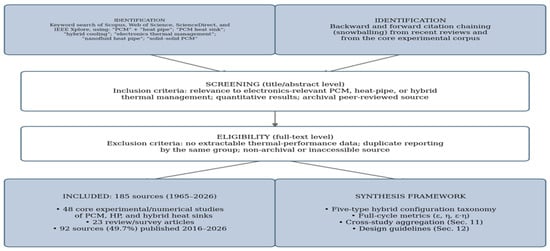
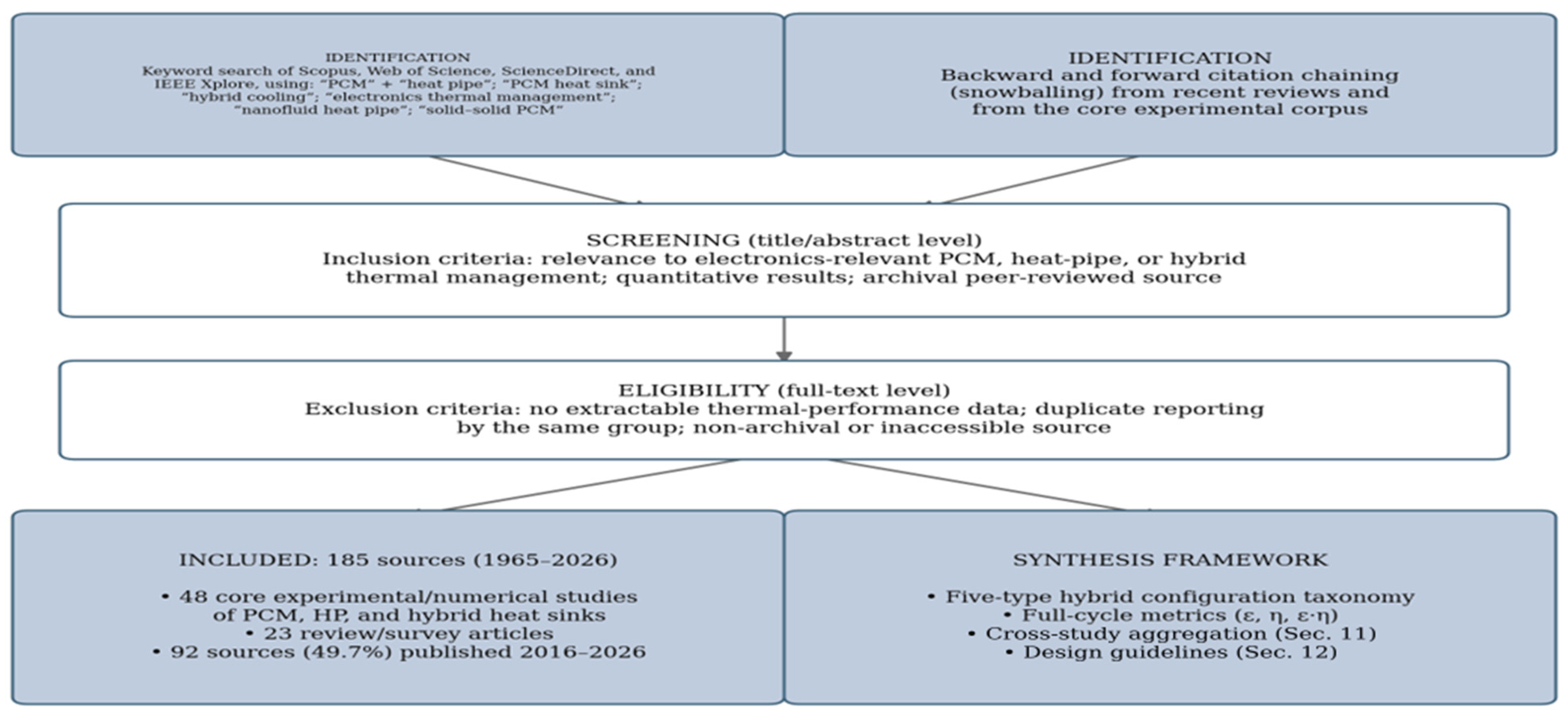
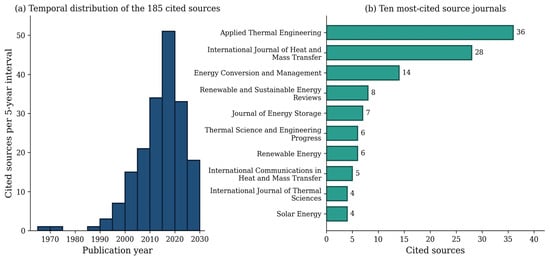
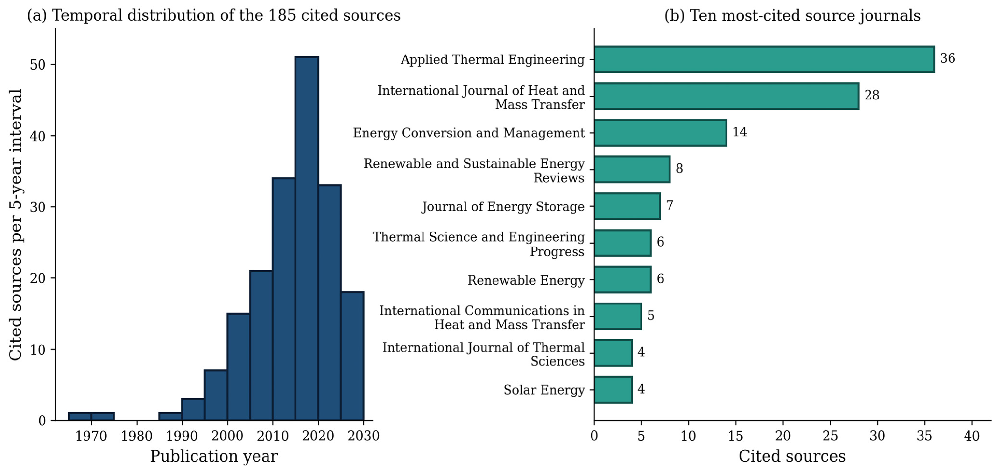
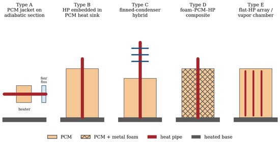
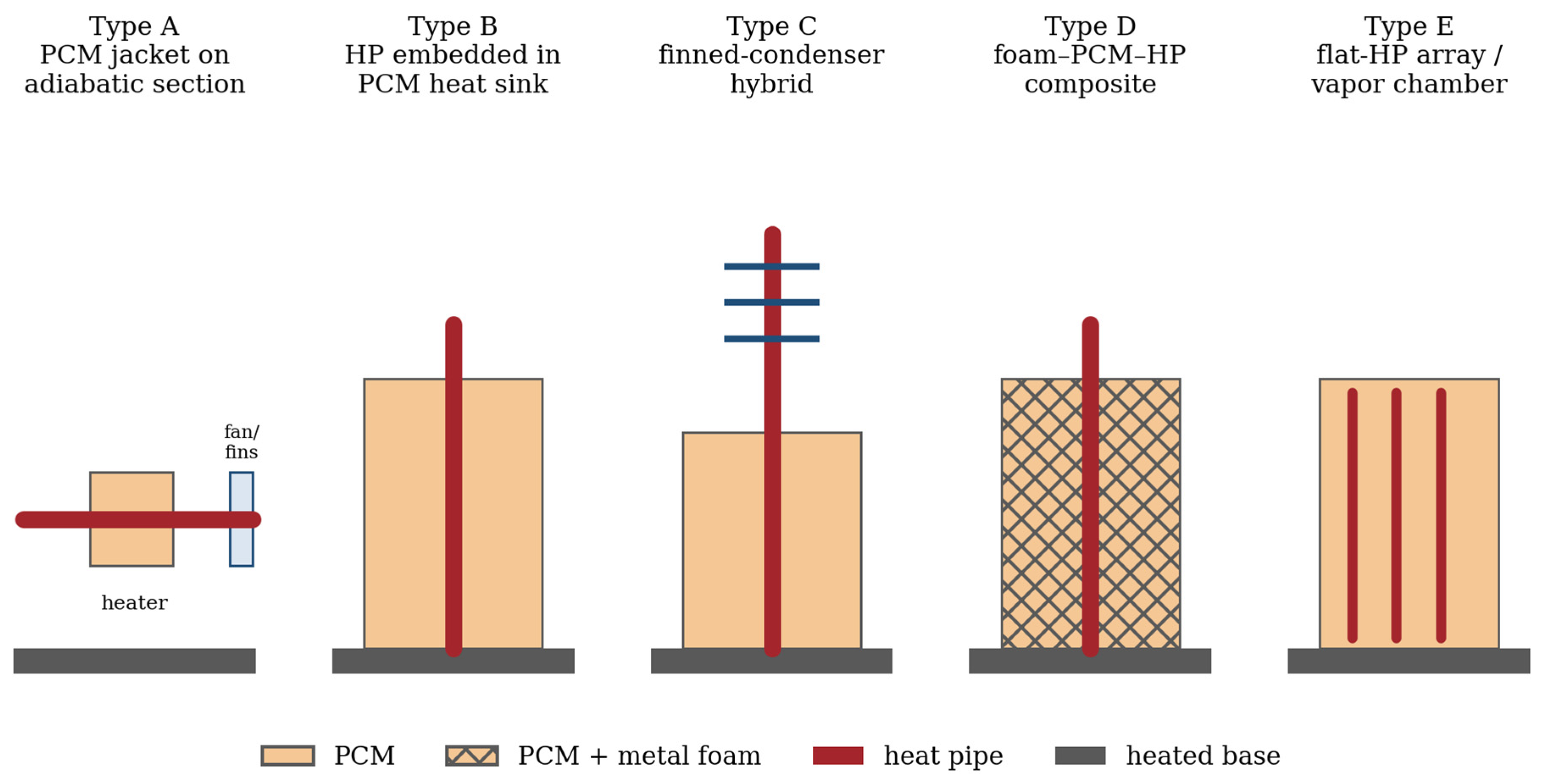
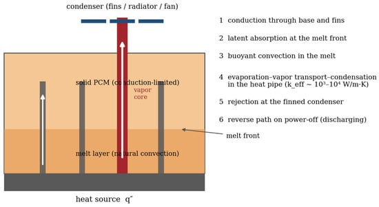
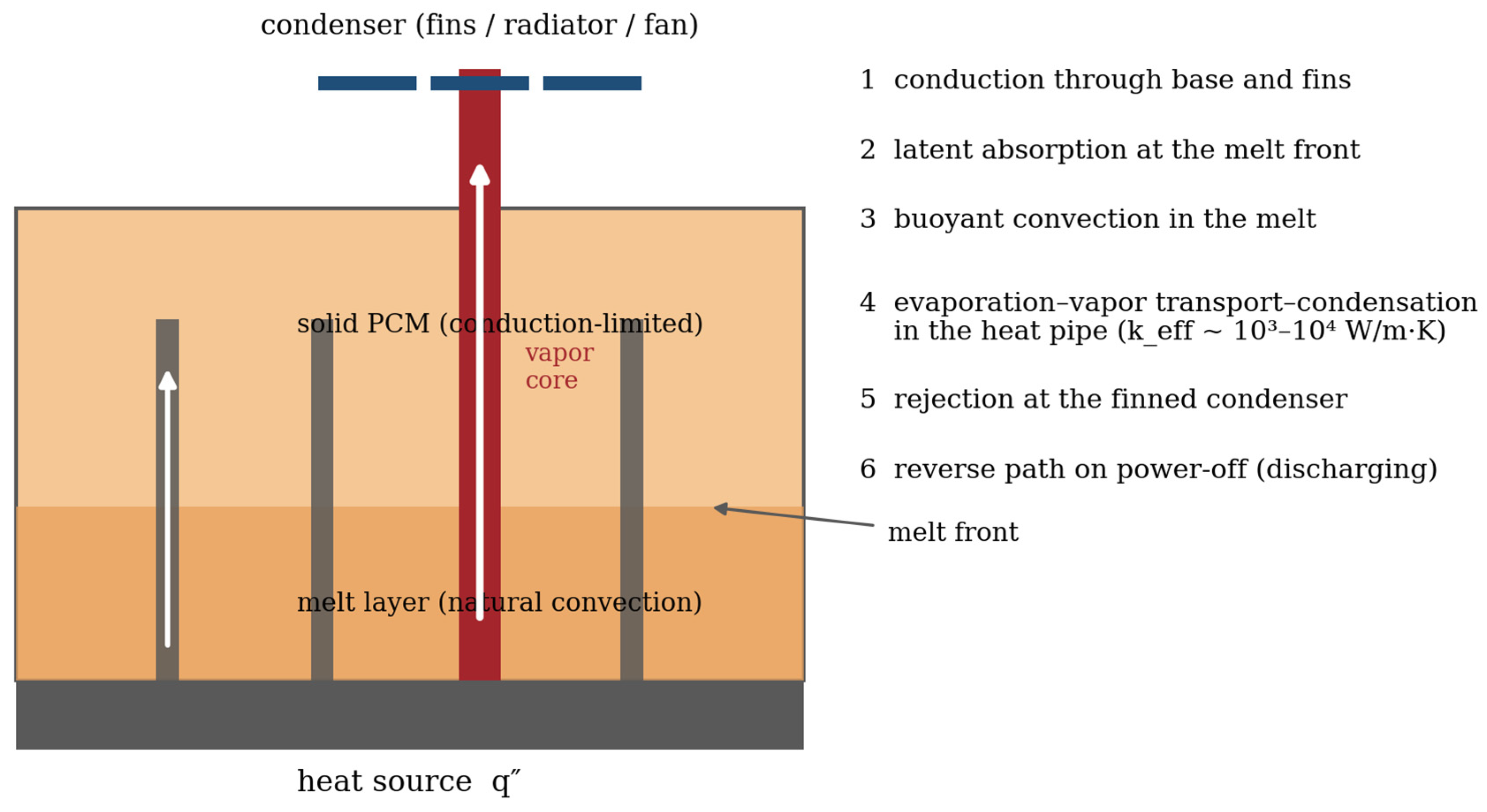
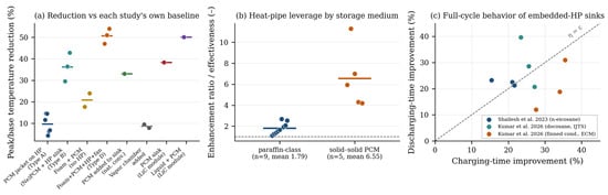
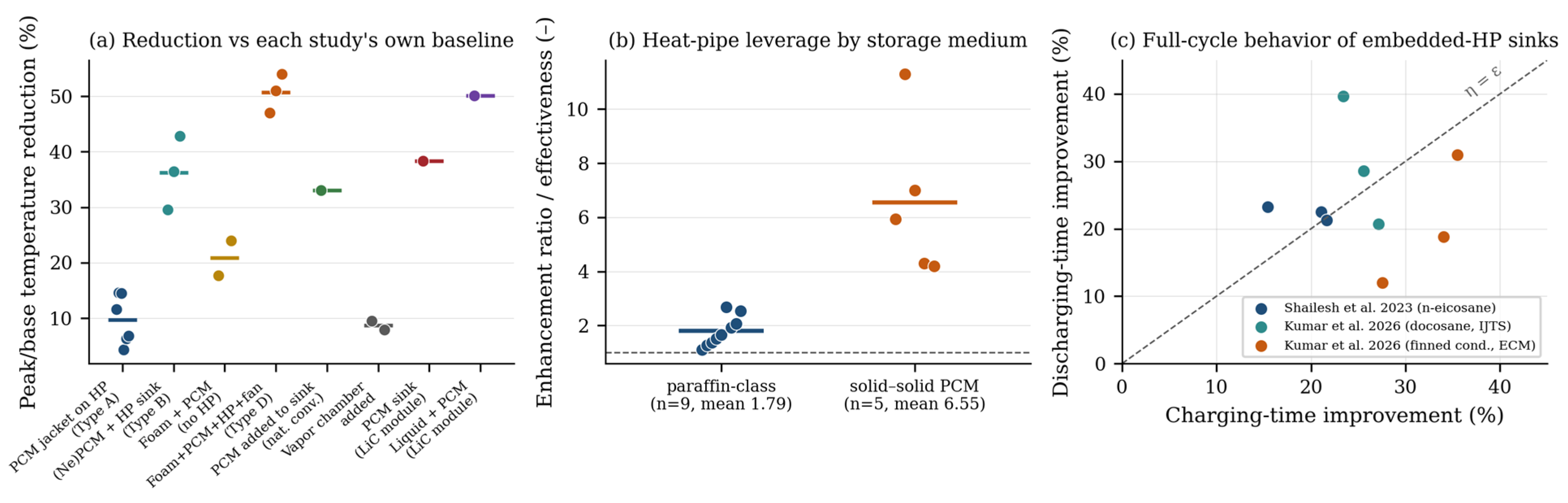
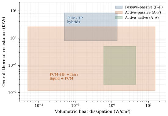
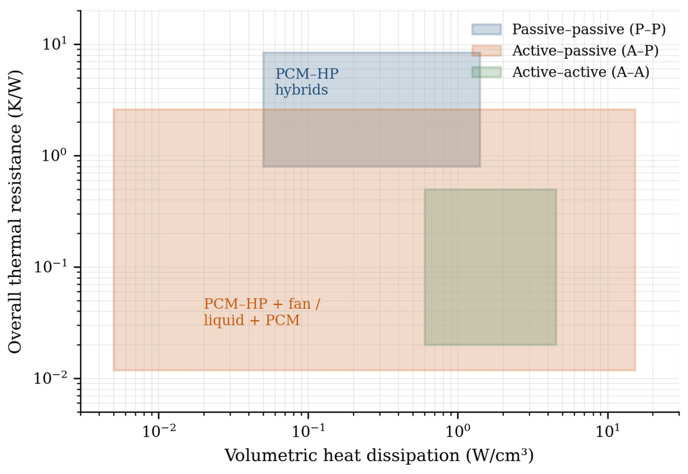
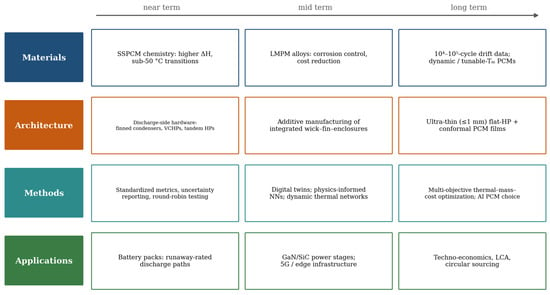
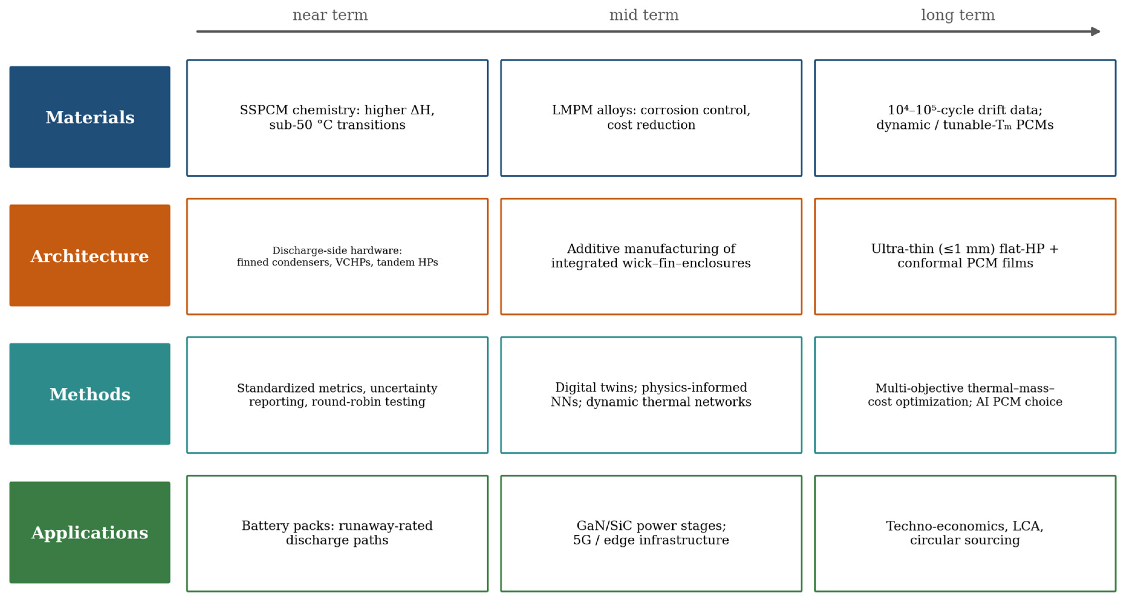
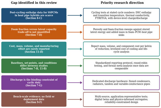
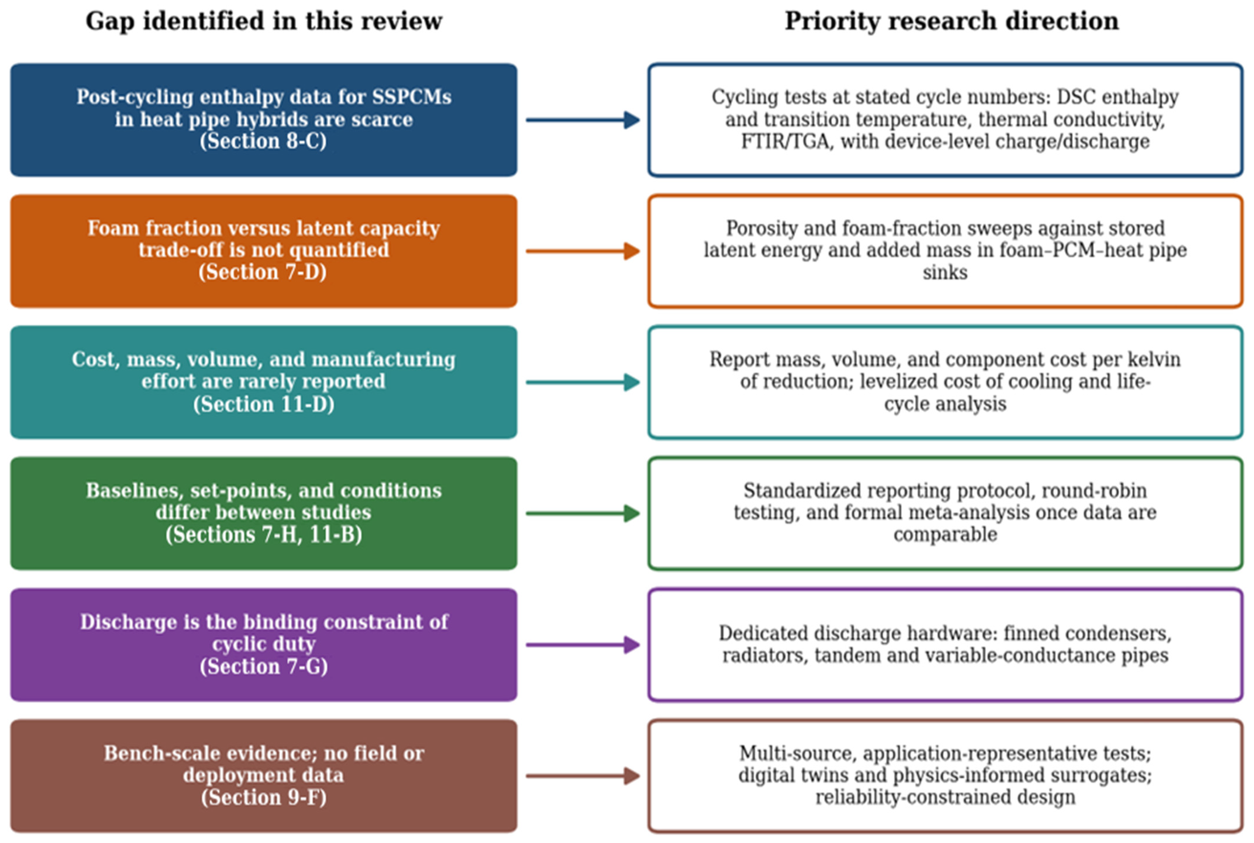

Disclaimer/Publisher’s Note: The statements, opinions and data contained in all publications are solely those of the individual author(s) and contributor(s) and not of MDPI and/or the editor(s). MDPI and/or the editor(s) disclaim responsibility for any injury to people or property resulting from any ideas, methods, instructions or products referred to in the content. |
© 2026 by the authors. Licensee MDPI, Basel, Switzerland. This article is an open access article distributed under the terms and conditions of the Creative Commons Attribution (CC BY) license.