


Abstract
Hardware-in-the-loop (HIL) simulation is an essential tool for rapid and cost-effective development and validation of power-electronic systems. The primary objective of this work is to validate and fine-tune a PLECS-based HIL model of a single dual active bridge (DAB) DC-DC converter, thereby laying the foundation for building more complex models (e.g., multiple converters connected in series or parallel). To this end, the converter is experimentally characterized, and the HIL model is validated across a wide range of operating conditions by varying the PWM phase-shift angle, voltage gain, switching frequency, and leakage inductance. Power transfer and efficiency are analyzed to quantify the influence of these parameters on converter performance. These experimental trends provide insight into the optimal modulation range and the dominant loss mechanisms of the DAB under single phase shift (SPS) control. A detailed comparison between HIL simulations and hardware measurements, based on transferred power and efficiency, shows close agreement across all the tested operating points. These results confirm the accuracy and robustness of the proposed HIL model, demonstrate the suitability of the PLECS platform for DAB development and control validation, and support its use as a scalable basis for more complex multi-converter studies, reducing design time and prototyping risk.
1. Introduction
In recent years, the introduction of renewable energy sources (RES), such as photovoltaics and fuel cells, has been actively promoted as a means of addressing environmental issues. To accelerate the use of RES, independent distribution systems, often defined as micro or nanogrids, have become a solution for overcoming the power fluctuations of RES. Among them, the DC microgrid is gaining rapid attention from researchers as an auxiliary solution to the existing power network, as it facilitates the integration of battery energy storage systems (BESS) and EV fleets [1,2].
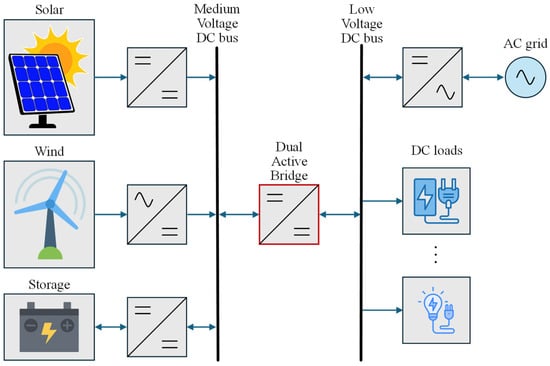
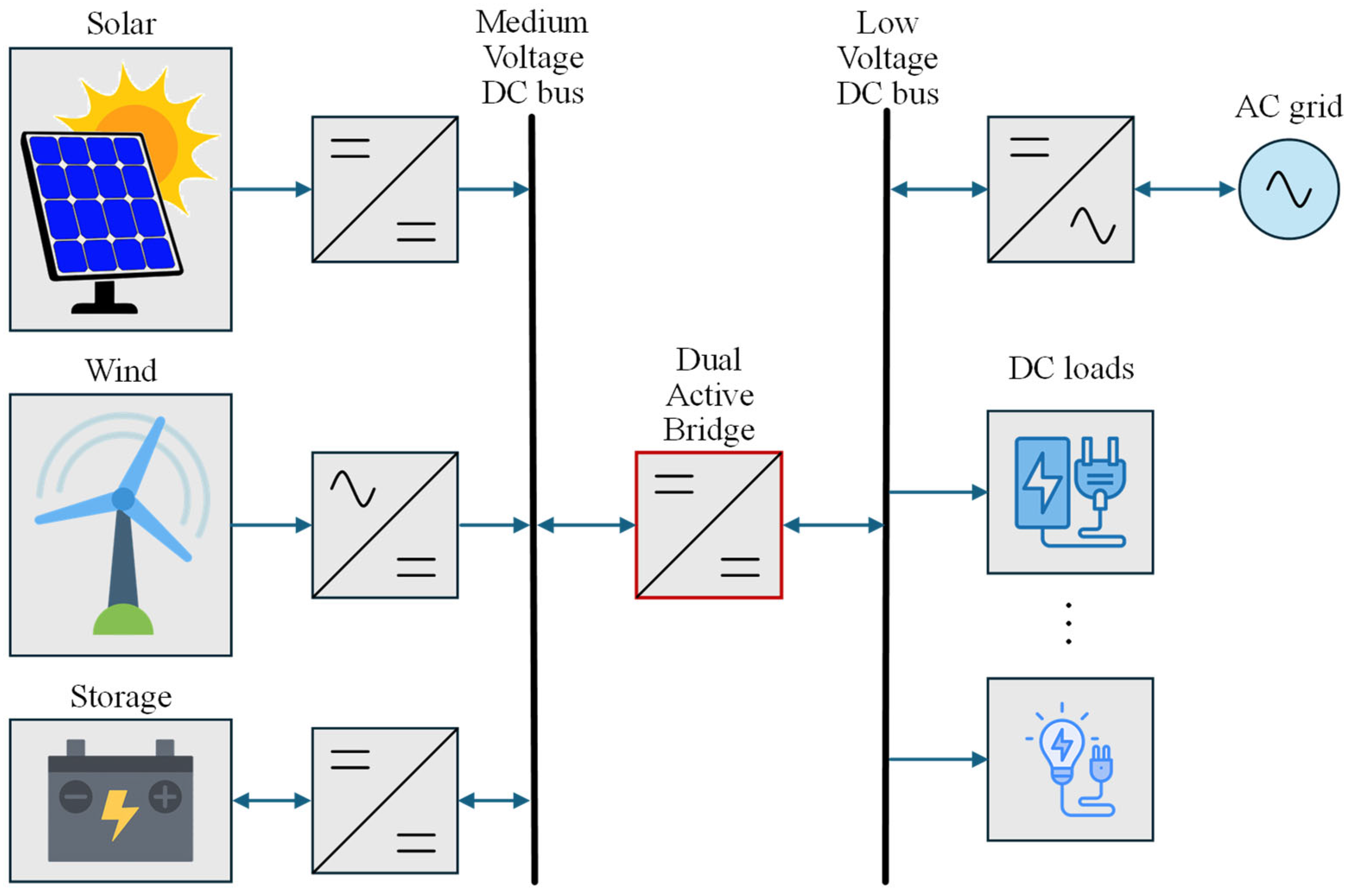
In a DC microgrid, converting power between different voltage levels requires features such as high-power density and bidirectional power flow. Additionally, when interconnecting a medium-voltage bus to a low-voltage bus, galvanic isolation becomes essential. This is to avoid the propagation of faults and improve grid safety, as well as enable the possibility to maintain two different grounding schemes. The isolation can be achieved using high-frequency transformers (HFT) because of their compact size and low weight. Consequently, isolated bidirectional DC-DC converters that employ fast-switching semiconductor devices are considered the most suitable solution for interconnecting DC buses operating at different voltage levels [3]. Figure 1 presents a general block diagram of a DC microgrid, where a DC-DC converter provides the link between two DC buses to regulate power flow.
Figure 1.
Architecture of a possible DC microgrid.
Various isolated DC-DC converters have been investigated in the literature for bidirectional operation. Among them, the DAB converter appears to be an ideal solution because of its unique features, such as a wide range of operating voltages (high voltage gain), a wide zero voltage switching (ZVS) region, bidirectional power transfer, high-power density, enhanced power flow capability, and galvanic isolation. In addition, DAB contains fewer components than resonant converters and forms an integral part of a solid-state transformer or smart transformer [4].
Various control techniques have been proposed in the literature for regulating the performance of conventional DABs, each having their own advantages and limitations [5]. The modulation strategies for DAB converters are generally divided into four main types according to the control variables used or the number of available control degrees of freedom. The most straightforward strategy utilizes a single degree of freedom to control the power transfer of the DAB converter and is referred to as single phase shift (SPS) modulation [6,7] that controls the phase-shift ratio between the primary side full bridge and the secondary side full bridge. It has high efficiency at full load and a unity voltage conversion ratio due to ZVS. However, when there is a deviation in the voltage conversion ratio from unity, especially at light load, it loses ZVS and undergoes hard switching, thus leading to increased switching losses. Moreover, it also increases reactive power (circulating power) and current stress, which reduces its efficiency. To overcome these aforementioned limitations, the extended phase shift (EPS) [8,9] and dual phase shift (DPS) [10,11] techniques were proposed. For the EPS modulation scheme, the internal phase-shift duty ratio of one full bridge can also be adjusted. Similarly, by modifying the SPS control, the DPS modulation scheme can regulate the internal phase-shift duty ratios of both full bridges for the DAB converter with the same value. Both EPS and DPS modulation schemes have two control variables. The triple phase shift (TPS) modulation scheme [12,13] independently regulates the duty ratios of the two full bridges, as well as the phase shift between them, thereby providing the highest degree of control freedom while maintaining a constant switching frequency. Consequently, SPS, EPS, and DPS modulation strategies can be regarded as special cases of TPS control.
In the development of a physical prototype of a power electronic converter intended for a specific application, the initial step typically involves verifying the feasibility and fundamental technical characteristics of the proposed concept. For this purpose, various computer-based simulation tools are employed to analyze the electrical behavior of the converter. Two main approaches are commonly used to simulate the power stage and the control system. The first, which represents the conventional method, relies exclusively on offline simulation, also referred to as software-in-the-loop (SIL) simulation. The second approach uses online simulation through a HIL system [14].
In the traditional SIL-based approach, simulation tools are primarily used to model the electrical behavior of the converter’s power stage. These offline simulations are followed by component selection and the construction of a physical prototype of the power stage. Subsequently, laboratory experiments are conducted together with the control electronics. Errors identified during testing usually require modifications to both the power and control stages, leading to multiple design iterations. An increased number of iterations inevitably results in higher development costs and longer design timelines [15].
In contrast, the HIL simulation approach delays the realization of the physical converter prototype until after the control electronics have been thoroughly tested and validated. In this case, the power stage model developed through offline simulation is implemented on a real-time emulator that reproduces the dynamic behavior of the converter. The emulator is interfaced with the control hardware through analog and digital input and output channels, allowing the embedded control algorithm to be evaluated under realistic operating conditions. Particularly, for complex converter topologies or systems involving multiple interconnected power conversion stages, this approach accelerates the design process and improves both efficiency and cost effectiveness compared to methods based solely on offline simulations [16]. Nevertheless, careful validation of each stage model is essential to avoid the propagation of modeling errors or the underestimation of secondary effects.
This paper presents the key steps in designing the HIL simulation model of the DAB DC-DC converter using PLECS RT BOX 1 CE real-time power electronics emulator from Plexim, and the relative validation through an experimental prototype. This validation is focused on behavioral accuracy rather than detailed electrical-level modeling, ensuring that the HIL approach reliably reproduces the converter’s power-transfer characteristics for system-level analysis and rapid prototyping.
Over the years, the theory behind DAB converters and HIL simulations has been well established through a number of studies, yet one crucial area still needs to be addressed by researchers, and that is the full experimental validation of HIL models in situations where the converter is operating in a multi-variable design space. Most of the findings of previous studies are limited by the operational points of the models, which are usually nominal points, and the variations in phase shift and power transfer are mainly considered [17,18,19,20]. Furthermore, in [21], a real-time high-fidelity model for DAB converter systems has been investigated using OPAL-RT, addressing HIL simulation challenges like simulation time step, switching signal oversampling, and mode states calculation. Moreover, in [22], control hardware-in-the-loop based on Typhoon Platform is used to validate a new control strategy based on a double integral super twisting sliding mode control. In [16], an FPGA-based HIL real-time simulator is used to test control designs of DAB-based battery-charging systems, and the HIL results are eventually compared with offline modeling results. The comparison shows that HIL provides satisfactory performance in terms of accuracy and latency. In addition, the authors of [23] use dSpace and PLECS RT-Box HIL platforms to validate in real-time a moving discretized control set model and predictive control strategy for DAB converter output voltage regulation. Even though the controller seems to have good performance, no comparison has been made with offline models.
In all the previously mentioned works, a detailed experimental study, which at the same time investigates the impact of different parameters on power transfer and efficiency, is completely missing. This includes parameters like phase shift, voltage gain, switching frequency, inductance, and PWM duty ratio, which are central to DAB optimization. This is necessary for the precise validation of HIL models and the understanding of converter behavior in the real world. The present paper fills this gap by carrying out a very thorough, multi-faceted experimental characterization and validation of a PLECS-based HIL model of the DAB converter, systematically evaluating converter performance across a wide matrix of operating conditions, thus providing valuable insight into its steady-state and efficiency characteristics.
The rest of this paper is structured as follows: Section 2 presents the operational principle of a DAB converter, while Section 3 addresses the basics of DAB HIL setup in PLECS. Furthermore, Section 4 shows the experimental testbench and different characterizations performed on the DAB converter. The multi-variable comparative results derived from both the HIL setup and experiments are also presented in this section, and the work is concluded in Section 5.
2. Operating Principle of DAB Converter Under SPS Modulation
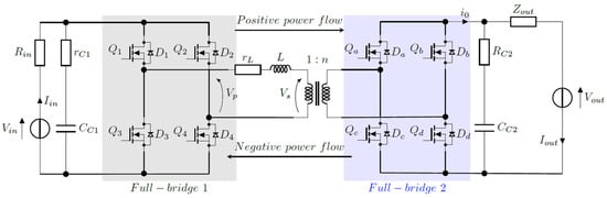
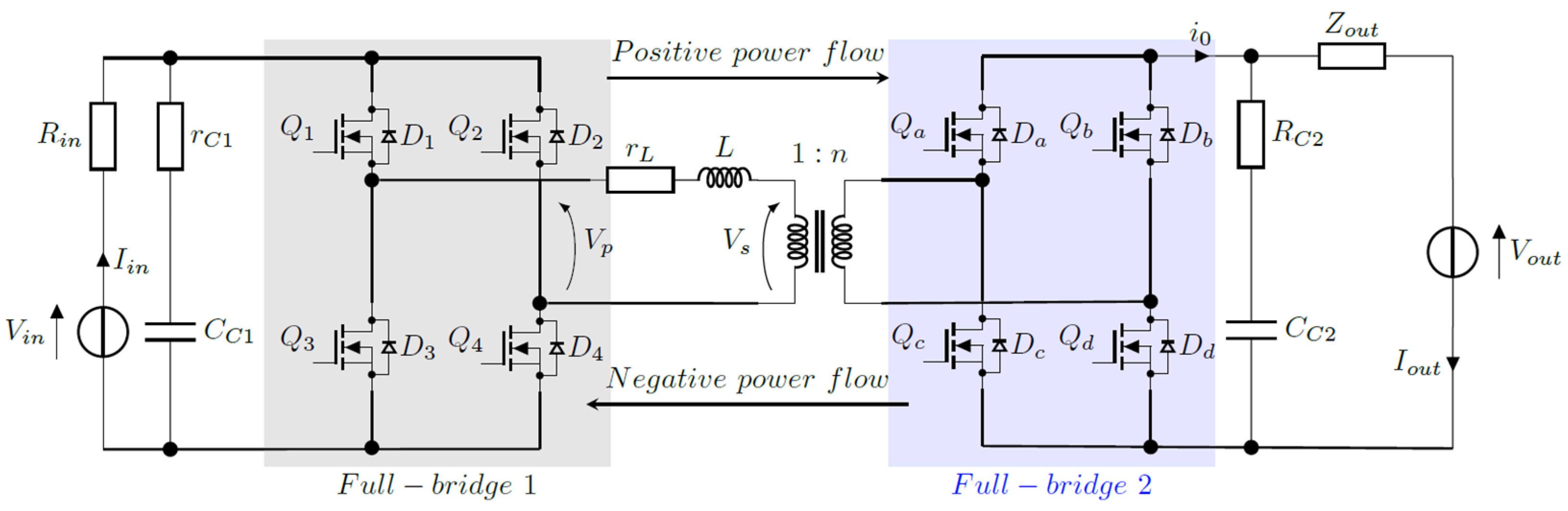
The simplicity of SPS modulation makes it the most commonly employed method for controlling power flow in DAB converters. The basic DAB converter topology is illustrated in Figure 2. It consists of two full-bridge converters, an isolation HFT, and an energy storage inductor, which may be either an external inductor or the lumped leakage inductor of the transformer.
Figure 2.
Basic architecture of a DAB converter.
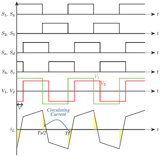
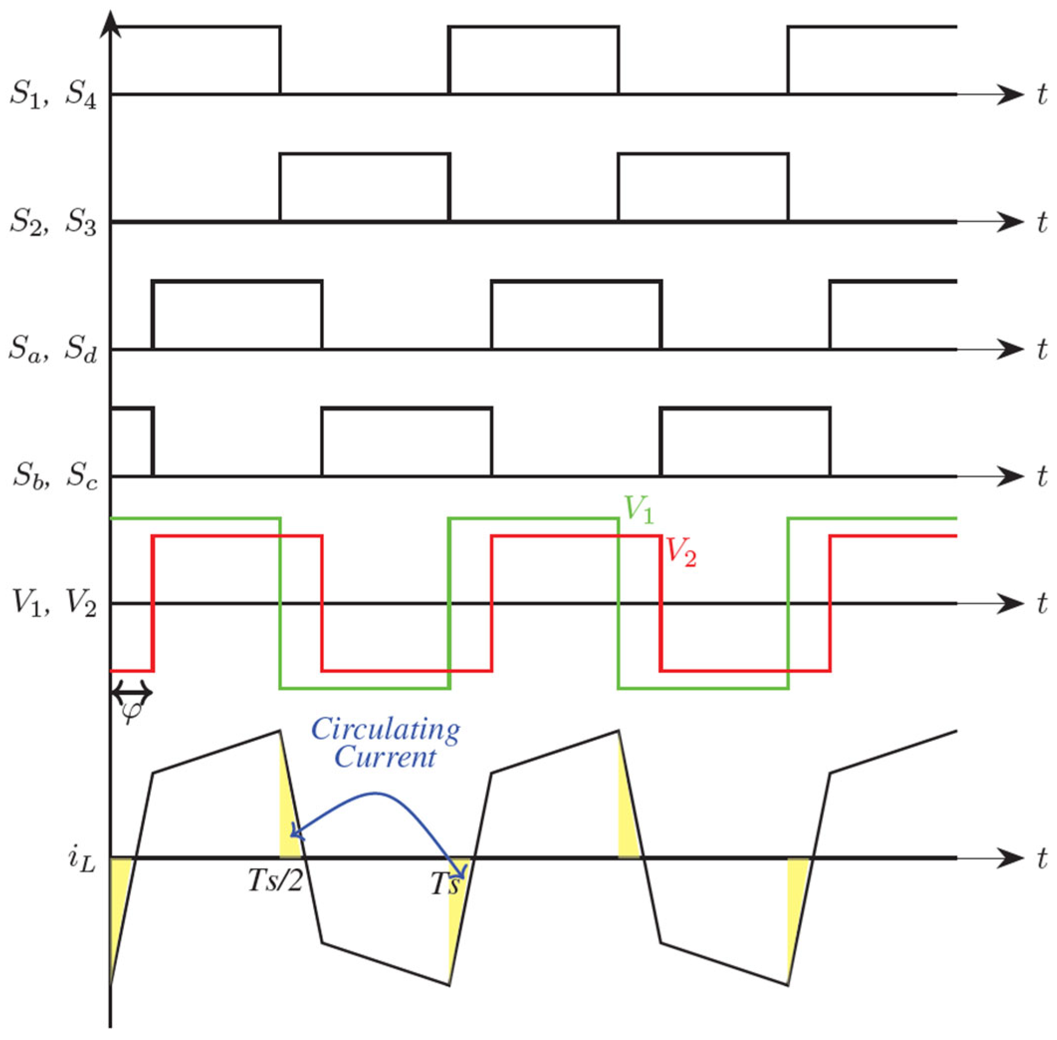
As illustrated in Figure 2, the converter’s two H-bridges convert the DC input and output voltages into high-frequency, two-level square waves (V1 and V2). Power flow is controlled by adjusting the phase shift between these square waves using SPS modulation. The figure also indicates the possible directions of power flow, which depend on the sign of the phase shift angle. A positive angle corresponds to V2 lagging behind V1, resulting in positive power flow while a negative angle corresponds to V1 lagging behind V2, producing negative power flow. Figure 3 presents typical steady-state waveforms of a DAB converter operating in buck mode (Vin > Vout) with positive power flow under SPS modulation. In this mode, both bridges switch at the same frequency with a 50% duty cycle [24,25,26].
Figure 3.
Typical theoretical waveforms of the DAB converter under SPS modulation.
By ignoring the resistive losses in the converter, the average transmitted power can be expressed by (1), where fsw is the switching frequency of the converter, 1:n is the transformer turns ratio of the HFT, and L is the equivalent inductance given by (2). In (2), Ltr1 and Ltr2 are, respectively, the leakage inductances of the primary and secondary sides of the HFT, while Ls is the additional series inductance.
According to (1), the magnitude of the power transferred in the positive direction increases as the phase shift angle (φ) increases to a maximum of π/2, after which any increase in phase shift angle causes a decrease in power sent. A similar pattern is found in the reverse direction, with the highest reverse power obtained at −π/2.
3. Hardware-in-the-Loop Modeling of DAB Converter Using PLECS
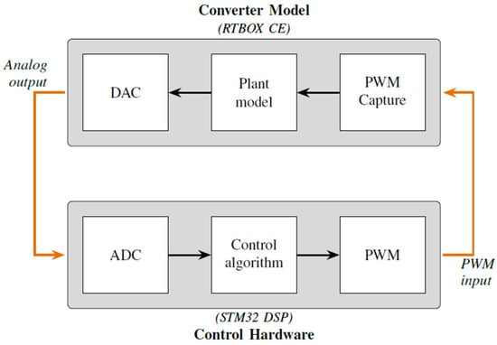
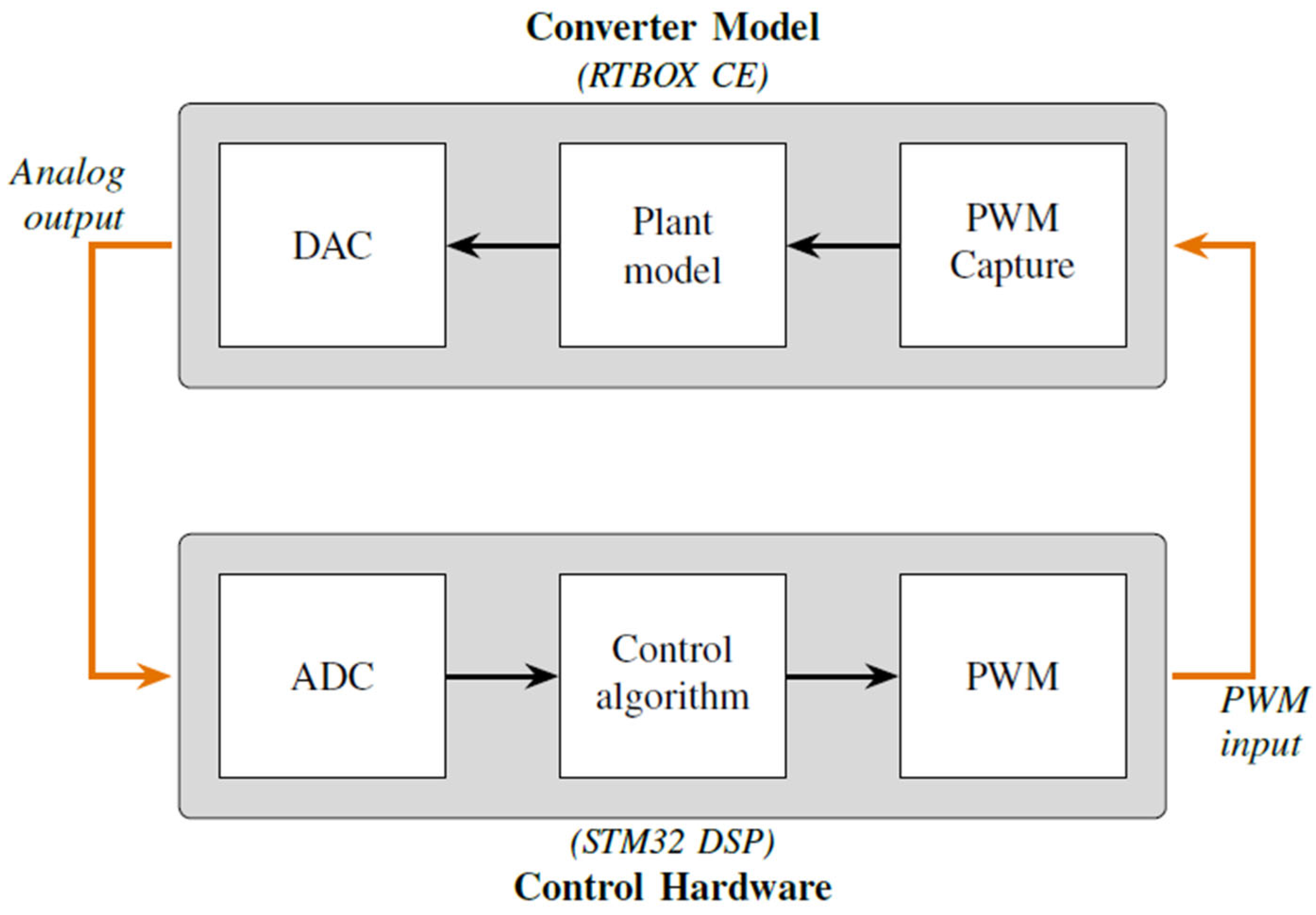
In HIL testing, the DAB power converter with its load serves as the physical device under test (DUT) and represents the plant. The plant model is implemented on the RT BOX 1 CE power electronics emulator from Plexim (Zurich, Switzerland) using the PLECS 4.4.1 circuit simulator environment. The control algorithm runs on an STM32F446RE microcontroller development board (STMicroelectronics, Geneva, Switzerland). Physical connectivity between the RT BOX CE and the STM32 microcontroller is provided by interface boards, which enable the real-time emulation of the DAB power stage while protecting and routing the input-output pins between the emulator and the microcontroller. Figure 4 shows the block diagram of HIL testing.
Figure 4.
Block diagram of HIL Testing.
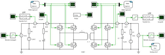
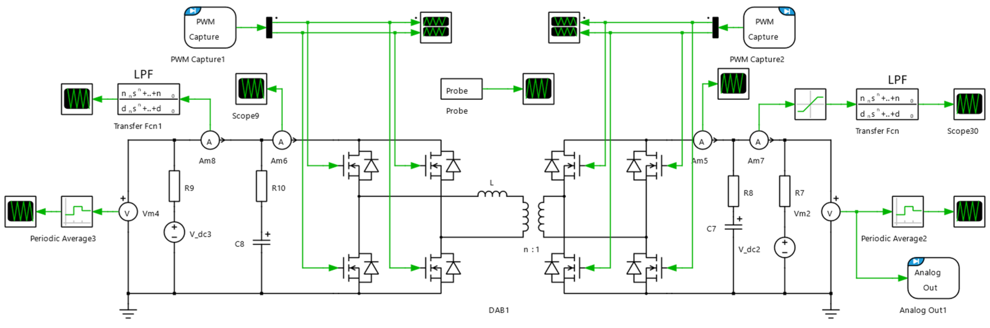
During the development of the HIL simulation model, it is essential to account for both the physical limitations of the RT BOX CE hardware and the need to optimize simulation accuracy. A key optimization step involves using either sub-cycle averaging or nanostep models for the switching devices, combined with the PWM Capture components implemented on the RT BOX CE FPGA. This real-time optimization allows for smaller simulation time steps and enables the simulation of converters operating at much higher switching frequencies. Additionally, by selecting an appropriate discretization time step, the PLECS hybrid power modules can accurately reproduce the main switching ripple characteristics while reducing the number of ideal switches and diodes in the model. This, in turn, decreases the number of state-space matrices required to describe the converter and lowers the computational load of real-time simulations. The plant model of the DAB HIL setup in the PLECS environment is shown in Figure 5.
Figure 5.
Plant model of the HIL testing in PLECS.
The DAB HIL model implemented in Figure 5 is switched at a frequency of 100 kHz, has a series inductance of 10 µH, and a transformer turns ratio of 1:1. Open loop power flow characterization of the converter is performed by using the STM32 microcontroller which generates the required complementary PWM signals for each real-time phase shift imposed in the software. In the microcontroller, Timer 1 acts as the primary timer and is used to generate PWM for the primary full bridge, while Timer 8, triggered by Timer 1’s output compare register (OC2REF), acts as the secondary timer in reset mode, and is used to generate complementary PWM for the secondary full bridge. A dead-time of 10 ns is set in each timer module to ensure there is no shoot-through between the high-side and low-side switches of each half-bridge leg. Externally, the PWM output pins of the DSP are connected to the Digital input pins of the PLECS RT-BOX found on the digital breakout board. In the PLECS environment, the PWM capture module is used to read these PWM signals, which are then fed to the respective legs of the DAB converter. The converter is characterized at equal input and output voltages of 10, 20, and 30 V, as well as under the condition where the input voltage is 30 V, and the output voltage is 42 V. The IL results obtained are provided in Section 4, where they are compared with the experimental results. The main limitations of the HIL setup include the RT Box CE’s finite computational capacity, which ensures that a time step of less than 1 µs cannot be used, thus also placing a limit on the maximum switching frequency. Also, some parasitic elements have not been modeled in the HIL setup, and this may slightly impact the accuracy of the transient responses. Furthermore, the interface boards introduce a finite signal propagation delay of approximately 1 µs due to analog signal conditioning, ADC/DAC conversion, and internal buffering. While this latency is negligible for steady-state operation and low-frequency control dynamics, it becomes more relevant at high switching frequencies and during fast transient events.
4. Experimental Setup, Characterization, and Results
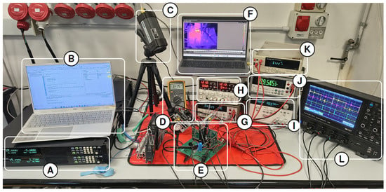
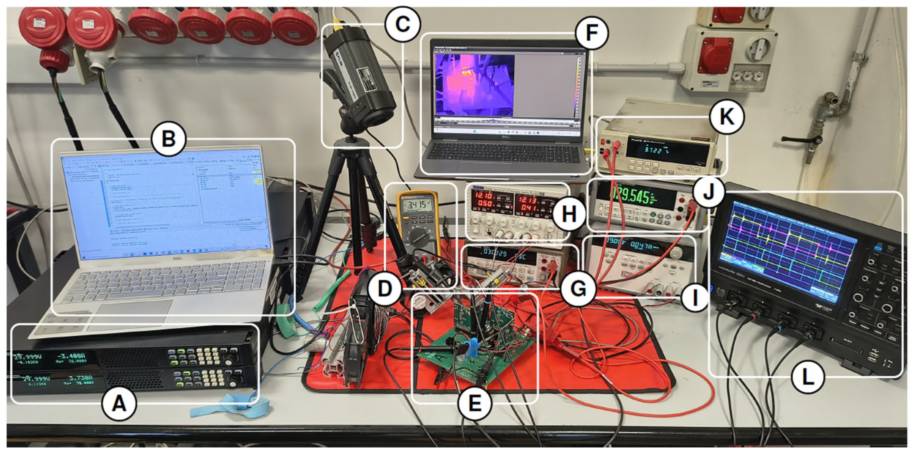
An experimental prototype of the DAB converter was assembled as shown in Figure 6. The converter used a motherboard that hosts four half-bridges implemented with wide-bandgap GaN power transistors from EPC (EPC23102). GaN devices were selected to enable higher switching frequencies while keeping dynamic switching losses low, which was particularly advantageous for the low DC-link voltages targeted in this work (≤50 V). The choice of 100 kHz was made as a practical compromise as it was high enough to ensure good transformer performance and manageable passive component sizing, but not so high as to complicate the future interconnection of multiple converters in modular architectures. GaN technology was preferred over SiC because it enables excellent performance at low voltages, offers fast transients without requiring complex thermal management, and overall supports rapid prototyping.
Figure 6.
Picture of the DAB experimental test bench for carrying out tests. From left to right: (A) Bidirectional power supply ITECH IT-M3902C-85-40SAS, (B) PC for microcontroller monitoring, (C) Thermal IR camera FLIR A325, (D) Multimeter FLUKE 83V, (E) DAB prototype, (F) PC for thermal imaging monitoring, (G) Multimeter HP 34401A, (H) Power supply TTI CPX400DP, (I) Power supply Keysight E3646A, (J) Multimeter Keysight 34450A, (K) Multimeter FLUKE 45, and (L) Oscilloscope Teledyne LeCroy WaveSurfer 3024z.
For the isolation stage, an off-the-shelf planar HFT was chosen: Coilcraft PL300-100L (Cary, IL, USA). This type of transformer provides a highly uniform turns ratio over a wide frequency range, exhibits low leakage inductance and low parasitic resistance, and is designed to operate at nominal 48 V voltage and switching frequencies in the hundreds of kilohertz. Its compact planar structure also minimizes winding capacitance and improves thermal dissipation, making it suitable for high-density designs and early-stage prototyping.
Two ITECH IT-M3902C-85-40SAS bidirectional power supplies were used to set the input and output voltages of the DAB converter. The experimental setup also includes an oscilloscope (Teledyne LeCroy WaveSurfer 3024z) for monitoring PWM switching waveforms, currents, and voltages, as well as auxiliary fans for active cooling. A FLIR A325 thermal imaging camera was employed to detect any potential overheating during the tests. Particular attention was given to the GaN power transistors, inductors, and transformers, as these are the components most subject to heat dissipation. Table 1 shows the converter specifications adopted for the initial tests. The converter control and characterization were performed using an STM32F446RE development board.
Table 1.
Specifications of the DAB converter in the early test.
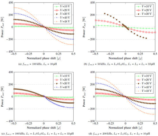
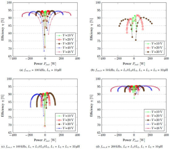
Given the scope and objective of the study, namely, to validate the PLECS-based HIL model of a single DAB converter under DC characteristics, the modulation technique does not play a significant role, and therefore the standard SPS modulation has been chosen. The results of the power transfer and efficiency obtained for different series inductors’ inductances (L), voltages, and switching frequencies (fsw) when the converter normalized gain is M = Vout/(n × Vin) = 1 (i.e., in this case, Vout = Vin) are shown in Figure 7 and Figure 8. As outlined in Figure 7, four different configurations were tested: (a) a single 10 µH inductor at 100 kHz; (b) a parallel combination of three 33 µH inductors (resulting in an effective inductance value of 11 µH) at 50 kHz; (c) the same 11 µH parallel inductor bank at 100 kHz; and (d) a parallel combination of two 10 µH inductors (resulting in 5 µH) at 200 kHz. These variations allow for the analysis of the impact of the characteristic impedance Z = jωL (where ω = 2πfsw, and ) on power transfer, soft-switching, and overall efficiency.
Figure 7.
Power transfer characterization at different voltages, frequencies, and inductances, V = n × Vin = Vout.
Figure 8.
Efficiency characterization at different voltages, frequencies, and inductance values, V = Vin = Vout.
The results outlined in Figure 7 show that for any given phase shift, the magnitude of the power transfer increases proportionally as the voltages increase from 10 V to 48 V, confirming the direct relationship between power flow and voltage amplitude according to Equation (1). Moreover, the power curves across all voltages increase as the phase shift increases, with a peak in power occurring when the normalized phase shift is 0.5. It is also noticeable that the power transfer curves shown in Figure 7a,d are nearly identical despite the different inductances and switching frequencies. This is because both configurations have the same characteristic impedance (i.e., their reactances are Xa = ωaLa = 2π × 100 × 103 × 10 × 10–6 = 2π Ω and Xd = ωdLd = 2π × 200 × 103 × 5 × 10–6 = 2π Ω). If we compare all four plots at 20 V, it is observed that Figure 7b provides the largest power transfer simply because its characteristic impedance is the smallest, i.e., Xb = ωbLb = 2π × 50 × 103 × 11 × 10–6 = 2π × 0.55 Ω.
The efficiency curves in Figure 8 show that, at a particular voltage, efficiency increases as the power demand increases up to an optimal point, after which efficiency drops. As we move from one voltage level to the other, the zone of higher efficiency changes. In all cases, the light load efficiency is highest when the voltage is smallest due to lower switching losses, while the heavy load efficiency is highest when the voltage is largest. The efficiency curves in Figure 8d are higher than those of Figure 8a, mainly because the DC resistance of the inductor is lower (1 mΩ//1 mΩ = 0.5 mΩ), hence the conduction losses are reduced.
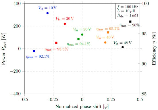
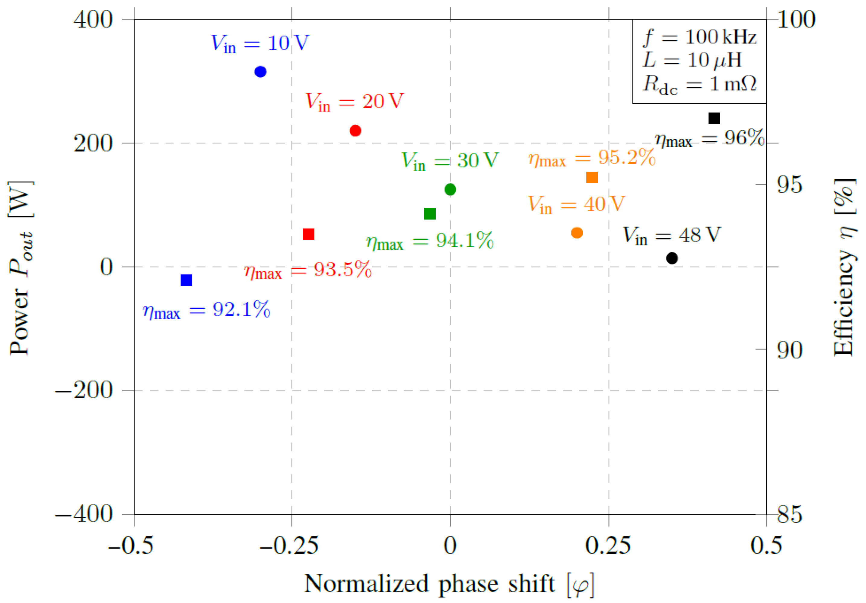
An extraction of the maximum power and efficiency points at different voltages for the case given in Figure 7a and Figure 8a provide the plot shown in Figure 9, where it is clearly seen that as the input/output voltage increases, the maximum efficiency increases up to a maximum of 96% when the voltage is 48 V.
Figure 9.
Power points and maximum efficiency for different bus voltages (fsw = 100 kHz, L = 10 μH).
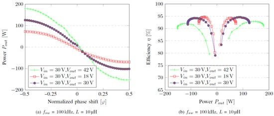
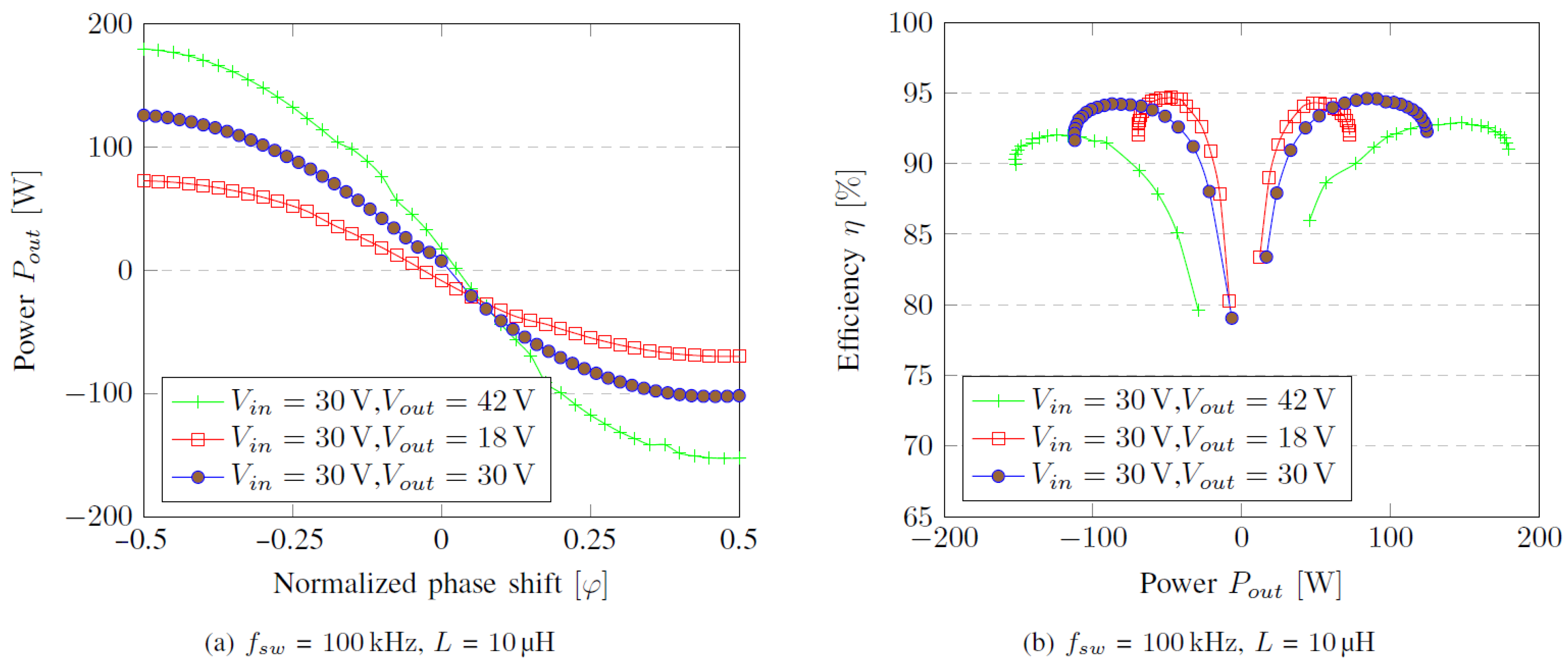
Figure 10 shows the DAB power transfer and efficiency curves when the DAB converter is characterized at different gain values of M = 0.6 (Vin = 30 V, Vout = 18 V), M = 1 (Vin = 30 V, Vout = 30 V), and M = 1.4 (Vin = 30 V, Vout = 42 V). It is observed in Figure 10a that as the gain increases, more power can be transferred for every increase in the phase shift. Moreover, Figure 10b shows that the efficiency of the converter at light load is higher when the converter gain is lowest (M = 0.6), whereas the efficiency at heavy load is highest when the converter gain is highest, and finally, at medium loads, the efficiency is highest when M = 1.
Figure 10.
Characterization of the different converter gains at M = 0.6, 1, and 1.4.
The efficiency trends in Figure 10b can be explained by the distribution of conduction and switching losses at different operating points. Operating at light load with a lower gain (M = 0.6) minimizes circulating current and core excitation, leading to reduced conduction and magnetizing losses, and, therefore, higher efficiency. However, a higher gain (M = 1.4) reduces the required phase shift to deliver the same power at a heavy load, which lowers RMS currents and conduction losses, improving efficiency. At medium loads, the system operates closest to its nominal design point when M = 1, balancing both conduction and switching losses and resulting in the highest efficiency at that gain level.
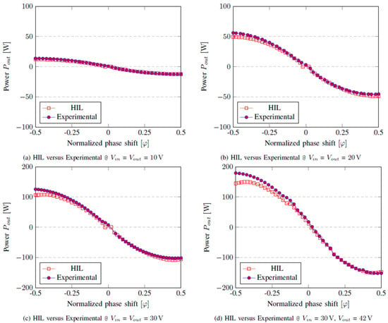
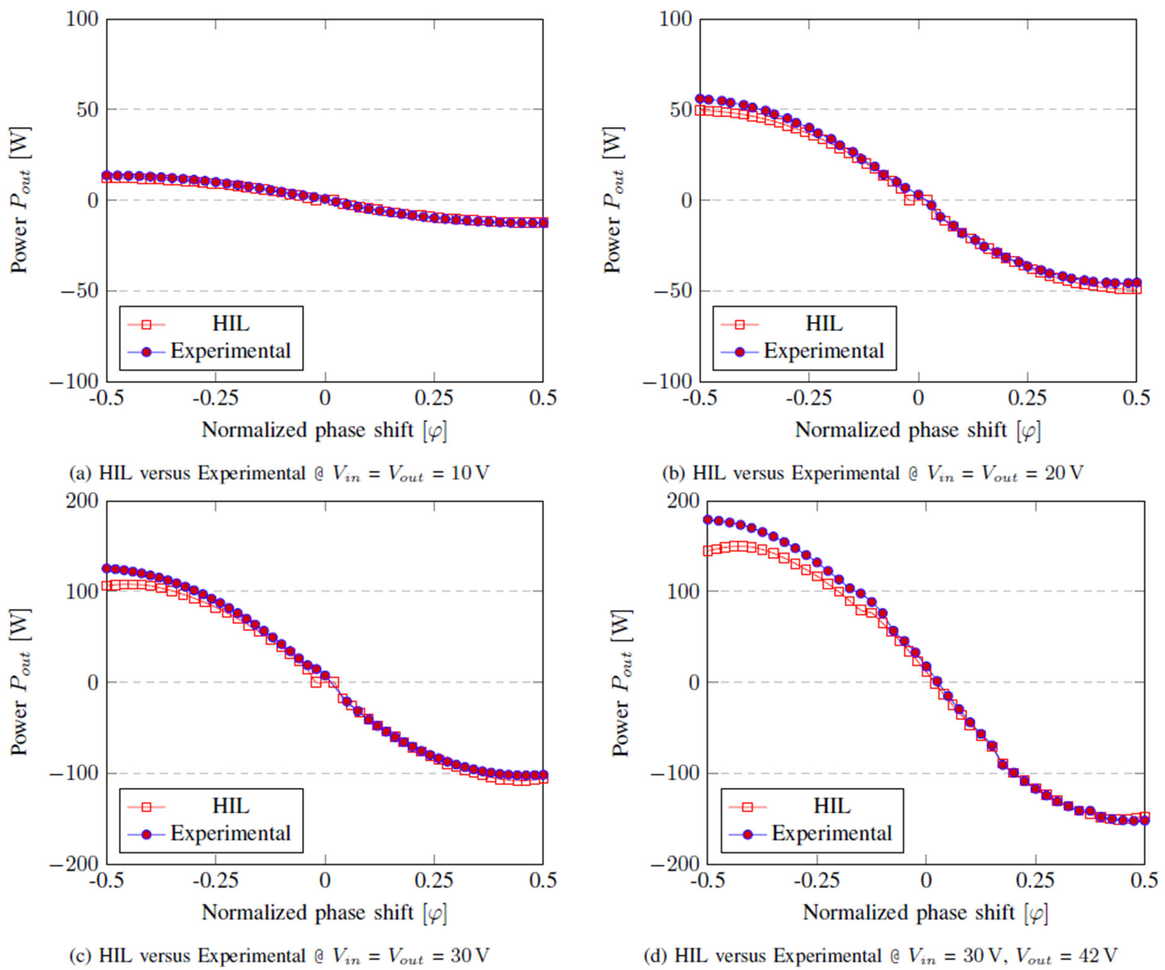
Figure 11 shows a power flow comparison of the HIL setup, with the experimental setup under different operating conditions.
Figure 11.
HIL and experimental results, with L = 10 µH, fsw = 100 kHz, and different input and output voltages.
It can be observed that in all operating conditions tested, the HIL model accurately reproduced the power-flow behavior of the converter for positive phase-shift values. In this region, the HIL and experimental curves exhibited nearly parallel trends, with power scaling consistently with the applied voltage, and both traces closely following the same power envelope as a function of phase shift. For negative phase shifts, the HIL model remained accurate at low-power levels. However, as the transferred power increased, a modest deviation emerged between the HIL predictions and the measured responses, with the greatest difference being when M = 1.4. This discrepancy can be attributed to the non-idealities of the real prototype not modeled in the HIL model, such as transformer parasitics, dead-time effects, magnetizing inductance, and switching non-linearities, which become increasingly significant at high-power levels. Overall, the proposed HIL model provided a robust and reliable representation of the physical system and is therefore suitable for further control development and testing.
5. Conclusions
This paper presented a validated, high-fidelity PLECS-based HIL simulation methodology for the development and validation of DAB converters controlled with SPS modulation. The experimental campaign spanned a wide input-voltage range (10–48 V) and investigated three voltage-gain settings (M = 0.6, 1.0, and 1.4), multiple switching frequencies, and several leakage-inductance values to enable a comprehensive parametric characterization of the converter across different operating conditions. This extensive testing ensured that the HIL model was robust, not only at nominal operating points, but also under extended scenarios, accurately reproducing the measured power-transfer trends in both nominal and off-nominal conditions. The close agreement between HIL simulations and experimental measurements validated the proposed approach for rapid prototyping and control validation. A modest divergence at the higher converter gains highlighted the limitations of idealized device models and switching approximations, and points to clear opportunities for improvement by incorporating more detailed device characterization (for example, non-ideal switch transitions, device parasitics, and thermal effects) and communication/timing jitter into the HIL model. Nevertheless, the level of agreement achieved over the investigated voltage and gain range is sufficient to fulfill the primary objective of this work, namely the behavioral validation and fine-tuning of a PLECS-based HIL model of a single DAB converter. This validated single-converter model is intended to serve as a modular building block for future multi-converter systems (e.g., series- or parallel-connected DABs), in which the overall voltage gain is typically realized through the combination of multiple stages, rather than by operating a single module at extreme gain values. Accordingly, the selected operating range provided a representative and appropriate basis for HIL validation at this stage of development, while maintaining a level of complexity compatible with early-stage model verification and control testing.
The comprehensive dataset generated during this investigation confirms that PLECS RT Box platforms, when properly interfaced with real-time DSP controllers like STM32F4466RE, can reliably emulate the DAB’s dynamic behavior in real-time, thus providing a reliable, cost-effective, and lower risk alternative to hardware prototyping for DAB converter design and optimization.
Overall, this work established a validated foundation for future research, such as advanced modulation strategies, multi-port DAB architectures, and real-time fault or stress analysis within high-power conversion systems, and demonstrated that the methodologies and validation approaches presented are transferable to other power-conversion topologies. Consequently, the proposed HIL workflow can help designers shorten development cycles and reduce prototyping risk in modern power-electronics systems.
Author Contributions
Conceptualization, A.A.N. and D.S.; methodology, A.A.N. and D.S.; software, A.A.N.; validation, A.A.N. and D.S.; formal analysis, A.A.N.; investigation, A.A.N. and D.S.; resources, D.S.; data curation, A.A.N.; writing—original draft preparation, A.A.N.; writing—review and editing, D.S., N.D. and P.C.; visualization, D.S.; supervision, N.D.; project administration, P.C.; funding acquisition, P.C. All authors have read and agreed to the published version of the manuscript.
Funding
This research was funded by the “European Union—Next Generation EU, Mission 4, Component 2, Investment 1.5, National Recovery and Resilience Plan (NRRP), CUP D93C22000460001, Project title: Ecosystem for Sustainable Transition in Emilia-Romagna”.
Data Availability Statement
The original contributions presented in this study are included in the article. Further inquiries can be directed to the corresponding author.
Acknowledgments
The authors acknowledge the use of Microsoft 365 Copilot (GPT-5 model) during the preparation of this manuscript for assistance in refining text. The authors have reviewed and edited all AI-generated content and take full responsibility for the final version of the publication.
Conflicts of Interest
The authors declare no conflicts of interest.
Abbreviations
The following abbreviations are used in this manuscript:
| DAB | dual active bridge |
| HIL | hardware-in-the-loop |
| SPS | single phase shift |
| EPS | extended phase shift |
| DPS | dual phase shift |
| TPS | triple phase shift |
| PWM | pulse width modulation |
| RES | renewable energy sources |
| BESS | battery energy storage systems |
| EV | electric vehicle |
| HFT | high frequency transformer |
| SIL | software-in-the-loop |
| DUT | device under test |
| RT BOX | real-time box (Plexim hardware) |
| GaN | Gallium Nitride |
References
- Eto, Y.; Noge, Y.; Shoyama, M.; Babasaki, T. Stability Analysis of Bidirectional Dual Active Bridge Converter with Input and Output LC Filters Applying Power-Feedback Control. IEEE Trans. Power Electron. 2023, 38, 3127–3139. [Google Scholar] [CrossRef] [Scilit]
- Ghosh, S.; Das, D.; Singh, B.; Janardhanan, S.; Mishra, S. Frequency-Domain Modeling of Dual-Active-Bridge Converter Based on Harmonic Balance Approach. IEEE J. Emerg. Sel. Top. Ind. Electron. 2022, 3, 166–176. [Google Scholar] [CrossRef] [Scilit]
- Yadeo, D.; Chaturvedi, P. Performance Characterization of T-Type Multilevel Dual Active Bridge DC-DC Converter. IEEE Trans. Ind. Appl. 2023, 59, 1877–1886. [Google Scholar] [CrossRef] [Scilit]
- Yu, C.; Jang, S.; Kim, H.; Kim, T.; Son, S.; Kwon, C.; Jang, I.; Cha, H. High Efficiency Bidirectional Dual Active Bridge (DAB) Converter Adopting Boost-Up Function for Increasing Output Power. IEEE Trans. Power Electron. 2022, 37, 14678–14691. [Google Scholar] [CrossRef] [Scilit]
- Tong, A.; Hang, L.; Li, G.; Jiang, X.; Gao, S. Modeling and Analysis of a Dual-Active-Bridge-Isolated Bidirectional DC/DC Converter to Minimize RMS Current with Whole Operating Range. IEEE Trans. Power Electron. 2018, 33, 5302–5316. [Google Scholar] [CrossRef] [Scilit]
- Duong, T.-Q.; Choi, S.-J. Deadbeat Control with Parameter Identification under Single Phase-Shift Modulation for Dual Active Bridge Converters. In Proceedings of the 2022 IEEE Applied Power Electronics Conference and Exposition (APEC), Houston, TX, USA, 20–24 March 2022; pp. 1222–1227. [Google Scholar] [CrossRef] [Scilit]
- Duong, T.-Q.; Trinh, H.-A.; Ahn, K.-K.; Choi, S.-J. Adaptive Extended State Observer for the Dual Active Bridge Converters. Sensors 2024, 24, 2397. [Google Scholar] [CrossRef] [Scilit] [PubMed]
- Bagheri, F.; Guler, N.; Komurcugil, H.; Bayhan, S. An Adaptive Sliding Mode Control for a Dual Active Bridge Converter With Extended Phase Shift Modulation. IEEE Access 2023, 11, 91260–91274. [Google Scholar] [CrossRef] [Scilit]
- Li, X.; Zhang, X.; Lin, F.; Sun, C.; Mao, K. Artificial-Intelligence-Based Hybrid Extended Phase Shift Modulation for the Dual Active Bridge Converter with Full ZVS Range and Optimal Efficiency. IEEE J. Emerg. Sel. Top. Power Electron. 2023, 11, 5569–5581. [Google Scholar] [CrossRef] [Scilit]
- Bal, S.; Yelaverthi, D.B.; Rathore, A.K.; Srinivasan, D. Improved Modulation Strategy Using Dual Phase Shift Modulation for Active Commutated Current-Fed Dual Active Bridge. IEEE Trans. Power Electron. 2018, 33, 7359–7375. [Google Scholar] [CrossRef] [Scilit]
- Guo, Z.; Li, M. An Optimized DPS Control Strategy for LCL Resonant Dual Active Bridge Converter for Wide Voltage Conversion Ratio. IEEE J. Emerg. Sel. Top. Ind. Electron. 2021, 2, 501–512. [Google Scholar] [CrossRef] [Scilit]
- Akbar, S.M.; Hasan, A.; Watson, A.J.; Wheeler, P. Model Predictive Control with Triple Phase Shift Modulation for a Dual Active Bridge DC-DC Converter. IEEE Access 2021, 9, 98603–98614. [Google Scholar] [CrossRef] [Scilit]
- Dai, Y.; Luo, S.; Li, Z. Direct Power Based Control Strategy for DAB DC-DC Converter with Cooperative Triple Phase Shifted Modulation. IEEE Access 2021, 9, 147791–147800. [Google Scholar] [CrossRef] [Scilit]
- Perić, A.; Pauković, H.; Miletić, M.; Šunde, V. Development of voltage source converter using HiL simulation system. In Proceedings of the 2019 42nd International Convention on Information and Communication Technology, Electronics and Microelectronics (MIPRO), Opatija, Croatia, 20–24 May 2019; pp. 168–173. [Google Scholar] [CrossRef] [Scilit]
- Takacs, K.; Frivaldsky, M. Hardware-in-the-loop modeling of three-phase T-type neutral point clamped voltage source inverter for battery charging stations. In Proceedings of the 2023 IEEE 32nd International Symposium on Industrial Electronics (ISIE), Helsinki, Finland, 19–21 June 2023; pp. 1–5. [Google Scholar] [CrossRef] [Scilit]
- Arena, G.; Aiello, G.; Scelba, G.; Cacciato, M.; Gennaro, F. A Cost-Effective Hardware in the Loop Implementation of Dual Active Bridge for Fast Prototyping of Electric Vehicles Charging Controls. In Proceedings of the 2021 23rd European Conference on Power Electronics and Applications (EPE’21 ECCE Europe), Ghent, Belgium, 6–10 September 2021; pp. P.1–P.10. [Google Scholar] [CrossRef] [Scilit]
- Xie, Y.; Sun, J.; Freudenberg, J.S. Power Flow Characterization of a Bidirectional Galvanically Isolated High-Power DC/DC Converter Over a Wide Operating Range. IEEE Trans. Power Electron. 2010, 25, 54–66. [Google Scholar] [CrossRef] [Scilit]
- Nalamati, C.S.; Gupta, R. Frequency Domain Power Flow Characterization in Lossy Dab Converter for Battery Energy Storage. J. Energy Storage 2026, 150, 120426. [Google Scholar] [CrossRef] [Scilit]
- Saelens, J.; Morris, L.; Oboreh-Snapps, O.; Fernandes, A.; Uddarraju, P.; Strathman, S.A.; Kimball, J.W. Instantaneous Current and Average Power Flow Characterization of a DC-DC-DC Triple Active Bridge Converter. In Proceedings of the 2024 IEEE Power and Energy Conference at Illinois (PECI), Urbana, IL, USA, 19 April 2024; pp. 1–6. [Google Scholar] [CrossRef] [Scilit]
- Neubert, M.; Gorodnichev, A.; Gottschlich, J.; De Doncker, R.W. Performance analysis of a triple-active bridge converter for interconnection of future dc-grids. In Proceedings of the 2016 IEEE Energy Conversion Congress and Exposition (ECCE), Milwaukee, WI, USA, 18–22 September 2016; pp. 1–8. [Google Scholar] [CrossRef] [Scilit]
- Stevic, M.; Venugopal, R. High-Fidelity Real-Time Simulation of Dual-Active Bridge Converters. In Proceedings of the PCIM Europe 2022; International Exhibition and Conference for Power Electronics, Intelligent Motion, Renewable Energy and Energy Management, Nuremberg, Germany, 10–12 May 2022; pp. 1–6. [Google Scholar] [CrossRef]
- Sami, I.; Alhosaini, W.; Khan, D.; Ahmed, E.M. Advancing dual-active-bridge DC–DC converters with a new control strategy based on a double integral super twisting sliding mode control. World Electr. Veh. J. 2024, 15, 348. [Google Scholar] [CrossRef] [Scilit]
- Obando, D.; Young, H.; Matus, C.; Rojas, C.; Ruiz, F.; Cifuentes, C.; Rodriguez, J. Model Predictive Control of a Dual Active Bridge: Real-Time HIL Validation with FPGA Modulator. In Proceedings of the 2024 IEEE International Conference on Automation/XXVI Congress of the Chilean Association of Automatic Control (ICA-ACCA), Santiago, Chile, 20–23 October 2024; pp. 1–7. [Google Scholar] [CrossRef] [Scilit]
- Wang, S.; Yu, F.; Qi, J. Model Predictive Voltage Control Strategy for Dual Active Bridge Converters Based on Super-Twisting Integral Sliding Mode Observer. Electronics 2025, 14, 1496. [Google Scholar] [CrossRef] [Scilit]
- Henao-Bravo, E.E.; Ramos-Paja, C.A.; Saavedra-Montes, A.J. Adaptive Control of Photovoltaic Systems Based on Dual Active Bridge Converters. Computation 2022, 10, 89. [Google Scholar] [CrossRef] [Scilit]
- Fritz, N.; Rashed, M.; Bozhko, S.; Cuomo, F.; Wheeler, P. Flux control modulation for the dual active bridge DC/DC converter. J. Eng. 2019, 2019, 4353–4358. [Google Scholar] [CrossRef] [Scilit]

Disclaimer/Publisher’s Note: The statements, opinions and data contained in all publications are solely those of the individual author(s) and contributor(s) and not of MDPI and/or the editor(s). MDPI and/or the editor(s) disclaim responsibility for any injury to people or property resulting from any ideas, methods, instructions or products referred to in the content. |
© 2026 by the authors. Licensee MDPI, Basel, Switzerland. This article is an open access article distributed under the terms and conditions of the Creative Commons Attribution (CC BY) license.