


Abstract
In electrical networks, the coordination and selectivity of protective devices are key to improving reliability and ensuring operational safety. Protections play a fundamental role in maintaining system stability and detecting faults within the power system. This study presents an optimized genetic algorithm (OGA) as a method to optimize the configurations of overcurrent protections in high voltage distribution systems. The OGA obtained the best results in all tested systems, demonstrating its effectiveness in coordinating protections according to IEC 60255-151:2009. In addition, simulations performed with the integration of Python and PowerFactory DigSILENT software validated the correct coordination of the protections, showing that the OGA not only optimizes response times, but also guarantees greater selectivity and reliability in the protection of the electrical system in an efficient way.
1. Introduction
Overcurrent protections, widely used to mitigate common failures such as short circuits, overloads, and ground faults, play a crucial role in protecting electrical systems from damage. These devices activate when current exceeds preset values, interrupting the flow in affected circuits. Advanced protection technologies, such as multi-agent adaptive protection (MAS) [1,2] and digital twins [3], complement traditional systems by offering dynamic, real-time adjustments to enhance grid security and adaptability in the face of renewable energy variability. Furthermore, smart grids, Advanced Metering Infrastructure (AMI), and distribution automation improve fault detection and mitigation, boosting grid visibility and reliability. As renewable sources introduce additional complexities, innovative protection solutions are required to maintain stability while minimizing carbon emissions and reliance on more polluting backup generation sources, such as coal.
Since overcurrents are among the most common failures, overcurrent protections are commonly used to mitigate them. An overcurrent protection device is used in electrical systems to protect equipment and the electrical network from damage caused by excessive electric currents that can result from short circuits, overloads, or ground faults. These devices activate when the electric current flowing in a line or electrical equipment exceeds a certain preset value, which may indicate a short circuit or an overload in the network. Thus, the overcurrent protection is responsible for interrupting the flow of current in the affected circuit.
Other types of failures include overvoltages, which can be caused by lightning or switching maneuvers and are mitigated by devices such as lightning arresters and varistors; insulation failures, which occur when the insulation of conductors or equipment degrades, allowing unwanted currents; and synchronization failures, which in interconnected systems can occur due to mismatches in synchronization between generators, potentially leading to automatic disconnections [4].
The configuration of overcurrent protections has traditionally been an empirical process, carried out by experienced personnel through trial-and-error procedures and extensive use of simulation software. While this approach can ensure adequate selectivity and sensitivity in small, static, and radial systems, it becomes increasingly inefficient and difficult to reproduce as the number of protective devices and coordination constraints grows. In such cases, manually balancing sensitivity and selectivity across multiple protection zones is time-consuming and highly dependent on expert judgment.
Moreover, modern power systems are subject to frequent changes in operating conditions, network topology, and fault current levels particularly due to load growth, system expansion, and the integration of distributed energy resources. Under these circumstances, conventional coordination procedures may fail to consistently provide optimal settings, leading either to overly conservative protections with unnecessary disconnections or to insufficient sensitivity that compromises system safety. Therefore, optimization-based approaches are required to systematically explore the solution space, simultaneously satisfy all coordination constraints, and provide automated, repeatable, and scalable protection settings for complex and dynamically evolving electrical networks.
Since 1960, researchers have proposed several computational techniques to solve the problem of coordinating inverse time overcurrent protections [5]. In general, these devices have three parameters: plug setting (PS), time dial setting (TDS), and curve type. Normally, the types of curves are previously chosen according to some practical criteria. The techniques applied to the coordination of overcurrent protections can be divided into three categories: trial and error, topological analysis, and mathematical optimization techniques [6].
In the work of Urdaneta, Nadira, and Perez [7], the coordination problem was first presented as a mathematical optimization problem, which included an objective function and a set of constraints. The authors presented the problem as a nonlinear optimization problem, although if the values of PS and the types of curves are previously established, the problem can be transformed into a linear problem. Thus, the time dial settings (TDSs) become the variables of the optimization problem, whose optimal values can be obtained by means of linear programming (LP) techniques. Different works have addressed the resolution of the linearized coordination problem using LP techniques, such as those presented in Elrafie and Irving [8] and Chattopadhyay, Sachdev, and Sidhu [9], where the dual revised Simplex method and the two-phase Simplex method were used; LP techniques are also implemented in Zapata and Mejía [10], Estrada, Carmona, and Ruiz [11], Bedekar, Bhide, and Kale [12], and Niyomphant et al. [13].
The development and application of optimization techniques for protection coordination has significantly improved the efficiency and effectiveness of protection systems. However, technological advancements continue to drive the need for even more sophisticated methods in order to protect the power network. Recently, heuristic and meta-heuristic algorithms have been adapted to solve the protection coordination problem, such as the improved genetic algorithm with linear programming used by Kida [14], the Copt-aiNet Algorithm by Kamizake [15], genetic algorithm by Souza et al. [16], Tabu Search by Rocchi [17], Ant Colony Optimization Algorithm by Labrador et al. [18], Water Cycle Algorithm by El-Fergani and Hasanien [19]. genetic algorithm, Grey Wolf Optimization, and Water Cycle Algorithm by Tiwari et al. [20], genetic algorithm by Nascimento et al. [21], Teaching Learning by Gairola and Singh [22], Jellyfish Search by Mohamedshareef et al. [23] and finally, in 2025, Zerka et al. introduced Game Theory-Based Approach [24]. Table 1 presents a detailed comparison of the optimized genetic algorithm (GA) method with various other approaches found in the literature.
Table 1.
Approaches in the literature.
This paper introduces an optimized genetic algorithm designed to enhance overcurrent protection coordination. The proposed approach achieves faster computational execution times through efficient optimization techniques, thereby improving system reliability and simplifying implementation. Unlike traditional methods that often depend on complex linear programming, this algorithm offers a practical and accessible alternative. Moreover, while several methods avoid linear programming, our optimized genetic algorithm distinguishes itself by providing a novel and accelerated mechanism to refine the solution space. Specifically, it leverages local improvement strategies, as detailed in Section 3.7, to achieve superior performance in descendant optimization.
Main Contributions
The main contributions of this paper are as follows:
- An optimized genetic algorithm (OGA) for overcurrent protection coordination that directly handles the nonlinear and discrete nature of protection settings without relying on linear programming, simplifying the computational scheme.
- The integration of a local improvement strategy within the genetic algorithm framework, enabling feasibility restoration and objective function refinement while preserving population diversity.
- Validation through simulation and comparison.
- Demonstration of computational efficiency and robustness.
2. Problem Formulation
The overcurrent protection coordination problem is formulated as a mathematical optimization problem aimed at minimizing operating times through an objective function (OF) subject to a set of time-related constraints. This problem involves three key variables that determine operating times: the plug setting (PS), the time dial setting (TDS), and the curve type, making it a nonlinear problem with high mathematical complexity. As the number of protection devices increases, the number of potential solutions for the OF grows exponentially, making an exhaustive search for the optimal value computationally impractical and often infeasible.
In this work, the coordination problem is formulated considering only inverse-time overcurrent protection elements, which are primarily responsible for ensuring selectivity and backup operation in distribution and transmission systems. Instantaneous overcurrent elements, typically applied to protective devices located close to the source, are assumed to be set with pickup currents higher than the maximum downstream fault current. Under these conditions, the instantaneous element operates only for fault currents exceeding a predefined threshold value, while inverse-time elements govern coordination for the remaining fault scenarios. Consequently, instantaneous elements do not participate in the time-based coordination process and are not included as decision variables in the proposed optimization framework.
2.1. Objective Function
The protection coordination problem aims to minimize the primary tripping times of the protections, which can be modeled through the objective function described in Equation (1):
where
- k: Short-circuit level in the primary zone as seen from the protection.
- m: Number of overcurrent protection devices.
- o: Number of faults in primary protection zone.
- i: Index related to primary protections.
- j: Index related to the location of the fault.
- : Operating protection time for a fault k when acting as primary protection.
The value of this sum should be as low as possible, so that the system is fast and, at the same time, maintains other characteristics such as selectivity and sensitivity. The tripping time of each protection represents the period between the sensitization of the protection by a fault current higher than its rated value and its activation, dissipating the fault. The curves according to IEC 60255-151:2009 [26] shall be used where each curve is represented by Equation (2) [25]:
where is the protection operation time for , is the primary protection setting, , and y are constants defined in the IEC standard for the time curve to be used in primary protection, as seen in Table 2, while is the short-circuit current seen by within the protection zone of . For a level k, is the current transformation ratio in , is the plug setting of .
Table 2.
Constants of the curves of each protection according to IEC 60255-151:2009.
2.2. Constraints
The OF, given by Equation (1), is constrained by three types of restrictions: selectivity criteria, limits on the protection settings, and the operation time of the protections when they act as primary protections.
2.2.1. Selectivity Criteria
To obtain the lowest possible trip time, as described in Equation (1), without compromising the selectivity of the system, it is necessary to ensure that there is a time interval between the activation of the primary protection and the activation of the backup protection in the corresponding zone as seen in Equation (3):
where is the coordination time between the protections, is the actuation time of the primary protection, and is the actuation time of the backup protection.
2.2.2. Limits of Adjustment of the Protections
The second constraint in the optimal protection coordination problem is the protection setting limits, which in turn limit the number of solutions to the problem. This is because the TDS and plug setting adjustments have a minimum and maximum value established by the protection manufacturer. Therefore, Equation (4) presents the limit of the TDS values of the protections:
where is the minimum setting allowed by the , the maximum setting of the , and the maximum setting of the .
Each protection must act only when an anomaly is found in the electrical network; therefore, the value of the plug setting must be greater than the maximum load current and at the same time less than the minimum short-circuit current within the protection zone, passing through the measuring equipment so that these can be detected. Thus, the value of the plug setting is limited as shown in Equation (5):
where LF is the load factor, is the maximum current seen from the , is the current transformer ratio of the , is the plug setting of the , and is the minimum short current of the protection zone as seen from the .
Additionally, the parameters allowed by the protection itself must be respected, so the following restriction (6) is also considered:
where: is the minimum plug setting allowed by the , is the plug setting of the , and the maximum plug setting of the .
2.2.3. Limits on the Operation Times of the Primary Protection
The operation times of the protections must be as short as possible to avoid damage to both the electrical network and living beings. However, the protections also require a minimum and maximum time to operate, as shown in Equation (7). It is important to mention that fulfilling Equations (4) and (6) does not imply that the operation times are adequate, as these times must be within the operating range of the protection.
where is the minimum operating time allowed by the when acting as primary protection, the operating time when the acts as primary protection, and the maximum operating time of the when acting as primary protection.
3. Optimized Genetic Algorithm
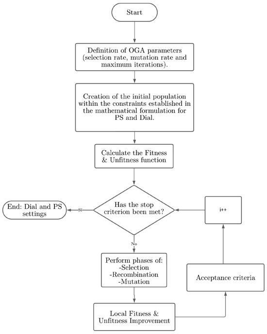
The optimized genetic algorithm (OGA) is an advanced version of Holland’s basic genetic algorithm, designed to maintain diversity among the chromosomes in the population throughout the evolutionary process. In each generation, only one chromosome is replaced, ensuring that it meets predefined criteria of optimality and/or feasibility. This approach ensures that the quality of the solution improves with each generation cycle. By systematically replacing a single offspring, the optimized genetic algorithm finds high quality solutions while preserving diversity within the population. The flowchart of the implemented optimized genetic algorithm is presented in Figure 1.
Figure 1.
Optimized GA flowchart.
The proposed OGA is formulated for radial distribution systems, which typically employ overcurrent relays as the primary protection mechanism. Although the present validation focuses on radial networks, the algorithm structure can be extended to meshed systems by incorporating additional coordination constraints and directional protection elements. This extension is identified as a future research direction. The parameters employed in this study, including population size, tournament size, and mutation rate, were selected based on established practices in evolutionary optimization applied to protection coordination problems and preliminary exploratory testing. Although a systematic sensitivity analysis is beyond the scope of this study, the selected values provide a balanced trade-off between convergence speed, solution quality, and computational efficiency, as evidenced by the consistent convergence observed across multiple independent executions.
3.1. Coding
In this paper, the variables TDS and PS are considered as decision variables in the optimization problem under the conditions proposed in Section 2.2. The chromosome structure is shown in Figure 2. Each chromosome is divided into two parts: one for selecting the TDS and one for selecting the PS.
Figure 2.
Example of an OGA chromosome.
The inverse-time curve type is defined as an input parameter at the beginning of the simulation and remains fixed during the optimization process. This choice is made to ensure consistency and comparability with the existing literature. However, the proposed algorithm is not restricted to a specific curve and can accommodate different inverse-time characteristics by appropriately defining the input data.
3.2. Creation of Initial Population
The algorithm initializes with the creation of an initial population of TDSs and PSs within the conditions of minimum and maximum TDS and minimum and maximum PS according to Equation (5). The critical aspect here is to ensure diversity, which means that the genetic composition of individuals in the population must be different. This diversity is critical, as it prevents stagnation in the population and ensures a wide exploration of the solution space. Algorithm 1 explains how the initial population is generated.
| Algorithm 1 Algorithm for population initialization (OGA) |
|
3.3. Fitness and Unfitness
The Fitness function is calculated according to Equation (1), this being the sum of the fault protection tripping times within its primary protection zone. The Unfitness function is related to the infeasibility of the solution; therefore, a penalty factor = is added if any constraint has been violated, otherwise = 0. Thus, when a violated constraint is found in the infeasible solution, it is also considered to be of low quality. The objective function is determined by combining the Fitness and Unfitness function as shown in Equation (8).
3.4. Selection
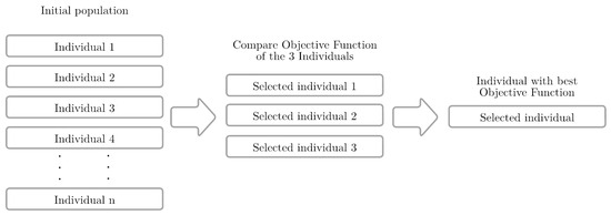
The OGA employs the tournament selection method, as seen in Figure 3, in which two tournaments are conducted with s individuals from the current population (where s is generally between 2 and 4); in the implementation using s = 3,this is represented by the selection rate. The process proceeds as follows: s individuals are randomly selected from the current population, their objective functions are compared, and the one with the best function is stored in the position reserved for parent number 1. Then, the process is repeated to determine parent number 2 and finally the same process for parent 3, making sure that all parents are different [27].
Figure 3.
Example of selection.
3.5. Recombination
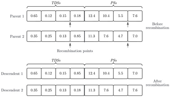
The exchange of genetic material between parents can be performed using single-point recombination, two-point recombination, or any other known recombination method [27]. In this work, single-point recombination was used, applied in conjunction for TDS and PS, as presented in Figure 4. After performing the recombination of the parents, two descendents are generated consisting of one part with the genetic material of parent number 1 and the other part with the genetic material of parent number 2. Subsequently, only the fittest (with the best objective function) continues the process.
Figure 4.
Example of recombination. The arrows indicate the cut-off points.
3.6. Mutation
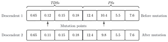
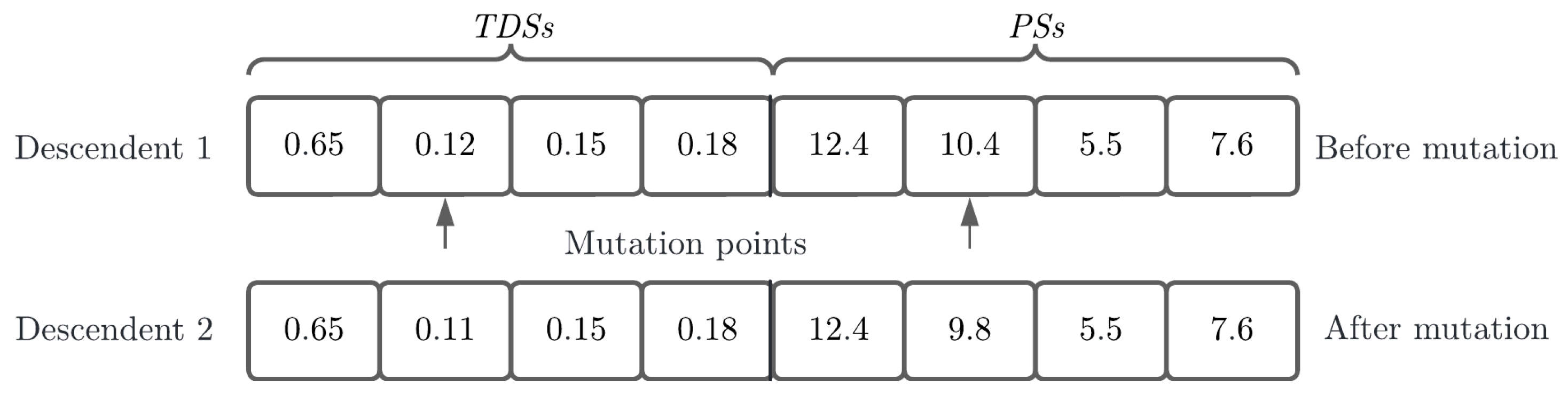
The descendent resulting from the recombination process is a vector that includes specific values in each of the positions related to the decision variables of the problem, thus introducing genetic diversity in the individual. During the mutation process, one of these positions is randomly selected to modify its content, either increasing or decreasing it. In this work, the mutation operator is applied jointly for TDS and PS. The number of mutated genes is related to the mutation rate defined in the OGA parameters. Mutated genes are given an addition or subtraction value as randomly determined by maintaining the conditions of TDS, Equation (4), and PS or Equations (5) and (6). An example of this is shown in Figure 5.
Figure 5.
Example of mutation. The arrows indicate the mutation points.
3.7. Local Improvement
Local improvement of an individual is one of the most significant contributions of the OGA and can be achieved in two ways: (1) By optimizing the objective function, and (2) by reducing infeasibility. Local improvement was performed in both ways.
After performing the selection, recombination, and mutation phases, a new descendent is generated, which can be either feasible or infeasible. If the new descendent is infeasible, this infeasibility is eliminated and the objective function is subsequently improved. If it is not infeasible, only the objective function is improved. In both cases, the objective is to improve the quality of the individual. In principle, the aim is to make the descendent feasible by modifying the TDS of the backup protection, increasing it by one step at a time. The local improvement mechanism operates using discrete adjustment steps defined by relay manufacturers. For the Siemens SIPROTEC 7SJ61 protection considered in this study, typical time dial setting (TDS) step sizes range from 0.01 to 0.05, depending on the selected curve and firmware configuration, while plug setting (PS) adjustments are performed in discrete current multiples defined by the protection pickup resolution. If an optimal solution is not found, one moves on to the TDS and PS of the primary protection, where a one-step increment is made, and then continues to test the TDS of the backup protection until one is found that will make the individual feasible. Finally, the objective function is improved by trying to decrease as much as possible the TDSs with that configuration of PS. Algorithm 2 explains how local improvement is performed.
| Algorithm 2 Local Improvement |
|
3.8. Acceptance Criteria
The new descendant enters the current population if it meets the following two criteria: (1) It must be different from all individuals already present in the population, thus ensuring genetic diversity within the population and avoiding duplicate solutions; and (2) the value of its objective function must be better than that of the individual with the worst OF, ensuring that the quality of the population improves with each iteration.
3.9. Stop Criteria
The algorithm will terminate when the maximum number of iterations specified in the algorithm parameters has been reached. This limit of iterations acts as a stopping criterion that ensures that the algorithm does not continue indefinitely. If, upon reaching this maximum number of iterations, no improved solution has been found or the current solution has not been modified, the algorithm terminates its execution, providing the best result obtained up to that point.
4. Tested System and Results
For the radial systems, a comparison is made between the results obtained and those of the literature, using the same conditions of topology, objective function, fault current levels, min and max values of primary tripping time, CTR, steps of PS, size of TDS, max and min limits of PS and TDS, and the characteristic curves of the protections. The simulations and the integration with the PowerFactory simulation software version 2024 SP1 (×64) were performed on computer with an Intel Core i5 2450 m 3.10 GHz processor, 12 Gb of RAM, a Windows 10 Pro 64 bit operating system, and Python 3.12 programming language through Jupyter Notebook version 7.5 integrated in Visual Studio Code version 1.91.
4.1. System I
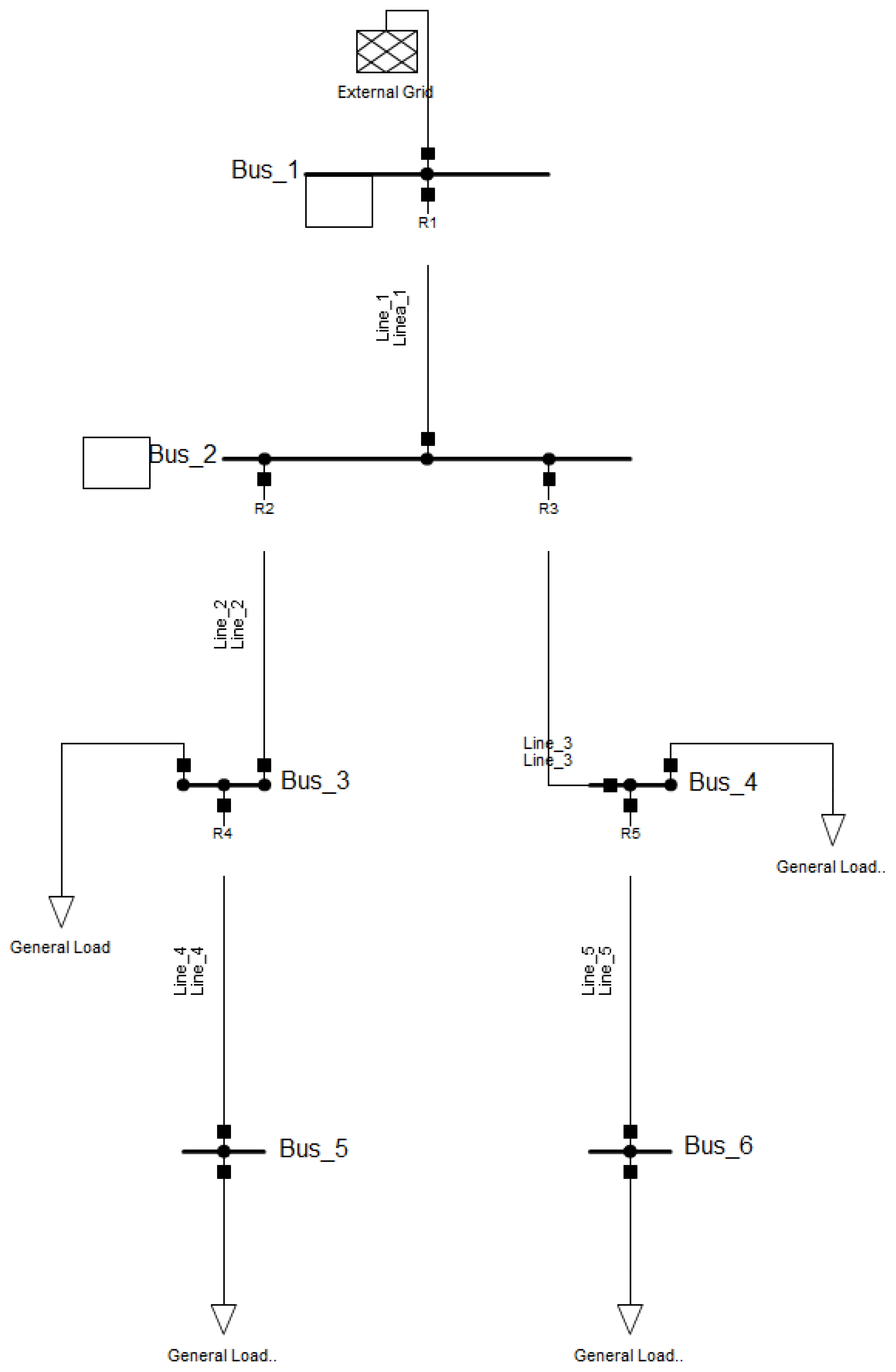
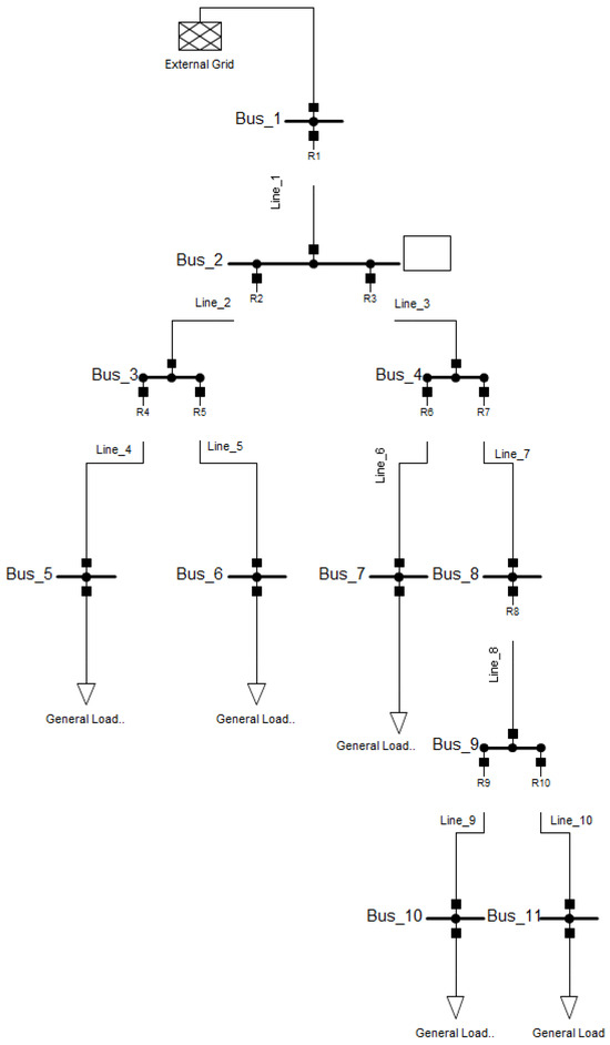
Figure 6 shows the single-line diagram created in the PowerFactory DigSILENT software version 2024 SP1 for the study case, similar to the one presented in [25]. For this study, the Siemens SIPROTEC 7SJ61 5A protection relay was used. The values adopted for the load factor (LF), , are 1.5 and 0.4 s, respectively. The protections follow the IEC standard and have a and of 0.1 and 10, respectively, with steps of 0.05. The can vary from 2.5 to 10 A, in steps of 0.75 A. and are taken as 0.05 and 2 s, respectively. This is in order to draw the most approximate model to the one proposed in the literature. In Table 3, the values of CTR, , type of curve, and minimum and maximum fault currents within its primary protection zone are presented for each protection using the IEC 60909 method of the short circuit study.
Figure 6.
System I elaborated in PowerFactory.
Table 3.
Values of CTR, , , , and curve types of System I relays.
First, the data is extracted with the help of the PowerFactory version 2024 SP1 Python library and then treated as input data for the optimized genetic algorithm to run. After that, the Optimized GA is run and finds the optimal values in the test system. Finally, the execution results and performance times are presented in Table 4 and Table 5, respectively.
Table 4.
Results of optimized genetic algorithm System I.
Table 5.
System I protection tripping times. Bold values indicate the tripping times corresponding to the fault location.
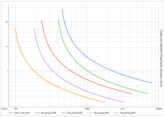
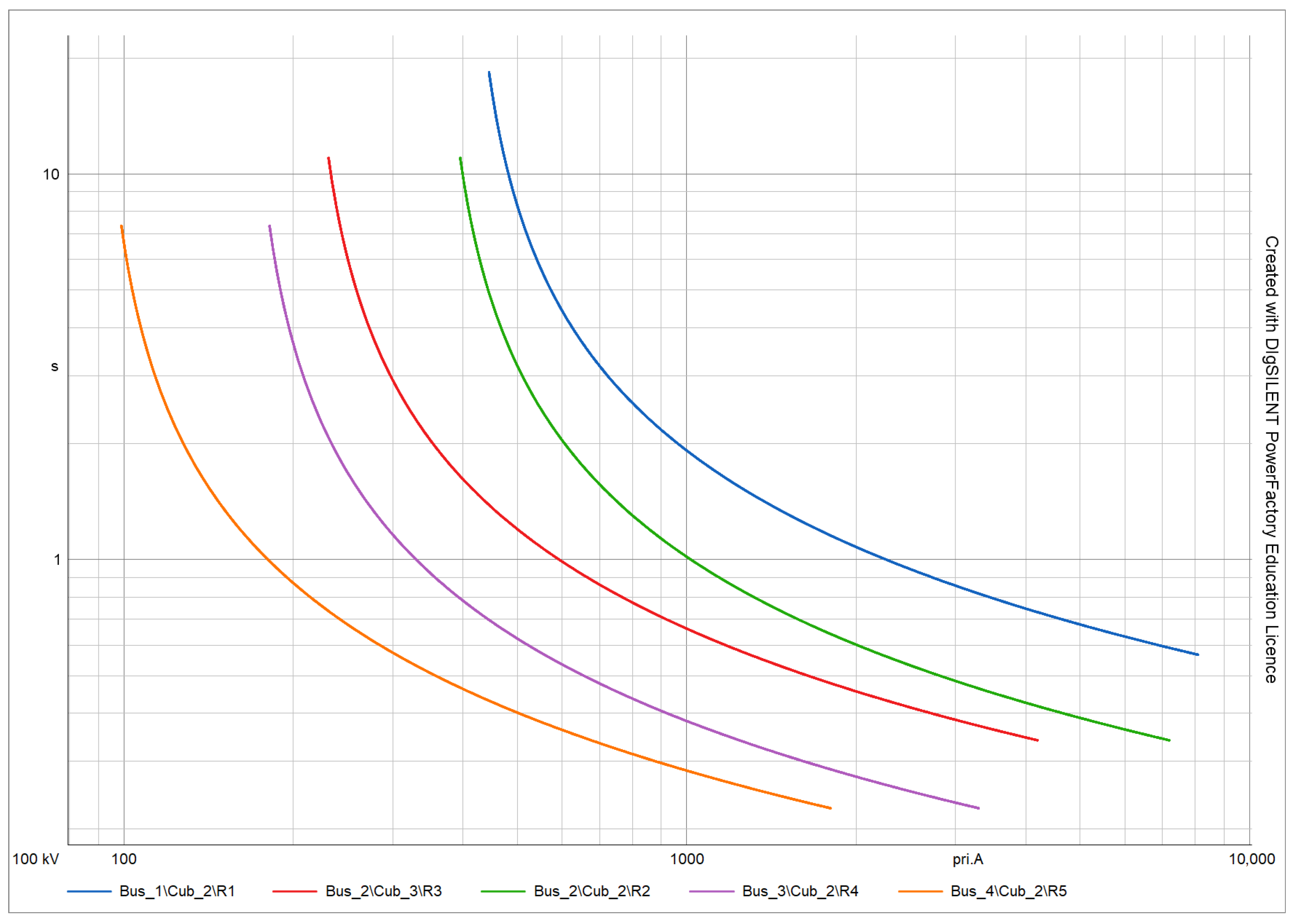
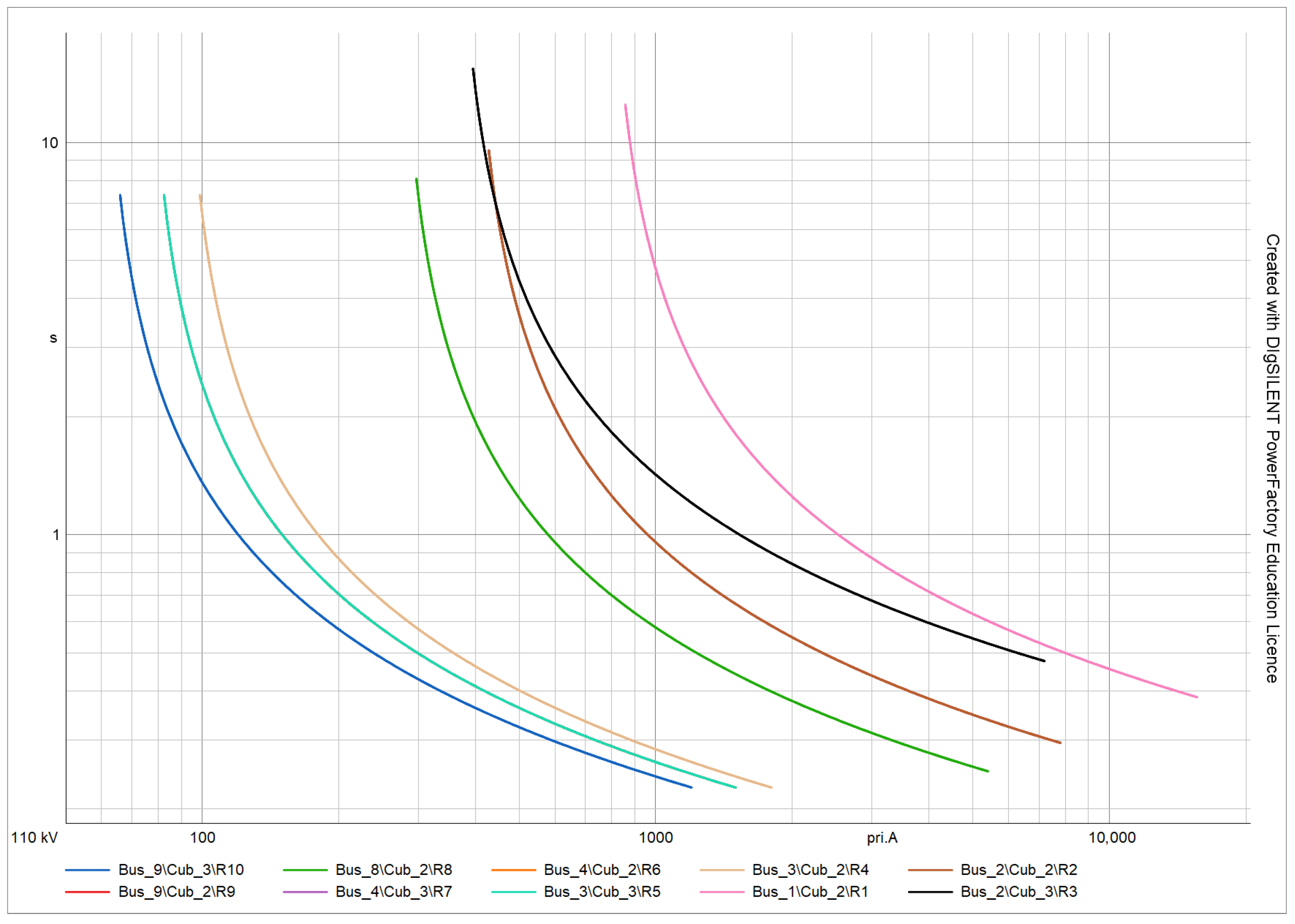
In Figure 7, the coordinogram provided by the PowerFactory software version 2024 SP1 is shown. This coordinogram shows that the system is selectively coordinated, which ensures that each protection device acts in the correct order to isolate only the section of the system affected by a fault, thus minimizing the impact on the rest of the electrical system. In addition, tripping times have been respected, ensuring that the devices closest to the source of the fault operate first, followed by upstream devices only if the fault persists. This allows for efficient and safe operation of the system, avoiding unnecessary interruptions and protecting equipment and facilities from damage.
Figure 7.
Coordinogram System I Optimized GA.
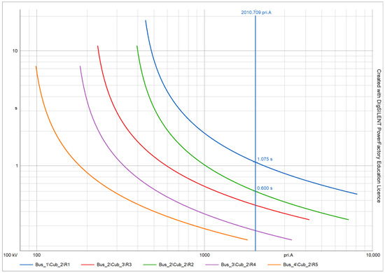
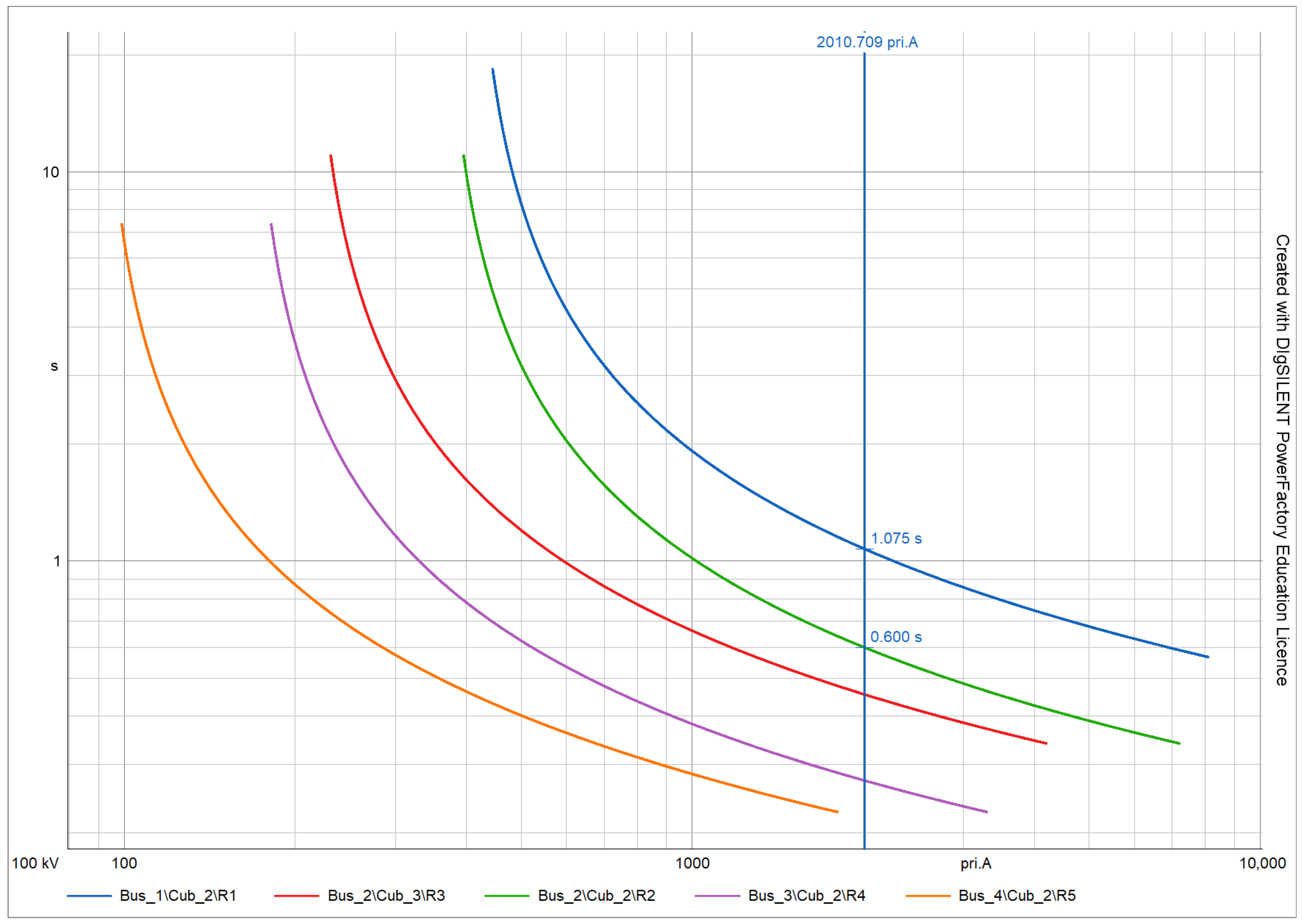
To validate the data, bus faults are simulated to determine if the system and the algorithm encounter the same tripping times. In Figure 8, a maximum short-circuit fault on Bar 3 and its tripping times are shown. The results obtained in the Optimized GA execution for this system, contained in Table 5, indicate that for a short-circuit with maximum three-phase current, protection will trip in 0.6000 s and, if it does not trip, protection will enter as backup, tripping in 1.0747 s, validating that the data obtained coincide with those simulated.
Figure 8.
Fault on Bar 3 Simulated system I Optimized GA.
4.2. System II
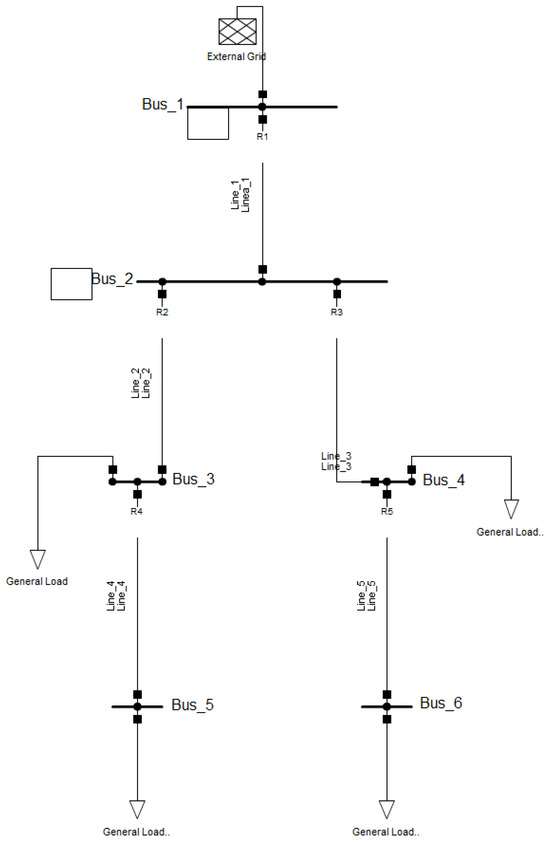
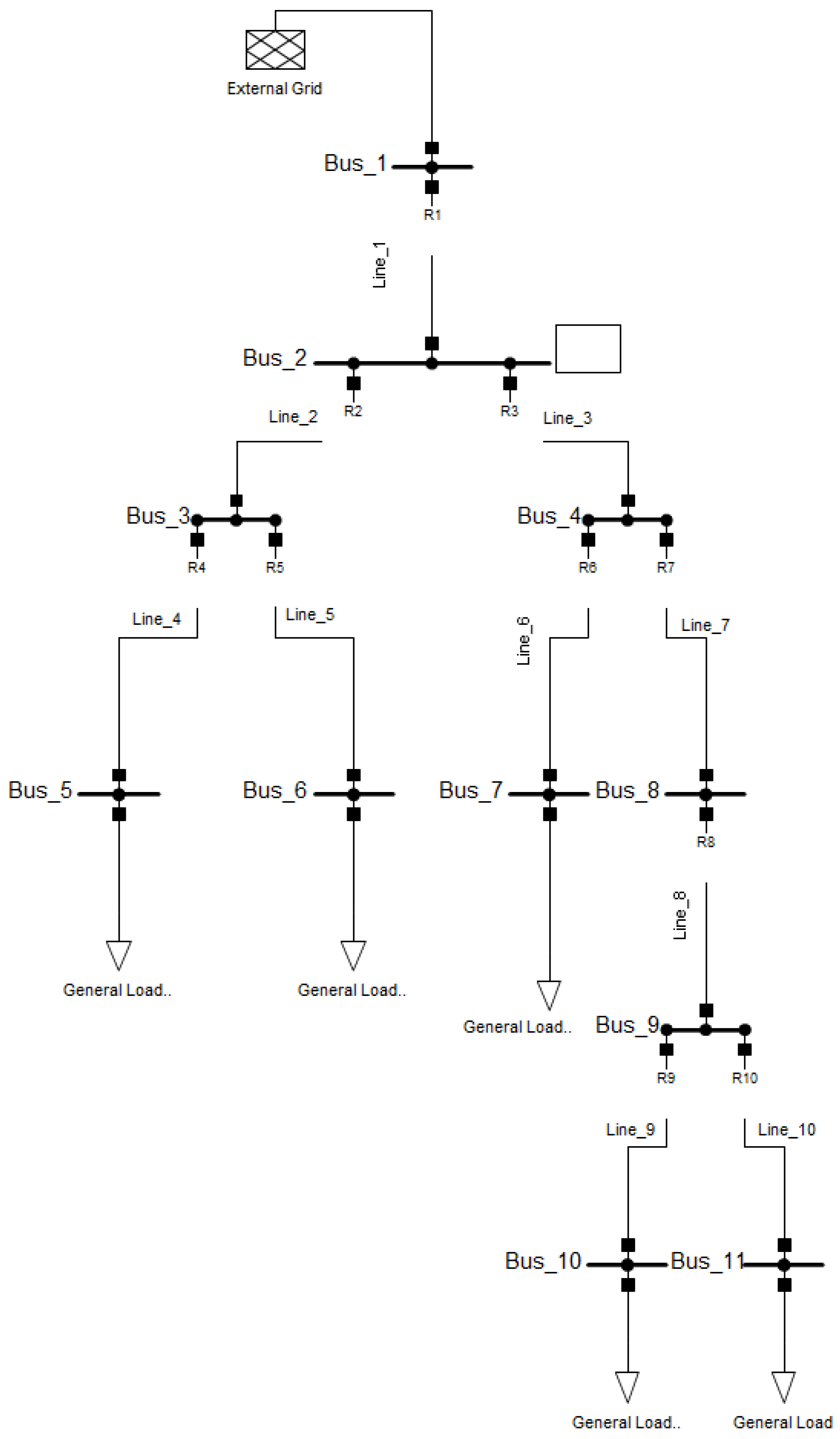
Figure 9 shows the single-line diagram created in the PowerFactory DigSILENT version 2024 SP1 software for the study case, similar to the one presented in [25]. For this study, the Siemens SIPROTEC 7SJ61 5A protection relay was used. The values adopted for the load factor (LF) and are 1.5 and 0.4 s, respectively. The relays follow the IEC standard and have a and a of 0.1 and 10, respectively, with steps of 0.01. The PS can vary from 2.5 to 10 A in steps of 0.75 A. and are considered to be 0.05 and 2 s, respectively. This is in order to draw the most approximate model to the one proposed in the literature. In Table 6, the values for CTR, , curve type, and minimum and maximum fault currents within its primary protection zone are presented for each protection using the IEC 60909 [28] short-circuit study method.
Figure 9.
Tested system elaborated in PowerFactory.
Table 6.
Values of CTR, , , and curve types of System II protections elaborated in PowerFactory DigSILENT.
In the same way as System I, the data for System II are obtained using the PowerFactory version 2024 SP1 library in Python. Then, these data are processed as inputs to run the optimized genetic algorithm. After running the Optimized GA and determining the optimal values in the test system, the results of the configurations are shown in Table 7 and the results of the actuation times are shown in Table 8.
Table 7.
Results OGA Tested system.
Table 8.
Actuation times of Tested system protections. Bold values indicate the tripping times corresponding to the fault location.
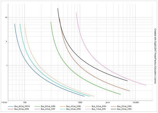
Figure 10 shows the coordinogram generated by the PowerFactory software. Since some values of TDS and are identical, due to their similarity in short circuit currents, some of the curves are overlapped. This coordinogram shows that the system is selectively coordinated, ensuring that each protective device acts in the correct order to isolate only the section of the system affected by a fault, thus minimizing the impact on the rest of the electrical system. In addition, tripping times have been respected, ensuring that the devices closest to the source of the fault operate first, followed by upstream devices only if the fault persists.
Figure 10.
Coordinogram System II Optimized GA.
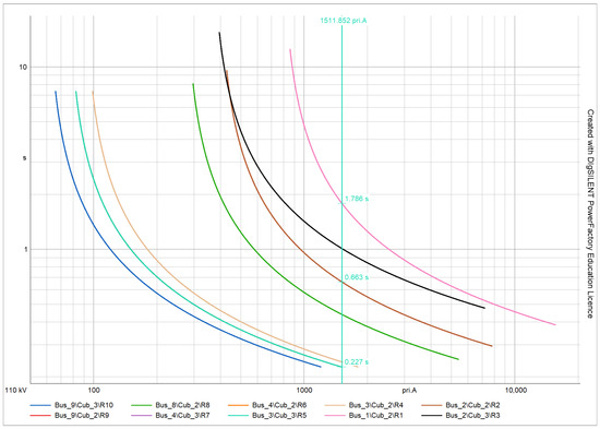
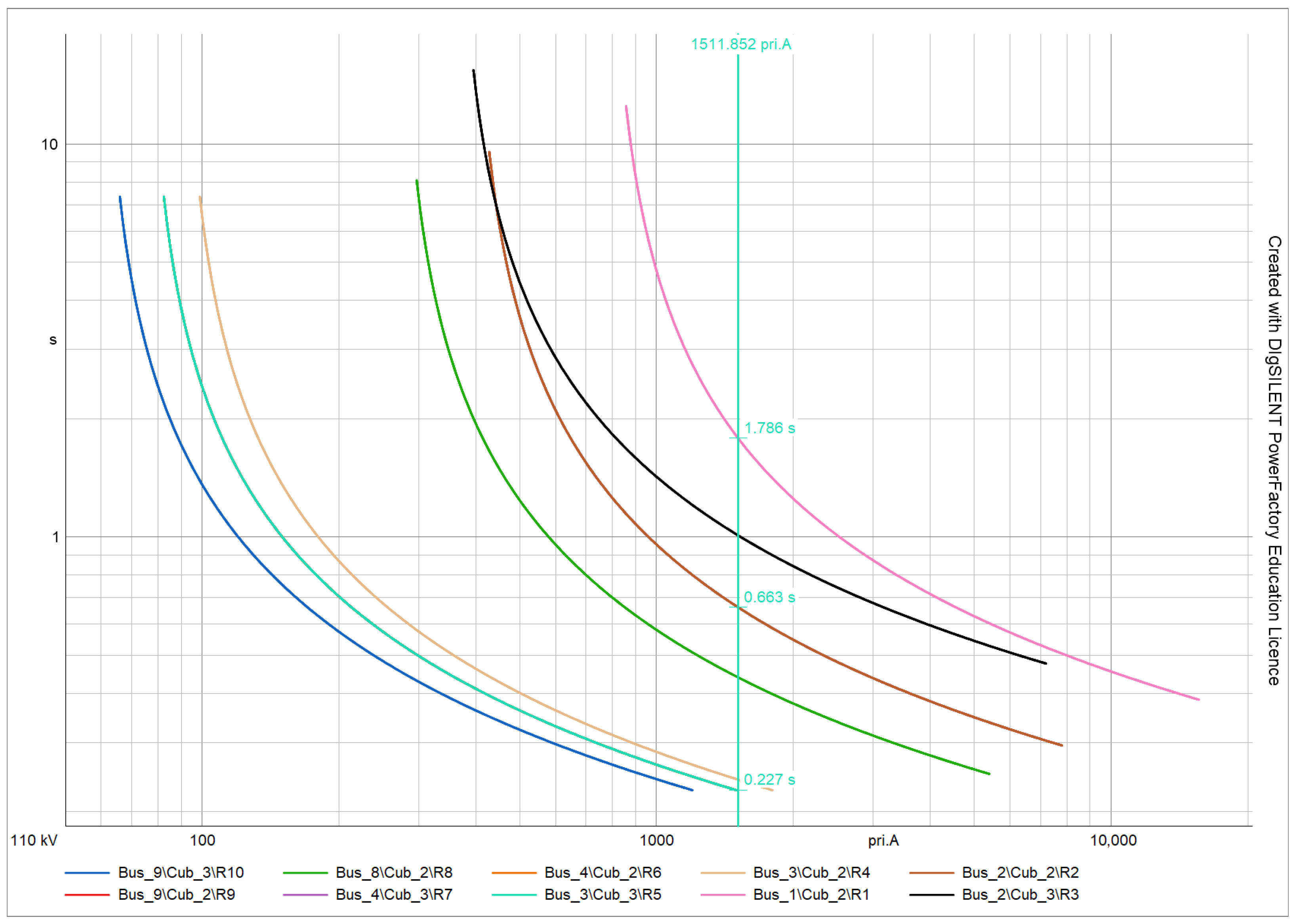
To validate the data obtained in Table 8, simulations of bus faults are performed to verify if the system and the algorithm determine the same tripping times. In Figure 11, a maximum short-circuit fault at Bus 6 is shown along with its trip times. The results obtained by running the Optimized GA for this system indicate that, for a short-circuit with maximum three-phase current, protection will trip in 0.227 s and, if it does not trip, protection will trip as a backup in 0.663 s, confirming that the data obtained coincide with the simulated ones; in the coordinogram, it can also be seen that if these two do not trip, will trip 1.786 s after the fault has occurred, respecting the times 0.4 s that must exist between protections.
Figure 11.
Fault in Bus 6 System II Optimized GA.
4.3. Method Validation
The algorithm was executed 100 times to evaluate its robustness and reliability. Accordingly, 100 simulations were performed for both System I and System II, each starting from different initial points, with a population size of 40, a tournament selection size of 3, and a mutation rate of 2. The minimum, average, and maximum values, as well as the standard deviations of the objective function values and the computational execution times required during the 100 iterations of the Optimized GA for System I and System II, are presented in Table 9 and Table 10.
Table 9.
Statistics of the 100 executions of the Optimized GA for System I.
Table 10.
Statistics of the 100 executions of the Optimized GA for System II.
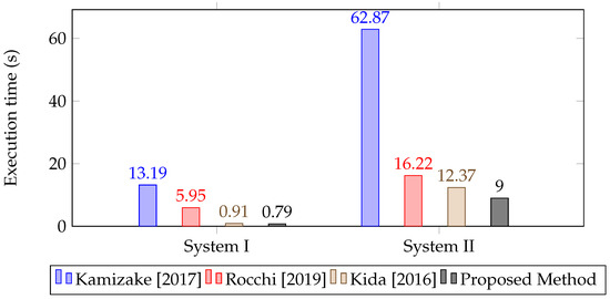
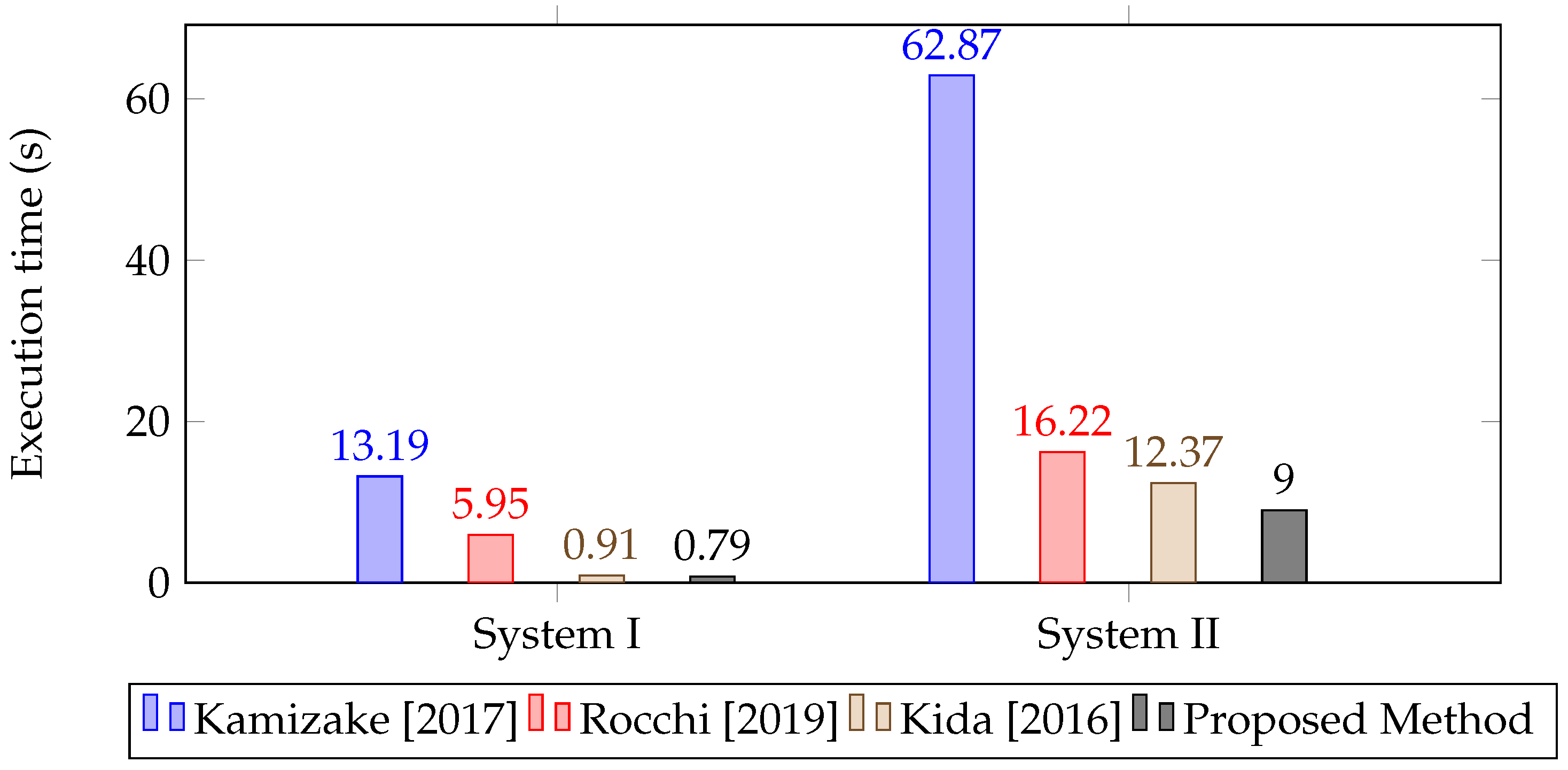
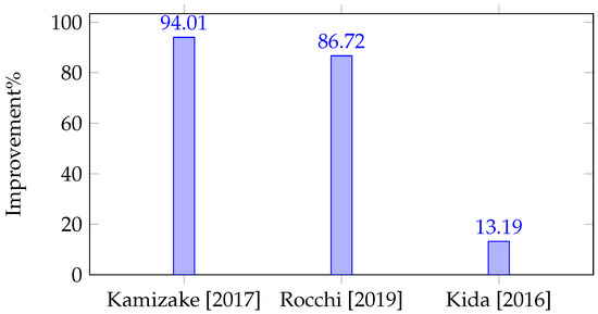
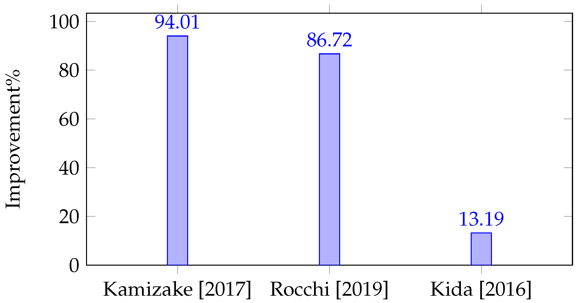
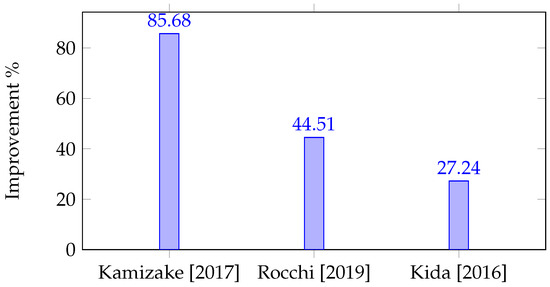
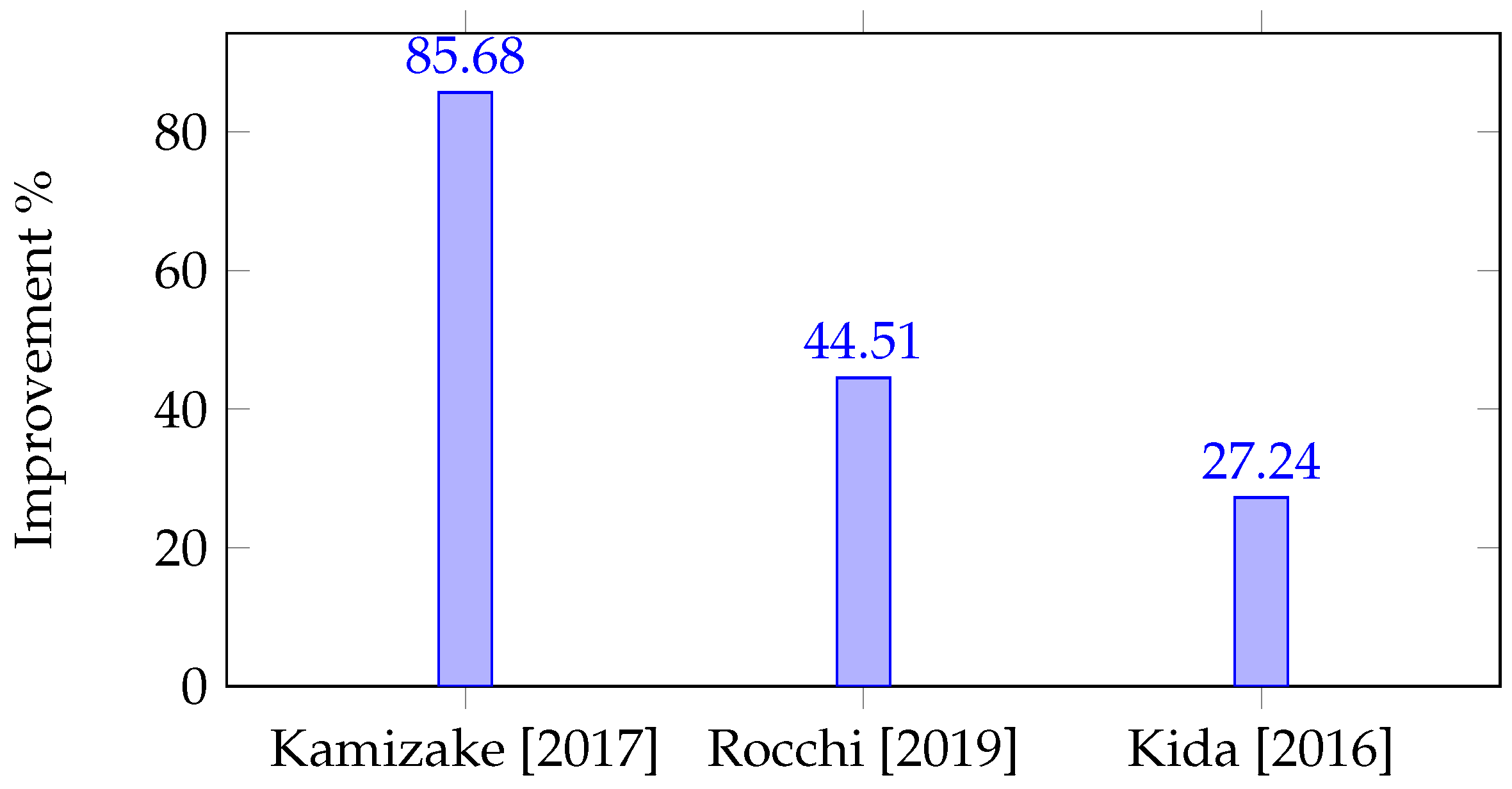
Considering that the Optimized GA does not include mixed techniques like those used by Kida [25], Rocchi [17], and Kamizake [15], it shows a higher standard deviation in the objective function (OF) due to its inherent randomness. However, since it does not rely on linear programming to obtain the s and instead incorporates an optimal local improvement strategy, the method proves to be more efficient in terms of computational execution time, achieving optimal results in shorter periods. As observed in Figure 12, the execution times of the Optimized GA for solving the overcurrent protection coordination problem are lower than those reported in the literature. Also, the percentage of time improvement illustrated in Figure 13 and Figure 14 is more than 13% in System I, and more than 27% in System II. It is noteworthy that these execution times are relative, as they depend on the processor and RAM of the computer, as well as on the software environment used to implement and solve the problem (e.g., Python, MATLAB, or C/C++). Thus, this comparison is not entirely fair. To perform a more equitable comparison, all algorithms or solution methods should be implemented in the same software environment and executed on the same computer.
Figure 12.
Execution times of methods from the literature, including the proposed method, for System I and System II. Kamizake [15], Rocchi [17], and Kida [25].
Figure 13.
Percentage of execution time improvement of the Optimized GA compared to existing methods, System I. Kamizake [15], Rocchi [17], and Kida [25].
Figure 14.
Percentage of execution time improvement of the Optimized GA compared to existing methods, System II. Kamizake [15], Rocchi [17], and Kida [25].
It should be noted that execution time comparisons with literature methods must be interpreted cautiously, as different implementation environments and programming languages can influence absolute runtimes. The objective of this comparison is therefore to provide an indicative assessment of computational efficiency rather than a strict benchmark.
5. Discussion
This study demonstrates that metaheuristic algorithms, particularly the optimized genetic algorithm, can effectively coordinate overcurrent protections with high accuracy and reduced computational time compared to traditional or mixed LP-based methods. This optimized methodology simplifies the configuration process while ensuring the selectivity and reliability of the protection system, confirming that heuristic techniques can automate protection settings efficiently and consistently. The proposed method opens new research perspectives, especially regarding its integration with digital twin frameworks and hardware-in-the-loop platforms, to enable real-time, adaptive configuration of overcurrent protections in smart and dynamically changing power systems.
Although the validation in this study is performed on radial distribution systems, the proposed OGA formulation is not inherently limited to radial topologies. In meshed or ring networks, the coordination problem can be extended by incorporating directional overcurrent elements and defining multiple primary–backup relationships for each fault scenario. The objective function and constraint structure remain unchanged, while the protection graph expands to include bidirectional coordination paths.
Similarly, while fixed inverse-time curves are assumed in this work to ensure comparability and reduce the solution space, the curve type can be incorporated as an additional discrete decision variable. This extension would allow the optimization to select among inverse, very inverse, or extremely inverse curves based on system characteristics. Such enhancements are identified as promising directions for future research.
The presence of distributed energy resources introduces variability in fault current magnitude and direction, which can invalidate fixed protection settings. While this study assumes static fault levels derived from IEC 60909, the proposed OGA can easily adapt to DER-integrated systems by updating fault current inputs for different operating scenarios. This capability enables scenario-based or adaptive protection coordination and aligns with emerging smart grid and digital twin concepts.
6. Conclusions
Unlike methods proposed in the literature, the Optimized GA does not rely on linear programming techniques, achieving greater computational efficiency by avoiding additional calculations. As shown in Figure 13 and Figure 14, while the execution time of mixed methods increases as more buses are added to the problem, the proposed method consistently outperforms them, reducing execution time by over 13% in smaller systems and more than 27% in larger and more complex networks. This improvement results from the simplified implementation of the algorithm, which eliminates the need to solve additional linear programming problems. By eliminating the complexity of mixed techniques, the Optimized GA operates more efficiently, resulting in faster processing times and more streamlined solution discovery. Also, the use of simplified yet consistently effective techniques, such as the one presented in Section 3.7, shows that local refinement improvements can significantly enhance the convergence and feasibility of metaheuristic algorithms without increasing computational complexity.
The optimized algorithm presented in this article can be of great help to researchers in the field, as it complements the algorithms already available in the specialized literature.
The results confirm that the algorithm accurately determines the timing of relay device trips, ensuring that the system responds appropriately to faults. By maintaining the necessary time intervals between relays, the Optimized GA effectively provides an excellent solution to the overcurrent relay coordination problem and enhances the reliability of the electrical system. This validation underscores the robustness of the algorithm in managing fault scenarios, reinforcing its practical applicability in ensuring network stability and safety.
The validation of the Optimized GA with PowerFactory DigSILENT software demonstrates that this type of heuristic technique for overcurrent protection coordination is highly effective. The use of the GA allows for greater flexibility in the configuration of protection settings, better adapting to the variations and complexities of the electrical system. This methodology not only optimizes the operating parameters but also reduces the response time to faults, minimizing the impact on the network and improving service continuity.
Author Contributions
Conceptualization, methodology, M.A.L.V., E.G.-L. and L.A.G.P.; validation, E.G.-L., L.A.G.P. and J.C.V.; investigation, M.A.L.V.; writing—original draft preparation, M.A.L.V.; writing—review and editing, M.A.L.V., E.G.-L., L.A.G.P. and J.C.V.; supervision, E.G.-L., L.A.G.P. and J.C.V. All authors have read and agreed to the published version of the manuscript.
Funding
This research received no external funding.
Data Availability Statement
The original contributions presented in this study are included in the article. Further inquiries can be directed to the corresponding author.
Conflicts of Interest
The authors declare no conflicts of interest.
References
- Gómez-Luna, E.; Candelo-Becerra, J.E.; Vasquez, J.C. A New Digital Twins-Based Overcurrent Protection Scheme for Distributed Energy Resources Integrated Distribution Networks. Energies 2023, 16, 5545. [Google Scholar] [CrossRef] [Scilit]
- Garibello-Narváez, D.R.; Gómez-Luna, E.; Vasquez, J.C. Performance Evaluation of Distance Relay Operation in Distribution Systems with Integrated Distributed Energy Resources. Energies 2024, 17, 4735. [Google Scholar] [CrossRef] [Scilit]
- De La Cruz, J.; Vasquez, J.C.; Guerrero, J.M.; Luna, E.G.; Candelo-Becerra, J.E. Adaptive Multi-Agent-Zonal Protection Scheme for AC Microgrids. In 2023 25th European Conference on Power Electronics and Applications (EPE’23 ECCE Europe), Aalborg, Denmark, 4–8 September 2023; IEEE: Piscataway, NJ, USA, 2023; pp. 1–9. [Google Scholar]
- Glover, J.; Overbye, T.; Sarma, M. Power System Analysis and Design; Cengage Learning: Boston, MA, USA, 2016. [Google Scholar]
- Albrecht, R.E.; Nisja, M.J.; Feero, W.E.; Rockefeller, G.D.; Wagner, C.L. Digital Computer Protective Device Co-ordination Program I-General Program Description. IEEE Trans. Power Appar. Syst. 1964, 83, 402–410. [Google Scholar] [CrossRef] [Scilit]
- Figueroa Orihuela, W.R. Análisis y Estudio de las Protecciones Contra Sobrecorriente en Sistemas de Energía Eléctrica. Bachelor’s Thesis, Universidade Estadual de Londrina, Londrina, Brazil, 2009. [Google Scholar]
- Urdaneta, A.J.; Nadira, R.; Jimenez, L.P. Optimal coordination of directional overcurrent relays in interconnected power systems. IEEE Trans. Power Deliv. 1988, 3, 903–911. [Google Scholar] [CrossRef] [Scilit]
- Elrafie, H.; Irving, M. Linear programming for directional overcurrent relay coordination in interconnected power systems with constraint relaxation. Electr. Power Syst. Res. 1993, 27, 209–216. [Google Scholar] [CrossRef] [Scilit]
- Chattopadhyay, B.; Sachdev, M.; Sidhu, T. An online relay coordination algorithm for adaptive protection using linear programming technique. IEEE Trans. Power Deliv. 1996, 11, 165–173. [Google Scholar] [CrossRef] [Scilit]
- Zapata, C.J.; Mejía, G.E. Coordinación de relés de sobrecorriente en sistemas radiales utilizando programación lineal. Sci. Tech. 2003, 2, 1–6. [Google Scholar]
- Estrada, N.J.; Carmona, O.G.; Ruiz, A.G. Coordinación de relés de sobrecorriente usando el método de optimización de puntos interiores. Sci. Tech. 2006, 12, 25–30. [Google Scholar]
- Bedekar, P.P.; Bhide, S.R.; Kale, V.S. Optimum coordination of overcurrent relays in distribution system using dual simplex method. In 2009 Second International Conference on Emerging Trends in Engineering & Technology, Maharashtra, India, 16–18 December 2009; IEEE: Piscataway, NJ, USA, 2009; pp. 555–559. [Google Scholar]
- Niyomphant, S.; Leeton, U.; Kulworawanichpong, T.; Chomnawang, N. Application of linear programming for optimal coordination of directional over-current relays. In 2012 9th International Conference on Electrical Engineering/Electronics, Computer, Telecommunications and Information Technology, Phetchaburi, Thailand, 16–18 May 2012; IEEE: Piscataway, NJ, USA, 2012; pp. 1–4. [Google Scholar]
- Kida, A.A.; Echavarria, A.F.A.; Machado, S.d.J.M.; Pareja, L.A.G. Algoritmos Heurísticos Aplicados ao Planejamento de Redes de Transmissão. In Proceedings of the XLVII Simpósio Brasileiro de Pesquisa Operacional (SBPO 2015), Londrina, Brazil, 25–28 August 2015. [Google Scholar]
- Kamizake, A. Algoritmos Heurísticos Combinados à Programação Linear para a Solução da Coordenação de Relés de Sobrecorrente. Bachelor’s Thesis, Universidade Estadual de Londrina, Londrina, Brazil, 2017. [Google Scholar]
- Souza, L.A.; Silva, C.L.; Calixto, W.P. Optimized setting of directional overcurrent relays via genetic algorithm. In 2018 Simposio Brasileiro de Sistemas Eletricos (SBSE); IEEE: Piscataway, NJ, USA, 2018; pp. 1–6. [Google Scholar]
- Rocchi, R.B. Algoritmo de Busca Tabu Combinado à Programação Linear para Solução da Coordenação de Relés de Sobrecorrente. Bachelor’s Thesis, Universidade Estadual de Londrina, Londrina, Brazil, 2019. [Google Scholar]
- Rivas, A.E.L.; Pareja, L.A.G.; Abrão, T. Coordination of distance and directional overcurrent relays using an extended continuous domain ACO algorithm and an hybrid ACO algorithm. Electr. Power Syst. Res. 2019, 170, 259–272. [Google Scholar] [CrossRef] [Scilit]
- El-Fergany, A.A.; Hasanien, H.M. Water cycle algorithm for optimal overcurrent relays coordination in electric power systems. Soft Comput. 2019, 23, 12761–12778. [Google Scholar] [CrossRef] [Scilit]
- Tiwari, R.; Singh, R.K.; Choudhary, N.K. A comparative analysis of optimal coordination of distance and overcurrent relays with standard relay characteristics using GA, GWO and WCA. In 2020 IEEE Students Conference on Engineering & Systems (SCES), Prayagraj, India, 10–12 July 2020; IEEE: Piscataway, NJ, USA, 2020; pp. 1–6. [Google Scholar]
- Meira, R.N.; de Araújo Pereira, R.L.; Brito, N.S.D. A new method for optimal coordination of overcurrent and distance relays. J. Control Autom. Electr. Syst. 2023, 34, 858–871. [Google Scholar] [CrossRef] [Scilit]
- Gairola, E.; Rawat, M.S. Optimum Coordination and Settings of Overcurrent Relays using Teaching Learning based Optimization in a Distribution System. In 2023 IEEE 8th International Conference for Convergence in Technology (I2CT), Pune, India, 7–9 April 2023; IEEE: Piscataway, NJ, USA, 2023; pp. 1–5. [Google Scholar]
- Mohamedshareef, R.; Abapour, M.; Hosseini, S.H.; Seyydi, H. Optimizing directional overcurrent relay coordination with jellyfish search algorithm. Electr. Eng. 2024, 106, 7103–7115. [Google Scholar] [CrossRef] [Scilit]
- Zerka, A.; Ouassaid, M. Enhancing Adaptive Protection for Microgrids through Digital Twin Technology and a Game Theory Based Approach. In 2025 7th Global Power, Energy and Communication Conference (GPECOM), Bochum, Germany, 11–13 June 2025; IEEE: Piscataway, NJ, USA, 2025; pp. 773–778. [Google Scholar] [CrossRef] [Scilit]
- Kida, A.A. Metodologias para Coordenação de Relés de Sobrecorrente Utilizando Técnicas de Otimização Matemática. Master’s Thesis, Universidade Estadual de Londrina, Londrina, Brazil, 2016; p. 222. [Google Scholar]
- IEC 60255-151; Measuring Relays and Protection Equipment—Part 151: Functional Requirements for Over/Under Current Protection. International Electrotechnical Commission: Geneva, Switzerland, 2009.
- Rendón, R.; Zuluaga, A.; Ocampo, E. (Eds.) Técnicas Heurísticas y Metaheurísticas; Colección Trabajos de Investigación; Universidad Tecnológica de Pereira: Pereira, Colombia, 2016. [Google Scholar]
- IEC 60909-0; Short-Circuit Currents in Three-Phase a.c. Systems—Part 0: Calculation of Currents. International Electrotechnical Commission: Geneva, Switzerland, 2016.




Disclaimer/Publisher’s Note: The statements, opinions and data contained in all publications are solely those of the individual author(s) and contributor(s) and not of MDPI and/or the editor(s). MDPI and/or the editor(s) disclaim responsibility for any injury to people or property resulting from any ideas, methods, instructions or products referred to in the content. |
© 2026 by the authors. Licensee MDPI, Basel, Switzerland. This article is an open access article distributed under the terms and conditions of the Creative Commons Attribution (CC BY) license.