


Abstract
Growing wind and photovoltaic generation increases the demand for large-scale, long-duration energy storage. Pumped hydro compressed-air energy storage (PHCAES) stores and releases energy through pressure transfer between water and compressed air, using air pressure to provide an equivalent hydraulic head and thereby reducing dependence on natural elevation while retaining hydraulic energy conversion and the potential for near-isothermal operation. This review establishes a taxonomy of hydraulically coupled compressed-air storage comprising PHCAES, liquid-piston systems, hydraulically compensated constant-pressure CAES, and hydraulic–pneumatic cascade or hybrid systems. Variable- and constant-pressure PHCAES are compared with pumped hydro energy storage (PHES) and compressed-air energy storage (CAES) in terms of efficiency, economics and environmental implications; this is followed by a critical analysis of the mechanisms governing PHCAES performance. The results show that improved siting flexibility is the principal conditional advantage of PHCAES, rather than inherently higher efficiency or lower cost. Its net performance depends on pressure–volume matching, gas–liquid heat transfer, hydraulic-machine operation, auxiliary consumption and storage infrastructure. Pressure regulation and thermal enhancement are beneficial only when their gains exceed the associated compression, throttling and auxiliary losses. The principal research gap is the lack of engineering-scale, full-cycle validation using consistent electrical, economic and lifecycle assessment boundaries, which currently prevents robust comparison with PHES and CAES.
1. Introduction
Driven by mounting environmental pollution and the global energy crisis, the energy sector is undergoing an accelerated transition toward low-carbon development, accompanied by continued growth in both renewable power capacity and its share of electricity generation [1]. According to the International Renewable Energy Agency (IRENA), global renewable power capacity reached 5149 GW in 2025, with 692 GW of new capacity added during the year. Solar and wind power dominated this expansion, together accounting for 670 GW of newly installed capacity. However, wind and solar resources are highly dependent on meteorological conditions and exhibit stochastic, intermittent, and variable characteristics, making their power output difficult to forecast accurately [2,3]. As the penetration of wind and solar power increases, maintaining real-time power balance becomes increasingly challenging, posing substantial risks to the secure and stable operation of power systems [4,5]. By enabling energy shifting across time and space and balancing electricity supply and demand, energy storage has become a key technology for mitigating wind and solar power fluctuations, enhancing grid reliability, and improving power-system flexibility [6,7].
Current energy storage technologies can be broadly classified into mechanical energy storage [8,9], electrochemical energy storage [10,11], electromagnetic energy storage [12,13], thermal energy storage [14,15], and hydrogen energy storage [16,17]. These technologies differ substantially in response time, energy density, power density, and other performance characteristics, resulting in distinct operational capabilities and application scenarios. Among them, pumped hydro energy storage [18,19] and compressed air energy storage [20,21] are regarded as two of the most promising long-duration energy storage technologies for large-scale deployment because of their large storage capacities and long service lives.
Pumped hydro energy storage (PHES), currently the largest energy storage technology by deployment scale, accounts for approximately 80% of global installed energy storage capacity and more than 90% of the total energy stored. During off-peak periods, electricity is used to pump water from a lower reservoir to an upper reservoir, thereby converting electrical energy into gravitational potential energy. During peak-demand periods, the stored water is released through hydraulic turbines to regenerate electricity [22]. Accordingly, the energy storage capacity of a PHES plant is primarily determined by the usable reservoir volume and the hydraulic head between the upper and lower reservoirs [23]. Mainstream PHES configurations include conventional fixed-speed systems, variable-speed systems, and ternary systems with separate pumping and generating units [24,25,26]. However, the deployment of conventional PHES is strongly constrained by topographic relief, water availability, and environmental considerations. Consequently, alternative configurations—including closed-loop or off-river PHES [27], underground or abandoned-mine PHES [28], seawater PHES [29], and offshore PHES [30]—have attracted increasing attention. By using purpose-built reservoirs or repurposing spatial resources such as abandoned mines and offshore or deep-sea environments, these configurations broaden the range of feasible sites and potential applications.
Compressed air energy storage (CAES) uses surplus electricity to drive compressors, with the compressed air stored in underground caverns, salt caverns, aquifers, or other suitable geological formations. During discharge, the high-pressure air is released and expanded through a turbine to generate electricity. Early diabatic CAES systems reject the heat generated during compression and burn natural gas to reheat the air before expansion. Consequently, they are characterised by relatively low round-trip efficiencies of approximately 48–54%, dependence on fossil fuels, and strong reliance on suitable geological storage sites, which have limited their wider deployment [31]. To overcome these limitations, several advanced CAES configurations have been proposed. Adiabatic CAES systems recover and store compression heat in thermal energy storage units for subsequent reuse, enabling round-trip efficiencies of approximately 65–75% [32]. Isothermal CAES systems enhance heat transfer through water spraying, foams, liquid pistons, porous media, or enlarged heat-transfer surfaces, thereby maintaining compression and expansion processes close to isothermal conditions. This approach reduces compression work and limits the temperature drop during expansion [33,34]. Other emerging concepts, including liquid air energy storage [35], supercritical compressed air energy storage [36], and underwater compressed air energy storage [37], have further broadened the technological scope of compressed-gas energy storage by increasing energy density, exploiting alternative thermodynamic states or working media, and enabling near-constant-pressure storage.
To reduce the topographic constraints of conventional PHES, pumped hydro combined with compressed air energy storage (PHCAES) uses compressed-air pressure to establish an equivalent hydraulic head [38]. During charging, water is pumped into a pressurised water–air chamber to compress the air; during discharge, the expanding air drives water through a hydraulic turbine. By replacing natural elevation differences with gas pressure, PHCAES reduces dependence on substantial topographic relief and may reduce the need for large, elevated reservoirs, thereby broadening potential siting options [39]. Compared with conventional CAES, direct water-displacement PHCAES relies primarily on hydraulic machinery for energy conversion, while heat exchange between water and air can promote near-isothermal compression and expansion under suitable operating conditions [40]. These features offer opportunities to reduce thermal losses and temperature excursions, although the resulting electrical efficiency remains dependent on hydraulic-machine performance, auxiliary consumption and pressure regulation.
Building on this water–air coupling principle, subsequent research has explored different approaches to pressure control, thermal management and system integration. Near-isothermal–isobaric storage and spray-assisted liquid-piston studies have investigated ways to combine pressure regulation with improved gas–liquid heat transfer [41,42]. Other studies have developed pump-compressed-air and micro-hydroturbine systems, large-scale pumped compressed-air concepts and steam-regulated constant-pressure configurations [43,44,45]. Solar-assisted storage and hydraulically coupled compressed-carbon-dioxide systems further extend the concept to external heat input and alternative working fluids [46,47]. Collectively, these studies show that the liquid may serve as a displacement piston, pressure compensator, heat-transfer medium or hydraulic energy carrier. Because these functions lead to different machinery chains, pressure characteristics and performance boundaries, they require a classification broader than PHCAES alone.
Previous reviews provide a foundation for this broader scope. Gouda et al. [48] examined liquid-piston CAES, focusing on transient fluid flow, heat transfer and thermal-enhancement methods. Hao et al. [49] addressed near-isothermal mechanisms, integrated applications and commercialisation challenges, while Yang et al. [39] reviewed six hydraulic compressed-air storage configurations, their operating principles, applications and technical bottlenecks. Building on these contributions, the present review compares PHCAES with PHES and CAES in terms of efficiency, economics and environmental implications, and examines the mechanisms and design trade-offs governing PHCAES performance. Table 1 summarises how this combined focus complements existing reviews, with particular attention to differences in evaluation boundaries and the distinction between experimental evidence and model predictions.
Table 1.
Comparison of previous reviews and the present review.
The literature search covered Scopus, ScienceDirect, IEEE Xplore and the China National Knowledge Infrastructure (CNKI) for records available up to September 2026. To capture both the broader energy-storage context and the technologies examined in this review, the search strategy combined general terms, including “renewable energy”, “long-duration energy storage”, “pumped hydro energy storage” and “compressed air energy storage”, with system-specific terms such as “pumped hydro compressed air energy storage”, “PHCAES”, “hydraulic compressed air energy storage”, “hydro-pneumatic energy storage”, “liquid piston compressed air energy storage”, “constant-pressure compressed air energy storage” and “underwater compressed air energy storage”. Additional search terms related to “round-trip efficiency”, “energy density”, “heat transfer”, “techno-economic analysis”, “environmental impact” and “life-cycle assessment” were used to identify performance, economic and environmental studies. The reference lists of the three previous reviews and eligible studies were also examined. English- and Chinese-language full-text studies were included when they provided relevant background or addressed system configuration, operating principles, thermodynamic or hydraulic performance, heat transfer, experiments, economics, environmental effects or engineering applications. Duplicate records, abstract-only publications, inaccessible full texts and studies unrelated to hydraulic–pneumatic coupling were excluded. Conventional PHES and CAES studies were retained only when they provided comparison benchmarks, while non-peer-reviewed project sources were used solely to verify engineering deployment. The screening process is summarised in Figure 1.
Figure 1.
Literature identification and selection process.
Accordingly, this review makes four contributions. First, it establishes a function-based taxonomy comprising PHCAES, liquid-piston systems, hydraulically compensated constant-pressure CAES, and hydraulic–pneumatic cascade or hybrid systems, thereby clarifying the distinction between constant-pressure PHCAES and water-compensated CAES. Second, it compares variable- and constant-pressure PHCAES with PHES and CAES in terms of performance, economic characteristics and environmental implications, identifying siting flexibility—rather than universally higher efficiency or lower cost—as the principal conditional advantage of PHCAES. Finally, it links pressure–volume matching, heat transfer, hydraulic-machine operation and auxiliary consumption to configuration-specific design priorities and research gaps.
2. Development and Classification of Hydraulic-Pneumatic Compressed Air Energy Storage Systems
2.1. Classification and Development of Hydraulic-Pneumatic CAES Systems
2.1.1. Pumped Hydro Compressed Air Energy Storage Systems
The early PHCAES configuration proposed by Wang et al. [50] combined a pressurised water–air vessel, a reservoir, a pump, and a hydraulic turbine (Figure 2). Compressed air provides an equivalent hydraulic head, reducing dependence on natural elevation differences. Analyses under isothermal and adiabatic assumptions established that recoverable energy depends on the initial pressure, allowable pressure range, vessel volume, and water displacement [50,51]. These parameters must balance usable capacity against the operating range of the hydraulic machinery: as water enters or leaves the vessel, the changing air pressure alters the hydraulic head and can drive the pump and turbine away from their design points.
Figure 2.
Schematic of the basic PHCAES configuration.
Experimental evidence highlights the distinction between gas-cycle performance and electrical efficiency. Air-based Ground-Level Integrated Diverse Energy Storage (GLIDES) is included here because it shares the direct water-displacement and hydraulic-generation pathway, despite often being described using liquid-piston terminology [52,53]. In one test between 70 and 130 bar, its indicated efficiency—the ratio of indicated expansion work to compression work—was 94%, whereas its electrical round-trip efficiency was 21%. Across four tests, electrical round-trip efficiency ranged from 18% to 24%, with losses dominated by the pump–motor and turbine–generator units [53]. A separate PH-CAES prototype achieved hydraulic-to-electrical conversion efficiency of up to 45% and a discharge rational efficiency of approximately 30% under the same test condition [54]. These generation-side metrics cannot be directly compared with complete electrical round-trip efficiencies.
Thermal enhancement addresses gas-cycle losses, but its net benefit depends on auxiliary consumption and machinery efficiency. GLIDES modelling predicted that spray recirculation increased electrical round-trip efficiency from 66% to 70%; adding a 70 °C waste-heat source raised the electrical output-to-input ratio to 78% [55]. The latter value includes external heat contributions and is therefore not directly comparable with electricity-only storage efficiency. Although spray-pump consumption was included, the additional energy required to produce smaller droplets was not accounted for. Complementary numerical analysis of a PHCAES vessel found polytropic exponents of approximately 1.05–1.30, with higher water flow rates increasing departure from isothermal operation and reducing compression or expansion efficiency [56]. Together, these studies identify a trade-off between heat-transfer effectiveness, auxiliary demand, and power density; near-isothermal behaviour alone does not establish high electrical round-trip efficiency.
Hydraulic regulation addresses a different limitation: the transmission of chamber-pressure variations to the hydraulic machinery. Yang et al. [57] introduced a water-pressure potential-energy transfer module that translated an air-pressure variation of approximately 1.6 MPa into head variations of 58.5 m during pumping and 48.2 m during generation (Figure 3). This reduced the head excursion experienced by the pumped-storage unit but introduced piston friction and leakage losses [58]. The calculated electrical efficiency was 59.0% in the first cycle and averaged 62.5% over ten cycles, reflecting the unreleased air-pressure energy remaining after the first discharge. Because pump and turbine efficiencies were prescribed as fixed values, the study demonstrated head-range reduction without directly quantifying the efficiency gain from improved machinery operating conditions.
Figure 3.
PHCAES configuration incorporating a water-pressure potential-energy transfer module [57]. Numbers 1–8 denote valves.
Constant-pressure PHCAES further limits hydraulic-head variation by regulating the working-chamber pressure. In the configuration proposed by Yao et al. [59], as shown in Figure 4, a compressor transfers air to a separate high-pressure vessel during charging, while throttled return flow supports the working-chamber pressure during discharge. The resulting hydraulic stability must be weighed against compression work, throttling losses, and additional equipment. Separately, a 100 kW PHCAES prototype operating with constant working-chamber pressure during discharge reported an electrical round-trip efficiency of 51% and an energy density of 0.33 kWh m−3; the reported uncertainty in round-trip efficiency was approximately 4.4% [60]. Increasing the assumed turbine–generator efficiency to 90% yielded a projected round-trip efficiency of 63%. These results highlight the importance of component efficiency; the net benefit of constant-pressure operation depends on whether reduced hydraulic-machine losses outweigh the additional losses introduced by pressure regulation.
Figure 4.
Schematic of the constant-pressure PHCAES configuration.
Storage structures introduce an additional constraint on scale-up. A techno-economic model of a 100 kW/200 kWh GLIDES system attributed approximately 93% of its estimated cost to steel pressure vessels [53]. In a separate salt-cavern PHCAES model, calculated electrical and exergy efficiencies were 61.6% and 72.3%, respectively, while the cavern accounted for more than 60% of total system cost [61]. Although these cost shares come from different configurations and assumptions, both identify storage infrastructure as a major economic constraint. Aboveground vessels offer siting flexibility, whereas underground storage may lower unit storage costs where suitable geology and construction conditions are available.
PHCAES development has focused on improving heat transfer, stabilising hydraulic operating conditions, and expanding storage capacity. Each approach addresses a specific limitation but introduces additional energy losses, equipment requirements, or infrastructure costs. Experimental studies demonstrate feasibility, while overall performance remains dependent on how effectively these measures are integrated with the hydraulic machinery and storage structure.
2.1.2. Liquid Piston and Hydro-Pneumatic CAES Systems
Liquid-piston technology overlaps with PHCAES because both use liquid displacement to compress and expand air. In this review, this subsection focuses on configurations in which working chambers perform repeated intake, compression, delivery, and expansion strokes, while compressed air is held in a separate reservoir [48,62]. This distinction concerns the operating cycle and the role of the working chambers, rather than simply the presence of a liquid piston or an additional air vessel. Separating conversion from storage makes chamber cycling and gas throughput central design considerations.
A representative configuration is the open-cycle system proposed by Chen et al. [62] (Figure 5). Two working cylinders alternate between compression and air intake during charging, and between expansion and exhaust during discharging. A reversible hydraulic pump/turbine transfers water between the cylinders, while a separate tank stores the compressed air. The model predicted compression and expansion time ratios of 99.2% and 95.6%, respectively, demonstrating improved utilisation of the conversion equipment rather than conversion efficiencies. With a spray flow rate of 10 L min−1, predicted indicated and electrical round-trip efficiencies reached 98% and 76%. These results depended on quasi-steady flow and idealised spray assumptions; they do not establish the performance of a complete experimental installation.
Figure 5.
Open-cycle liquid-piston CAES with alternating working cylinders, a separate air-storage tank, and spray-assisted heat transfer [62]. Numbers 1–6 denote valves.
Separating the working chambers from the reservoir does not itself ensure near-isothermal operation. Experiments by Patil et al. [63] identified gas-side convective resistance as a major thermal limitation. Increasing chamber-wall conductivity helped mainly during the early compression stage, while faster compression increased both air temperature and required work despite a higher heat-transfer rate. Thus, effective thermal design must address gas-side heat exchange within the available stroke time, rather than relying only on conductive walls or the thermal capacity of the liquid.
Different enhancement methods address this limitation with distinct operating constraints. Hu et al. [64] distributed the compression volume across a tube array to increase heat-transfer area. In experiments spanning 0.67–4.7 MPa, compression efficiency reached 86.7% at a liquid flow rate of 330 cm3 s−1, and indicated compression work was 14.9% below the adiabatic reference. At 1320 cm3 s−1, the work reduction fell to 5.8%, illustrating the loss of thermal benefit at higher throughput. Aqueous-foam experiments achieved approximately 90–92% isothermal compression efficiency, but also showed greater cycle-to-cycle variability with larger foam quantities and changes in bubble characteristics [65]. These results support heat-transfer enhancement while identifying throughput and repeatability as separate performance constraints; neither set of compression efficiencies represents storage-system round-trip efficiency.
Spray experiments further show why thermal performance and net energy benefit must be distinguished. Ahn and Ro [66] measured isothermal compression efficiencies of 98–98.5%, compared with 83–88% without spray, at initial pressures of 1–3 bar and a pressure ratio of 2. However, their analysis including spray work gave lower overall efficiencies than the corresponding unsprayed cases under the tested conditions. The benefit therefore depended on nozzle capacity, injection pressure, and stroke duration. They also proposed an air-dissolution correction to efficiency calculations, while acknowledging that this correction and the assumed expansion behaviour required further experimental validation.
Integration with underwater storage provides a distinct system-level example. The REMORA concept couples liquid-piston conversion chambers on a floating platform with a seabed air reservoir (Figure 6) [67]. Liquid displacement performs the compression and expansion, while seawater provides heat exchange and hydrostatic pressure compensation at the reservoir. It is therefore discussed here for its conversion mechanism and also links to the hydraulically compensated storage family. Neu et al. [67] experimentally identified two successive convective heat-transfer regimes in elongated compression chambers and developed correlations for the tested conditions. This provides component-level evidence for thermal modelling, rather than a measured round-trip efficiency for the complete offshore system.
Figure 6.
Simplified REMORA configuration coupling liquid-piston compression with a separate underwater air reservoir [67].
Liquid-piston CAES thus combines repeated chamber operation with separate air storage, offering scope to improve conversion-equipment utilisation and thermal control. The reviewed studies show that these gains depend on the balance among stroke duration, heat-transfer intensity, and auxiliary work. Its relevance to PHCAES lies in transferable compression and expansion methods, while the additional gas-transfer cycle warrants separate treatment at the system level.
2.1.3. Constant-Pressure Hydraulic-Assisted CAES Systems
Hydraulically compensated CAES maintains near-constant air-storage pressure by accommodating changes in gas volume through water displacement or a water-loaded flexible boundary. Compensation may be hydrostatic or actively controlled, while compressors and expanders remain the principal power-conversion devices [68]. Although constant-pressure PHCAES also employs air–water pressure regulation, the two concepts stabilise different equipment. In constant-pressure PHCAES, a separate high-pressure air reservoir regulates the pressure in the water–air working chamber, providing a nearly constant hydraulic pressure for the pump and water turbine. In hydraulically compensated CAES, water-side compensation regulates the air-storage pressure, providing approximately constant pressure conditions at the compressor discharge and expander inlet.
Hydrostatic compensation uses the surrounding water head to balance storage pressure. In underwater systems, a flexible air bag expands and contracts against ambient water pressure, while separate gas machinery and thermal storage handle compression, expansion and heat recovery (Figure 7) [68]. Water depth determines the approximate pressure level; near-isothermal compression still requires appropriate heat transfer. On land, Hydrostor’s A-CAES connects an underground cavern to a surface reservoir: charging air displaces water, which returns during discharge to expel air for reheating and expansion. The arrangement requires suitable cavern geology, a water connection and sufficient hydraulic head. Its Goderich facility entered service in 2019, with an operator-reported discharge rating of 1.75 MW and storage capacity exceeding 10 MWh.
Figure 7.
Underwater CAES with a flexible air-storage bag and separate thermal storage [68].
Active compensation reduces reliance on natural hydraulic head and introduces hydraulic energy exchanges, overlapping functionally with coupled CAES–PHCAES systems. In Kim et al. [69], a pump transfers water from the CAES tank into a sealed-air accumulator during charging; returning water maintains storage pressure and generates hydraulic power during discharge. The varying accumulator pressure nevertheless exposes the hydraulic machinery to changing loads. Mazloum et al. [70,71] reverse this hydraulic energy exchange: displaced water drives a Pelton turbine during charging, whereas a pump returns water during discharge (Figure 8). Hydraulic recovery reduces charging demand, but return pumping subtracts from the air-turbine output.
Figure 8.
Actively compensated isobaric adiabatic CAES, with hydraulic generation during charging and pumping during discharge [71].
The efficiency advantage of constant-pressure storage is conditional on pressure matching and compensation losses. Barbour et al. [72] calculated round-trip efficiencies of 53.1% for isochoric storage and 57.8% for isobaric storage in corresponding three-stage compression and expansion configurations. Their model assumed sufficient hydraulic head to avoid additional pumping and neglected pipe friction and coolant pressurisation work. Throttling losses can reappear when storage pressure exceeds the expander’s inlet requirement [73], while undersized connecting pipelines can substantially reduce underwater-system efficiency [68].
Constant-pressure storage does not eliminate pressure deviations during transient operation. In the dynamic model of Mazloum et al. [71], the storage pressure temporarily departed from its target during start-up, while charging and discharging power required approximately 120 and 382 s, respectively, to stabilise. Low-speed standby improved response capability but introduced additional energy consumption, indicating a trade-off between operational readiness and cycle efficiency. Charging experiments provide more limited evidence. Liu et al. [74] placed a flexible air bag inside a rigid pressure vessel and regulated the surrounding gas pressure to emulate an external hydrostatic pressure boundary. The storage pressure remained near 7.03 MPa, with a maximum variation of 0.73%. Because the pressure compensation was pneumatically emulated and only the charging process was examined, the experiment supports the feasibility of constant-pressure charging control but does not quantify actual hydraulic-compensation losses, discharge performance, or full-cycle electrical efficiency.
Hydraulic compensation shifts rather than eliminates the operating penalties of CAES. Hydrostatic compensation relies on suitable hydraulic head and connecting infrastructure, whereas active compensation reduces this site dependence at the expense of additional hydraulic machinery and conversion losses. The net efficiency gain depends on how effectively the reduction in gas-machine off-design and throttling losses offsets the losses introduced by the water circuit. Stable storage pressure is therefore an operating advantage, but not sufficient evidence of superior overall performance.
2.1.4. Hydraulic–Pneumatic Cascade and Hybrid Energy Storage Systems
Hydraulic–pneumatic hybrids distribute energy conversion between hydraulic machinery and gas compressors or expanders, either across pressure levels or through direct mechanical coupling. The distinction from direct water-displacement PHCAES is the additional role of gas machinery in work recovery; the distinction from hydraulic compensation is less absolute, because an actively controlled water circuit can also store or recover energy. This subsection focuses on how the two conversion pathways are integrated, rather than revisiting pressure compensation itself [75,76].
One approach is to divide the operating pressure range among several machines. In the multi-machine compensable PHCAES system of Yang et al. [75], a pumped-storage unit and two water pumps operate successively during charging. During discharge, air expanders recover part of the pressure energy, while air transfer between two tanks limits the pressure variation experienced by the hydraulic turbine. The spray-enhanced version is shown in Figure 9 [76]. Unlike simple throttled pressure regulation, this arrangement combines pressure adjustment with pneumatic power recovery. The original model predicted a round-trip efficiency of 67.2%, including the compressor work required for air replenishment. However, higher operating pressures increased storage density while reducing round-trip efficiency across the cases examined [75]; extending the pressure range did not improve both measures simultaneously.
Figure 9.
Spray-enhanced multi-machine compensable PHCAES system, showing the hydraulic module, interconnected water–air tanks, and gas compression/expansion equipment [76].
Thermal control remains important even when the pressure range is divided among machines. In the subsequent spray-assisted model, optimised spray operation in both tanks increased the calculated round-trip efficiency from 67.2% to 73.2% [76]. Efficiency first increased and then decreased with spray flow rate: improved air–water heat transfer initially outweighed spray-pump consumption, but further increases in flow reversed the balance. These are modelled gains under the selected spray and component assumptions, not measured improvements in a complete prototype.
A different arrangement places the hydraulic and pneumatic stages in a pressure cascade. An early CA–PHES proposal by Yao et al. [77] divided discharge into a hydraulic stage and a pneumatic stage: water displaced from the water–air chamber first passed through a turbine, after which cavern air was reheated and expanded through gas turbines. Charging proceeded in the reverse order, with water-pump compression followed by compressor-based storage in the cavern. Under a modelled 10 MW, 10 h discharge case, optimisation of the turbine operating time and compressor/expander pressure ratios gave a maximum reported energy efficiency of 71.82%. The result is a design-point simulation; the model assumed near-isothermal gas storage and neglected pressure losses in the heat exchangers, caverns, vessels and connecting pipes. Li et al. [78] subsequently extended this principle by coupling a low-pressure water–air chamber to a high-pressure salt cavern, as illustrated in Figure 10. During charging, pumped water displaces air from the low-pressure chamber into staged compressors; during discharge, air leaving the gas turbines enters the low-pressure chamber and drives water through a hydraulic turbine. The low-pressure stage therefore recovers hydraulic work instead of exhausting the air directly to the atmosphere, while the high-pressure cavern retains a variable-pressure gas cycle. The reported electrical output-to-input ratio was 53.82%, whereas the energy efficiency including solar-reheating input was 41.06%. These values use different input boundaries and should not be compared directly with the round-trip efficiency of systems without external heat input.
Figure 10.
Schematic of the hybrid CAES–PHCAES system coupling a high-pressure salt cavern with a low-pressure water–air chamber.
The cascade can also be extended by coupling the PHCAES branch to thermal conversion equipment. Tao et al. [79] proposed a composite system in which near-isothermal water–air compression provides pre-compression, followed by further gas compression and storage. Compression heat is directed to a Kalina cycle, while a compression–absorption heat-pump loop supplies heat during expansion. At the reported design condition, the calculated electrical efficiency was 63.86%, the result reflects the contribution of the additional thermal cycles and cannot be interpreted as the efficiency of the PHCAES–CAES core alone. This configuration broadens the function of the hydraulic branch from pressure-energy conversion to pre-compression and thermal integration, but also introduces extra working-fluid circuits, heat exchangers and control variables. Chen et al. [80] adopted a related but thermally oriented integration. Their PHCAES branch supplied both hydraulic storage and the water used to spray-cool the A-CAES storage chamber during charging and spray-heat it during discharge. The model gave a round-trip efficiency of 52.45%, compared with 47.6% for the uncoupled A-CAES and PHCAES arrangement. Because the combined and uncoupled cases used different total electrical inputs and outputs, the difference cannot be interpreted as an equal-capacity efficiency improvement. The study is more useful for showing that the hydraulic branch can provide thermal management as well as energy storage, while also adding pumps, valves and water-handling losses.
Coupled PHS–A-CAES systems illustrate another choice: whether to retain hydraulic pressure energy or recover it immediately. Cao et al. [81] compared two configurations with the same staged gas compression, expansion and thermal-storage arrangement (Figure 11). In the high-backpressure configuration, displaced water passes through a control valve into a pressurised water reservoir, reducing the pressure rise required for its return during discharge. In the compression-assisted configuration, the displaced water instead drives a hydraulic turbine mechanically coupled to an auxiliary air compressor before entering an atmospheric pond. This recovers work during charging but increases the subsequent water-pumping requirement. Both configurations provide constant-pressure air storage, yet their hydraulic energy balances are substantially different.
Figure 11.
Comparison of two PHS–A-CAES configurations [81]. (a) High-backpressure pumped-hydro storage integrated with isobaric adiabatic CAES (HPPHS-IA-CAES); (b) pumped-hydro-storage-assisted air compression integrated with isobaric adiabatic CAES (PHSAC-IA-CAES).
Under the study’s common design basis of 10 MW net discharge power for 4 h, the calculated round-trip efficiencies were 74.73% for the high-backpressure configuration and 68.64% for the compression-assisted configuration, compared with 65.73% for the reference variable-pressure A-CAES system. The corresponding discharge-side water-pump powers were 0.14 and 2.84 MW. Recovering hydraulic work during charging therefore did not produce the higher cycle efficiency in this comparison. The high-backpressure result, however, relied on maintaining the water reservoir at 7.5 MPa alongside an 8 MPa air store; the proposed implementation requires a high-pressure water tank or sufficient elevation head. Its lower pumping demand is conditional on that storage arrangement, rather than an inherent advantage of adding a PHS branch.
The design question for these hybrids is where pressure energy should be retained, transferred or converted into work. Staged machines and coupled storage branches offer alternatives to dissipative pressure regulation, but their benefits depend on the resulting balance of gas expansion, hydraulic work and heat input over the complete cycle.
2.2. Comparative Analysis of Hydraulic-Pneumatic CAES Systems
The classification in Section 2.1 distinguishes systems by the role of water in compression, pressure compensation and energy recovery. These differences determine which machines perform the energy conversion, how their operating conditions vary, and where additional losses arise. Table 2 compares representative configurations across the four families, bringing together their defining features, operating conditions, reported performance and evidence limitations. The results retain the conditions and metric definitions of the original studies; they support comparison of design choices rather than a direct efficiency ranking.
Table 2.
Comparison of representative hydraulic–pneumatic CAES systems.
A central distinction is where pressure variation is accommodated. In direct water-displacement PHCAES, changes in chamber pressure affect the operating head of the hydraulic machinery. Pressure-transfer and constant-pressure arrangements moderate this variation but introduce additional conversion or regulation processes [57,59,60]. Hydraulically compensated CAES instead stabilises air-storage pressure, while the water circuit may consume or recover work depending on its configuration [69,70,71]. Cascade systems distribute pressure-energy conversion between hydraulic and pneumatic stages [75,76,77,78]. Their performance consequently depends on how these stages interact over the complete cycle, including when hydraulic work is recovered and how much pumping or compression is subsequently required.
Thermal performance and net electrical efficiency also require separate assessment. The GLIDES experiments illustrate the substantial gap that can remain between gas-cycle performance and electrical round-trip efficiency, while liquid-piston experiments show that spray consumption can offset the benefit of improved compression heat transfer [66]. Similarly, stabilising operating pressure does not by itself quantify the efficiency gained from improved machinery operation, particularly when models prescribe fixed component efficiencies [57]. These distinctions explain why component-level improvements cannot be transferred directly to system-level performance claims.
The comparison therefore identifies conditions for improvement rather than a universally superior configuration. Pressure regulation must be assessed alongside the work required to achieve it, and thermal enhancement alongside auxiliary consumption. Differences in scale, storage duration, external heat input and modelling assumptions further limit comparisons between reported efficiencies. A common-basis assessment of PHCAES, PHES and CAES should build on these findings by specifying the same net output power and usable discharge energy while retaining the design requirements of each technology.
3. Performance, Economic and Environmental Assessment of PHCAES
Section 2 distinguishes hydraulic–pneumatic storage technologies according to the roles of water in compression, pressure compensation and energy recovery. This section focuses on direct water-displacement PHCAES, including variable-pressure and constant-pressure configurations, and evaluates its performance, economic implications and environmental characteristics against PHES and CAES. Published comparisons of hydraulic–pneumatic hybrids provide additional evidence where the systems were evaluated under consistent design assumptions.
3.1. Assessment Scope and Performance Metrics
Performance comparisons require consistent metric definitions while retaining the operating conditions of the original studies. The preferred efficiency metric is the net electrical round-trip efficiency (RTE):
where is the electricity delivered after discharge-side auxiliary consumption, and includes charging and other cycle-related electrical consumption. Initial pressurisation may be treated separately when successive cycles return to the same baseline storage state; routine gas replenishment and state restoration remain within the cycle boundary.
The following comparison retains published efficiencies, power ratings and storage capacities without rescaling the systems. Experimental results, model predictions and technology-assessment assumptions are identified separately, together with any differences in efficiency definition or external energy input. Economic and environmental evidence is likewise interpreted within its original scale, site and lifecycle boundary.
3.2. Comparative Performance and Storage Characteristics
Table 3 compares representative PHCAES configurations with PHES and CAES in terms of efficiency, investigated scale and principal constraints. Because the reported performance metrics are not directly equivalent, each value is identified as theoretical, modelled, measured or project-reported design performance and linked to its corresponding evaluation boundary. Diabatic and adiabatic CAES are distinguished because the inclusion of fuel input changes the efficiency boundary. The listed scales describe the cited studies rather than the minimum or maximum deployable size of each technology.
Table 3.
Performance evidence, investigated scale and principal constraints of PHCAES and reference storage technologies.
The PHCAES evidence reveals a substantial gap between theoretical potential and demonstrated electrical performance. The theoretical hydraulic work ratio of 79.2% lies within the PHES reference range but excludes motor, generator and auxiliary losses included in an electrical RTE. In the GLIDES tests, a gas-cycle indicated efficiency of 94% corresponded to an electrical RTE of 21%, with much of the difference arising from hydraulic and electrical equipment [52,55]. Near-isothermal gas behaviour alone therefore does not ensure high system efficiency.
Pressure regulation illustrates a further system-level trade-off. Yao’s configuration stabilises hydraulic operating pressure but requires additional receiver-compressor work, and the available model results do not isolate the efficiency gain obtained by reducing off-design operation [59]. The measured RTE of 51% reported by Chen et al. [60] concerns a different configuration with constant-pressure discharge and therefore does not directly validate Yao’s complete arrangement. Differences between these results and the GLIDES tests also reflect variations in equipment, pressure ranges and standby conditions. Matched experiments are consequently required to quantify the net benefit of pressure regulation.
These configuration-level differences explain why cross-technology comparisons require careful definition of the system and storage boundaries. The clearest distinction between PHCAES and PHES lies in how the hydraulic head is provided. PHCAES uses compressed gas to reduce reliance on natural elevation but introduces pressure-containing structures in place of part of the conventional reservoir arrangement. Compared with conventional CAES and A-CAES, direct PHCAES transfers a greater proportion of the energy-conversion process to hydraulic machinery and direct water–air interaction, whereas CAES relies more strongly on compressors, expanders and, for A-CAES, thermal energy storage. Constant-pressure PHCAES may also require an auxiliary compressor and pressure-regulation equipment. Storage-space comparisons must therefore account for all structures required by each configuration, because active water volume, water–air chamber volume and compressed-air cavern volume represent different denominators.
Against this structural background, the reported efficiencies must also be interpreted in terms of system scale and evidence maturity. PHES has an established efficiency range of 70–87%. The CAES references in Table 3 include an approximately 52% fuel-inclusive efficiency for diabatic CAES, a modelled cycle efficiency of 65.73% for a 10 MW A-CAES system, and a rated design efficiency of 72.1% for the 300 MW/1800 MWh Feicheng A-CAES project [81,82,83]. For PHCAES, the available electrical measurements remain limited to laboratory and 100 kW class systems, while larger configurations, including the salt-cavern design, are represented by models. These values were obtained from different system configurations, operating conditions, efficiency definitions and evidence types. Direct experimental evidence comparing PHCAES with either PHES or CAES under consistent operating conditions and system boundaries remains limited. The reported values therefore describe the current performance evidence and engineering maturity of each technology but do not establish a definitive cross-technology efficiency ranking.
3.3. Techno-Economic Comparison
The structural differences discussed above also determine the principal cost drivers. PHCAES reduces reliance on natural elevation differences, but the resulting savings may be offset by pressure vessels, underground caverns and pressure-regulation equipment. Table 4 therefore compares the available PHCAES estimates with PHES and CAES benchmarks while retaining the original scales and cost boundaries of the respective studies.
Table 4.
Published economic evidence for PHCAES, PHES and CAES.
The available evidence shows that PHCAES economics are governed largely by the storage structure. For the 100 kW/200 kWh GLIDES cases, replacing steel vessels with carbon-fibre vessels or high-pressure pipe segments reduced the modelled cost from approximately USD 4700/kWh to USD 2100/kWh and USD 715/kWh, respectively. At grid scale, the estimated cost of pipe-based storage fell to USD 346/kWh. By comparison, the relatively low cost reported for constant-pressure PHCAES by Yao et al. [50] is less conclusive because it is expressed in USD/kW without a specified storage duration and therefore represents power-related investment rather than energy-capacity cost. In the salt-cavern PHCAES studied by Chen et al. [61], the cavern accounted for more than 60% of the estimated investment. Although these estimates cover different scales and storage arrangements, they consistently show that PHCAES cannot be assigned a representative cost without specifying its pressure level, capacity and storage structure.
For the PNNL 100 MW/1000 MWh cases [82], salt-cavern CAES had a lower estimated capital cost than PHES. This result reflects the assumed availability of favourable salt-cavern storage, whereas the PHES estimate includes substantial reservoir and civil-engineering costs. The comparison does not establish an equivalent lifecycle ranking because diabatic CAES consumes fuel, while PHES was assigned a longer service life and has greater technological maturity.
Hydraulic integration likewise does not necessarily improve economic performance. Cao et al. [81] reported that the high-backpressure PHS–A-CAES configuration increased the modelled RTE from 65.73% to 74.73% and reduced the levelised cost from USD 0.1502/kWh to USD 0.1396/kWh. By contrast, the hydraulic-turbine-assisted configuration achieved an RTE of 68.64% but incurred the highest investment and levelised cost among the configurations examined. The economic value of hydraulic integration therefore depends on whether its efficiency gains offset the additional storage and conversion equipment.
Current evidence does not support a universal cost ranking among PHCAES, PHES and CAES. PHES costs are dominated by reservoirs and civil works, CAES costs by gas machinery and geological storage, and PHCAES costs by pressure-containing structures and, for constant-pressure configurations, additional compression and regulation equipment. PHCAES may be competitive where low-cost underground storage or reusable pressure infrastructure is available; however, the cost of aboveground pressure vessels remains a major obstacle to large-capacity deployment.
3.4. Environmental Performance and Lifecycle Considerations
Environmental performance should be assessed over the complete lifecycle—including construction, operation and end of life—and normalised to the electricity delivered. Direct operational emissions alone are insufficient because charging electricity, round-trip losses and infrastructure requirements may dominate the total impact. The main environmental considerations for the four systems are summarised in Table 5.
Table 5.
Main lifecycle environmental considerations for the four storage systems.
Using 1 kWh of electricity delivered to the grid as the functional unit, Oliveira et al. [84] found that the electricity used for charging strongly influenced the lifecycle impacts of both PHES and CAES. Simon et al. [85] subsequently estimated a global warming potential of 58–530 g CO2e kWh−1 for prospective closed-loop PHES projects in the United States. The stored-electricity mix was the largest contributor to this variation, followed by the concrete required for construction; project-specific site conditions also affected the results. These findings demonstrate that environmental comparisons must use consistent charging scenarios, functional units and infrastructure boundaries rather than relying on the absence of direct operational emissions.
PHCAES avoids the routine fuel combustion of diabatic CAES and may reduce the land and reservoir requirements of conventional PHES. These benefits must nevertheless be balanced against the materials required for pressure vessels or caverns and the electricity consumed by auxiliary equipment. Constant-pressure PHCAES introduces further impacts through its high-pressure receiver, compressor and regulation devices. Its environmental performance therefore depends on the system configuration and storage structure, rather than solely on the absence of fuel combustion.
4. Performance Mechanisms and Design Trade-Offs in PHCAES Systems
The preceding sections show that PHCAES performance cannot be attributed to a single parameter or enhancement measure. Pressure and displaced volume determine the available energy, heat transfer governs the gas compression and expansion paths, and machinery characteristics determine how much of the theoretical work is converted into electricity. These mechanisms are strongly coupled: increasing flow rate raises power density but shortens the available heat-transfer time, whereas pressure regulation stabilises hydraulic operation but introduces additional compression and regulation losses. This section therefore examines the principal performance trade-offs and their configuration-specific implications.
4.1. Pressure-Volume Matching and Storage Utilisation
Initial pressure, maximum storage pressure and displaced-water volume jointly determine the usable energy of direct water-displacement PHCAES. A higher initial pressure establishes a greater equivalent hydraulic head, while a larger pressure range and displacement ratio can increase the work exchanged between the gas and water [50,51]. These effects are not monotonic, however. For a vessel with fixed volume and pressure limits, raising the initial pressure increases the stored air mass but reduces the volume available for water displacement. Mozayeni et al. [86] consequently identified an optimum initial pressure for a specified maximum storage pressure, rather than a universal benefit from increasing pressure.
The pressure-volume relationship differs among PHCAES configurations. Variable-pressure systems use the full gas-pressure trajectory but expose hydraulic machinery to a changing head. Constant-pressure PHCAES stabilises the working-chamber pressure by transferring air to or from a high-pressure receiver; its usable displacement therefore depends on both vessels and the selected receiver-pressure range [59]. In cascade PHCAES-CAES systems, the pressure levels determine how work is divided between hydraulic and pneumatic machinery [77,78]. Comparisons based only on the working-chamber volume may therefore overstate storage utilisation, particularly when receivers, caverns or thermal-storage units are excluded.
Increasing vessel volume increases storage capacity and can improve thermal performance by extending the compression and expansion periods. However, the magnitude of this improvement depends on how the heat-transfer area, flow rate and cycle duration scale with vessel volume. Chen et al. [80] predicted that increasing working-cylinder volume improved thermal performance rapidly below approximately 10 m3, whereas the marginal efficiency gain became small above this value under the investigated conditions. Consequently, the marginal thermal benefit diminishes as the system becomes larger, while pressure-vessel costs continue to rise. Higher operating pressure likewise increases volumetric energy density, but also intensifies temperature variations and imposes greater requirements on pressure containment and sealing. Vessel enlargement is therefore justified only when the gain in usable capacity or cycle efficiency offsets the additional pressure-containing material [87,88,89].
4.2. Heat-Transfer and Power-Density Trade-Offs
Compression and expansion in a water–air chamber are generally polytropic. Lower hydraulic flow provides more time for heat transfer and brings the gas process closer to the isothermal limit, but reduces power density. Mozayeni et al. [56] quantified this opposing trend, showing that increasing flow accelerated energy conversion while reducing compression and expansion efficiency. The selected flow rate should consequently reflect the required discharge power and duration rather than thermal efficiency alone.
Spray injection, tube arrays, porous media and aqueous foam can reduce gas-temperature variation by increasing the available heat-transfer area [64,65,66,89,90]. Their system effects are different. Spray cooling introduces auxiliary pumping and droplet-control requirements, while internal inserts may occupy storage volume or increase flow resistance. Air dissolution can also influence the apparent compression efficiency when water and air remain in direct contact [66]. Thermal enhancement should therefore be assessed from the reduction in net compression work or the increase in electrical RTE, not solely from temperature suppression.
The effectiveness of spray-assisted heat transfer depends on system scale, spray flow rate and injection timing. Chen et al. [89] found that increasing the spray flow enhanced gas–liquid heat transfer, with a more pronounced effect in smaller working cylinders. However, spraying during the initial compression stage provided limited benefit because the gas–water temperature difference was still small. At the system level, Yang et al. [76] identified an optimum spray flow in a multi-machine PHCAES system, beyond which the additional heat-transfer benefit was offset by increased spray-pump consumption. For a modelled A-CAES system coupled with a spray-assisted PHCAES subsystem, Chen et al. [80] reported that coupling increased the overall RTE from 47.6% to 52.45%, while the spray system consumed 2.8 MWh, equivalent to 0.25% of the total electrical input. However, the combined system had approximately 20% lower volumetric energy density than the unsprayed A-CAES system. These configuration-specific results demonstrate that improved thermal behaviour does not eliminate the trade-offs associated with auxiliary consumption and storage-volume requirements. Spray design should therefore maximise the net electrical benefit rather than merely minimise gas-temperature variation. Droplet size, spray flow, injection timing, vessel size and cycle duration should be optimised jointly. The same net-benefit criterion applies to hybrid PHCAES–CAES systems, in which external heat exchangers supplement direct gas–liquid contact. Passive inserts and flow modulators can enhance heat transfer in these exchangers [91,92], but the resulting thermal gains must be evaluated against the associated pressure drop and its effect on pneumatic-cycle efficiency.
4.3. Machinery Efficiency and Off-Design Operation
Near-isothermal gas behaviour does not ensure high electrical efficiency when conversion losses remain large. Experimental studies of GLIDES and constant-pressure PHCAES show that pump–motor and turbine–generator performance can dominate the difference between indicated efficiency and electrical RTE [52,60]. This distinction is especially important for small prototypes, whose hydraulic machinery may not represent the performance attainable at larger scales.
Variable-pressure PHCAES presents a further challenge because chamber-pressure variation continuously shifts the pump and hydraulic-turbine operating points. Rated efficiencies cannot represent this cycle-average behaviour. Performance assessment should instead use head–flow–efficiency maps, variable-speed operating limits and transient characteristics across the complete pressure range.
Constant-pressure and multi-machine configurations attempt to narrow the operating range of individual hydraulic units [57,59,75]. Their benefit depends on whether the reduction in off-design losses exceeds the additional compression, throttling, friction and control losses. Alternative operating sequences can improve the use of residual pressure energy or redistribute machinery loading [90], but they do not remove these losses. Models based on fixed component efficiencies can therefore demonstrate thermodynamic potential without establishing the actual benefit of pressure regulation.
4.4. Configuration-Specific Design Priorities
The preceding analysis shows that PHCAES performance is jointly governed by pressure–volume matching, gas–liquid heat transfer and hydraulic-machinery operation, rather than by any single parameter. Table 6 synthesises representative quantitative evidence for these interacting mechanisms by comparing their operating conditions, performance effects, principal conclusions and limitations. Particular attention is given to whether improvements in vessel-level thermodynamics or component performance translate into higher system-level electrical efficiency. This synthesis provides the basis for identifying the principal trade-offs and design priorities of different PHCAES configurations.
Table 6.
Representative quantitative evidence on key PHCAES performance mechanisms.
The evidence reveals a consistent boundary effect: thermal, indicated and tank-level efficiencies generally exceed complete electrical RTE because they exclude part of the conversion chain. For the prototypes examined to date, machinery matching is at least as important as further improvement in gas–liquid heat transfer. Thermal enhancement and pressure regulation should therefore be retained only when their benefits remain after auxiliary and off-design losses are included.
Optimisation priorities differ by configuration. Variable-pressure PHCAES requires coordinated selection of initial pressure, displacement ratio and flow rate together with efficient wide-head hydraulic machinery. Constant-pressure PHCAES must balance hydraulic stability against compression and regulation losses. Multi-machine and cascade systems require pressure-ratio and load matching across hydraulic, pneumatic and thermal subsystems.
Most available evidence is still derived from models or component experiments. Full-cycle validation should report net electrical input and output, auxiliary consumption, pressure and temperature histories, standby duration and cycle-average machinery efficiency within a consistent system boundary.
5. Conclusions
This review first establishes a taxonomy of hydraulically coupled compressed-air energy storage technologies, distinguishing four families according to the role of the liquid and the dominant energy-conversion pathway. It then focuses on PHCAES by comparing variable-pressure and constant-pressure configurations with PHES and CAES in terms of performance, economics and environmental implications, and by examining the principal mechanisms governing PHCAES performance.
5.1. Main Conclusions
- Hydraulically coupled compressed-air energy storage can be divided into PHCAES, liquid-piston systems, hydraulically compensated constant-pressure CAES, and hydraulic–pneumatic cascade or hybrid systems. In PHCAES, compressed air creates a hydraulic head for pumping and generation; liquid-piston systems emphasise gas compression and expansion through liquid displacement and enhanced gas–liquid heat transfer. Hydraulically compensated CAES uses water to stabilise air-storage pressure while retaining compressors and expanders, whereas cascade or hybrid systems allocate energy conversion across multiple hydraulic and pneumatic stages. Within the PHCAES family, variable- and constant-pressure configurations should be distinguished according to whether the water–air chamber pressure varies during operation.
- The principal advantage of PHCAES over conventional PHES and CAES is conditional rather than universal. Compressed air creates a virtual hydraulic head, allowing hydraulic energy conversion where a large natural elevation difference is unavailable. Direct water-displacement PHCAES can also avoid routine gas compression and expansion after initial pressurisation, thereby simplifying the gas-side conversion pathway and avoiding the fuel combustion associated with diabatic CAES. However, these benefits are obtained by introducing pressurised water–air chambers, variable-head hydraulic operation and, in some configurations, additional receivers and regulation equipment. PHCAES should therefore be regarded as a means of improving siting flexibility and redistributing system complexity, rather than as an inherently more efficient or less costly alternative.
- Reported efficiency depends strongly on the evaluation boundary. The GLIDES experiments combined an indicated efficiency of 94% with an electrical RTE of only 18–24%, while the 100 kW constant-pressure PHCAES prototype achieved a measured electrical RTE of 51%; its 63% value was projected after assuming improved turbine–generator performance. Tank-level and thermodynamic efficiencies therefore cannot be used as substitutes for electrical RTE. Pressure–volume matching, gas–liquid heat transfer, hydraulic-machine performance and auxiliary consumption must be evaluated within the same cycle boundary.
- Performance enhancement involves coupled trade-offs. Increasing flow raises power density but shortens the available heat-transfer time, while spray injection improves thermal behaviour at the cost of pumping power. Constant-pressure regulation narrows the hydraulic operating range but introduces compression and regulation losses. The effectiveness of each measure consequently depends on whether its local benefit survives after auxiliary consumption and off-design losses are included. No single pressure, flow rate or heat-transfer strategy is optimal across all PHCAES configurations and operating scales.
- Current evidence does not establish a general economic or environmental advantage for PHCAES. Its cost is governed largely by the storage structure: aboveground pressure vessels remain expensive, whereas underground caverns or reusable pressure infrastructure may improve competitiveness. PHCAES can avoid the operational fuel emissions of diabatic CAES and may reduce the reservoir and land requirements of conventional PHES, but these potential benefits must be balanced against pressure-vessel materials, cavern construction and auxiliary electricity. The absence of consistent lifecycle assessments prevents a definitive environmental ranking.
5.2. Research Gaps and Future Directions
- Existing studies use inconsistent boundaries for RTE, energy density and storage volume, and frequently mix experimental and projected results. Future experiments should report net electrical input and output, auxiliary and standby consumption, cycle-averaged machinery efficiency and clearly defined storage-volume boundaries. Initial pressurisation should be reported separately from routine cycling, and energy-density calculations should state whether they include only the working chamber or all storage structures.
- Pressure, displacement ratio, flow rate, spray conditions and machinery operation are often optimised independently. Future models should combine gas thermodynamics with measured pump and turbine performance maps and include spray-pump, throttling and pipeline losses. Multi-unit coordination and staged pressure-energy recovery should be assessed using net electrical performance.
- Most evidence remains model-based or limited to small prototypes. Larger and longer-duration demonstrations are required to evaluate pressure-vessel fatigue, sealing, corrosion, gas dissolution, gas–liquid entrainment and cavern stability under repeated cycling. Cost assessments should adopt consistent power, duration, price-year and lifecycle assumptions to determine when underground or reusable pressure infrastructure makes PHCAES competitive.
- Complete lifecycle assessments of variable- and constant-pressure PHCAES remain unavailable. Future studies should quantify construction, auxiliary electricity, maintenance and end-of-life impacts using consistent functional units and charging-electricity scenarios. Multi-timescale planning and operational studies based on realistic system constraints are also needed to establish the contribution of PHCAES to renewable-energy integration, firm power delivery and grid reliability.
Overall, PHCAES is most promising where conventional PHES is constrained by topography and low-cost pressure-containing storage is available. Its competitiveness must be demonstrated through full-cycle electrical performance, infrastructure cost and lifecycle impacts rather than inferred from hydraulic conversion or near-isothermal gas behaviour alone.
Author Contributions
Conceptualisation, Y.R.; Funding acquisition, G.W.; writing—original draft, Y.R. and W.H.; formal analysis, G.W., W.H., Z.Y. and Z.B.; investigation, Z.Y. and Z.B.; resources, H.W. and Y.Z.; writing—review and editing, Y.R. and H.W.; supervision, Y.R., G.W., Z.Y., Z.B. and H.W.; visualisation, Y.Z., L.Z., Y.W. and B.W. All authors have read and agreed to the published version of the manuscript.
Funding
This research was funded by the Project Supported by State Grid Science and Technology Project (520900250017-005-ZN) Research on Key Technologies for Design and Operation of Water Driven Compressed Air Energy Storage System.
Data Availability Statement
The original contributions presented in the study are included in the article, further inquiries can be directed to the corresponding authors.
Conflicts of Interest
Author Guangdong Wang and Zhan Yin was employed by the State Grid Shanghai Chongming Electric power Company. Author Ziwei Bai was employed by the State Grid Electric Power Engineering Research Institute. The remaining authors declare that the research was conducted in the absence of any commercial or financial relationships that could be construed as a potential conflict of interest. The authors declare that this study received funding from State Grid Science and Technology Project. The funder had the following involvement with the study: project supervision and literature search and collection.
References
- Deshmukh, M.K.G.; Sameeroddin, M.; Abdul, D.; Sattar, M.A. Renewable energy in the 21st century: A review. Mater. Today Proc. 2023, 80, 1756–1759. [Google Scholar] [CrossRef] [Scilit]
- Wang, Y.; Wang, R.; Tanaka, K.; Ciais, P.; Penuelas, J.; Balkanski, Y.; Sardans, J.; Hauglustaine, D.; Liu, W.; Xing, X.; et al. Accelerating the energy transition towards photovoltaic and wind in China. Nature 2023, 619, 761–767. [Google Scholar] [CrossRef] [Scilit] [PubMed]
- Lei, K.; Chang, J.; Wang, X.; Guo, A.; Wang, Y.; Ren, C. Peak shaving and short-term economic operation of hydro-wind-PV hybrid system considering the uncertainty of wind and PV power. Renew. Energy 2023, 215, 118903. [Google Scholar] [CrossRef] [Scilit]
- Dunn, B.; Kamath, H.; Tarascon, J.M. Electrical energy storage for the grid: A battery of choices. Science 2011, 334, 928–935. [Google Scholar] [CrossRef] [Scilit] [PubMed]
- Rahman, M.M.; Oni, A.O.; Gemechu, E.; Kumar, A. Assessment of energy storage technologies: A review. Energy Convers. Manag. 2020, 223, 113295. [Google Scholar] [CrossRef] [Scilit]
- Mastoi, M.S.; Wang, D.; Zhou, X.; He, X.; Hassan, M.; Ali, A.; Rehman, A. Study of energy storage technology approaches for mitigating wind power fluctuations to enhance smart grid resilience. Renew. Sustain. Energy Rev. 2025, 224, 116072. [Google Scholar] [CrossRef] [Scilit]
- Zhao, H.; Wu, Q.; Hu, S.; Xu, H.; Rasmussen, C.N. Review of energy storage system for wind power integration support. Appl. Energy 2015, 137, 545–553. [Google Scholar] [CrossRef] [Scilit]
- Mahmoud, M.; Ramadan, M.; Olabi, A.G.; Pullen, K.; Naher, S. A review of mechanical energy storage systems combined with wind and solar applications. Energy Convers. Manag. 2020, 210, 112670. [Google Scholar] [CrossRef] [Scilit]
- Olympios, A.V.; McTigue, J.D.; Farres-Antunez, P.; Tafone, A.; Romagnoli, A.; Li, Y.; Ding, Y.; Steinmann, W.; Wang, L.; Chen, H.; et al. Progress and prospects of thermo-mechanical energy storage—A critical review. Prog. Energy 2021, 3, 022001. [Google Scholar] [CrossRef] [Scilit]
- Yang, Y.; Bremner, S.; Menictas, C.; Kay, M. Battery energy storage system size determination in renewable energy systems: A review. Renew. Sustain. Energy Rev. 2018, 91, 109–125. [Google Scholar] [CrossRef] [Scilit]
- Nyamathulla, S.; Dhanamjayulu, C. A review of battery energy storage systems and advanced battery management system for different applications: Challenges and recommendations. J. Energy Storage 2024, 86, 111179. [Google Scholar] [CrossRef] [Scilit]
- Ali, M.H.; Wu, B.; Dougal, R.A. An overview of SMES applications in power and energy systems. IEEE Trans. Sustain. Energy 2010, 1, 38–47. [Google Scholar] [CrossRef] [Scilit]
- Adetokun, B.B.; Oghorada, O.; Abubakar, S.J.A. Superconducting magnetic energy storage systems: Prospects and challenges for renewable energy applications. J. Energy Storage 2022, 55, 105663. [Google Scholar] [CrossRef] [Scilit]
- Lefebvre, D.; Tezel, F.H. A review of energy storage technologies with a focus on adsorption thermal energy storage processes for heating applications. Renew. Sustain. Energy Rev. 2017, 67, 116–125. [Google Scholar] [CrossRef] [Scilit]
- Koohi-Fayegh, S.; Rosen, M.A. A review of energy storage types, applications and recent developments. J. Energy Storage 2020, 27, 101047. [Google Scholar] [CrossRef] [Scilit]
- Arsad, A.Z.; Hannan, M.A.; Al-Shetwi, A.Q.; Mansur, M.; Muttaqi, K.M.; Dong, Z.Y.; Blaabjerg, F. Hydrogen energy storage integrated hybrid renewable energy systems: A review analysis for future research directions. Int. J. Hydrogen Energy 2022, 47, 17285–17312. [Google Scholar] [CrossRef] [Scilit]
- Zhang, F.; Zhao, P.; Niu, M.; Maddy, J. The survey of key technologies in hydrogen energy storage. Int. J. Hydrogen Energy 2016, 41, 14535–14552. [Google Scholar] [CrossRef] [Scilit]
- Pérez-Díaz, J.I.; Chazarra, M.; García-González, J.; Cavazzini, G.; Stoppato, A. Trends and challenges in the operation of pumped-storage hydropower plants. Renew. Sustain. Energy Rev. 2015, 44, 767–784. [Google Scholar] [CrossRef] [Scilit]
- Kong, Y.; Kong, Z.; Liu, Z.; Wei, C.; Zhang, J.; An, G. Pumped storage power stations in China: The past, the present, and the future. Renew. Sustain. Energy Rev. 2017, 71, 720–731. [Google Scholar] [CrossRef] [Scilit]
- Budt, M.; Wolf, D.; Span, R.; Yan, J. A review on compressed air energy storage: Basic principles, past milestones and recent developments. Appl. Energy 2016, 170, 250–268. [Google Scholar] [CrossRef] [Scilit]
- Lund, H.; Salgi, G. The role of compressed air energy storage (CAES) in future sustainable energy systems. Energy Convers. Manag. 2009, 50, 1172–1179. [Google Scholar] [CrossRef] [Scilit]
- Alvarez, G.E. Operation of pumped storage hydropower plants through optimization for power systems. Energy 2020, 202, 117797. [Google Scholar] [CrossRef] [Scilit]
- Yang, K.; Fu, Q.; Yuan, L.; Liu, Q.; He, X.; Liu, F. Research on development demand and potential of pumped storage power plants combined with abandoned mines in China. J. Energy Storage 2023, 63, 106977. [Google Scholar] [CrossRef] [Scilit]
- Zhao, J.F.; Oh, U.J.; Park, J.C.; Park, E.S.; Im, H.B.; Lee, K.Y.; Choi, J.S. A review of world-wide advanced pumped storage hydropower technologies. IFAC Pap. 2022, 55, 170–174. [Google Scholar] [CrossRef] [Scilit]
- Yang, W.; Yang, J. Advantage of variable-speed pumped storage plants for mitigating wind power variations: Integrated modelling and performance assessment. Appl. Energy 2019, 237, 720–732. [Google Scholar] [CrossRef] [Scilit]
- Chazarra, M.; Pérez-Díaz, J.I.; García-González, J.; Praus, R. Economic viability of pumped-storage power plants participating in the secondary regulation service. Appl. Energy 2018, 216, 224–233. [Google Scholar] [CrossRef] [Scilit]
- Yang, W.; Zhao, Z.; Pérez-Díaz, J.I.; Hunt, J.D.; Vagnoni, E.; Nøland, J.K.; Quaranta, E.; Wang, R.; Li, X.; Cheng, Y. Pumped storage hydropower operation for supporting clean energy systems. Nat. Rev. Clean Technol. 2025, 1, 454–473. [Google Scholar] [CrossRef] [Scilit]
- Gao, R.; Wu, F.; Zou, Q.; Chen, J. Optimal dispatching of wind-PV-mine pumped storage power station: A case study in Lingxin Coal Mine in Ningxia Province, China. Energy 2022, 243, 123061. [Google Scholar] [CrossRef] [Scilit]
- Pradhan, A.; Marence, M.; Franca, M.J. The adoption of Seawater Pump Storage Hydropower Systems increases the share of renewable energy production in Small Island Developing States. Renew. Energy 2021, 177, 448–460. [Google Scholar] [CrossRef] [Scilit]
- Puchta, M.; Bard, J.; Dick, C.; Hau, D.; Krautkremer, B.; Thalemann, F.; Hahn, H. Development and testing of a novel offshore pumped storage concept for storing energy at sea—Stensea. J. Energy Storage 2017, 14, 271–275. [Google Scholar] [CrossRef] [Scilit]
- Wang, J.; Lu, K.; Ma, L.; Wang, J.; Dooner, M.; Miao, S.; Li, J.; Wang, D. Overview of compressed air energy storage and technology development. Energies 2017, 10, 991. [Google Scholar] [CrossRef] [Scilit]
- Roos, P.; Haselbacher, A. Analytical modeling of advanced adiabatic compressed air energy storage: Literature review and new models. Renew. Sustain. Energy Rev. 2022, 163, 112464. [Google Scholar] [CrossRef] [Scilit]
- Rabi, A.M.; Radulovic, J.; Buick, J.M. Comprehensive review of compressed air energy storage (CAES) technologies. Thermo 2023, 3, 104–126. [Google Scholar] [CrossRef] [Scilit]
- Guanwei, J.; Weiqing, X.; Maolin, C.; Yan, S. Micron-sized water spray-cooled quasi-isothermal compression for compressed air energy storage. Exp. Therm. Fluid Sci. 2018, 96, 470–481. [Google Scholar] [CrossRef] [Scilit]
- Morgan, R.; Nelmes, S.; Gibson, E.; Brett, G. Liquid air energy storage–analysis and first results from a pilot scale demonstration plant. Appl. Energy 2015, 137, 845–853. [Google Scholar] [CrossRef] [Scilit]
- Guo, H.; Xu, Y.; Chen, H.; Zhou, X. Thermodynamic characteristics of a novel supercritical compressed air energy storage system. Energy Convers. Manag. 2016, 115, 167–177. [Google Scholar] [CrossRef] [Scilit]
- Cheung, B.C.; Carriveau, R.; Ting, D.S.K. Parameters affecting scalable underwater compressed air energy storage. Appl. Energy 2014, 134, 239–247. [Google Scholar] [CrossRef] [Scilit]
- Wang, H.; Xi, G.; Li, R.; Yao, E.; Sun, Z.; Wang, Z.; Zou, H.; Ling, L.; He, X.; Zhang, Y. A Study on the Combined Pumped-Hydro and Compressed Air Energy Storage System. J. Xi’an Jiaotong Univ. 2024, 58, 710049. [Google Scholar] [CrossRef]
- Yang, B.; Li, D.; Zhang, Y.; Fu, X.; Wang, H.; Gong, R.; Wei, X.; Qin, D. Review of innovative design and application of hydraulic compressed air energy storage technology. J. Energy Storage 2024, 98, 113031. [Google Scholar] [CrossRef] [Scilit]
- Li, R.; Zhang, Y.; Guo, Z.; Wang, H.; Xi, G.; Yin, Y.; Sun, H.; Cai, X.; Sun, X. Liquid-Gas Hybrid Compressed Energy Storage: A Novel High-Efficiency and Low-Cost Compressed Air Energy Storage Technology. J. Xi’an Jiaotong Univ. 2026, 60, 115–127. [Google Scholar] [CrossRef]
- Odukomaiya, A.; Kokou, E.; Hussein, Z.; Abu-Heiba, A.; Graham, S.; Momen, A.M. Near-isothermal-isobaric compressed gas energy storage. J. Energy Storage 2017, 12, 276–287. [Google Scholar] [CrossRef] [Scilit]
- Hou, F.; Wang, H.; Ben, Y.; Fen, L.; Du, C. A New Technology for Large-scale Pumped Compressed Air Energy Storage. Fluid Mach. 2019, 47, 44–47. [Google Scholar] [CrossRef]
- Li, C.; Li, Y.; Zhang, Y.; Yang, Z.; Wang, H. Novel Steam Constant-Pressure Pumped Hydro with Compressed Air Energy Storage System and Thermodynamic Analysis. J. Xi’an Jiaotong Univ. 2021, 55, 84–91. [Google Scholar] [CrossRef]
- Lian Yin, J.; Kim, Y.T.; Lee, Y.H. A hybrid energy storage system using pump compressed air and micro-hydro turbine. Renew. Energy 2014, 65, 117–122. [Google Scholar] [CrossRef] [Scilit]
- Patil, V.C.; Acharya, P.; Ro, P.I. Experimental investigation of water spray injection in liquid piston for near-isothermal compression. Appl. Energy 2020, 259, 114182. [Google Scholar] [CrossRef] [Scilit]
- ILghami, H.; Hadidi, A. Thermodynamic analysis of an energy storage system based on pumped hydro combined with compressed gas for use in a solar powerplant. J. Energy Storage 2021, 33, 102048. [Google Scholar] [CrossRef] [Scilit]
- Zhao, P.; Zhang, S.; Xu, W.; Liu, A.; Wu, W.; Wang, J. Performance analysis of a pumped hydro assisted near-isothermal compressed carbon dioxide energy storage system with gas/liquid phase change process. Int. J. Energy Res. 2022, 46, 13711–13725. [Google Scholar] [CrossRef] [Scilit]
- Gouda, E.M.; Fan, Y.; Benaouicha, M.; Neu, T.; Luo, L. Review on Liquid Piston technology for compressed air energy storage. J. Energy Storage 2021, 43, 103111. [Google Scholar] [CrossRef] [Scilit]
- Hao, F.; Mu, A.; Lv, Z.; Zhou, H. A comprehensive review of liquid piston compressed air energy storage for sustainable renewable energy integration. J. Energy Storage 2024, 98, 113071. [Google Scholar] [CrossRef] [Scilit]
- Wang, H.; Wang, L.; Wang, X.; Yao, E. A novel pumped hydro combined with compressed air energy storage system. Energies 2013, 6, 1554–1567. [Google Scholar] [CrossRef] [Scilit]
- Bi, J.; Jiang, T.; Chen, W.; Ma, X. Research on storage capacity of compressed air pumped hydro energy storage equipment. Energy Power Eng. 2013, 5, 26–30. [Google Scholar] [CrossRef]
- Odukomaiya, A.; Abu-Heiba, A.; Graham, S.; Momen, A.M. Experimental and analytical evaluation of a hydro-pneumatic compressed-air Ground-Level Integrated Diverse Energy Storage (GLIDES) system. Appl. Energy 2018, 221, 75–85. [Google Scholar] [CrossRef] [Scilit]
- Kassaee, S.; Abu-Heiba, A.; Ally, M.R.; Mench, M.M.; Liu, X.; Odukomaiya, A.; Chen, Y.; King, T.J., Jr.; Smith, B.T.; Momen, A.M. PART 1-techno-economic analysis of a grid scale Ground-Level Integrated Diverse Energy Storage (GLIDES) technology. J. Energy Storage 2019, 25, 100792. [Google Scholar] [CrossRef] [Scilit]
- Camargos, T.P.; Pottie, D.L.; Ferreira, R.A.; Maia, T.A.; Porto, M.P. Experimental study of a PH-CAES system: Proof of concept. Energy 2018, 165, 630–638. [Google Scholar] [CrossRef] [Scilit]
- Odukomaiya, A.; Abu-Heiba, A.; Gluesenkamp, K.R.; Abdelaziz, O.; Jackson, R.K.; Daniel, C.; Graham, S.; Momen, A.M. Thermal analysis of near-isothermal compressed gas energy storage system. Appl. Energy 2016, 179, 948–960. [Google Scholar] [CrossRef] [Scilit]
- Mozayeni, H.; Wang, X.; Negnevitsky, M.; Kefayati, G. Study of effect of heat transfer in an air storage vessel on performance of a pumped hydro compressed air energy storage system. Int. J. Heat Mass Transf. 2020, 148, 119119. [Google Scholar] [CrossRef] [Scilit]
- Yang, B.; Li, D.; Fu, X.; Wang, H.; Gong, R. Energy and exergy analysis of a novel pumped hydro compressed air energy storage system. Energy 2024, 294, 130737. [Google Scholar] [CrossRef] [Scilit]
- Yang, B.; Li, D.; Fu, X.; Wang, H.; Gong, R. Parameter impact and sensitivity analysis of a pumped hydro compressed air energy storage system. Appl. Therm. Eng. 2024, 246, 122951. [Google Scholar] [CrossRef] [Scilit]
- Yao, E.; Wang, H.; Liu, L.; Xi, G. A novel constant-pressure pumped hydro combined with compressed air energy storage system. Energies 2014, 8, 154–171. [Google Scholar] [CrossRef] [Scilit]
- Chen, H.; Wang, H.; Li, R.; Sun, H.; Ge, G.; Ling, L. Experimental and analytical investigation of near-isothermal pumped hydro-compressed air energy storage system. Energy 2022, 249, 123607. [Google Scholar] [CrossRef] [Scilit]
- Chen, H.; Wang, H.; Li, R.; Zhang, Y.; He, X. Thermo-dynamic and economic analysis of sa novel near-isothermal pumped hydro compressed air energy storage system. J. Energy Storage 2020, 30, 101487. [Google Scholar] [CrossRef] [Scilit]
- Chen, H.; Peng, Y.H.; Wang, Y.L.; Zhang, J. Thermodynamic analysis of an open type isothermal compressed air energy storage system based on hydraulic pump/turbine and spray cooling. Energy Convers. Manag. 2020, 204, 112293. [Google Scholar] [CrossRef] [Scilit]
- Patil, V.C.; Acharya, P.; Ro, P.I. Experimental investigation of heat transfer in liquid piston compressor. Appl. Therm. Eng. 2019, 146, 169–179. [Google Scholar] [CrossRef] [Scilit]
- Hu, S.; Zhang, X.; Xu, W.; Cai, M.; Xu, Y.; Chen, H. Experimental study of tube-array-based liquid piston air compressor for near-isothermal compressed air energy storage system. Appl. Energy 2024, 373, 123979. [Google Scholar] [CrossRef] [Scilit]
- Patil, V.C.; Ro, P.I. Experimental study of heat transfer enhancement in liquid piston compressor using aqueous foam. Appl. Therm. Eng. 2020, 164, 114441. [Google Scholar] [CrossRef] [Scilit]
- Ahn, B.; Ro, P.I. Spray cooling technique in liquid piston gas compression and impact of air dissolution on efficiency evaluation at different pressure levels. J. Energy Storage 2024, 81, 110460. [Google Scholar] [CrossRef] [Scilit]
- Neu, T.; Solliec, C.; dos Santos Piccoli, B. Experimental study of convective heat transfer during liquid piston compressions applied to near isothermal underwater compressed-air energy storage. J. Energy Storage 2020, 32, 101827. [Google Scholar] [CrossRef] [Scilit]
- Guo, H.; Xu, Y.; Zhu, Y.; Zhang, X.; Yin, Z.; Chen, H. Coupling properties of thermodynamics and economics of underwater compressed air energy storage systems with flexible heat exchanger model. J. Energy Storage 2021, 43, 103198. [Google Scholar] [CrossRef] [Scilit]
- Kim, Y.M.; Shin, D.G.; Favrat, D. Operating characteristics of constant-pressure compressed air energy storage (CAES) system combined with pumped hydro storage based on energy and exergy analysis. Energy 2011, 36, 6220–6233. [Google Scholar] [CrossRef] [Scilit]
- Mazloum, Y. Exergoeconomic analysis and optimization of a novel isobaric adiabatic compressed air energy storage system. Int. J. Thermodyn. 2017, 20, 6–14. [Google Scholar] [CrossRef] [Scilit]
- Mazloum, Y.; Sayah, H.; Nemer, M. Dynamic modeling and simulation of an isobaric adiabatic compressed air energy storage (IA-CAES) system. J. Energy Storage 2017, 11, 178–190. [Google Scholar] [CrossRef] [Scilit]
- Barbour, E.; Oliveira, M.M., Jr.; Cardenas, B.; Pottie, D. Exergy analysis of isochoric and isobaric adiabatic compressed air energy storage. IET Renew. Power Gener. 2025, 19, e13184. [Google Scholar] [CrossRef] [Scilit]
- Wang, Z.; Xiong, W.; Ting, D.S.K.; Carriveau, R.; Wang, Z. Comparison of underwater and underground CAES systems for integrating floating offshore wind farms. J. Energy Storage 2017, 14, 276–282. [Google Scholar] [CrossRef] [Scilit]
- Liu, C.; Su, X.; Yin, Z.; Sheng, Y.; Zhou, X.; Xu, Y.; Wang, X.; Chen, H. Experimental study on the feasibility of isobaric compressed air energy storage as wind power side energy storage. Appl. Energy 2024, 364, 123129. [Google Scholar] [CrossRef] [Scilit]
- Yang, B.; Li, D.; Wang, C.; Zhang, Y.; Fu, X.; Wang, H. Performance analysis of a novel multi-machine compensable pumped hydro compressed air energy storage system. Energy 2024, 310, 133180. [Google Scholar] [CrossRef] [Scilit]
- Yang, B.; Li, D.; Yang, Q.; Fu, X.; Wang, H.; Gong, R. Spray enhanced heat transfer in multi-machine compensable pumped hydro compressed air energy storage system. Energy 2025, 335, 137848. [Google Scholar] [CrossRef] [Scilit]
- Yao, E.; Xi, G.; Wang, H.; Zou, H.; Li, R.; Hu, Y.; Wang, Z.; Sun, Z. Thermodynamic Analysis on a Novel Compressed-Air Based Pumped Hydro Energy Storage System. J. Xi’an Jiaotong Univ. 2018, 52, 12–18. [Google Scholar] [CrossRef]
- Li, C.; He, X.; Tao, F.; Wang, H. A New Energy Storage System Coupled with Compressed Air and Pumped-Hydro Energy Storage and Related Thermodynamic Analysis. J. Xi’an Jiaotong Univ. 2022, 56, 40–49+71. [Google Scholar] [CrossRef]
- Tao, R.; Hu, X.; Yao, E.; Li, R.; Wang, H.; Chen, H.; Cheng, Z.; Wang, Y. Thermo-Economic Assessments of a Novel IntergratedCompresses Air Energy Storage System. J. Xi’an Jiaotong Univ. 2023, 57, 23–34. [Google Scholar] [CrossRef]
- Chen, H.; Wang, H.; Li, R.; Sun, H.; Zhang, Y.; Ling, L. Thermo-dynamic and economic analysis of a novel pumped hydro-compressed air energy storage system combined with compressed air energy storage system as a spray system. Energy 2023, 280, 128134. [Google Scholar] [CrossRef] [Scilit]
- Cao, R.; Li, W.; Wang, S.; Yang, H.; Kuang, C. Comprehensive comparative study of two novel isobaric adiabatic compressed air energy storage systems coupled with pumped hydro storage. Appl. Therm. Eng. 2024, 257, 124318. [Google Scholar] [CrossRef] [Scilit]
- Mongird, K.; Viswanathan, V.; Alam, J.; Vartanian, C.; Sprenkle, V.; Baxter, R. 2020 grid energy storage technology cost and performance assessment. Energy 2020, 2020, 6–15. [Google Scholar]
- World’s Largest Compressed Air Energy Storage Power Station Launched. Available online: https://english.cas.cn/special-reports/Highlights_2024/202512/t20251219_1138402.shtml (accessed on 14 September 2026).
- Oliveira, L.; Messagie, M.; Mertens, J.; Laget, H.; Coosemans, T.; Van Mierlo, J. Environmental performance of electricity storage systems for grid applications, a life cycle approach. Energy Convers. Manag. 2015, 101, 326–335. [Google Scholar] [CrossRef] [Scilit]
- Simon, T.R.; Inman, D.; Hanes, R.; Avery, G.; Hettinger, D.; Heath, G. Life cycle assessment of closed-loop pumped storage hydropower in the United States. Environ. Sci. Technol. 2023, 57, 12251. [Google Scholar] [CrossRef] [Scilit] [PubMed]
- Mozayeni, H.; Wang, X.; Negnevitsky, M. Thermodynamic and exergy analysis of a combined pumped hydro and compressed air energy storage system. Sustain. Cities Soc. 2019, 48, 101527. [Google Scholar] [CrossRef] [Scilit]
- Bi, X.; Liu, P.; Li, Z. Thermo-dynamic analysis and simulation of a combined air and hydro energy storage (CAHES) system. Energy 2016, 116, 1385–1396. [Google Scholar] [CrossRef] [Scilit]
- Bao, W.; Feng, C.; Cai, W.; Wang, C.; Yang, D.; Tang, L. Parameter Configuration Analysis of Storage Tank in Pumped Hydro Combined with Compressed Air Energy Storage System. China Rural Water Hydropower 2024, 222–227. [Google Scholar] [CrossRef]
- Chen, H.; Cheng, W.L.; Nian, Y.L. Liquid-gas heat transfer characteristics of near isothermal compressed air energy storage based on Spray Injection. Int. J. Heat Mass Transf. 2023, 215, 124530. [Google Scholar] [CrossRef] [Scilit]
- Pottie, D.L.; Ferreira, R.A.; Maia, T.A.; Porto, M.P. An alternative sequence of operation for pumped-hydro compressed air energy storage (PH-CAES) systems. Energy 2020, 191, 116472. [Google Scholar] [CrossRef] [Scilit]
- Srivastava, H.V.; Narayan, L.; Singh, S.K.; Sikarwar, V.S.; Kumar, L.; Kacker, R. Effect of twisted tapes with multiple rotating turbulators on the performance of a double-pipe heat exchanger. Proc. Inst. Mech. Eng. Part E J. Process Mech. Eng. 2025, 09544089251338384. [Google Scholar] [CrossRef] [Scilit]
- Rahman, M.A.; Hasnain, S.M. Enhancing heat exchanger performance with perforated/non-perforated flow modulators generating continuous/discontinuous swirl flow: A comprehensive review. Heat Transf. 2024, 53, 4364–4393. [Google Scholar] [CrossRef] [Scilit]
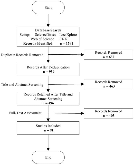
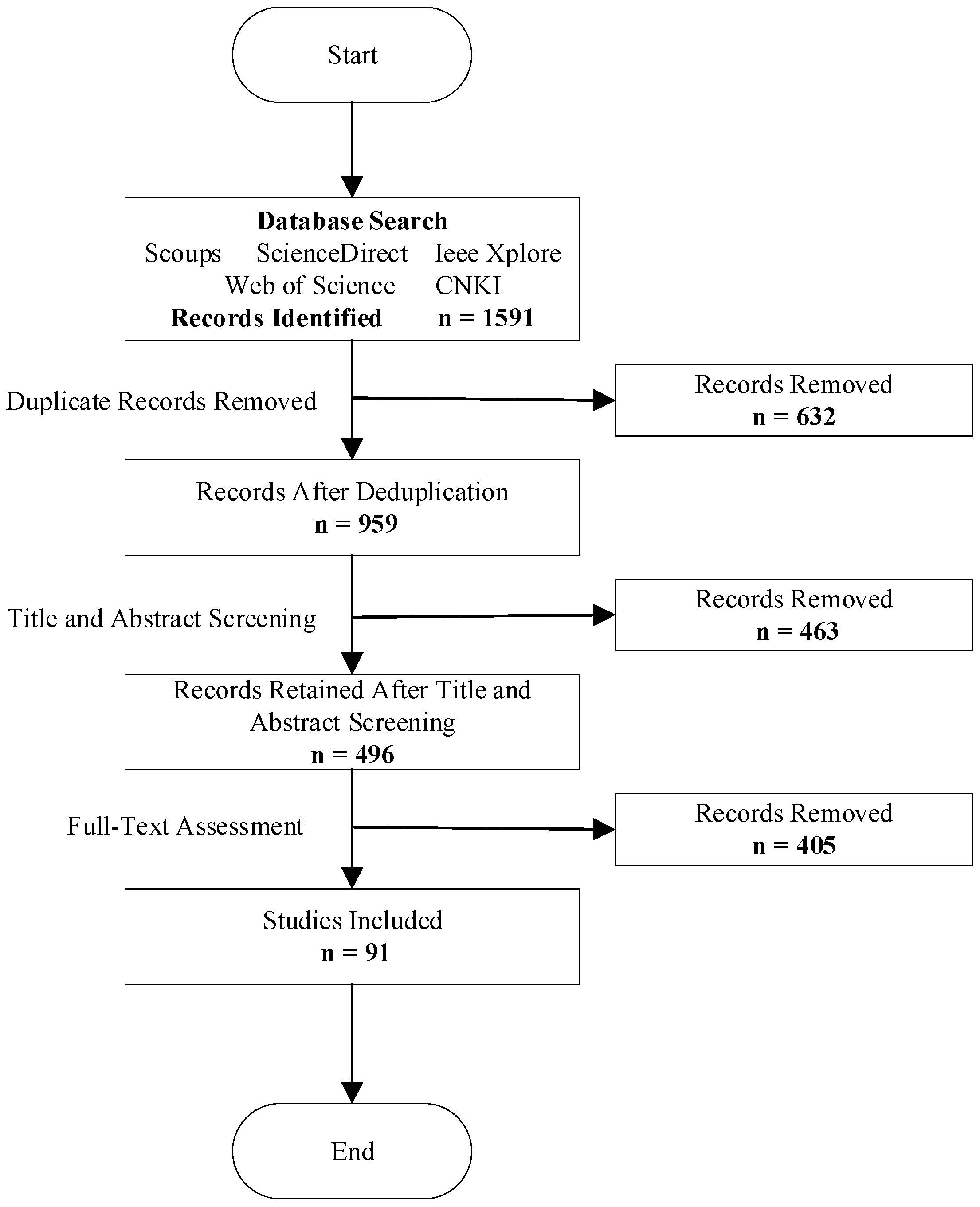
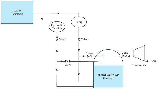
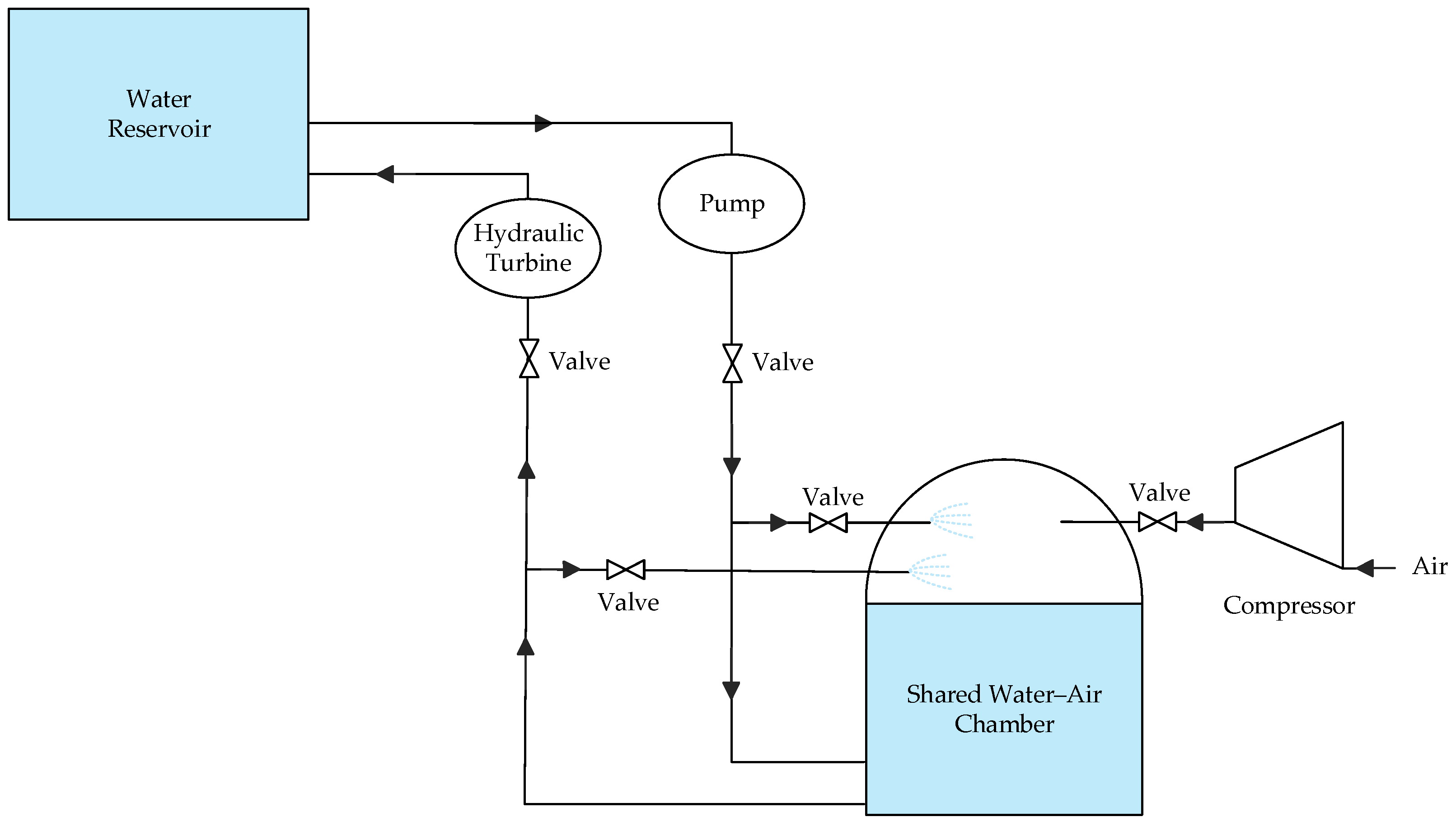
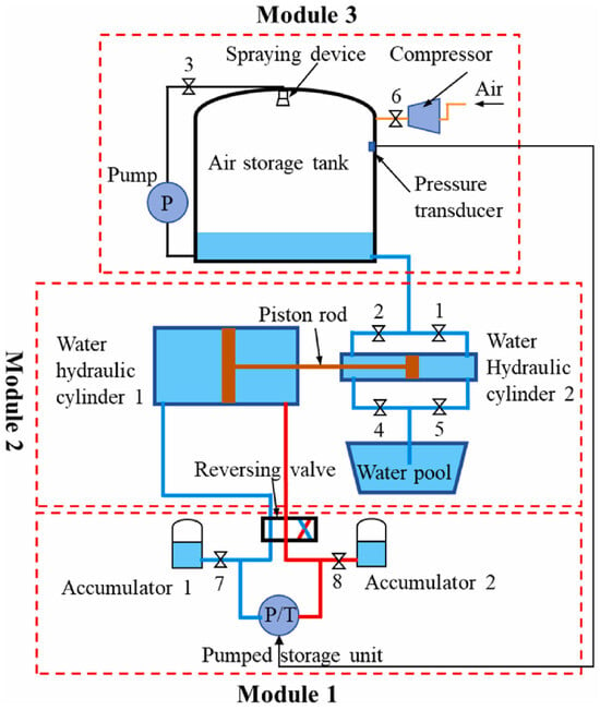
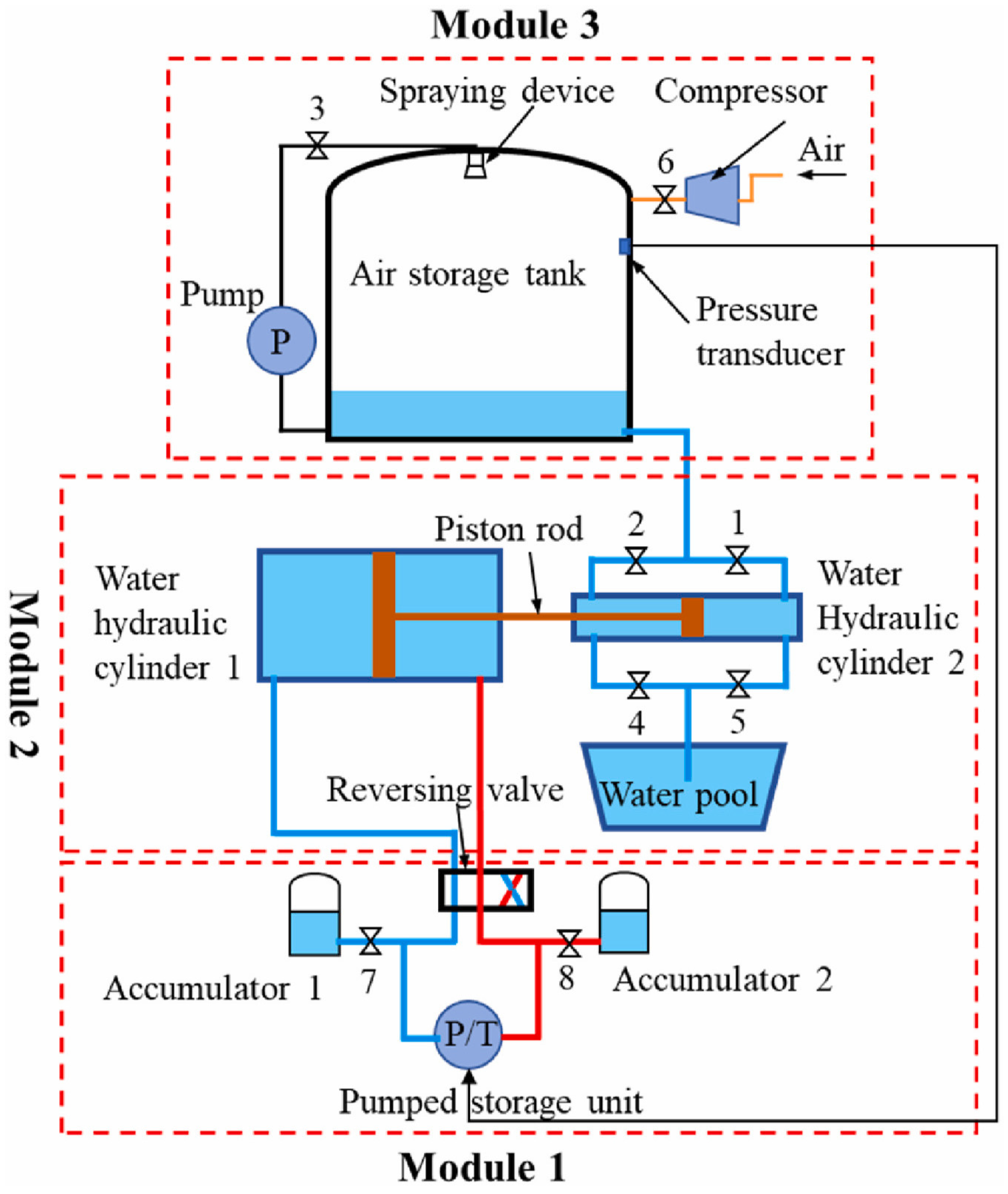
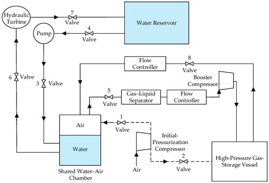
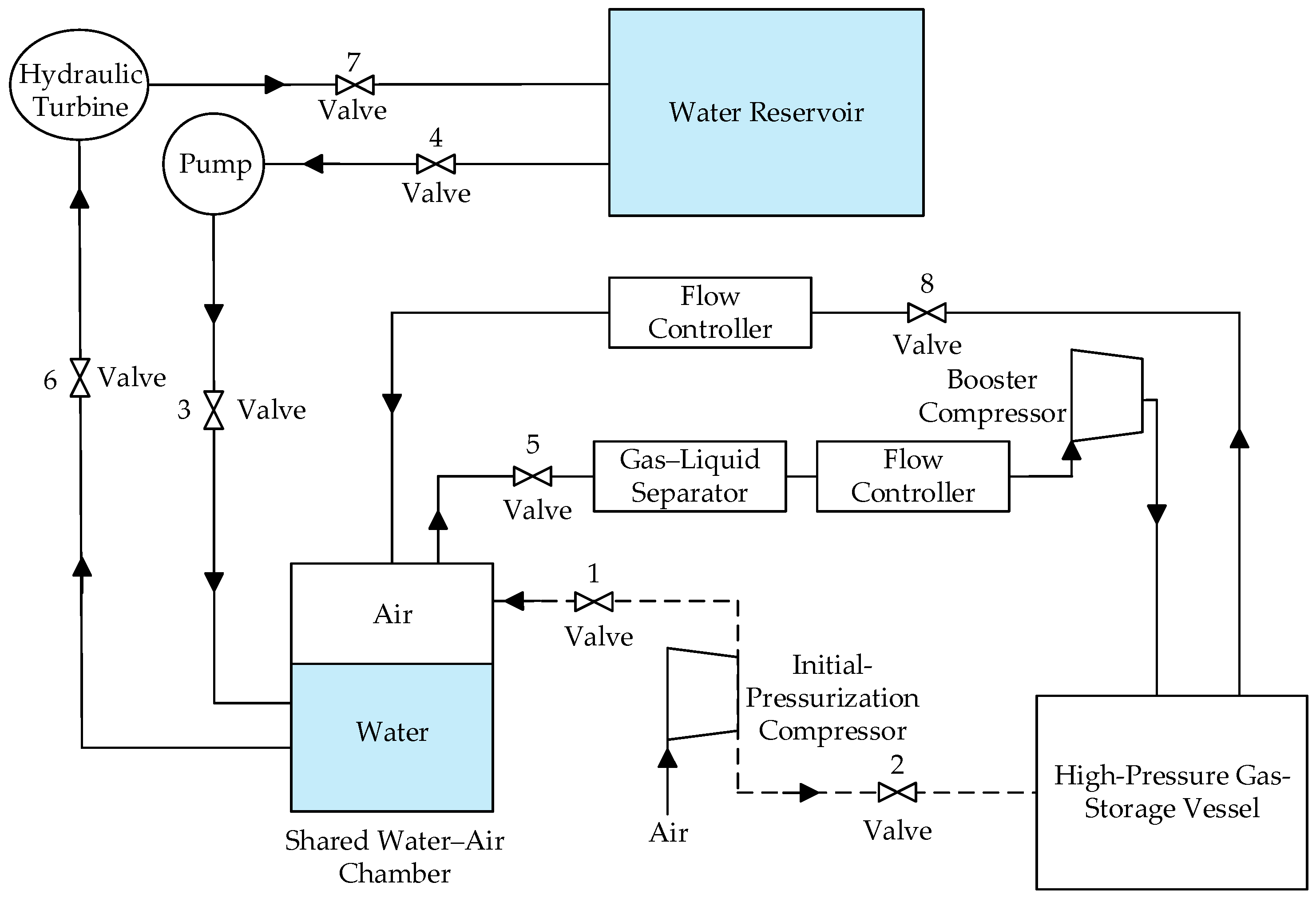
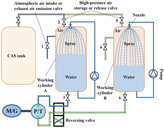
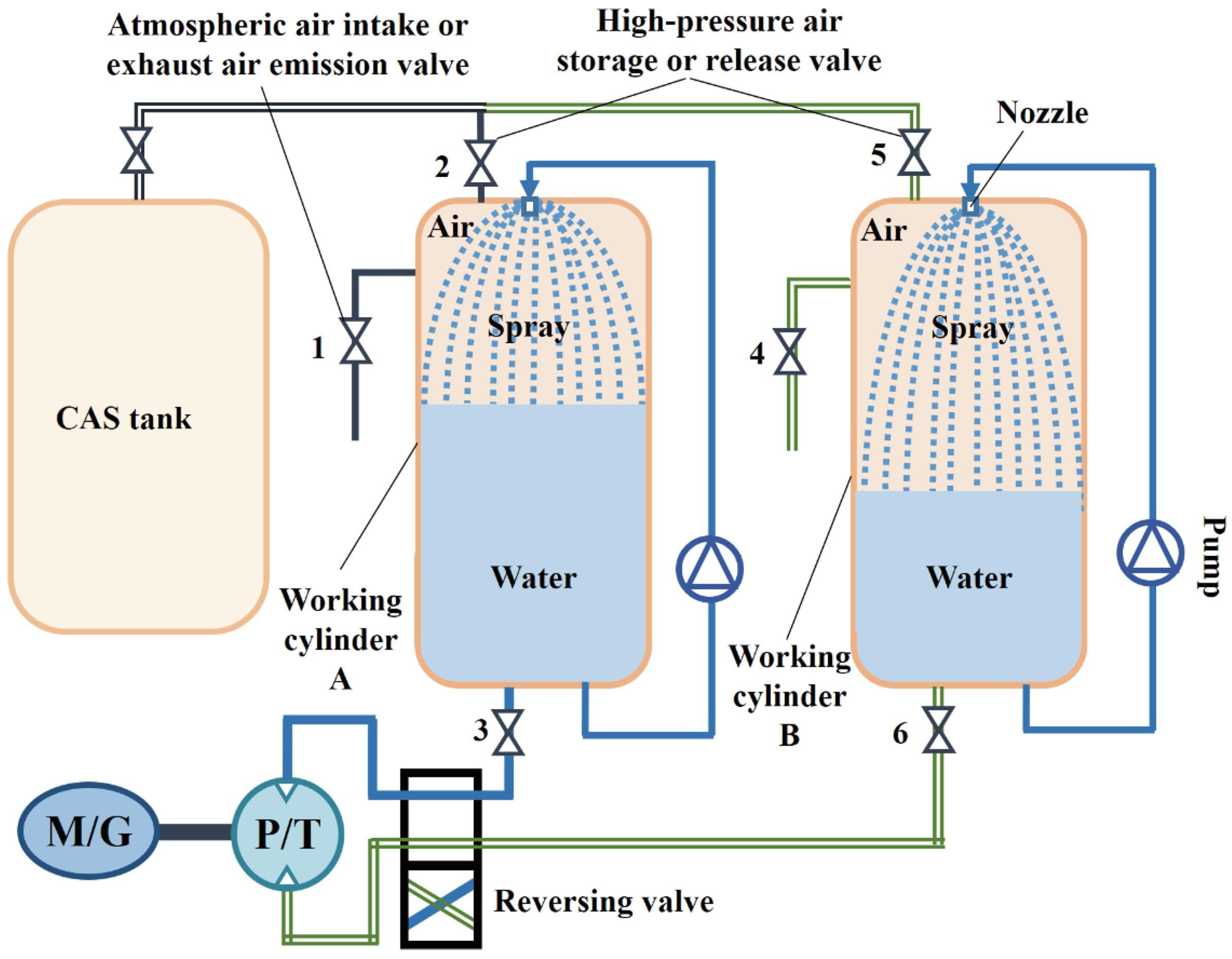
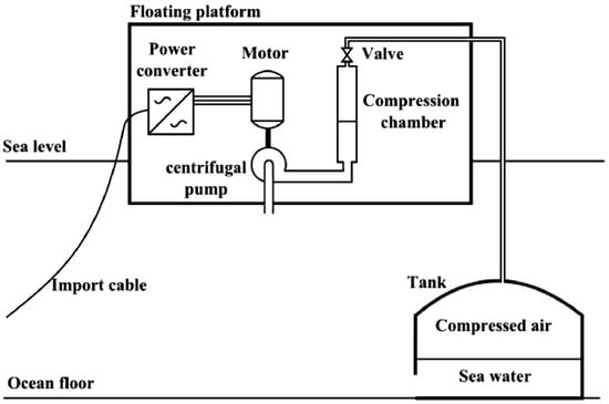

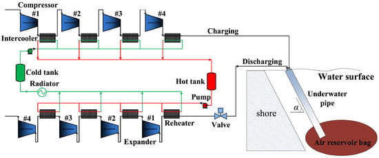
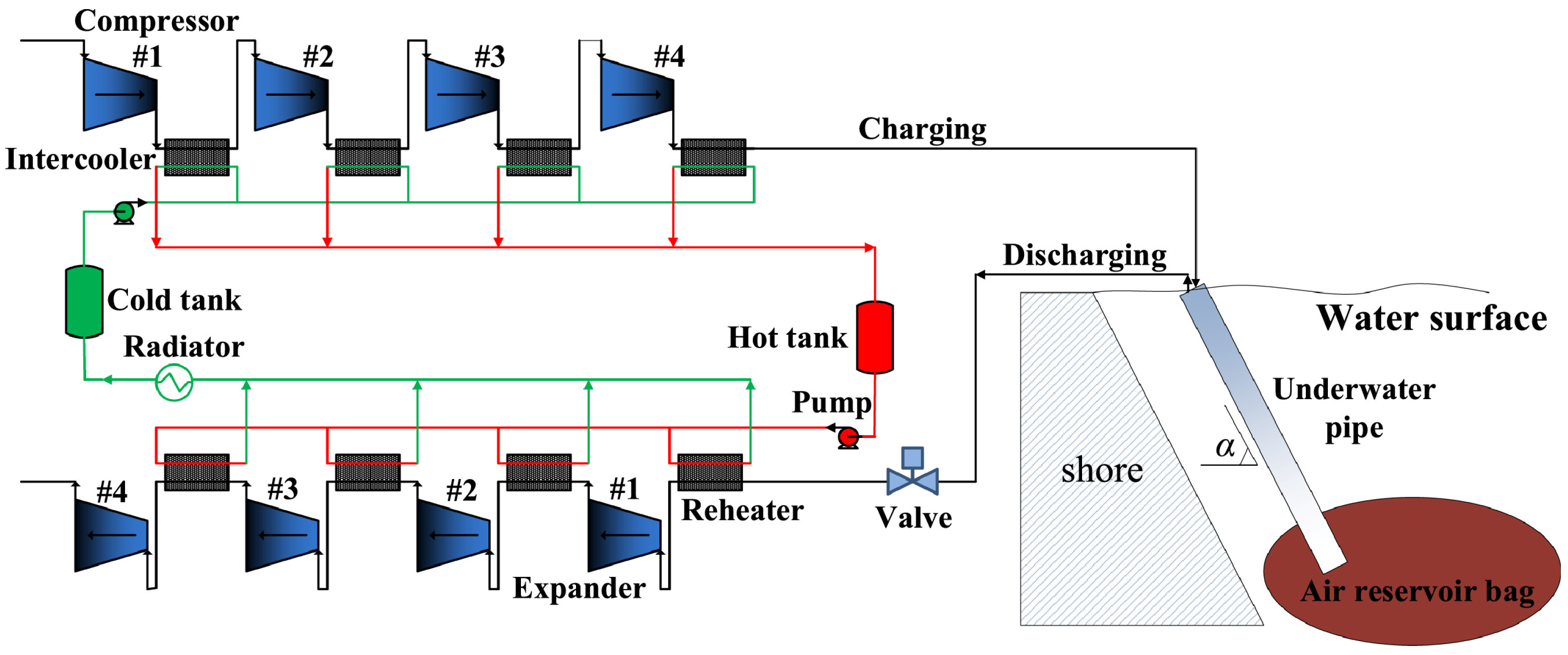
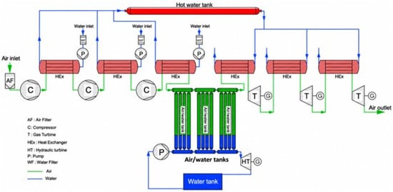
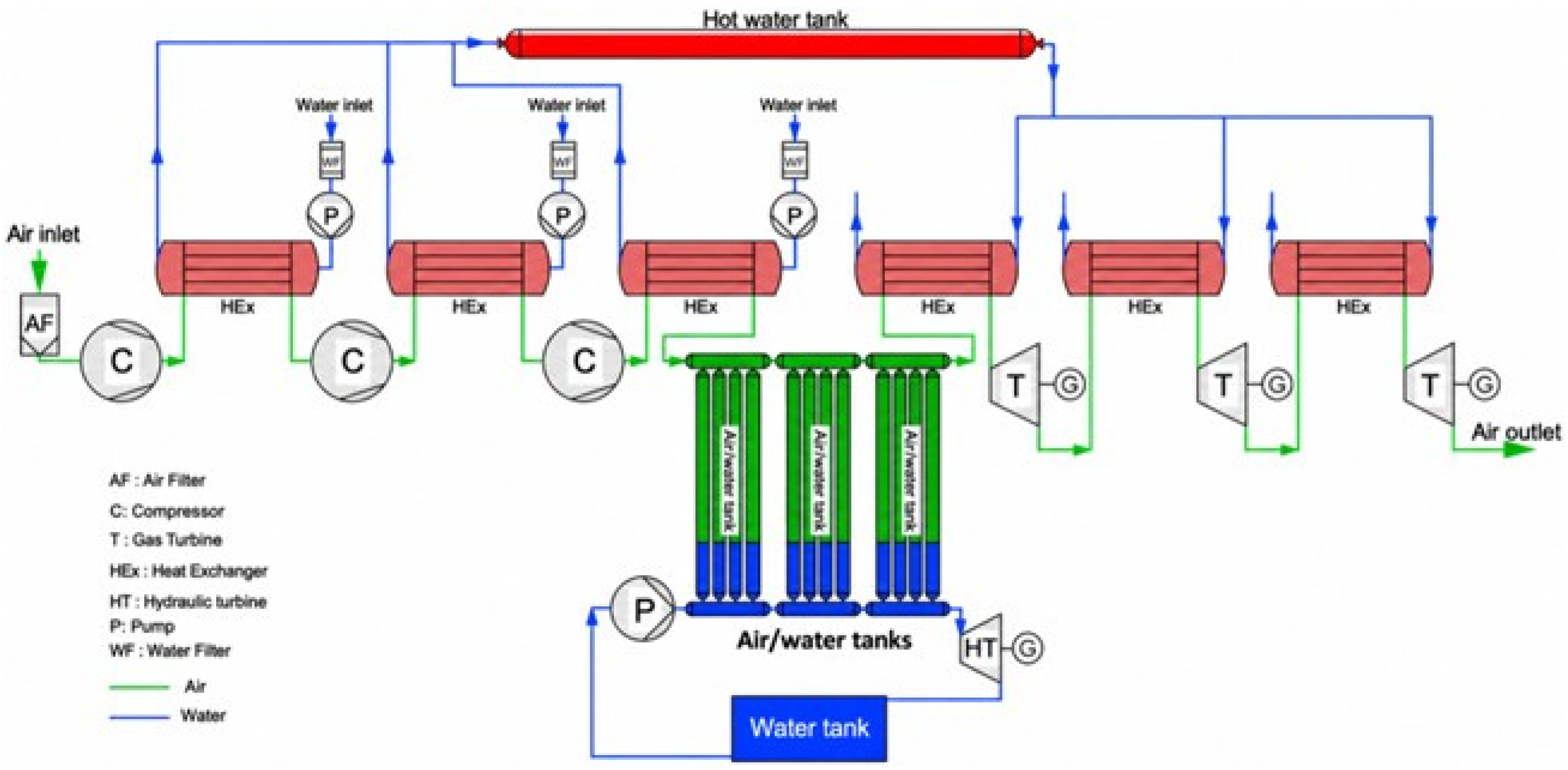
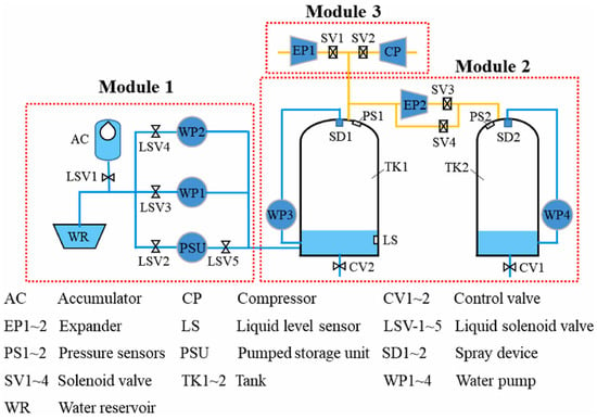
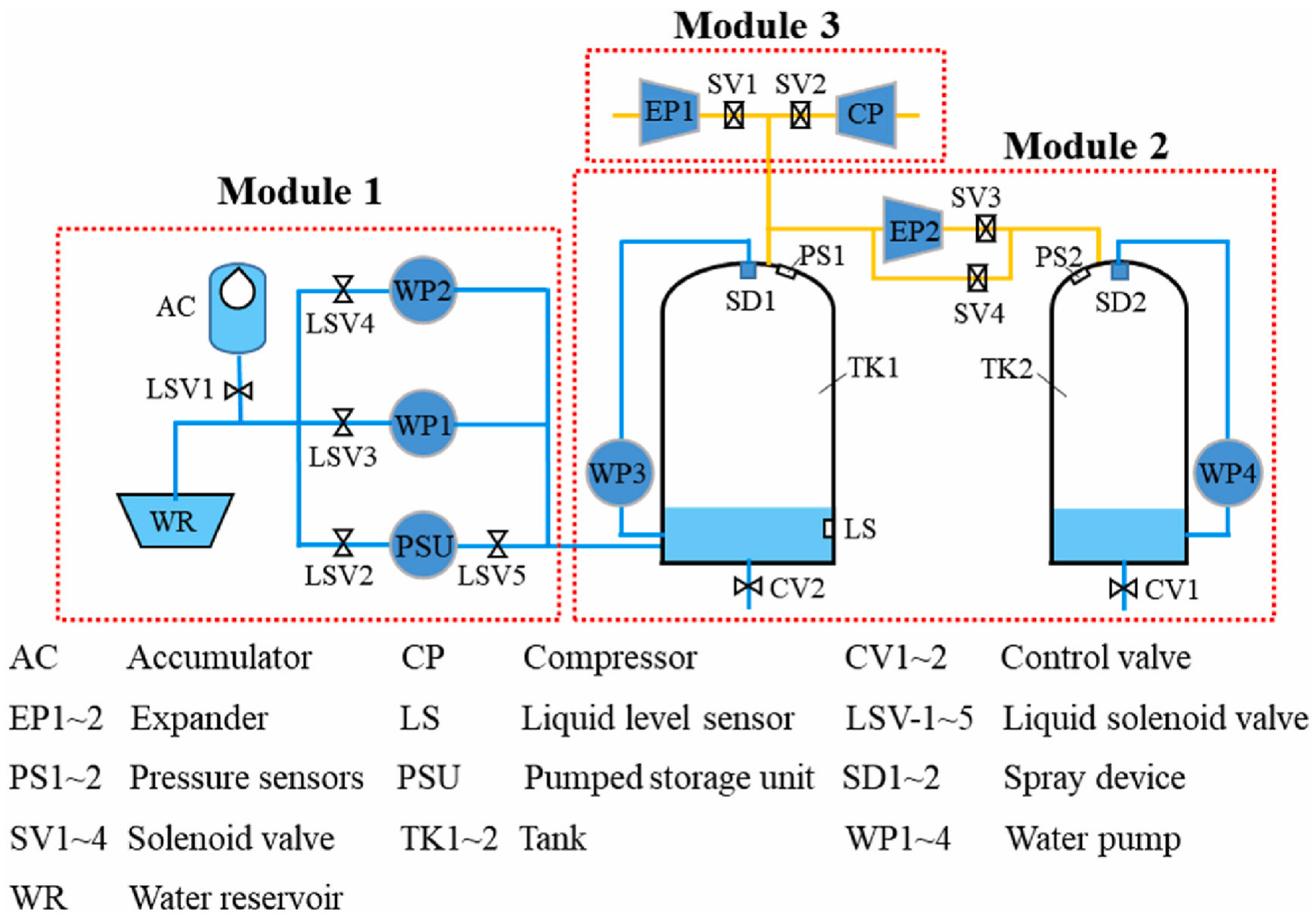
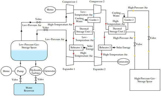
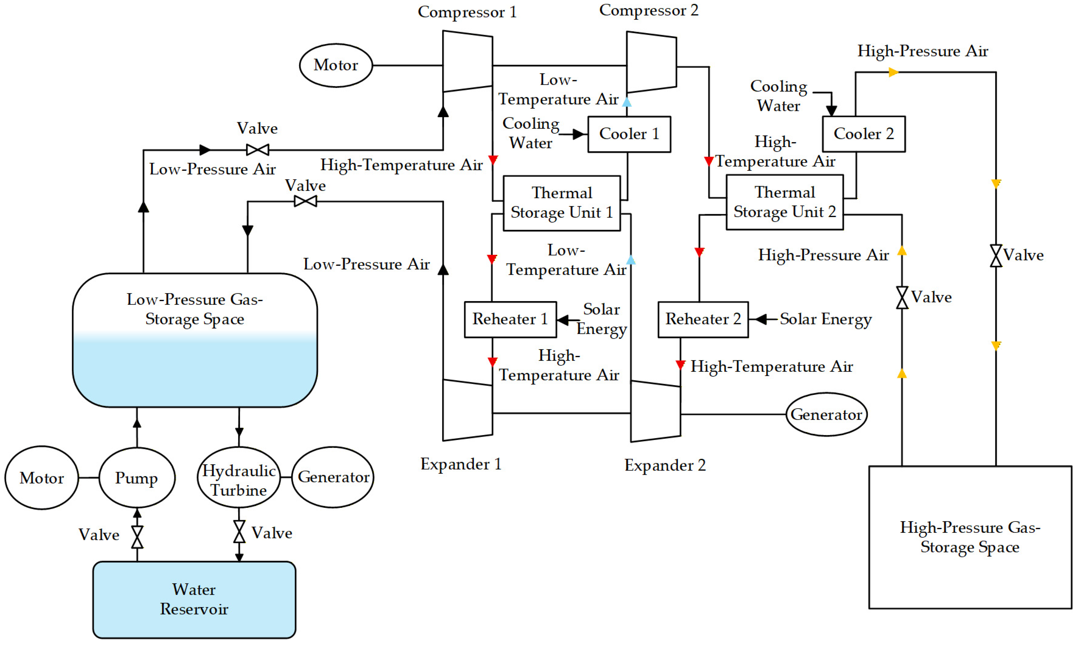
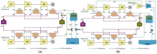
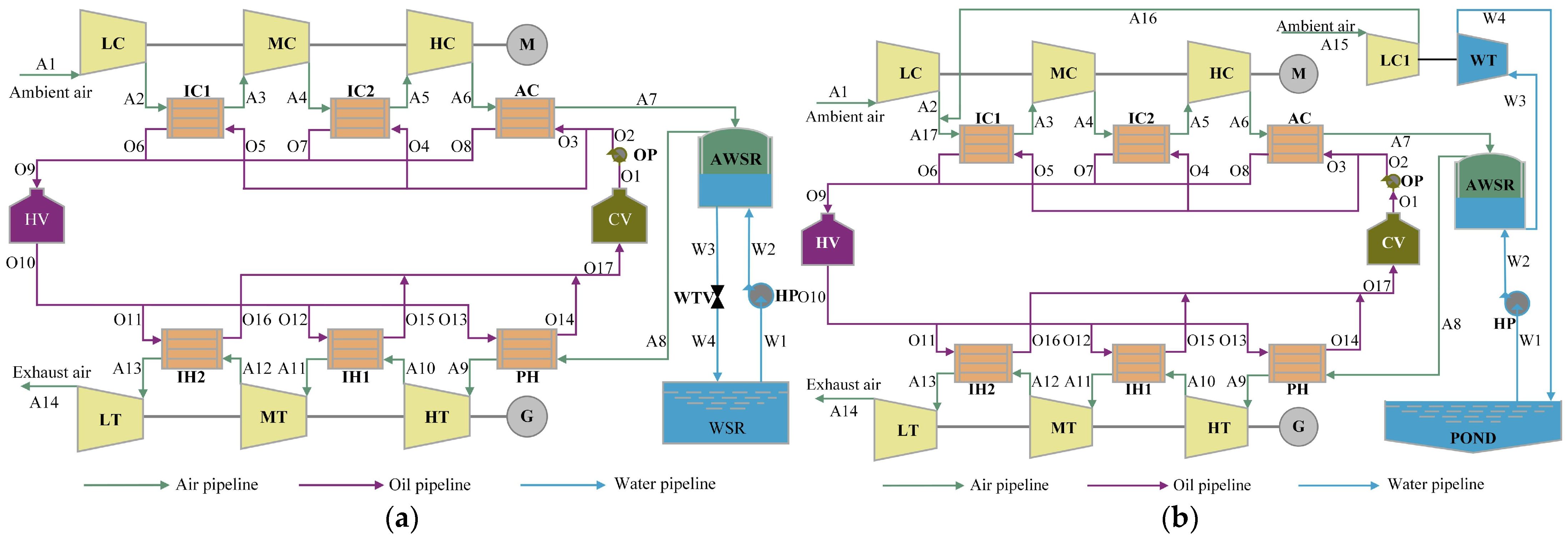

Disclaimer/Publisher’s Note: The statements, opinions and data contained in all publications are solely those of the individual author(s) and contributor(s) and not of MDPI and/or the editor(s). MDPI and/or the editor(s) disclaim responsibility for any injury to people or property resulting from any ideas, methods, instructions or products referred to in the content. |
© 2026 by the authors. Licensee MDPI, Basel, Switzerland. This article is an open access article distributed under the terms and conditions of the Creative Commons Attribution (CC BY) license.