Hydraulically Coupled Compressed-Air Energy Storage Systems: A Review of Configurations and Performance with Emphasis on PHCAES

 ,
, 
Abstract
1. Introduction
2. Development and Classification of Hydraulic-Pneumatic Compressed Air Energy Storage Systems
2.1. Classification and Development of Hydraulic-Pneumatic CAES Systems
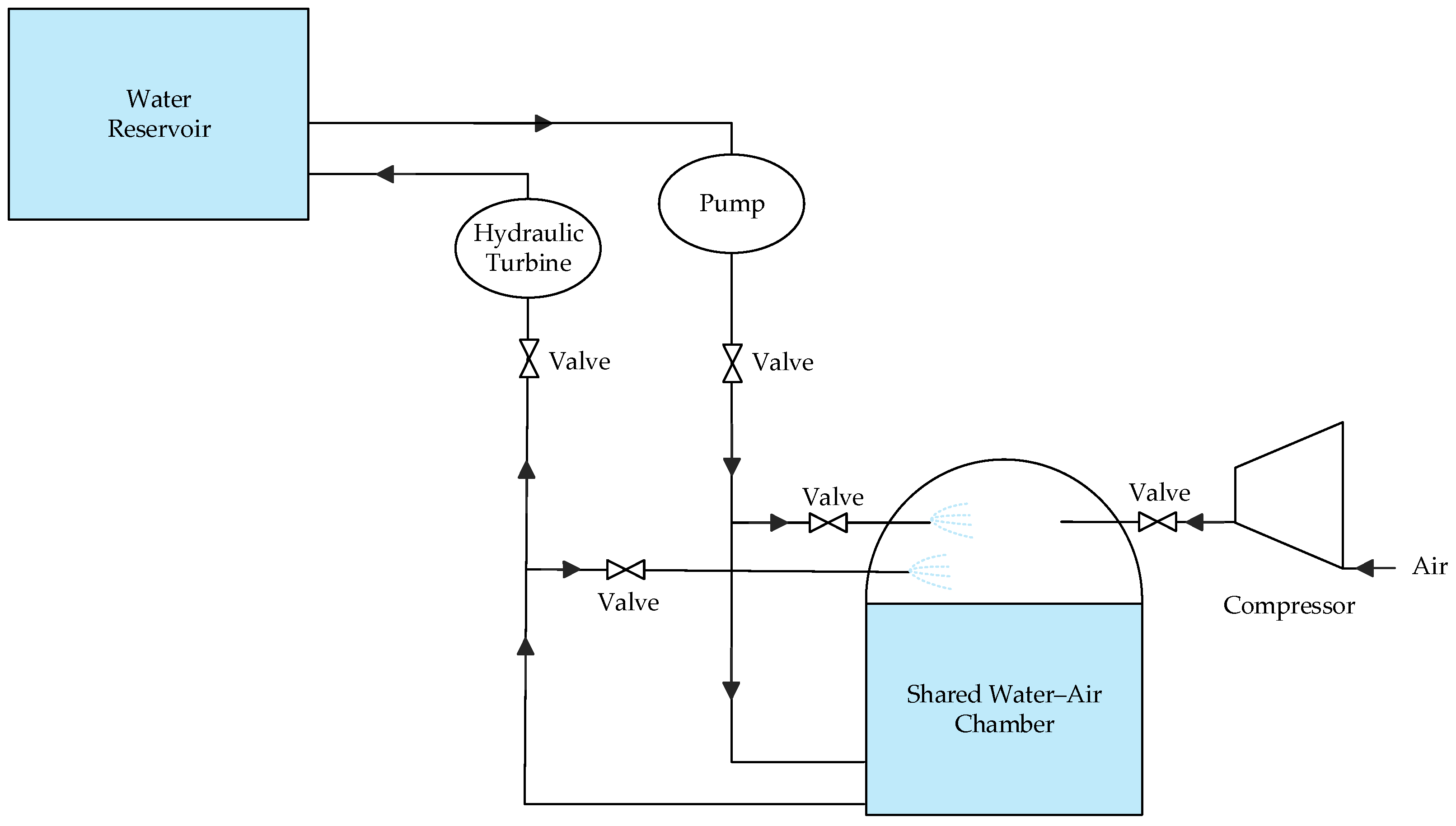
2.1.1. Pumped Hydro Compressed Air Energy Storage Systems
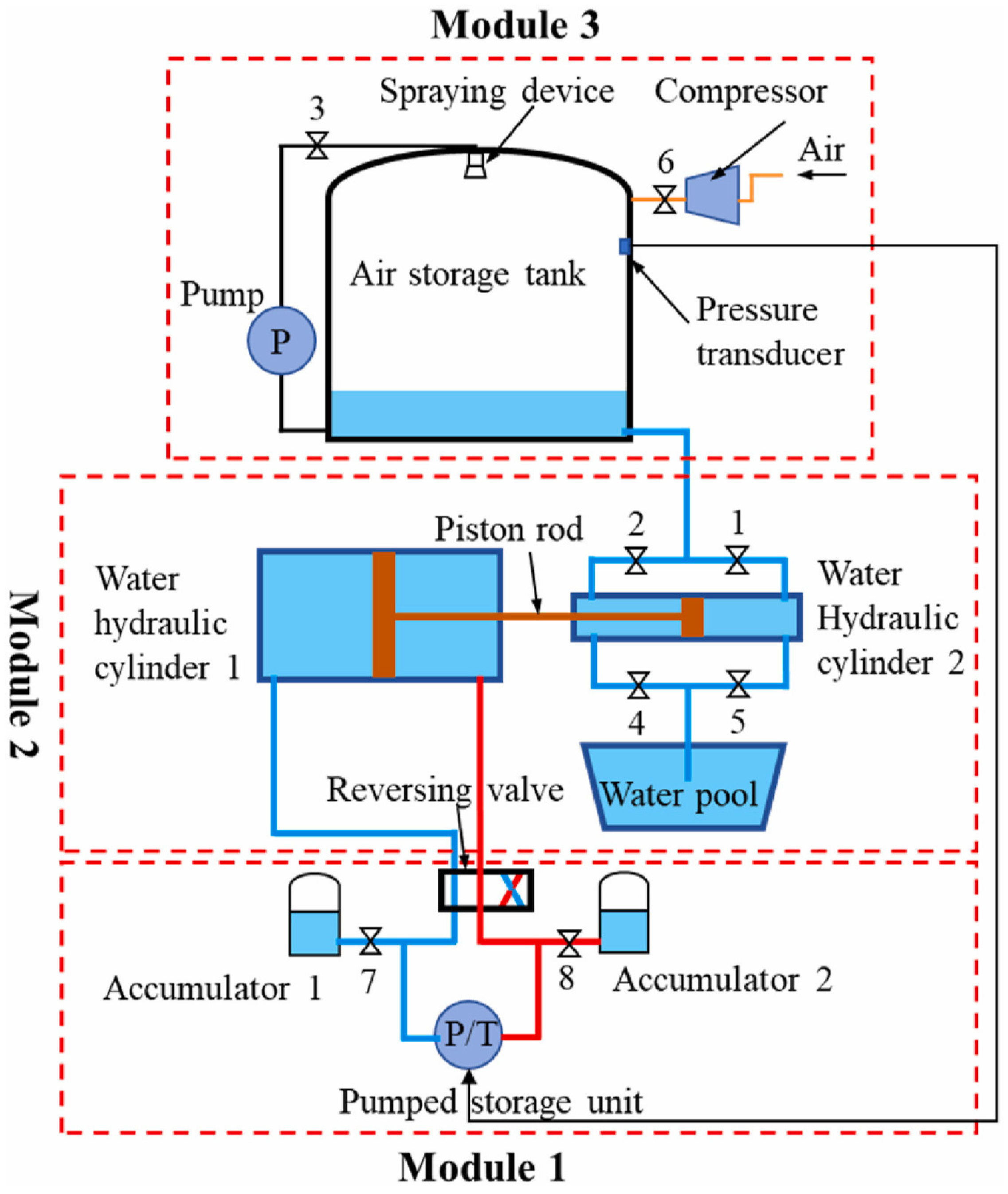
2.1.2. Liquid Piston and Hydro-Pneumatic CAES Systems
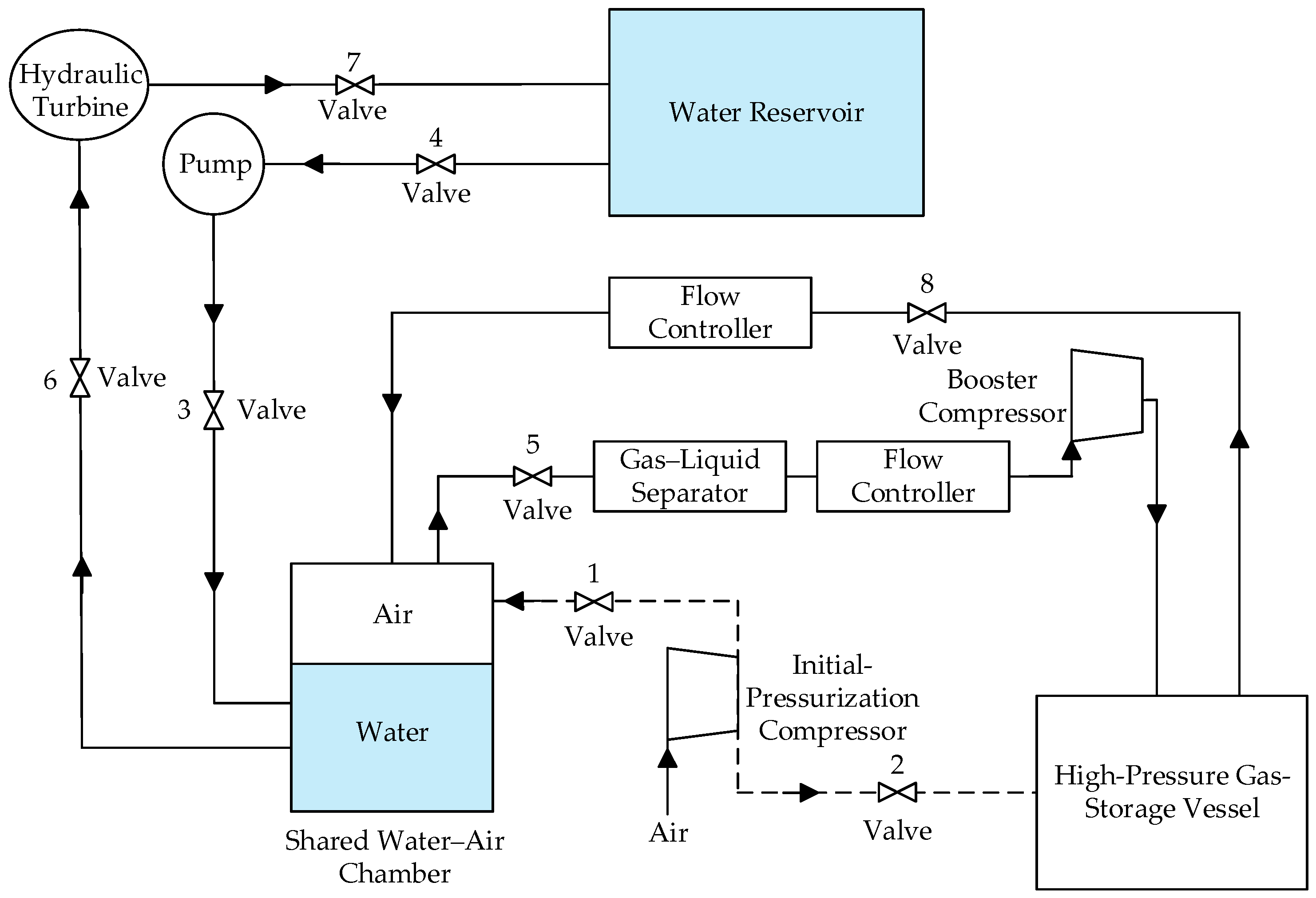
2.1.3. Constant-Pressure Hydraulic-Assisted CAES Systems
2.1.4. Hydraulic–Pneumatic Cascade and Hybrid Energy Storage Systems
2.2. Comparative Analysis of Hydraulic-Pneumatic CAES Systems
3. Performance, Economic and Environmental Assessment of PHCAES
3.1. Assessment Scope and Performance Metrics
3.2. Comparative Performance and Storage Characteristics
3.3. Techno-Economic Comparison
3.4. Environmental Performance and Lifecycle Considerations
4. Performance Mechanisms and Design Trade-Offs in PHCAES Systems
4.1. Pressure-Volume Matching and Storage Utilisation
4.2. Heat-Transfer and Power-Density Trade-Offs
4.3. Machinery Efficiency and Off-Design Operation
4.4. Configuration-Specific Design Priorities
5. Conclusions
5.1. Main Conclusions
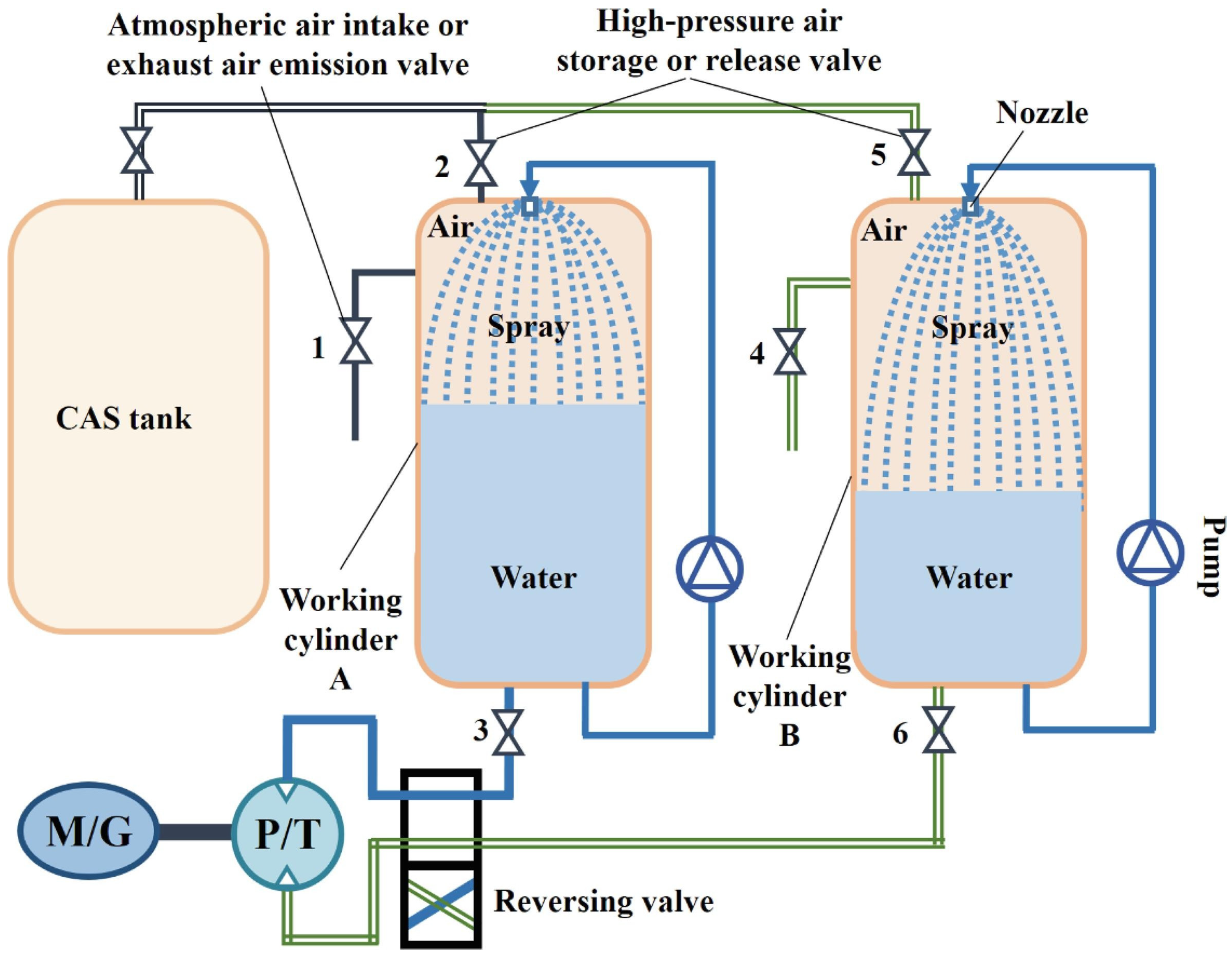
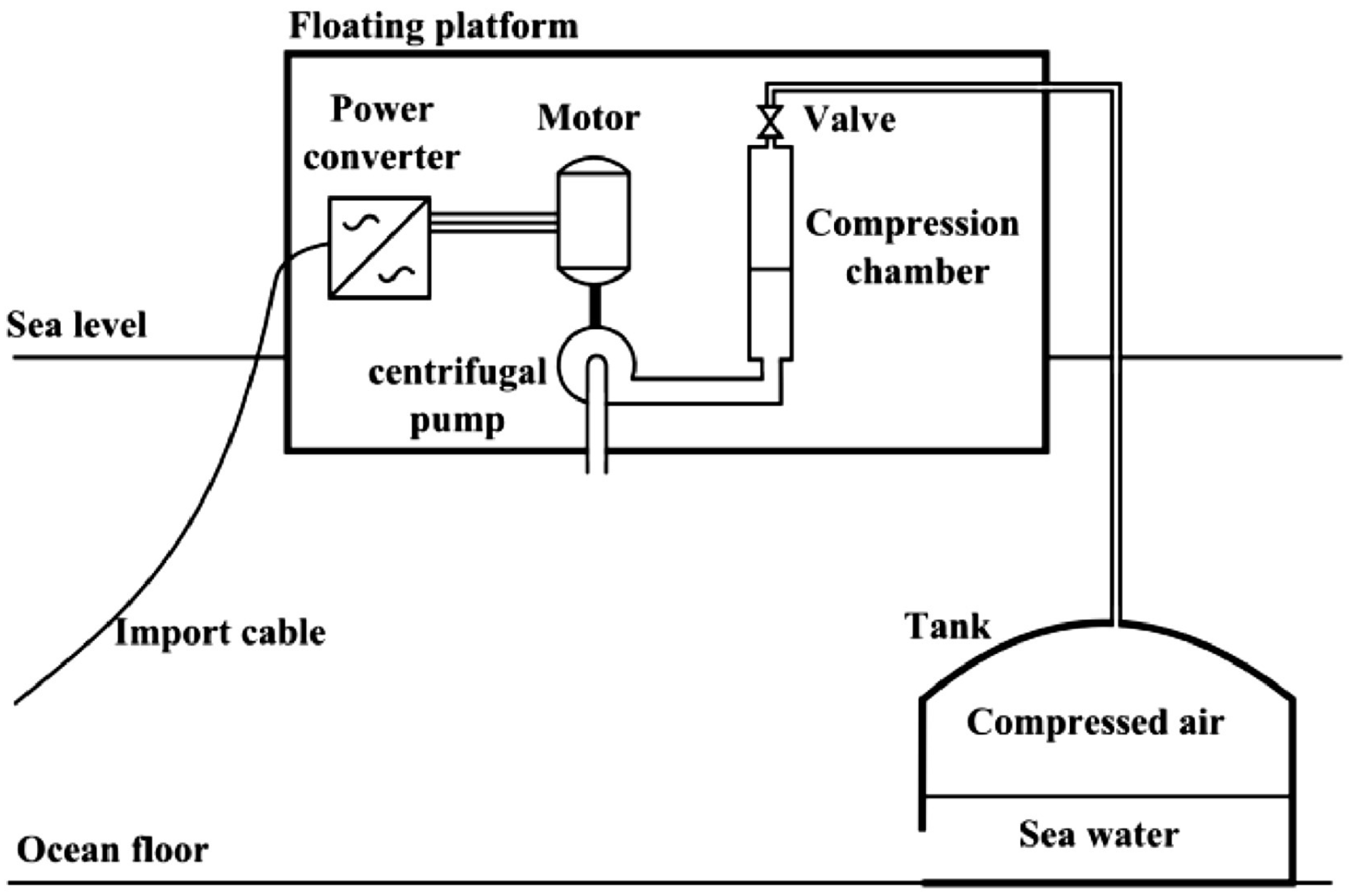
- Hydraulically coupled compressed-air energy storage can be divided into PHCAES, liquid-piston systems, hydraulically compensated constant-pressure CAES, and hydraulic–pneumatic cascade or hybrid systems. In PHCAES, compressed air creates a hydraulic head for pumping and generation; liquid-piston systems emphasise gas compression and expansion through liquid displacement and enhanced gas–liquid heat transfer. Hydraulically compensated CAES uses water to stabilise air-storage pressure while retaining compressors and expanders, whereas cascade or hybrid systems allocate energy conversion across multiple hydraulic and pneumatic stages. Within the PHCAES family, variable- and constant-pressure configurations should be distinguished according to whether the water–air chamber pressure varies during operation.
- The principal advantage of PHCAES over conventional PHES and CAES is conditional rather than universal. Compressed air creates a virtual hydraulic head, allowing hydraulic energy conversion where a large natural elevation difference is unavailable. Direct water-displacement PHCAES can also avoid routine gas compression and expansion after initial pressurisation, thereby simplifying the gas-side conversion pathway and avoiding the fuel combustion associated with diabatic CAES. However, these benefits are obtained by introducing pressurised water–air chambers, variable-head hydraulic operation and, in some configurations, additional receivers and regulation equipment. PHCAES should therefore be regarded as a means of improving siting flexibility and redistributing system complexity, rather than as an inherently more efficient or less costly alternative.
- Reported efficiency depends strongly on the evaluation boundary. The GLIDES experiments combined an indicated efficiency of 94% with an electrical RTE of only 18–24%, while the 100 kW constant-pressure PHCAES prototype achieved a measured electrical RTE of 51%; its 63% value was projected after assuming improved turbine–generator performance. Tank-level and thermodynamic efficiencies therefore cannot be used as substitutes for electrical RTE. Pressure–volume matching, gas–liquid heat transfer, hydraulic-machine performance and auxiliary consumption must be evaluated within the same cycle boundary.
- Performance enhancement involves coupled trade-offs. Increasing flow raises power density but shortens the available heat-transfer time, while spray injection improves thermal behaviour at the cost of pumping power. Constant-pressure regulation narrows the hydraulic operating range but introduces compression and regulation losses. The effectiveness of each measure consequently depends on whether its local benefit survives after auxiliary consumption and off-design losses are included. No single pressure, flow rate or heat-transfer strategy is optimal across all PHCAES configurations and operating scales.
- Current evidence does not establish a general economic or environmental advantage for PHCAES. Its cost is governed largely by the storage structure: aboveground pressure vessels remain expensive, whereas underground caverns or reusable pressure infrastructure may improve competitiveness. PHCAES can avoid the operational fuel emissions of diabatic CAES and may reduce the reservoir and land requirements of conventional PHES, but these potential benefits must be balanced against pressure-vessel materials, cavern construction and auxiliary electricity. The absence of consistent lifecycle assessments prevents a definitive environmental ranking.
5.2. Research Gaps and Future Directions
- Existing studies use inconsistent boundaries for RTE, energy density and storage volume, and frequently mix experimental and projected results. Future experiments should report net electrical input and output, auxiliary and standby consumption, cycle-averaged machinery efficiency and clearly defined storage-volume boundaries. Initial pressurisation should be reported separately from routine cycling, and energy-density calculations should state whether they include only the working chamber or all storage structures.
- Pressure, displacement ratio, flow rate, spray conditions and machinery operation are often optimised independently. Future models should combine gas thermodynamics with measured pump and turbine performance maps and include spray-pump, throttling and pipeline losses. Multi-unit coordination and staged pressure-energy recovery should be assessed using net electrical performance.
- Most evidence remains model-based or limited to small prototypes. Larger and longer-duration demonstrations are required to evaluate pressure-vessel fatigue, sealing, corrosion, gas dissolution, gas–liquid entrainment and cavern stability under repeated cycling. Cost assessments should adopt consistent power, duration, price-year and lifecycle assumptions to determine when underground or reusable pressure infrastructure makes PHCAES competitive.
- Complete lifecycle assessments of variable- and constant-pressure PHCAES remain unavailable. Future studies should quantify construction, auxiliary electricity, maintenance and end-of-life impacts using consistent functional units and charging-electricity scenarios. Multi-timescale planning and operational studies based on realistic system constraints are also needed to establish the contribution of PHCAES to renewable-energy integration, firm power delivery and grid reliability.
Author Contributions
Funding
Data Availability Statement
Conflicts of Interest
References
- Deshmukh, M.K.G.; Sameeroddin, M.; Abdul, D.; Sattar, M.A. Renewable energy in the 21st century: A review. Mater. Today Proc. 2023, 80, 1756–1759. [Google Scholar] [CrossRef] [Scilit]
- Wang, Y.; Wang, R.; Tanaka, K.; Ciais, P.; Penuelas, J.; Balkanski, Y.; Sardans, J.; Hauglustaine, D.; Liu, W.; Xing, X.; et al. Accelerating the energy transition towards photovoltaic and wind in China. Nature 2023, 619, 761–767. [Google Scholar] [CrossRef] [Scilit] [PubMed]
- Lei, K.; Chang, J.; Wang, X.; Guo, A.; Wang, Y.; Ren, C. Peak shaving and short-term economic operation of hydro-wind-PV hybrid system considering the uncertainty of wind and PV power. Renew. Energy 2023, 215, 118903. [Google Scholar] [CrossRef] [Scilit]
- Dunn, B.; Kamath, H.; Tarascon, J.M. Electrical energy storage for the grid: A battery of choices. Science 2011, 334, 928–935. [Google Scholar] [CrossRef] [Scilit] [PubMed]
- Rahman, M.M.; Oni, A.O.; Gemechu, E.; Kumar, A. Assessment of energy storage technologies: A review. Energy Convers. Manag. 2020, 223, 113295. [Google Scholar] [CrossRef] [Scilit]
- Mastoi, M.S.; Wang, D.; Zhou, X.; He, X.; Hassan, M.; Ali, A.; Rehman, A. Study of energy storage technology approaches for mitigating wind power fluctuations to enhance smart grid resilience. Renew. Sustain. Energy Rev. 2025, 224, 116072. [Google Scholar] [CrossRef] [Scilit]
- Zhao, H.; Wu, Q.; Hu, S.; Xu, H.; Rasmussen, C.N. Review of energy storage system for wind power integration support. Appl. Energy 2015, 137, 545–553. [Google Scholar] [CrossRef] [Scilit]
- Mahmoud, M.; Ramadan, M.; Olabi, A.G.; Pullen, K.; Naher, S. A review of mechanical energy storage systems combined with wind and solar applications. Energy Convers. Manag. 2020, 210, 112670. [Google Scholar] [CrossRef] [Scilit]
- Olympios, A.V.; McTigue, J.D.; Farres-Antunez, P.; Tafone, A.; Romagnoli, A.; Li, Y.; Ding, Y.; Steinmann, W.; Wang, L.; Chen, H.; et al. Progress and prospects of thermo-mechanical energy storage—A critical review. Prog. Energy 2021, 3, 022001. [Google Scholar] [CrossRef] [Scilit]
- Yang, Y.; Bremner, S.; Menictas, C.; Kay, M. Battery energy storage system size determination in renewable energy systems: A review. Renew. Sustain. Energy Rev. 2018, 91, 109–125. [Google Scholar] [CrossRef] [Scilit]
- Nyamathulla, S.; Dhanamjayulu, C. A review of battery energy storage systems and advanced battery management system for different applications: Challenges and recommendations. J. Energy Storage 2024, 86, 111179. [Google Scholar] [CrossRef] [Scilit]
- Ali, M.H.; Wu, B.; Dougal, R.A. An overview of SMES applications in power and energy systems. IEEE Trans. Sustain. Energy 2010, 1, 38–47. [Google Scholar] [CrossRef] [Scilit]
- Adetokun, B.B.; Oghorada, O.; Abubakar, S.J.A. Superconducting magnetic energy storage systems: Prospects and challenges for renewable energy applications. J. Energy Storage 2022, 55, 105663. [Google Scholar] [CrossRef] [Scilit]
- Lefebvre, D.; Tezel, F.H. A review of energy storage technologies with a focus on adsorption thermal energy storage processes for heating applications. Renew. Sustain. Energy Rev. 2017, 67, 116–125. [Google Scholar] [CrossRef] [Scilit]
- Koohi-Fayegh, S.; Rosen, M.A. A review of energy storage types, applications and recent developments. J. Energy Storage 2020, 27, 101047. [Google Scholar] [CrossRef] [Scilit]
- Arsad, A.Z.; Hannan, M.A.; Al-Shetwi, A.Q.; Mansur, M.; Muttaqi, K.M.; Dong, Z.Y.; Blaabjerg, F. Hydrogen energy storage integrated hybrid renewable energy systems: A review analysis for future research directions. Int. J. Hydrogen Energy 2022, 47, 17285–17312. [Google Scholar] [CrossRef] [Scilit]
- Zhang, F.; Zhao, P.; Niu, M.; Maddy, J. The survey of key technologies in hydrogen energy storage. Int. J. Hydrogen Energy 2016, 41, 14535–14552. [Google Scholar] [CrossRef] [Scilit]
- Pérez-Díaz, J.I.; Chazarra, M.; García-González, J.; Cavazzini, G.; Stoppato, A. Trends and challenges in the operation of pumped-storage hydropower plants. Renew. Sustain. Energy Rev. 2015, 44, 767–784. [Google Scholar] [CrossRef] [Scilit]
- Kong, Y.; Kong, Z.; Liu, Z.; Wei, C.; Zhang, J.; An, G. Pumped storage power stations in China: The past, the present, and the future. Renew. Sustain. Energy Rev. 2017, 71, 720–731. [Google Scholar] [CrossRef] [Scilit]
- Budt, M.; Wolf, D.; Span, R.; Yan, J. A review on compressed air energy storage: Basic principles, past milestones and recent developments. Appl. Energy 2016, 170, 250–268. [Google Scholar] [CrossRef] [Scilit]
- Lund, H.; Salgi, G. The role of compressed air energy storage (CAES) in future sustainable energy systems. Energy Convers. Manag. 2009, 50, 1172–1179. [Google Scholar] [CrossRef] [Scilit]
- Alvarez, G.E. Operation of pumped storage hydropower plants through optimization for power systems. Energy 2020, 202, 117797. [Google Scholar] [CrossRef] [Scilit]
- Yang, K.; Fu, Q.; Yuan, L.; Liu, Q.; He, X.; Liu, F. Research on development demand and potential of pumped storage power plants combined with abandoned mines in China. J. Energy Storage 2023, 63, 106977. [Google Scholar] [CrossRef] [Scilit]
- Zhao, J.F.; Oh, U.J.; Park, J.C.; Park, E.S.; Im, H.B.; Lee, K.Y.; Choi, J.S. A review of world-wide advanced pumped storage hydropower technologies. IFAC Pap. 2022, 55, 170–174. [Google Scholar] [CrossRef] [Scilit]
- Yang, W.; Yang, J. Advantage of variable-speed pumped storage plants for mitigating wind power variations: Integrated modelling and performance assessment. Appl. Energy 2019, 237, 720–732. [Google Scholar] [CrossRef] [Scilit]
- Chazarra, M.; Pérez-Díaz, J.I.; García-González, J.; Praus, R. Economic viability of pumped-storage power plants participating in the secondary regulation service. Appl. Energy 2018, 216, 224–233. [Google Scholar] [CrossRef] [Scilit]
- Yang, W.; Zhao, Z.; Pérez-Díaz, J.I.; Hunt, J.D.; Vagnoni, E.; Nøland, J.K.; Quaranta, E.; Wang, R.; Li, X.; Cheng, Y. Pumped storage hydropower operation for supporting clean energy systems. Nat. Rev. Clean Technol. 2025, 1, 454–473. [Google Scholar] [CrossRef] [Scilit]
- Gao, R.; Wu, F.; Zou, Q.; Chen, J. Optimal dispatching of wind-PV-mine pumped storage power station: A case study in Lingxin Coal Mine in Ningxia Province, China. Energy 2022, 243, 123061. [Google Scholar] [CrossRef] [Scilit]
- Pradhan, A.; Marence, M.; Franca, M.J. The adoption of Seawater Pump Storage Hydropower Systems increases the share of renewable energy production in Small Island Developing States. Renew. Energy 2021, 177, 448–460. [Google Scholar] [CrossRef] [Scilit]
- Puchta, M.; Bard, J.; Dick, C.; Hau, D.; Krautkremer, B.; Thalemann, F.; Hahn, H. Development and testing of a novel offshore pumped storage concept for storing energy at sea—Stensea. J. Energy Storage 2017, 14, 271–275. [Google Scholar] [CrossRef] [Scilit]
- Wang, J.; Lu, K.; Ma, L.; Wang, J.; Dooner, M.; Miao, S.; Li, J.; Wang, D. Overview of compressed air energy storage and technology development. Energies 2017, 10, 991. [Google Scholar] [CrossRef] [Scilit]
- Roos, P.; Haselbacher, A. Analytical modeling of advanced adiabatic compressed air energy storage: Literature review and new models. Renew. Sustain. Energy Rev. 2022, 163, 112464. [Google Scholar] [CrossRef] [Scilit]
- Rabi, A.M.; Radulovic, J.; Buick, J.M. Comprehensive review of compressed air energy storage (CAES) technologies. Thermo 2023, 3, 104–126. [Google Scholar] [CrossRef] [Scilit]
- Guanwei, J.; Weiqing, X.; Maolin, C.; Yan, S. Micron-sized water spray-cooled quasi-isothermal compression for compressed air energy storage. Exp. Therm. Fluid Sci. 2018, 96, 470–481. [Google Scholar] [CrossRef] [Scilit]
- Morgan, R.; Nelmes, S.; Gibson, E.; Brett, G. Liquid air energy storage–analysis and first results from a pilot scale demonstration plant. Appl. Energy 2015, 137, 845–853. [Google Scholar] [CrossRef] [Scilit]
- Guo, H.; Xu, Y.; Chen, H.; Zhou, X. Thermodynamic characteristics of a novel supercritical compressed air energy storage system. Energy Convers. Manag. 2016, 115, 167–177. [Google Scholar] [CrossRef] [Scilit]
- Cheung, B.C.; Carriveau, R.; Ting, D.S.K. Parameters affecting scalable underwater compressed air energy storage. Appl. Energy 2014, 134, 239–247. [Google Scholar] [CrossRef] [Scilit]
- Wang, H.; Xi, G.; Li, R.; Yao, E.; Sun, Z.; Wang, Z.; Zou, H.; Ling, L.; He, X.; Zhang, Y. A Study on the Combined Pumped-Hydro and Compressed Air Energy Storage System. J. Xi’an Jiaotong Univ. 2024, 58, 710049. [Google Scholar] [CrossRef]
- Yang, B.; Li, D.; Zhang, Y.; Fu, X.; Wang, H.; Gong, R.; Wei, X.; Qin, D. Review of innovative design and application of hydraulic compressed air energy storage technology. J. Energy Storage 2024, 98, 113031. [Google Scholar] [CrossRef] [Scilit]
- Li, R.; Zhang, Y.; Guo, Z.; Wang, H.; Xi, G.; Yin, Y.; Sun, H.; Cai, X.; Sun, X. Liquid-Gas Hybrid Compressed Energy Storage: A Novel High-Efficiency and Low-Cost Compressed Air Energy Storage Technology. J. Xi’an Jiaotong Univ. 2026, 60, 115–127. [Google Scholar] [CrossRef]
- Odukomaiya, A.; Kokou, E.; Hussein, Z.; Abu-Heiba, A.; Graham, S.; Momen, A.M. Near-isothermal-isobaric compressed gas energy storage. J. Energy Storage 2017, 12, 276–287. [Google Scholar] [CrossRef] [Scilit]
- Hou, F.; Wang, H.; Ben, Y.; Fen, L.; Du, C. A New Technology for Large-scale Pumped Compressed Air Energy Storage. Fluid Mach. 2019, 47, 44–47. [Google Scholar] [CrossRef]
- Li, C.; Li, Y.; Zhang, Y.; Yang, Z.; Wang, H. Novel Steam Constant-Pressure Pumped Hydro with Compressed Air Energy Storage System and Thermodynamic Analysis. J. Xi’an Jiaotong Univ. 2021, 55, 84–91. [Google Scholar] [CrossRef]
- Lian Yin, J.; Kim, Y.T.; Lee, Y.H. A hybrid energy storage system using pump compressed air and micro-hydro turbine. Renew. Energy 2014, 65, 117–122. [Google Scholar] [CrossRef] [Scilit]
- Patil, V.C.; Acharya, P.; Ro, P.I. Experimental investigation of water spray injection in liquid piston for near-isothermal compression. Appl. Energy 2020, 259, 114182. [Google Scholar] [CrossRef] [Scilit]
- ILghami, H.; Hadidi, A. Thermodynamic analysis of an energy storage system based on pumped hydro combined with compressed gas for use in a solar powerplant. J. Energy Storage 2021, 33, 102048. [Google Scholar] [CrossRef] [Scilit]
- Zhao, P.; Zhang, S.; Xu, W.; Liu, A.; Wu, W.; Wang, J. Performance analysis of a pumped hydro assisted near-isothermal compressed carbon dioxide energy storage system with gas/liquid phase change process. Int. J. Energy Res. 2022, 46, 13711–13725. [Google Scholar] [CrossRef] [Scilit]
- Gouda, E.M.; Fan, Y.; Benaouicha, M.; Neu, T.; Luo, L. Review on Liquid Piston technology for compressed air energy storage. J. Energy Storage 2021, 43, 103111. [Google Scholar] [CrossRef] [Scilit]
- Hao, F.; Mu, A.; Lv, Z.; Zhou, H. A comprehensive review of liquid piston compressed air energy storage for sustainable renewable energy integration. J. Energy Storage 2024, 98, 113071. [Google Scholar] [CrossRef] [Scilit]
- Wang, H.; Wang, L.; Wang, X.; Yao, E. A novel pumped hydro combined with compressed air energy storage system. Energies 2013, 6, 1554–1567. [Google Scholar] [CrossRef] [Scilit]
- Bi, J.; Jiang, T.; Chen, W.; Ma, X. Research on storage capacity of compressed air pumped hydro energy storage equipment. Energy Power Eng. 2013, 5, 26–30. [Google Scholar] [CrossRef]
- Odukomaiya, A.; Abu-Heiba, A.; Graham, S.; Momen, A.M. Experimental and analytical evaluation of a hydro-pneumatic compressed-air Ground-Level Integrated Diverse Energy Storage (GLIDES) system. Appl. Energy 2018, 221, 75–85. [Google Scholar] [CrossRef] [Scilit]
- Kassaee, S.; Abu-Heiba, A.; Ally, M.R.; Mench, M.M.; Liu, X.; Odukomaiya, A.; Chen, Y.; King, T.J., Jr.; Smith, B.T.; Momen, A.M. PART 1-techno-economic analysis of a grid scale Ground-Level Integrated Diverse Energy Storage (GLIDES) technology. J. Energy Storage 2019, 25, 100792. [Google Scholar] [CrossRef] [Scilit]
- Camargos, T.P.; Pottie, D.L.; Ferreira, R.A.; Maia, T.A.; Porto, M.P. Experimental study of a PH-CAES system: Proof of concept. Energy 2018, 165, 630–638. [Google Scholar] [CrossRef] [Scilit]
- Odukomaiya, A.; Abu-Heiba, A.; Gluesenkamp, K.R.; Abdelaziz, O.; Jackson, R.K.; Daniel, C.; Graham, S.; Momen, A.M. Thermal analysis of near-isothermal compressed gas energy storage system. Appl. Energy 2016, 179, 948–960. [Google Scholar] [CrossRef] [Scilit]
- Mozayeni, H.; Wang, X.; Negnevitsky, M.; Kefayati, G. Study of effect of heat transfer in an air storage vessel on performance of a pumped hydro compressed air energy storage system. Int. J. Heat Mass Transf. 2020, 148, 119119. [Google Scholar] [CrossRef] [Scilit]
- Yang, B.; Li, D.; Fu, X.; Wang, H.; Gong, R. Energy and exergy analysis of a novel pumped hydro compressed air energy storage system. Energy 2024, 294, 130737. [Google Scholar] [CrossRef] [Scilit]
- Yang, B.; Li, D.; Fu, X.; Wang, H.; Gong, R. Parameter impact and sensitivity analysis of a pumped hydro compressed air energy storage system. Appl. Therm. Eng. 2024, 246, 122951. [Google Scholar] [CrossRef] [Scilit]
- Yao, E.; Wang, H.; Liu, L.; Xi, G. A novel constant-pressure pumped hydro combined with compressed air energy storage system. Energies 2014, 8, 154–171. [Google Scholar] [CrossRef] [Scilit]
- Chen, H.; Wang, H.; Li, R.; Sun, H.; Ge, G.; Ling, L. Experimental and analytical investigation of near-isothermal pumped hydro-compressed air energy storage system. Energy 2022, 249, 123607. [Google Scholar] [CrossRef] [Scilit]
- Chen, H.; Wang, H.; Li, R.; Zhang, Y.; He, X. Thermo-dynamic and economic analysis of sa novel near-isothermal pumped hydro compressed air energy storage system. J. Energy Storage 2020, 30, 101487. [Google Scholar] [CrossRef] [Scilit]
- Chen, H.; Peng, Y.H.; Wang, Y.L.; Zhang, J. Thermodynamic analysis of an open type isothermal compressed air energy storage system based on hydraulic pump/turbine and spray cooling. Energy Convers. Manag. 2020, 204, 112293. [Google Scholar] [CrossRef] [Scilit]
- Patil, V.C.; Acharya, P.; Ro, P.I. Experimental investigation of heat transfer in liquid piston compressor. Appl. Therm. Eng. 2019, 146, 169–179. [Google Scholar] [CrossRef] [Scilit]
- Hu, S.; Zhang, X.; Xu, W.; Cai, M.; Xu, Y.; Chen, H. Experimental study of tube-array-based liquid piston air compressor for near-isothermal compressed air energy storage system. Appl. Energy 2024, 373, 123979. [Google Scholar] [CrossRef] [Scilit]
- Patil, V.C.; Ro, P.I. Experimental study of heat transfer enhancement in liquid piston compressor using aqueous foam. Appl. Therm. Eng. 2020, 164, 114441. [Google Scholar] [CrossRef] [Scilit]
- Ahn, B.; Ro, P.I. Spray cooling technique in liquid piston gas compression and impact of air dissolution on efficiency evaluation at different pressure levels. J. Energy Storage 2024, 81, 110460. [Google Scholar] [CrossRef] [Scilit]
- Neu, T.; Solliec, C.; dos Santos Piccoli, B. Experimental study of convective heat transfer during liquid piston compressions applied to near isothermal underwater compressed-air energy storage. J. Energy Storage 2020, 32, 101827. [Google Scholar] [CrossRef] [Scilit]
- Guo, H.; Xu, Y.; Zhu, Y.; Zhang, X.; Yin, Z.; Chen, H. Coupling properties of thermodynamics and economics of underwater compressed air energy storage systems with flexible heat exchanger model. J. Energy Storage 2021, 43, 103198. [Google Scholar] [CrossRef] [Scilit]
- Kim, Y.M.; Shin, D.G.; Favrat, D. Operating characteristics of constant-pressure compressed air energy storage (CAES) system combined with pumped hydro storage based on energy and exergy analysis. Energy 2011, 36, 6220–6233. [Google Scholar] [CrossRef] [Scilit]
- Mazloum, Y. Exergoeconomic analysis and optimization of a novel isobaric adiabatic compressed air energy storage system. Int. J. Thermodyn. 2017, 20, 6–14. [Google Scholar] [CrossRef] [Scilit]
- Mazloum, Y.; Sayah, H.; Nemer, M. Dynamic modeling and simulation of an isobaric adiabatic compressed air energy storage (IA-CAES) system. J. Energy Storage 2017, 11, 178–190. [Google Scholar] [CrossRef] [Scilit]
- Barbour, E.; Oliveira, M.M., Jr.; Cardenas, B.; Pottie, D. Exergy analysis of isochoric and isobaric adiabatic compressed air energy storage. IET Renew. Power Gener. 2025, 19, e13184. [Google Scholar] [CrossRef] [Scilit]
- Wang, Z.; Xiong, W.; Ting, D.S.K.; Carriveau, R.; Wang, Z. Comparison of underwater and underground CAES systems for integrating floating offshore wind farms. J. Energy Storage 2017, 14, 276–282. [Google Scholar] [CrossRef] [Scilit]
- Liu, C.; Su, X.; Yin, Z.; Sheng, Y.; Zhou, X.; Xu, Y.; Wang, X.; Chen, H. Experimental study on the feasibility of isobaric compressed air energy storage as wind power side energy storage. Appl. Energy 2024, 364, 123129. [Google Scholar] [CrossRef] [Scilit]
- Yang, B.; Li, D.; Wang, C.; Zhang, Y.; Fu, X.; Wang, H. Performance analysis of a novel multi-machine compensable pumped hydro compressed air energy storage system. Energy 2024, 310, 133180. [Google Scholar] [CrossRef] [Scilit]
- Yang, B.; Li, D.; Yang, Q.; Fu, X.; Wang, H.; Gong, R. Spray enhanced heat transfer in multi-machine compensable pumped hydro compressed air energy storage system. Energy 2025, 335, 137848. [Google Scholar] [CrossRef] [Scilit]
- Yao, E.; Xi, G.; Wang, H.; Zou, H.; Li, R.; Hu, Y.; Wang, Z.; Sun, Z. Thermodynamic Analysis on a Novel Compressed-Air Based Pumped Hydro Energy Storage System. J. Xi’an Jiaotong Univ. 2018, 52, 12–18. [Google Scholar] [CrossRef]
- Li, C.; He, X.; Tao, F.; Wang, H. A New Energy Storage System Coupled with Compressed Air and Pumped-Hydro Energy Storage and Related Thermodynamic Analysis. J. Xi’an Jiaotong Univ. 2022, 56, 40–49+71. [Google Scholar] [CrossRef]
- Tao, R.; Hu, X.; Yao, E.; Li, R.; Wang, H.; Chen, H.; Cheng, Z.; Wang, Y. Thermo-Economic Assessments of a Novel IntergratedCompresses Air Energy Storage System. J. Xi’an Jiaotong Univ. 2023, 57, 23–34. [Google Scholar] [CrossRef]
- Chen, H.; Wang, H.; Li, R.; Sun, H.; Zhang, Y.; Ling, L. Thermo-dynamic and economic analysis of a novel pumped hydro-compressed air energy storage system combined with compressed air energy storage system as a spray system. Energy 2023, 280, 128134. [Google Scholar] [CrossRef] [Scilit]
- Cao, R.; Li, W.; Wang, S.; Yang, H.; Kuang, C. Comprehensive comparative study of two novel isobaric adiabatic compressed air energy storage systems coupled with pumped hydro storage. Appl. Therm. Eng. 2024, 257, 124318. [Google Scholar] [CrossRef] [Scilit]
- Mongird, K.; Viswanathan, V.; Alam, J.; Vartanian, C.; Sprenkle, V.; Baxter, R. 2020 grid energy storage technology cost and performance assessment. Energy 2020, 2020, 6–15. [Google Scholar]
- World’s Largest Compressed Air Energy Storage Power Station Launched. Available online: https://english.cas.cn/special-reports/Highlights_2024/202512/t20251219_1138402.shtml (accessed on 14 September 2026).
- Oliveira, L.; Messagie, M.; Mertens, J.; Laget, H.; Coosemans, T.; Van Mierlo, J. Environmental performance of electricity storage systems for grid applications, a life cycle approach. Energy Convers. Manag. 2015, 101, 326–335. [Google Scholar] [CrossRef] [Scilit]
- Simon, T.R.; Inman, D.; Hanes, R.; Avery, G.; Hettinger, D.; Heath, G. Life cycle assessment of closed-loop pumped storage hydropower in the United States. Environ. Sci. Technol. 2023, 57, 12251. [Google Scholar] [CrossRef] [Scilit] [PubMed]
- Mozayeni, H.; Wang, X.; Negnevitsky, M. Thermodynamic and exergy analysis of a combined pumped hydro and compressed air energy storage system. Sustain. Cities Soc. 2019, 48, 101527. [Google Scholar] [CrossRef] [Scilit]
- Bi, X.; Liu, P.; Li, Z. Thermo-dynamic analysis and simulation of a combined air and hydro energy storage (CAHES) system. Energy 2016, 116, 1385–1396. [Google Scholar] [CrossRef] [Scilit]
- Bao, W.; Feng, C.; Cai, W.; Wang, C.; Yang, D.; Tang, L. Parameter Configuration Analysis of Storage Tank in Pumped Hydro Combined with Compressed Air Energy Storage System. China Rural Water Hydropower 2024, 222–227. [Google Scholar] [CrossRef]
- Chen, H.; Cheng, W.L.; Nian, Y.L. Liquid-gas heat transfer characteristics of near isothermal compressed air energy storage based on Spray Injection. Int. J. Heat Mass Transf. 2023, 215, 124530. [Google Scholar] [CrossRef] [Scilit]
- Pottie, D.L.; Ferreira, R.A.; Maia, T.A.; Porto, M.P. An alternative sequence of operation for pumped-hydro compressed air energy storage (PH-CAES) systems. Energy 2020, 191, 116472. [Google Scholar] [CrossRef] [Scilit]
- Srivastava, H.V.; Narayan, L.; Singh, S.K.; Sikarwar, V.S.; Kumar, L.; Kacker, R. Effect of twisted tapes with multiple rotating turbulators on the performance of a double-pipe heat exchanger. Proc. Inst. Mech. Eng. Part E J. Process Mech. Eng. 2025, 09544089251338384. [Google Scholar] [CrossRef] [Scilit]
- Rahman, M.A.; Hasnain, S.M. Enhancing heat exchanger performance with perforated/non-perforated flow modulators generating continuous/discontinuous swirl flow: A comprehensive review. Heat Transf. 2024, 53, 4364–4393. [Google Scholar] [CrossRef] [Scilit]



| Review | Primary Scope | Main Contribution | Difference from the Present Review |
|---|---|---|---|
| [48] | Liquid-piston CAES | Fluid-flow and heat-transfer mechanisms, enhancement methods and empirical correlations | The broader hydraulic-coupling taxonomy and comparisons with PHES and CAES were not primary objectives |
| [49] | Six hydraulic compressed-air energy storage systems | Operating principles, system designs, applications and technical bottlenecks | Reconciliation of quantitative evidence boundaries and focused comparison of variable- and constant-pressure PHCAES were not primary objectives |
| [39] | Liquid-piston CAES | Near-isothermal mechanisms, enhancement approaches, integrated applications and commercialisation prospects | Direct PHCAES configurations and system-level economic and environmental comparisons were outside its main focus |
| Present review | Four hydraulically coupled CAES families, with PHCAES as the central focus | Function-based taxonomy, critical quantitative synthesis, cross-technology comparison and configuration-specific design priorities | Distinguishes evidence types and efficiency boundaries, and identifies the conditions under which PHCAES may offer advantages over PHES and CAES |
| Study | Evidence | System/Feature | Parameters/Conditions | Findings | Limitations |
|---|---|---|---|---|---|
| [50,51] | Model | Foundational direct water-displacement PHCAES | Precharge pressure; vessel volume and rating; gas/water volume allocation; isothermal and adiabatic bounds | Air pressure creates an equivalent hydraulic head; precharge pressure and volume allocation jointly determine recoverable energy and vessel utilisation | Foundational models; the capacity and hydraulic-head results are not measured electrical RTE |
| [52,55] | Experiment + model | Air-based GLIDES: thermal model and prototype | Model: 12 h standby, spray at 12 L/min and optional 70 °C heat. Prototype: four tests over 70–130 bar with 0–352 min standby | Model electrical ratio: 66% baseline, 70% with spray and 78% with waste heat. Prototype electrical RTE: 18–24%; at 70–130 bar, 21% electrical versus 94% indicated efficiency | The model and prototype use different conditions; the tests expose substantial hydraulic and electrical losses despite high indicated efficiency |
| [56] | Model | PHCAES vessel with thermal-transfer analysis | Cylindrical vessel; initial pressure and water inlet/outlet flow varied | Polytropic exponents of approximately 1.05–1.30; higher flow rates weakened near-isothermal behaviour | Vessel-scale thermal evidence; heat-transfer gains must be weighed against power density and cycle duration |
| [57] | Model | Hydraulic potential-energy transfer PHCAES | Approximately 1.6 MPa air-pressure excursion; pump and turbine efficiencies assumed as 90% | Head excursions of 58.5 m during pumping and 48.2 m during generation; calculated electrical efficiency of 59.0% in the first cycle and 62.5% averaged over ten cycles | Head-range reduction was demonstrated in the model, but fixed machinery efficiencies do not quantify the gain from improved operating points; piston friction and leakage remain |
| [59,60] | Model + experiment | Constant-pressure PHCAES | Separate high-pressure air storage regulates the water–air working chamber; Chen et al. used a 100 kW prototype | Measured electrical RTE 51% and energy density 0.33 kWh m−3; a 63% RTE resulted only after assuming 90% turbine–generator efficiency | The arrangement stabilises pump and turbine head but adds compression, throttling and equipment losses; the projected 63% is not a measured improvement |
| [61] | Model | Open-cycle liquid-piston CAES | Alternating working cylinders; separate air reservoir; spray flow up to 10 L/min | Compression/expansion time ratios of 99.2%/95.6%; indicated efficiency up to 98% and electrical RTE up to 76% | Time ratios describe equipment utilisation, not efficiency; high efficiency is predicted under idealised flow and spray assumptions |
| [66] | Experiment + model | Spray-cooled liquid-piston compression | Initial pressures of 1–3 bar; pressure ratio of 2; spray and non-spray cases | Isothermal compression efficiency of 98–98.5% with spray versus 83–88% without; including spray work reversed the advantage in the tested cases | Auxiliary-aware compression analysis, not measured full-cycle RTE; dissolution correction and assumed expansion require validation |
| [67] | Experiment + model | REMORA-related liquid-piston compression | Large elongated compression chambers; piston position and convective heat exchange evaluated | Two successive convection regimes were identified, and correlations were developed and checked against experiments | Component-level thermal validation; no measured RTE of a complete offshore REMORA installation is established |
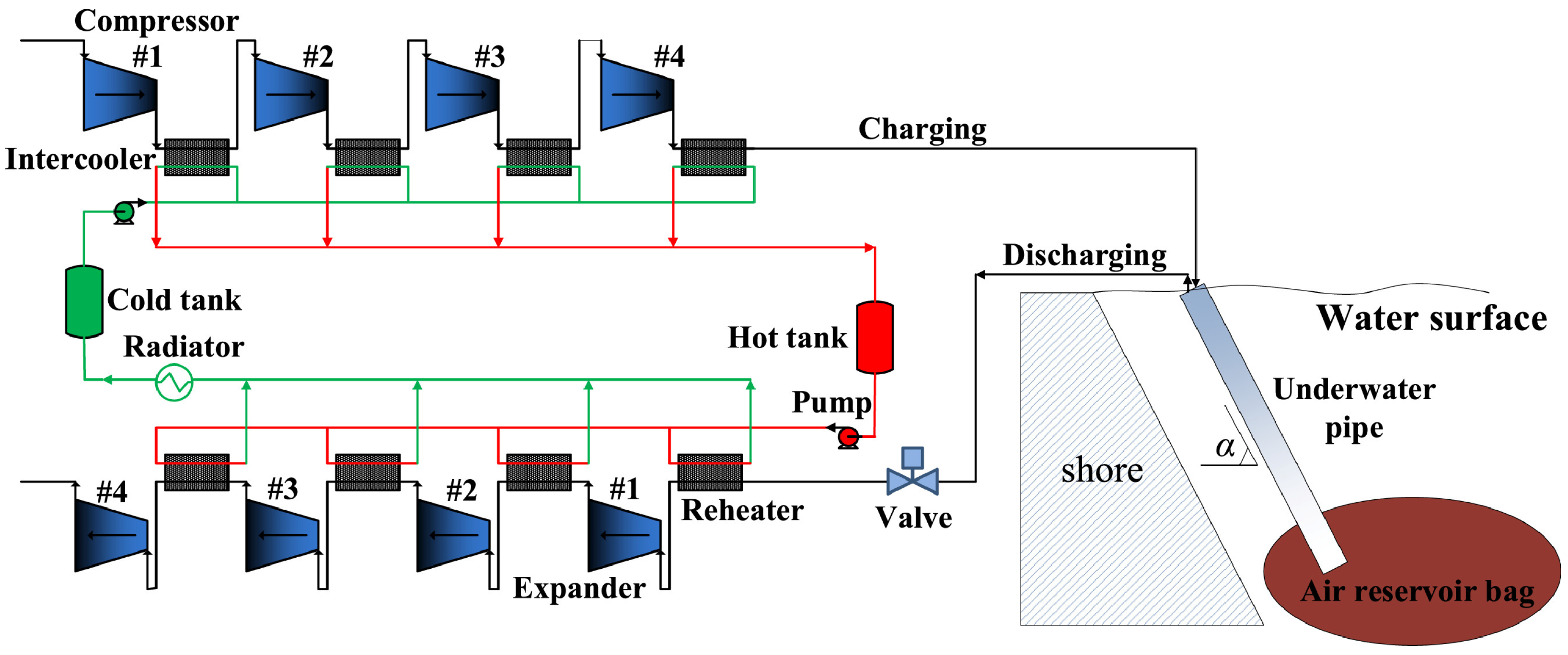
| [68] | Model | Hydrostatically compensated underwater CAES | 10 MW, 4 h discharge; 70 bar discharge pressure; four compression/expansion stages; 0.45 m underwater pipe | System efficiency of 70.74%; reported energy density of 26.07 MJ/m3 including thermal-storage tank volumes | Pipe diameter and heat-exchanger design affect losses and costs; density is not based on air-reservoir volume alone |
| [69] | Model | Active water compensation with a sealed-air accumulator | Constant CAES tank pressure; variable accumulator pressure; water pumping during charging and hydraulic recovery during discharge | Air-storage pressure can remain constant while hydraulic-machine loading varies | Overlaps with hybrid systems; no heat-free electrical RTE is assigned here |
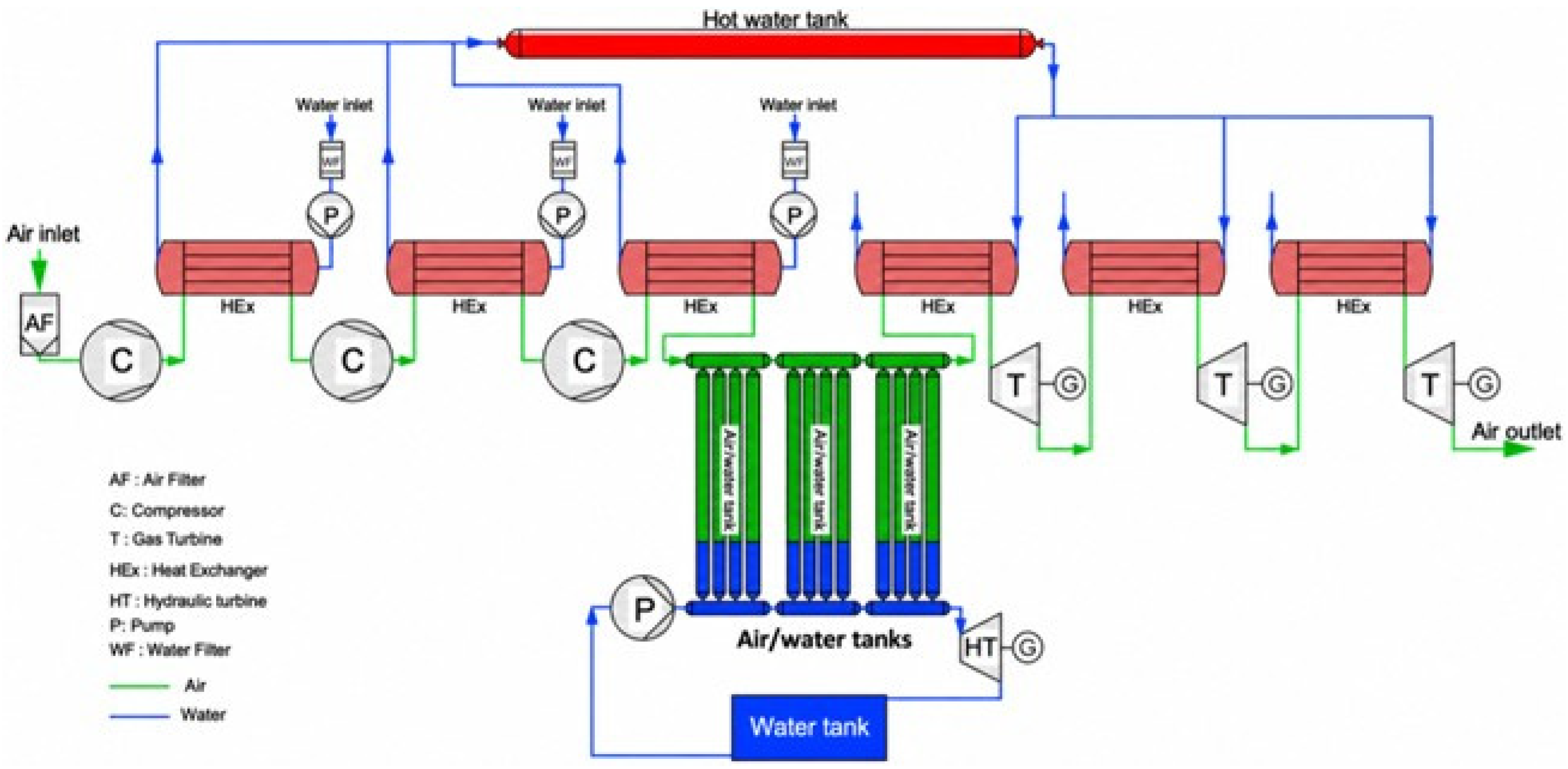
| [70,71] | Model | Actively compensated IA-CAES with hydraulic work recovery | Storage pressure approximately 120 bar; three compression/expansion stages; Pelton recovery during charging, return pumping during discharge, and start-up/standby operation | Efficiency of 55.1%, optimised to 56.6%; charging/discharge power stabilisation of approximately 120/382 s; standby shortens response at an energy cost | Steady-state and dynamic models; component simplifications and omitted gas-machine thermal inertia limit system-level validation |
| [75,76] | Model | Multi-machine compensable and spray-enhanced PHCAES | Staged hydraulic machinery and air expanders; two air tanks; replenishment-compressor work included; spray flow optimised for both tanks | Base electrical RTE of 67.2% with hydraulic-head excursions of approximately 11.0/12.7 m; spray optimisation increased calculated RTE to approximately 73.2% | Both studies are models; excessive spray flow reverses the benefit, and the approximately 6.0-percentage-point gain is not a prototype measurement |
| [77] | Model | Sequential hydraulic and pneumatic CA–PHES | 10 MW, 10 h discharge; hydraulic/pneumatic stage duration and pressure ratios optimised | Maximum reported energy efficiency of 71.82%; both charging and discharging use successive hydraulic and pneumatic stages | Near-isothermal storage was assumed; pressure losses in heat exchangers, caverns, vessels and connecting pipes were neglected |
| [78] | Model | Low-pressure PHCAES/high-pressure salt-cavern cascade | Low-pressure water–air chamber; variable-pressure cavern; staged gas machinery and solar reheating | Electrical output-to-input ratio of 53.82%; energy efficiency including solar heat of 41.06%; gas-turbine exhaust drives hydraulic generation | The two values use different energy-input boundaries and cannot establish superiority over storage without external heat input |
| System and Source | Investigated Scale or Storage Configuration | Efficiency Evidence | Evaluation Boundary | Principal Benefit and Associated Constraint |
|---|---|---|---|---|
| Variable-pressure PHCAES [50] | Parametric vessel model | 79.2% a, theoretical | Pump–hydraulic-turbine work ratio under isothermal assumptions | Compressed gas provides hydraulic head; changing chamber pressure alters hydraulic-machine operating conditions |
| Constant-pressure PHCAES [59] | 40 m3 working chamber and 5 m3 high-pressure receiver; model | Varies with pressure and component efficiency | Turbine work divided by pump and receiver-compressor work | Stabilises hydraulic operating pressure; requires additional compression and pressure regulation |
| Air-based GLIDES [52,55] | Nominal 3 kWh prototype; 5 kW generator; four 0.5 m3 pressure vessels | 18–24%, measured electrical RTE | Four tests with different pressure ranges and standby conditions | Demonstrates the hydraulic conversion pathway; component losses substantially reduce electrical recovery |
| PHCAES with constant-pressure discharge [60] | 100 kW-class experimental system | 51% measured electrical RTE, 63% projected b | Experimental cycle and separate component-performance scenario | Demonstrates pressure-regulated discharge; achievable efficiency remains dependent on equipment performance |
| Salt-cavern PHCAES [61] | 0.8 MW base model; economic scaling to 4 MW | 61.6%, modelled electrical efficiency | Selected pump-operating strategy | Extends storage to underground space; performance and feasibility depend on machinery matching and cavern conditions |
| PHES [82] | 100 MW/1000 MWh assessment case | Literature range 70–87%, 80% assumed | Technology assessment | Established hydraulic storage; reservoir capacity, head and civil works constrain deployment |
| Diabatic CAES [82] | 100 MW/1000 MWh salt-cavern assessment case | Approximately 52% assumed c | Electrical input plus fuel lower-heating-value input | Large-capacity underground storage; fuel use and geological conditions remain material constraints |
| A-CAES [81] | 10 MW net discharge power and 4 h discharge; model | 65.73%, modelled cycle efficiency | Net machinery-work balance d | Recovers compression heat without fuel reheating; performance depends on gas machinery and thermal storage |
| A-CAES, Feicheng project [83] | 300 MW/1800 MWh; 6 h discharge; grid-connected demonstration | 72.1%, reported rated design efficiency | Project-reported design value | Large-scale, long-duration storage; reported design efficiency should be distinguished from measured operational RTE |
| System and Source | Assessment Basis | Reported Cost | Main Limitation or Cost Driver |
|---|---|---|---|
| GLIDES [53] | Modelled pressure-vessel and underground-storage cases | Approximately USD 4700/kWh for steel vessels, USD 2100/kWh for carbon-fibre vessels, USD 715–346/kWh for pipe storage, and as low as USD 14/kWh for depleted reservoirs | Cost depends strongly on scale and storage structure; vessels account for 74–93% of small-system investment |
| Constant-pressure PHCAES [59] | Graphical comparison across power scales | Approximately USD 400–800/kW | Storage duration, price year and component-level breakdown are not specified |
| Salt-cavern PHCAES [61] | 0.8 MW base case with scaling to 4 MW | Cavern cost exceeds 60% of total investment; estimated payback decreases from approximately 11 years at 0.8 MW to 6.15 years at 4 MW | The reported scale benefit depends strongly on the assumed cavern cost and operating revenue |
| PHES [82] | 100 MW/1000 MWh; 2020 USD | USD 262.5 million, equivalent to USD 2625/kW or USD 262.5/kWh | Reservoirs, powerhouse construction and contingency dominate the estimate |
| Diabatic CAES [82] | 100 MW/1000 MWh salt-cavern system; 2020 USD | USD 118.96 million, equivalent to USD 1189.6/kW or USD 118.96/kWh | The result assumes favourable salt-dome geology and includes fuel-related infrastructure |
| System | Main Lifecycle Considerations |
|---|---|
| Variable-pressure PHCAES | Pressure-vessel or cavern construction, material use, water requirements and auxiliary electricity; no routine fuel combustion |
| Constant-pressure PHCAES | Additional high-pressure receiver, compressor and regulation equipment, together with their embodied impacts and auxiliary electricity consumption |
| PHES | Reservoirs, tunnels and concrete construction; land transformation, water availability and potential effects on aquatic ecosystems |
| CAES | Cavern construction, turbomachinery and pipelines; thermal-storage materials for A-CAES and direct fuel-related emissions for diabatic CAES |
| Study | Conditions | Quantitative Results | Main Conclusion | Limitations |
|---|---|---|---|---|
| [56] | Water flow increased from 2.5 to 20 L s−1 | Compression power density: 46.9–391.7 kW m−3; expansion power density: 43.7–271.2 kW m−3; expansion efficiency: 0.913–0.810 | Higher flow increases power density but reduces expansion efficiency | hydraulic-machine and auxiliary losses were not evaluated |
| [60] | Complete cycle, turbine–generator efficiency subsequently assumed to be 90% | Measured electrical RTE: 51%; energy density: 0.33 kWh m−3; projected RTE: 63% | Component efficiency is a major constraint on prototype-level electrical performance | The projected improvement was not experimentally verified |
| [64] | Flow: 330–1320 cm3 s−1; pressure: 0.67–4.7 MPa | Peak-temperature reduction: 120–73 K; specific-work reduction: 14.9–5.8% | Passive heat-transfer enhancement becomes less effective as the compression rate increases. | System-level efficiency was not evaluated |
| [88] | Maximum-to-optimum-initial pressure ratio: 2–3 | Tank-level storage efficiency: 92–93% | Initial and maximum pressures must be matched to obtain high storage-vessel efficiency | Electrical conversion losses are excluded |
| [89] | Spray flow: 0–10 L min−1 | At 10 L min−1, indicated efficiency reached 0.98 and modelled RTE reached 0.77 | Spray injection can reduce thermal irreversibility and move the gas process closer to isothermal behaviour | Modelled RTE lacks full-cycle experimental validation |
| [57] | Air-pressure variation of approximately 1.6 MPa | Pumping- and generating-head variations: 58.5 and 48.2 m; electrical efficiency: 59.0% in the first cycle and 62.5% averaged over repeated cycles | Pressure transfer reduces the absolute variation in hydraulic-machine operating head | Fixed machinery efficiencies obscure off-design benefits |
| [76] | Variable spray flow in two storage tanks | Air-temperature variation amplitudes reduced by approximately 78.1% and 77.3% | Spray flow has an optimum when thermal improvement and spray-pump consumption are considered together | Model-based results lack experimental validation |
Disclaimer/Publisher’s Note: The statements, opinions and data contained in all publications are solely those of the individual author(s) and contributor(s) and not of MDPI and/or the editor(s). MDPI and/or the editor(s) disclaim responsibility for any injury to people or property resulting from any ideas, methods, instructions or products referred to in the content. |
© 2026 by the authors. Licensee MDPI, Basel, Switzerland. This article is an open access article distributed under the terms and conditions of the Creative Commons Attribution (CC BY) license.
Share and Cite
Ren, Y.; Wang, G.; Huang, W.; Yin, Z.; Bai, Z.; Wang, H.; Zhang, Y.; Zhou, L.; Wang, Y.; Wang, B. Hydraulically Coupled Compressed-Air Energy Storage Systems: A Review of Configurations and Performance with Emphasis on PHCAES. Energies 2026, 19, 4402. https://doi.org/10.3390/en19184402
Ren Y, Wang G, Huang W, Yin Z, Bai Z, Wang H, Zhang Y, Zhou L, Wang Y, Wang B. Hydraulically Coupled Compressed-Air Energy Storage Systems: A Review of Configurations and Performance with Emphasis on PHCAES. Energies. 2026; 19(18):4402. https://doi.org/10.3390/en19184402
Chicago/Turabian StyleRen, Yan, Guangdong Wang, Wenjing Huang, Zhan Yin, Ziwei Bai, Huanran Wang, Yufei Zhang, Lixiao Zhou, Yao Wang, and Bo Wang. 2026. "Hydraulically Coupled Compressed-Air Energy Storage Systems: A Review of Configurations and Performance with Emphasis on PHCAES" Energies 19, no. 18: 4402. https://doi.org/10.3390/en19184402
APA StyleRen, Y., Wang, G., Huang, W., Yin, Z., Bai, Z., Wang, H., Zhang, Y., Zhou, L., Wang, Y., & Wang, B. (2026). Hydraulically Coupled Compressed-Air Energy Storage Systems: A Review of Configurations and Performance with Emphasis on PHCAES. Energies, 19(18), 4402. https://doi.org/10.3390/en19184402