


Abstract
Fuel design based on distillation fractions is crucial for advancing fuel development and optimizing combustion systems. However, the chemical diversity and broad boiling-point distribution of full-range fuels pose significant challenges for kinetic modeling. In this study, a volatility-aware, multi-component kinetic mechanism was developed for simulating the combustion of various distillation fractions from an FRF in diesel engines. The mechanism comprises 261 species and 860 reactions. Unlike conventional surrogate mechanisms designed primarily for a single fuel or narrow distillation range, the proposed framework simultaneously represents the major hydrocarbon classes, ignition quality, and boiling-point distribution of FRF. The surrogate palette includes n-pentane, n-heptane, n-decane, n-dodecane, n-hexadecane, heptamethylnonane, 1-methylnaphthalene, iso-octane, methylcyclohexane, decalin, toluene, tetralin, and 1,2,4-trimethylbenzene. These components were selected to reproduce the molecular structures, ignition characteristics, and distillation behavior of the target fuel fractions. The mechanism was further refined through targeted replacement of the toluene sub-mechanism using updated hydrogen-abstraction and benzyl-radical oxidation reactions, followed by a fuel-oriented five-stage reduction strategy involving reaction-pathway-based pruning, DRGEP reduction, isomer lumping, sensitivity/ROP refinement, and targeted rate optimization. The resulting mechanism provides reasonable predictions of ignition delay, laminar flame speed, and species profiles for pure components, surrogate fuels, and real gasoline, jet, and diesel fuels. Coupled with a three-dimensional CFD model, the reduced mechanism also reproduces the main combustion phasing, pressure-rise process, and peak in-cylinder pressure of a diesel engine at 500 and 800 r/min over the investigated intake-temperature range. Although discrepancies remain in the low-temperature/negative-temperature-coefficient regime and in the quantitative prediction of the peak apparent heat-release rate, the mechanism provides a unified and practical framework for linking FRF distillation characteristics with chemical reactivity and engine-level combustion behavior. It therefore offers a foundation for designing tailored fuels from distillation fractions for operation in extreme environments.
1. Introduction
Diesel engines are valued because they are highly thermally efficient and reliable in transportation and military equipment [1]. However, their performance deteriorates under low-temperature or high-altitude conditions, exhibiting poor cold-start capability, an over 30% efficiency loss, and combustion instability [2]. The engine structure and materials used in ICEs play an important role in determining engine durability and thermal-management performance [3]. Nevertheless, fuel–environment mismatch currently is a critical component limiting the cold-start of diesel engines [4,5]. Therefore, in recent years, fuel design has received widespread attention in improving the efficient operation of diesel engines [6].
The most prevalent fuel design approach involves wide distillation fuel (WDF), which is synthesized through direct blending of gasoline and diesel. WDF combines diesel’s high-carbon ignitability with gasoline’s low-carbon volatility to control fuel–air mixing and combustion reaction rates. However, its low cetane number (CN) compromises ignition performance, particularly under cold-start conditions. Valentino et al. [7,8] found that gasoline–diesel blends (20–40% vol. gasoline) exhibit prolonged ignition delays caused by CN reduction. Liu [9] further demonstrated that WDF needs a CN increase of 5–10 units (without altering physical properties) to balance low-load combustion stability and high-load emissions. In contrast, full distillation fuel (FDF) inherently satisfies these criteria without requiring cetane enhancement. The FDF, proposed by Wang et al. [10,11], encapsulates the total distillation range of gasoline, diesel, and kerosene fuel. It is produced directly from petroleum using distillation and refining processes similar to those for conventional oils. This could simplify the petroleum refining process and support the development of unified internal combustion engines (ICEs).
While FDF demonstrates advantages in alleviating the emission–efficiency trade-off, its ignition reliability and combustion characteristics under cold-start conditions are still unclear. Diesel engine combustion involves confined-space turbulence–chemistry interplay. Experimental investigations must therefore be augmented with integrated computational fluid dynamics (CFD) and chemical kinetics modeling. These sorts of approaches enable precise resolution of turbulence–heat transfer–combustion coupling effects during cold-start ignition. However, the wide distillation range (313–623 K) and complex composition of FDF hinder detailed kinetic model development for CFD simulations. To address this constraint, a reduced kinetic model for surrogate fuels—simplified hydrocarbon mixtures replicating critical FDF properties—is needed. The model circumvents computationally prohibitive full-component simulations while maintaining predictive accuracy for extreme-condition combustion analysis.
However, single-component proxies cannot accurately replicate the complex traits of actual fuels, because real fuels are multicomponent blends of alkanes, cycloalkanes, and aromatics. Recent studies [12,13] demonstrate that multicomponent surrogates are essential to faithfully reproduce target fuel behavior. When predicting engine ignition characteristics with primary reference fuel (PRF, comprising iso-octane and n-heptane), models often significantly underestimate ignition delay times under the influence of low temperatures. In contrast, aromatic hydrocarbons in toluene reference fuel (TRF, iso-octane, n-heptane, and toluene) have low reactivity. They suppress low-temperature autoignition, prolong the overall ignition delay time, and substantially improve the predictive accuracy and reliability of combustion simulations [14]. Zhang et al. [15] studied the effect of temperature on RP-3 ignition delay times in a shock tube. They compared a single-component surrogate (n-decane) and a multi-component surrogate (1,2,4-trimethylbenzene/n-decane, 20/80 wt.%). The single-component surrogate showed a global activation energy (40.3 ± 1.7 kcal/mol) significantly higher than that of RP-3 (32.4 ± 0.8 kcal/mol), while the binary surrogate closely matched RP-3. Liu et al. [16] and Mao et al. [17] further characterized RP-3 fuel properties by studying the effects of alkylbenzenes and biphenyl structures. Similarly, the development of diesel surrogate fuels has followed a comparable trajectory [18,19]. To improve the replication fidelity of target fuel properties, Mueller et al. [20] incorporated molecular structural parameters covering all principal hydrocarbon classes (n-paraffins, iso-paraffins, monocyclic/bicyclic naphthenes, mono-/di-aromatics, and naphtho-aromatics), together with ignition-quality and distillation characteristics. Their nine-component surrogate fuel showed mean property deviations within 5% of target specifications.
Current surrogate fuel kinetic mechanisms mainly focus on individual fuel types such as gasoline, kerosene, and diesel [21,22,23,24,25,26,27,28,29,30,31,32]; FDF characterization remains at a nascent stage. Building on previous successful experiences in multi-component fuel characterization, Ren et al. [33] reduced a chemical kinetic mechanism for wide distillation fuels (WDF) comprising 13 components: ethanol, methanol, toluene, iso-octane, n-decane, n-dodecane, n-heptane, n-hexadecane, diisobutylene (DIB), cyclohexane (CHX), and methylcyclohexane (MCH). However, as demonstrated by Mueller et al. [20], the existing FDF mechanism includes only single-ring cycloalkanes and monocyclic aromatics and therefore cannot represent the complex molecular structure of FDF. The CRECK group [34] developed a multi-component mechanism covering the seven primary hydrocarbon classes. However, it contains 17,790 elementary reactions, creating an excessive computational burden for CFD simulations.
Building on the comprehensive chemical kinetic framework developed by the CRECK group, this study develops a reduced volatility-aware, multi-component surrogate mechanism for combustion of the distillation fractions of a full-range fuel (FRF). The resulting FRF mechanism comprises 261 species and 860 elementary reactions. Its novelty lies in establishing a unified kinetic modeling framework that simultaneously captures the chemical-class diversity, ignition quality, and boiling-point distribution of FRF rather than representing a single fuel or only a narrow distillation range. The framework combines targeted refinement of aromatic chemistry, including the toluene sub-mechanism, with a fuel-oriented five-stage mechanism-reduction strategy to balance computational efficiency and predictive fidelity. The reduced mechanism is rigorously validated against fundamental combustion characteristics, including ignition delay times, laminar flame speeds, and species concentrations, and it is further evaluated in three-dimensional CFD simulations of diesel-engine combustion. By linking fraction-dependent volatility characteristics to chemical reactivity and engine-level combustion behavior, the proposed mechanism provides an advanced computational tool for hydrocarbon fuel engineering, supports the optimization of cold-start ignition stability and operational reliability in compression-ignition engines, and establishes a basis for designing tailored fuels from FRF distillation fractions for extreme operating environments.
2. Mechanism Development
This study identified 14 components as the surrogate palette for FRF, encompassing the major hydrocarbon classes: n-alkanes (n-decane, n-dodecane, n-eicosane, n-heptane, n-hexadecane, and n-pentane); iso-alkanes (iso-octane and heptamethylnonane); mono-cycloalkane (MCH), di-cycloalkane (decalin); mono-aromatics (toluene, 1,2,4-trimethylbenzene), naphtho-aromatic (tetralin); and di-aromatic (1-methylnaphthalene) (Table 1). These components define a property space that bounds the key distillation, ignition, and structural characteristics of FRF. The boiling points range from 309 to 617 K, densities range from 0.626 to 1.025 g·cm−3, and cetane numbers range from −3 to 110.
Table 1.
Pure compounds that make up the surrogate palette.
It is noteworthy that a validated kinetic mechanism for n-eicosane is unavailable. Following the approach in Ref. [35], this paper represents the chemical reactivity of n-eicosane using the validated sub-mechanism of n-hexadecane while retaining the physical properties (e.g., boiling point, density) of n-eicosane itself for property calculations. Specifically, a pseudo-species approach is adopted to represent the fuel chemistry for n-eicosane while maintaining computational efficiency. The liquid-phase n-eicosane spray is modeled using the genuine physical and thermodynamic properties of C20H42, such as density, viscosity, surface tension, vapor pressure, boiling point, latent heat of vaporization, and molecular weight, which govern the spray atomization, wall impingement, and evaporation processes within the CONVERGE CFD solver. A species entry labelled NC20H42 is also introduced in the mechanism file, along with the conversion reaction NC20H42 => NC16H34. It must be emphasized that this reaction is strictly a numerical mapping step rather than a physical cracking or isomerization reaction. To ensure strict elemental and mass conservation during this mapping, the pseudo-species NC20H42 is assigned the elemental composition and molecular weight of NC16H34 (i.e., C16H34) in the thermodynamic database (thermo.dat). Consequently, the element balance of the conversion reaction is exactly satisfied, and the global fuel mass tracked by the spray solver is conserved upon transfer to the gas-phase chemical solver. It should be noted that this methodology captures the physical spray behavior of n-eicosane accurately but approximates its gas-phase oxidation kinetics using the n-hexadecane reaction network.
2.1. Targeted Optimization of the Toluene Sub-Mechanism
The foundational chemistry in this work is built upon the detailed CRECK mechanism (2020 version). Although this mechanism performs well for many components, preliminary validation revealed systematic under-predictions of laminar flame speeds for toluene at 1 atm and 298 K, as shown in Figure 1. To address this without introducing a completely new mechanism, a targeted replacement strategy was adopted instead of a full model merger. The critical chemical reactions influencing the laminar flame speed of toluene primarily involve three stages: The initial stage is hydrogen abstraction from the methyl group of toluene to form the benzyl radical (C6H5CH2•); the second stage comprises oxidation pathways of the benzyl radical (C7H7•); the third stage involves the final oxidation and energy release of small molecules (e.g., CO/H2). This study replaced the hydrogen abstraction sub-mechanisms of toluene in the CRECK model with those from the reduced LLNL-based mechanism developed by Marco et al. [36]. The primary modification focuses on updating the rate constants for key reactions such as OH + C7H8 → H2O + C7H7. In the original detailed CRECK mechanism, these rates are relatively lower, leading to diminished overall reactivity in flame propagation. Figure 1 compares the toluene laminar flame speed predictions at 1 atm and 298 K using the new mechanism and the original detailed CRECK mechanism, alongside experimental data. The results demonstrate that this targeted replacement effectively resolves the underestimation issue across the equivalence ratio range of 0.8–1.1, with errors reduced to below 3% against the experimental data of Davis et al. [37]. This targeted approach keeps the well-validated core of the CRECK mechanism for other fuel classes entirely intact.
Figure 1.
Comparison of laminar flame speeds for toluene for the merged mechanism and the detailed CRECK mechanism under conditions of 1 atm and 298 K. The experimental data are obtained from Reference [37].
2.2. Five-Step Systematic Reduction Method
To reduce the complexity of the detailed CRECK mechanism (492 species, 17,790 reactions) while maintaining high predictive fidelity, this study proposes a five-stage systematic reduction workflow. Unlike conventional single-step methods, the proposed approach incorporates multi-objective screening, iterative cross-validation, and a conservative safety-net strategy. This enables both computational efficiency and robust predictive performance. The procedure is illustrated in Figure 2 and comprises the following stages.
Figure 2.
Mechanism reduction methodology.
The first step is the fuel-specific pruning via rate-of-production (ROP) analysis: ROP analysis is performed in a closed homogeneous batch reactor for each FRF surrogate component using the detailed CRECK mechanism. This step removes species and reactions entirely unrelated to the target fuel classes (e.g., olefins and oxygenated intermediates). To safeguard flame propagation and heat-release pathways, a conservative retention criterion is applied: any reaction contributing to the consumption of core fuel components or to the formation of major products (CO, H2O) is retained, regardless of its apparent minor contribution.
The second step is the broad-range directed relation graph with error propagation (DRGEP) compression: The DRGEP method is applied to the mechanism from Step 1 to further eliminate insignificant species and reactions. This analysis covers a wide parameter space (T = 600–1400 K, φ = 0.5–1.5, P = 1–40 atm) to ensure accuracy across diverse operating conditions. The reduction is performed iteratively. In each iteration, ignition delay times predicted by the reduced mechanism are compared against those from the previous iteration. To prevent error accumulation, this paper imposes a strict internal checkpoint: After every 3–5 iterations, the reduced mechanism is benchmarked against the original detailed CRECK mechanism. The reduction process is terminated immediately if the accumulated global error exceeds a 10% threshold. In this work, a 10% global error tolerance was adopted as the engineering accuracy criterion for mechanism reduction. This value is sufficiently stringent to ensure predictive reliability while still achieving meaningful size reduction. The global error is defined as the maximum relative deviation between the reduced and detailed mechanisms over all selected validation conditions, covering not only ignition delay but also key species concentrations (including surrogate components, O2, H2O, CO, and CO2).
The third step is isomer lumping: The mechanism derived from DRGEP still contains numerous isomers with similar chemical properties. To reduce the total species count, isomer lumping was used to select representative isomers for each chemical class. Post-lumping, the altered coupling between components made it necessary to reapply DRGEP to eliminate remaining noncritical species and reactions. This iterative process continued until the deviation in ignition delay predictions exceeded 10%, at which point simplification was terminated.
The fourth step is iterative refinement via sensitivity and ROP analysis: An iterative loop combining sensitivity analysis and ROP analysis is employed for final fine-tuning. This stage rigorously assesses the impact of removing a candidate species or reaction on the mechanism’s ability to predict key combustion targets. The iteration continues until the mechanism reaches an optimal scale—defined as the point where removing any additional species or reaction would cause the ignition delay prediction error to exceed 5%. Sensitivity analysis and ROP analysis were iteratively alternated with DRGEP to systematically map interdependencies within the reaction network. This efficiently identified redundant components and pathways, which is key to rapidly reducing the mechanism scale while maintaining kinetic fidelity.
The final step is mechanism validation and targeted rate optimization: In this final stage, the reduced mechanism is validated against a comprehensive set of experimental data, including ignition delay times, laminar flame speeds, and species concentrations. Targeted rate optimization is a method that optimizes key reaction rate constants to match experimental data. It is commonly used during mechanism validation as an effective strategy to reproduce experimental values with a smaller mechanism [18,38,39]. Based on a global sensitivity analysis across the full temperature range (600–1400 K), a limited set of the most influential reactions (typically about 10) is identified for rate-constant optimization. This rigorous calibration step ensures that the final reduced mechanism is not only compact but also quantitatively predictive.
Through this systematic workflow, a reduced FRF mechanism comprising 261 species and 860 reactions was developed. This represents a substantial reduction from the detailed mechanism while maintaining high predictive accuracy. Table 2 shows the summary containing the number of species, number of reactions, reduction ratio, and applicable temperature and pressure ranges.
Table 2.
Summary of reduction.
All thermodynamic and reaction data for the reduced mechanism are provided in the Supplementary Materials. The present mechanism is intended primarily for petroleum-derived fuels within the gasoline-to-diesel distillation range (approximately 313–623 K) and for combustion conditions of 700–1600 K and 1–80 bar; its use for heavier fractions, ultra-high-pressure conditions, or lower-temperature regimes should therefore be accompanied by further kinetic development and validation. Although the incorporated low-temperature oxidation and cross-reaction chemistry provides a basis for application to LTC and potentially HCCI/RCCI combustion, dedicated validation under the wider ranges of dilution, reactivity stratification, and two-stage ignition behavior characteristic of these modes is required. Future work will extend the mechanism toward advanced combustion strategies and sustainable fuels, particularly oxygenated biofuels, by incorporating fuel-class-specific sub-mechanisms and validating their ignition, oxidation, and emissions behavior.
3. Mechanism Validations
The data for ignition delay, laminar flame speeds, and species concentrations obtained from fundamental experiments provide crucial benchmarks for the performance evaluation of mechanisms [40,41]. Based on these data, this study systematically validates the accuracy of the reduced FRF mechanism, covering pure components, various alternative fuels, and real fuels (e.g., gasoline, aviation kerosene, diesel). Given that the combustion processes in diesel engines are highly influenced by multiple physical factors, such as in-cylinder turbulence, transient operating conditions, fuel injection strategies, and wall heat transfer, this study further employs three-dimensional computational fluid dynamics (3D-CFD) simulations to assess the feasibility of the reduced FRF mechanism in real diesel engine combustion.
3.1. Validation of Ignition Delay
Based on the operating mode of compression ignition, it is necessary for the reduced FRF mechanism to apply an accurate prediction of ignition delay under broad operating conditions for diesel engines. The ignition delay simulations are carried out within a closed, constant volume, homogeneous model of the CHEMKIN package [42]. These experimental methods and data sources are shown in Table 3.
3.1.1. The Ignition Delay of Pure Components
Validation of ignition delay for pure components is a necessary prerequisite for ensuring mechanism accuracy, laying the foundation for subsequent multi-component prediction. Figure 3 presents a comparative analysis between numerical simulations of the reduced FRF mechanism and the ignition delay from experimental sources for n-alkanes (NC5H12, NC7H16, NC10H22, NC12H26, and NC16H34). The “present” term in all the figures of this paper represents the data calculated using the reduced FRF mechanism. For NC5H12, NC7H16, and NC10H22 (Figure 3a–c), the mechanism quantitatively replicates experimental negative temperature coefficient (NTC) trends and temperature–pressure correlations. Figure 3d compares simulated and experimental ignition delay for stoichiometric NC12H26/air blends at 20 atm and 40 atm. The mechanism closely replicates experimental trends at 20 atm but systematically underestimates ignition delays below 1000 K at 40 atm. This deviation aligns with recent studies identifying inherent limitations in modeling ignition under high-pressure/low-temperature conditions, suggesting that future work should focus on acquiring more experimental data to make the necessary improvements to the NC12H26 sub-mechanism [33,43].
Figure 3.
Ignition delay comparison between the numerical simulations using the reduced FRF mechanism and experimental [44,45,46,47,48,49,50] results for n-alkanes.
For NC16H34 (Figure 3e), on account of the shortage of experimental data for pure NC16H34, the ignition delay time of an NC16H34/air mixture with only a high-temperature range of 1230–1800 K at a pressure of 4 atm and an equivalence ratio of 1.0 is shown in Figure 3e. Furthermore, Figure 4 presents the simulated ignition delay of NC16H34 within the temperature range of 700–1200 K, obtained using Chemkin. It can be observed that the ignition delay curve of NC16H34 under the current FRF mechanism exhibits pronounced NTC behavior. This comparison with the ignition delay profile of NC12H26 is consistent with the conclusion reported in Ref. [30]; that is, heavy n-alkanes show similar ignition delay for intermediate and high-temperature regimes, with the primary differences occurring in the low-temperature and NTC regions. In short, the mechanism created in this study represents the ignition delay characteristics of NC16H34.
Figure 4.
The ignition delay comparison of NC16H34 and NC12H26.
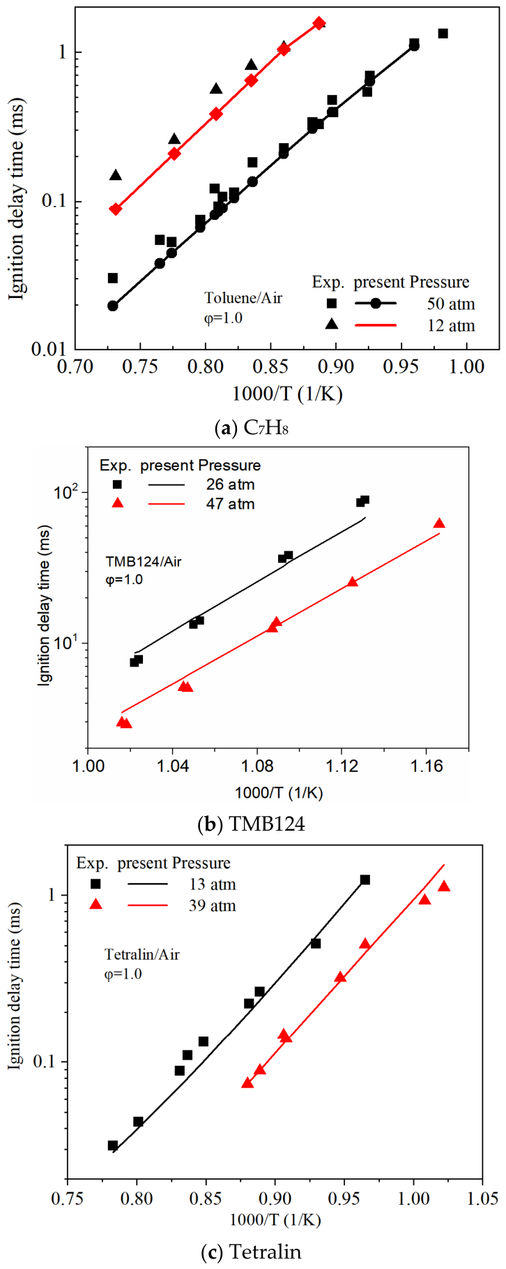
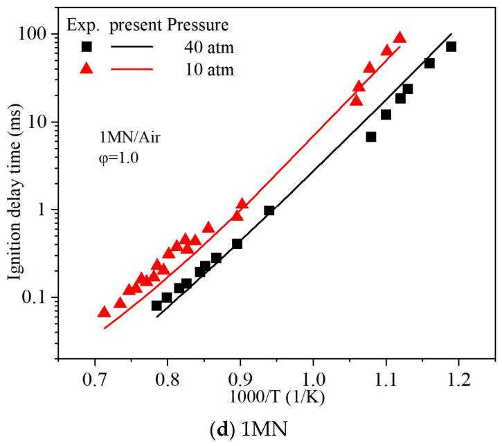
Figure 5, Figure 6 and Figure 7 compare experimental data and simulated ignition delays for isoalkanes (isooctane, IC8H18), cycloalkanes (methylcyclohexane, decalin), and aromatics (C7H8, TMB124, tetralin, 1MN), respectively. The results demonstrate overall predictive accuracies within engineering tolerances.
However, as Figure 5b shows, the model slightly overestimates the ignition delays of IC16H34 under lean conditions (φ = 0.5) and low temperatures (T < 1000 K). Despite this, the predictions remain within the same order of magnitude. Furthermore, the reduced FRF mechanism accurately captures the decreasing ignition delay trend with increasing equivalence ratios. Unfortunately, the lack of experimental data at low temperatures and within the NTC region necessitates further validation of the IC16H34 mechanism in future studies.
In Figure 6b, the simulated ignition delay curve for decalin at p = 12 atm exhibits a slope discrepancy compared to the experimental data fitting line, within an error of approximately 10%. This level of error is acceptable given that the uncertainty in shock tube ignition experiments can reach ±20% [51]. Additionally, no indication of NTC behavior for decalin is observed within the investigated temperature range, suggesting weaker low-temperature reactivity compared to MCH.
Validation using pure components reveals that, despite inherent theoretical limitations in the current model, its demonstrated sensitivity to pressure, temperature, and concentration parameters enables quantitative prediction of ignition delay times in practical combustion systems. This confirms the model’s potential applicability under complex operational conditions.
Figure 5.
Ignition delay comparison between the numerical simulations using the reduced FRF mechanism and experimental [51,52] results for iso−alkanes.
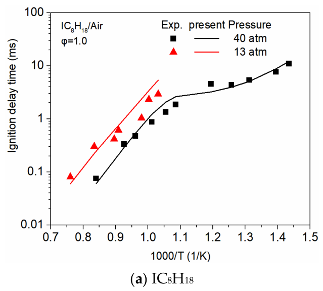
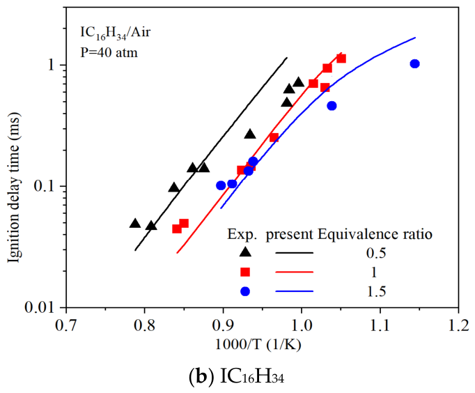
Figure 6.
Ignition delay comparison between the numerical simulations using the reduced FRF mechanism and experimental [53,54] results for cycloalkanes.
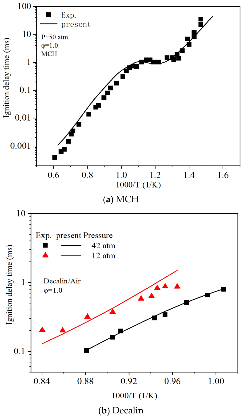
Figure 7.
Ignition delay comparison between the numerical simulations using the reduced FRF mechanism and experimental [18,55,56,57] results for aromatics.
3.1.2. The Ignition Delay of Surrogate and Actual Fuels
Given that practical fuels are complex blends potentially composed of hundreds of molecules, for which their combustion involves intricate physicochemical interactions resulting in ignition characteristics that cannot be simply regarded as the total of those of individual pure components, it is necessary to assess the ignition delay times of both surrogate and real fuels in addition to pure-component verification. All experimental data and the structure of the substitute fuels used are presented in Table 3.
Figure 8a,b, and 8c show the experimental and computed ignition delays for the gasoline surrogate PRF 70 (NC7H16/IC8H18 = 33/67 mole%) and real gasoline, respectively. As shown in Figure 8a,b, the model predictions for the well-defined surrogate fuel PRF 70 exhibit good agreement with experimental data across the tested conditions. However, Figure 8c reveals that, when simulating real gasoline using a surrogate fuel blend (NC7H16/IC8H18/C7H8 = 17/69/14 mole%), the present mechanism is inclined to minutely underestimate the ignition delay at low temperatures and overestimate it at high temperatures for φ = 1.0. This deviation is anticipated, primarily due to the absence of olefinic components in the reduced FRF mechanism compared to the complex composition of real gasoline.
Figure 8d,e compare the simulated and experimental ignition delays for kerosene fuel POSF 4658 and real Jet-A jet, respectively. As shown in Figure 8d, the current mechanism accurately captures the ignition behavior in the low-temperature and NTC regions while slightly overpredicting the ignition delays at high temperatures (>1100 K). Despite this minor discrepancy at high temperatures, the predictions represent a significant improvement over literature results [58].
Figure 8.
Ignition delay comparison between the numerical simulations using the reduced FRF mechanism [18,26,58,59,60,61] results for surrogate and real fuels.
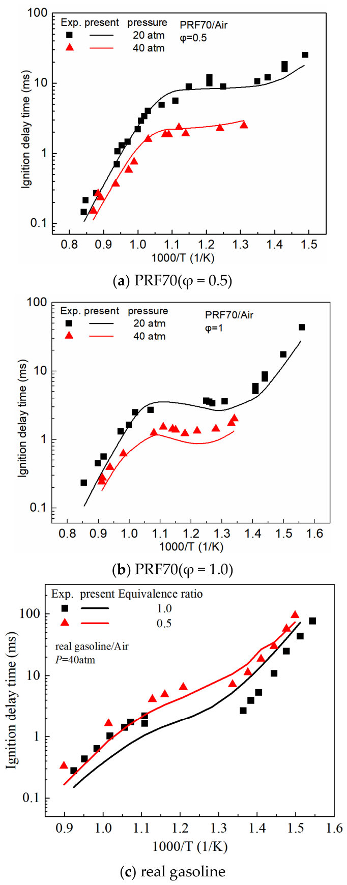
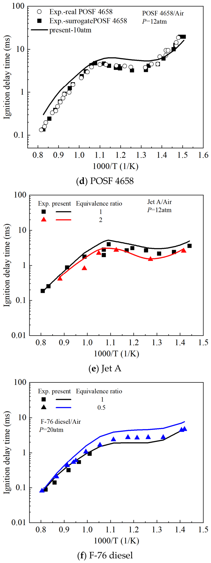
Table 3.
Summary of experimental data for ignition delay validation.
Figure 8f compares measured and computed ignition delays for F-76 diesel/air mixtures within a shock tube. Both the surrogate fuel mixture utilized for this study (50.39% NC10H22, 10.56% iso-cetane, 12.86% MCH, and 26.19% C7H8) and the experimental data are procured from Reference [18]. The results indicate that, for an equivalence ratio of 0.5, this model overpredicts the time of the ignition delay under low-to-intermediate temperature conditions. This discrepancy is primarily attributed to two factors: (1) Under low-temperature and high-pressure environments, non-ideal facility effects compromise the reliability of assuming a constant volume within shock tube experiments, which is particularly pronounced for long-ignition delay-time fuels. (2) Differences exist between the combustion characteristics of the substitute fuel and those of the actual F-76 diesel.
3.2. Validation of Laminar Flame Speed
The laminar flame speed (LFS) provides essential insights into the reactivity, diffusivity, and key physicochemical properties. In this study, the reduced FRF mechanism was verified against laminar flame speed data utilizing the CHEMKIN package’s PREMIX module. The calculations employed a finite differential method with an adaptive grid, incorporated mixture-averaged transport methodology, and accounted for thermal diffusion via the Soret effect. These experimental methods and data sources are summarized in Table 4. It should be noted that, due to the lack of experimental laminar flame speed data for tetralin and 1MN, these fuels are excluded from the validation of laminar flame speeds for pure components.
Table 4.
Experimental data for laminar flame speed validation.
3.2.1. The Laminar Flame Speeds of Pure Component
Figure 9a–e present a comparative analysis of laminar flame speed data between numerical simulations using the reduced FRF mechanism and experimental results for n-alkanes (NC5H12, NC7H16, NC10H22, NC12H26, and NC16H34), respectively. Overall, the simulations provide strong correlations with the experimental LFS data. However, a slight overprediction is observed under lean fuel conditions at elevated pressures (P = 5 atm) for NC5H12, NC7H16, and NC12H26. Furthermore, as displayed in Figure 9c, the anticipated LFS for NC10H22 is systematically underpredicted compared to the experimental values. This discrepancy highlights a common challenge in the current development of kinetic mechanisms and warrants further investigation [76].
Figure 9.
Laminar flame speed contrasts between the experimental [62,63,64,65,66] and simulated results utilizing the reduced FRF mechanism for n-alkanes. The experimental data ■ and □ are taken from [62,63] in Figure 9a, respectively.
Figure 9f further compares the simulated LFS for all five n-alkanes calculated with the reduced FRF mechanism, demonstrating that the LFS values from C5 to C16 are remarkably similar. These findings underscore that the LFS of heavier n-alkanes is primarily susceptible to the oxidation kinetics of small intermediate species but is relatively insensitive to reactions involving the initial decomposition of the large fuel molecules before generating these intermediates.
Figure 10a illustrates the impact of pressure on the laminar flame speeds of IC8H18 [67]. Although the predicted LFS exhibits a systematic overprediction of approximately 1–3 cm/s at 2 atm and 5 atm, the overall agreement with experimental measurements is good, particularly in capturing the pressure-dependence trend. As shown in Figure 10b, for IC16H34, the experimental and calculated LES also show good agreement, with slight overpredictions at φ < 1.0 and slight underpredictions at φ > 1.0.
Figure 10.
Laminar flame speed comparison between the experimental [66,67] and simulated results utilizing the reduced FRF mechanism for iso-alkanes.
Figure 11 and Figure 12 present comparisons between experimentally measured and simulated LFS for cycloalkanes (MCH, decalin) and aromatics (C7H8, TMB124), respectively. The results indicate that the overall predictive accuracy remains within acceptable engineering tolerances. Specifically, Figure 11a shows that MCH’s simulated laminar flame speeds are consistently overpredicted by more than 5 cm/s compared to the experimental values, a deviation aligned with prior studies [33,76], necessitating further refinement of the MCH sub-mechanism in subsequent work. Figure 12b plots measured versus calculated laminar flame speeds for TMB124. Although a slight overprediction is observed under φ < 1.1 (fuel-lean) and at p = 3 atm, both the predicted peak flame speed and the overall trend demonstrate satisfactory agreement with experimental data.
Figure 11.
Laminar flame speed comparison between the experimental [68,69] and simulated results utilizing the reduced FRF mechanism for cycloalkanes.
Figure 12.
Laminar flame speed contrast between the experimental [37,65,70] and simulation results using the reduced FRF mechanism for aromatics.
Validation using pure components reveals that, despite minor deviations from experimental data attributable to current limitations in mechanism development, the demonstrated sensitivity of the reduced FRF mechanism to pressure, temperature, and mixture concentration enables the quantitative prediction of laminar flame speeds in practical combustion systems. Consequently, the predictive performance of the reduced FRF mechanism is acceptable for engine applications.
3.2.2. The Laminar Flame Speeds of Surrogate and Actual Fuels
The laminar flame speeds of different actual fuels (gasoline, diesel, and kerosene) were also utilized to validate the applicability of the reduced FRF mechanism. All experimental data and surrogate fuel compositions used are summarized in Table 4, and the validation results are depicted in Figure 13 and Figure 14. As shown in Figure 13a, the surrogate gasoline fuel, composed of IC8H18, NC7H16, and C7H8 at a 1:1:1 volume ratio, accurately predicts the laminar flame speed of real gasoline across varying temperatures.
Figure 13.
Laminar flame speed contrast between the experiment [71,75] and numerical simulations using the reduced FRF mechanism for real gasoline and diesel surrogate and real fuels.
Figure 14.
Laminar flame speed contrast between the experiment [72,73,74] and numerical simulation results using the reduced FRF mechanism for real jet fuels. The experimental data of Jet A (■, ▼) and POSF 4658 (□,  ) are obtained from [73,74] in Figure 14b, respectively.
Figure 14a,b utilize a ternary molar surrogate composed of NC10H22 (82.1%), MCH (7.9%), and C7H8 (10%) and binary Aachen surrogates (NC10H22/TMB124 = 80/20 wt.) to represent real Jet-A fuel, respectively. The results demonstrate that although the calculated laminar flame speeds are slightly smaller than the experimental laminar flame speeds of Jet A, the overall trends exhibit excellent replication. Surrogate fuel A (NC10H22/IC8H18/MCH/C7H8 = 50.39/10.56/12.86/26.19 mol%) and surrogate fuel B (NC10H22/IC8H18/MCH/C7H8 = 26.67/14.89/36.81/21.64 mol%) were selected to predict the laminar flame speeds of actual diesel [75]. From Figure 13b, both surrogate fuels can accurately predict the experimental data, indicating that variations in surrogate fuel composition have a minimal effect on predicted laminar flame speeds.
Surrogate fuel A (NC10H22/IC8H18/MCH/C7H8 = 50.39/10.56/12.86/26.19 mol%) and surrogate fuel B (NC10H22/IC8H18/MCH/C7H8 = 26.67/14.89/36.81/21.64 mol%) were selected to predict the laminar flame speeds of actual diesel [75]. From Figure 13b, both surrogate fuels can accurately predict the experimental data, indicating that variations in surrogate fuel composition have a minimal effect on predicted laminar flame speeds. This insensitivity stems from the fact that laminar flame speeds exhibit higher sensitivity to reactions involving H2, CO, and small hydrocarbon species than to fuel-related reactions [43]. Figure 13b and Figure 14 collectively indicate that there is no unique composition for constructing surrogate fuels: the optimal surrogate should be determined through iterative testing and adjustment during the construction process.
3.3. Validation of Species Concentrations
Species concentration validation is indispensable in constructing chemical reaction mechanisms, as it directly constrains elementary reaction pathways (e.g., free radical chain propagation, intermediate species kinetics) at the microscopic level, thereby overcoming the limitation of global parameters that only characterize macroscopic behavior [77]. Simultaneously, such validation imposes strong constraints on reaction rate constants to reduce parameter uncertainty. Based on the available measured data, this paper employs the premixed flame burner (PFB) and jet-stirred reactor (JSR) modules in CHEMKIN to assess the mechanism against species concentration measurements. The experimental methods and data sources are outlined in Table 5. A critical consideration is that, due to the lack of experimental species concentration data for NC5H12, TMB124, and tetralin, these fuels are excluded from the species concentration validation of pure components.
Table 5.
Summary of experimental data for species concentration validation.
3.3.1. The Species Concentrations of Pure Components
Figure 15 compares simulated concentration distributions of key species utilizing the reduced FRF mechanism with experimental data for n-alkanes: NC7H16, NC10H22, NC12H26, and NC16H34. Figure 15a,b show that the model exhibits high accuracy in predicting the consumption of NC7H16, NC10H22, and O2, as well as CO2 formation. For the intermediate species H2 and H2O, discrepancies of approximately 15% are observed when compared to experimental values; nevertheless, the mechanism adequately captures their overall formation/consumption trends.
Figure 15.
Species concentration comparison between the experimental [78,79,80,81,82,83] and simulated results utilizing the reduced FRF mechanism for n-alkanes. Solid lines denote calculated values, and symbols represent experimental data (In the figure, the asterisk (*) denotes a multiplication factor for the concentration of the species shown before it. For instance, ‘5’ signifies a 5-fold multiplication relative to the number on the axis.).
As shown in Figure 15c,d, the mechanism accurately reproduces experimental trends for NC12H26 and O2 consumption, in addition to the formation of H2O, CO, and CO2 at temperatures above 800 K. This demonstrates its effectiveness in capturing the coupled thermodynamic and kinetic behavior of NC12H26 oxidation chain reactions and final product formation pathways. Notably, the mechanism successfully replicates the NTC behavior observed in O2 consumption and CO formation within the 600–800 K temperature range, confirming its ability to describe complex radical reactions during low-temperature oxidation. However, some deviations persist for components such as CO and CO2 in the low-temperature region, which is consistent with limitations reported in the literature and may be attributed to insufficient characterization of aldehyde/ketone pathways [33].
Figure 15e,f compare measured and computed species concentrations for NC16H34 at φ = 0.5 and 1. Validation was limited to 1000–1200 K due to absent low-temperature experimental data. A slight delay is observed in the predicted concentration profile of C3H6 (propylene) at φ = 0.5; however, this discrepancy is negligible given both its low concentration magnitude and substantial experimental uncertainty.
Figure 16 demonstrates a close agreement between predicted and experimental species concentrations for IC8H18 and IC16H34. Figure 17 presents predictions of key species profiles in MCH and decalin flames using the reduced FRF mechanism, validated against experimental measurements. High consistency is noted throughout the simulated and experimental data. Notably, in Figure 17c, the reduced FRF mechanism exhibits some deviations in predicting decalin concentrations at φ = 1 near the burner’s surface; however, the agreement improves downstream of the nozzle, and the predictions at φ = 1.8 are also satisfactory. Therefore, the deviations near the burner surface cannot be attributed solely to the reduced chemical mechanism. They may also result from near-nozzle flow, mixing, and thermal boundary effects that are not explicitly resolved in the present one-dimensional model [86].
Figure 16.
Species concentration comparison between the experiment [78,79,84] and simulation results using the reduced FRF mechanism for iso−alkanes. Solid lines denote calculated values, and symbols represent experimental data. (In the figure, the asterisk (*) denotes a multiplication factor for the concentration of the species shown before it. For instance, ‘5’ signifies a 5-fold multiplication relative to the number on the axis.).
Figure 17.
Species concentration comparison between the experimental [85,86] and simulated results utilizing the reduced FRF mechanism for cycloalkanes. Solid lines denote calculated values, and symbols represent experimental data. (In the figure, the asterisk (*) denotes a multiplication factor for the concentration of the species shown before it. For instance, ‘5’ signifies a 5-fold multiplication relative to the number on the axis.).
Measured and simulated mole fraction profiles of major species in C7H8 flames are displayed in Figure 18a,b. The mechanism achieves high-fidelity predictions for reactants (C7H8 and O2), inert gas (AR), and primary products (H2, H2O, CO, and CO2). Crucially, the predicted AR distribution shows excellent agreement with experimental data, demonstrating accurate quantification of molar expansion effects across wide equivalence ratios [89].
Figure 18.
Species concentration comparison between experimental [84,87] and simulated results utilizing the reduced FRF mechanism for aromatics. Solid lines denote calculated values, and symbols represent experimental data.
Figure 18c,d compare predicted and measured concentrations of reactants, intermediates, and products in 1 MN flames at φ = 0.5 and 1.0. Experimental data were obtained from a JSR at 1 atm with a constant residence time of 0.5 s. This mechanism precisely reproduces O2 consumption under all conditions. Although CO and H2 mole fractions are systematically underpredicted at elevated temperatures, the reduced FRF mechanism successfully captures their concentration evolution trends—demonstrating robust performance given the extreme chemical complexity of polycyclic aromatic fuels.
3.3.2. The Species Concentrations of Surrogate and Actual Fuels
The reduced FRF mechanism was further certified against species concentration data for both surrogate and real fuels. Table 5 summarizes all experimental conditions and fuel compositions. Figure 19 compares experimental and simulated species concentrations for these fuels.
Figure 19.
Species concentration comparison between experimental [74,88] and simulated results utilizing the reduced FRF mechanism for surrogate and real fuels. Solid lines denote calculated values, and symbols represent experimental data.
Specifically, Figure 19a presents a comparison between measured and simulated species concentrations for the nitrogen-diluted jet fuel POSF 4658 at 12.5 atm with a 1.8 s residence time. This mechanism accurately reproduces mole fraction profiles of major combustion species (O2, CO, CO2, and H2O) across the entire temperature range, despite marginally underpredicting CO concentrations in the temperature span of 850–900 K. Moreover, this mechanism successfully captures reactivity characteristics of the NTC region, indicating sufficient predictive capability for kerosene flames.
For this study, a blend of NC10H22 and 1MN was utilized as the diesel surrogate fuel, and Figure 19b,c show the contrasting results among measured and simulated molar concentrations. While the mechanism captures low-temperature experimental trends, minor discrepancies still exist between simulations and measurements. These likely stem from limitations in the IC16H34 sub-mechanism within the reduced FRF mechanism, as delineated in the preceding section.
3.4. Validation in Diesel Engine
In addition to fundamental experiment validation, engine testing is essential to ensure the reliability of the FRF reduced mechanism, as such experiments may not account for engine-specific phenomena like swirl and piston motion [90].
3.4.1. Experimental and Simulation Methods
Having established the validity of the species concentrations, engine tests were then carried out on a visual 132 mm single-cylinder diesel engine to assess the accuracy of the mechanism. Engine speed and load were controlled by a CW160 AC dynamometer (Henan Kaimai Electromechanical Co., Ltd., Luoyang, China) with an accuracy of ±2 r/min. Fuel consumption was measured by a ToCeiL-CMFG010 instantaneous fuel consumption meter (error ≤ 0.12% FS). In-cylinder pressure was recorded using a Kistler 6052C (Kistler China Co., Ltd., Hong Kong, China) pressure sensor coupled with a Kistler 2893A (Kistler China Co., Ltd., Hong Kong, China) combustion analyzer, with a sampling frequency of 0.1 °CA over 100 consecutive cycles per operating point. Intake air temperature was regulated by a tubular heat exchanger combined with an sK5β low-temperature chiller (control range: −20 °C to 40 °C; accuracy: ±0.2 °C). Coolant and lubricant oil temperatures were independently controlled by an AK52 chiller (Beijing Tongzhou Weipu Technology Co., Ltd., Beijing, China) (accuracy: ±1.0 °C) to simulate thermal boundary conditions under cold-start operations. The experimental setup follows that described in Ref. [91] and in the Supplementary Materials (File S1). The experimental setup is shown in Figure 20a. Table 6 shows a summary of the operating conditions and key engine parameters. Given the accuracy of the present mechanism in predicting ignition delay times, laminar flame speeds, and molar concentrations, -10# diesel fuel was employed solely to confirm the dependability of the FRF mechanism in this paper; its properties are listed in Table 7. To assess the predictive precision of the reduced FRF mechanism under varying operating conditions, the engine’s speed was set to 500 and 800 r/min, with intake temperatures of 0 °C, 5 °C, and 20 °C. The start of injection (SOI) timing was modified to position combustion near top dead center.
Figure 20.
(a) Schematic of engine test system. (b) The sector mesh computing network of 45° at TDC (top dead center): 0.0659904; l_y = 0505142; l_z = 0.166674.
Table 6.
(a) Specifications of the single-cylinder optical diesel engine. (b) The experimental conditions of the diesel engine.
Table 7.
The key fuel property parameters of real fuel and surrogate fuel.
Three-dimensional simulations were performed using the commercial software CONVERGE v2.3 [92], spanning from intake valve closure (IVC) to exhaust valve opening (EVO). The operating parameters are summarized in Table 8. The initial in-cylinder pressure was obtained directly from the Kistler 6052C sensor. The initial in-cylinder temperature was computed by the KiBox combustion analysis software (version: 2893AK1) from the in-cylinder pressure trace, based on thermodynamic principles and engine geometry inputs. To conserve computational resources, a 45° sector mesh representing an eight-nozzle geometry was implemented, as illustrated in Figure 20b. The basic mesh size was set to 4 mm. Fixed embedding was applied to the nozzle and wall boundaries to enhance the resolution of spray development and spray-wall impingement. Adaptive mesh refinement (AMR) was activated by temperature and velocity gradients, allowing a max refinement level of 3 and a minimum 0.25 mm cell size. RNG k-ε (Renormalization Group k-ε model) [93] was utilized to model turbulence, the KH-RT (Kelvin–Helmholtz Rayleigh–Taylor) model [94] was used to describe droplet breakup, fuel vaporization was represented by a multi-component evaporation model [95], and spray–wall interactions were treated with a wall film model [96]. The SAGE (Solver for Arbitrary Gas-Phase Equations) chemistry solver [97] was selected for the simulated combustion, as the reaction rates of individual elementary reactions could be calculated from the detailed chemical mechanism. The diesel surrogate fuel was formulated by mass as 38.02% NC10H12, 11.55% NC20H42, 7.96% IC8H18, 2.68% IC16H34, and 39.79% 1MN. As indicated in Table 7, several key diesel surrogate properties align closely with those of -10# diesel fuel.
Table 8.
Simulation operating parameters.
3.4.2. Combustion Validation in a Diesel Engine
Figure 21 and Figure 22 compare the experimental and simulated in-cylinder pressure and apparent heat release rate (AHRR) at intake-air temperatures of 0, 5, and 20 °C under starting (500 r/min) and idling (800 r/min) conditions, respectively. At 500 r/min, the simulated pressure traces show good agreement with the measured profiles for all three intake temperatures. The predicted combustion-associated pressure rise occurs in the vicinity of TDC, and the peak cylinder pressure is reproduced with only a limited deviation. At 800 r/min, the general agreement remains satisfactory, although differences between the simulated and measured pressure traces become more apparent during the compression and expansion processes. In particular, the simulated pressure can be slightly higher than the measured value before the main combustion event and can deviate during the post-peak expansion period. The effect of engine speed is reflected mainly in the crank-angle-resolved combustion evolution. Because 800 r/min corresponds to a shorter physical time for a given crank-angle interval than 500 r/min, the competition among fuel evaporation, mixing, low-temperature chemistry, and heat loss changes with engine speed. Despite this difference, the model captures the steep pressure-rise behavior and the location of the principal combustion event at both speeds. This agreement is significant because it demonstrates that the reduced mechanism preserves the relevant ignition chemistry over different physical time scales associated with starting and idling operations.
Figure 21.
Simulated/experimental comparisons of in-cylinder pressures and AHRRs at 500r/min.
Figure 22.
Simulated/experimental comparisons of in-cylinder pressures and AHRRs at 800 r/min.
A more pronounced discrepancy is observed in the AHRR profiles. Although the simulations capture the general AHRR evolution and the location of the main heat-release event, the calculated AHRR peaks are systematically higher and narrower than the experimental values at all intake temperatures and both engine speeds. The simulated peak AHRRs are approximately 1.5–2 times the measured values in several cases.
The overprediction of the AHRR peaks is likely caused mainly by experimental uncertainties in the AHRR reconstruction. The experimental AHRR is derived from measured cylinder pressure combined with a heat transfer model; thermal shock errors in the piezoelectric pressure transducer and low-pass filtering of the pressure signal can reduce the pressure rise rate and thus underestimate the AHRR peak. These effects could lead to measured values that are only about half of the simulated ones, consistent with the observed deviation. From the simulation side, the current CFD model settings, such as turbulence, spray, and wall heat transfer sub-models, may also contribute to the overprediction. Nevertheless, since the chemical mechanism has been separately validated against ignition delay times and laminar flame speeds, the factor-of-two deviation is more likely attributable to the experimental AHRR reconstruction method than to a failure of the chemical kinetics.
Therefore, the agreement in combustion phasing, pressure-rise location, and peak pressure supports the applicability of the reduced FRF mechanism for predicting the overall premixed combustion behavior under the investigated starting and idling conditions. However, the systematic overprediction of the instantaneous AHRR peak indicates that further improvement is required for quantitatively accurate heat-release-rate prediction. Future work should quantify the uncertainty of the experimental heat-release analysis by evaluating the effects of filtering, pressure referencing, heat-transfer correction, and thermodynamic-property assumptions. In parallel, the CFD physical sub-models should be further assessed using additional validation data, including spray characteristics, wall-film behavior, cycle-resolved pressure statistics, and exhaust-emission measurements.
The present validation quantifies the performance of the reduced mechanism for the selected surrogate formulation and the investigated operating conditions. The reported deviations include the effect of mechanism reduction relative to quantifying the reduction-induced errors relative to the available experimental data, but they do not represent a full propagation of uncertainties in surrogate composition, kinetic parameters, transport properties, and phase-change properties. The reduced mechanism necessarily inherits uncertainties associated with the parent kinetic model and the input thermophysical-property descriptions. Therefore, systematic uncertainty analysis should be a future research direction.
4. Conclusions
This paper developed a multi-component kinetic mechanism considering fuel volatility for the combustion of various distillation fractions from full-range fuels in diesel engines, comprising 261 species and 860 reactions. The novelty of this work lies in establishing a volatility-aware, multi-component kinetic modeling framework for full-range fuel (FRF) combustion. In contrast to conventional surrogate mechanisms that primarily target a single fuel or a narrow distillation range, the present mechanism simultaneously represents the chemical-class diversity, ignition quality, and boiling-point distribution of FRF. The framework further combines targeted aromatic-chemistry refinement with fuel-oriented mechanism reduction and is validated from fundamental combustion properties to diesel-engine CFD simulations. The conclusions derived from this work are as follows:
(1) The mechanism incorporates all major hydrocarbon classes present in FRF, including n-alkanes, mono- and dicycloalkanes, iso-alkanes, mono- and diaromatics, and naphtho-aromatics. The surrogate composition was determined by replicating the molecular structures, the quality, and the distillation characteristics of FRF, forming a parameter space that encompasses the key property ranges of ignition performance and boiling points.
(2) The foundational CRECK mechanism was refined through a targeted replacement of the toluene sub-mechanism using updated hydrogen abstraction and benzyl radical oxidation reactions from the LLNL-based model, which successfully corrected the under-prediction of laminar flame speeds under fuel-lean to stoichiometric conditions, achieving errors below 3% against experimental data. To render the detailed mechanism computationally tractable, a fuel-oriented five-stage reduction workflow was established by integrating ROP-based fuel-specific pruning, DRGEP compression with a 10% global error checkpoint, isomer lumping, iterative sensitivity/ROP refinement with a 5% fidelity cut-off, and targeted rate optimization.
(3) The mechanism demonstrates reasonable predictions for the ignition delay, the laminar flame speeds, and the species profiles across pure components, surrogate fuels, and actual fuels (gasoline, jet, and diesel), although caution should be exercised when applying it to low-temperature and NTC conditions. Furthermore, the reduced FRF mechanism coupled with the CFD model reasonably reproduces the combustion phasing, pressure-rise process, and peak in-cylinder pressure at 500 and 800 r/min over the investigated intake-temperature range. This confirms its capability to capture the main low-temperature and premixed-combustion characteristics under starting and idling conditions. However, the simulated AHRR peaks are consistently higher and sharper than the measured values. This discrepancy may result from uncertainties in experimental AHRR reconstruction, particularly pressure-signal differentiation and filtering, as well as uncertainties in the CFD spray, heat-transfer, and turbulence–chemistry interaction models. Therefore, the present model is suitable for predicting overall combustion timing and pressure evolution, while further work is required to improve the quantitative prediction of peak AHRR.
The reduced FRF mechanism provides a useful tool for simulating FRF combustion. It establishes a critical foundation for subsequent work aimed at designing tailored fuels from FRF distillation fractions for operation in extreme environments. Looking forward, several research directions merit further investigation:
(a) We will address the quantitative assessment of computational efficiency, which is not covered in the present study, and further extend the applicability of the reduced mechanism. Systematic CPU time comparisons between the reduced and parent mechanisms will be conducted under identical computational platforms and solver settings in order to quantify the actual speed-up factor and identify the computational savings achievable with the present reduction method. Memory consumption will be evaluated across different mesh scales so as to determine the memory-saving benefit of the reduced mechanism and provide guidance for selecting appropriate grid resolutions in practical simulations. The reduced mechanism will be coupled with multidimensional CFD simulations to examine its acceleration performance and parallel scalability in engineering-scale problems, thereby offering a comprehensive basis for judging its feasibility and efficiency in real-world combustion applications.
(b) The current mechanism could cover a wider operating range, particularly the ultra-high pressure regime, in order to align with the current trend toward high-power-density diesel engines. In parallel, additional experimental validation is required under engine-relevant conditions, such as spray combustion processes and optical diagnostics in constant-volume vessels.
(c) Furthermore, to enable the prediction of soot and NOx emissions—which are critical for practical engine applications and environmental regulations—the mechanism can be extended by incorporating soot formation sub-models (e.g., based on PAH chemistry or the method of moments) and NOx formation pathways (including thermal, prompt, and fuel-NO mechanisms). This extension would allow the reduced mechanism to serve as a comprehensive tool for pollutant emission studies on diesel engines.
(d) Given the observed discrepancies in the low-temperature/NTC regime, future work should prioritize systematic validation of the mechanism under low-temperature and high-pressure conditions. This would involve collecting/incorporating high-quality experimental data (e.g., ignition delay measurements in rapid compression machines at elevated pressures) to refine the rate constants of key low-temperature oxidation pathways and to improve the pressure-dependent behavior of the mechanism through more robust extrapolation or theoretical calculations. Such efforts are essential to establish quantitative reliability for cold-start and low-temperature combustion simulations.
Supplementary Materials
The following supporting information can be downloaded at https://www.mdpi.com/article/10.3390/en19174176/s1. Figure S1. Schematic diagram of the test platform. Table S1. Main technical parameters of the heavy-duty diesel engine. Table S2. Main test instruments, models, and measurement accuracies for the single-cylinder engine platform. Figure S2. Intake air flow meter. Figure S3. sK5β low-temperature chiller. Figure S4. Engine coolant connecting pipes. Figure S5. Heat exchanger.
Author Contributions
Writing—original draft preparation, G.Z.; investigation, G.Z., T.H.-Y.L., and Z.C.; formal analysis, G.Z., T.H.-Y.L., and Z.C.; methodology, G.Z.; supervision conceptualization, H.W.; conceptualization, H.W.; writing—review and editing, H.W., T.H.-Y.L., and X.L.; funding acquisition, H.W.; validation, Z.C. All authors have read and agreed to the published version of the manuscript.
Funding
This work is supported by the National Natural Science Foundation of China under Grant No. 52176098; the National Natural Science Foundation of China (No. W2433115) and the National Key Laboratory for Bio-based Transportation Fuels (Jiaxing, China); the Henan Provincial Science and Technology Research Project (No.: 252102221026); and the key project of the Education Department of Henan Province, China (No.: 25A590005). The content is solely the responsibility of the authors and does not necessarily represent the official views of the NSFC.
Data Availability Statement
The raw data supporting the conclusions of this article will be made available upon reasonable request from qualified researchers by contacting the corresponding author.
Conflicts of Interest
The authors declare no conflict of interest.
Abbreviations
| CFD | Computational fluid dynamics |
| CHX | Cyclohexane |
| CO | Carbon monoxide |
| CN | Cetane number |
| DIB | Diisobutylene |
| DRGEP | Directed relation graph with error propagation |
| FDF | Full distillation fuel |
| HCCI | Homogeneous charge compression ignition |
| JSR | Jet-stirred reactor |
| LLNL | Lawrence Livermore National Laboratory |
| MCH | Methylcyclohexane |
| NOx | Nitrogen oxides |
| NTC | Negative temperature coefficient |
| PAHs | Polycyclic aromatic hydrocarbons |
| PFB | Premixed flame burner |
| PRF | Primary reference fuel |
| ROP | Rate of production |
| TRF | Toluene reference fuel |
| WDF | Wide distillation fuel |
References
- Liu, H.; Ma, S.; Zhang, Z.; Zheng, Z.; Yao, M. Study of the control strategies on soot reduction under early-injection conditions on a diesel engine. Fuel 2015, 139, 472–481. [Google Scholar] [CrossRef] [Scilit]
- Shen, L.; Shen, Y.; Yan, W.; Xu, J. Combustion Process of Diesel Engines at Regions with Different Altitude; SAE Technical Paper; SAE International: Warrendale, PA, USA, 1995. [Google Scholar]
- Milojević, S.; Miladinović, S.; Gajević, S.; Čukić, S.; Stojanović, B. Application of Al–Si Alloys in Internal Combustion Engines. Lubricants 2026, 14, 277. [Google Scholar] [CrossRef] [Scilit]
- Weilenmann, M.; Favez, J.-Y.; Alvarez, R. Cold-start emissions of modern passenger cars at different low ambient temperatures and their evolution over vehicle legislation categories. Atmos. Environ. 2009, 43, 2419–2429. [Google Scholar] [CrossRef] [Scilit]
- Wang, X.; Ge, Y.; Yu, L.; Feng, X. Comparison of combustion characteristics and brake thermal efficiency of a heavy-duty diesel engine fueled with diesel and biodiesel at high altitude. Fuel 2013, 107, 852–858. [Google Scholar] [CrossRef] [Scilit]
- Lu, X.; Han, D.; Huang, Z. Fuel design and management for the control of advanced compression-ignition combustion modes. Prog. Energy Combust. Sci. 2011, 37, 741–783. [Google Scholar] [CrossRef] [Scilit]
- Valentino, G.; Corcione, F.; Iannuzzi, S.; Serra, S. Effects of Premixed Low Temperature Combustion of Fuel Blends with High Resistance to Autoignition on Performances and Emissions in a High-Speed Diesel Engine; Sae Technical Papers; SAE International: Warrendale, PA, USA, 2011. [Google Scholar]
- Merola, S.S.; Marchitto, L.; Corcione, F. Optical Diagnostics of the Pollutant Formation in a CI Engine Operating with Diesel Fuel Blends. SAE Int. J. Engines 2011, 4, 2543–2558. [Google Scholar] [CrossRef] [Scilit]
- Liu, H. Fundamental Investigation of Fuel Design and Premixed Low Temperature Combustion of Wide Distillation Fuels. Ph.D. Thesis, Tsinghua University, Beijing, China, 2017. [Google Scholar]
- Wang, J.; Liu, H.; Wang, Z.; Shuai, S. Combustion and Emission Characteristics of Direct Injection Compression Ignition Engine Fueled with Wide Distillation Fuel (WDF). Energy Procedia 2015, 75, 2379–2387. [Google Scholar] [CrossRef] [Scilit]
- Wang, J.; Wang, Z.; Liu, H. Combustion and emission characteristics of direct injection compression ignition engine fueled with Full Distillation Fuel (FDF). Fuel 2015, 140, 561–567. [Google Scholar] [CrossRef] [Scilit]
- Edwards, T.; Maurice, L.Q. Surrogate mixtures to represent complex aviation and rocket fuels. J. Propuls. Power 2001, 17, 461–466. [Google Scholar] [CrossRef] [Scilit] [PubMed]
- Lenhert, D.B.; Miller, D.L.; Cernansky, N.P.; Owens, K.G. The oxidation of a gasoline surrogate in the negative temperature coefficient region. Combust. Flame 2009, 156, 549–564. [Google Scholar] [CrossRef] [Scilit]
- Andrae, J.; Björnbom, P.; Cracknell, R.; Kalghatgi, G. Autoignition of toluene reference fuels at high pressures modeled with detailed chemical kinetics. Combust. Flame 2007, 149, 2–24. [Google Scholar] [CrossRef] [Scilit]
- Zhang, C.; Li, B.; Rao, F.; Li, P.; Li, X. A shock tube study of the autoignition characteristics of RP-3 jet fuel. Proc. Combust. Inst. 2015, 35, 3151–3158. [Google Scholar] [CrossRef] [Scilit]
- Liu, J.; Hu, E.; Zeng, W.; Zheng, W. A new surrogate fuel for emulating the physical and chemical properties of RP-3 kerosene. Fuel 2020, 259, 116210. [Google Scholar] [CrossRef] [Scilit]
- Mao, Y.; Yu, L.; Qian, Y.; Wang, S.; Wu, Z.; Raza, M.; Zhu, L.; Hu, X.; Lu, X. Development and validation of a detailed kinetic model for RP-3 aviation fuel based on a surrogate formulated by emulating macroscopic properties and microscopic structure. Combust. Flame 2021, 229, 111401. [Google Scholar] [CrossRef] [Scilit]
- Chang, Y.; Jia, M.; Li, Y.; Liu, Y.; Xie, M.; Wang, H.; Reitz, R.D. Development of a skeletal mechanism for diesel surrogate fuel by using a decoupling methodology. Combust. Flame 2015, 162, 3785–3802. [Google Scholar] [CrossRef] [Scilit]
- Hu, J. Combustion Reaction Mechanism of Diesel Surrogate Fuel and Numerical Simulation of Pollutant Generation. Master’s Thesis, Southwest Jiaotong University, Chengdu, China, 2016. [Google Scholar]
- Mueller, C.J.; Cannella, W.J.; Bruno, T.J.; Bunting, B.; Dettman, H.D.; Franz, J.A.; Huber, M.L.; Natarajan, M.; Pitz, W.J.; Ratcliff, M.A.; et al. Methodology for formulating diesel surrogate fuels with accurate compositional, ignition-quality, and volatility characteristics. Energy Fuels 2012, 26, 3284–3303. [Google Scholar] [CrossRef] [Scilit]
- Feng, H.; Zhang, W.; Cheng, G.; Liu, D.; An, M. Effects of Fuel Distillation and Combustion Phase on Diesel Engine Low Temperature Combustion and Emissions. Trans. CSICE 2016, 34, 210–217. [Google Scholar]
- Curran, H.J.; Gaffuri, P.; Pitz, W.J.; Westbrook, C.K. A comprehensive modeling study of iso-octane oxidation. Combust. Flame 2002, 129, 253–280. [Google Scholar] [CrossRef] [Scilit]
- Youngchul, R.; Reitz, R.D. A reduced chemical kinetic model for IC engine combustion simulations with primary reference fuels. Combust. Flame 2008, 155, 713–738. [Google Scholar] [CrossRef] [Scilit]
- Wang, H.; Yao, M.; Reitz, R.D. Development of a reduced primary reference fuel mechanism for internal combustion engine combustion simulations. Energy Fuels 2013, 27, 7843–7853. [Google Scholar] [CrossRef] [Scilit]
- Tanaka, S.; Ayala, F.; Keck, J.C. A reduced chemical kinetic model for HCCI combustion of primary reference fuels in a rapid compression machine. Combust. Flame 2003, 133, 467–481. [Google Scholar] [CrossRef] [Scilit]
- Bikas, G.; Peters, N. Kinetic modelling of n-decane combustion and autoignition. Combust. Flame 2001, 126, 1456–1475. [Google Scholar] [CrossRef] [Scilit]
- Lindstedt, R.P.; Maurice, L.Q. Detailed chemical-kinetic model for aviation fuels. J. Propuls. Power 2000, 16, 187–195. [Google Scholar] [CrossRef] [Scilit] [PubMed]
- Zeppieri, S.P.; Klotz, S.D.; Dryer, F.L. Modeling concepts for larger carbon number alkanes: A partially reduced skeletal mechanism for n-decane oxidation and pyrolysis. Proc. Combust. Inst. 2000, 28, 1587–1595. [Google Scholar] [CrossRef] [Scilit]
- Raza, M.; Mao, Y.; Yu, L.; Lu, X. Insights into the effects of mechanism reduction on the performance of n-decane and its ability to act as a single-component surrogate for jet fuels. Energy Fuels 2019, 33, 7778–7790. [Google Scholar] [CrossRef] [Scilit]
- Westbrook, C.K.; Pitz, W.J.; Herbinet, O.; Curran, H.J.; Silke, E.J. A comprehensive detailed chemical kinetic reaction mechanism for combustion of n-alkane hydrocarbons from n-octane to n-hexadecane. Combust. Flame 2009, 156, 181–199. [Google Scholar] [CrossRef] [Scilit]
- Patel, A.; Kong, S.-C.; Reitz, R.D. Development and Validation of a Reduced Reaction Mechanism for HCCI Engine Simulations; SAE Paper 2004-01-0558; SAE International: Warrendale, PA, USA, 2004. [Google Scholar]
- Li, Y.; Jia, M.; Liu, Y.; Xie, M. Numerical study on the combustion and emission characteristics of a methanol/diesel reactivity controlled compression ignition (RCCI) engine. Appl. Energy 2013, 106, 184–197. [Google Scholar] [CrossRef] [Scilit]
- Ren, S.; Kokjohn, S.L.; Wang, Z.; Liu, H.; Wang, B.; Wang, J. A multi-component wide distillation fuel (covering gasoline, jet fuel and diesel fuel) mechanism for combustion and PAH prediction. Fuel 2017, 208, 447–468. [Google Scholar] [CrossRef] [Scilit]
- Available online: http://creckmodeling.chem.polimi.it (accessed on 20 November 2024).
- Yu, L.; Wang, S.; Wang, W.; Qiu, Y.; Qian, Y.; Mao, Y.; Lu, X. Exploration of chemical composition effects on the autoignition of two commercial diesels: Rapid compression machine experiments and model simulation. Combust. Flame 2019, 204, 204–219. [Google Scholar] [CrossRef] [Scilit]
- Mehl, M.; Pitz, W.J.; Westbrook, C.K.; Curran, H.J. Kinetic modeling of gasoline surrogate components and mixtures under engine conditions. Proc. Combust. Inst. 2011, 33, 193–200. [Google Scholar] [CrossRef] [Scilit]
- Hirasawa, T.; Sung, C.J.; Joshi, A.; Yang, Z.; Wang, H.; Law, C.K. Determination of laminar flame speeds using digital particle image velocimetry: Binary fuel blends of ethylene, n-butane, and toluene. Proc. Combust. Inst. 2002, 29, 1427–1433. [Google Scholar] [CrossRef] [Scilit]
- Tay, K.L.; Yang, W.; Mohan, B.; An, H.; Zhou, D.; Yu, W. Development of a robust and compact kerosene-diesel reaction mechanism for diesel engines. Energy Convers. Manag. 2016, 108, 446–458. [Google Scholar] [CrossRef] [Scilit]
- Chang, Y.; Jia, M.; Liu, Y.; Li, Y.; Xie, M. Development of a new skeletal mechanism for n-decane oxidation under engine-relevant conditions based on a decoupling methodology. Combust. Flame 2013, 160, 1315–1332. [Google Scholar] [CrossRef] [Scilit]
- Pitz, W.J.; Cernansky, N.P.; Dryer, F.L.; Egolfopoulos, F.N.; Farrell, J.T.; Friend, D.G.; Pitsch, H. Development of an Experimental Database and Chemical Kinetic Models for Surrogate Gasoline Fuels; SAE Paper 2007-01-0175; SAE International: Warrendale, PA, USA, 2007. [Google Scholar]
- Colket, M.; Edwards, T.; Williams, S.; Cernansky, N.P.; Miller, D.L.; Egolfopoulos, F.; Lindstedt, P.; Seshadri, K.; Dryer, F.L.; Law, C.K.; et al. Development of an Experimental Database and Kinetic Models for Surrogate Jet Fuels; AIAA 2007-770; AIAA: Reston, VA, USA, 2007. [Google Scholar]
- ANSYS CHEMKIN-PRO 18.0; ANSYS Reaction Design: San Diego, CA, USA, 2017.
- Chang, Y.; Jia, M.; Liu, Y.; Li, Y.; Xie, M.; Yin, H. Application of a decoupling methodology for development of skeletal oxidation mechanisms for heavy n-alkanes from n-octane to n-hexadecane. Energy Fuels 2013, 27, 3467–3479. [Google Scholar] [CrossRef] [Scilit]
- Assad, M.; Leschevich, V.; Penyazkov, O.; Sevrouk, K.; Tangirala, V.; Joshi, N. Autoignitions of n-hexadecane and heptamethylnonane at high temperatures. In Nonequilibrium Phenomena: Plasma, Combustion, Atmosphere; Torus Press: Moscow, Russia, 2009; pp. 210–220. [Google Scholar]
- Minetti, R.; Ribaucour, M.; Carlier, M.; Sochet, L.R. Autoignition Delays of a Series of Linear and Branched Chain Alkanes in the Intermediate Range of Temperature. Combust. Sci. Technol. 1996, 113, 179–192. [Google Scholar] [CrossRef] [Scilit]
- Hartmann, M.; Guseinov, I.; Fikri, M.; Schulz, C.; Schießl, R.; Maas, U. Auto-ignition of toluene-doped n-heptane and iso-octane/air mixtures: High-pressure shock-tube experiments and kinetics modeling. Combust. Flame 2011, 158, 172–178. [Google Scholar] [CrossRef] [Scilit]
- Zhukov, V.P.; Sechenov, V.A.; Strahovski, A.Y. Autoignition of n-decani at high pressure. Combust. Flame 2008, 153, 130–136. [Google Scholar] [CrossRef] [Scilit]
- Haylett, D.R.; Davidson, D.F.; Hanson, R.K. Ignition delay times of low-vapor pressure fuels measured using an aerosol shock tube. Combust. Flame 2012, 159, 552–561. [Google Scholar] [CrossRef] [Scilit]
- Vasu, S.S.; Davidson, D.F.; Hong, Z.; Vasudevan, V.; Hanson, R.K. N-Dodecane oxidation at high-pressures: Measurements of ignition delay times and OH concentration time-histories. Proc. Combust. Inst. 2009, 32, 173–180. [Google Scholar] [CrossRef] [Scilit]
- Shen, H.-P.S.; Steinberg, J.; Vander Over, J.; Ohlschlager, M.A. A shock tube study of the ignition of n-heptane, n-decani, n-dodecane, and n-tetradecane at elevated pressures. Energy Fuels 2009, 23, 2482–2489. [Google Scholar] [CrossRef] [Scilit]
- Fan, W.; Jia, M.; Chang, Y.; Xie, M. Understanding the Relationship between Cetane Number and the Ignition Delay in Shock Tubes for Different Fuels Based on a Skeletal Primary Reference Fuel (n-Hexadecane/Iso-cetane) Mechanism. Energy Fuels 2015, 29, 150416074949000. [Google Scholar] [CrossRef] [Scilit]
- Savitskaya, N.A.; Stark, A.M. Kinetic Mechanisms of Ignition of Isooctane-Air Mixtures. Combust. Explos. Shock. Waves 2004, 40, 36–56. [Google Scholar] [CrossRef] [Scilit]
- Oehlschlaeger, M.A.; Shen, H.-P.S.; Frassoldati, A.; Pierucci, S.; Ranzi, E. Experimental and Kinetic Modeling Study of the Pyrolysis and Oxidation of De-calin. Energy Fuels 2009, 23, 1464–1472. [Google Scholar] [CrossRef] [Scilit]
- Vanderover, J.; Oehlschlaeger, M.A. Ignition time measurements for methylcylcohexane- and ethylcyclohexane-air mixtures at elevated pressures. Int. J. Chem. Kinet. 2009, 41, 82–91. [Google Scholar] [CrossRef] [Scilit]
- Monge-Palacios, M. Kinetic modeling study of surrogate components for gasoline, jet and diesel fuels: C7–C11 methylated aromat-ics. Proc. Combust. Inst. 2018, 37, 521–529. [Google Scholar] [CrossRef] [Scilit]
- Wang, H.; Gerken, W.J.; Wang, W.; Oehlschlaeger, M.A. Experimental Study of the High-Temperature Autoignition of Tetralin. Energy Fuels 2013, 27, 5483–5487. [Google Scholar] [CrossRef] [Scilit]
- Pfahl, U.; Fieweger, K.; Adomeit, G. Self-ignition of diesel-relevant hydrocarbon-air mixtures under engine conditions. Combust. Inst. 1996, 26, 781–789. [Google Scholar] [CrossRef] [Scilit]
- Dooley, S.; Won, S.H.; Chaos, M.; Heyne, J.; Ju, Y.; Dryer, F.L.; Kumar, K.; Sung, C.-J.; Wang, H.; Oehlschlaeger, M.A.; et al. A jet fuel surrogate formulated by real fuel properties. Combust. Flame 2010, 157, 2333–2339. [Google Scholar] [CrossRef] [Scilit]
- Javed, T.; Ahmed, A.; Lovisotto, L.; Issayev, G.; Badra, J.; Sarathy, S.M.; Farooq, A. Ignition studies of two low-octane gasolines. Combust. Flame 2017, 185, 152–159. [Google Scholar] [CrossRef] [Scilit]
- Gauthier, B.M.; Davidson, D.F.; Hanson, R.K. Shock tube determination of ignition delay times in full-blend and surrogate fuel mixtures. Combust. Flame 2004, 139, 300–311. [Google Scholar] [CrossRef] [Scilit]
- Kukkadapu, G.; Kumar, K.; Sung, C.-J.; Mehl, M.; Pitz, W.J. Experimental and surrogate modeling study of gasoline ignition in a rapid compression machine. Combust. Flame 2012, 159, 3066–3078. [Google Scholar] [CrossRef] [Scilit]
- Kelley, A.P.; Smallbone, A.J.; Zhu, D.L.; Law, C.K. Laminar flame speeds of C5 to C8 nalkanes at elevated pressures: Experimental determination, fuel similarity, and stretch sensitivity. Proc. Combust. Inst. 2011, 33, 963–970. [Google Scholar] [CrossRef] [Scilit]
- Ji, C.; Dames, E.; Wang, Y.L.; Wang, H.; Egolfopoulos, F.N. Propagation and extinction of premixed C5–C12 n-alkane flames. Combust. Flame 2010, 157, 277–287. [Google Scholar] [CrossRef] [Scilit]
- Jerzembeck, S.; Peters, N.; Pepiot-Desjardins, P.; Pitsch, H. Laminar burning velocities at high pressure for primary reference fuels and gasoline: Experimental and numerical investigation. Combust. Flame 2009, 156, 292–301. [Google Scholar] [CrossRef] [Scilit]
- Hui, X.; Sung, C.-J. Laminar flame speeds of transportation-relevant hydrocarbons and jet fuels at elevated temperatures and pressures. Fuel 2013, 109, 191–200. [Google Scholar] [CrossRef] [Scilit]
- Li, B.; Zhang, H.; Egolfopoulos, F.N. Laminar flame propagation of atmospheric iso-cetane/air and decalin/air mixtures. Combust. Flame 2014, 161, 154–161. [Google Scholar] [CrossRef] [Scilit]
- Kelley, A.P.; Liu, W.; Xin, Y.X.; Smallbone, A.J.; Law, C.K. Laminar flame speeds, nonpremixed stagnation ignition, and reduced mechanisms in the oxidation of iso-octane. Proc. Combust. Inst. 2011, 33, 501–508. [Google Scholar] [CrossRef] [Scilit]
- Wu, F.; Kelley, A.P.; Law, C.K. Laminar flame speeds of cyclohexane and monoalkylated cyclohexanes at elevated pressures. Combust. Flame 2012, 159, 1417–1425. [Google Scholar] [CrossRef] [Scilit]
- Ranzi, E.; Frassoldati, A.; Stagni, A.; Pelucchi, M.; Cuoci, A.; Faravelli, T. Reduced Kinetic Schemes of Complex Reaction Systems: Fossil and Biomass-Derived Transportation Fuels. Int. J. Chem. Kinet. 2014, 46, 512–542. [Google Scholar] [CrossRef] [Scilit]
- Johnston, R.J.; Farrell, J.T. Laminar burning velocities and Markstein lengths of aromatics at elevated temperature and pressure. Proc. Combust. Inst. 2005, 30, 217–224. [Google Scholar] [CrossRef] [Scilit]
- Sileghem, L.; Alekseev, V.; Vancoillie, J.; Van Geem, K.; Nilsson, E.; Verhelst, S.; Konnov, A. Laminar burning velocity of gasoline and the gasoline surrogate components iso-octane, n-heptane and toluene. Fuel 2013, 112, 355–365. [Google Scholar] [CrossRef] [Scilit]
- Denman, B.M.; Munzar, J.D.; Bergthorson, J.M. An Experimental and Numerical Study of the Laminar Flame Speed of Jet Fuel Surrogate Blends. In Proceedings of the ASME Turbo Expo 2012: Turbine Technical Conference and Exposition, Copenhagen, Denmark, 11–15 June 2012; ASME: New York, NY, USA, 2012; pp. 1417–1426. [Google Scholar]
- Kumar, K.; Sung, C.-J.; Hui, X. Laminar flame speeds and extinction limits of conventional and alternative jet fuels. Fuel 2011, 90, 1004–1011. [Google Scholar] [CrossRef] [Scilit]
- Dooley, S.; Won, S.H.; Heyne, J.; Farouk, T.I.; Ju, Y.; Dryer, F.L.; Kumar, K.; Hui, X.; Sung, C.-J.; Wang, H. The experimental evaluation of a methodology for surrogate fuel formulation to emulate gas phase combustion kinetic phenomena. Combust. Flame 2012, 159, 1444–1466. [Google Scholar] [CrossRef] [Scilit]
- Li, B.; Liu, N.; Zhao, R.H.; Zhang, H.; Egolfopoulos, F.N. Flame propagation of mixtures of air with high molecular weight neat hydrocarbons and practical jet and diesel fuels. Proc. Combust. Inst. 2013, 34, 727–733. [Google Scholar] [CrossRef] [Scilit]
- Ranzi, E.; Frassoldati, A.; Grana, R.; Cuoci, A.; Faravelli, T.; Kelley, A.P.; Law, C.K. Hierarchical and comparative kinetic modeling of laminar flame speeds of hydrocarbon and oxygenated fuels. Prog. Energy Combust. Sci. 2012, 38, 468–501. [Google Scholar] [CrossRef] [Scilit]
- Pitz, W.J.; Mueller, C.J. Recent progress in the development of diesel surrogate fuels. Prog. Energy Combust. Sci. 2011, 37, 330–350. [Google Scholar] [CrossRef] [Scilit]
- Marchal, C.; Delfau, J.-L.; Vovelle, C.; Moréac, G.; Mounaı¨m-Rousselle, C.; Mauss, F. Modelling of aromatics and soot formation from large fuel molecules. Proc. Combust. Inst. 2009, 32, 753–759. [Google Scholar] [CrossRef] [Scilit]
- Bakali, A.E.; Delfau, J.L.; Vovelle, C. Experimental Study of 1 Atmosphere, Rich, Premixed n-heptane and iso-octane Flames. Combust. Sci. Technol. 1998, 140, 69–91. [Google Scholar] [CrossRef] [Scilit]
- DoutÉ, C.; Delfau, J.L.; Akrich, R.; Vovelle, C. Chemical Structure of Atmospheric Pressure Premixed n-Decane and Kerosene Flames. Combust. Sci. Technol. 1995, 106, 327–344. [Google Scholar] [CrossRef] [Scilit]
- DoutÉ, C.; Delfau, J.-L.; Vovelle, C. Modeling of the Structure of a Premixedn-Decane Flame. Combust. Sci. Technol. 1997, 130, 269–313. [Google Scholar] [CrossRef] [Scilit]
- Mzé-Ahmed, A.; Hadj-Ali, K.; Dagaut, P.; Dayma, G. Experimental and Modeling Study of the Oxidation Kinetics of n-Undecane and n-Dodecane in a Jet-Stirred Reactor. Energy Fuels 2012, 26, 4253–4268. [Google Scholar] [CrossRef] [Scilit]
- Ristori, A.; Dagaut, P.; Cathonnet, M. The oxidation of n-Hexadecane: Experimental and detailed kinetic modeling. Combust. Flame 2001, 125, 1128–1137. [Google Scholar] [CrossRef] [Scilit]
- Bai, Y.; Wang, Y.; Wang, X.; Wang, P. Development of a skeletal mechanism for tri-component diesel surrogate fuel: N-hexadecane/iso-cetane/1-methylnaphthalene. Fuel 2020, 259, 116217. [Google Scholar] [CrossRef] [Scilit]
- Skeen, S.A.; Yang, B.; Jasper, A.W.; Pitz, W.J.; Hansen, N. Chemical structures of low-pressure premixed methylcyclohexane flames as benchmarks for the development of a predictive combustion chemistry model. Energy Fuels 2011, 25, 5611–5625. [Google Scholar] [CrossRef] [Scilit]
- Zeng, M.; Li, Y.; Yuan, W.; Li, T.; Wang, Y.; Zhou, Z.; Zhang, L.; Qi, F. Experimental and kinetic modeling study of laminar premixed decalin flames. Proc. Combust. Inst. 2017, 36, 1193–1202. [Google Scholar] [CrossRef] [Scilit]
- Li, Y.; Cai, J.; Zhang, L.; Yuan, T.; Zhang, K.; Qi, F. Investigation on chemical structures of premixed toluene flames at low pressure. Proc. Combust. Inst. 2011, 33, 593–600. [Google Scholar] [CrossRef] [Scilit]
- Ramirez, L.H.P.; Hadj-Ali, K.; Diévart, P.; Moréac, G.; Dagaut, P. Kinetics of oxidation of commercial and surrogate diesel fuels in a jet-stirred reactor: Experimental and modeling studies. Energy Fuels 2010, 24, 1668–1676. [Google Scholar] [CrossRef] [Scilit]
- Qian, Y.; Yu, L.; Li, Z.; Zhang, Y.; Xu, L.; Zhou, Q.; Han, D.; Lu, X. A new methodology for diesel surrogate fuel formulation: Bridging fuel fundamental properties and real engine combustion characteristics. Energy 2018, 148, 424–447. [Google Scholar] [CrossRef] [Scilit]
- Heywood, J.B. Internal Combustion Engine Fundamentals; McGrawHill: New York, NY, USA, 1988. [Google Scholar]
- Chen, Y.; Li, X.; Li, X.; Zhao, W.; Liu, F. The wall-flow-guided and interferential interactions of the lateral swirl combustion system for improving the fuel/air mixing and combustion performance in DI diesel engines. Energy 2019, 166, 690–700. [Google Scholar] [CrossRef] [Scilit]
- Richards, K.J.; Senecal, P.K.; Pomraning, E. CONVERGE (V2.3); Convergent Science Inc.: Madison, WI, USA, 2016. [Google Scholar]
- Han, Z.; Reitz, R.D. Turbulence modeling of internal combustion engines using RNG j-e models. Combust. Sci. Technol. 1995, 106, 267–295. [Google Scholar] [CrossRef] [Scilit]
- Butler, T.D.; Cloutman, L.D.; Dukowicz, J.K.; Ramshaw, D.J. Multidimensional numerical simulation of reactive flow in internal combustion engines. Prog. Energy Combust. Sci. 1981, 7, 293–315. [Google Scholar] [CrossRef] [Scilit]
- Amsden, A.A.; O’rourke, P.; Butler, T. KIVA-II: A Computer Program for Chemically Reactive Flows with Sprays; Los Alamos National Lab.: Los Alamos, NM, USA, 1989. [Google Scholar]
- O’Rourke, P.J.; Amsden, A.A. A Spray/Wall Interaction Submodel for the KIVA-3 Wall Film Model; SAE Technical Paper 2000-01-0271; SAE International: Warrendale, PA, USA, 2000. [Google Scholar]
- Senecal, P.K.; Pomraning, E.; Richards, K.J.; Briggs, T.E.; Choi, C.Y.; McDavid, R.M.; Patterson, M.A. Multi-Dimensional Modeling of Direct-Injection Diesel Spray Liquid Length and Flame Lift-off Length Using CFD and Parallel Detailed Chemistry; SAE Technical Paper 2003-01-1043; SAE International: Warrendale, PA, USA, 2003. [Google Scholar]
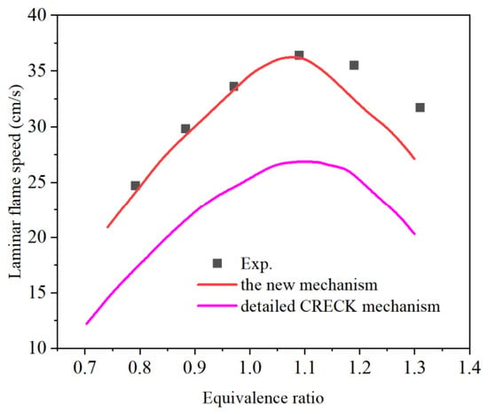
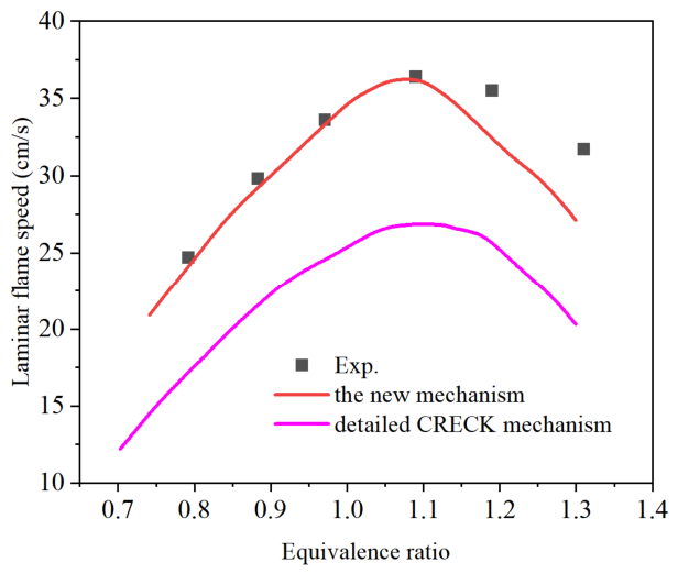
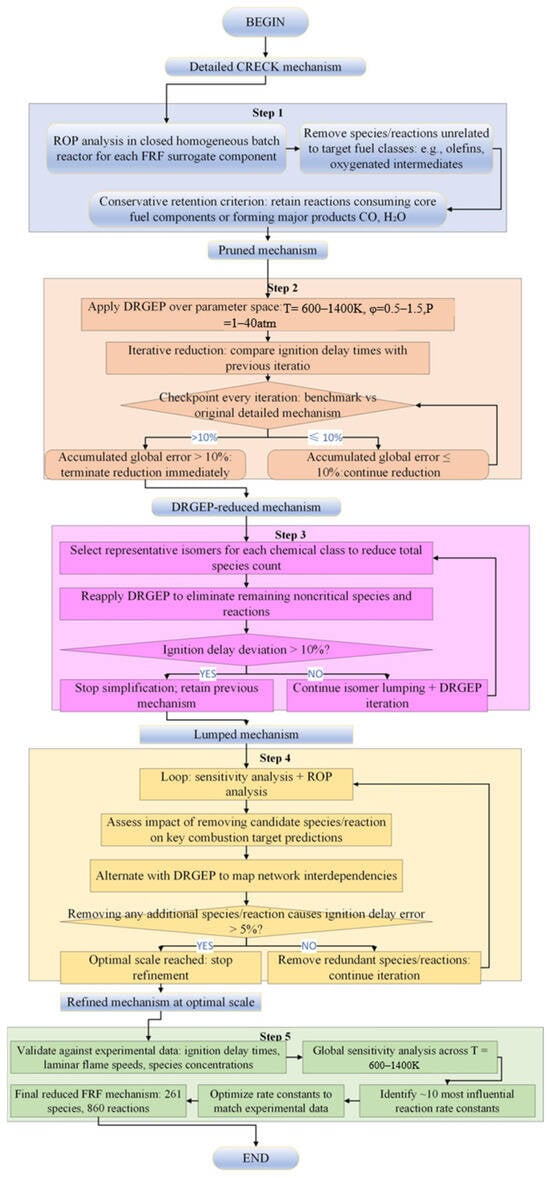
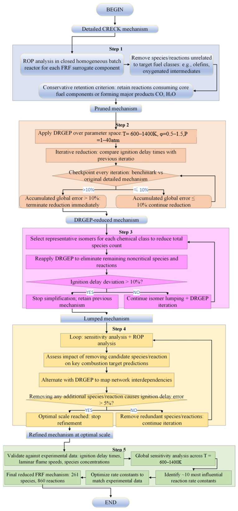
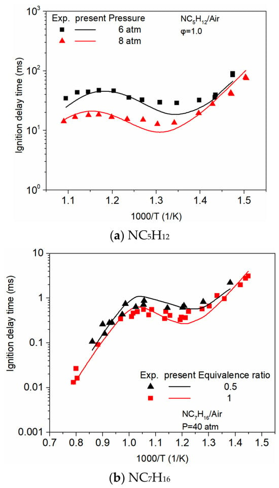
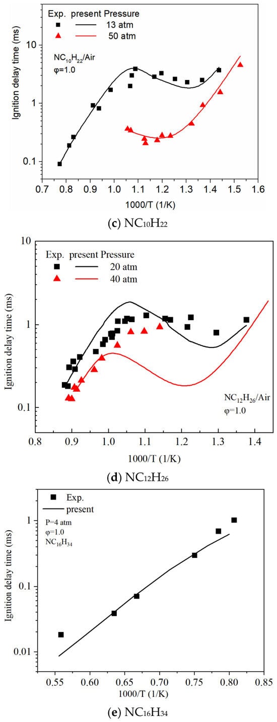
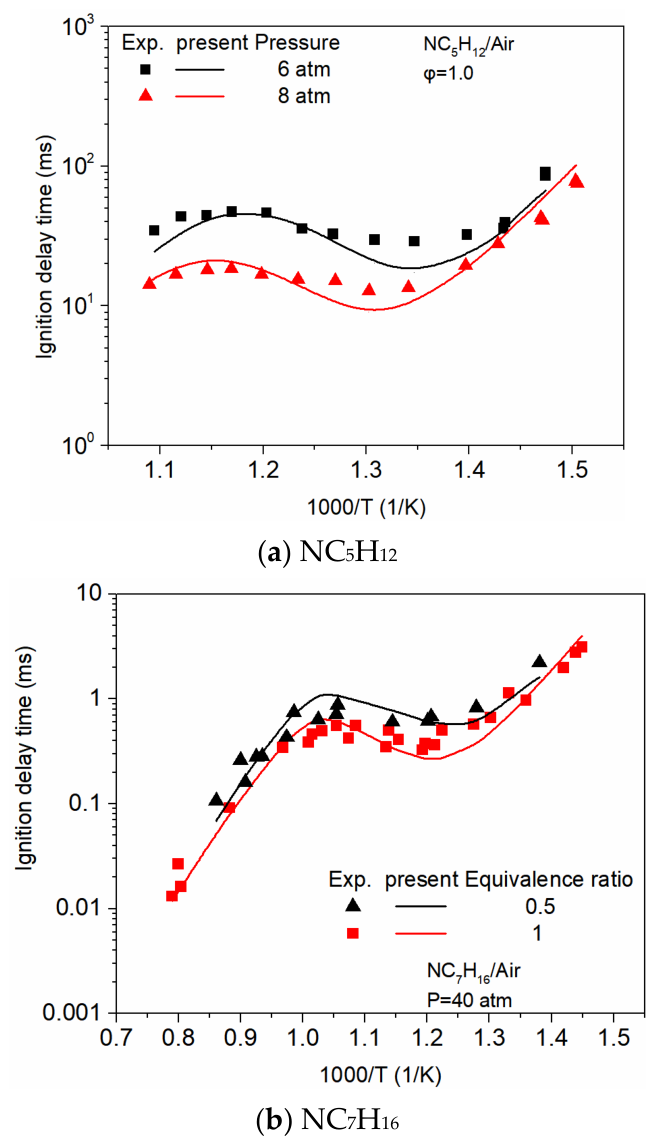
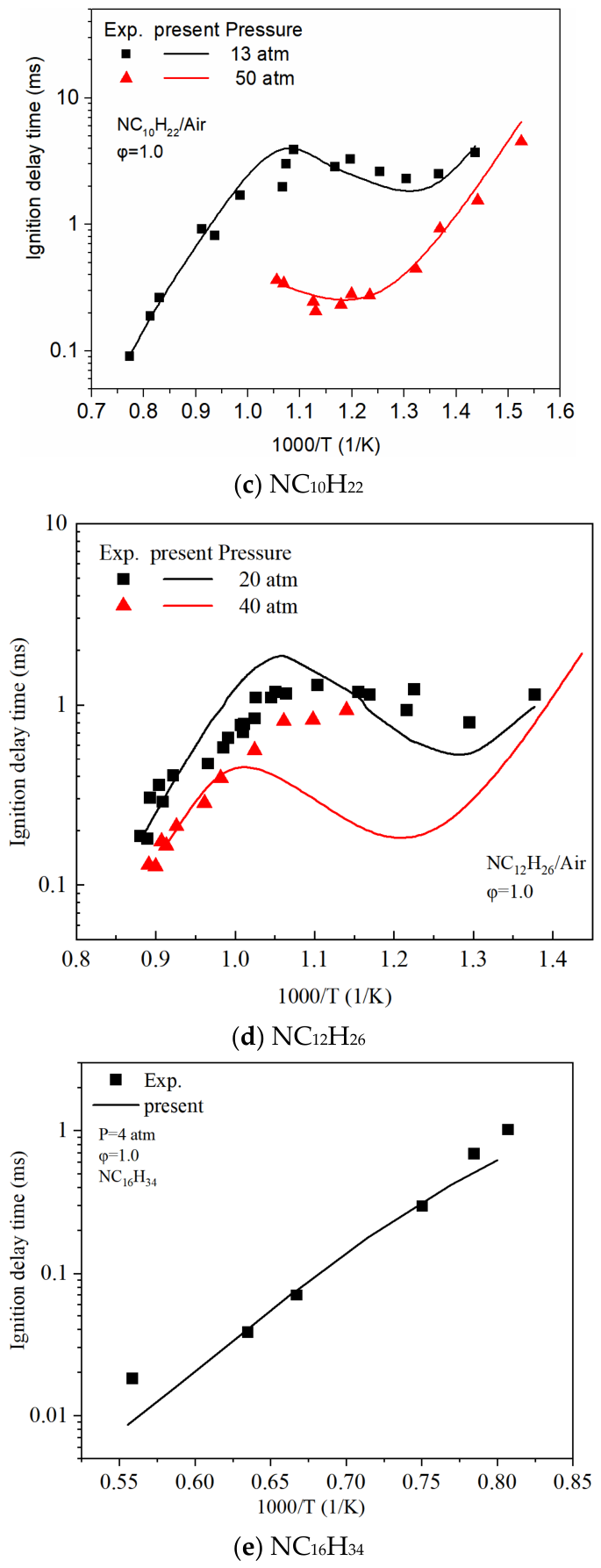
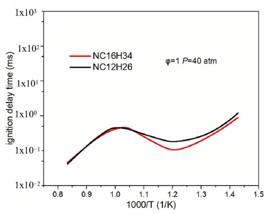
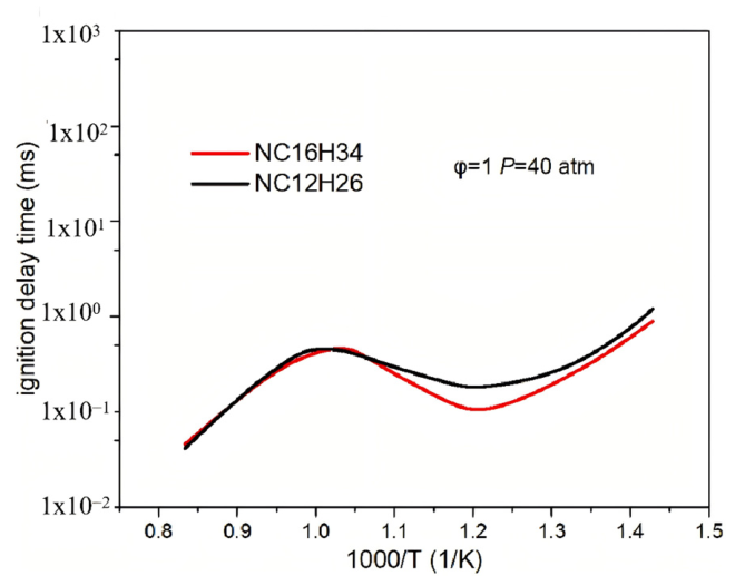
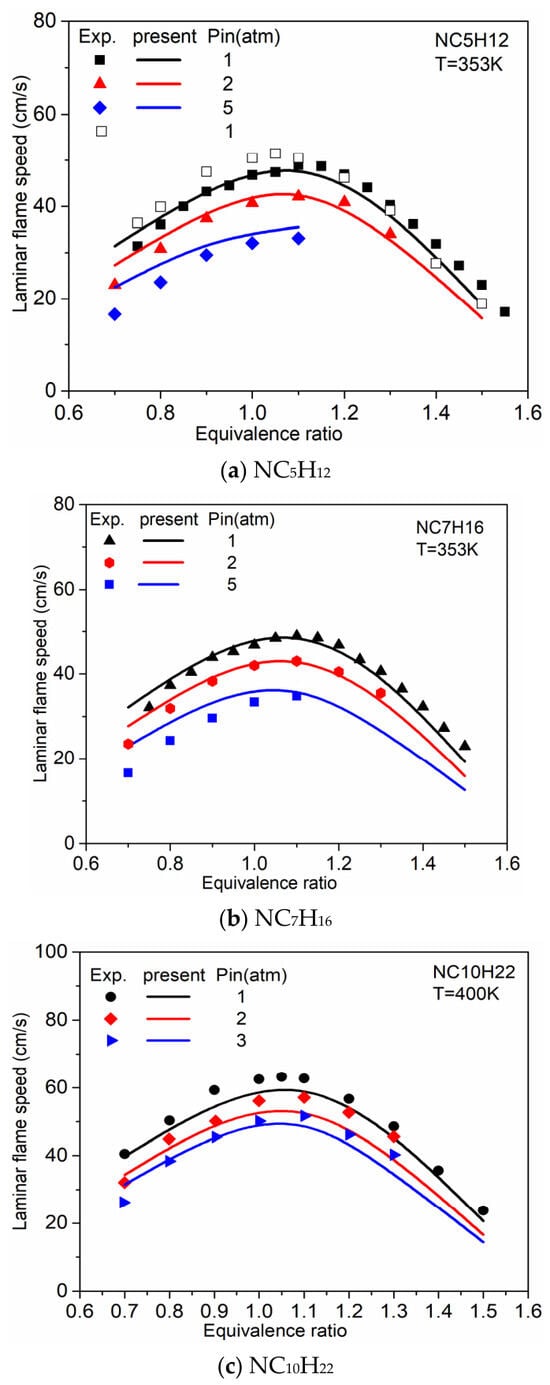
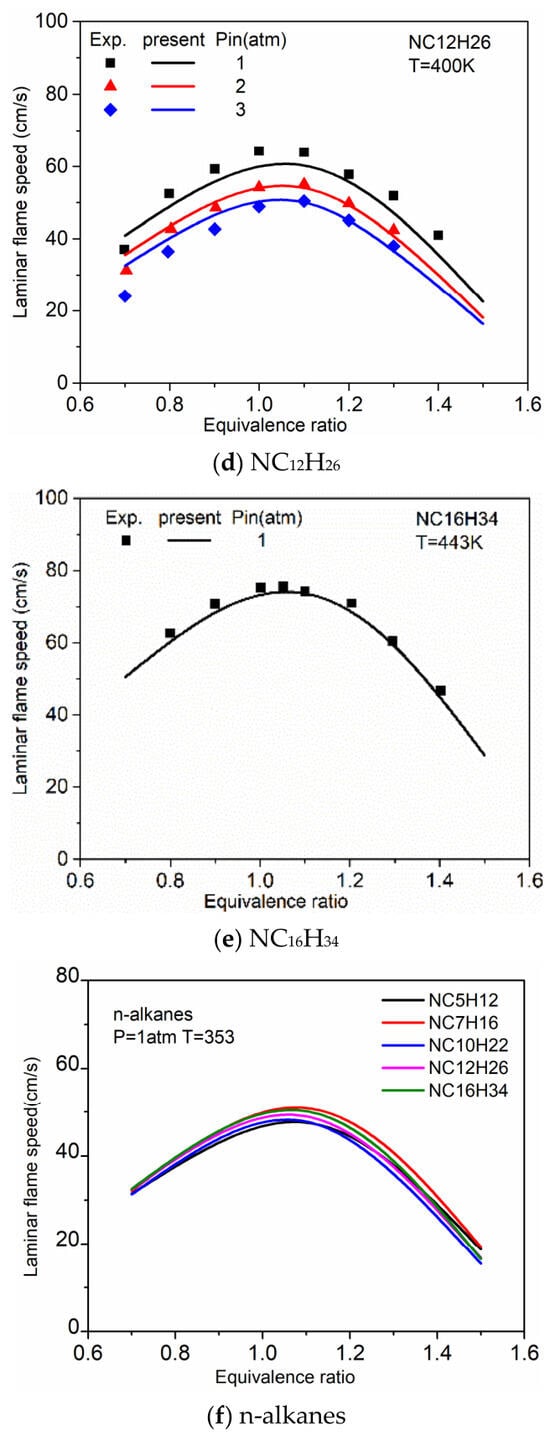
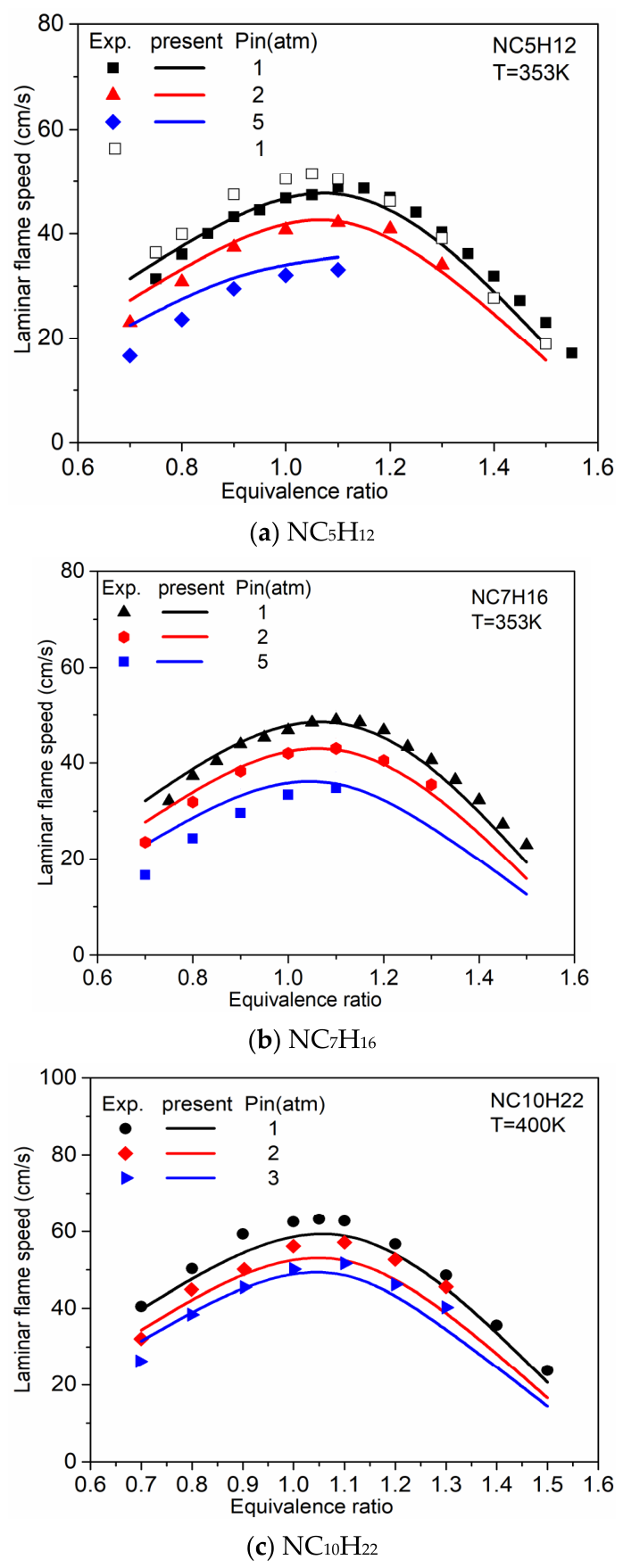
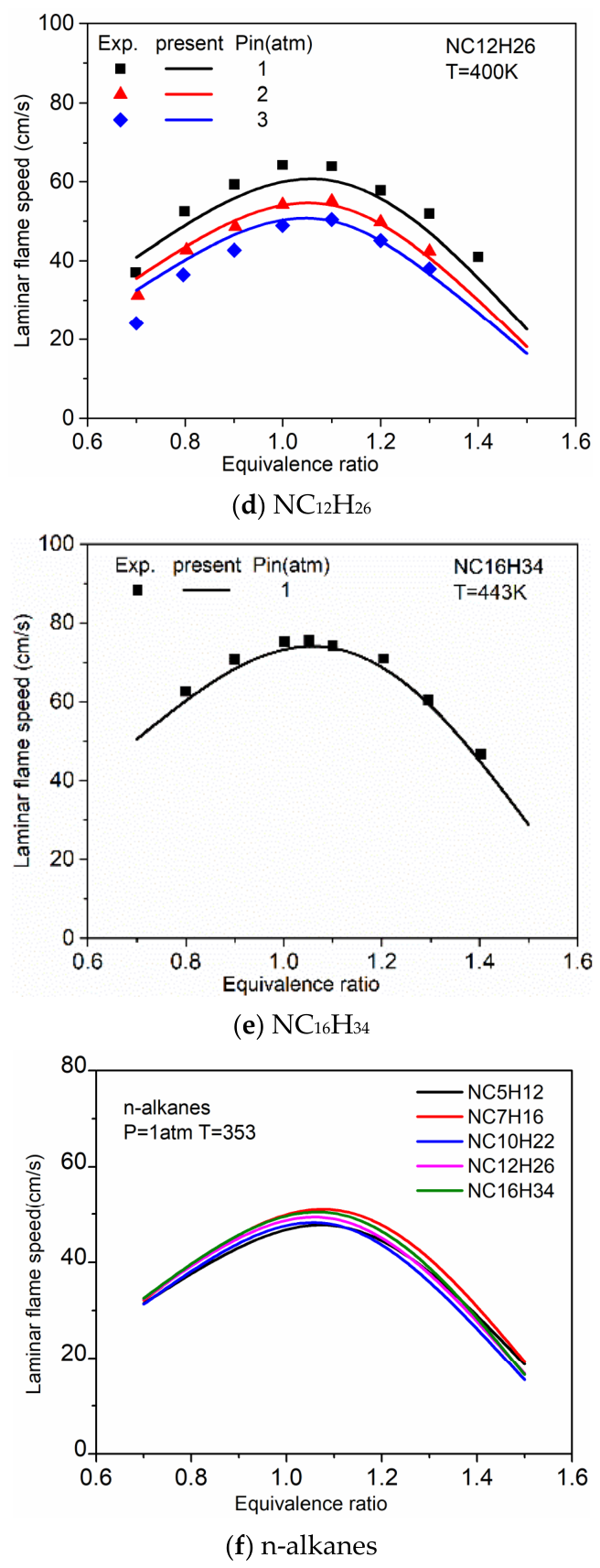
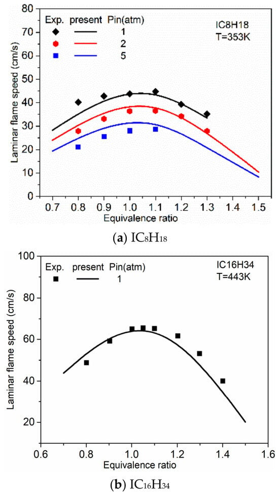
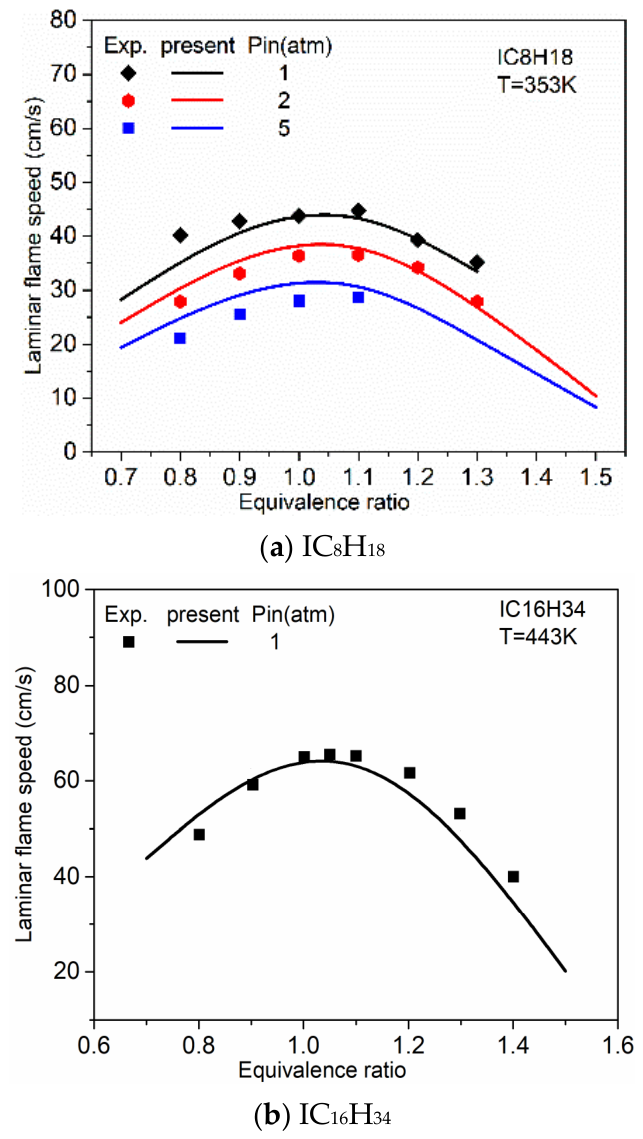
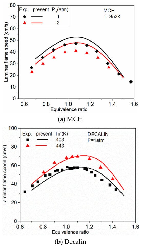
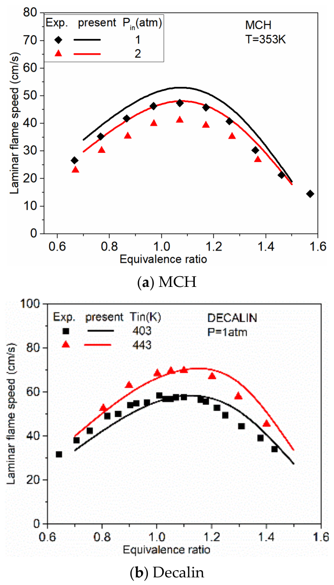
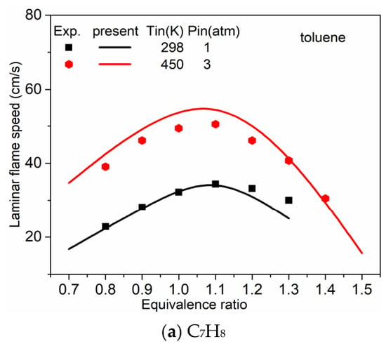
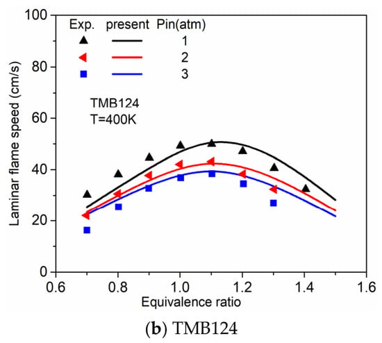
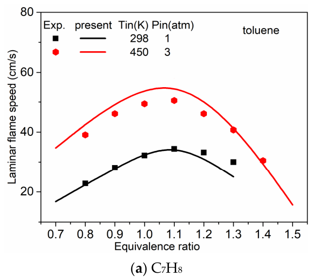
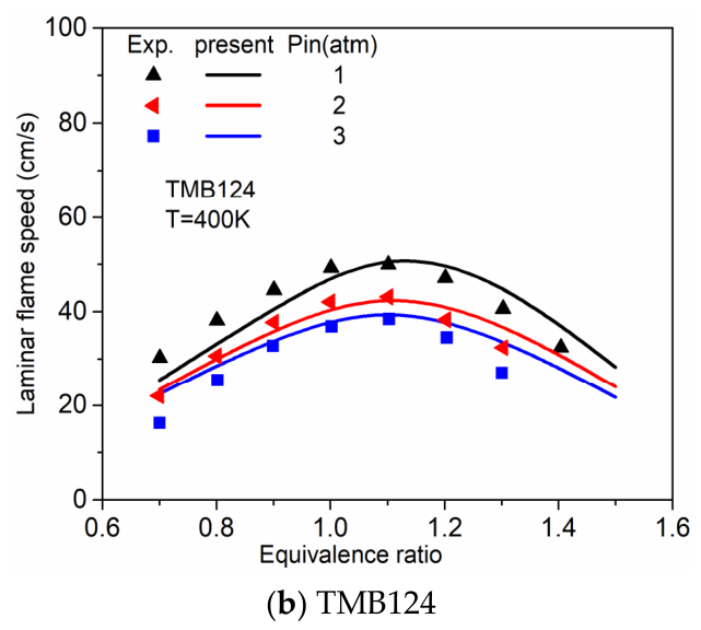
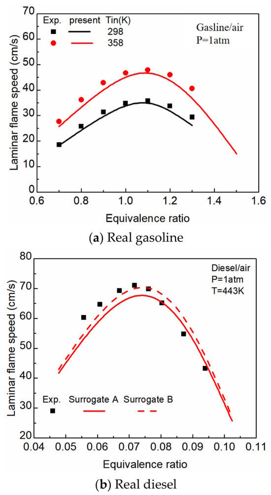
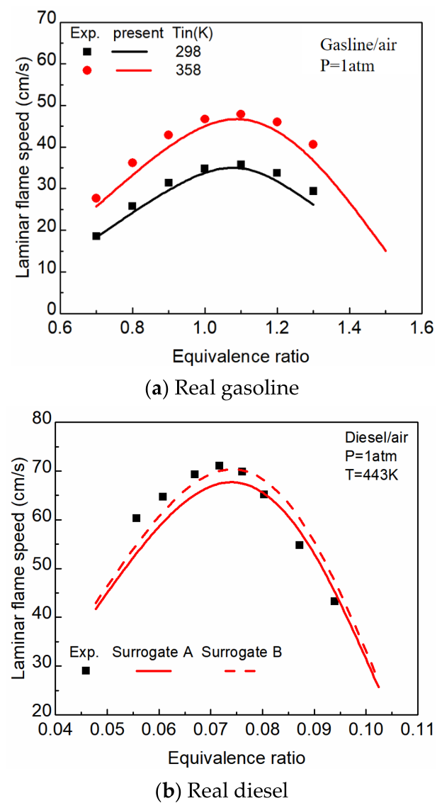
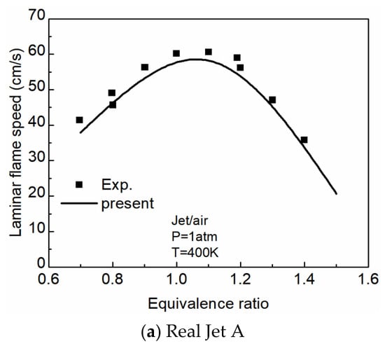
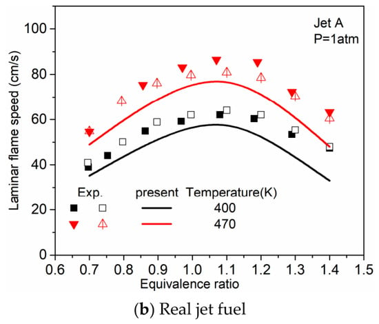
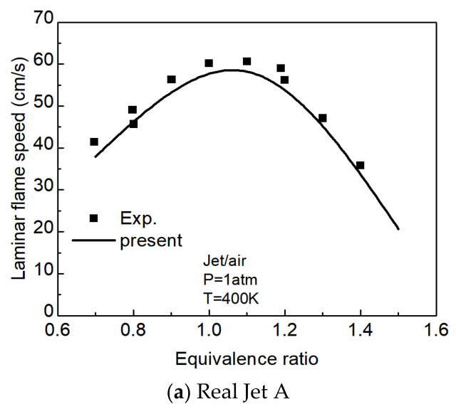
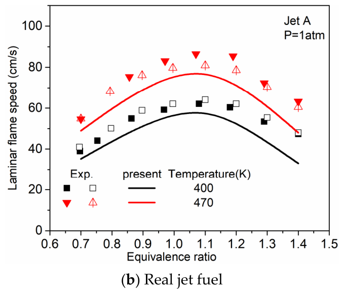
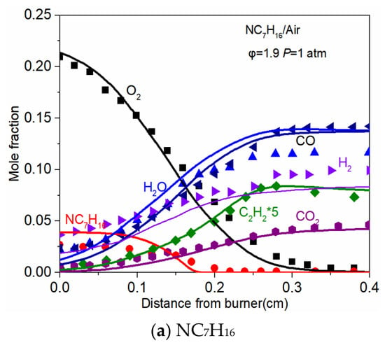
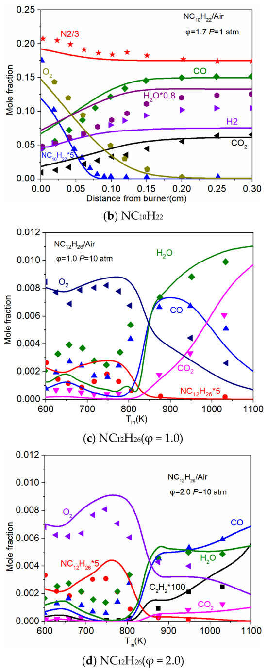
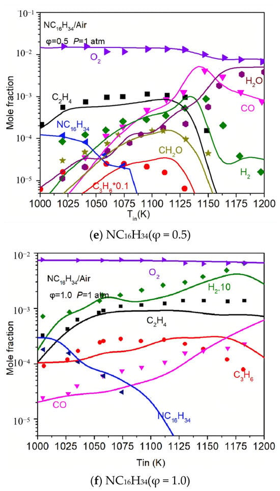
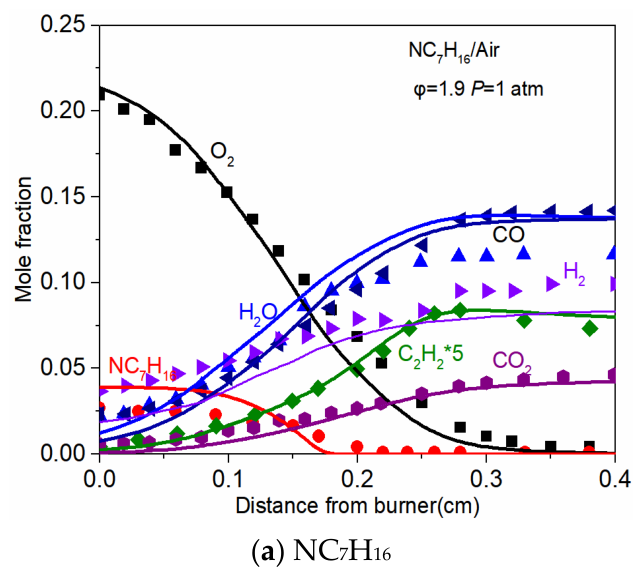
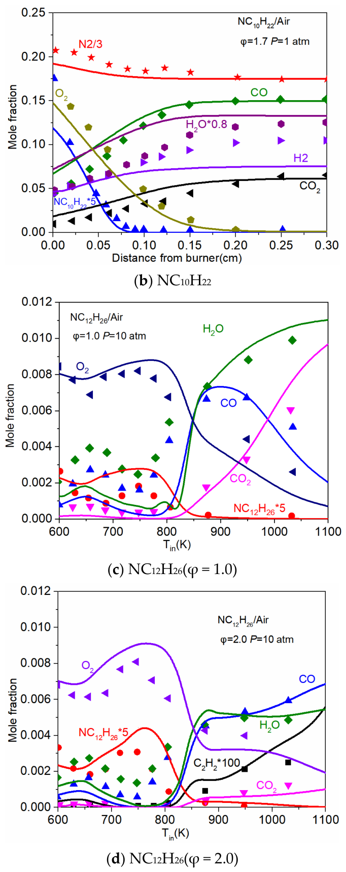
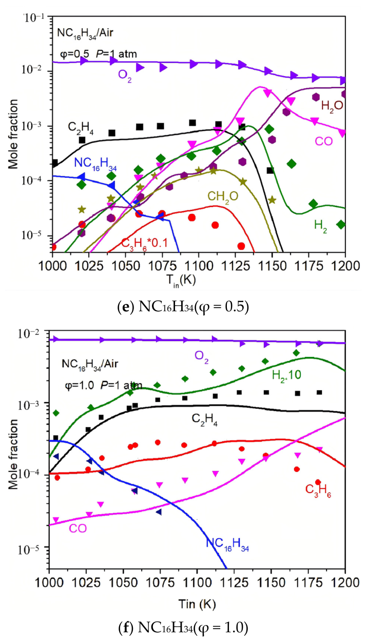
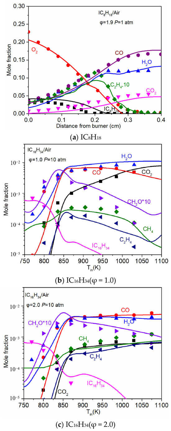
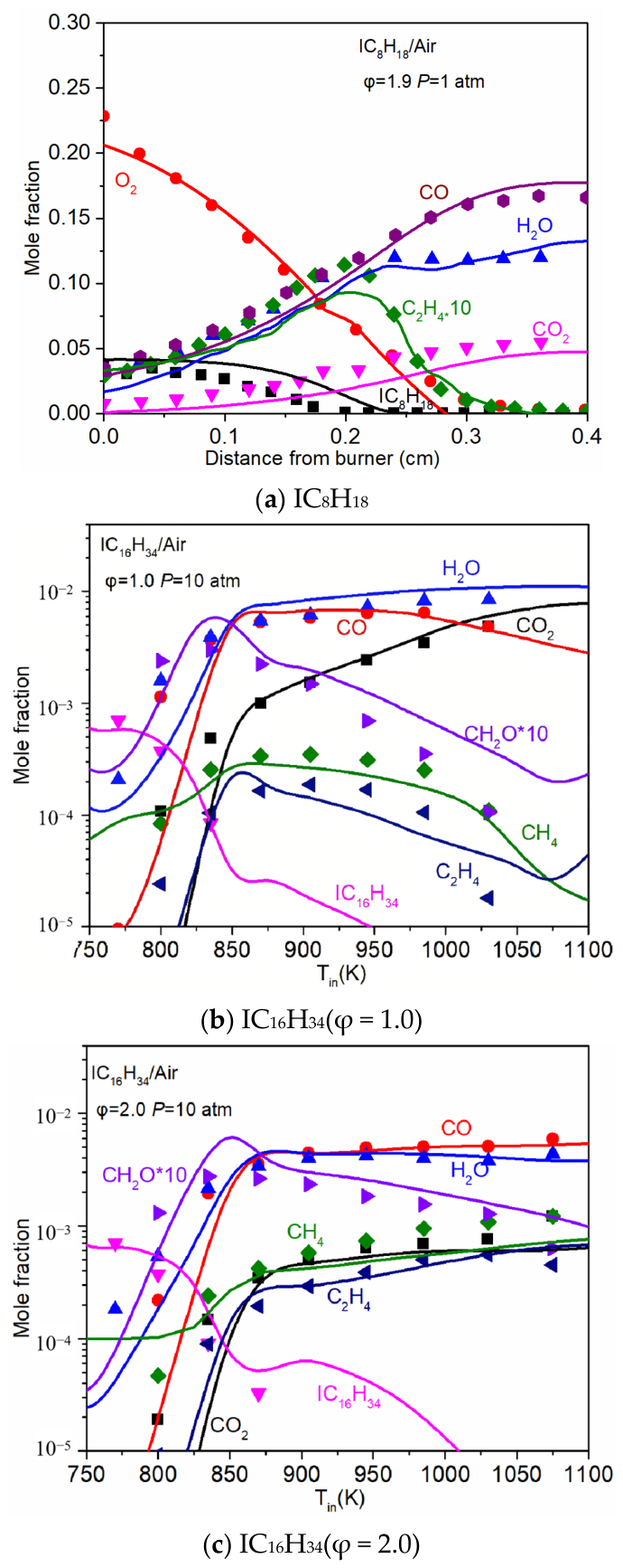
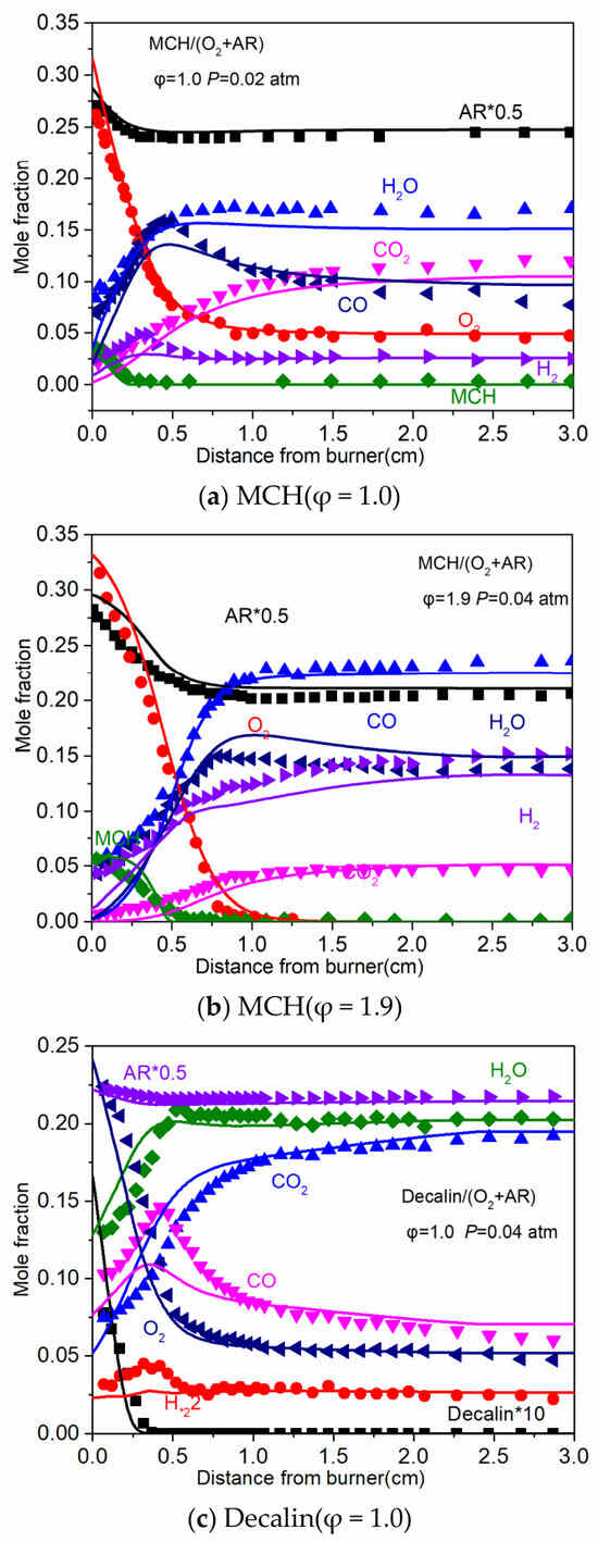
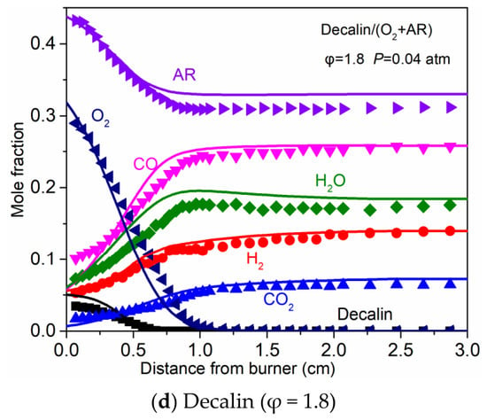
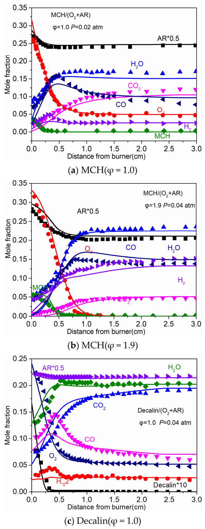
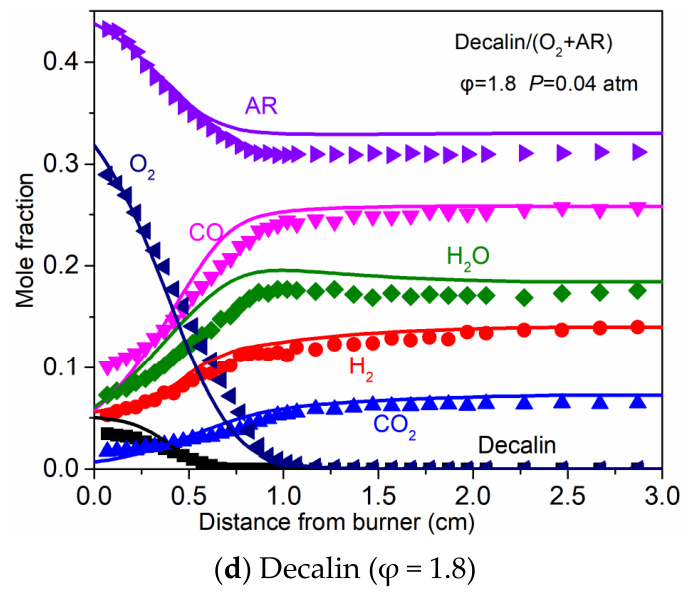
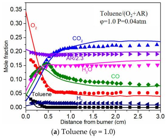
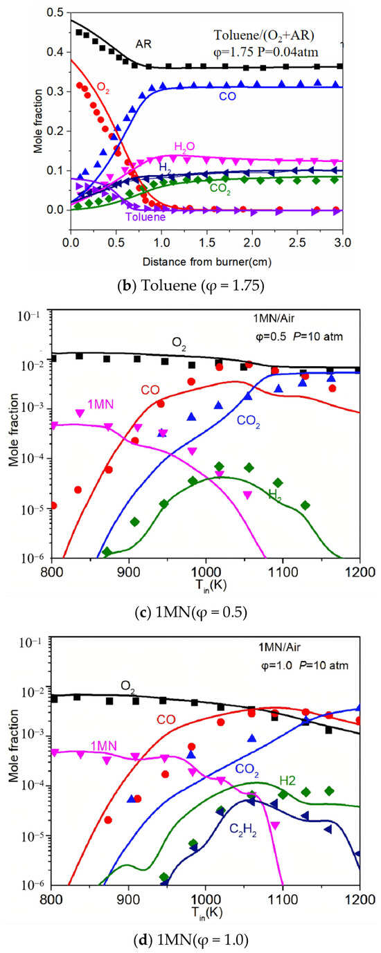
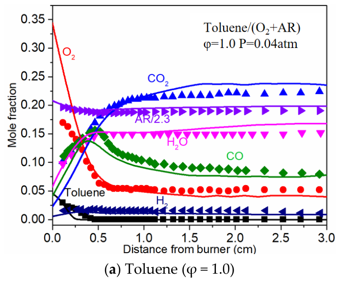
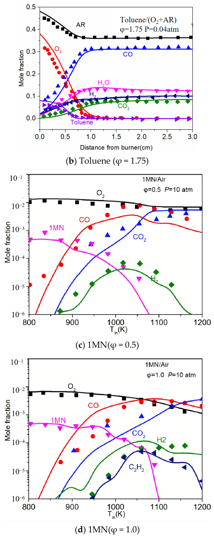
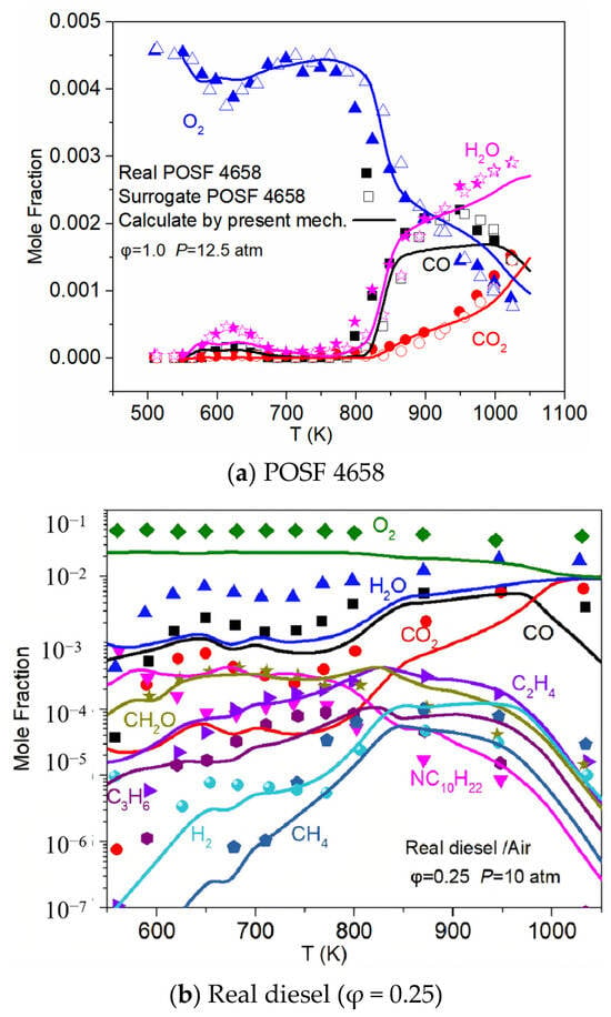
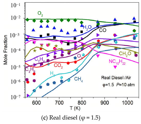
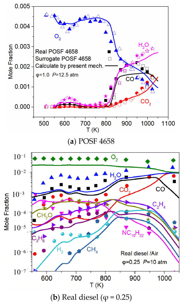
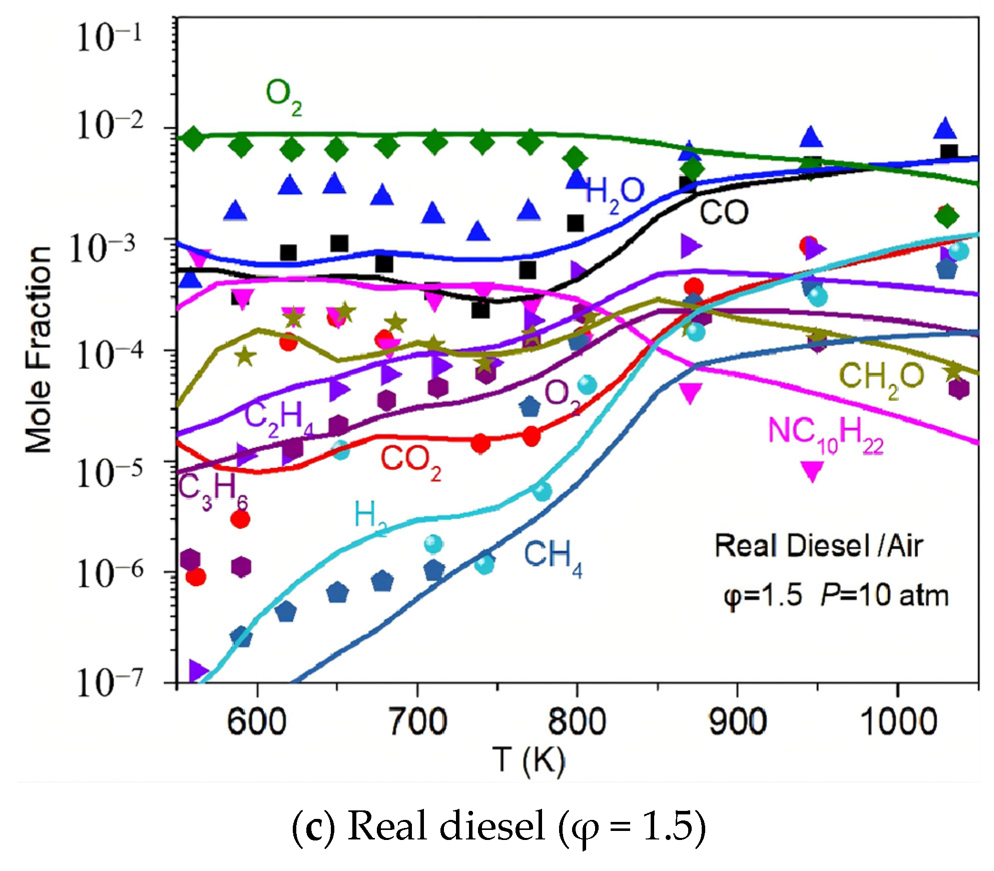
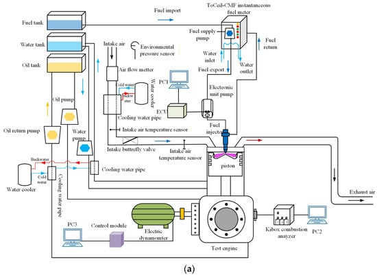
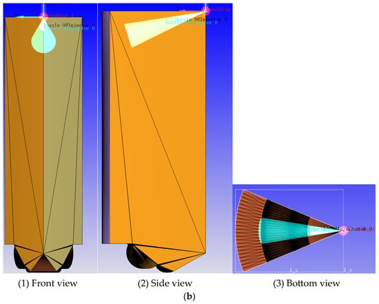
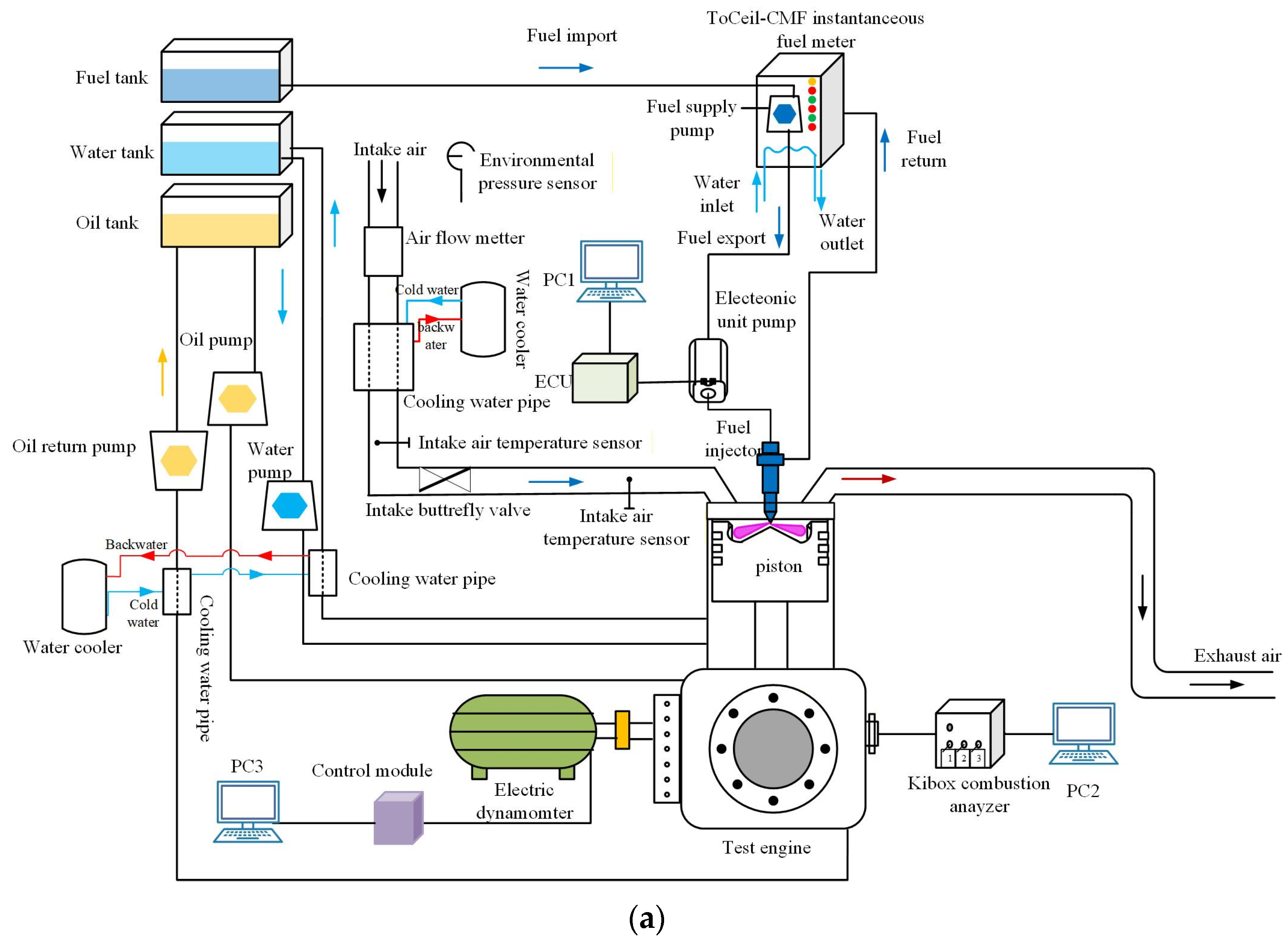
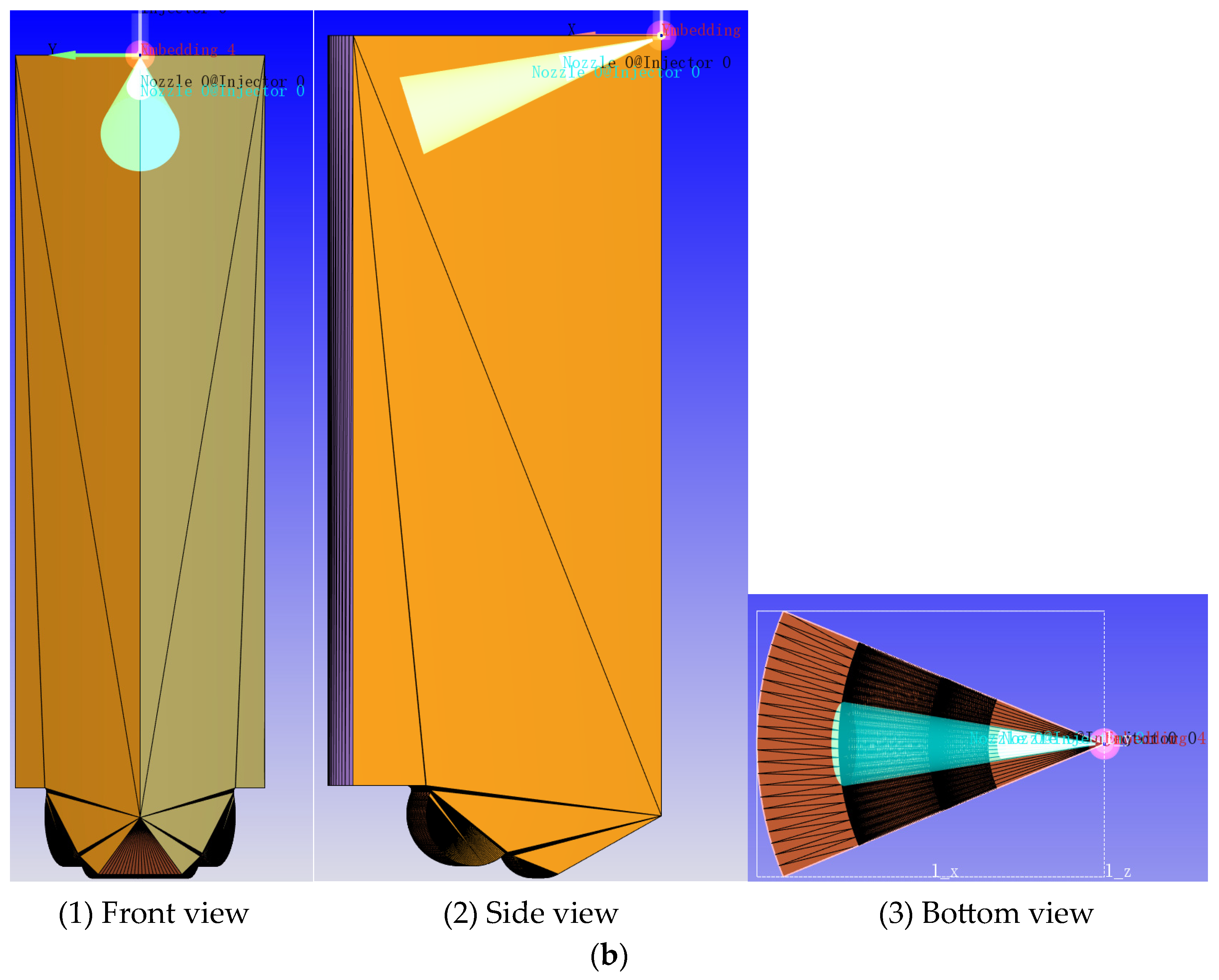
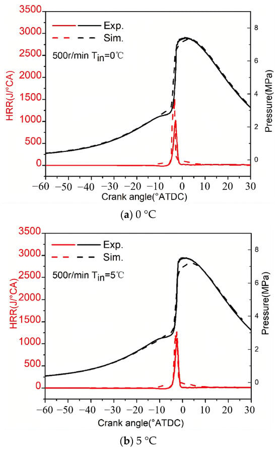
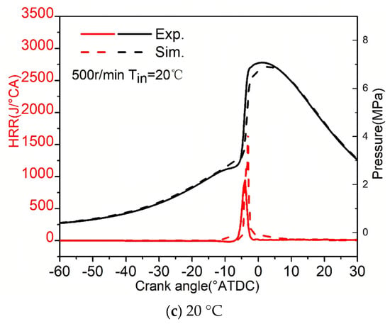
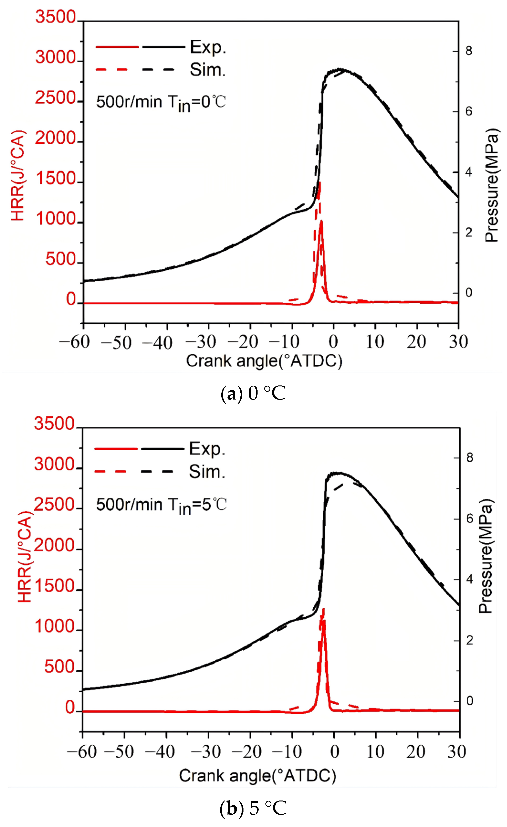
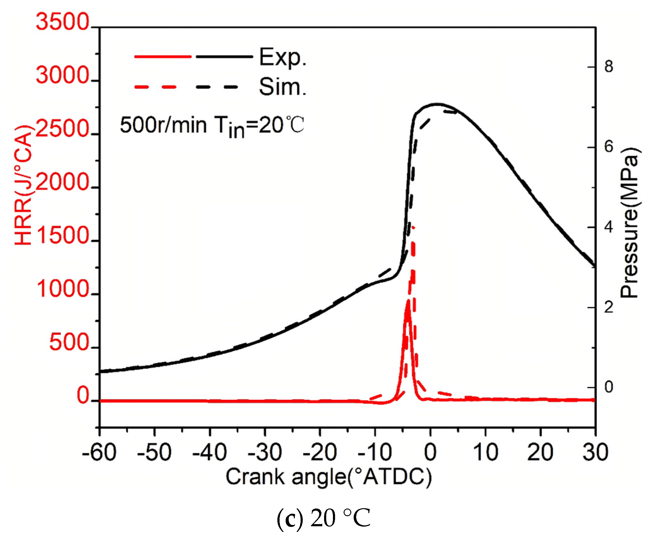
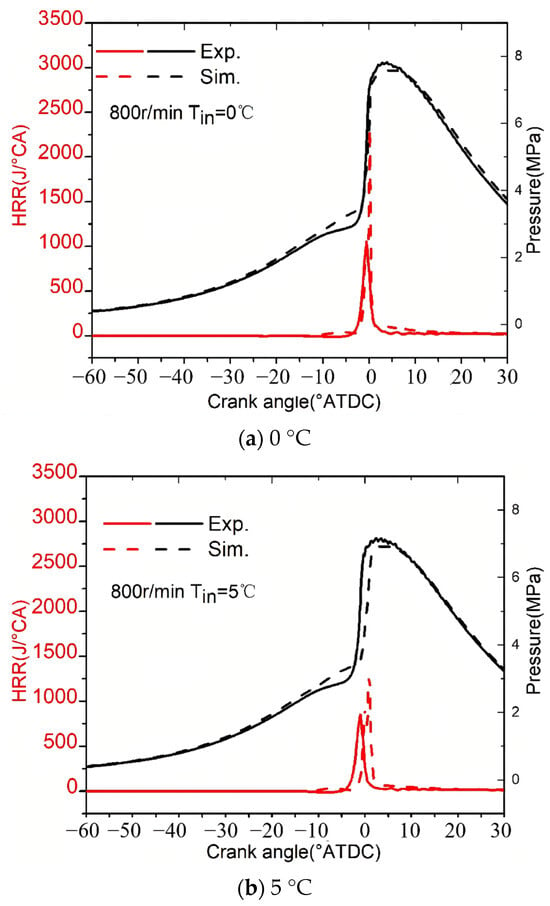
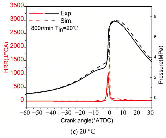
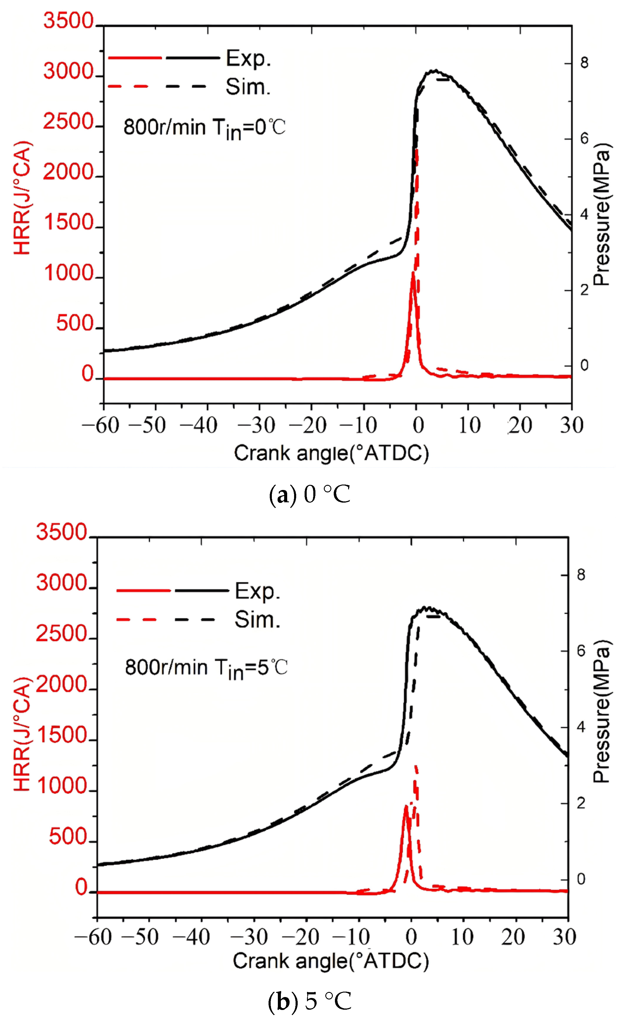
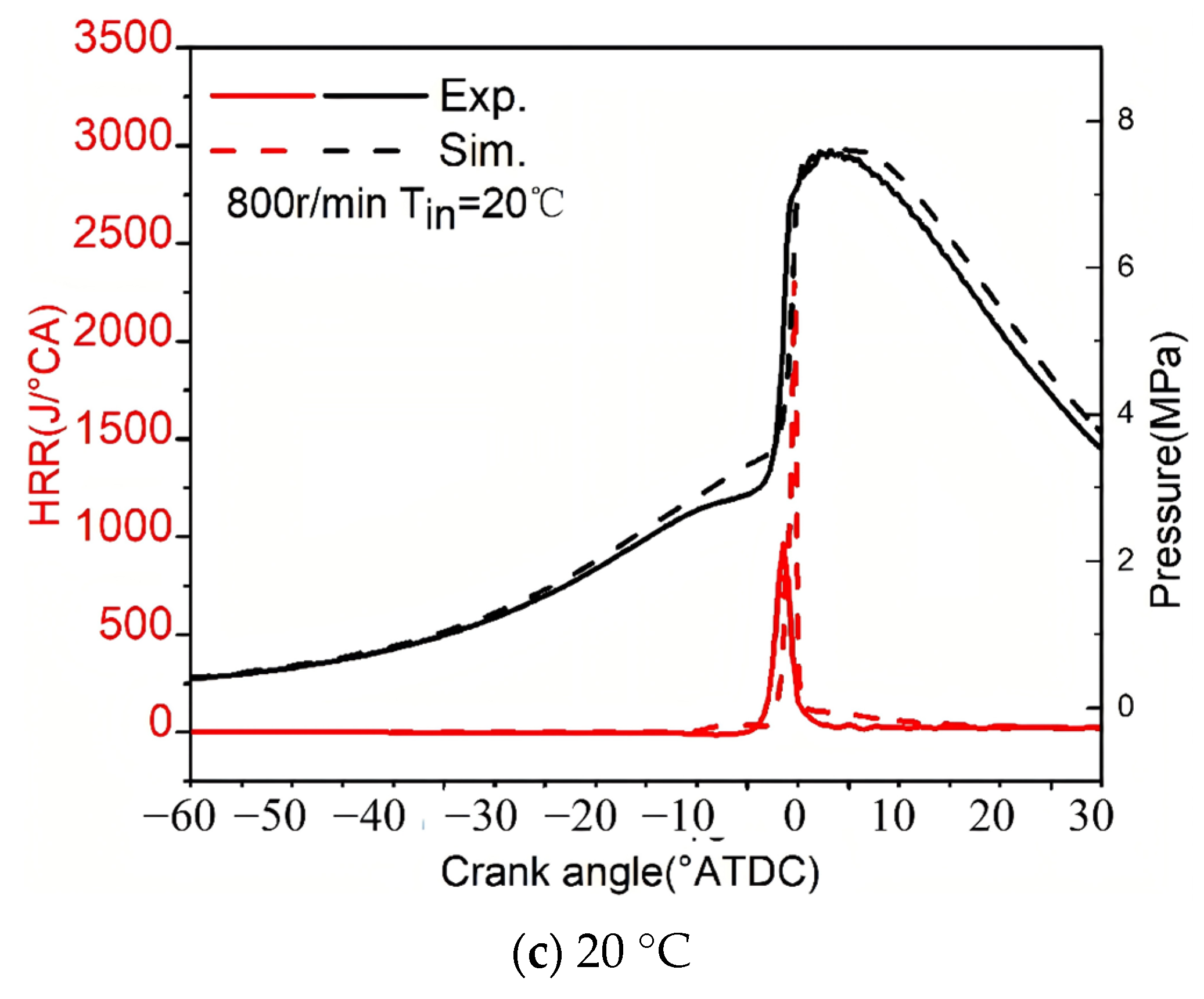

Disclaimer/Publisher’s Note: The statements, opinions and data contained in all publications are solely those of the individual author(s) and contributor(s) and not of MDPI and/or the editor(s). MDPI and/or the editor(s) disclaim responsibility for any injury to people or property resulting from any ideas, methods, instructions or products referred to in the content. |
© 2026 by the authors. Licensee MDPI, Basel, Switzerland. This article is an open access article distributed under the terms and conditions of the Creative Commons Attribution (CC BY) license.