


Abstract
Hydrogen is acknowledged as a clean and sustainable energy source due to the increasing demand for renewable energy sources. Photoelectrochemical (PEC) water splitting presents a viable approach for directly producing hydrogen from solar energy with negligible implications for the environment. However, regardless of the intensive studies over several years, a major hurdle to translating impressive laboratory-scale efficiency into robust, dependable, large-scale production of hydrogen is increasing competition from quickly advancing photovoltaic (PV)–based electrolysis technology. In parallel, Z-scheme or S-scheme artificial leaf catalyst systems mimicking photosynthesis are gaining ground in the research community. The performance and reliability of photo-electrocatalytic large-scale hydrogen production should be evaluated via pilot-scale and field studies, along with life cycle and economic studies. In the present manuscript, a comprehensive overview of technologies related to scalability is presented, with a focus on semiconductor materials and reactor design. In conclusion, problems and opportunities for future research on large-scale production technologies are presented.
1. Introduction
Hydrogen is the most abundant element in the world and a zero-emission energy source when it is used as a fuel, since it produces only water vapour. Nowadays, the production of hydrogen by photocatalysis, using light energy, is becoming more appealing [1]. According to the Global Hydrogen Review 2026 by the International Energy Agency [2], global hydrogen demand increased by nearly 3% in 2025, surpassing 100 Mt for the first time. China is the primary hydrogen user, accounting for 30% of global demand, while North America and the Middle East account for 16% and 15%, respectively. Unlike all major markets that experienced annual demand growth, Europe’s demand remained at the same level as in 2024. Experts forecast that, by 2030, global demand is likely to surpass 100 million tons, highlighting an urgent need for strategic planning and innovative solutions.
Photocatalytic (PC) and photo-electrocatalytic (PEC) hydrogen production are essential methods in the broader endeavour to convert fluctuating solar energy into storable chemical fuels [3,4,5]. Both methodologies aim to facilitate the water-splitting reaction by solar energy, although they diverge in the way they absorb light, in charge separation, and in catalysis. In photocatalytic systems, suspended or immobilised semiconductor particles directly link light absorption and catalytic turnover at their surfaces, usually within a single reactor.
In photo-electrocatalytic systems, one or more photoelectrodes within an electrochemical cell provide the necessary potential when illuminated, featuring separate anodic and cathodic sites, frequently accompanied by an applied bias. Despite extensive study over several decades, the conversion of promising laboratory-scale efficiency into reliable, large-scale hydrogen production continues to pose a significant barrier, intensified by the growing rivalry from rapidly developing photovoltaic (PV)–electrolysis systems [6].
From a scalability point of view, photocatalysis presents conceptual simplicity and minimal equipment complexity: slurries or immobilised films/sheets can theoretically function in cost-effective reactors without necessitating expensive membranes or complex balance-of-plant systems. The scaling up of photoreactors presents significant issues in terms of light distribution, mass transfer, catalyst recovery, and gas–solid–liquid management. As reactor dimensions expand, photon usage becomes progressively non-uniform, resulting in dark zones and diminished quantum yields unless carefully designed optical and hydrodynamic engineering is implemented. Addressing the efficient collection of hydrogen and oxygen, preventing explosive mixtures, and mitigating catalyst loss or deactivation due to aggregation, fouling, or photodegradation are significant challenges that must be resolved before realistic commercial deployment [7].
Conversely, PEC topologies are fundamentally modular and more akin to established electrochemical and photovoltaic technologies, which facilitate engineering scale-up and system integration. Photoelectrodes may be constructed as either planar or textured devices, incorporated into stacked cells, and combined with known gas handling, separation, and safety protocols. This configurational flexibility has resulted in remarkable device-level solar-to-hydrogen (STH) efficiencies in laboratory settings, particularly with tandem absorbers and meticulously designed catalyst–semiconductor interfaces [8,9,10,11]. High-performing PEC devices typically depend on intricate or expensive materials (e.g., III–V semiconductors, noble metal catalysts) and advanced deposition techniques, which raises concerns regarding capital expenditures, material accessibility, and long-term durability in realistic outdoor environments [12,13,14]. Furthermore, when assessed based on the levelised cost of hydrogen (LCOH), PEC systems must contend with PV–electrolysis designs that presently utilise gigawatt-scale PV manufacture and progressively standardised electrolyser technology [15,16], as well as photothermal catalytic H2 generation [17].
Recent advancements have concentrated on closing the divide between high-performance small-area demonstrators and practically scalable modules in both photocatalytic and photoelectrochemical methodologies. Photocatalysis encompasses the advancement of visible light-responsive, earth-abundant semiconductors and co-catalysts exhibiting enhanced stability; sophisticated reactor designs (e.g., fluidised beds, falling film, and micro-structured reactors) that maximise photon flux and mass transfer; and methodologies for catalyst immobilisation and recovery suitable for high throughput [18]. In PEC water splitting, the focus is on scalable photoabsorber platforms (including protected silicon and metal oxides), abundant HER/OER electrocatalysts, corrosion-resistant interlayers, and m2-scale modules that ensure uniform current density and dependable gas separation during prolonged operation [19,20]. Concurrent techno-economic evaluations increasingly emphasise that process simplicity, system longevity, and manufacturability are at least as critical as peak solar-to-hydrogen efficiency for the scalability and financial viability of solar hydrogen technologies [21,22].
In parallel, researchers seek solutions to design complicated photocatalysts structures, so-called artificial leaves that mimic photosynthesis, as a viable alternative to producing H2 through solar-to-chemical conversion processes. Such systems are standalone, wireless photoelectrochemical modules that integrate light absorbers and catalysts directly into a single unit, most often in Z-scheme or S-scheme configurations. Much research is still needed to improve these technologies and bring them to an industrial level [23].
This review seeks to critically evaluate the status of photocatalytic and photo-electrocatalytic hydrogen production, with a specific focus on the scalability of the processes. Following a brief description of the core principles of both methodologies, we analyse current advancements in materials and devices aimed at extensive, durable performance. We subsequently examine reactor engineering, gas management, and system integration factors that dictate the progression from laboratory to pilot and industrial scales. We emphasise recent advancements, encompassing novel catalyst and photoabsorber systems, scalable fabrication methodologies, reactor designs, and techno-economic assessments. By comparing these advancements with the present course of PV–electrolysis, we seek to elucidate the authentic advantages of PC and PEC pathways, identify the constraints hindering their implementation, and determine the most promising research avenues for achieving competitive, scalable solar hydrogen production.
In conclusion, the added value of this work is to provide a roadmap for upscaling efficiently solar-driven hydrogen production as a result of in-depth assessment of the current state of the art of PC and PEC hydrogen production technologies. Material and reactor design are evaluated both technologically and financially. This approach allows the identification of key scientific and engineering barriers and highlights the most promising solutions for scalable implementation of these technologies.
2. Materials
2.1. Photocatalysts
For the time being, solar-to-hydrogen production using photocatalysis is a prominent research topic and a vital sector with substantial strategic and academic value; therefore, comprehensive studies have concentrated on augmenting catalyst efficacy, refining reaction selectivity, and optimising solar energy consumption. Currently, methodical studies of photocatalytic systems have produced substantial advancements, with remarkable inventions arising from interdisciplinary investigators [24]. Recent studies have brought the development of photocatalytic materials to a high level by applying different sophisticated preparation methods, such as sonochemical exfoliation [11,24], flame spray pyrolysis [25], supercritical antisolvent (SAS) precipitation [26], and multi-photon lithography [27]. Nevertheless, traditional chemical routes, including thermal polycondensation [28], solid state reactions [29,30], liquid phase methods including hydrothermal/solvothermal [31,32,33], sol–gel [34], co-precipitation methods [35], liquid deposition methods, and solution combustion [36,37], advanced synthesis techniques including electrospinning [38], and gas phase methods [39] including physical vapour deposition (PVD), chemical vapour deposition (CVD), and molecular beam epitaxy (MBE) aim to design highly effective heterostructures that exhibit enhanced photocatalytic behaviour.
Based on their composition and structure, photocatalysts for hydrogen (H2) production can be classified into the following categories or a combination of them: inorganic salt [40], metal-based at the micro- and nanoscale, metal-based doped with other metallic elements to tailor energy band gaps and manipulate overall photocatalytic efficiency [25,41,42,43,44,45,46], metal–organic frameworks (MOFs) [47,48], covalent organic frameworks (COF) [49,50], carbon-based [51,52,53,54,55,56,57] perovskites [58,59,60], composites and heterostructures [26,52,53,54,55,56,58,61,62,63,64,65,66,67], organic molecules decorated with noble metals [68], and hydrogen-bonded organic frameworks (HOFs) [69].
A single photocatalyst utilising one-step photoexcitation represents the most straightforward approach for water splitting. Such a photocatalyst must meet the thermodynamic requirements for both the reduction of water to H2 and the oxidation of water to O2. Alternatively, heterojunctions which employ two photocatalysts offer another strategy for water splitting. In Type II and Z-scheme configurations, each photocatalyst is required to facilitate either H2 or O2 evolution, thereby expanding the range of suitable photocatalyst materials [70,71,72,73]. Possible heterojunctions are presented in Figure 1. In the Type I configuration (Figure 1a), both the valence band (VB) and the conduction band (CB) of semiconductor II with the smallest energy bandgap are enclosed within the larger energy bandgaps of semiconductor I. Upon irradiation with sufficient energy, electron–hole pairs are photogenerated, and, due to the potential difference in the band edges, the e− are transferred and accumulated in the CB of semiconductor II (with the lowest energy), while h+ are accumulated in the VB of the same semiconductor with the highest energy. Since the charge carriers accumulate in the same semiconductor, there is no charge separation, and they recombine, reducing photocatalytic efficiency. In a Type II heterojunction, the energy band gaps of the two semiconductors are not confined, but are staggered between semiconductors I and II. The different Fermi levels between semiconductors in contact trigger charge transfer to reach equilibrium, forming an interfacial electric field which bends the energy bands upward and downward, driving e− and h+ to migrate in opposite directions. Therefore, the Type II configuration enhances electron–hole spatial separation, prolonging their lifetime and enabling the production of H2 and O2 in different semiconductors. In Type III heterojunctions (also called broken), bandgaps of the two semiconductors are well separated, and no charge separation and transfer occur. Therefore, such configurations are rarely applied for photocatalysis [74,75].
Figure 1.
Schematic energy band diagram of three different types of heterojunctions in a typical semiconductor hybrid nanocomposite: (a) Type I heterojunction, (b) Type II heterojunction, and (c) Type III heterojunction. A and D denote electron acceptor and electron donor, respectively (reprinted with permission from [74]).
A Z-scheme heterojunction (Figure 2) is designed on the principle of photosynthesis and therefore mimics photosynthesis in plants. Both photocatalysts are excited by the incident light, forming electron–hole pairs. Photogenerated e− in photocatalyst II (with the less negative CB edge) interacts and recombines with h+ in the less positive VB edge of photocatalyst I; thus, the remaining e− stay in the CB of photocatalyst I, and the h+ remain in the VB of photocatalyst II. This process achieves spatial separation of e− and h+, prolonging their lifetimes, and therefore the system has strong redox ability and exhibits increased light harvesting [71,74,76,77]. There are two types of Z-scheme heterojunctions: one with the absence of an e− mediator (conductor) (Figure 2a) and the other with the assistance of an electron mediator. This intermediate conductor is employed to facilitate electron transportation from photocatalyst II to photocatalyst I [74].
Figure 2.
Schematic illustration of the transfer of photoinduced charge carriers for various types of heterojunction nanocomposites: (a) semiconductor–semiconductor Z-scheme heterojunction, (b) semiconductor–conductor–semiconductor Z-scheme heterojunction, (c) Schottky junction of metal/g-C3N4 nanohybrids, (d) SPR effect of noble metal/g-C3N4 nanohybrids, (e) CNT/g-C3N4 heterojunction, and (f) graphene/g-C3N4 heterojunction. A, D, and Ef denote electron acceptor, electron donor, and Fermi level, respectively (reprinted with permission from [74]).
In a Schottky heterojunction (Figure 2c), e− flow from the semiconductor to the metal until equilibrium of the Fermi levels is reached. Thus, a Schottky barrier is formed that hinders e− transfer from metal to semiconductor, forming a space charge region (or depletion layer) at the interface of the metal/semiconductor (here g-C3N4) interface. An interfacial electric field is created due to the charge transfer between the metal and the semiconductor that continuously shifts the semiconductor band edges, resulting in upward band bending and the presence of e− in the metal and h+ in the semiconductor [74,78,79].
In the case of noble metal heterojunctions (Au, Ag), strong visible light absorption causes localised surface plasmon resonance (LSPR) (Figure 2d). The free electrons in noble metals interact with the photons of the incident light, triggering collective oscillations and surface plasmons. Plasmons then dissipate their energy by exciting energetic electrons (“hot electrons”) that are transferred to the CB of the semiconductor (here g-C3N4), participating in reduction reactions, while h+ left in the semiconductor can participate in oxidation reactions [74,80].
Carbonaceous nanomaterials with π-conjugated structures, such as CNΤs and graphene, are effective co-catalysts. As depicted in Figure 2d,f, a carbon co-catalyst can readily accept photoinduced electrons through its intimate interface with the semiconductor (here g-C3N4), inhibiting the recombination of the photogenerated electron–hole pairs and behaving as an excellent reduction medium [74].
When the CB and Fermi levels of the oxidative photocatalyst are higher than those of the reduction photocatalyst, an S-scheme heterojunction is formed (Figure 3). In this configuration, e− located on the CB of the oxidative photocatalyst interact with the h+ of the valence band of the reduction photocatalyst and recombine. Therefore, efficient charge separation and maximised redox capabilities are achieved. The free e− on the CB of the reduction photocatalyst participate in reduction reactions, while the h+ on the VB of the oxidative photocatalyst cause oxidation reactions [81,82,83].
Figure 3.
Schematic representation of the MB sunlight catalytic degradation mechanism over the BZFG NCs (reprinted with permission from [83]).
Although heterojunction photocatalysts improve photocatalytic efficiency by enhancing light absorption capability, inhibiting charge–carrier recombination and facilitating charge transport to the catalytic surface, their performance is governed by various external factors (electrolyte pH level and ionic strength, outdoor light fluctuations, long-term cycling, etc.) [84,85,86,87]. Type II heterojunctions suffer from low redox energy due to relaxation phenomena, trap-induced instability at the interface, and poor outdoor performance. Direct Z-scheme heterojunctions, while having high charge carrier separation efficiency and preserving redox strength, are sensitive to interfacial contamination and delamination [88,89] and have long-term stability issues [85]. S-scheme heterojunctions exhibit highly robust redox power and are very stable and resistant to variable illumination. However, their performance is contingent upon controlled defect density: insufficient defects limit effectiveness, while excessive defects flatten band bending [89].
To address these challenges, researchers are focusing on improving charge generation, separation, and migration. They are exploring the creation of multiple heterojunctions, such as double or triple Type II, Z-scheme, S-scheme, and even combinations of these (and with other types, such as Schottky). Developing such complex heterostructures requires the use of machine learning and AI techniques to optimise synthesis parameters and predict the best material combinations for large-scale production [85,90].
The literature suggests that the potential scalability of these systems is attributed to specific heterojunctions, as explained below.
A novel Type-II 2D/2D PDTBT/CN polymer heterojunction has been developed using 2D poly(4,7-dithienyl-2,1,3-benzothiadiazole) (PDTBT), which incorporates N…S intramolecular conformational locks to suppress non-radiative recombination, along with 2D graphitic carbon nitride (CN). The resulting 25PDTBT/CN heterojunction (with 3 wt% Pt) displays significantly enhanced hydrogen evolution activity, achieving 17.09 mmol g−1 h−1 under visible/near-infrared light, with good cycling stability over 30 h. The remarkable photocatalytic performance is attributed to the effective suppression of exciton–phonon coupling facilitated by the N…S intramolecular conformational locks, as well as efficient photogenerated carrier transfer through van der Waals forces, specifically π–π interactions and intermolecular C…S/N…S interactions between PDTBT and CN [75].
A direct dual-Z-scheme heterojunction of CdS/W18O49/g-C3N4 nanocomposites has been fabricated, exhibiting superb stability and enhanced H2 production (11.6 mmol g−1 h−1) under simulated solar light conditions, without the need for any sacrificial agent. In this heterojunction, the photogenerated electrons in the CB of W18O49 migrate to the VB of CdS and g-C3N4 to recombine with the photogenerated holes, promoting the photocatalytic reduction reaction by the photoinduced electrons of CdS and g-C3N4 [91].
An outdoor setup of 692.5 cm2 halide perovskite photocatalytic system modules has been designed. This system features five tandem units arranged in series and is based on a Z-scheme heterojunction of MoSe2-loaded CH(NH2)2PbBr3-xIx. It utilises a redox mediator I3−/I−, which facilitates separation of the produced H2 and O2 gases. The system is capable of producing 105 mL of H2 per hour, achieving an average solar-to-hydrogen conversion efficiency of 1.21% during a week-long test conducted under natural sunlight conditions [58].
A dual-cocatalyst configuration of an S-doped g-C3N4/CoTe composite with a Schottky junction exhibited an outstanding hydrogen generation rate of 10.6 mmol g−1 h−1 and excellent stability in direct sunlight. The mechanism relies on electron depletion in g-C3N4 and electron accumulation in CoTe. Scaled-up testing demonstrated a consistent H2 evolution rate of 0.5 mL/h, underscoring effective photon utilisation and system robustness [56].
A more efficient Z-scheme heterojunction has been developed that effectively reduces loss of excitons due to recombination during their migration. This system is based on a hydrogen-bonded organic framework, 1,3,6,8-tetrakis(p-benzoic acid)pyrene (HOF-H4TBAPy). Its structure features hydrophilic one-dimensional micropore channels that allow photogenerated excitons to transfer to the inner surfaces of adjacent micropores and dissociate, instead of migrating over longer distances to the crystal plane. Based on this concept, a scalable flat-plate reactor has been constructed. This reactor can produce more than 1 mol H2 per m2 of catalyst loaded on cellulosic fibre, using a 0.5 m2 panel, in response to 9 h of simulated sunlight irradiation [69].
A novel S-scheme photocatalyst has been developed using a 2D/2D mesoporous BiVO4 on a crystalline carbon nitride (CCN). This design effectively suppresses charge recombination while maintaining excellent redox capabilities. The mesoporous structure of BiVO4 significantly increases the specific surface area of the BiVO4/CCN heterojunction, providing numerous active sites for photocatalytic reactions. This configuration allows for the simultaneous processing of wastewater and the generation of renewable hydrogen at a rate of 14.7 mmol g−1 h−1 [82].
A novel direct Z-scheme organic heterojunction photocatalyst has been successfully fabricated using naphthalenetetracarboxylic diimide (NDI) and perylenetetracarboxylic acid (PTA). This system generates a strong internal electric field of 148.90 mV via π–π interactions, thereby enhancing charge separation and transfer. As a result, the photocatalyst exhibits an increased H2 evolution rate of 45.59 mmol g−1 h−1 under visible light irradiation. Additionally, the NDI/PTA photocatalyst demonstrates good stability over 25 h [35].
An all-solid-state Z-scheme heterostructure has been created based on a ZnFe2O4/MoO3/Ti3C2 composite, in which Ti3C2 acts as an electron mediator facilitating electron transfer and preventing recombination of redox charge carriers. As a result, electrons remain in the more negative CB of ZnFe2O4, allowing for the reduction of H+, while holes are present in the more positive VB of MoO3, where they combine with methanol, serving as a sacrificial agent. This system exhibits an enhanced hydrogen generation capability of 30 mmol g−1 h−1 and excellent stability, retaining 99% of its activity after four cycles of hydrogen evolution testing [64].
A novel 2-D MoB MBene structure has been explored as a co-catalyst for Cd0.8Zn0.2S, creating a Schottky junction at their interface. The photogenerated electrons in the CB of CZS are effectively driven into the MoB MBene by the built-in electric field, facilitating efficient electron transfer across the interface. The Schottky barrier on the CZS site significantly suppresses the backflow of electrons from MoB MBene to CZS, thereby minimising charge recombination. This composite structure achieves a hydrogen evolution rate of 17.3 mmol g−1 h−1 under visible light irradiation, also demonstrating excellent photocatalytic stability [92].
A typical metal–organic framework with a highly ordered microporous structure known as ZIF-67 has been used to construct a ternary composite photocatalyst system, ZIF-67/ZCS/CQDs (carbon quantum dots). When ZIF-67 is combined with the narrow-bandgap semiconductor Zn0.75Cd0.25S (ZCS), a heterojunction forms at their interface. Electrons readily transfer from ZCS to ZIF-67 until an internal electric field develops, pointing from ZIF-67 to ZCS. Under irradiation, ZCS generates electron–hole pairs. The built-in electric field effectively promotes the migration of photogenerated electrons from the CB of ZCS to that of ZIF-67 while suppressing electron backflow. This process achieves efficient spatial separation of photogenerated charges. Additionally, CQDs can convert visible-to-near-infrared light into short-wave light, transferring energy to ZCS and ZIF-67 and further enhancing the generation of more electron–hole pairs. The electrons in the CB of ZIF-67 can efficiently reduce adsorbed H+ to H2. Simultaneously, the holes in the VB of ZCS are consumed by triethanolamine (TEOA), acting as a sacrificial agent, thereby avoiding hole accumulation and inhibiting electron–hole recombination. By optimising the composition of this composite system, an enhanced H2 generation rate of 62.58 mmol g−1 h−1 has been achieved [57].
A Ζ-type heterostructure of TaTp-COF/MnCo2S4 composite has been developed. In this structure, TaTp-COF displays an electron-rich state, while MnCo2S4 has an electron-deficient state. This configuration creates a built-in electric field at the heterojunction interface, enabling the transfer of interfacial charges. The asymmetry and inhomogeneity of the heterojunction interface lead to an interface confinement effect that induces directional electron transfer and promotes local charge aggregation, thereby effectively suppressing charge recombination. When illuminated, photogenerated electrons are excited from the VB to the CB, leaving behind holes in the VB. This process allows photogenerated electrons in TaTp-COF to become electron-rich, thereby enhancing proton reduction, while holes accumulate on the MnCo2S4 side and are utilised by the sacrificial agent. The TaTp-COF/MnCo2S4 composite exhibits a maximum H2 generation rate of 22.7 mmol g−1 h−1 under simulated solar irradiation conditions using ascorbic acid as the sacrificial agent. Also, the catalyst demonstrated consistent performance across four consecutive cycles [50].
The significant contribution of localised surface plasmon resonance (LSPR) to the high efficiency of AuNP@CoTPyP (cobalt porphyrin (5,10,15,20-meso-tetrakis(4-pyridyl) porphyrin) nanostructures has been confirmed. These structures are developed by combining plasmonic gold nanoparticles (AuNPs) and cobalt porphyrin. Around this structure, plasmonic effects of localised electromagnetic field, local heating, and enhanced hot-carrier excitation are present. By tuning the morphology and/or aggregation of the AuNPs, a superior H2 evolution rate of 3.21 mol g–1 h–1 can be achieved under visible light illumination. Both experimental and theoretical studies have shown that the lifetime of plasmon-generated hot carriers is extended at the AuNP–CoTPyP interface. The transfer of hot carriers to the LUMO of CoTPyP molecules promotes the catalytic H2 evolution reaction. Moreover, the catalytic performance of the AuNP@CoTPyP nanostructures remains stable after 2 weeks of exposure to light illumination [68].
A hierarchical hybrid Z-scheme nanostructure composed of plasmon-generated gold nanoparticles anchored to an MOF-derived ZnIn2S4 (Au-UiO-67-NH2/ZnIn2S4/MoS2) has been evaluated to shed light on the mechanism by which the LSPR (localised surface plasmon resonance) of gold within the MOF matrix can significantly enhance the photocatalytic process under visible light irradiation, leading to improved H2 production. This heterostructure features a large surface area and an enhanced interactive interface. When exposed to visible light, both ZnIn2S4 and Au-decorated UiO-67-NH2 generate excited electrons and holes. Due to their close contact, the photo-generated electrons from the CB of ZnIn2S4 swiftly move to the Au-anchored UiO-67-NH2, while the resulting holes migrate from the VB of UiO-67-NH2 to the VB of ZnIn2S4. The incorporation of plasmonic Au nanoparticles into UiO-67-NH2 not only accelerates electron transfer by reducing the distance for charge movement and facilitating faster electron acceptance, but also increases the number of active sites for hydrogen evolution. Subsequently, these electrons reach the active sites provided by MoS2 nanosheets, where they react with water to produce H2. Furthermore, the strong localised electromagnetic fields generated by the LSPR of Au significantly improve light absorption in the adjacent UiO-67-NH2 and ZnIn2S4 components. Remarkably, this system demonstrates an enhanced hydrogen production rate of 2.5 mmol g−1 h−1 under visible light exposure, in the presence of TEOA as a sacrificial agent. While this hybrid heterostructure may not be cost-effective for large-scale H2 production, it paves the way for designing new, more economically viable photocatalysts with improved performance [47].
Metal–organic frameworks (MOFs) have shown great potential as materials for catalytic H2 production from saline water, due to their highly tuneable structures, large surface areas, and diverse functionalities. The incorporation of DABCO (1,4-diazabicyclo [2.2.2]octane) as a co-linker into N-doped MOFs significantly enhances their stability and functionality in challenging environments. A new Ce-based metal–organic framework, Ce-BDC-DABCO (cerium–benzene dicarboxylate with DABCO), has been developed. In this framework, Ce acts as a Lewis acid, while DABCO serves as both an electron donor functional group and a Lewis base. The strong interaction between the Lewis acid and Lewis base is crucial for improving charge separation, thereby minimising electron–hole recombination. As a result, more electrons remain available for proton reduction, ultimately enhancing the efficiency of hydrogen evolution. Optimisation of the conditions (salinity, catalyst dose, and light intensity) has led to a maximum H2 evolution rate of 420.8 mmol g−1 h−1 using a solar simulator, without the need for any sacrificial agent [48].
In real seawater environments, the challenges involve multifunctional regulation of photocatalysts at the interface so as to prevent the deposition of Ca2+ and Mg2+, inhibit the recombination of H2 and O2, suppress the formation of Cl2, and selectively absorb OH-. Additionally, there is a vision to convert photothermal losses, salinity gradients, and byproducts into recoverable energy streams and functional outputs [87].
A heterojunction CuS–MoS2@surface-carbonised wood system has been evaluated for H2 production in three different setups: a biphase system (steam/photocatalyst/H2 gas), a triphase system (water/photocatalyst/H2 gas), and simulated seawater (containing 3.1 wt% NaCl, 0.2 wt% MgCl2, and 0.1 wt% KCl). By optimising the steam flow rate at 373 K, the H2 rate for the biphasic system reaches 85.6 mmol g−1 h−1 using a solar simulator without any external assistance such as sacrificial agents. In the triphase system where the photocatalyst floats on the water, the H2 evolution rate is 5.4 mmol g−1 h−1. Under illumination, the surface temperature of the photocatalyst system reaches approximately 325 K. This heat causes steam to form as a result of photothermal transpiration within the wood. At the same time, photo-induced electrons contribute to the H2 evolution reaction at the active photocatalytic sites, while photo-induced holes facilitate the generation of H2O2. In the simulated seawater setup, which mirrors the triphase system, the H2 evolution rate is 37.2 mmol g−1 h−1 under natural sunlight. Although salt (e.g., NaCl) in the seawater can adhere to wood’s porous structure, leading to clogs that decrease steam production during evaporation, the H2 evolution rate remains high. After 6 h of reaction, the H2 production rate remains consistent with the initial test, demonstrating excellent photocatalytic stability [52].
A donor–π–acceptor-structured ultra-thin carbon nitride (CN) framework has been constructed by covalently linking CN with π–pyrene–π molecules. This structure features a pyrene core (the donor unit) and a π-bridge which consists of a biphenyl moiety linked to an acetylene group. The framework has been studied for its ability to produce H2 photocatalytically in natural seawater at ambient pressure. The UPy framework demonstrates a distinct HOMO–LUMO separation. The LUMO is primarily located on the heptazine ring and π-bridge, while the HOMO is predominantly located on the pyrene unit. This spatial separation of orbitals may enhance electron transfer from the pyrene unit to the heptazine ring through the π-bridge upon excitation. Using a co-catalyst of Pt and TEOA as a sacrificial agent at optimal contents, a hydrogen evolution rate of 134 mmol g−1 h−1 has been achieved. Furthermore, analyses indicate that cations present in seawater (Na+, Mg2+) tend to interact with TEOA through ionic interactions at its -OH groups, forming cation–TEOA complexes. Heptazine displays an enhanced affinity for UPy2 toward metal–TEOA complexes. Charge distribution analysis based on time-dependent density functional theory (TD-DFT) for Na+–TEOA and Mg2+–TEOA adsorbed on UPy2 reveals a tendency toward electron–hole separation. During excitation, electrons are preferentially redistributed toward the heptazine ring. This electron redistribution may improve Na+–TEOA adsorption and facilitate charge separation. Consequently, hole consumption by TEOA occurs at both the UPy2 and Na+–TEOA sites, while proton reduction––and thus H2 generation––takes place at the UCN site. The role of Mg2+ in enhancing photocatalytic H2 evolution is linked to the distribution of Pt nanoparticles on Mg(OH)2 precipitates at the UPy2 photoelectron sites. This distribution promotes the material’s ability to donate electrons. Consequently, the precipitation of Mg(OH)2 facilitates electron transfer and separation, thus suppressing charge–carrier recombination and extending carrier lifetimes [53].
A detailed overview of the photocatalysts among the aforementioned categories is presented in Table 1. All catalysts listed in this table exhibit high H2 production rates at the lab scale (in the range of mmol g−1 h−1), along with enhanced stability and scalability potential. Furthermore, the source of light and its wavelength, which are influenced by the bandgap of the photocatalytic material, are presented in the fourth column of the table.
Table 1.
Overview of photocatalytic systems for H2 production and their potential scalability.
However, it is very important to point out that the hydrogen evolution rates come from very different experimental setups, such as different spectral distributions, reactor designs, catalyst mass loadings, sacrificial reagent regimes, and light source intensities. Consequently, these values should be interpreted as individual performance indicators within specific configurations rather than as direct, quantitative benchmarks between different catalytic systems.
Based on the data presented in this table and the extensive literature on catalyst technology, the scientific community is now ready to explore solutions for scaling up this technology.
Some of the catalysts developed are shown in Figure 4, Figure 5 and Figure 6. In Figure 4, CoO nanoparticles (NPs) are spin-coated on the surface of carbonised wood slices to construct the wood/CoO catalytic system. The wood carrier serves as both the photocatalyst substrate and the steam generator when exposed to solar light. This system facilitates water molecule adsorption and reduces the resistance for hydrogen gas delivery [52].
Figure 4.
The designed wood/photocatalyst biphase photothermal–photocatalytic system. Schematic of the fabrication process of the wood/photocatalyst structure that generates the water steam and catalyses its splitting for hydrogen evolution (reprinted with permission from [52]).
Figure 5.
Overview of the hygroscopic hydrogen evolution (HHE) system. (a) Schematic of the HHE system. (b) Schematic structures of HHE NFMs. The Pt/TiO2@PVDF NFMs were directly electrospun on the MIL@PAN NFMs. (c) Optical image of HHE NFM and its cross-sectional SEM image. (d) The working principle of radiative cooling enhanced AWH. (e) The working principle of PTC H2 and fresh water production (reprinted with permission from [43]).
Figure 6.
Bi2Te3/Cu-based device. (a) Map of the Bi2Te3/Cu-based device loaded with catalysts for solar-heating MSR. (b) Photograph of the homemade Bi2Te3/Cu-based device, (c) cross-sectional IR image of the Bi2Te3/Cu-based device under 1-sun irradiation, (d) temperature of the CuZnAl catalyst loaded in the Bi2Te3/Cu-based device under different intensities of solar irradiation, (e) schematic of the synthesis process for CuZnAl NS, (f) hydrogen production rate from the MSR of CuZnAl NS and C-CuZnAl at different temperatures (reprinted with permission from [65]).
Figure 5 presents a hygroscopic hydrogen evolution (HHE) system based on nanofiber membranes (NFMs) fabricated via electrospinning. It consists of a porous hygroscopic bottom layer of MIL-101(Cr)@PAN, on top of which there is a photothermal catalytic (PTC) top layer of Pt/TiO2@PVDF. The system enables enhanced atmospheric water harvesting at night through radiative cooling and facilitates photocatalytic hydrogen production during the day by decomposing water vapour released from the hygroscopic layer [43].
Figure 6a–d illustrate a Bi2Te3/Cu heterostructure that effectively combines a black photothermal material, Bi2Te3, which absorbs sunlight, with an infrared insulating copper (Cu) film, constituting a device. This combination increases the solar heating temperature of the photothermal material. As a result, this heterostructure increases Bi2Te3’s 1-sun heating temperature from 93 °C to 317 °C by combining 89% solar absorption with 5% infrared radiation. Figure 6e depicts the synthesis of CuOx/ZnO/Al2O3 nanosheets, which can be heated by the Bi2Te3/Cu device and produce H2 at a high rate, as observed in Figure 6f.
In an attempt to visualise the scalability potential of photocatalytic systems, Figure 7 and Figure 8 are created using data from Table 1.
Figure 7.
Hydrogen production rates (in mmol g−1 h−1) on various photocatalysts, depicted in increasing order, showing scalability potential, along with the presence of any sacrificial agents used in each case, based on Table 1.
Figure 8.
H2 production rates for medium- and large-scale photocatalysis systems based on Table 1.
According to Figure 6 and Table 1, the highest H2 production rates in laboratory-scale experiments utilise organic framework catalysts doped with a low percentage of rare-earth or precious metals to reduce costs. Another approach is the use of carbon interfaces, such as carbon nanotubes (CNTs) or amorphous carbon, as substrates for depositing the catalyst. In these experiments, the catalyst system is in powder form and is well dispersed in the aqueous medium. There is a tendency to replace water/water steam with saline water as the aqueous medium, while avoiding sacrificial agents. When sacrificial agents are required, organic biomass, TEOA, or MeOH is often a preferred choice.
Significant progress has been made in hydrogen production at the laboratory scale; however, to transition to industrial deployment, a strategic design is necessary to identify and address inherent limitations. Scaling up catalyst development processes and designing appropriate reactors are essential steps toward achieving industrial-scale production. This perspective led researchers to create various reactor designs, including slurry, tubular, fluidised bed, and panel configurations. Reactor designs are a distinct aspect of this work, which will be discussed in the following section.
When designing photocatalysts for large-scale hydrogen production, several key factors must be considered. These include achieving a high solar-to-hydrogen (STH) conversion rate, improving processability by forming sheets or panels, and immobilising them on solid substrates [93]. It is also essential to establish effective suspension and maintain low turbidity in slurry reactors where the catalysts are in powder form. Additionally, designing low-cost catalyst structures that can be easily produced through simple methods and demonstrate high efficiency in effectively harnessing solar radiation is essential [92,94,95,96]. Another important issue is catalyst stability and recyclability, which are of primary importance in designing photocatalysts for large-scale units [54,69,97].
The use of sacrificial agents in photocatalytic water splitting hinders recombination of electron–hole pairs, which decreases the hydrogen production efficiency. Several oxygenated organic compounds, including ethanol, methanol, glycerol, isopropanol, triethanolamine, etc., act as e− donors and capture photogenerated h+ in aqueous media, preventing oxygen formation and thus promoting the conversion of solar energy into hydrogen. However, the use of sacrificial agents, on the one hand is costly, and on the other hand may lead to the formation of unwanted byproducts and needs careful consideration when designing scalable processes [98,99]. Alternatively, utilising cheap waste materials, such as wastewater, biomass, and plastic wastes, as sacrificial agents offers a cost-free option that enhances sustainability, provides greater advantages for scalable processes, and facilitates remediation as well. Additionally, a large number of intermediates produced after refinement can become value-added products [98,100,101].
Figure 7 illustrates the H2 production rates for medium- and large-scale photocatalysis systems as reported in the literature, with sacrificial agents displayed on its periphery. The majority of the photocatalysts shown in this figure are in the form of sheets or films and were tested under static conditions. Only one photocatalyst, depicted in purple, is in powder form and was utilised in a hydrocyclone-based photoreactor [49], operating under non-static conditions. The results of H2 production rates and the stability of the photocatalysts over extended periods are very encouraging for future industrialisation of the process.
2.2. Electrocatalysts/Photo-Electrocatalysts
Table 2 provides details on electrocatalysts and photo-electrocatalysts utilised as photoanodes and photocathodes in water-splitting systems to generate high-purity H2 and O2 gases. It includes information about the anolyte and catholyte, the reactors employed, their operating conditions, and the H2 yield, which reflects the potential for scalability.
Table 2.
Overview of electrocatalytic/photo-electrocatalytic systems for H2 production and their potential scalability.
According to the data presented in Table 2, most photo-electrocatalysts operate effectively at an alkaline pH level, except for the catalyst H-Fe-Cs-WO3, which showed the highest activity in Fe(ClO4)3 solution at acidic pH. As reported in the literature [110,111], pH is a critical parameter in water splitting in heterogeneous photocatalysis. Water requires +1.23 V to be oxidised; therefore, the bandgap of the photocatalyst should be greater than +1.23 eV (i.e., <1000 nm) and less than 3.0 eV (i.e., >400 nm) to operate under visible light and harvest solar radiation. The positions of both conduction and valence bands in aqueous medium depend on pH. Even a small change can shift the positions of the valence and conduction bands, thus affecting the ability of semiconductors to photo-oxidise or reduce:
Moreover, the catalysts used in electrocatalytic/photo-electrocatalytic systems are all immobilised on a substrate. These catalysts can take the form of NPs, foams, or films. The same catalysts may function as either the photoanode or photocathode in electrolysers, or different catalysts may be specifically designed for the anodic and cathodic reactions. Additionally, these catalysts can serve as membrane material in photoelectrochemical (PEC) systems, which utilise different materials for the anodes and cathodes.
In the second column of Table 2, several electrolysers use redox mediators instead of membrane separators between the anode and cathode. This approach helps to decouple the generation of hydrogen (H2) and oxygen (O2), ultimately reducing the overall cost of the system. An energy-saving strategy is to use sulphur oxidation reaction-assisted electrolysis to improve H2 yield by lowering the water splitting potential. Additionally, scientists are investigating more cost-effective methods to utilise seawater as a feedstock for photoelectrochemical (PEC) hydrogen production, rather than relying on freshwater. Others seek more challenging ideas such as developing artificial leaves to convert sunlight directly into chemical energy, without the use of a reactor.
Alternatively, according to Yang et al. [112], H2 can be produced as a byproduct of direct seawater electrolysis for Cl2 generation, using ultrafine high-entropy alloy nanowires (exhibiting high durability of over 5500 h at 10 kA m−2). After filtering the seawater, Ca2+ and Mg2+ ions are suppressed using ion chelation agents. The seawater is then acidified before being fed into the electrolyser at 80 °C, while caustic soda as an end-product is also produced.
Available data on Faradaic efficiency (FE), which refers to the percentage of actual products generated compared to theoretical products, is essential for verifying photocurrent generation in photoelectrochemical water splitting systems. For H2 generation, this factor takes very high values ranging from 87.6% up to 101% (Table 2, column 8), confirming the evolution of the desired species on the electrodes. Four mechanisms enable FE to exceed 100%: dual-electrode synergistic production, non-equilibrium electron transport, dynamic interfacial reconstruction, and intermediate migration/spontaneous redox [113].
Gel-based materials, either in the form of hydrogels or aerogels, are also evaluated as electrocatalysts in energy conversion and storage applications. Some of their key features pose great advantages in this field. More specifically, they attain enhanced catalytic behaviour, since their inherent large specific surface area helps overcome the mass and electron transfer limitations of traditional catalysts, while they can also be easily doped with different elements to tailor their catalytic properties. Depending on their composition and synthesis route, their structures can be rather versatile, which also leads to manipulation of properties and efficiency [114].
Figure 9 illustrates an artificial leaf designed to replicate the functions of a natural leaf. This innovative device integrates photo-absorbing semiconductors directly with electrocatalysts, removing the need for external wiring. It features a 1 cm2 area of perovskite photoelectrodes, which are made of chlorine-doped formamidinium lead triiodide as the photo-absorber and ultraviolet-insensitive tin oxide as the electron transport layer. This device is enclosed with nickel foils coated with electrocatalysts, showing high photocurrent density and remarkable stability for 140 h [109].
Figure 9.
Demonstration of a mini-module-sized large artificial leaf for solar H2 production. Schematic of a large mini-module-sized artificial leaf (16 cm2) prepared by 4 × 4 array design using sub-cells (each size of 1 cm2) containing eight photoanodes and eight photocathodes. White arrows indicate the hole transport from HTL to NiFeCo/Ni foil via gold layer for the photoanode, while electrons are transported from FTO to Ni Foil/CoSMoS–Pt via In-Sn alloy for the photocathode (reprinted with permission from [109]).
Figure 10.
H2 production yields/rates and STH efficiency in water-splitting systems using photoanodes and photocathodes, based on Table 2. Note: The red colour indicates systems exposed to “solar light simulator”; the yellow colour indicates systems exposed to “natural sunlight”; the purple colour indicates UV-A LED irradiation, while the grey colour indicates non-irradiated electrolysers.
Figure 10 displays the H2 production yields and rates, as well as the solar-to-hydrogen (STH) efficiency in water-splitting systems that utilise photoanodes and photocathodes. The legend provides details on the photocatalyst materials, the specific devices or reactors used for H2 production, and the type of radiation employed. At the periphery of the figure, there is an indication of the electrolyte systems involved in these processes. The photocatalysts presented show effectiveness in scalability attempts, reaching high H2 production rates and also high STH conversion values.
3. Reactors
The contemporary lifestyle has raised several issues that stem from the vast industrialisation model it entails, namely, air/water pollution, the scarcity of clean water globally, climate change responsible for a large increase in CO2 and greenhouse gas emissions, and, at the same time, energy source depletion. All these can be dealt with separately or via a combined process, photocatalysis, by utilising solar energy. Regarding air pollutants such as nitrogen oxides (NOx), sulphur oxides (SOx), carbon oxides (COx), volatile organic compounds (VOCs), and greenhouse gases (GHGs), photocatalysis is gaining interest compared with other traditional methods of air purification (incineration, absorption, adsorption, membrane separation, combustion, condensation, and biofiltration) since it is cost-effective, cleaner/greener, and functional for small quantities of pollutants. Moreover, traditional approaches often create secondary gaseous or solid pollutants that demand handling, while they also require high energy consumption. Regarding energy production from renewable sources, hydrogen production has gained much research interest in the past decades, as it is a clean and highly efficient form of energy. Of all the techniques available regarding hydrogen evolution, photocatalytic water splitting seems the most promising, taking into consideration cost, efficiency, product stability (hydrogen and oxygen separation), and scalability [115,116]. Two different reaction mechanisms prevail regarding this synthetic route––photo-electrocatalytic (PEC) and photocatalytic (PC) mechanisms––which have been discussed earlier in this manuscript [94,116].
The specialised photo-electrocatalytic cells/devices that are responsible for the management of solar energy harvest, charge separation, and eventually green hydrogen production during photo-electrocatalysis are known as (photo)reactors. Extremely versatile devices have been built in terms of both their architecture and their operational principles, thus influencing their efficiency and their potential to be used in large-scale applications. Moreover, depending on the physical state of the process input and output materials (i.e., gases, slurries, etc.), new technological challenges emerge, and tailored approaches are essential. At this point, it must be clarified that, among the reactors that have been built and utilised so far for water treatment or air purification (gaseous pollutants degradation), only a limited number are suitable for hydrogen production [105,106,116,117].
Up to now, many different photocatalysts have been evaluated for their efficiency in hydrogen evolution from water splitting. Nevertheless, scale-up and commercialisation of these technologies will not be feasible until adequate data are gathered for the reactor design and function as well [118]. The current part of this review work aspires to cite and correlate technological breakthroughs regarding reactor-related issues, which, along with the corresponding evaluation of different catalyst materials, will provide insight into the overall efficiency and sustainability of the photo-electrocatalytic hydrogen production process, taking into consideration the financial viability of the implementation of these technologies in large-scale applications.
Hydrogen production via water splitting, either electro-photocatalytically or photocatalytically, is a multi-phase reaction process, since reactions take place in the interfaces between liquid–gas, liquid–solid, and gas–solid materials [118].
The most common architectures of the reactors fall under the following categories: slurry and batch reactors, continuous flow reactors, and membrane reactors [117].
In the case of hydrogen evolution via water splitting, slurry and batch reactors prevail. In slurry systems, photocatalysts are suspended in aqueous solutions and react chemically with water when illuminated via solar or artificial light. The produced photons are responsible for the chemical reactions at the interfaces of solid (photocatalysts)/liquid (aqueous suspension—water) and gas reactants, while mass transfer limitations are successfully addressed. The drawbacks that remain stem from photocatalyst separation and handling issues after the process has been concluded, a fact that hinders the upscaling of slurry reactors [117]. Yang et al. in their work discuss the efficiency of a batch reactor for hydrogen production utilising a binary photocatalyst system that comprises Ag2O-TiO2 nanospheres and nanoplates. The maximum hydrogen production capacity documented was 1.1 mmol g−1 [119].
In batch reactors, the reaction system, including photocatalysts and water, is confined in a sealed vessel. These systems have proven to be more efficient in terms of upscaling compared to slurry reactors, even though some of the previously mentioned limitations, namely those affiliated with catalyst separation after the end of the process, remain [117].
In Figure 11, a typical batch reactor is demonstrated. The main parts of this setting are the reaction vessel, which is placed on a magnetic stirrer to sufficiently stir the slurry in order to avoid catalyst particle accumulation and deposition. Sometimes there is also a water jacket surrounding the main reactor vessel in order to gain temperature control of the overall process. Finally, the light source (solar or artificial) will illuminate the mixture [120,121].
Figure 11.
(a) Schematic and (b) photograph of the reactor used for photocatalytic H2 production (reprinted with permission from [121]).
When discussing the upscaling of the process, magnetic stirring poses a hindering parameter mainly due to high cost. In this case, a passive liquid/solid mixing approach is preferable (no stirring involved). Usually, packing materials of high specific surface area are coated with photocatalyst particles, while the inlet and outlet spots of the reactor are selected carefully in such a way that adequate turbulence is created during the flow of the slurries, and no catalyst precipitation occurs [120]. Also, a hydrocyclone reaction system has been built and tested on a large scale (18 L reaction medium) by Yang et al., as shown in Figure 12. When in operation, the pump feeding the reaction mixture into the reactor creates a hydrocyclone that imposes vigorous stirring and enhances mass transfer, addressing challenges discussed in the corresponding lab-scale batch/slurry photoreactors [49].
Figure 12.
Hydrocyclone-enhanced photocatalytic hydrogen evolution. (a) Device layout of a hydrocyclone-based photocatalytic hydrogen production reactor. (b) Hydrocyclone-based photocatalytic reactor in operation. (c) Hydrogen production comparison at a fixed catalyst concentration of 30 mg/L under different flow rates. The red arrow indicates an overall 4.5-fold increase in hydrogen evolution as the rotating flow rate increases. The error bars in the figure were calculated using data from three parallel experiments. (d) Hydrocyclone on–off cycling experiment at a catalyst concentration of 30 mg/L at varying flow rates, with each cycle running for 1.5 h on and 1.5 h off, repeated three times. (e) Long-term operation test of the hydrogen production device, continuously running for 42 h (reprinted with permission from [49]).
Batch photoreactors operate differently compared to conventional chemical reactors. Phenomena like photon collection efficiency, light distribution that dictates local photon absorption rate and thus photoreaction rate, and light reflection and/or scattering highly depend on the geometry of the photoreactor, the materials used to build the reactor itself and crucial parts of it such as the illumination window, and the type and position of the light source. Generally, research interest in recent years has focused mainly on addressing issues that influence the efficiency of hydrogen production via water splitting by tailoring reactor design. More specifically, it is widely known that, in addition to the photocatalytic efficiency of the utilised catalyst, the rate of water splitting is also influenced by (i) the light absorption capacity of the reactor, (ii) the reverse water splitting reaction (reunification of produced hydrogen and oxygen to form water), and (iii) the transfer of water splitting products (hydrogen and oxygen) from the catalyst surface to the gaseous state. This is due to the low interfacial area of solid–gas phases and can cause a further decrease in the photocatalysis rate since, kinetically, the progress of the two-way chemical reaction of water splitting is hindered, as the products of the reaction cannot be removed. This issue has been overlooked in the past; to overcome it, the design of batch photoreactors has been modified, and new photoreactors have even been proposed [122].
In continuous flow reactors, the mass and/or photon transfer limitations of conventional reactors are overcome. Because of their design, the solid–gas interfacial area is amplified, thus favouring the desorption of the produced hydrogen from the catalyst surface and consequently favouring the efficiency of the process. Different architectures that fall under this category are the monolith reactors, microreactors, fixed (packed) bed reactors, and optical fibre reactors. The most efficient solution appears to be the microreactor architecture, whether a monolith (solid porous object containing channels with modifiable morphology and pore structure) or a reactors consisting of microchannels with dimensions ranging between 10 and 1000 μm, especially under conditions of continuous flow, since the illuminated surface area is larger, and there is a more efficient utilisation of photon reflux energy. In the case of monolith reactors, the monolith can be made of a photocatalytic material itself, or the photocatalyst can be coated on the monolith porous structure, very similar to the case of the microreactor channels. Micro-photoreactors or optofluidic microreactors are sophisticated microdevices operating under the principles of optics and microfluidics. Optimisation of such devices highly depends on fine-tuning their design. More specifically, the microchannel network architecture directly influences the surface-to-volume ratio, which intensifies the photo-related reactions. On the other hand, the dimensions of the channels (length, diameter) are correlated with spontaneous reactions and homogeneous irradiation. In this category of reactors, there is no issue regarding the removal and handling of the photocatalyst after water splitting has been concluded [117,118,123,124]. Fixed (or packed) bed reactors are one of the most promising solutions for large-scale processes. In this case, the chemical reactions occur as heterogeneously catalysed reactions on the surface of the catalyst particles that are arranged as a fixed bed in the reactor body. The fluids (in gaseous or liquid form) flow in the reactor and through the stationary catalyst particles. Key operational parameters are pressure drop during the flow of the reactant fluids and mass and heat transfer during the process [125]. Optical fibre reactors consist of a photocatalyst coated on the surface of a fibre (usually quartz) that helps propagate light from one end to the other. The photocatalyst coating and the optical fibre body have different refractive indices, and, as a result, the light splits into two different beams when driven inside the optical fibre. A part of the light is reflected and transmitted, while the rest penetrates the surface and excites the photocatalyst particles, thus creating electron–hole pairs and catalysing the photoreactions. Optical fibres can be used as an irradiation source in different photoreactors [126,127].
In fixed-bed photoreactors, the photocatalytic particles are immobilised on different substrates, thus eliminating any issues regarding particle loss, separation, and handling after the process is completed. Nevertheless, this approach results in a rather low surface area available for photoreaction and introduces high mass transfer limitations [128,129]. Nevertheless, the geometry of these photoreactors greatly influences their efficiency with regard to uniform irradiation. A fluid dynamics study has proven that the flat plate geometry of a fixed-bed reactor can be both scalable and efficient, since it provides flow free of dead zones; it can operate at different flow rates; and it can be easily designed to work under various irradiation conditions and for versatile photocatalytic systems [128].
Much research work involves upscaling hydrogen evolution systems of this kind. In work by Li et al., a Cd0.7Zn0.3S (CZS) photocatalyst was immobilised on different substrates via a drop casting process with a loading of 16 g m−2. The substrate that was chosen to be evaluated for upscaling for hydrogen evolution under solar irradiation was nonwoven cleanroom wipes (NCWs). The dimensions of these sheets were 50 × 100 cm, and the hydrogen production rate was documented at 2.11 mmol h−1 (Figure 13) [44].
Figure 13.
(a) Schematic illustration of the demonstration system covering an area of 10 m2. (b) Photograph of the 10 m2 demonstration system filled with CZS/NCW sheets. (c) Schematic diagram of valve installation locations in the demonstration system. (d) Time courses of hydrogen production rate and solar radiation. (e) Accumulated amounts of produced hydrogen. The experiment was conducted under direct sunlight irradiation on 13 July 2021 in Xi’an, China (reprinted with permission from [44]).
Guo et al. [52] examined a system for H2 evolution comprising carbonised wood spin-coated with CoO (photocatalyst) nanoparticles at a loading of 38 mg cm−2 with an H2 evolution rate of 5.776 mmol g−1 h−1. The largest-scale panel reactor system reviewed was manufactured by Nishiyama et al. and covered an area of 100 m2 using a series of panels). These panels comprise window glass, a photocatalyst sheet, a metal casing, and several supplementary parts. The photocatalyst tested was SrTiO3:Al. Each panel had a water inlet and a gas outlet through which a moist mixture of hydrogen/oxygen gases was driven into a unit where H2 was separated from O2 via polyimide membranes utilising appropriate pumps. This set-up has proven the concept of upscaling the process of H2 evolution safely. The challenge that remains, though, has to do with the economic aspects of the upscaling and, more specifically, with the solar-to-hydrogen transformation, which is still low [130].
Photocatalytic membrane reactors (PMRs) exhibit numerous advantages, since facilitating membranes in their core design leads to chemical reactions and membrane-based separations at the same time. Membranes are used as the immobilisation substrate for the photocatalyst and can serve as extractors, distributors, and contactors. In the extractor and distributor modes, membranes can selectively eliminate product/s and introduce a reactant in the reaction mixture, respectively, while in the contactor mode, the membranes’ role is to enhance the reactivity between the photocatalyst and the reactants compared to conventional photocatalysis on the surface of photocatalyst particles, which is governed by mass transfer and surface diffusion phenomena. Key properties that influence the overall efficiency of the photoreactor and need to be considered in the case of PMRs are membrane morphology, mechanical resistance, and permeability. When PMRs are discussed for water splitting and hydrogen production, usually the Z-scheme mechanism applies, where two different catalysts are used: one enhances oxygen production via oxidation of water (oxygen evolution reaction, OER), and the other facilitates hydrogen evolution via water reduction (hydrogen evolution reaction, HER). These two reactions take place at the same time but in different compartments that are separated by the membrane. Typically, a thin proton exchange membrane like a Nafion® membrane or modified Nafion® membrane is used [115,117,131].
Figure 14 shows a Pd-based membrane reactor integrated with structured catalysts in only one vessel, used in a pilot plant for H2 production. Overall, the study was focused on the optimisation of the functional parameters of the plant and the proper arrangement of the catalyst and membranes. As seen in Figure 14c, the configuration used is tube-in-tube, with catalysts in an annular space surrounding the membranes [132].
Figure 14.
R-02 reactor. (a) Overall reactor; (b) reactor installation; (c) R-02 reactor membrane arrangement (reprinted with permission from [132]).
Kunturu et al. [106] proposed a zero-gap device utilising porous transport layers loaded with the photocatalysts, where the photoanode, the membrane, and the photocathode are sandwiched together. This device design minimises ohmic losses while the hydrogen and oxygen produced are separated in situ, since they are produced in different compartments. The scalability of the proposed approach was proven by the authors using a large-area anion exchange membrane (AEM)-PEC zero-gap device with a 100 cm2 BiVO4 photoanode. The H2 yield was 0.86 mol per day per m2.
Another approach to produce H2 utilising PMRs is hygroscopic hydrogen evolution (HHE), where clean water is also produced as a byproduct of the reaction. In this approach, polymeric nanofibres (PNFs) fabricated via electrospinning are utilised to manufacture the membrane on which the photocatalyst is immobilised, and the process works via a photothermal catalytic process, yielding 6.47 mmolH2 m−2 g−1, as shown in Figure 5 [43].
Finally, a hybrid system of technologies has been developed and evaluated for upscaling by Miseki et al. [108], as shown in Figure 15, combining photocatalysis and electrolysis. More specifically, a photocatalyst sheet of modified WO3 with H+, Fe2+, and Cs+ was utilised to oxidise water under solar radiation. The produced Fe2+ was then driven via a pump to a polymer electrolyser membrane reactor (PEM), where H2 was produced via electrolysis. This process addresses the challenge of separating H2 and O2 when they are produced, since H2 is produced in a second step at a different site, and also enhances productivity.
Figure 15.
(A) Schematic and (B) energy diagram of the photocatalysis–electrolysis hybrid system. (C) Diorama of the flow-type photocatalysis–electrolysis hybrid system, [108]).
A valuable tool to assess the upscale potential of a material, system, or process is the technology readiness level (TRL). The TRL can range between the values of 1 and 9. Technologies rated as TRL 1–3 have demonstrated an initial concept or proof of concept, with TRL 4–6 indicating technologies at laboratory scale and undergoing pilot validation for industry levels, while TRL 7–9 are those at the industry scale [115]. All these issues are summarised in Table 3.
Table 3.
Reactor types.
4. Scalability/Present Challenges and Techno-Economic Assessments
Currently, several funded projects and startups for photocatalytic H2 production are in progress, some of which are presented below.
HYLIOS (November 2023–October 2026) (managed by the Spanish State Research Agency_AEI) is exploring new solutions to generate green hydrogen through photocatalysis of wastewater from treatment plants. The research conducted by HYLIOS focuses on developing and integrating optimised titanium-based metal–organic frameworks (MOFs) that uniquely harness solar energy to decompose water without using electricity [135]. The project’s objectives include integrating these technologies into wastewater treatment plants to produce energy and high value-added chemical compounds. A pilot test facility will be established to assess the equipment in a relevant environment [136]. This approach has a starting TRL of 2–3, with a target of reaching TRL 5.
An integrated station pilot project was installed and put into operation (4 December 2025) by Panzhihua Urban Construction Transportation (Group) Co., Ltd., in Panzhihua city, China, in collaboration with Beijing Naou Hydrogen Electric Technology Co., Ltd., in Beijing, China. This project utilises integrated technology based on polyhedral strontium titanate for photocatalytic water splitting to produce hydrogen, developed through research by the Institute of Process Research, Chinese Academy of Sciences. Their goal is to transition this technology from the laboratory stage to industrial application, producing H2 at an annual capacity of 300 tons with a conversion efficiency exceeding 20%. Their currently installed equipment of 24 reactors and 144 solar mirrors can produce 200 tons of H2 per year using water from natural sources. H2 and O2 gases with purities of 99.8% and 98.6%, respectively, are produced in zones and are sent to storage tanks [137]. This approach has a current TRL of 7–8, with the next goal of reaching TRL 9.
There are 25 photo-electrochemical hydrogen production startups (with various TRLs). United States has the greatest number of companies in several states, followed by Taiwan and the United Kingdom, with one company. Out of these, seven startups are funded, with six having secured Series A+ funding. Over the past 10 years, an average of one new company has been launched annually. Notably, several of these startups have been founded by alumni of IIT Bombay, the Massachusetts Institute of Technology, and the University of Cambridge [138].
Sparc Hydrogen’s pilot plant (constructed in March 2025 and run by Sparc Technologies (Adelaide, South Australia), Fortescue Ltd. (Perth, Western Australia) and the University of Adelaide) is located on the University of Adelaide’s Roseworthy Campus. The plant utilises photocatalytic water splitting (PWS) to produce hydrogen, relying solely on sunlight, water, and a photocatalyst, without the need for electrolysers. It incorporates a linear Fresnel reflector (LFR)-concentrated solar system for solar radiation harvesting and pilot-scale PWS reactors that would be tied into the off-the-shelf LFR field. One of the key objectives of the pilot plant was to advance the PWS reactor from TRL-5 to TRL-6 or higher via semi-continuous operation [139].
Oriental Hydrogen Island project (constructed in late 2024 by Sinopec Qingdao Refining and Chemical Co in Qingdao, China). A 100 kW factory-scale pilot project was finished by the massive Chinese state oil company Sinopec. It combines a special direct electrolysis unit that processes fresh seawater hourly without the need for conventional electrode degradation or pre-desalination with a floating offshore solar PV array. The “Oriental Hydrogen Island” generates 20 m3 h−1 of green hydrogen. Electricity is provided by 13 MW of installed offshore solar power. The project significantly reduces electricity costs for hydrogen generation by using on-site renewable power [140]. Seawater contains approx. 3% salt and impurities, such as chloride ions that can corrode electrolytic electrodes, while deposits may clog equipment channels, and Sinopec––in collaboration with the Dalian Institute of Petroleum and Petrochemicals––has successfully overcome these challenges through specialised equipment innovations and unique process designs, including chlorine-resistant electrode technology, high-performance electrode plate design, and a seawater circulation system [141]. Its present TRL is 7, and its next objective is to reach TRL 8/9.
Through three crucial perspectives––technological architectures, aqueous feedstock and catalyst deactivation, and techno-economic system integration––the following analysis classifies and cross-examines these physical deployments. This comparative synthesis bridges the gap between basic catalyst chemistry and commercial energy infrastructure by assessing how each project handles structural constraints, such as poor photon efficiency, membrane scalability, and downstream transportation penalties.
- Technological architectures of the projects
Photocatalytic water splitting (PWS): The Sparc Hydrogen and HYLIOS pilot plants are at the forefront of the global effort to advance photocatalytic water splitting (PWS) from laboratory benches to technology readiness level 6 (TRL-6). Nevertheless, they use conflicting optical techniques to carry out this transformation. By incorporating linear Fresnel reflector solar concentrating modules, the Sparc Hydrogen pilot actively tackles the low STH efficiency constraint. The photon flow striking the catalyst bed is multiplied by this optical concentration.
The Flat Panel: The HYLIOS pilot, on the other hand, uses large-area, non-concentrated flat arrays. This closely resembles the traditional balance-of-plant models, which contend that flat panel configurations avoid the high monitoring and capital costs associated with concentrated systems despite having lower localised kinetic rates.
The PV-EC Alternative: The Panzhihua Integrated Station and Oriental Hydrogen Island stand in stark architectural contrast. By using MW-scale PV-EC frameworks, both initiatives avoid the quantum efficiency constraints of pure PWS. A very reliable, decentralised electrolyser is powered by a 13 MW offshore floating photovoltaic array on Oriental Hydrogen Island. This field implementation supports techno-economic models that claim that decoupled PV-EC architectures continue to be preferred over direct PWS for high-volume, predictable industrial outputs because of the predictable current density over the electrode surfaces.
- Aqueous feedstock and catalyst deactivation
Direct Raw Seawater Utilisation: Oriental Hydrogen Island serves as a standard benchmark for direct seawater electrolysis (DSE). According to published research, the chlorine evolution reaction (CER), which outcompetes the oxygen evolution reaction (OER) and creates extremely poisonous chlorine gas that destroys conventional catalysts, is vigorously carried out by chloride ions (Cl) in raw seawater. Oriental Hydrogen Island uses highly selective multi-metal oxide electrocatalysts to directly evaluate new catalyst designs. By reducing the overpotential needed for OER, these electrocatalysts successfully suppress CER and maintain continuous operation for 500 h without the need for pre-desalination.
The Wastewater Alternative: The use of treated municipal wastewater in HYLIOS represents a shift from reliance on marine ecosystems to integration within urban circular economies. Organic pollutants are known to obstruct catalytic active sites, as documented in the photoelectrochemical water splitting (PWS) literature. However, HYLIOS leverages dual-purpose photocatalysis, utilising specific organic species present in the wastewater matrix as sacrificial agents or electron donors. By consuming photogenerated holes, these agents enhance hydrogen evolution rates, reduce charge recombination, and concurrently purify the water matrix.
The Purified Loop Reality: This highlights a significant discrepancy between the Sparc Hydrogen and Panzhihua pilots’ real plant engineering and theoretical studies. The SHARP Pilot Plant in South Australia uses a purified water loop, but Sparc Hydrogen’s technology is developed locally in collaboration with Shinshu University in Japan, which is renowned for creating salt-tolerant, aluminium-doped strontium titanate photocatalysts.
- Techno-Economic System Integration
Green hydrogen production is not a profitable venture on its own. Production facilities must be constructed immediately inside current industrial or municipal networks in order to reduce the levelised cost of hydrogen (LCOH). As a result, costly transportation and storage expenses––which normally account for 30% of the price of hydrogen––are eliminated.
On-Site Heavy Industry Integration (Panzhihua, China): This station provides a real-world test for this economic concept. The plant, which was constructed right inside a major industrial zone, provides hydrogen directly to nearby steel mills and fleets of heavy-duty trucks. The project eliminates all transportation problems by using the hydrogen right where it is produced, significantly reducing the ultimate cost.
Offshore Marine Infrastructure (Oriental Hydrogen Island, China): This project demonstrates an “offshore hub” model. For immediate industrial application, hydrogen is produced right at the source of energy (i.e., on large offshore solar farms) and delivered directly to coastal oil refineries (Sinopec Qingdao).
Municipal Utility Integration (HYLIOS, Spain): This pilot connects the local city’s infrastructure with hydrogen production. The project establishes a local circular economy by situating the plant inside a wastewater treatment facility. Clean wastewater is converted into clean fuel, which powers zero-emission public transportation buses.
Overall, pure photocatalysis (Sparc Hydrogen) must still rely on regulated, purified water streams when scaled up to high-density solar concentration systems to prevent catastrophic mineral fouling, even though direct electrocatalysis (Oriental Hydrogen Island) has reached the maturity required to handle harsh, raw marine matrices through highly selective catalyst layers. In the meantime, initiatives like Panzhihua and HYLIOS demonstrate that, in order to offset significant balance-of-plant capital costs, these plants must be directly integrated into municipal trash cycles or on-site heavy industrial networks for ultimate commercial viability.
Levelised cost of hydrogen (LCOH) production is a factor used to evaluate the economic analysis of the process [142]:
with
- CAPEX: total capital expenditure
- OC: operational cost
- MC: maintenance cost
- Integrated solar hydrogen panels (in Spain) [143]
Moncada et al. [143] evaluated integrated solar hydrogen panels in southern Spain. Their analysis includes a detailed assessment of the levelised cost of hydrogen (LCOH) for hydrogen production plants at various capacities, as presented in Figure 16. For small-scale plants with 1000 panels, the LCOH is estimated to be 49 €/kgH2. This cost primarily depends on capital expenditure (CAPEX), particularly the expenses associated with compressors and solar hydrogen panels. The deployment of hydrogen storage can significantly reduce the LCOH by 40%, lowering it to 31 €/kgH2. In the absence of storage, the compressor must be sized for brief peak flows, which leads to inefficient use of the machinery and increased expenses. In contrast, at greater scales, costs drop significantly; i.e., an LCOH of 9.1 €/kg is produced by 100,000 panels, whereas 7.3 €/kg is produced by 10 million panels. However, in these large systems, the additional construction costs can offset operational savings, causing a slight increase in overall costs. If solar-to-hydrogen efficiency increases to 23% and panel costs decrease to 120 €/m2, hydrogen could potentially be produced at about 3.8 €/kg. These findings emphasise the assumption that large-scale systems benefit from economies of scale, whereas small-scale systems experience high unit costs driven by compressors and balance-of-plant equipment.
Figure 16.
Levelised cost of hydrogen production of a solar hydrogen plant at different system capacities (without and with storage) (reprinted with permission from [143]).
It is important to note that several operational aspects in comprehensive techno-economic assessments of integrated solar hydrogen systems have not been included. These omissions may affect the long-term feasibility, cost-effectiveness, and safety of such systems. Future research should address these limitations, particularly concerning the effects of intermittent operation on materials. Frequent cycling can accelerate material degradation in electrolysers, compressors, and hydrogen storage systems, which can in turn impact performance and increase maintenance requirements. Another critical factor is the long-term availability and price volatility of essential materials, particularly noble metal catalysts like Pt and Ir, which could pose challenges for large-scale deployment of PEM electrolysers. Additionally, there is still uncertainty regarding the long-term durability of integrated solar hydrogen panels, as current module prototypes have not demonstrated lifetimes that match the assumptions made at the system level. Sensitivity analysis suggests that reducing the project lifetime from 20 years to 10 or 5 years could increase the levelised cost of hydrogen (LCOH) by 20% to 100%, depending on the specific configuration.
- Medium-scale (1000 kgH2/day) photoelectrochemical fuel generation plants (PEC, PV-AEC, PV-EMEC (in Spain) [144]
Cattry et al. [144] conducted a probabilistic techno-economic assessment of a hydrogen production plant with a capacity of 1000 kgH2/day located in Southern Spain. The study compared three integrated PEC configurations (where design 3 operates with liquid or vapour feed) (TRL 3 core components) against conventional PV-driven electrolysis systems utilising AEC or PEM membrane designs, as presented in Figure 17. Among the PEC designs evaluated, design 3 operating with vapour proved to be the most cost-effective, with an LCOH of 6.32 $/kgH2. When applying the 2024 exchange rate of 1.0 USD = 0.93 EUR, this equates to approximately 5.88 €/kgH2. This is 64% higher than the LCOH of the PV-driven AEC system, which stands at 3.86 $/kgH2 (3.59 €/kgH2). The PV-PEM electrolysis system exhibits a higher LCOH of 4.24 $/kgH2 (3.94 €/kgH2), attributed to its more expensive components. PEC design 3 (v) is not only cheaper, but also simpler to implement. This is because it requires fewer balance-of-system (BOS) components, such as pumps and water feedstock, resulting in lower utility costs and fewer pipes. Additionally, PEC design 3 (v) is more competitive, as its operating limiting current density is dependent on the ambient relative humidity (RH). While the PV-AEC system is the most economical option due to its use of more affordable components, PEC 3 (v) presents a promising competitive alternative. The BOS costs for PEC are 0.79 $/kgH2 (0.73 €/kgH2) compared to 1.1 $/kgH2 (1.02 €/kgH2) for PV-AEC, accounting for 13% and 28% of the total cost, respectively. Furthermore, the operation and maintenance (O&M) costs for PEC are 0.25 $/kgH2 (0.23 €/kgH2), while for the PV-AEC system they are 0.6 $/kgH2 (0.56 €/kgH2), corresponding to 4% and 16% of the total cost, respectively.
Figure 17.
Deterministic LCOH cost of the PEC system with the three different designs; design 3 operated with liquid and vapor feed, and PV-EC systems operated with an AEM or a PEM membrane design. Orange crosses indicate total LCOH values for each system, and the bar shows individual contributions of module, land, BOS, utility, O&M, indirect, and contingency costs. The LCOHs are 3.86, 4.24, 6.32, 6.47, 8.89, and 9.28 $/kgH2 for PV-AEC, PV–PEMEC, PEC 3 (v), PEC 3 (l), PEC 2, and PEC 1, respectively. Note: The three PEC designs are as follows. Design 1 is wired with the hydrogen evolution reaction (HER) and oxygen evolution reaction (OER) catalysts immersed in a liquid electrolyte and separated by a membrane and a gasket. Design 2 is wirelessly connected with the HER and OER catalysts coated on the photoabsorber and immersed in the electrolyte. Design 3 is wired, with membrane-separated electrocatalysts closely integrated with the photoabsorber within the same reactor. For design 3, there are two versions: vapour and liquid reactants (reprinted with permission from [144]).
Deploying large-scale PEC plants is currently an economically challenging endeavour. However, PEC systems have a significant advantage: if one cell malfunctions, the other cells continue to operate. PEC designs 1 and 2 (operating with liquid water at ambient pressure) have lifetimes of less than 10 years and may require frequent replacements due to corrosion of their photoelectrodes. Additionally, these designs lack versatility, as they only produce hydrogen and oxygen without generating other outputs like heat and electricity. In contrast, the other systems prevent direct contact between the photo-absorbers and the electrolytes, extending their lifetimes to between 10 and 20 years. PEC design 3 (operating with vapour at elevated pressure >30 bar) has already demonstrated co-generation capabilities for producing heat/electricity along with hydrogen/oxygen. The inclusion of an optical concentrator facilitates convective cooling of the photoabsorber, producing hot oxygen that can be utilised for various heating applications. In contrast, PV-EC systems with flat photovoltaic panels do not extract heat, which helps to maintain lower complexity and costs.
- Large-scale (10 kgH2 per day) slurry photoreactor system vs panel photoreactor system [145]
For large-scale industrial plants producing 10 kgH2/day, Toe et al. [145] demonstrated that photocatalytic slurry systems are approximately 12% more cost-effective than fixed panel photoreactor systems. This can be attributed to the higher cost of the panel photoreactor and the increased amount of photocatalyst needed compared to the slurry photoreactor. Additionally, increasing the photon conversion efficiency of both systems from 1% to 5% can reduce costs by up to 75%. To enhance scalability, it is essential to choose earth-abundant materials, which can lower photocatalyst costs by approximately 15%. Identifying stable photocatalyst materials or heterostructures with high photon conversion efficiency is also vital.
Some issues need to be addressed to achieve system stability. These include film peeling in the panel system and losses during filtration in the slurry system. Additionally, photocorrosion is a concern that affects the stability of photocatalysts such as Cu2O, CdS, and other sulphide materials. It must be suppressed to minimise the need for photocatalyst replacement and ensure at least a 1-year lifespan.
Assessment of different photoelectrochemical (PEC) artificial leaf systems at an industrial scale in five regions in China, based on Ge/GaAs/GaInP (Ge-PEC), GaAs/GaInAs/GaInP (GaAs-PEC), and perovskite/silicon (P-PEC) with identical configurations across the five regions; 1.2 m2/module; 12 modules/panel, 240,000 modules/plant; 50 panels/field, 400 fields/plant [146]
Huang et al. [146] assessed industrial-scale artificial leaf systems consisting of 240,000 modules (TRL 3–4) across five Chinese regions. The performance of the P-PEC systems shows that their LCOH is 81–84% lower, ranging from 2.51 to 3.81 k$/t (1 k$/t = 1 $/kg). When applying the 2025 exchange rate of 1.0 USD = 0.93 EUR, this equates to approximately 2.33 to 3.54 €/kgH2. In contrast, the LCOH values for Ge-PEC and GaAs-PEC systems are significantly higher, ranging from 21.51 to 32.82 k$/t (20.0 to 30.52 €/kgH2) and 16.96 to 25.89 k$/t (15.77 to 24.08 €/kgH2), respectively.
Additionally, the scarcity of the elements Ge, Ga, and As renders the corresponding PEC systems economically unviable and limits their scalability potential. Therefore, P-PEC systems demonstrate substantial sustainability advantages compared to the other two PEC systems. To support large-scale commercial deployment of P-PEC hydrogen production, future research should focus on technological advancements, such as reducing photoelectrode and catalyst degradation, improving the stability of electrolytes, and enhancing STH efficiency. As mentioned above, the limited availability of Ge, Ga, and As poses significant challenges to the economic viability of hydrogen production using Ge-PEC and GaAs-PEC systems, as it raises costs and limits scalability. Targeted investments in recycling, material alternatives, and technological advancements could help address these issues.
When comparing the three PEC systems’ environmental sustainability, the P-PEC has the lowest climate change impacts, due to the use of silicon wafers rather than precious metals. It also ranks best for particulate matter, ozone formation, ozone layer depletion, and ionising radiation, while Ge-PEC is the worst option overall. P-PEC exhibits the least water and soil emissions. During H2 production, water usage contributes to freshwater and marine eutrophication, with P-PEC having the least contribution. For marine eutrophication, Ga is the dominant contributor. Ge-PEC has a lower eutrophication impact compared to GaAs-PEC; however, it results in higher emissions to soil that lead to terrestrial acidification. This is attributed to the electricity consumption required for module manufacturing and the materials used in the solar cells. In terms of resource depletion, P-PEC outperforms both Ge-PEC and GaAs-PEC, with Ge-PEC being the poorest choice for fossil depletion and land use, while GaAs-PEC has the highest metal depletion due to Ga use. Despite a similar STH efficiency of 19.3%, GaAs-PEC requires twice the land area compared to P-PEC, which has a higher STH efficiency of 20.8%. Furthermore, significant benefits of P-PEC are related to human and ecological toxicity. In terms of human toxicity, the largest impacts for P-PEC are from the end-of-life treatment, mainly due to the treatment of electric arc furnace slag generated in the recycling of steel from the concentrator and tracking systems. For the other PEC systems, the main contributors are the solar cell materials.
5. Challenges and Bottlenecks in Large-Scale Photo-Electrocatalytic Hydrogen Generation
Despite significant advancements, challenges such as limited visible light absorption, photocorrosion, low solar-to-hydrogen (STH) efficiency below the 20% threshold for economic viability, and catalyst leaching or deactivation continue to hinder the widespread adoption of photocatalysis for large-scale hydrogen generation. An integrated approach combining system-level engineering and material innovation is necessary to overcome these obstacles. MXenes, MOFs, COFs, and high-entropy systems are examples of novel photocatalysts that offer multifunctional capabilities and changeable electronic properties [147].
Sacrificial agent byproducts may cause severe catalyst poisoning and reactor corrosion. To counteract such problems, as in the case of methanol or ethanol, it is essential to convert intermediate byproducts into additional hydrogen by incorporating extra processes for complete oxidation [1]. Also, strategic selection of a sacrificial agent as an electron donor whose molecular structure and oxidation potential align precisely with the surface chemistry and electronic band structure of a specific catalyst helps the sacrificial agent undergo multi-electron oxidation, preventing the accumulation of highly reactive, partially oxidised intermediates [121].
Mitigation strategies for developing durable and poison-resistant catalysts include surface functionalisation, heterojunction designs, morphology engineering, co-catalyst engineering, and catalyst regeneration [114,147,148]. By addressing structural homogeneity, catalyst compatibility, scalability, long-term performance degradation, and environmental adaptation, existing constraints would be overcome, and new approaches to more effective and ecologically friendly energy conversion would be introduced [114]. Beyond catalyst design, strategies including pulsed-potential operation, continual replenishment of reactants, and rapid product removal help prevent the accumulation of strongly adsorbed intermediates and preserve active site accessibility [149].
Moving to pilot plants that use industrial wastewater, utilising organic pollutants as sacrificial agents, and using seawater instead of fresh water are key technologies for process industrialisation. However, in seawater, gas bubbles and salt precipitates can block the membrane and photoelectrode, reducing system efficiency and lifespan. Research focuses on creating precipitate-resistant electrocatalysts and self-cleaning surfaces; inhibiting parasitic reactions and chloride competition; optimising the electrode–electrolyte interface; improving HER kinetics and mass transport; ensuring long-term stability; and deepening mechanistic understanding to achieve high-performance seawater electrolysis [150]. Additionally, micro- and nanoscale engineering helps to construct novel reactor designs that facilitate the rejection of Cl- ions in seawater, enhancing catalytic stability and enabling sustainable H2 production [147].
Optimisation developments in large-scale reactors that utilise compound parabolic concentrators (CPCs) and panel arrays reflect the trend from laboratory settings to real-world applications [147].
6. Scalability Evaluation Multi-Dimensional Framework
As established in this review, research data are abundant regarding photo/electro-photocatalytic hydrogen production at the laboratory scale (TRL 1–3). The performance of a vast variety of both traditional and novel catalysts has been examined in very versatile reactor architectures using indicators such as Faradaic efficiency or gas (H2/O2) evolution rates. Nonetheless, these evaluation results can be severely misleading if applied in upscaling, especially regarding commercial viability. The transition from proof-of-concept scale to industrial-level demands a multi-dimensional assessment of thermal, fluid dynamic, and electrochemical phenomena coupled with material degradation and operational optimisation [151].
To successfully bridge the gap between lab scale and industrialisation, a multi-dimensional scalability evaluation framework is proposed following a critical review of the data discussed earlier in this work. The key parameters set as the cornerstone dimensions of this framework are (1) production performance, (2) material durability, (3) reactor architecture, and (4) techno-economic assessment.
The biggest challenge in presenting this framework has been the co-evaluation of different sets of data for the same parameters that originate from different research groups. Targeted discussion will follow for each parameter where necessary.
The Cornerstone Dimensions of the Scalability Evaluation Framework
- (1)
- Production performance
Even though the primary performance metric remains the H2 yield, when discussing upscaling, the focus should shift to annealed H2 yield, taking into consideration the specific energy consumption (kWh/kg H2) under realistic industrial conditions (temperatures ranging from 60 to 80 °C, system pressures higher than 30 bar, presence of bubbling). Under these conditions, mass transport limitations are amplified, and gas bubbling dominates overcharge transfer kinetics. This parameter is directly correlated with the cell operation voltage, as will be shown below. Also, highly active electrocatalysts at the lab scale cannot produce high current densities, which is imperative in upscaling, whereas cutting-edge OER and HER catalysts addressing this issue exhibit rather high overpotentials, which is not favourable energy-wise [151]. This short discussion highlights the vast versatility of this parameter and how many different criteria must be considered and dynamically correlated to decide whether a process shows promising potential for upscaling.
Regarding specific energy consumption, studies rarely provide straightforward data [151]. In most cases, this parameter is indirectly evaluated by its correlation to the cell operation potential (V) and the Faradaic efficiency (η), as shown in the following equation [108]:
where
- SEC: specific energy consumption (kWh)
- Vcell: cell operation voltage (V)
- η: Faradaic efficiency (%)
- If we assume η is 100%, then Equation (4) is simplified to Equation (5)
In all evaluations, the value of the minimum potential for water electrolysis must be taken into consideration, which is documented at 1.48 V, while current densities, optimistic for industrialisation, must exceed 500 mA cm−2 [151].
- (2)
- Material durability
This is a key factor supporting the feasibility of a process upscaling for H2 production via water electrolysis, which is very hard to assess since, at the industrial level, the reactors/facilities operate continuously for periods exceeding 80,000 h. High initial H2 production rates at the lab scale can be misleading, since the evidence supports that, on one hand, catalysts are not deactivated and, on the other hand, the initial productivity cannot be maintained under the above-mentioned conditions, which often exceed lab conditions.
As a result, normalised parameters that can predict catalyst durability and productivity for long periods have been utilised, such as catalyst degradation rate (μV h−1) or current density loss (%) over time. Catalyst degradation rates are scarcely documented in research works, but Ma et al. [104] reported a realistically scalable system comprising a Pt single-site catalyst supported on Ni-N-doped CNTs with a catalyst loading of 6 mg cm−2, in a proton exchange membrane water electrolysis system working at 1.63 V at 1 A cm−2 with a catalyst degradation rate of 3.3 μV cm−2 for 4500 h. In other works, current density losses have been reported to range from 0% to 10% [105,107,108,109].
- (3)
- Reactor architecture
As already thoroughly discussed in this manuscript, reactor architecture has a great influence on crucial parameters such as heat and mass transfer phenomena, the available gas–liquid interface for heterogeneous catalytic reactions, system pressure drops, and the energy footprint of the system (Balance of Plant, BoP). Pure industrial key metric indices such as BoP and volumetric production density cannot easily be assessed in smaller-scale applications. Moreover, moving from lab-scale settings/devices with electrodes of areas ranging from 1 to 10 cm2 [104,109] to intermediate and commercial-scale settings/devices with electrodes of areas on the order of magnitude of m2 [106,107,108,151], new phenomena and non-linear losses are introduced, thus leading to a rather steep performance decline. The scale-up in the reaction area can be achieved through different approaches, as discussed in Paragraph 3 of this manuscript.
In conclusion, successful commercialisation of a reactor architecture requires (i) simple and easily replicable geometries and (ii) performance preservation from small to large scale.
- (4)
- Techno-economic assessment
Finally, an ambitious technology must be assessed on a techno-economic level before upscaling. To achieve commercial viability, a novel technology must pave a clear path towards lowering the LCOH to reach the target benchmarks set globally. The LCOH target for 2050 in Japan is 1.5 $/Kg H2, while in the USA it is set at 1 $/Kg H2 for 2031 [108]. Τhis dimension is non-negotiable to achieve a seamless transition from the laboratory (TRL 1–3) to an industrial scale (TRL 7–9).
It has been proven by numerous studies so far [104,108,143,144,146] that the most promising solutions in terms of scalability/sustainability are hybrid systems. Miseki et al. [108] demonstrated that an LCOH value of 1.8 $/Kg H2 can be achieved in a system combining photocatalysis and electrolysis of water, given that an STH value of 3% is maintained.
Figure 18 presents a qualitative image of some of the most crucial parameters affecting the scalability of multi-dimensional frameworks, as discussed above.
Figure 18.
Qualitative imaging of crucial dimensions influencing the scalability of multi-dimensional frameworks.
7. Conclusions and Opportunities for Future Research
The current study focuses on documenting the significant progress made in scaling up photocatalytic H2 generation and highlights the major challenges associated with the photocatalytic processes. Moving from lab-scale to pilot-scale systems is a major manufacturing endeavour that requires thorough exploration of photocatalyst designs and reactor configurations.
Over the years, many versatile photocatalysts ranging from metal oxides to inorganic materials, carbonaceous materials, perovskites, and hybrid materials with different sizes and morphologies have been evaluated in terms of efficiency and stability in H2 evolution. Nonetheless, the reactor design remains a key parameter in the upscaling of the process, since it is directly related to overall costs and efficiency. More specifically, different reactor systems can be more costly in terms of equipment needed. For instance, PMRs bear the inherent high cost of the membranes utilised, while batch/slurry reactors entail lower equipment expenses. On the other hand, the reactor design can control or eliminate the backward reaction of H2 and O2 recombination, as well as the recombination of e− and h+, and can maximise photon and mass transfer. As presented in this review paper, lab-scale research converges on the conclusion that PMRs and fixed-bed photoreactors offer significant advantages in optimising H2 production upscaling. Membranes can play the role of gas separators, provide control over the reaction conditions, and improve catalyst behaviour, whereas in the fixed-bed case, uniform irradiation is easily achieved, since the photocatalyst particles are immobilised on a substrate and the chemical reactions take place on the surface of these particles (heterogeneous catalysis). Additionally, mapping of several existing pilot-scale plants and the technologies implemented therein is also presented in this work. This holistic study of this subject has led to the conclusion that, when upscaling the process, hybrid technological approaches prevail to maximise performance. The most prominent example is the combination of a photocatalysis–electrolysis system.
Opportunities for future research should focus on the following aspects and overcome already unsolved issues to realise scalability.
In the design of photocatalysts, the main focus is on improving photon efficiency and implementing methods to reduce degradation, thus extending operational lifespan. To develop economically feasible heterostructures, it is essential to utilise readily accessible alternatives to noble metal cocatalysts and to guarantee the stability of the electrolyte. Considering the vast availability of seawater, direct seawater splitting should be a viable approach. In the same vein, photocatalytic systems that exploit solar radiation and exhibit enhanced STH efficiency are considered cost-effective and scalable. Another aspect is to employ a combination of different forms of energy, such as piezo, magnetic, and acoustic energy, in photocatalytic systems, which would lead to higher H2 yields.
From the point of view of system engineering, photoreactor configurations that enable operation in semi- and/or continuous modes are fundamental for the transition from lab to scalable plants and would also help increase photon conversion efficiency. Moreover, mass transport and gas-bubbling bottlenecks are fundamental phenomena to resolve. Conducting gas-phase photocatalysis to achieve high diffusion rates would enhance reaction efficiency. A sustainable solution for suppressing OER is photoreforming organic waste and replacing sacrificial agents with value-added organic reaction systems. Finally, a holistic techno-economic Assessment of the photocatalytic plants and fields, along with life cycle analysis, would evaluate every attempt at industrialisation of the process.
Author Contributions
Conceptualisation, C.A. and N.A. (Nikolaos Argirusis); methodology, I.K., P.G. and C.A.; validation, C.A., N.A. (Niyaz Alizadeh), G.S., A.A.Z. and N.A. (Nikolaos Argirusis); formal analysis, I.K. and P.G.; investigation, I.K., P.G., C.A. and G.S.; data curation, N.A. (Niyaz Alizadeh), C.A. and G.S.; writing—original draft preparation, P.G., I.K. and C.A.; writing—review and editing, N.A. (Niyaz Alizadeh), N.A. (Nikolaos Argirusis), I.K., P.G., G.S., A.A.Z. and C.A.; supervision, N.A. (Nikolaos Argirusis) and C.A.; project administration, G.S. and A.A.Z. All authors have read and agreed to the published version of the manuscript.
Funding
This research received no external funding.
Data Availability Statement
No new data were created or analyzed in this study. Data sharing is not applicable to this article.
Acknowledgments
During the preparation of this manuscript, the authors used OpenAI ChatGPT (GPT-5.6 Luna) with its image-generation capability for the purposes of designing and preparing the graphical abstract. The authors have reviewed and edited the output and take full responsibility for the content of this publication.
Conflicts of Interest
The authors declare no conflicts of interest.
Abbreviations
The following abbreviations are used in this manuscript:
| AEM | Anion exchange membrane |
| BME | Molecular beam epitaxy |
| CAPEX | Capital expenditure |
| CB | Conduction band |
| CNTs | Carbon nanotubes |
| COF | Covalent organic framework |
| COx | Carbon oxides |
| CPV | Concentrator photovoltaic |
| CVD | Chemical vapour deposition |
| EG | Ethylene glycol |
| EL | Electrolyser |
| GHGs | Greenhouse gases |
| HER | Hydrogen evolution reaction |
| HHE | Hygroscopic hydrogen evolution |
| HOFs | Hydrogen-bonded organic frameworks |
| LCOH | Levelised cost of hydrogen |
| LED | Light-emitting diode |
| LFR | Linear Fresnel reflector |
| LSPR | Localised surface plasmon resonance |
| MC | Maintenance cost |
| MeOH | Methanol |
| MOFs | Metal–organic frameworks |
| NCWs | Nonwoven cleanroom wipes |
| NF | Ni foam |
| NFMs | Nanofibre membranes |
| nGC | Non-graphitised carbon |
| NHC | Nitrogen-doped hollow carbon |
| NOx | Nitrogen oxides |
| NPs | Nanoparticles |
| OC | Operational cost |
| OER | Oxygen evolution reaction |
| PC | Photocatalytic |
| PEC | Photo-electrocatalysis |
| PEM | Polymer electrolyser membrane reactor |
| PET | Polyethene terephthalate |
| PhCN, C3N4 | Phenyl-modified carbon nitride |
| PMR | Photocatalytic membrane reactor |
| PNF | Polymeric nanofibers |
| PTC | Photothermal catalytic |
| PV | Photovoltaic |
| PV-AEC | PV-driven anion exchange EC system |
| PVD | Physical vapour deposition |
| SAS | Supercritical antisolvent |
| SEC | Specific energy consumption |
| SOR | Sulphur oxidation reaction |
| SOx | Sulphur oxides |
| STH | Solar-to-hydrogen |
| TEOA | Triethanolamine |
| TRL | Technology readiness level |
| VB | Valence band |
| VOCs | Volatile organic compounds |
References
- Mani, P.; Shenoy, S.; Sagayaraj, P.J.J.; Agamendran, N.; Son, S.; Bernaurdshaw, N.; Kim, H.; Sekar, K. Scaling up of photocatalytic systems for large-scale hydrogen generation. Appl. Phys. Rev. 2025, 12, 011303. [Google Scholar] [CrossRef] [Scilit]
- Available online: https://www.cleanenergyministerial.org/resource/global-hydrogen-review-2026/ (accessed on 7 July 2026).
- Nguyen, L.T.; Bui, N.T. Unlocking photoelectrochemistry for converting abundant resources into value-added chemicals. Chem. Eng. J. 2026, 535, 175185. [Google Scholar] [CrossRef] [Scilit]
- Gursoy, M.; Dincer, I. An innovative hybrid hydrogen generator using photoelectrochemical and electrolysis processes: Experimental study. Energy Convers. Manag. 2026, 348, 120639. [Google Scholar] [CrossRef] [Scilit]
- Nahak, B.K.; Kumar, S.S.; Chowdhury, J.R.; Sharma, M.K.; Parashar, P.; Singh, U.K.; Khan, A.; Joshi, R.; Ray, M.; Tseng, F.G.; et al. Thermoelectric Assisted Cascaded Microreactor for Solar Hydrogen Production Using Ti3C2-CdS Heterostructure Photoelectrocatalysis. Adv. Energy Mater. 2026, 16, e05382. [Google Scholar] [CrossRef] [Scilit]
- Zhang, H.; Lu, Y.; Han, W.; Zhu, J.; Zhang, Y.; Huang, W. Solar energy conversion and utilization: Towards the emerging photo-electrochemical devices based on perovskite photovoltaics. Chem. Eng. J. 2020, 393, 124766. [Google Scholar] [CrossRef] [Scilit]
- Han, H.; He, S.; Zhang, L.; Lu, C.; Yao, J.; Xin, X.; Xiong, D. Photocatalysis: Advancing the sustainable production of green hydrogen. Int. J. Hydrogen Energy 2025, 194, 152443. [Google Scholar] [CrossRef] [Scilit]
- Aftab, S.; Goud, B.S.; Ali, Z.; Assiri, M.A.; Kim, J.H.; Rubab, N.; Akman, E. Advancements in nanomaterials for solar energy harvesting: Challenges, innovations, and future prospects. Chem. Eng. J. 2025, 516, 164224. [Google Scholar] [CrossRef] [Scilit]
- Atta, S.; Kundu, A.; Das, S.B.; Murali, N.; Gautam, S.; Sharma, A.; Siddhanta, S.; Chakraborty, B.; Betal, S. Enhanced photo-electro-catalytic hydrogen evolution using LaFeO3 coated TiO2 hollow nanosphere. Colloids Surf. A Physicochem. Eng. Asp. 2025, 726, 137934. [Google Scholar] [CrossRef] [Scilit]
- Patel, R.P.; Pataniya, P.M.; Siraj, S.; Sahatiya, P.; Sumesh, C.K. Simultaneous production of green hydrogen and decontamination of dye wastewater using WSe2–CuO/graphite electrochemical cell. Int. J. Hydrogen Energy 2024, 55, 815–827. [Google Scholar] [CrossRef] [Scilit]
- Baranowska, D.; Kędzierski, T.; Leniec, G.; Zielińska, B.; Mijowska, E. Phase Transition Assisted Photo-, Electro- and Photoelectrocatalytic Hydrogen Evolution in B/MoS2-Mechanistic Insight. Chem. Mater. 2025, 37, 3622–3634. [Google Scholar] [CrossRef] [Scilit]
- Zhai, G.; Liu, J.; Lin, S.; Cheng, Y.; Wang, B.; Jiang, Q.; Fu, H.; Zhao, H.; Lu, Y. Photocatalytic hydrogen production: Materials design, system engineering, and data-driven advances. Chem. Eng. J. 2026, 535, 175401. [Google Scholar] [CrossRef] [Scilit]
- Muscetta, M.; Jarusheh, H.S.; Williams, G.; Alam, K.M.; Shankar, K.; Palmisano, G.; Vernuccio, S. Toward the efficient utilization of solar energy for hydrogen production through photocatalytic reforming: A literature and patent review. Chem. Eng. J. 2026, 532, 174189. [Google Scholar] [CrossRef] [Scilit]
- Ben-Naim, M.; Aldridge, C.W.; Steiner, M.A.; Britto, R.J.; Nielander, A.C.; King, L.A.; Deutsch, T.G.; Young, J.L.; Jaramillo, T.F. Engineering Surface Architectures for Improved Durability in III–V Photocathodes. ACS Appl. Mater. Interfaces 2022, 14, 20385–20392. [Google Scholar] [CrossRef] [Scilit] [PubMed]
- Zhang, Q.; Shan, Y.; Pan, J.; Kumar, P.; Keevers, M.J.; Lasich, J.; Kour, G.; Daiyan, R.; Perez-Wurf, I.; Thomsen, L.; et al. A photovoltaic-electrolysis system with high solar-to-hydrogen efficiency under practical current densities. Sci. Adv. 2025, 11, eads0836. [Google Scholar] [CrossRef] [Scilit] [PubMed]
- Gutierrez-Martın, F.; Amodio, L.; Pagano, M. Hydrogen production by water electrolysis and off-grid solar PV. Int. J. Hydrogen Energy 2021, 46, 29038–29048. [Google Scholar] [CrossRef] [Scilit]
- Su, J.; Sun, N.; Zhao, Y.; Jiang, C.; Luo, Z.; Wang, L.; Zhao, Q. Exploring novel strategies and integrated systems for photothermal catalytic hydrogen production. Chem. Eng. J. 2025, 512, 162794. [Google Scholar] [CrossRef] [Scilit]
- Wang, Y.; Zu, M.; Zhou, X.; Lin, H.; Peng, F.; Zhang, S. Designing efficient TiO2-based photoelectrocatalysis systems for chemical engineering and sensing. Chem. Eng. J. 2020, 381, 122605. [Google Scholar] [CrossRef] [Scilit]
- Zhao, S.; Liu, B.; Li, K.; Wang, S.; Zhang, G.; Zhao, Z.-J.; Wang, T.; Gong, J. A silicon photoanode protected with TiO2/stainless steel bilayer stack for solar seawater splitting. Nat. Commun. 2024, 15, 2970. [Google Scholar] [CrossRef] [Scilit] [PubMed]
- Rodríguez-Gutierrez, I.; Peregrino, L.R.P.; Bedin, K.C.; Morishita, G.M.; Morais, G.H.; Castro, R.H.R.; Leite, E.R.; Souza, F.L. Overcoming scale-up challenges for nanostructured photoelectrodes via one-step interface engineering. Int. J. Hydrogen Energy 2024, 58, 1138–1148. [Google Scholar] [CrossRef] [Scilit]
- Garcia-Covarrubias, L.; Van-Rensburg, T.M.; Leão, S.; Farras, P.; Peña-Lévano, L. Economic feasibility of solar-driven hydrogen photoelectrochemical systems: Insights from a real options analysis. Int. J. Hydrogen Energy 2026, 247, 155753. [Google Scholar] [CrossRef] [Scilit]
- Contreras, M.; Mba-Wright, M.; Wulf, C.; Stanier, C.O.; Mubeen, S. Technoeconomic analysis of photoelectrochemical hydrogen production from desalination waste brine using concentrated solar flux. Int. J. Hydrogen Energy 2023, 49, 360–372. [Google Scholar] [CrossRef] [Scilit]
- Costa, H.R.A.; Freire, T.L.; Almeida, A.S.; Luz-Lima, C.; Lima-Neto, P.; Correia, A.N.; Oliveira, T.M.B.F. Photosystem I-inspired artificial cell for catalytic hydrogen production driven by lanthanum(III) tungstate. Electrochim. Acta 2025, 519, 145853. [Google Scholar] [CrossRef] [Scilit]
- Bagchi, S.; Corpino, R.; Abudukade, M.T.; Altomare, M.; Rusta, N.; Porcu, S.; Ricci, P.-C. Phenyl-modified carbon nitride nanosheets: Enhanced photocatalytic activity via sonication-assisted exfoliation. J. Phys. Chem. Solids 2026, 210, 113361. [Google Scholar] [CrossRef] [Scilit]
- Deligiannakis, Y.; Mantzanis, A.; Zindrou, A.; Smykala, S.; Solakidou, M. Control of monomeric Vo’s versus Vo clusters in ZrO2−x for solar-light H2 production from H2O at high-yield (millimoles gr−1h−1). Sci. Rep. 2022, 12, 15132. [Google Scholar] [CrossRef] [Scilit] [PubMed]
- Iannaco, M.C.; Mottola, S.; Vaiano, V.; Iervolino, G.; De Marco, I. CeO2-CuO Composites Prepared via Supercritical Antisolvent Precipitation for Photocatalytic Hydrogen Production from Lactic Acid Aqueous Solution. J. CO2 Util. 2024, 85, 102878. [Google Scholar] [CrossRef] [Scilit]
- Jelinek, A.; Neumüller, D.; Gammer, C.; Eckert, J.; Kiener, D. 3D multi-site hydrogen evolution reaction catalysts on nanoimprinted surfaces, structured via multi-photon lithography derived masks. Mater. Des. 2025, 252, 113809. [Google Scholar] [CrossRef] [Scilit]
- Yurova, V.Y.; Piarnits, D.Y.; Moskalenko, I.V.; Smirnov, I.S.; Maltceva, I.V.; Krylov, V.A.; Sitnikova, V.E.; Smirnov Skorb, E.V. Synthesis of g-C3N4 Triazine-structure via modified low-temperature polycondensation of Melamine-Barbiturate. Carbon Trends 2025, 20, 100522. [Google Scholar] [CrossRef] [Scilit]
- Silva, I.F.; Pulignani, C.; Odutola, J.; Galushchinskiy, A.; Teixeira, I.F.; Isaacs, M.; Mesa, C.A.; Scoppola, E.; These, A.; Badamdor, B.; et al. Enhancing deep visible-light photoelectrocatalysis with a single solid-state synthesis: Carbon nitride/TiO2 heterointerface. J. Colloid Interface Sci. 2025, 678, 518–533. [Google Scholar] [CrossRef] [Scilit] [PubMed]
- Zhang, J.; Xu, Y.; Wang, H.; Liu, M.; Shi, K.; Zhang, Z.; Zhang, B.; Liu, K.; Zhang, J.; Ma, G. Oxysulfide photocatalyst breaking the 60% quantum efficiency barrier for visible-light-driven hydrogen production from water. Appl. Catal. B Environ. Energy 2026, 381, 125861. [Google Scholar] [CrossRef] [Scilit]
- Zhu, Q.; Liu, G.; Zhang, Y.; Wang, M.; Zhang, C.; Xu, D.; Song, A.; Hu, J.; Shen, D. Z-Scheme CQDs/g-C3N4@CdS heterojunction enhancing photogenerated carrier separation for photocatalytic hydrogen production from water splitting. Ceram. Int. 2026, 52(8), 10286–11029. [Google Scholar] [CrossRef] [Scilit]
- Qiu, Z.; Yin, Y.; Wan, M.; Shan, M.; Du, C.; Cui, H.; Song, J.; Li, Z. Synthesis of covalent organic framework with in situ coordination of metal ions for photocatalytic hydrogen production. Int. J. Hydrogen Energy 2026, 204, 153071. [Google Scholar] [CrossRef] [Scilit]
- Yunlong, Z.; Meng, S. Study on the local electric field effect of electron transfer in straw-derived carbon microsphere-WO3 composite materials: Photocatalytic hydrogen production performance and mechanism under solar light. Energy Nexus 2026, 21, 100638. [Google Scholar] [CrossRef] [Scilit]
- Soni, R.; Singh, K.; Lokhande, P.E.; Mudila, H.; Praveenkumar, S.; Kumar, D.; Mubarak, N.M.; Abnisa, F. Insight mechanism of photocatalytic degradation and hydrogen production using bismuth ferrite perovskite nanostructures. Int. J. Hydrogen Energy 2026, 215, 153668. [Google Scholar] [CrossRef] [Scilit]
- Yang, J.; Ma, B.; Zhu, Y. A novel NDI/PTA organic heterojunction photocatalyst with built-in electric field for efficient hydrogen production. Appl. Catal. B Environ. Energy 2026, 381, 125890. [Google Scholar] [CrossRef] [Scilit]
- Reyes-Vallejo, O.; Cano, F.J.; Sánchez-Albores, R.; Luévano-Hipólito, E.; Serrano-Ramirez, R.P.; Hernández-Cruz, M.C.; Valencia, D.; Torres-Martínez, L.M.; Velumani, S. Sustainable combustion synthesis of BiVO4 using orange peel for photocatalytic applications. J. Mater. Sci. Mater. Electron. 2025, 36, 1251. [Google Scholar] [CrossRef] [Scilit]
- Patil, S.H.; Yalburgi, S.; Angadi, V.P.; Hiremath, V.G.; Deshpande, M.; AlFaify, S.; Shkir, M.; Zhengyou, L.; Angadi, V.J. Enhanced electrocatalytic hydrogen evolution performance of NiFe2-(x+y)YxCeyO4 spinels synthesized via solution combustion method. Mater. Chem. Phys. 2026, 349, 131686. [Google Scholar] [CrossRef] [Scilit]
- Al-Qarni, Z.; Algarni, H.; Ali, H.E.; Salmi, C.; Mohammed, H.A.; Abdullah, J.A.A. Preparation and photocatalytic performance of electrospun Ni–TiO2/PVDF composite membranes for integrated photoreforming hydrogen production and dye degradation. Surf. Interfaces 2026, 95, 109678. [Google Scholar] [CrossRef] [Scilit]
- Khodabandeloo, F.; Shahsavarifar, S.; Nayebi, B.; Niavol, K.P.; Nayebi, B.; Varma, R.S.; Cha, J.H.; Jang, H.W.; Kim, D.; Shokouhimehr, M. Applications of nanostructured semiconductor photocatalysts for the decontamination of assorted pollutants from wastewater. Inorg. Chem. Commun. 2023, 157, 111357. [Google Scholar] [CrossRef] [Scilit]
- Sakurai, M.; Kawasaki, Y.; Itabashi, Y.; Ohkubo, K.; Matsumoto, T. Iron ion enables photocatalytic hydrogen evolution from methanol. Commun. Chem. 2026, 9, 151. [Google Scholar] [CrossRef] [Scilit] [PubMed]
- Zhang, J.; Yang, Y. TiO2-Based Nanomaterials for High-Efficiency Photocatalytic Hydrogen Production. Prog. Chem. 2026, 38, 210–236. [Google Scholar] [CrossRef]
- Jones, W.; Martin, D.J.; Caravaca, A.; Bealeb, A.M.; Bowker, M.; Maschmeyer, T.; Hartley, G.; Masters, A. A comparison of photocatalytic reforming reactions of methanol and triethanolamine with Pd supported on titania and graphitic carbonitride. Appl. Catal. B Environ. 2019, 240, 373–379. [Google Scholar] [CrossRef] [Scilit]
- Xu, Q.; Yao, X.; Chung, H.Y.; Liang, X.; Zhi, Z.; Zhang, Z.; Lo, W.K.; Zeng, Y.; Zeng, X.C.; Ng, Y.H.; et al. Electricity-free hydrogen production from the air. Nat. Commun. 2026, 17, 1445. [Google Scholar] [CrossRef] [Scilit] [PubMed]
- Li, R.; Wang, P.; Pan, L.; Wu, J.; Chen, Y. Facile Immobilization of Cd0.7Zn0.3S Photocatalysts on Flexible Substrates for Scalable Hydrogen Production. Catal. Sci. Technol. 2025, 15, 6545–6552. [Google Scholar] [CrossRef] [Scilit]
- Mengel, L.; van den Berg, P.; Aletsee, C.; Neethling, P.; Bosman, G.; Agyei-Tuffour, B.; Asante, J.T.; Nyankson, E.; Dodoo-Arhin, D.; Mapholi, Z.; et al. Cu/TiO2 as a low-cost alternative to Pt/TiO2 for hydrogen production via photocatalytic ethanol reforming: A direct comparison and mechanistic analysis. Appl. Catal. A Gen. 2026, 713, 120802. [Google Scholar] [CrossRef] [Scilit]
- Amin, N.A.A.M.; Zaid, H.F.M. Optimizing TiO2 photocatalysts with Co and Ni loading for improved photoelectrocatalytic hydrogen production. Next Mater. 2026, 10, 101417. [Google Scholar] [CrossRef] [Scilit]
- Ru, J.; Li, K.; Sun, G.; Chen, M.; Hu, Y.; Wen, Z.; Wu, D.; Yi, X.; Chen, Z.; Wang, B. LSPR-Enhanced Hydrogen Evolution via Au-UiO-67-NH2/ZnIn2S4/MoS2 Hybrid Nanostructures. J. Environ. Chem. Eng. 2025, 13, 117946. [Google Scholar] [CrossRef] [Scilit]
- El-Fawal, E.M.; El Naggar, A.M.A.; Zaki, T. N-doped Ce-MOF photocatalysts for efficient solar energy-driven hydrogen production from saline water. Energy Convers. Manag. 2025, 344, 120285. [Google Scholar] [CrossRef] [Scilit]
- Yang, D.; Yang, Y.; Zhou, F.; Deng, Z.; Cui, C.; Li, J.; Fu, P.; Ma, M.; Lv, W.; Zhang, Z.; et al. Hydrocyclone-enhanced scalable photocatalytic hydrogen generation, from macroscale turbulence to nanoscale reaction dynamics. Nat. Commun. 2026, 17, 2170. [Google Scholar] [CrossRef] [Scilit] [PubMed]
- Du, J.; Yan, X.; Zhang, L.; Jin, Z. Study on the hydrogen production mechanism of the MnCo2S4/TaTp-COF heterojunction driven by the interface confinement effect. Sep. Purif. Technol. 2026, 388, 136817. [Google Scholar] [CrossRef] [Scilit]
- Balogun, S.A.; Mokethe, S.; Masekela, D.; Thole, D.; Teffu, D.M.; Moronkola, A.A.; Makgopa, K.; Modibane, K.D. Engineering CoPcMWCNTs and NiPcMWCNTs Nanocomposites for Photocatalytic Hydrogen Production and Supercapacitor Applications. Int. J. Hydrogen Energy 2025, 176, 151494. [Google Scholar] [CrossRef] [Scilit]
- Guo, S.; Li, X.; Li, J.; Wei, B. Boosting photocatalytic hydrogen production from water by photothermally induced biphase systems. Nat. Commun. 2021, 12, 1343. [Google Scholar] [CrossRef] [Scilit] [PubMed]
- Li, K.; Xiao, T.; Tang, J.; Tu, J.; Xiang, Y.; Xie, F.; Xiao, Y.; Xu, Y.; Yang, J.; Tian, X.; et al. Solar hydrogen production through ambient-pressure seawater splitting. Nat. Commun. 2026, 17, 2836. [Google Scholar] [CrossRef] [Scilit] [PubMed]
- Zindrou, A.; Belles, L.; Solakidou, M.; Boukos, N.; Deligiannakis, Y. Non-graphitized carbon/Cu2O/Cu0 nanohybrids with improved stability and enhanced photocatalytic H2 production. Sci. Rep. 2023, 13, 13999. [Google Scholar] [CrossRef] [Scilit] [PubMed]
- Padwal, Y.; Sumbe, P.; Shinde, M.; More, M.; Ashokkumar, M.; Chauhan, R.; Gosavi, S.W. Dextrose-mediated in-situ synthesis of BiVO4/C composite: Advances in multifunctional behaviour towards photocatalysis and field electron emission properties. Int. J. Hydrogen Energy 2025, 106, 511–527. [Google Scholar] [CrossRef] [Scilit]
- Mohan, V.B.; Jayachitra, S.; Sathisha, M. Unveiling the Schottky interface engineering in metal tellurides for scalable hydrogen production. Chem. Eng. J. 2026, 529, 172929. [Google Scholar] [CrossRef] [Scilit]
- Li, S.; Yan, H. ZIF-67/Zn0.75Cd0.25S heterojunction for efficient photocatalytic hydrogen production: Lignin-carbon quantum dots synergistic enhanced charge separation and hydrogen diffusion. Bioresour. Technol. 2026, 445, 134065. [Google Scholar] [CrossRef] [Scilit] [PubMed]
- Fu, H.; Wu, Y.; Guo, Y.; Sakurai, T.; Zhang, Q.; Liu, Y.; Zheng, Z.; Cheng, H.; Wang, Z.; Huang, B.; et al. A scalable solar-driven photocatalytic system for separated H2 and O2 production from water. Nat. Commun. 2025, 16, 990. [Google Scholar] [CrossRef] [Scilit] [PubMed]
- Sumedha, H.N.; Shashank, M.; Teixeira, S.R.; Praveen, B.M.; Nagaraju, G. Novel 3D-flower shaped KTaO3 perovskite for highly efficient photocatalytic and H2 generation ability. Sci. Rep. 2022, 12, 10776. [Google Scholar] [CrossRef] [Scilit] [PubMed]
- Zhang, W.; Chu, Y.; Wang, C.; Zhao, Y.; Chu, W.; Zhao, J. Enhancing photocatalytic hydrogen production efficiency in all-inorganic lead-free double perovskites via silver doping-induced efficient separation of photogenerated carriers. Sep. Purif. Technol. 2025, 357, 130111. [Google Scholar] [CrossRef] [Scilit]
- Wakerley, D.W.; Kuehnel, M.F.; Orchard, K.L.; Khoa, H.L.; Rosser, T.E.; Reisner, E. Solar-driven reforming of lignocellulose to H2 with a CdS/CdOx photocatalyst. Nat. Energy 2017, 2, 17021. [Google Scholar] [CrossRef] [Scilit]
- Walko, P.S.; Devi, R.N. Scalable optical fiber reactor for photocatalytic H2 production: Addressing scattering issues. Int. J. Hydrogen Energy 2023, 48, 17086–17096. [Google Scholar] [CrossRef] [Scilit]
- Kwarteng, P.K.; Liu, Y.; Han, C.; Bonke, S.A.; Vahey, D.M.; Pulignani, C.; Reisner, E. Solar reforming of plastics using acid-catalyzed depolymerization. Joule 2026, 10, 102347. [Google Scholar] [CrossRef] [Scilit]
- Mohammed, Y.; Hafeez, H.Y.; Al-Ahmary, K.M.; Alnawmasi, J.S.; Alqahtani, Z.; Al-Mhyawi, S.R.; Alotaibi, S.B.; Mohammed, J.; Ndikilar, C.E. Photocatalytic hydrogen production via solar-driven water splitting using MoO3/Ti3C2-supported ZnFe2O4 photocatalyst. Mater. Chem. Phys. 2026, 348, 131551. [Google Scholar] [CrossRef] [Scilit]
- Li, Y.; Bai, X.; Yuan, D.; Zhang, F.; Li, B.; San, X.; Liang, B.; Wang, S.; Luo, J.; Fu, G. General heterostructure strategy of photothermal materials for scalable solar-heating hydrogen production without the consumption of artificial energy. Nat. Commun. 2022, 13, 776. [Google Scholar] [CrossRef] [Scilit] [PubMed]
- Cai, B.; Brnovic, A.; Pavliuk, M.V.; Hammarström, L.; Kloo, L.; Barnett, S.A.; Tian, H. Organic crystalline nanoparticles with a long-lived charge-separated state for efficient photocatalytic hydrogen production. Nat. Chem. 2026, 18, 723–730. [Google Scholar] [CrossRef] [Scilit] [PubMed]
- Fu, J.; Zhang, P.; Wang, L.; Zhang, W.; Zhang, M.; Wang, Y.; Li, C.; Dong, H. Construction of metal-free 1D/2D hybrid through engineered structure evolution strategy for boosting photocatalytic hydrogen production. J. Water Process Eng. 2026, 83, 109573. [Google Scholar] [CrossRef] [Scilit]
- Sheng, H.; Wang, J.; Huang, J.; Li, Z.; Ren, G.; Zhang, L.; Yu, L.; Zhao, M.; Li, X.; Li, G.; et al. Strong synergy between gold nanoparticles and cobalt porphyrin induces highly efficient photocatalytic hydrogen evolution. Nat. Commun. 2023, 14, 1528. [Google Scholar] [CrossRef] [Scilit] [PubMed]
- Zhou, Q.; Guo, Y.; Zhu, Y. Photocatalytic sacrificial H2 evolution dominated by micropore-confined exciton transfer in hydrogen-bonded organic frameworks. Nat. Catal. 2023, 6, 574–584. [Google Scholar] [CrossRef] [Scilit]
- Moriya, M.; Yoshino, S.; Kobayashi, M.; Kato, H.; Ng, Y.H.; Iwase, A. Development of Z-Scheme Photocatalyst Systems Combining Nonmetal Oxide Materials for Water Splitting under Visible Light Irradiation: (CuGa)0.5ZnS2 as a H2-Evolving Photocatalyst and TaON as an O2-Evolving Photocatalyst. Adv. Energy Sustain. Res. 2025, 6, 2400371. [Google Scholar] [CrossRef] [Scilit]
- Mishra, R.; Bera, S.; Chatterjee, R.; Banerjee, S.; Bhattacharya, S.; Biswas, A.; Mallick, S.; Roy, S. A review on Z/S–scheme heterojunction for photocatalytic applications based on metal halide perovskite materials. Appl. Surf. Sci. Adv. 2022, 9, 100241. [Google Scholar] [CrossRef] [Scilit]
- Amari, A.; Ali, B.M.A.; Ismail, M.A.; Diab, M.A.; El-Sabban, H.A.; Saitov, E.; Reyimberganov, A.; Elboughdiri, N. Enhanced photocatalytic water splitting for green hydrogen production and enrofloxacin degradation using a novel In2S3-Based ternary photocatalyst: Fabrication and mechanism insights. Surf. Interfaces 2025, 58, 105816. [Google Scholar] [CrossRef] [Scilit]
- Jing, P.; Zhao, C.; Wang, P.; Guo, N. An electrostatic self-assembled Z-scheme heterojunction photocatalyst achieving breakthrough performance in organic pollutants decomposition and hydrogen production. Mater. Today Nano 2026, 33, 100757. [Google Scholar] [CrossRef] [Scilit]
- Ong, W.J.; Tan, L.L.; Ng, Y.H.; Yong, S.T.; Chai, S.P. Graphitic Carbon Nitride (g-C3N4)-Based Photocatalysts for Artificial Photosynthesis and Environmental Remediation: Are We a Step Closer to Achieving Sustainability? Chem. Rev. 2016, 116, 7159–7329. [Google Scholar] [CrossRef] [Scilit] [PubMed]
- Li, Y.; Wu, Y.; Wang, D.; Zhang, X.; Xiao, T.; Zheng, J.; Zhang, G. Simultaneously suppressing non-radiative and radiative recombination of linear conjugated polymer photocatalysts for boosting visible/near-infrared light photocatalytic hydrogen production. Appl. Catal. B Environ. Energy 2026, 382, 125960. [Google Scholar] [CrossRef] [Scilit]
- Xu, Q.; Zhang, L.; Yu, J.; Wageh, S.; Al-Ghamdi, A.A.; Jaroniec, M. Direct Z-scheme photocatalysts: Principles, synthesis, and applications. Mater. Today 2018, 21, 1042–1063. [Google Scholar] [CrossRef] [Scilit]
- Lu, Y.; Wang, X.; Zhang, Y.; Ren, S.; Mei, Y.; Xu, L. Synthesis and Mechanism of Z-Scheme Heterojunction Photocatalyst MoS2-WO3. Catalysts 2025, 15, 3. [Google Scholar] [CrossRef] [Scilit]
- Tran, V.V.; Hoang, N.T.; Le, V.D.; Nguyen, T.A.; Do, H.H. Mott-Schottky heterojunction-based electrocatalysts for water electrolysis: Recent advances, challenges, and perspectives. Mater. Today Phys. 2026, 65, 102143. [Google Scholar] [CrossRef] [Scilit]
- Wang, J.; Niu, X.; Wang, R.; Zhang, K.; Shi, X.; Yang, H.Y.; Ye, J.; Wu, Y. High-entropy alloy-enhanced ZnCdS nanostructure photocatalysts for hydrogen production. Appl. Catal. B Environ. Energy 2025, 362, 124763. [Google Scholar] [CrossRef] [Scilit]
- Li, H.; Xiao, Z.; Tan, X.; Gu, J.; Ye, F.; Li, G.; Pan, L.; Zou, J.J.; Wang, D. Recent Advances in Localized Surface Plasmon Resonance Materials for Enhanced Photothermal Catalytic Reverse Water–Gas Shift Reaction. Chem. Sus. Chem. 2025, 18, e202501129. [Google Scholar] [CrossRef] [Scilit] [PubMed]
- Ghasemi, S.; Parastesh, A.; Padervand, M.; Ren, H.; Li, X.; Labidi, A.; Signoretto, M.; Dawi, E.A.; Hamzehlouyan, T.; Lichtfouse, E.; et al. Recent progress on Z- and S-scheme photocatalysis: Mechanistic understanding toward green applications. Curr. Opin. Chem. Eng. 2024, 47, 101059. [Google Scholar] [CrossRef] [Scilit]
- Zhou, T.; Dong, G.; Ding, X.; Wei, W.; Nan, Z.; Zhu, J.; Shi, W.; Zeng, T.; Chen, Y. 2D/2D mesoporous BiVO4/crystalline carbon nitride S-scheme photocatalysts for hydrogen production and simultaneous MO degradation. Renew. Energy 2026, 256, 124458. [Google Scholar] [CrossRef] [Scilit]
- Lu, M.; Javed, M.; Javed, K.; Tan, S.; Iqbal, S.; Liu, G.; Khalid, W.B.; Qamar, M.A.; Alrbyawi, H.; Pashameah, R.A.; et al. Construction of a Well-Defined S-Scheme Heterojunction Based on Bi-ZnFe2O4/S-g-C3N4 Nanocomposite Photocatalyst to Support Photocatalytic Pollutant Degradation Driven by Sunlight. Catalysts 2022, 12, 1175. [Google Scholar] [CrossRef] [Scilit]
- Sultan, N.S.; Mostafa, H.L.; Heakal, F.E.T. Heterojunction nanomaterials as robust electrocatalysts for efficient water splitting—A review. Int. J. Hydrogen Energy 2025, 153, 150179. [Google Scholar] [CrossRef] [Scilit]
- Krishnan, A.; Bindu, M.; Archana, K.; Arsha, A.S. Multiple heterojunctions in photocatalysis. Adv. Colloid Interface Sci. 2026, 355, 103932. [Google Scholar] [CrossRef] [Scilit] [PubMed]
- Yang, F.; Record, M.C.; Boulet, P. From Type II to Z-Scheme: A DFT Study of Enhanced Water Splitting in the SGa2Se/TeMoS Heterojunction. Crystals 2025, 15, 442. [Google Scholar] [CrossRef] [Scilit]
- Dong, L.; Guan, X.; Guo, L. Photocatalytic Seawater Splitting for Hydrogen Production: Recent Advances toward Activity Enhancement, Selectivity Control, and Long-Term Stability. Adv. Funct. Mater. 2026, 36, e76782. [Google Scholar] [CrossRef] [Scilit]
- Xu, Q.; Zhang, L.; Cheng, B.; Fan, J.; Yu, J. S-Scheme Heterojunction Photocatalyst. Chem 2020, 6, 1543–1559. [Google Scholar] [CrossRef] [Scilit]
- Sudrajat, H.; Susanti, A.; Asnal, M. Important but often overlooked issues in heterojunction photocatalysts. RSC Appl. Interfaces 2026, 3, 659–678. [Google Scholar] [CrossRef] [Scilit]
- Belkhode, P.N.; Awatade, S.M.; Prakash, C.; Shelare, S.D.; Marghade, D.; Gajghate, S.S.; Noor, M.M.; Dennison, M.S. An integrated AI-driven framework for maximizing the efficiency of heterostructured nanomaterials in photocatalytic hydrogen production. Sci. Rep. 2025, 15, 24936. [Google Scholar] [CrossRef] [Scilit] [PubMed]
- Yang, Y.; Chen, J.; Liu, C.; Sun, Z.; Qiu, M.; Yan, G.; Gao, F. Dual-Z-Scheme Heterojunction for Facilitating Spacial Charge Transport Toward Ultra-Efficient Photocatalytic H2 Production. Sol. RRL 2021, 5, 2100241. [Google Scholar] [CrossRef] [Scilit]
- Di, Y.; Zou, H.; Jin, S.; Fan, J.; Zhang, B.; Wang, L.; Hu, Q.; Li, N.; Zhou, A. Two-dimensional MoB MBene as novel co-catalysts of Cd0.8Zn0.2S for photocatalytic hydrogen production. Appl. Surf. Sci. 2026, 720, 165107. [Google Scholar] [CrossRef] [Scilit]
- Zhang, H.; Deng, X.; Su, C.; Zhang, T.; Cui, X. A dual-functional geopolymer photothermal membrane system for solar-driven evaporation and photocatalytic hydrogen production. Sep. Purif. Technol. 2026, 382, 135860. [Google Scholar] [CrossRef] [Scilit]
- Hossain, M.M.; Islam, M.T.; Islam, T.; Ali, M.H.; Islam, A. Progress in scalable photocatalytic hydrogen production from water and techno-economic insights. Int. J. Hydrogen Energy 2026, 198, 152567. [Google Scholar] [CrossRef] [Scilit]
- Kuspanov, Z.; Bakbolat, B.; Baimenov, A.; Issadykov, A.; Yeleuov, M.; Daulbayev, C. Photocatalysts for a sustainable future: Innovations in large-scale environmental and energy applications. Sci. Total Environ. 2023, 885, 163914. [Google Scholar] [CrossRef] [Scilit] [PubMed]
- Luo, B.F.; Tian, Y.; Ran, Y.H.; Xia, F.; Sun, X.; Liu, E.; Zhang, S.; Hong, Y. High-efficiency visible-light photocatalytic hydrogen production over a Pt-decorated Eosin Y/In2O3 hybrid photocatalyst. Renew. Energy 2026, 256, 124755. [Google Scholar] [CrossRef] [Scilit]
- Reddy, A.K.; Lee, J.; Shankar, M.V.; Bae, S. Iron oxalate derived from red mud waste as an excellent cocatalyst for the ZnIn2S4 photocatalyst for solar hydrogen production. J. Alloys Compd. 2026, 1053, 186314. [Google Scholar] [CrossRef] [Scilit]
- Zhang, T.; Lu, S. Sacrificial agents for photocatalytic hydrogen production: Effects, cost, and development. Chem. Catal. 2022, 2, 1502–1509. [Google Scholar] [CrossRef] [Scilit]
- Ruiz-Aguirre, A.; Villachica-Llamosas, J.G.; Polo-López, M.I.; Cabrera-Reina, A.; Colón, G.; Peral, J.; Malato, S. Assessment of pilot-plant scale solar photocatalytic hydrogen generation with multiple approaches: Valorization, water decontamination and disinfection. Energy 2022, 260, 125199. [Google Scholar] [CrossRef] [Scilit]
- Rahman, M.Z.; Raziq, F.; Qiao, L.; Zhang, H. Is the use of sacrificial agents a sustainable practice in scalable photocatalytic hydrogen production from water? Mater. Horiz. 2026, 13, 3650–3657. [Google Scholar] [CrossRef] [Scilit] [PubMed]
- Jing, S.; Zhao, J.; Wang, A.; Ji, Q.; Cheng, R.; Liang, H.; Chen, F.; Kannan, P.; Brouzgou, A.; Tsiakaras, P. Efficient photocatalytic production of H2O2 and photodegradation of tetracycline by CdS/square tubular g-C3N4 S-scheme heterojunction photocatalyst. Chem. Eng. J. 2024, 479, 147150. [Google Scholar] [CrossRef] [Scilit]
- Guo, M.; Wang, L.; Zhan, J.; Jiao, X.; Chen, D.; Wang, T. A novel design of electrolyser using trifunctional (HER/OER/ORR) electrocatalyst for decoupled H2/O2 generation and solar to hydrogen conversion. J. Mater. Chem. A 2020, 8, 16609–16615. [Google Scholar] [CrossRef] [Scilit]
- Zhang, Q.; Wang, Z.; Wang, L.; Wei, Z.; Zhuo, L.; Liu, Y.; Shakir, I.; Hu, G.; Liu, X. Nano-hollow carbon-supported high-entropy alloy catalysts for energy-saving seawater electrolysis. Nano Res. Energy 2025, 4, e9120196. [Google Scholar] [CrossRef] [Scilit]
- Ma, H.; Wang, H.; Cai, C.; Song, H.; Guo, Q.; Long, X.; Qian, X.; Zhao, Y. Scalable Ni-driven synthesis of Pt single-site catalysts for hydrogen evolution. Nat. Commun. 2026, 17, 4929. [Google Scholar] [CrossRef] [Scilit] [PubMed]
- Sreenivasulu, M.; Khouqeer, G.A.; AbdelAll, N.; Shetti, N.P.; Tejraj, M.A. Sustainable hydrogen production via a promising electrocatalyst prepared from Ni-Fe Prussian blue analog. J. Environ. Manag. 2026, 398, 128345. [Google Scholar] [CrossRef] [Scilit] [PubMed]
- Kunturu, P.P.; Bera, S.; Johnson, H.; Tsampas, M.N. Scaled-Up Zero-Gap Photoelectrochemical Device Based on Abundant Materials for Bi-as-Free Solar Hydrogen Production. Artif. Photosynth. 2025, 1, 106–116. [Google Scholar] [CrossRef] [Scilit]
- Pelayo, D.; García-Basté, G.; Hernández, I.; Rivero, M.J.; Ortiz, I. Unlocking the Potential of Seawater for Photoelectrocatalytic Hydrogen Generation. J. Environ. Chem. Eng. 2026, 14, 121371. [Google Scholar] [CrossRef] [Scilit]
- Miseki, Y.; Tamano, M.; Watanabe, K.; Sayama, K. Demonstration of Scalable Water Splitting into H2 and O2 by a Flow-Type Photocatalysis-Electrolysis Hybrid System Using a Highly Stable Photocatalyst. ACS Appl. Mater. Interfaces 2024, 16, 60219–60230. [Google Scholar] [CrossRef] [Scilit] [PubMed]
- Hansora, D.; Mehrotra, R.; Noh, E.; Yoo, J.W.; Kim, M.; Byun, W.J.; Park, J.; Jang, J.-W.; Seok, S.I.; Lee, J.S. Scalable and durable module-sized artificial leaf with a solar-to-hydrogen efficiency over 10%. Nat. Commun. 2025, 16, 4186. [Google Scholar] [CrossRef] [Scilit] [PubMed]
- Hameed, A.; Gondal, M.A.; Yamani, Z.H.; Yahya, A.H. Significance of pH measurements in photocatalytic splitting of water using 355 nm UV laser. J. Mol. Catal. A Chem. 2005, 227, 241–246. [Google Scholar] [CrossRef] [Scilit]
- Pelayo, D.; Pérez-Peña, E.; Rivero, M.J.; Ortiz, I. Shedding light on the photocatalytic hydrogen generation from seawater using CdS. Catal. Today 2024, 433, 114672. [Google Scholar] [CrossRef] [Scilit]
- Yang, Y.; Yang, Y.; Yuwono, J.A.; Cheong, S.; Shi, X.; Zhao, T.; Tilley, R.D.; Bedford, N.M.; Zhao, S. High-entropy alloy nanowires for direct electrosynthesis of chlorine from seawater. Nat. Synth. 2026, 5, 907–917. [Google Scholar] [CrossRef] [Scilit]
- Ge, W.; Liu, J.; Zhang, X.; He, J.; Zhang, G.; Sun, M.; Kong, S.; Sun, Z.; Shi, X.; Liu, H.; et al. Breaking the Unity Limit: Electrocatalytic Systems Surpassing 100% Faradaic Efficiency. Adv. Funct. Mater. 2026, 36, e28747. [Google Scholar] [CrossRef] [Scilit]
- Zhou, S.; Yang, Y.; Shi, L.; Zhang, S.; Wang, J.; Zhang, F.; Zhao, S. Recent progress of gel-based materials in energy storage and conversion. Mater. Horiz. 2025, 12, 6650–6680. [Google Scholar] [CrossRef] [Scilit] [PubMed]
- Quimbayo, J.S.M.; Kimbi Yaah, V.B.; Ahmadi, S.; Fenandez-Catal’a, J.; de Oliveira, S.B.; Ojala, S. Using TiO2 in photocatalytic reactors: VOCs, NOx, CO2 removal and H2 production. Appl. Surf. Sci. Adv. 2025, 30, 100886. [Google Scholar] [CrossRef] [Scilit]
- Nguyen, V.-H.; Wuc, C.S.J. Recent developments in the design of photoreactors for solar energy conversion from water splitting and CO2 reduction. Appl. Catal. A Gen. 2018, 550, 122–141. [Google Scholar] [CrossRef] [Scilit]
- Abhishek, B.; Jayarama, A.; Rao, A.S.; Nagarkar, S.S.; Dutta, A.; Duttagupta, S.P.; Prabhu, S.S.; Pinto, R. Challenges in photocatalytic hydrogen evolution: Importance of photocatalysts and photocatalytic reactors. Int. J. Hydrogen Energy 2024, 81, 1442–1466. [Google Scholar] [CrossRef] [Scilit]
- Yusuf, A.; Garlisi, C.; Palmisano, G. Overview on microfluidic reactors in photocatalysis: Applications of graphene derivatives. Catal. Today 2018, 315, 79–92. [Google Scholar] [CrossRef] [Scilit]
- Yang, Z.; Zhong, W.; Chen, Y.; Wang, C.; Mo, S.; Zhang, J.; Shu, R.; Song, Q. Improving glycerol photoreforming hydrogen production over Ag2O-TiO2 catalysts by enhanced colloidal dispersion stability. Front. Chem. 2020, 8, 342. [Google Scholar] [CrossRef] [Scilit] [PubMed]
- Huang, C.; Yao, W. Development of efficient photoreactors for solar hydrogen production. Sol. Energy 2011, 85, 19–27. [Google Scholar] [CrossRef] [Scilit]
- Kumaravel, V.; Imam, M.D.; Badreldin, A.; Chava, R.K.; Do, J.Y.; Kang, M.; Abdel-Wahab, A. Photocatalytic Hydrogen Production: Role of Sacrificial Reagents on the Activity of Oxide, Carbon, and Sulfide Catalysts. Catalysts 2019, 9, 276. [Google Scholar] [CrossRef] [Scilit]
- Xing, Z.; Zong, X.; Pan, J.; Wang, L. On the engineering part of solar hydrogen production from water splitting: Photoreactor design. Chem. Eng. Sci. 2013, 104, 125–146. [Google Scholar] [CrossRef] [Scilit]
- Tahir, M.; Amin, N.S. Photocatalytic CO2 reduction and kinetic study over in/TiO2 nanoparticles supported microchannel monolith photoreactor. Appl. Catal. A Gen. 2013, 467, 483–496. [Google Scholar] [CrossRef] [Scilit]
- Rambabu, P.; Patel, S.; Gogoi, D.; Uppaluri, R.V.S.; Rao Peela, N. Optofluidic microreactor for the photocatalytic water splitting to produce green hydrogen. Int. J. Hydrogen Energy 2022, 47, 2152–2163. [Google Scholar] [CrossRef] [Scilit]
- Eigenberger, G. Ullmann’s Encyclopedia of Industrial Chemistry, 5th ed.; Volume B 4: Fixed-Bed Reactors; VCH Inc. Institut für Chemische Verfahrenstechnik, Universität Stuttgart: Stuttgart, Germany, 1992; pp. 199–238. [Google Scholar]
- Fajrina, N.; Tahir, M. A critical review in strategies to improve photocatalytic water splitting towards hydrogen production. Int. J. Hydrogen Energy 2019, 44, 540–577. [Google Scholar] [CrossRef] [Scilit]
- Taboada, E.; Angurell, I.; Llorca, J. Dynamic photocatalytic hydrogen production from ethanol water mixtures in an optical fiber honeycomb reactor loaded with Au/TiO2. J. Catal. 2014, 309, 460–467. [Google Scholar] [CrossRef] [Scilit]
- Azmoon, P.; Farhadian, M.; Pendashteh, A. Design and fabrication of continuous flow fixed-bed photoreactor to photocatalytic degradation of oil-well produced water using conductive photocatalytic fibers. Chem. Eng. J. 2025, 515, 163659. [Google Scholar] [CrossRef] [Scilit]
- Vaiano, V.; Sacco, O.; Pisano, D.; Sannino, D.; Ciambelli, P. From the design to the development of a continuous fixedbed photoreactor for photocatalytic degradation of organic pollutants in wastewater. Chem. Eng. Sci. 2015, 137, 152–160. [Google Scholar] [CrossRef] [Scilit]
- Nishiyama, H.; Yamada, T.; Nakabayashi, M.; Maehara, Y.; Yamaguchi, M.; Kuromiya, Y.; Nagatsuma, Y.; Tokudome, H.; Akiyama, S.; Watanabe, T.; et al. Photocatalytic solar hydrogen production from water on a 100-m2 scale. Nature 2021, 598, 304. [Google Scholar] [CrossRef] [Scilit] [PubMed]
- Brunetti, A.; Pomilla, F.R.; Marcìc, G.; Garcia-Lopezd, E.I.; Fontananovaa, E.; Palmisanoc, L.; Barbieria, G. CO2 reduction by C3N4-TiO2 Nafion photocatalytic membrane reactor as a promising environmental pathway to solar fuels. Appl. Catal. B Environ. 2019, 255, 117779. [Google Scholar] [CrossRef] [Scilit]
- Morigo, B.; Salladini, A.; Pallo, E.; Iaquaniello, G. Solar Energy Assisted Membrane Reactor for Hydrogen Production. Chem. Eng. 2019, 3, 9. [Google Scholar] [CrossRef] [Scilit]
- Calabrese, G.S.; Pissavini, S. From batch to continuous flow processing in chemicals manufacturing. AlChE J. 2011, 57, 828–834. [Google Scholar] [CrossRef] [Scilit]
- Nieves-Remacha, M.j.; Kulkarni, A.A.; Jensen, K.F. Hydrodynamics of liquid–liquid dispersion in an advanced-flow reactor. Ind. Eng. Chem. Res. 2012, 51, 16251–16262. [Google Scholar] [CrossRef] [Scilit]
- Available online: https://www.lantania.com/en/lantania-leads-project-to-produce-green-hydrogen-from-wastewater-without-electricity/#:~:text=Lantania%20leads%20project%20to%20produce%20green%20hydrogen,by%20ITECAM%2C%20Ansasol%2C%20ITQ%20and%20IMDEA%20Energy (accessed on 3 July 2026).
- Available online: https://ansasol.com/en/idi-2/ (accessed on 15 August 2026).
- Available online: http://zhonglingj.com/index.php/en/industrytrends/1453.html (accessed on 14 July 2026).
- Available online: https://tracxn.com/d/trending-business-models/startups-in-photo-electrochemical-hydrogen-production/dnqvxB72jcZbP5lmIhiwEgh8nNLOKVu2sTLwa8BiAVU/companies#t-5-hynet (accessed on 3 July 2026).
- Available online: https://www.sparchydrogen.com/post/sparc-hydrogen-commences-pilot-plant-construction (accessed on 3 July 2026).
- Available online: https://www.globalhydrogenreview.com/hydrogen/29042026/sinopec-produces-green-hydrogen-from-seawater/ (accessed on 19 August 2026).
- Available online: https://hydrogentechworld.com/sinopec-completes-seawater-hydrogen-production-project-at-its-qingdao-refinery (accessed on 19 August 2026).
- Byun, J.; Kim, Y.; Lim, J.; Kim, M.; Kim, J. AI-driven optimization of photocatalytic hydrogen production: Integrating techno-economic analysis and regional environmental constraints. Renew. Sustain. Energy Rev. 2026, 231, 116748. [Google Scholar] [CrossRef] [Scilit]
- Moncada, J.; Goeij, B.; Ham, J.; Buskens, P.; Meulendijks, N.; Detz, R.J. Evaluating the Costs of Integrated Solar Hydrogen Systems: Exploring the Effect of Scale, Intermittency, and Energy Storage. Energies 2025, 18, 6069. [Google Scholar] [CrossRef] [Scilit]
- Cattry, A.; Johnson, H.; Chatzikiriakou, D.; Haussener, S. Probabilistic Techno-Economic Assessment of Medium-Scale Photoelectrochemical Fuel Generation Plants. Energy Fuels 2024, 38, 12058–12077. [Google Scholar] [CrossRef] [Scilit] [PubMed]
- Toe, C.Y.; Pan, J.; Scott, J.; Amal, R. Identifying Key Design Criteria for Large-Scale Photocatalytic Hydrogen Generation from Engineering and Economic Perspectives. ACS EST Eng. 2022, 2, 1130–1143. [Google Scholar] [CrossRef] [Scilit]
- Huang, X.; Jeswani, H.K.; Azapagic, A. Green hydrogen production in photoelectrochemical artificial-leaf systems with different tandem solar cells: An environmental and economic assessment of industrial-scale production in China. Energy Convers. Manag. 2025, 344, 120274. [Google Scholar] [CrossRef] [Scilit]
- Cui, H.; Chen, C.; Lu, X.; Wang, Q.; Guan, G.; Han, M.-Y. Innovative strategies to significantly boost photocatalytic hydrogen production: From high-performance photocatalysts to potential industrialization. Energy Mater. 2026, 6, 600003. [Google Scholar] [CrossRef] [Scilit]
- Khan, A.; Ersoz, M. Unveiling the photocatalyst surface poisoning during water splitting: Mechanisms, theoretical modeling and anti-poisoning strategies. Catal. Sci. Technol. 2026, 16, 2230. [Google Scholar] [CrossRef] [Scilit]
- Xiang, Y.; Xiang, Q.; Xiong, K. Organic small molecule oxidation as a substitute for oxygen evolution reaction in water electrolysis: Mechanisms, catalyst design, and future challenges. Nano Res. 2026, 19, 94909071. [Google Scholar] [CrossRef] [Scilit]
- Meskher, H.; Hu, Q.; Liao, X.; Woldu, A.R.; Lu, F.; Hu, L. Prevention of Cathodic Precipitation in Seawater Electrolysis: From Mechanistic Insights to Advanced Mitigation Strategies. Adv. Funct. Mater. 2026, 36, e75602. [Google Scholar] [CrossRef] [Scilit]
- Xu, Z.; Wu, Z.-S. Scalable production of high-performance electrocatalysts for electrochemical water splitting at large current densities. eScience 2025, 5, 100334. [Google Scholar] [CrossRef] [Scilit]
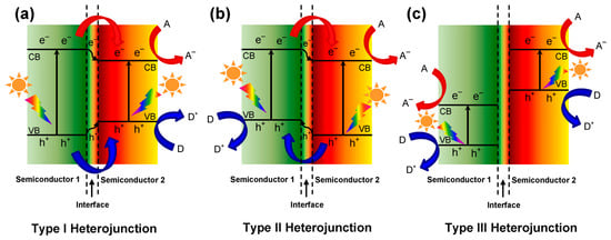
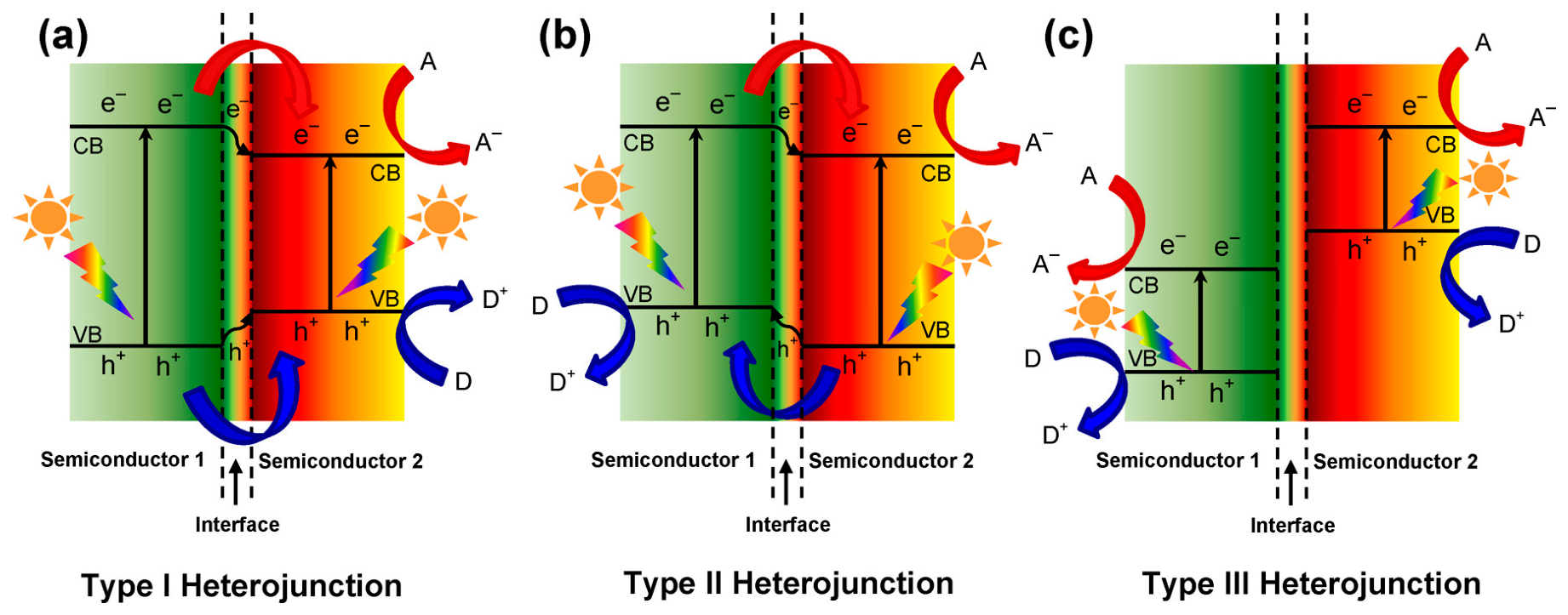
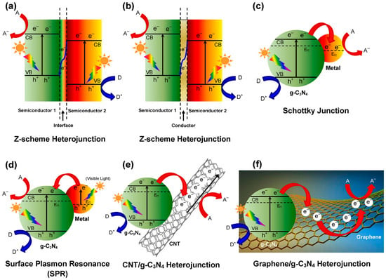
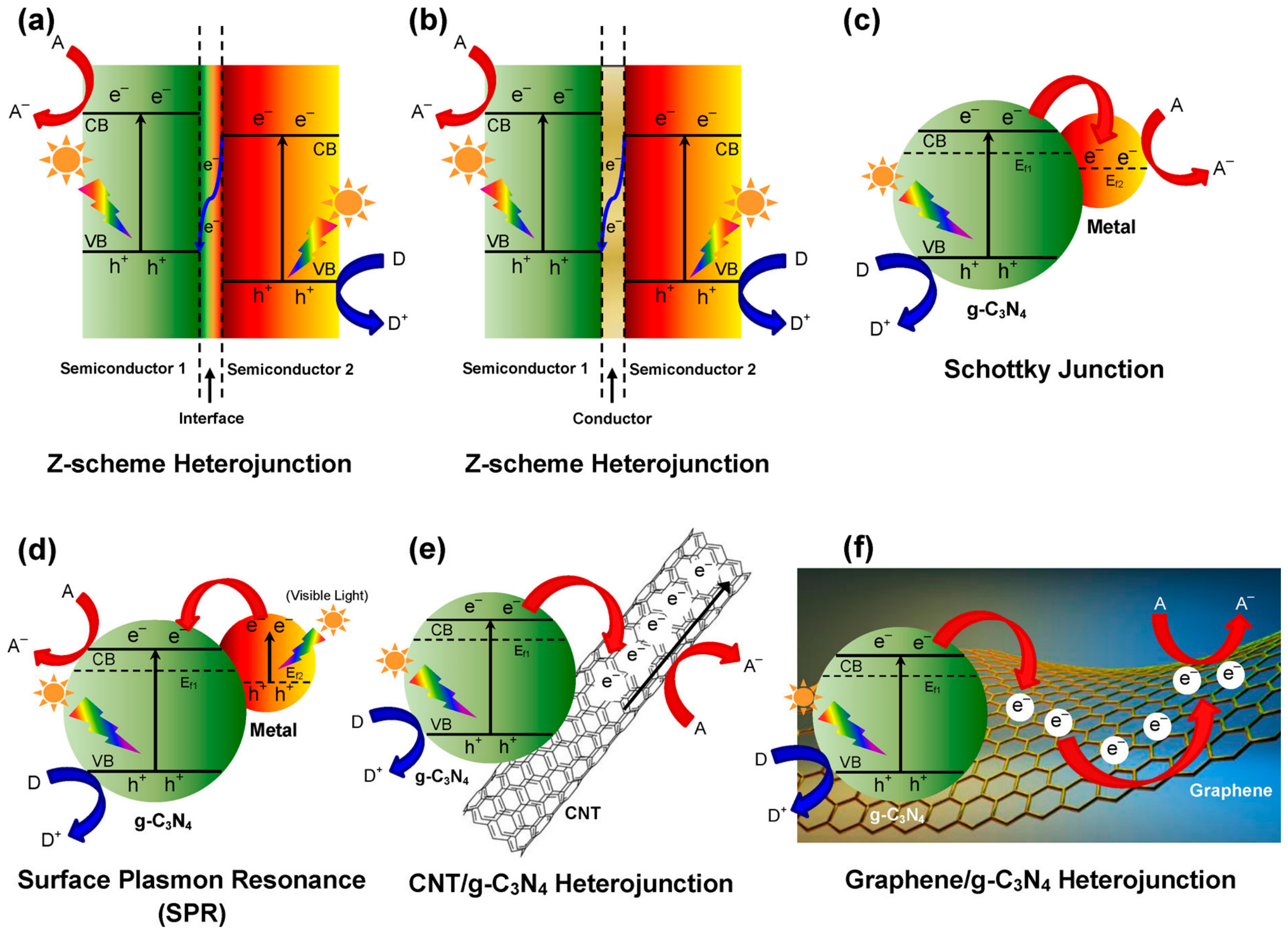
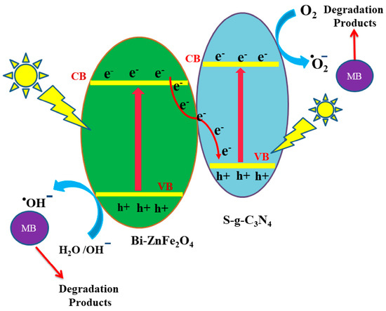
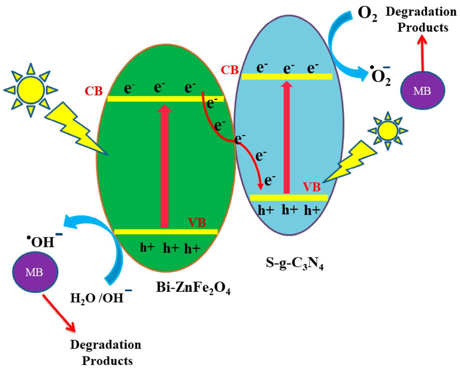
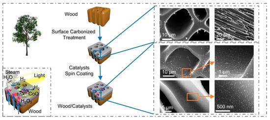
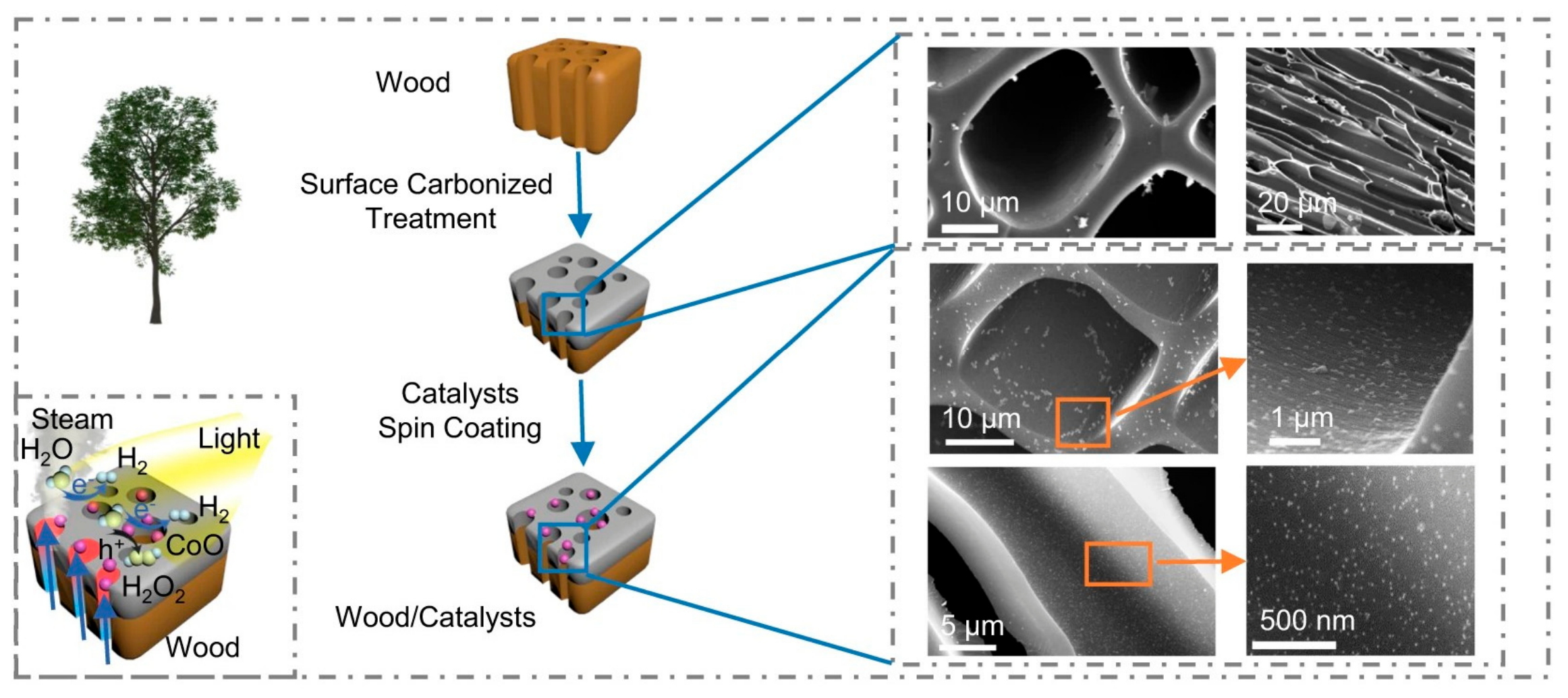
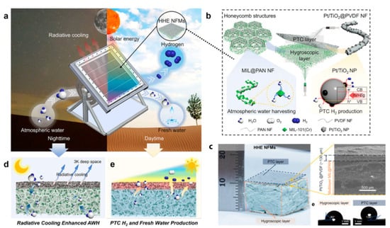
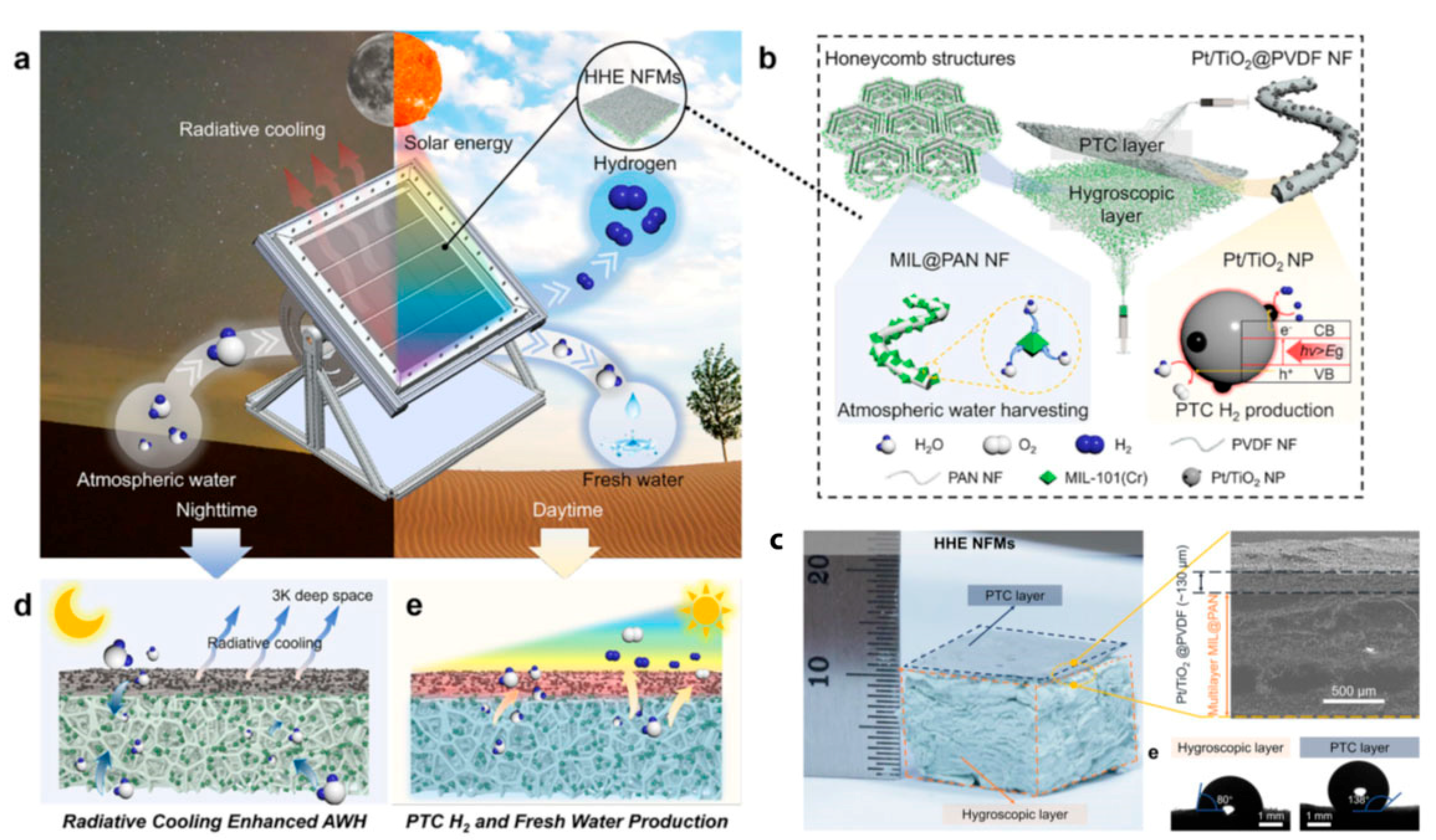
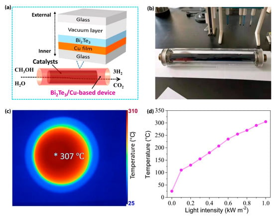
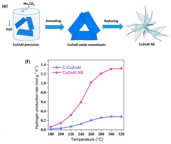
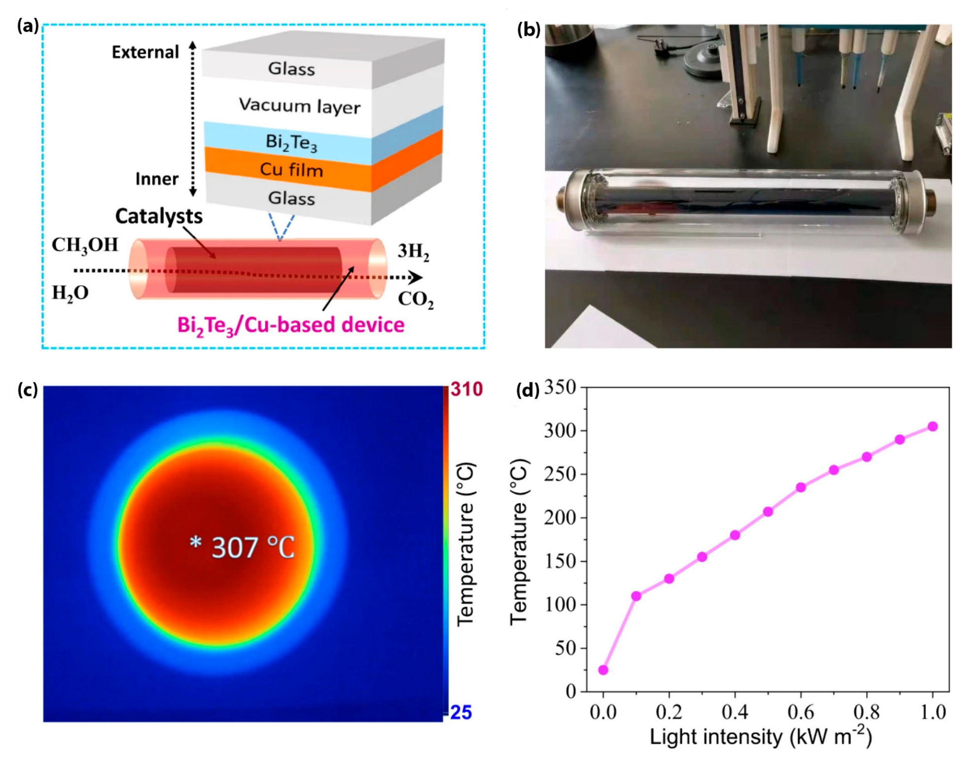
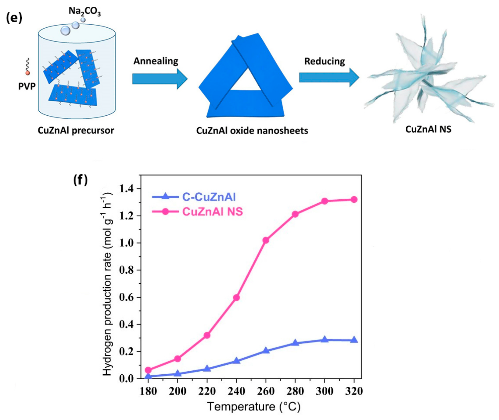
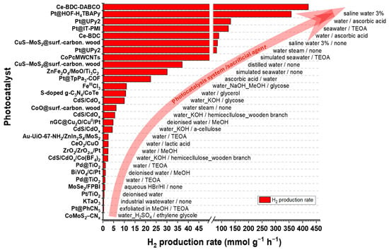
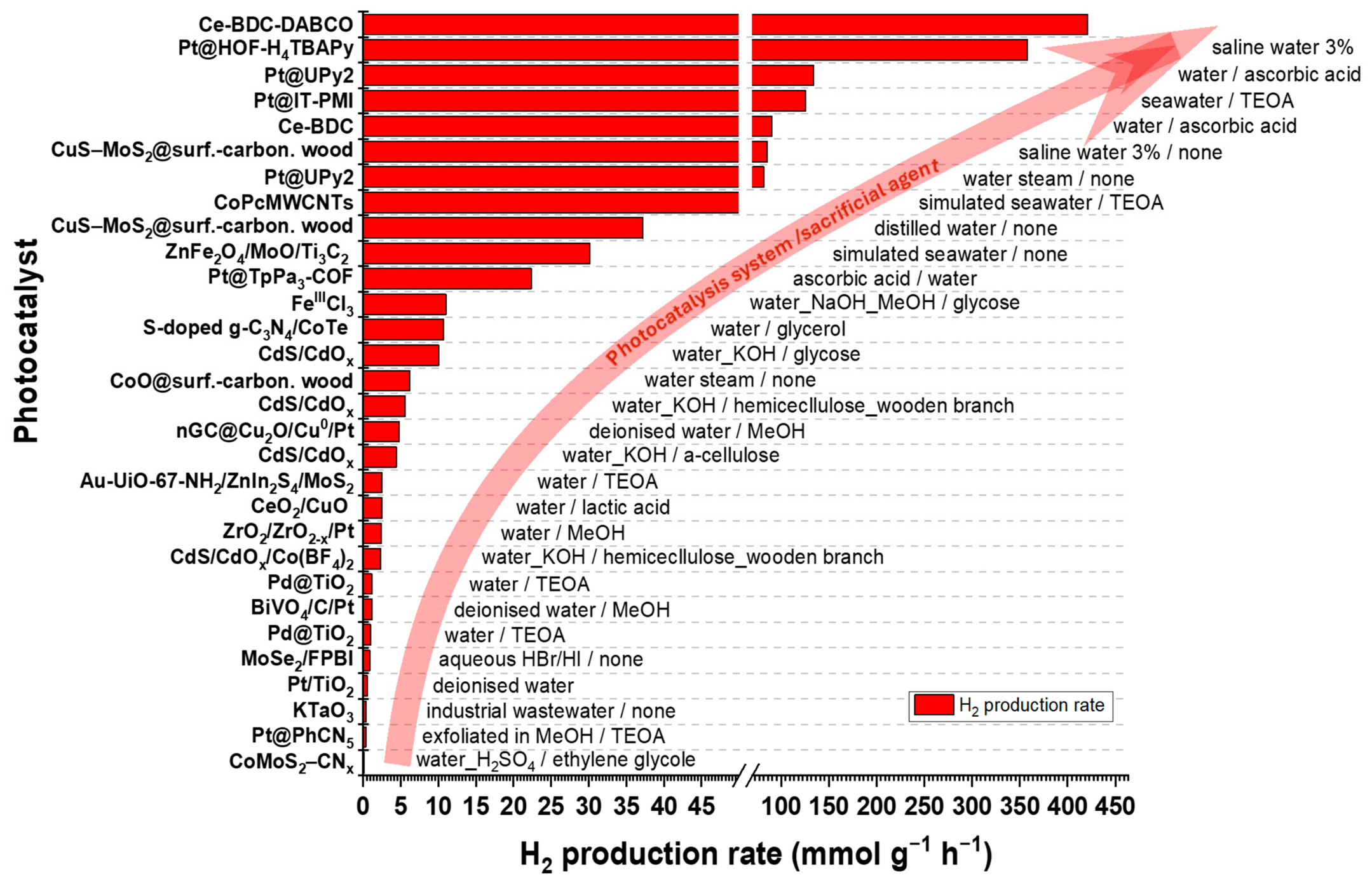
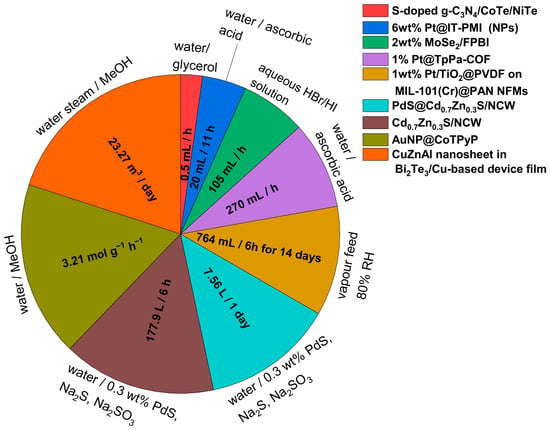
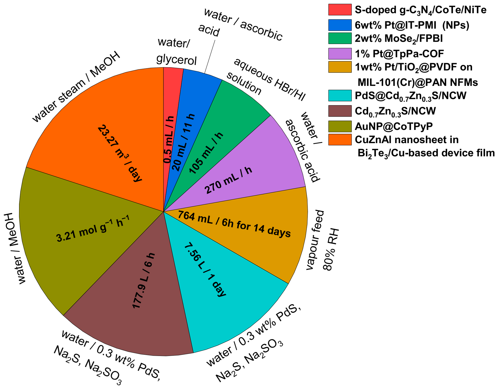
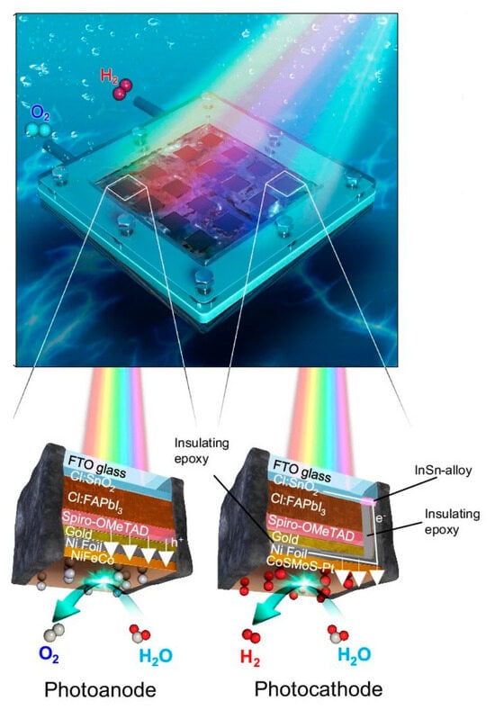
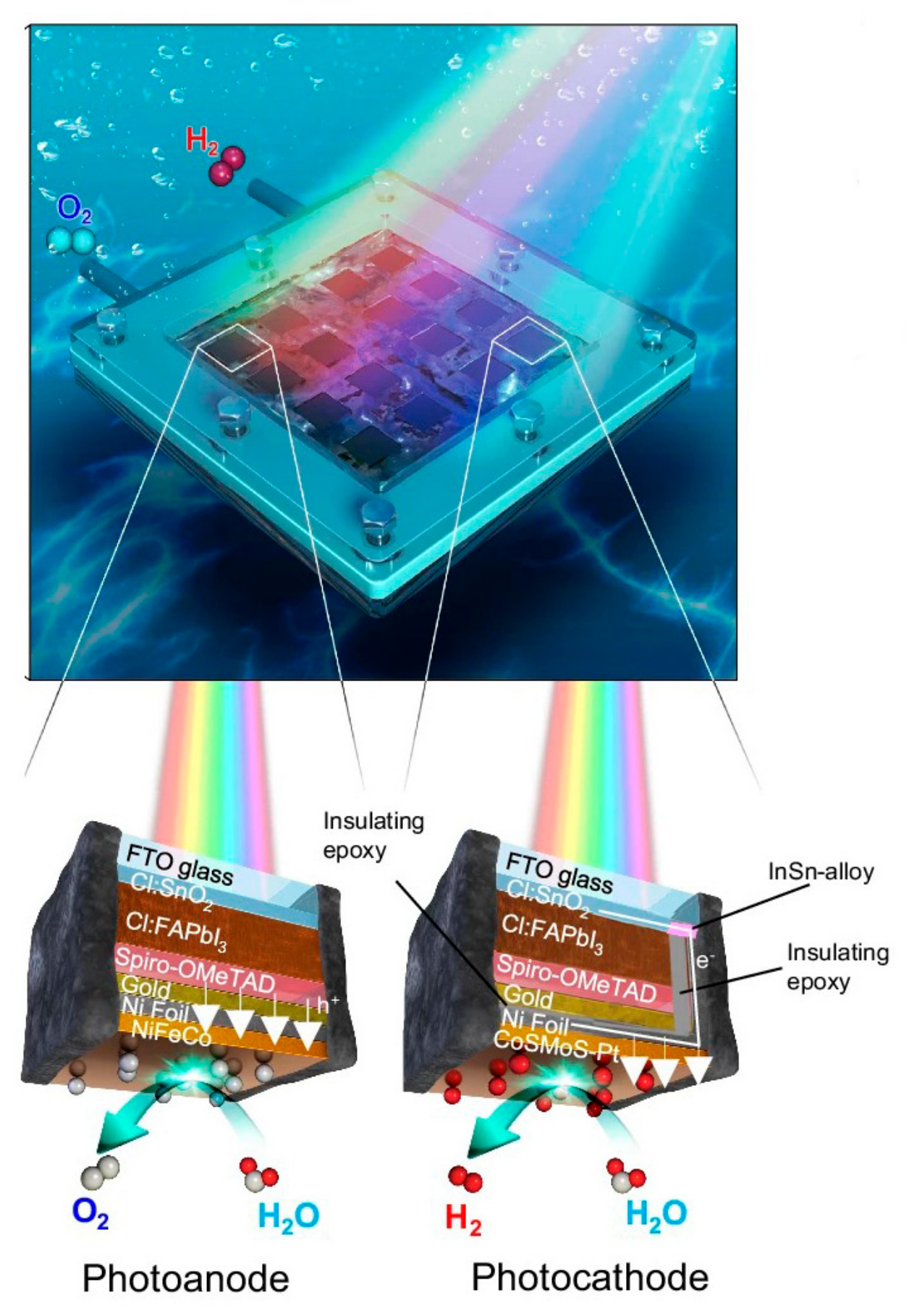
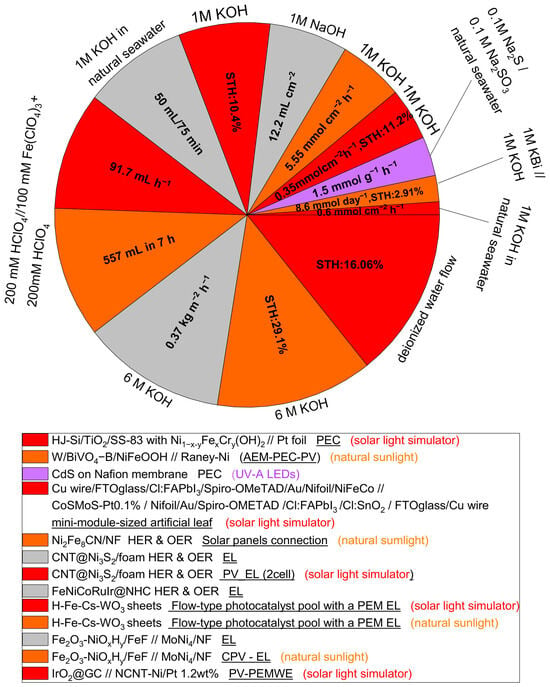
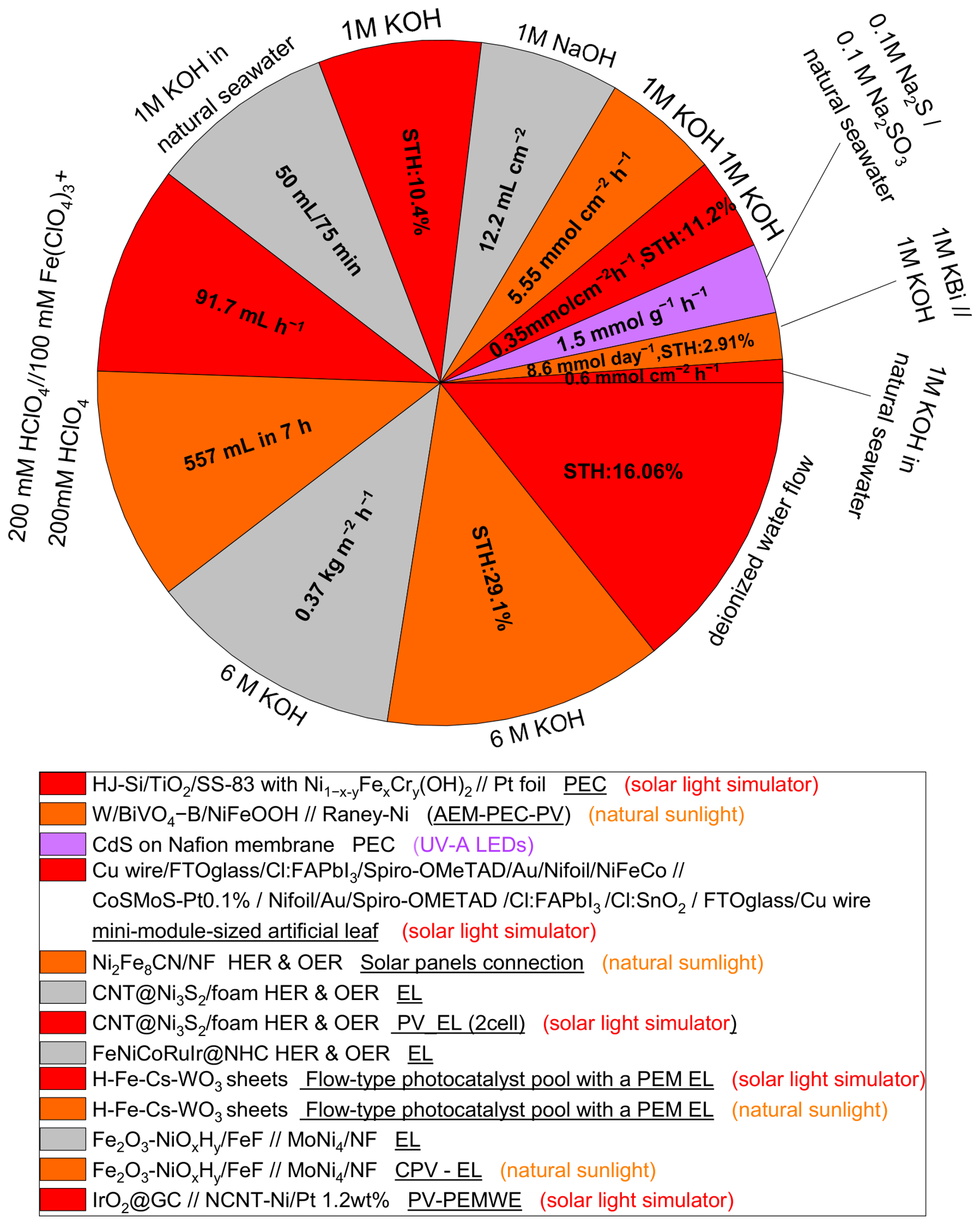
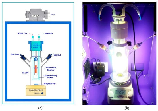
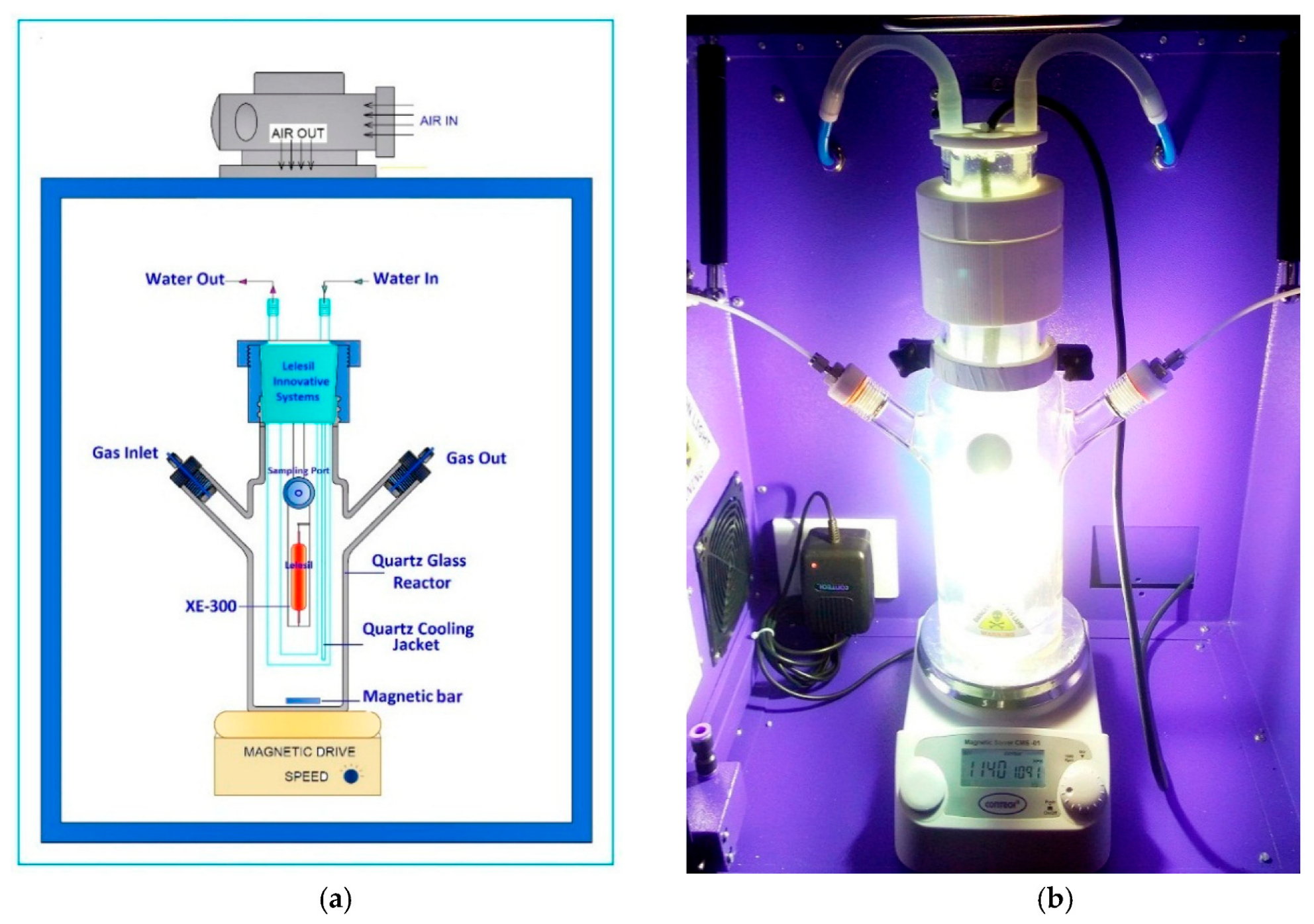
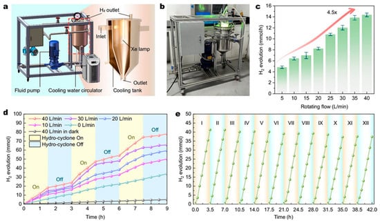
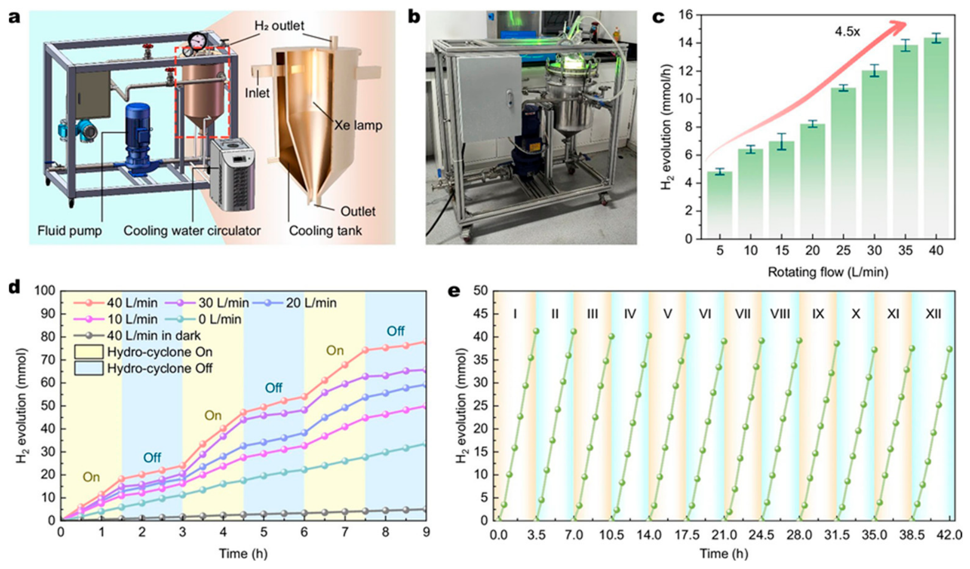
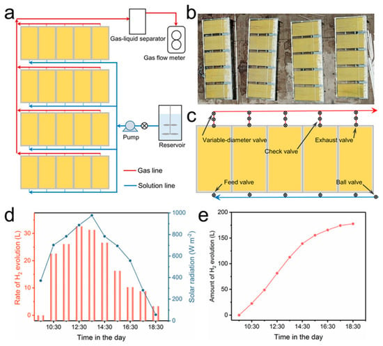
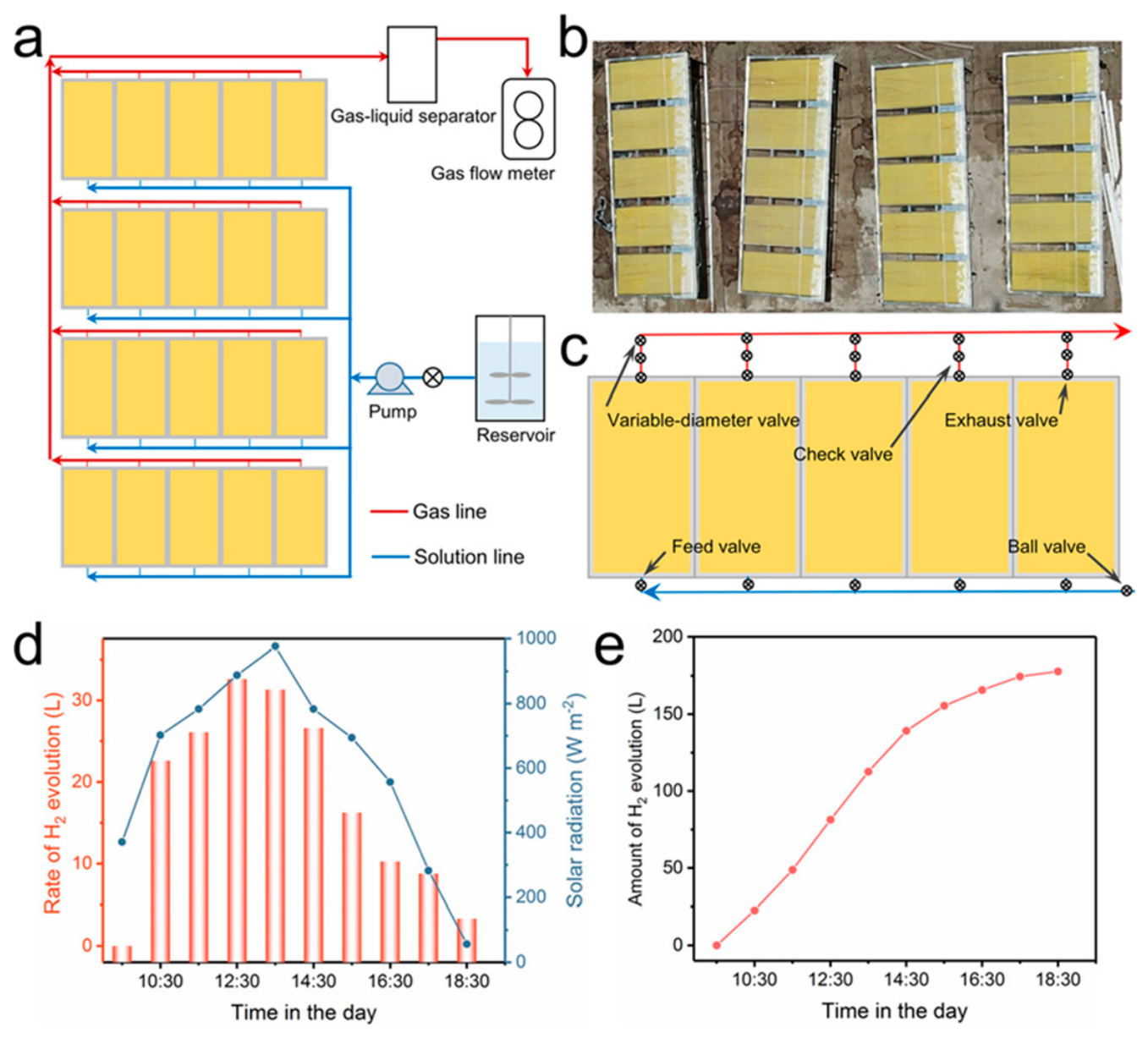
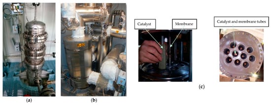
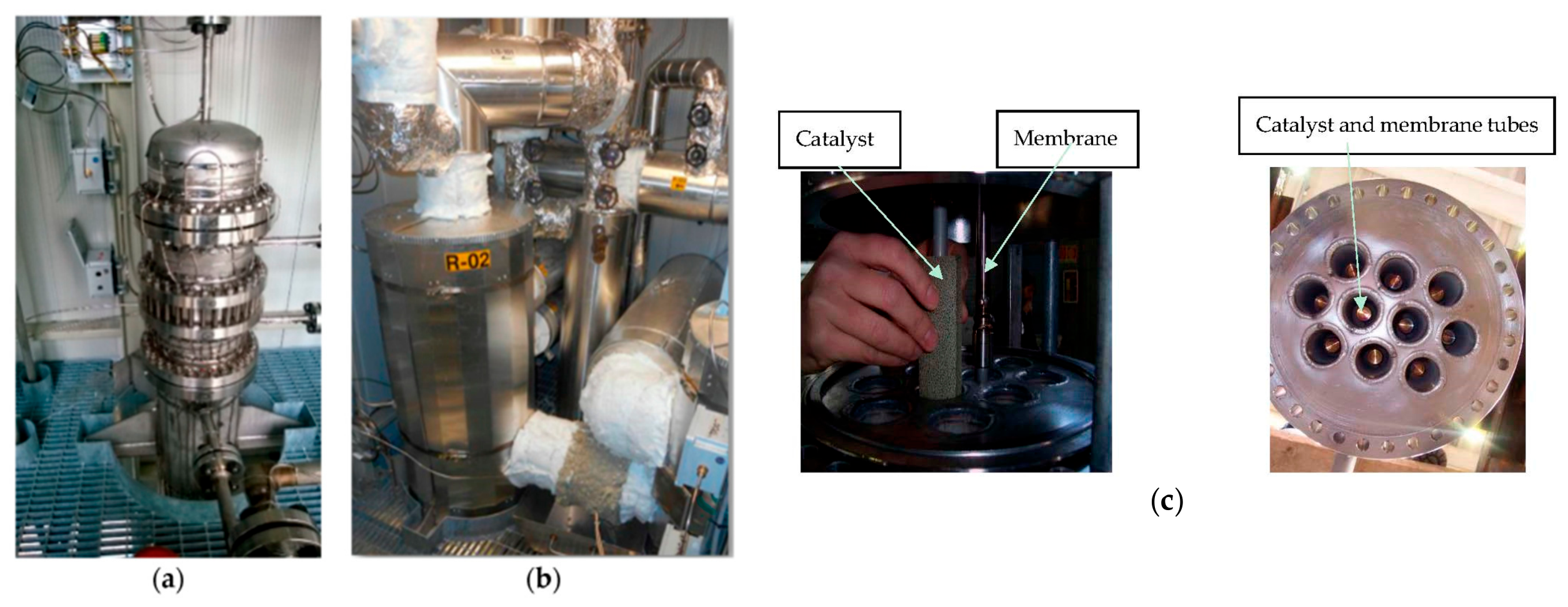
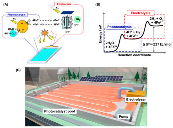
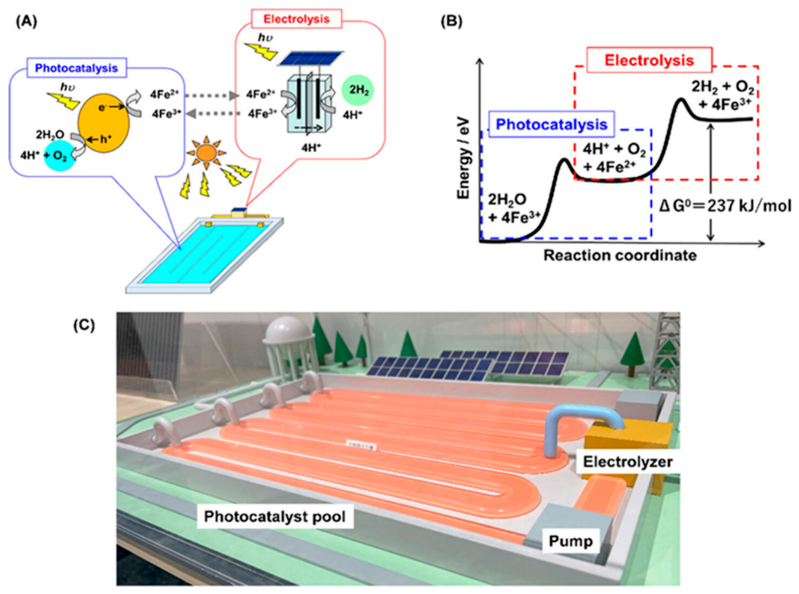
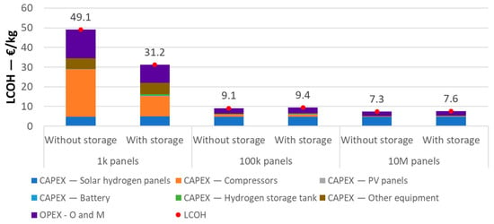
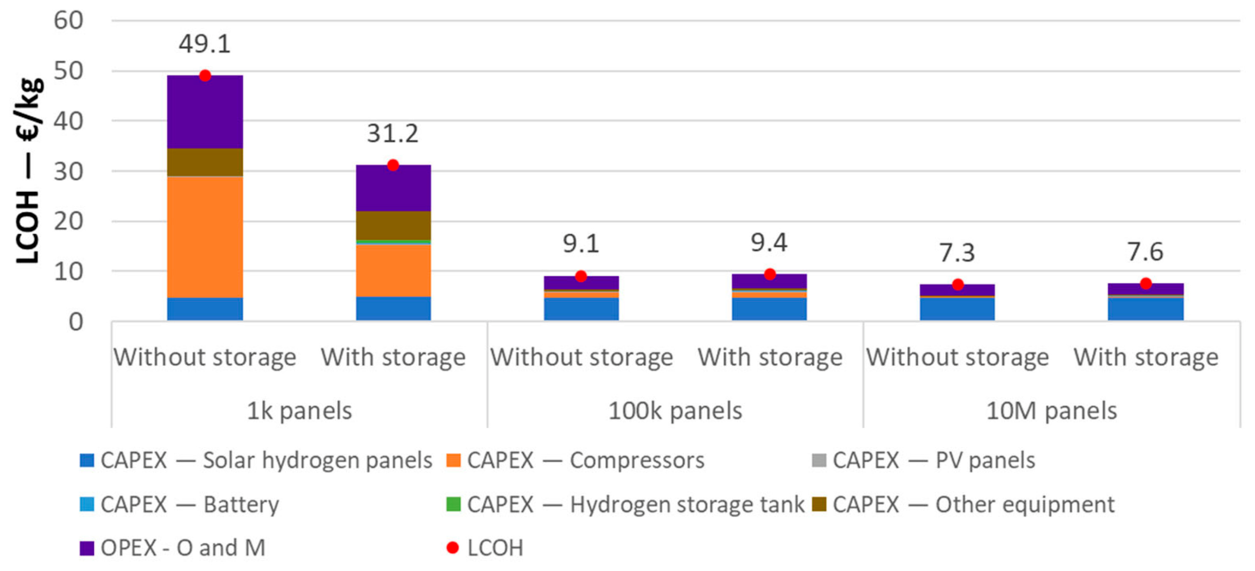
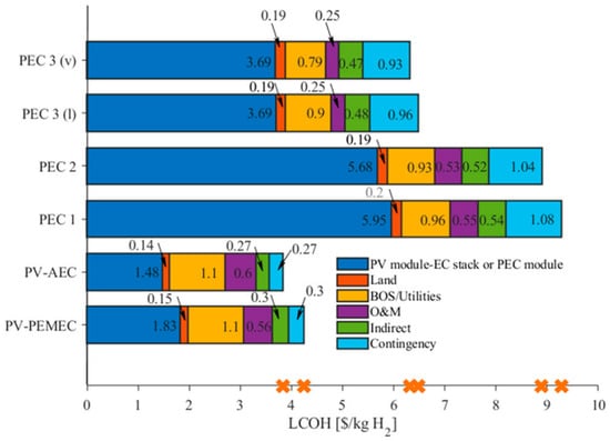
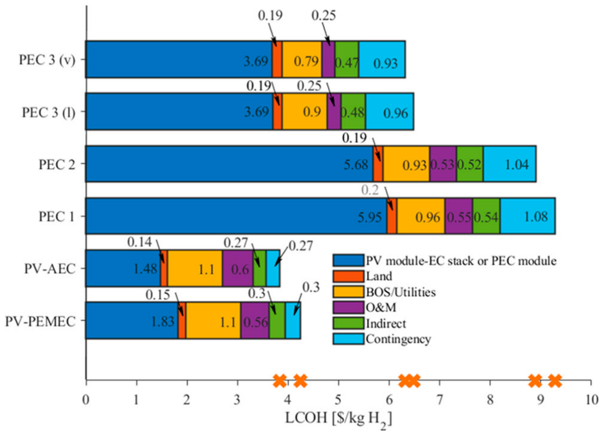
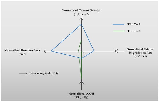
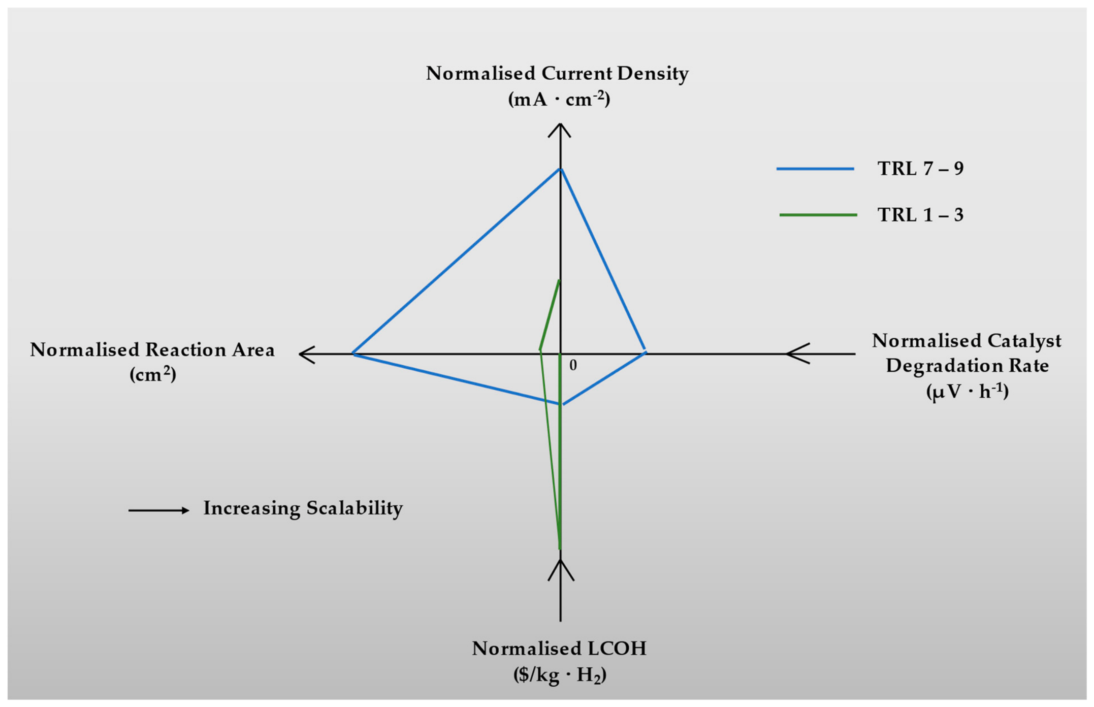

Disclaimer/Publisher’s Note: The statements, opinions and data contained in all publications are solely those of the individual author(s) and contributor(s) and not of MDPI and/or the editor(s). MDPI and/or the editor(s) disclaim responsibility for any injury to people or property resulting from any ideas, methods, instructions or products referred to in the content. |
© 2026 by the authors. Licensee MDPI, Basel, Switzerland. This article is an open access article distributed under the terms and conditions of the Creative Commons Attribution (CC BY) license.