


Abstract
This paper proposes an efficient analytical modeling method for the air-gap flux density in hydro-generators under eccentricity faults. The method specifically addresses the multi-factor coupling characteristics induced by the combined effects of stator slotting, salient-pole rotor structure, and eccentricity. Based on geometric analytical derivation, individual models for air-gap length considering stator slotting, rotor salient-pole structure, and eccentricity are established, and an analytical expression for the air-gap length under coupled conditions is derived. By incorporating the spatial distribution characteristics of the magnetomotive force, a mathematical model for no-load air-gap flux density is constructed, enabling the rapid calculation of air-gap magnetic field distribution. Finite element verification conducted on an 84-slot, 10-pole hydro-generator demonstrates that the proposed method accurately reflects the periodic fluctuations and amplitude variations in the magnetic flux density under both normal and eccentric conditions. Compared with the finite element method (FEM), the analytical approach significantly enhances computational efficiency while maintaining high accuracy, providing effective theoretical support for the structural optimization and eccentricity fault diagnosis of hydro-generators.
1. Introduction
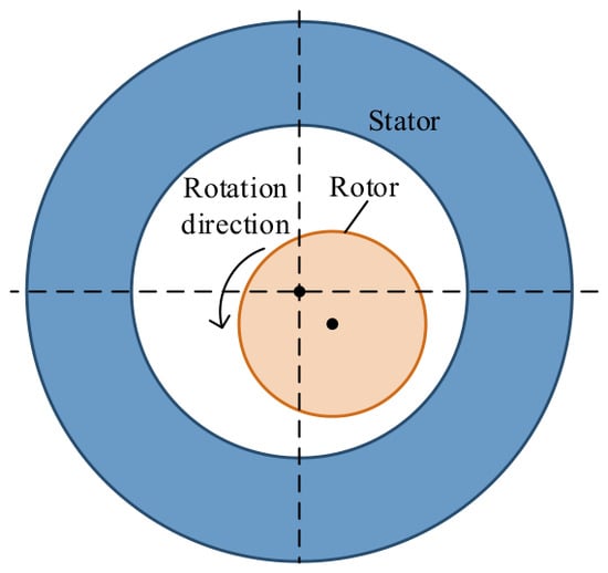
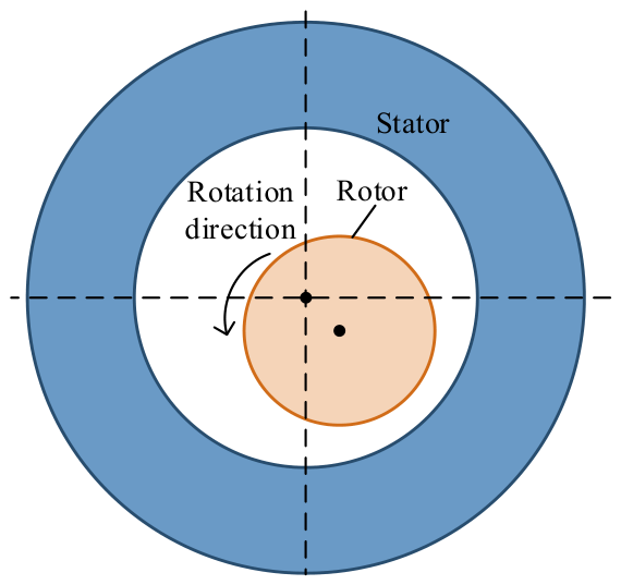
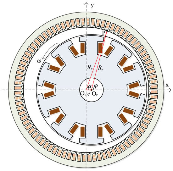
Hydropower generators are characterized by large structures and high assembly precision requirements [1,2,3]. Under long-term operation or manufacturing errors, the rotor is prone to eccentricity relative to the stator. A schematic diagram illustrating the rotor eccentricity is shown in Figure 1. The salient-pole structure of the rotor typically shows a displacement of its geometric center with respect to the motor’s central axis, resulting in a non-uniform air-gap length along the circumferential direction [4,5,6,7]. The asymmetric distribution of the air gap is jointly influenced by the rotor’s salient-pole structure and the stator slotting effect, leading to complex spatial distortion of the air-gap flux density. This distortion directly affects the back electromotive force and electromagnetic torque characteristics, thereby causing issues such as vibration, noise, and reduced operational stability. To address the air-gap magnetic field distortion caused by eccentricity, various modeling and analysis methods have been proposed by researchers worldwide [8,9,10].
Figure 1.
Schematic diagram of rotor eccentricity.
At present, the calculation methods for air-gap flux density can be broadly classified into two categories: the finite element method [11,12,13] and analytical methods [14,15]. Numerical methods represented by FEM can account for complex structural features such as material nonlinearity and end effects, offering high computational accuracy. However, they suffer from long computation times, high resource consumption, and strong dependence on mesh quality, making them less suitable for rapid prediction of motor magnetic fields [16,17,18]. In contrast, analytical methods feature high computational efficiency and can establish explicit mathematical relationships between structural parameters and magnetic field distribution, and have thus become an important research direction in electrical machine modeling.
However, most existing studies mainly focus on investigating the influence of eccentricity faults on electromagnetic characteristics through finite element analysis, which requires considerable computational resources and limits its application in real-time condition monitoring. Recently, electromagnetic sensing and intelligent monitoring technologies have provided new approaches for equipment condition assessment. Cai et al. reviewed electromagnetic-based energy harvesting technologies [19], while Zuo et al. proposed an intelligent key-point detection method for industrial equipment monitoring [20]. These studies demonstrate the potential of electromagnetic characteristics and intelligent algorithms in condition monitoring. Therefore, developing an accurate and computationally efficient analytical model is of great significance for rapidly evaluating electromagnetic performance under eccentricity conditions.
Reference [21] combines the equivalent magnetic circuit method with magnetic potential analysis to establish an analytical model of the air-gap magnetic field in permanent magnet machines considering slotting effects. By incorporating stator slot boundary conditions, this approach enables accurate calculation of air-gap flux density distribution, back EMF, and torque waveforms. However, this study focuses on permanent magnet machines and does not involve electrically excited structures or rotor salient-pole structures, limiting the applicability of the model. Reference [22] proposed an analytical air-gap magnetic field model considering the slotting effect based on the superposition principle, which can accurately predict the cogging torque characteristics of permanent magnet machines. Nevertheless, this model is still based on the assumption of a cylindrical rotor and does not account for the non-uniform air-gap distribution caused by the rotor salient-pole structure.
This paper addresses the problems of structural complexity, non-uniform air-gap distribution, and significant slotting coupling effects in hydro-generators by proposing a no-load air-gap flux density modeling method. Based on the geometric characteristics of the hydro-generator, models are established to describe the influences of stator slotting and rotor salient-pole structure on the air-gap length, and an analytical expression of the air-gap length under multi-factor coupling conditions is derived. By incorporating the spatial distribution characteristics of the magnetomotive force generated by the excitation winding, accurate calculation of the air-gap magnetic field distribution is achieved.
In the proposed method, the air-gap length is expressed as the superposition of three components induced by operating condition variations, slotting effects, and the rotor salient-pole structure. Each component is modeled individually and solved within a unified analytical framework, leading to an analytical expression for the air-gap flux density. The proposed model significantly improves computational efficiency while maintaining high accuracy. Finally, the analytical results are compared with finite element simulations, showing good agreement, which verifies the correctness and engineering applicability of the model.
2. Analytical Calculation of Non-Uniform Air-Gap Length Under Eccentricity Fault Conditions
2.1. Analysis of Influencing Factors on Air-Gap Length in Hydropower Generators
The air-gap length is a key parameter that determines the electromagnetic performance of rotating electrical machines. Its variation directly affects the air-gap permeance, flux density distribution, and consequently the electromagnetic torque. Under uniform air-gap conditions, the symmetry of the magnetic circuit results in a regular distribution of air-gap flux density. However, in the presence of eccentricity faults, the air-gap length becomes non-uniform along the circumferential direction, and the actual air-gap function must be obtained through accurate calculation.
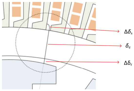
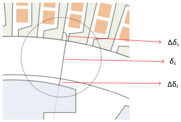
Under eccentric operating conditions in hydropower generators, the air-gap length is mainly influenced by three factors: first, rotor eccentricity; second, the stator slotting effect, which causes non-uniformity of the air-gap distribution on the stator side; and third, the rotor salient-pole structure, which leads to alternating variations in air-gap width on the rotor side. The air-gap length can thus be expressed as
where δe(φ) denotes the air-gap length, which varies with the rotor position angle φ, Δδs(φ) represents the variation in air-gap length caused by the stator slotting structure, and Δδr(φ) represents the variation in air-gap length due to the rotor salient-pole structure.
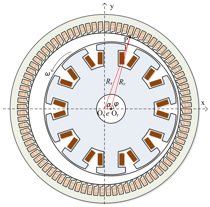
Figure 2 illustrates a schematic diagram of the air-gap length in a hydropower generator. In the figure, Rs is the inner radius of the stator, and Rr is the outer radius of the rotor.
Figure 2.
Schematic diagram of the air-gap length of the hydro-generator.
Under normal operating conditions, the air-gap between the stator and rotor is uniformly distributed, and the air-gap length δe of the hydro-generator remains constant. However, in the event of an eccentricity fault, the rotor’s geometric center deviates from the stator’s center, causing the air-gap length to vary with the circumferential angle. Consequently, the air gap distribution becomes non-uniform, and δe is no longer constant.
2.2. Analytical Calculation of Air-Gap Length Under Eccentricity Fault Conditions
As shown in Figure 3, a stator coordinate system is established, with the center Os taken as the origin. The inner radius of the stator is Rs, and the outer radius of the rotor is Rr. The rotor center is denoted as Or, whose coordinates in the stator coordinate system are (e, 0). An arbitrary point on the inner surface of the stator is denoted as P, and its coordinates can be expressed as (Rscosα, Rssinα).
Figure 3.
Diagram of stator coordinate system.
Based on the geometric relationship, the air-gap length δ(α) in the stator coordinate system can be obtained as [21]
By applying Fourier series expansion, δ(α) can be further expressed as a series consisting of a constant term and cosine components.
where
and
In eccentricity fault analysis, the rotor is usually taken as the reference coordinate system. Therefore, Equation (2) needs to be reformulated in the rotor coordinate system. To accomplish this coordinate transformation, the relationship between the angular position α in the stator coordinate system and the angular position α in the rotor coordinate system must be established.
In the rotor coordinate system, with the rotor center Or as the origin, the coordinates of an arbitrary point P on the inner surface of the stator are (Rscosα − e, Rssinα). Let |r| denote the distance between Or and P. In this coordinate system, the trigonometric relationship of the rotor angular position can be expressed as
From Equation (4), it can be seen that the rotor angle is related to the stator angle through trigonometric functions. By performing algebraic manipulation and introducing an approximation under the condition that the eccentricity is much smaller than the rotor inner radius, we obtain:
From this, a simplified expression describing the angular relationship can be obtained:
By combining Equation (2) with Equation (6), an analytical expression for the variation in air-gap length with rotor angle under eccentric conditions can be derived:
2.3. Analytical Calculation of Air-Gap Length with Rotor Salient-Pole Structure Taken into Account
Hydropower generators typically employ a rotor salient-pole structure to meet the requirements of low-speed, high-torque operation. The rotor poles are often designed in an arc shape, but the center of this arc does not coincide with the geometric center of the machine, forming an eccentric pole structure—hereafter referred to collectively as the eccentric pole structure.
Compared with a machine with concentric poles, the air-gap distribution in a generator with an eccentric pole structure is no longer uniform, gradually increasing in direction away from the pole center. This variation in air-gap width directly affects the magnetic permeance between the stator and rotor, thereby altering the air-gap flux density. Therefore, to accurately describe the distribution characteristics of the air-gap flux density, it is necessary to reasonably model the air-gap length of hydropower generators.
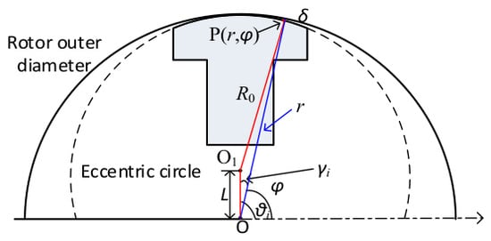
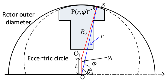
As illustrated in Figure 4, the rotor region of the hydropower generator is simplified into a geometric model characterized by an offset center. Here, O and O1 denote the geometric center of the rotor and the center of the eccentric pole structure, respectively. An arbitrary point on the pole arc is denoted as P, whose polar coordinates are (r,φ). The parameter L represents the distance between the two centers, θi denotes the angular position of the centerline of the i-th magnetic pole, and R0 represents the radius of the pole arc. For the convenience of subsequent air-gap length calculation, the angular difference is defined as γi = |θi − φ|.
Figure 4.
Simplified diagram of the rotor region of the hydrogenerator.
In triangle OO1P, the following relationship can be derived according to geometric relationships:
By rearranging this equation, the expression for the radius r can be obtained as
Therefore, the air-gap length variation Δδr induced by the salient-pole structure can be expressed as
2.4. Analytical Calculation of Air-Gap Length with Slotting Effect Taken into Account
To facilitate the analysis of the influence of the stator slotting effect on the air-gap characteristics of the machine, the following simplifying assumptions are adopted:
- (1)
- The influence of end effects is neglected.
- (2)
- The inner surface of the stator is assumed to be smooth with ideal slot openings, and detailed structures such as tooth-tip chamfers are not considered.
- (3)
- The stator slot geometry is idealized as rectangular slots, and the slot depth is assumed to be infinitely large.
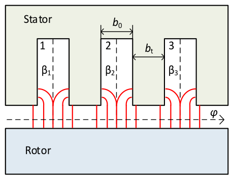
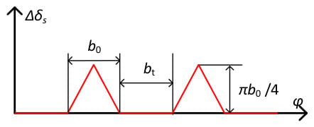
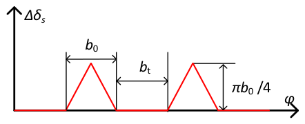
Under the above assumptions, a geometric model of the air-gap length can be established, as illustrated in Figure 5. In the model, βi denotes the mechanical angular position of the centerline of the i-th slot opening, b0 represents the slot opening width, and bt denotes the tooth width.
Figure 5.
Air-gap magnetic circuit model considering slotting effects.
Under this model, the stator slotting structure causes different equivalent magnetic path lengths at the tooth tips and slot openings, resulting in a periodic variation in the air-gap length along the circumferential direction. The air-gap length variation induced by the stator slotting effect can be described by an analytical expression [7] and a schematic diagram, as given below, where τ denotes the slot pitch and x = |φ − βi|.
Through Fourier series expansion, Δδs(α) can be represented as a sum of a constant term and cosine harmonics.
where
and
3. Analytical Modeling of Electromagnetic Performance in a Hydropower Generator
3.1. Analytical Modeling of Air-Gap Flux Density
The magnetomotive force of a hydro-generator is determined by the excitation current and can be flexibly adjusted according to the number of turns of the field winding and the magnitude of the current. The expression for the magnetomotive force is given by
where N is the number of turns of the field winding, and if denotes the excitation current.
During actual machine operation, in addition to the main magnetic flux forming the effective magnetic field through the air gap, a portion of the flux flows through non-main magnetic paths such as the machine frame, stator slots, and end regions, giving rise to leakage flux. As a result, the air-gap magnetic flux density deviates from the ideal distribution. To accurately characterize this effect, the magnetic flux density integration method is adopted in this paper to calculate the leakage coefficient. This method evaluates the ratio between the magnetic flux density integrated along the main magnetic path and that integrated along the total magnetic path, thereby obtaining the leakage coefficient kl. The corresponding expression is given by
where Bm and Bδ denote the magnetic flux densities along the main magnetic path and the total magnetic path, respectively, and lm and lδ represent the corresponding integration path lengths.
After obtaining the leakage coefficient, it can be incorporated into the air-gap magnetic flux density calculation to correct the results derived from the analytical model. In practical machines, part of the magnetic flux closes through non-air-gap paths, resulting in a reduction in the effective magnetic flux passing through the air gap compared with the theoretical prediction. Therefore, the leakage coefficient can be introduced as a correction factor into the air-gap magnetic flux density expression to adjust the analytically obtained magnetic flux density distribution. The expression for the corrected air-gap magnetic flux density is given by
Based on the magnetic field data obtained from finite element analysis, the magnetic flux density can be integrated along the main magnetic path and the total magnetic path, respectively, to determine the leakage coefficient at different positions of the machine. After introducing the leakage coefficient, the air-gap magnetic flux density is corrected, and the resulting distribution more closely reflects the actual magnetic field characteristics of the machine.
3.2. Analytical Model of Back EMF
After obtaining the air-gap magnetic flux density distribution, the back EMF and electromagnetic torque of the machine can be further calculated. First, the flux linkage of each phase is obtained by integrating the air-gap magnetic flux density, which can be expressed as
where x = A, B, C; Nx is the number of turns of the x-phase winding, r denotes the air-gap radius, and l denotes the axial length of the hydropower generator.
The no-load back EMF of the hydro-generator can be calculated from the flux linkage as
3.3. Analytical Model of Electromagnetic Torque
After obtaining the no-load back EMF, electromagnetic energy conversion occurs when armature currents are applied to the machine. Based on the relationship between the back EMF and the armature current, the electromagnetic torque expression can be further derived.
Assuming that the hydro-generator is supplied with balanced three-phase sinusoidal currents, the currents can be expressed as
where
In the above, n denotes the rotational speed of the hydro-generator, and p is the number of pole pairs.
By combining the obtained back EMF and phase currents, the electromagnetic torque can be calculated, which is expressed as
4. Finite Element Simulation Validation
To verify the effectiveness of the proposed method for calculating the no-load air-gap magnetic flux density of a hydro-generator, an 84-slot, 10-pole generator is selected as a case study for simulation analysis. First, a finite element model of the hydro-generator is established to simulate its normal operating conditions, and the main machine parameters are listed in Table 1.
Table 1.
Table of motor parameters and configuration.
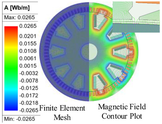
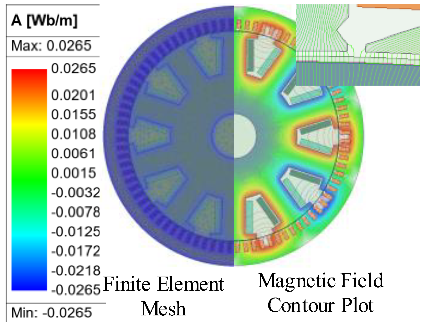
After establishing the complete machine model, finite element meshing is performed to ensure the accuracy of the simulation and the reliability of the results. By appropriately setting the mesh density in the stator, rotor, and air-gap regions, the complex electromagnetic field distribution inside the machine can be accurately captured. Based on this, magnetic field simulations are carried out, and the magnetic field distribution of the machine under a no-load condition is obtained, as shown in Figure 6. Specifically, the left part of Figure 6 illustrates the meshing results of the machine model, while the right part presents the corresponding magnetic field distribution contour.
Figure 6.
Finite element mesh and magnetic field contours of the motor.
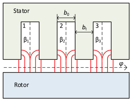
As shown in the upper-right part of Figure 7, the magnetic field lines in the stator region exhibit an approximately quarter-circular arc distribution, which is consistent with that in Figure 2. This indicates that the flux distribution in the air gap agrees well with the theoretical prediction, thereby validating the correctness of the proposed model.
Figure 7.
Schematic of air-gap length under the influence of the slotting effect.
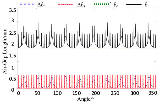
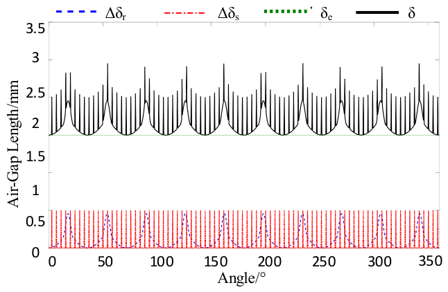
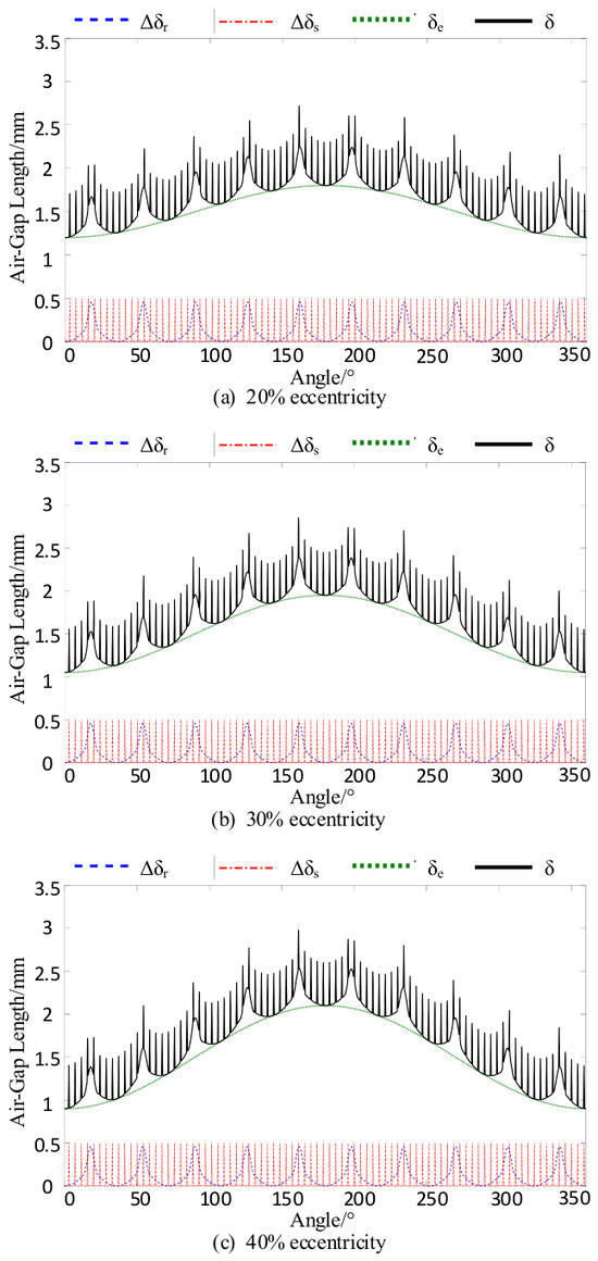
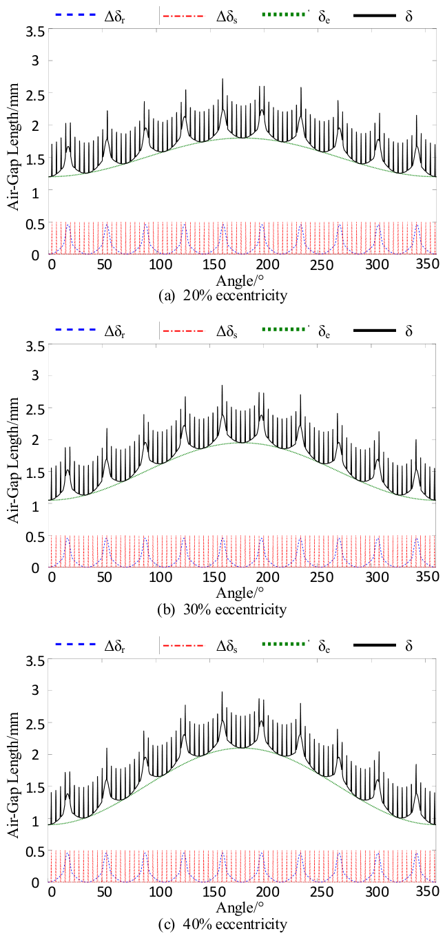
To further validate the calculation accuracy of the analytical model, the air-gap length distributions under both normal and eccentric conditions were comparatively analyzed using FEM and the analytical method. Figure 8 and Figure 9 present the calculation results for these two conditions, respectively. The comparison intuitively demonstrates the accuracy of the proposed analytical model under different operating states.
Figure 8.
Air-gap length variation under different factors.
Figure 9.
Analytical distribution of air-gap length under different eccentricity levels.
4.1. Simulation Validation of Air-Gap Flux Density
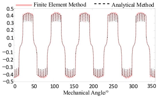
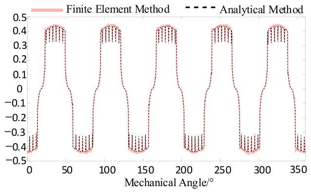
To better reflect the actual operating conditions, analyses were conducted both with and without taking into account the leakage coefficient. Figure 10 compares the results obtained by the two methods without introducing the leakage coefficient, while Figure 11 presents a comparison of the air-gap flux density distributions derived from the finite element method and the analytical method after the leakage coefficient is taken into account.
Figure 10.
Air-gap flux density obtained by two methods without leakage coefficient.
Figure 11.
Air-gap flux density obtained by two methods with leakage coefficient.
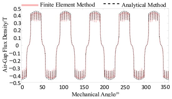
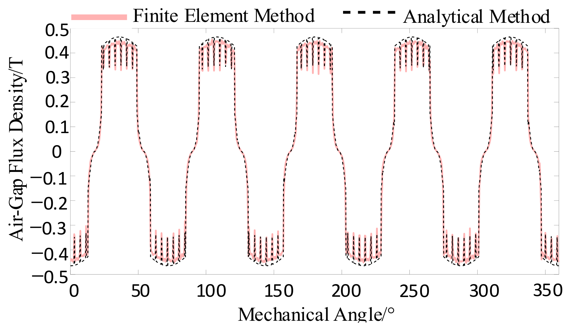
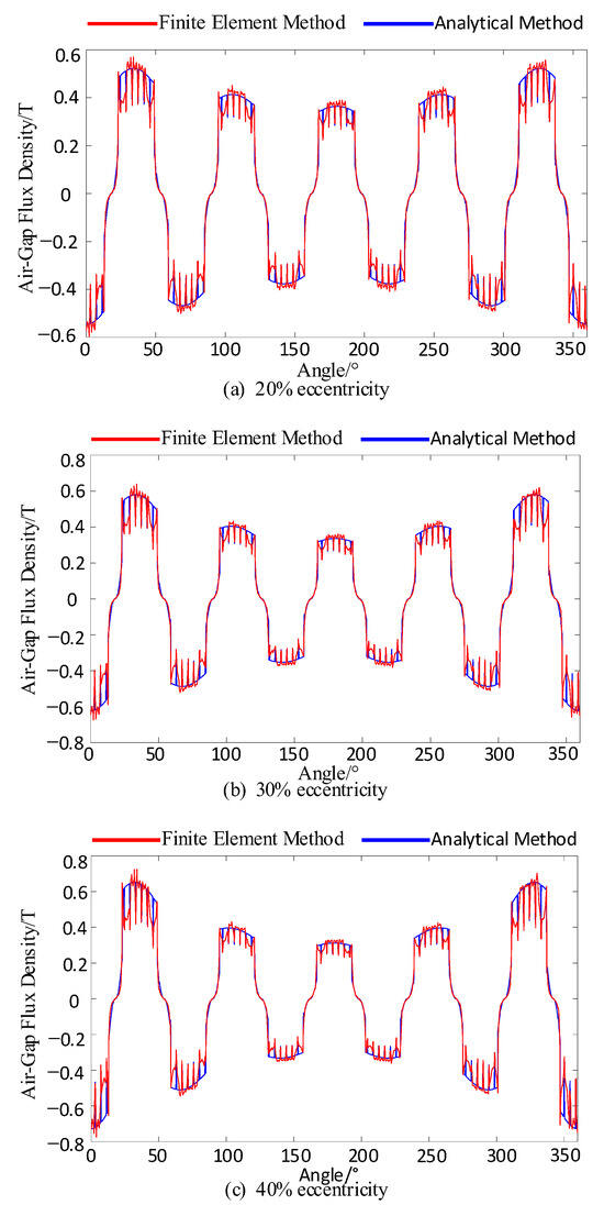
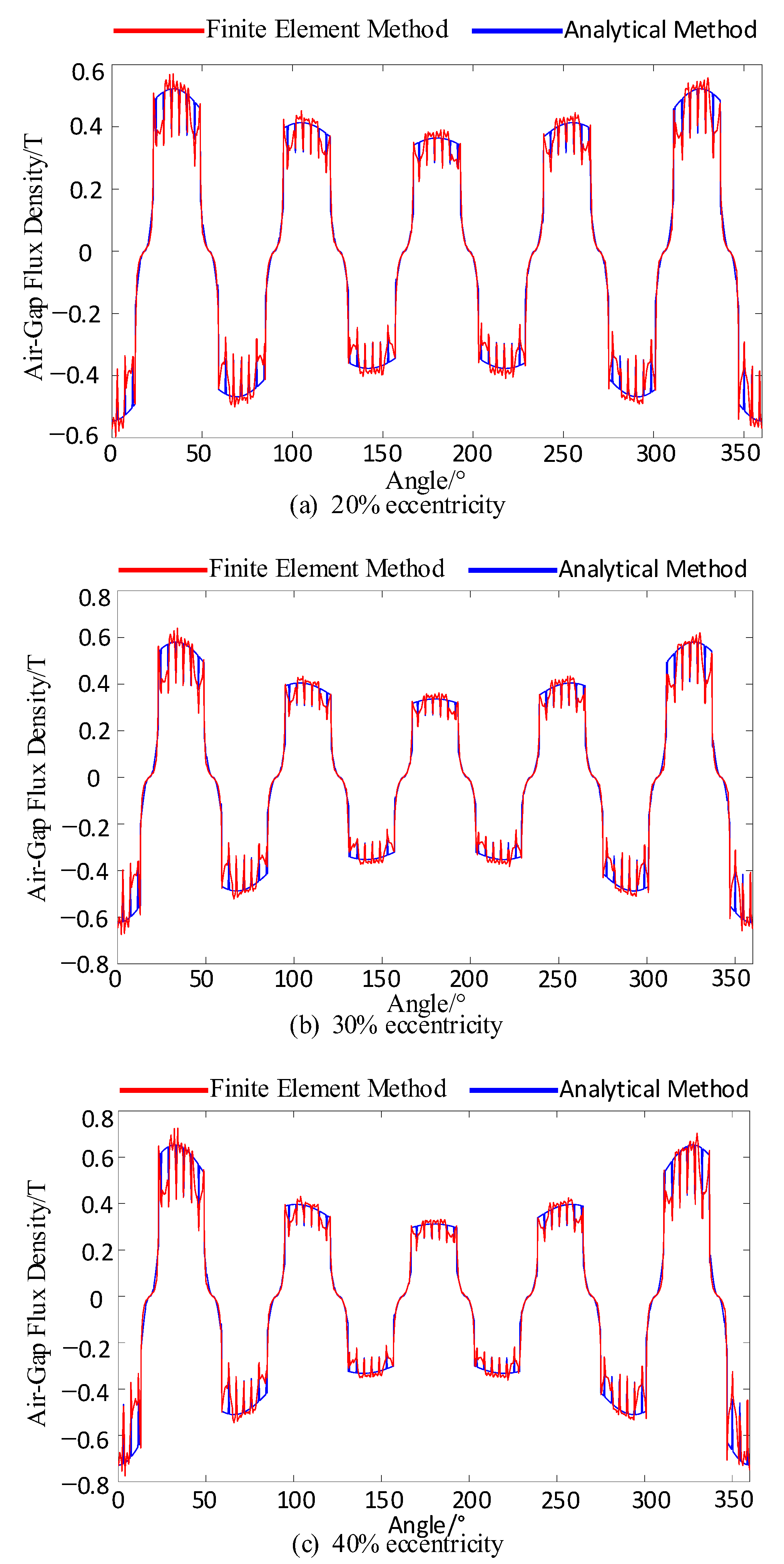
As illustrated in Figure 11, after incorporating the leakage flux coefficient correction, the air-gap magnetic flux density obtained by the analytical method shows good agreement with the finite element results, validating the effectiveness of the proposed model under normal conditions. To further investigate the impact of eccentricity faults on the air-gap magnetic field distribution, rotor eccentricity parameters are introduced into the FEM model. The simulated air-gap magnetic flux density under eccentric conditions is presented in Figure 12.
Figure 12.
Air-gap flux density waveforms under different eccentricity levels.
As illustrated in Figure 12, the analytical results remain in good agreement with the FEM simulations under eccentric conditions. This indicates that the established air-gap magnetic flux density model also possesses high precision under asymmetric air-gap configurations.
4.2. Simulation Validation of Back EMF and Electromagnetic Torque
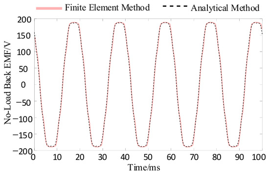
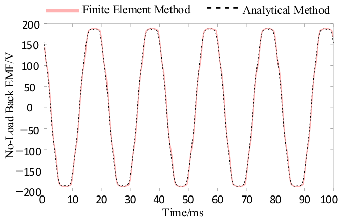
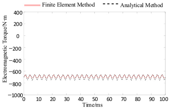
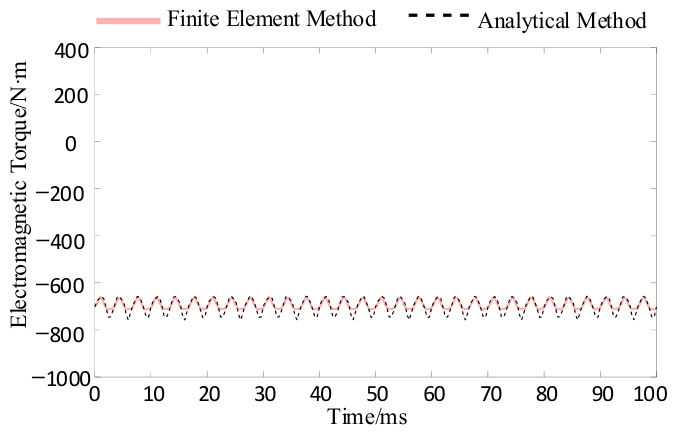
To further verify the reliability of the proposed model, comparative analyses of the back EMF and electromagnetic torque were also conducted, and the results are shown in Figure 13 and Figure 14.
Figure 13.
Back EMF waveform of Phase A.
Figure 14.
Electromagnetic torque waveform.
As can be observed from the no-load back EMF waveforms in Figure 13, the results calculated by the finite element method and the analytical method exhibit a high degree of consistency in overall trend. Good agreement is achieved in terms of periodic variation, waveform shape, and the positions of the main characteristic points. However, some discrepancies still exist near the peak values of the waveform. Overall, these differences have a negligible impact on the evaluation of the no-load back EMF, which verifies the accuracy of the proposed analytical method in describing the no-load back EMF characteristics of the motor.
As can be seen from the electromagnetic torque waveforms in Figure 14, the results obtained by the two methods are generally consistent in overall trend, although some differences exist in local details. These differences mainly arise from the combined effects of magnetic field distortion and the slotting effect, which cause the internal magnetic field distribution of the motor to deviate from the ideal sinusoidal form. The finite element method can more accurately capture the local variations in the complex electromagnetic field, whereas the analytical method is typically based on the fundamental component of the magnetic field and therefore has certain limitations in reflecting the small torque fluctuations caused by higher-order harmonics and magnetic field distortion.
4.3. Computational Time Comparison of FEM and Analytical Methods
To further assess the computational efficiency of the proposed analytical method, a comparison is made between the analytical method and the finite element method in terms of computation time for air-gap flux density, back EMF, and electromagnetic torque. Table 2 presents the time consumption for both methods during the aforementioned calculations.
Table 2.
Comparison of computational time for electromagnetic performance between the two methods.
As shown in Table 2, the computational time for the analytical method is significantly lower than that of FEM when calculating electromagnetic performance. In complex electromagnetic calculations, the analytical method avoids the cumbersome processes of mesh generation and iterative solving by directly solving the mathematical model, thereby significantly reducing computation time. This demonstrates that the analytical method, while ensuring sufficient computational accuracy, can greatly reduce computation time and is suitable for applications requiring a fast response.
5. Conclusions
In the operation of hydro-generators, the calculation of air-gap flux density faces the challenge of simultaneously accounting for the combined effects of the slotting effect and rotor salient-pole characteristics. In this paper, a new method for calculating air-gap flux density, integrating both the slotting effect and rotor salient-pole features, is proposed. The results reveal the following:
- (1)
- The analytical method is capable of simultaneously considering the combined effects of the slotting effect and rotor salient-pole characteristics on the air-gap flux density. By calculating the flux density distribution for each phase, the analytical method provides fundamental data for further analysis of the motor’s no-load back EMF, electromagnetic torque, and other performance indicators.
- (2)
- The analytical method can further compute key motor performance indicators, such as no-load back EMF and electromagnetic torque, providing quantifiable data support for analyzing the operating conditions and performance changes in the hydro-generator under eccentric fault conditions. It also offers a methodological reference for rapid modeling and performance prediction studies involving similar multi-factor coupling.
- (3)
- The computational time required by the analytical method is significantly lower than that of the mesh-based finite element method, enabling the rapid output of air-gap flux density and related motor performance parameters. This meets the demands for fast modeling and performance analysis.
Author Contributions
Conceptualization, Y.L. and Y.Z.; methodology, J.W., B.R. and J.L.; software, Y.L.; validation, Y.P.; resources, Y.L. and Y.Z.; data curation, Z.C.; writing—original draft preparation, Y.Z.; writing—review and editing, Y.Z.; project administration, Y.Z.; funding acquisition, Y.L. All authors have read and agreed to the published version of the manuscript.
Funding
This work is supported by the Scientific Research Project of China Yangtze Power Co., Ltd. (Z152402078), and the Hubei Natural Science Foundation (2024AFD353).
Data Availability Statement
The data presented in this study are available from the corresponding author upon reasonable request.
Acknowledgments
The authors would like to thank China Yangtze Power Co., Ltd. for providing valuable technical support and assistance during this research.
Conflicts of Interest
Authors Youping Li, Junqing Wang, Bo Ren and Jinwen Luo are employed by China Yangtze Power Co., Ltd. This work is supported by China Yangtze Power Co., Ltd. The funding sponsors had no role in the design of the study; in the collection, analyses, or interpretation of data; in the writing of the manuscript; or in the decision to publish the results.
References
- Wu, Y.; Liu, Y.; Bai, Y.; Fan, X. Online Diagnosis of Non-Roundness Fault in Rotor Magnetic Pole of a Hydro-Generator. IEEE Trans. Energy Convers. 2025, 40, 3059–3070. [Google Scholar] [CrossRef] [Scilit]
- Borkowski, D.; Węgiel, T.; Kisielewski, P.; Liszka, D. Universal Modular Permanent Magnet Synchronous Generator for Small Low-Head Hydropower Plants. IEEE Trans. Energy Convers. 2023, 38, 2884–2894. [Google Scholar] [CrossRef] [Scilit]
- Kumari, R.; Chelliah, T.R. Impact Analysis of Sensor Cyber-Attacks on Grid-Tied Variable Speed Hydropower Plants. IEEE Trans. Ind. Appl. 2023, 59, 7725–7734. [Google Scholar] [CrossRef] [Scilit]
- Im, J.-H.; Kang, J.-K.; Hur, J. Static and Dynamic Eccentricity Faults Diagnosis in PM Synchronous Motor Using Planar Search Coil. IEEE Trans. Ind. Electron. 2023, 70, 9291–9300. [Google Scholar] [CrossRef] [Scilit]
- Gong, Z.; Desenfans, P.; Pissoort, D.; Hallez, H.; Vanoost, D. Multiphysics Coupling Model to Characterise the Behaviour of Induction Motors With Eccentricity and Bearing Faults. IEEE Trans. Energy Convers. 2024, 39, 146–159. [Google Scholar] [CrossRef] [Scilit]
- Alimardani, R.; Rahideh, A.; Kia, S.H. Mixed Eccentricity Fault Detection for Induction Motors Based on Time Synchronous Averaging of Vibration Signals. IEEE Trans. Ind. Electron. 2024, 71, 3173–3181. [Google Scholar] [CrossRef] [Scilit]
- Chen, Z.; Wang, F.; Fan, C.; Ling, Z.; Li, Z.; Wang, Q. Analysis of Rotor Eccentricity Fault in IPMSM With Different Armature Winding Structures. IEEE Trans. Magn. 2023, 59, 8100410. [Google Scholar] [CrossRef] [Scilit]
- Bang, T.-K.; Shin, K.-H.; Lee, J.-I.; Lee, H.-K.; Cho, H.-W.; Choi, J.-Y. Electro-Mechanical Characteristics Analysis and Experimental Study of PMSM According to Rotor Eccentricity. IEEE Trans. Magn. 2022, 58, 8103205. [Google Scholar] [CrossRef] [Scilit]
- Zhan, H.; Liu, W.; Lyu, Z.; Niu, S.; Wu, L.; Chau, K.T. Eccentricity Fault Diagnosis in Multimodule Permanent Magnet Synchronous Machines Based on Zero-Sequence Voltage Component. IEEE Trans. Ind. Electron. 2025, 72, 12332–12342. [Google Scholar] [CrossRef] [Scilit]
- Song, J.; Qian, L.; Wu, X.; Wu, J.; Lu, S.; Wang, X. DPMSLM Eccentricity Fault Detection Based on Multiview of Mystery Curve Transformation and Deep Feature Extraction. IEEE Sens. J. 2024, 24, 18219–18231. [Google Scholar] [CrossRef] [Scilit]
- Ren, J.; Wang, X.; Zhao, W. Magnetic Field Prediction of the Saturated Surface-Mounted Permanent Magnet Synchronous Machine With Rotor Eccentricity. IEEE Trans. Ind. Electron. 2022, 69, 7756–7766. [Google Scholar] [CrossRef] [Scilit]
- Xue, L.; Luo, L. Semi-Analytical Calculation of the Unsaturated Magnetic Field Distribution of a Slotted Spoke-Type Interior Permanent Magnet Machine With Conformal Mapping Method. IEEE Trans. Magn. 2022, 58, 8104810. [Google Scholar] [CrossRef] [Scilit]
- Lv, G.; Zhi, R.; Cui, L.; Zhang, Z.; Liu, Y. Analysis on the Air-Gap Magnetic Flux Density and Propulsion of the TFLSM Considering Cogging Effect. IEEE Trans. Magn. 2023, 59, 8100507. [Google Scholar] [CrossRef] [Scilit]
- Cheng, W.; Cao, G.; Deng, Z.; Xiao, L.; Li, M. Torque Comparison Between Slotless and Slotted Ultra-High-Speed AFPM Motors Using Analytical Method. IEEE Trans. Magn. 2022, 58, 8101805. [Google Scholar] [CrossRef] [Scilit]
- Liu, C.; Zuo, S.; Hu, S.; Qu, S.; Wu, Z. Quasi-3-D Nonlinear Analytical Modeling of Magnetic Field in Axial-Flux Switched Reluctance Motors. IEEE Trans. Magn. 2022, 58, 8104212. [Google Scholar] [CrossRef] [Scilit]
- Lee, J.-I.; Shin, K.-H.; Seo, S.-W.; Bang, T.-K.; Shin, S.-H.; Kim, K.-H.; Bird, J.; Choi, J.-Y. Electromagnetic Performance Analysis and Experimental Verification Considering the End Effect of Linear Magnetic Gears Using Subdomain-Based Analytical Method. IEEE Trans. Magn. 2021, 57, 8000605. [Google Scholar] [CrossRef] [Scilit]
- Hong, J.; Wang, S.; Sun, Y.; Cao, H. A High-Precision Analytical Method for Vibration Calculation of Slotted Motor Based on Tooth Modeling. IEEE Trans. Ind. Appl. 2021, 57, 3678–3686. [Google Scholar] [CrossRef] [Scilit]
- An, Y.; Ma, C.; Zhang, N.; Guo, Y.; Degano, M.; Gerada, C.; Li, Q.; Zhou, S. Open-Circuit Air-Gap Magnetic Field Calculation of Interior Permanent Magnet Synchronous Motor With V-Shaped Segmented Skewed Poles Using Hybrid Analytical Method. IEEE Trans. Magn. 2021, 57, 8108309. [Google Scholar] [CrossRef] [Scilit]
- Cai, H.; Du, T.; Dong, F.; Chen, Z.; Shen, D.; Zou, Y.; Xu, M. Triboelectric and electromagnetic hybrid generators for ocean energy harvesting. Nano Energy 2024, 132, 110363. [Google Scholar] [CrossRef] [Scilit]
- Zuo, F.; Liu, J.; Ren, Y.; Wang, L.; Wen, Z. A Reliable Bolt Key-Points Detection Method in Industrial Magnetic Separator Systems. IEEE Trans. Instrum. Meas. 2025, 74, 5015710. [Google Scholar] [CrossRef] [Scilit]
- Guo, Y.; Wang, D.; Liu, D.; Wu, X.; Chen, J. Magnetic circuit calculation of non-salient pole synchronous generator based on distributed magnetic circuit method. In Proceedings of the 2011 International Conference on Electrical Machines and Systems, Beijing, China, 20–23 August 2011. [Google Scholar]
- Li, Y.; Lu, Q.; Zhu, Z.Q.; Wu, D.; Li, G. Superposition Method for Cogging Torque Prediction in Permanent Magnet Machines With Rotor Eccentricity. IEEE Trans. Magn. 2016, 52, 8103710. [Google Scholar] [CrossRef]

Disclaimer/Publisher’s Note: The statements, opinions and data contained in all publications are solely those of the individual author(s) and contributor(s) and not of MDPI and/or the editor(s). MDPI and/or the editor(s) disclaim responsibility for any injury to people or property resulting from any ideas, methods, instructions or products referred to in the content. |
© 2026 by the authors. Licensee MDPI, Basel, Switzerland. This article is an open access article distributed under the terms and conditions of the Creative Commons Attribution (CC BY) license.