


Abstract
Fast charging of lithium-ion battery packs involves a compromise between charging speed, temperature rise, and aggressive current profiles that may accelerate battery degradation. This paper presents a current-stress-aware fuzzy logic control framework for safe fast charging of series-connected lithium-ion battery cells. The proposed controller uses a physically interpretable two-input, one-output fuzzy structure in which the highest cell-voltage difference, , and the lowest single-cell voltage, , are used to determine the charging-current command, . Unlike conventional fuzzy charging approaches that rely on manually selected membership functions or weighted single-objective tuning, the proposed method simultaneously optimizes the Gaussian membership-function parameters and the input/output scaling gains using a Pareto-based multi-objective optimization framework. The resulting design vector contains 21 decision variables, including 18 membership-function parameters and three scaling gains. Three conflicting objectives are minimized: the time required to reach 95% state of charge, the maximum temperature rise above the reference temperature, and a normalized current-stress index based on the integral of the squared charging current. The framework is implemented in MATLAB/Simulink using a three-cell Panasonic NCR18650PF lithium-ion battery pack model. The obtained Pareto front reveals the expected trade-off between fast charging and battery protection. The fastest solution reaches 95% SOC in 5440 s but produces the highest temperature rise and current-stress index, whereas the selected knee-point controller reaches the target in 6880 s while reducing the maximum temperature rise and current-stress index compared with the fastest solution. Robustness tests under variations in initial SOC, cell imbalance, initial temperature, capacity scaling, and internal-resistance scaling show that the knee-point controller maintains stable charging behavior and satisfies the imposed thermal safety constraint. The results demonstrate that the proposed current-stress-aware Pareto-optimized fuzzy controller provides a systematic and interpretable approach for balancing charging speed, thermal safety, and battery stress in lithium-ion battery fast charging.
1. Introduction
Lithium-ion batteries are used in portable electronics, electric vehicles, and stationary electric energy storage systems and off-grid power systems because of their high energy density, high power, long life, and low self-discharge. Despite these advantages, long charging time remains a major limitation. Conventional CC–CV charging is simple and reliable, but it is often conservative because the charging current must be limited to avoid overvoltage, excessive temperature rise, accelerated degradation, and safety concerns.
Fast charging is a multi-objective problem with a charging current increase leading to a reduction in time to reach a target SOC but an increase in heating, current-induced stress, lithium plating risk, and cell degradation. Thus, an effective fast-charging strategy should not focus solely on charging time. It should also account for thermal safety and current severity. The use of a squared-current stress objective is physically motivated because resistive losses and current-related stress increase with current magnitude. Thus, when a detailed electrochemical aging model is not included, the integral of the squared charging current provides a simple and interpretable stress-related proxy.
Several charging strategies have been developed to address this trade-off, including CC–CV charging, pulse charging, multistage constant-current charging, model-based optimal charging, data-driven optimization, reinforcement learning, and fuzzy logic control. Table 1 summarizes the main contributions of these approaches, their limitations, and the specific gaps addressed in this study.
Table 1.
Summary of related fast-charging approaches, limitations, and gaps addressed in this work.
As shown in Table 1, several limitations remain in the existing literature. First, many fuzzy charging methods rely on manually selected membership functions, fixed scaling factors, or partial tuning. Second, optimized fuzzy chargers are often formulated using weighted single-objective cost functions, which produce only one compromise solution rather than a Pareto front. In particular, existing genetic-algorithm-based fuzzy charging studies mainly optimize charging time and temperature through a weighted fitness function, rather than treating the objectives separately. For example, Károlyi et al. [16] optimized fuzzy charging-controller parameters using a genetic algorithm, but the method produced a single compromise solution and did not explicitly include a current-stress indicator as an independent objective. Third, most fuzzy fast-charging studies focus mainly on charging time and temperature, while current-stress severity is not explicitly included as an optimization objective. Fourth, although the voltage-difference signal and the lowest single-cell voltage are physically meaningful for series-connected packs, they have not been fully integrated with simultaneous optimization of membership functions and scaling gains. Finally, robustness is often evaluated only after the nominal controller is selected, if it is evaluated at all.
To address these gaps, this paper proposes a current-stress-aware Pareto-optimized fuzzy logic charging framework for series-connected lithium-ion batteries. The proposed controller uses a two-input, one-output Mamdani fuzzy inference system in which and are used to determine the normalized charging-current command. The fuzzy membership-function parameters and input/output scaling gains are optimized simultaneously using NSGA-II. The resulting design vector contains 21 decision variables, including 18 Gaussian membership-function parameters and three scaling gains. The optimization problem minimizes three objectives: the time required to reach 95% SOC, the maximum temperature rise above the reference temperature, and a normalized current-stress index based on the integral of . Unlike weighted single-objective fuzzy charging approaches, the proposed Pareto-based formulation keeps these objectives separate, allowing the trade-off between charging speed, thermal safety, and current stress to be evaluated directly.
The main contributions of this paper are summarized as follows:
- 1.
- A Pareto-based multi-objective optimization framework is developed for tuning a fuzzy fast-charging controller for series-connected lithium-ion cells.
- 2.
- The fuzzy controller retains the physically interpretable inputs and , which represent cell-voltage imbalance and the lowest single-cell voltage in the battery string.
- 3.
- The membership-function parameters and input/output scaling gains are optimized simultaneously instead of being manually selected or partially tuned.
- 4.
- A normalized current-stress objective, , based on the integral of is introduced as a separate optimization objective to represent fast-charging severity and strengthen the trade-off between charging speed and battery stress.
- 5.
- The selected knee-point controller is tested under ten robustness scenarios, including initial SOC variation, cell-to-cell SOC imbalance, initial-temperature variation, reduced capacity, increased internal resistance, and a combined off-nominal condition.
The scope of this study is limited to simulation-based optimization using a MATLAB/Simulink battery model. Therefore, the current-stress objective is used as a degradation-related proxy rather than a full electrochemical aging model. In addition, the study focuses on a specific lithium-ion cell type and a three-cell series-connected battery configuration. The robustness analysis evaluates the selected knee-point controller under representative initial-condition and parameter variations, but it does not replace experimental validation or long-term aging tests. Experimental validation, extension to larger battery packs, incorporation of detailed aging models, and robust multi-objective optimization under uncertainty are left for future work. Therefore, the reported results should be interpreted as simulation-based validation of the proposed controller-design framework. Practical implementation will require hardware-in-the-loop or battery test-bench experiments to evaluate measurement noise, converter dynamics, sensor delay, dynamic polarization, cell-to-cell manufacturing variation, and aging-related changes under real operating conditions.
2. Simulation Model of the Proposed Battery Charging System
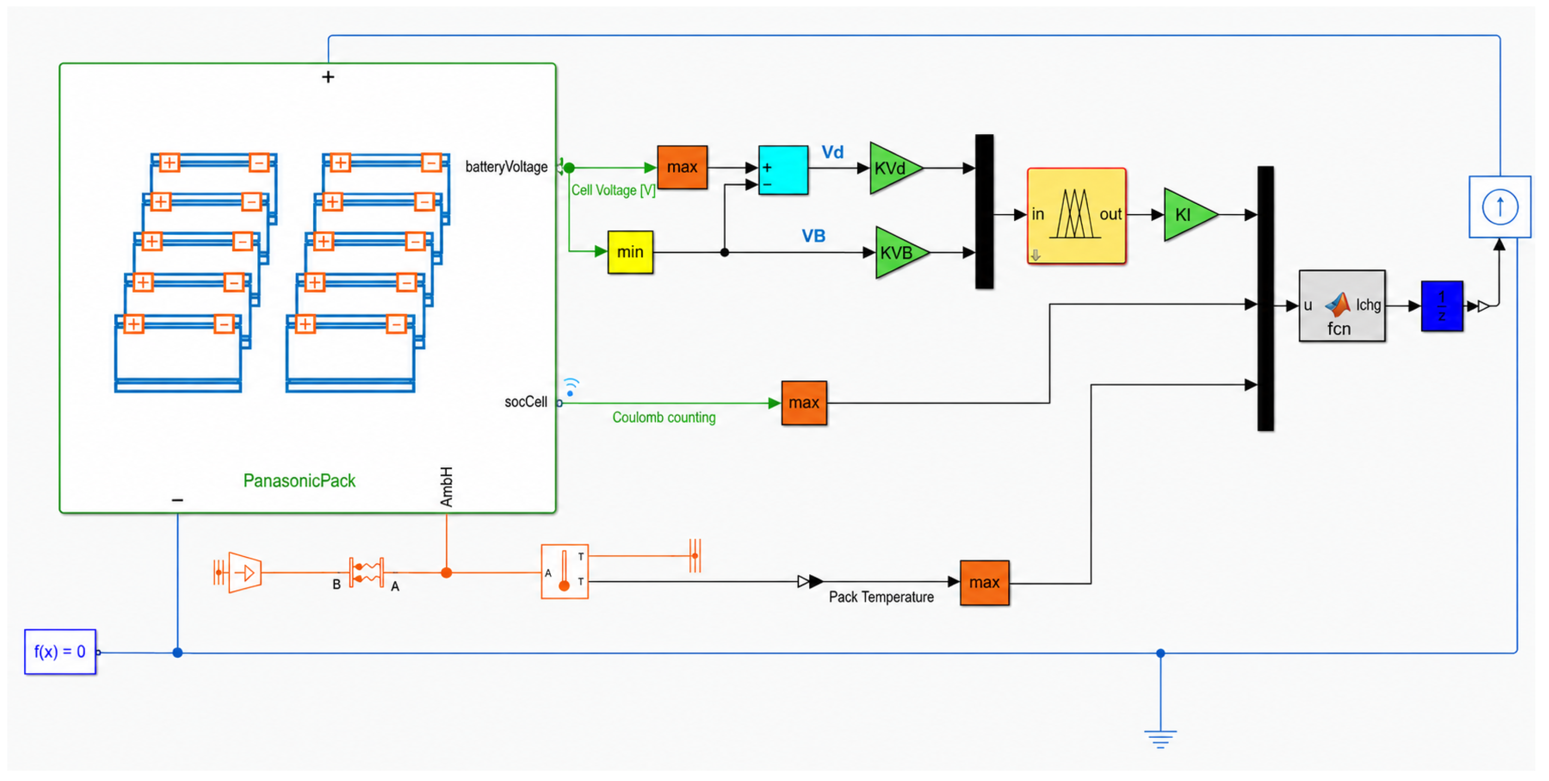
Figure 1 presents the model implemented in MATLAB/Simulink for performance analysis of the proposed fuzzy-logic-based fast-charging technique. The proposed charging model is based on a closed-loop approach for a Panasonic NCR18650PF lithium-ion battery pack. The model comprises the three-cell series-connected battery pack, the voltage processing blocks, the fuzzy logic controller, the current-limiting and safety-supervision section, a unit-delay block, and the controlled current source block. Since the battery pack consists of three cells connected in series, the same charging current flows through all cells. However, the individual cell voltages and cell states-of-charge may evolve differently during charging because of cell-level dynamic differences and initial-condition variations.
Figure 1.
MATLAB/Simulink R2026a model of the proposed fuzzy-logic-based battery charging system. The model includes the Panasonic NCR18650PF battery pack, voltage-processing blocks for and , input scaling gains and , the fuzzy logic controller, the output scaling gain , current-limiting and safety-supervision logic, a unit-delay block , and a controlled current source. The arrows indicate the signal-flow direction between the Simulink blocks, while the blue physical connections represent the Simscape electrical circuit.
The battery pack subsystem provides the main feedback signals required by the controller, including the individual cell voltages, the cell state-of-charge signal, and the pack temperature. The individual cell-voltage vector is processed using maximum and minimum blocks. The maximum cell voltage, , and minimum cell voltage, , are used to define the cell-voltage difference as
while the lowest single-cell voltage is defined as
The two signals and are selected because they provide complementary information about the pack condition. While indicates the cell-to-cell voltage imbalance, indicates the lowest voltage cell of the string. This is important to note as, in a series-connected battery pack, the SOC of the weakest cell can constrain the allowable charging behavior and usable pack capacity. The input structure follows fuzzy fast-charging control, where and are used to compute the charging-current command for a series-connected lithium-ion battery string [15].
Before being passed through the fuzzy logic controller, the two voltage feedback signals are scaled with and . The voltage difference that is forwarded to the controller is given by
and the normalized lowest-cell-voltage input is given by
These two normalized signals are then multiplexed and passed through the fuzzy logic controller, which converts the signals to the normalized charging-current command . This command is then scaled by the output gain to generate the fuzzy current request:
In this study, the scaling gains , , and are included in the optimization design vector together with the membership-function parameters. Therefore, the optimizer tunes not only the fuzzy membership functions but also the sensitivity of the controller to the voltage-based inputs and the magnitude of the resulting current command.
The model also includes state-of-charge and thermal feedback. The socCell signal is processed to obtain the SOC signal used by the charging-supervision logic. The battery pack temperature is obtained from the pack-temperature measurement path and is used to determine the maximum pack temperature, . The battery temperature should also remain in the acceptable charging temperature range, as lithium-ion batteries are sensitive to thermal cycling during charging. For example, for the Panasonic NCR18650PF cell, the charging temperature range is recommended to be approximately to ( to ) [18]. For the implemented model, the lower temperature cutoff is set to and the upper cutoff is set to approximately . This temperature window is enforced to prevent charging under conditions that may increase degradation risk, reduce cycle life, or create unsafe operating conditions.
The final applied charging current is determined by the fuzzy current request, the SOC signal, and the maximum pack temperature. The implemented logic first limits the fuzzy current request to the maximum allowable charging current of . Charging is then stopped if the SOC reaches unity or if the pack temperature leaves the allowable charging-temperature window. The current-limiting and safety-supervision logic can be written as
This logic prevents the charging current from exceeding during simulation and stops charging when the SOC or temperature constraints are violated. The current limit of corresponds approximately to a charging-rate interpretation based on the typical NCR18650PF capacity of about . This value is also close to the standard charging current of approximately reported for CC–CV charging at [18]. Therefore, the selected current limit provides a practical upper bound for the optimized controller and prevents the optimizer from reducing charging time by selecting unrealistically aggressive current commands.
The applied current command is passed through a unit-delay block before being applied to the controlled current source. The unit-delay block is included for two reasons: First, it represents the one-sample computational delay that naturally occurs in a discrete-time digital charging controller, where the current command is computed from measured signals and applied at the next sampling instant. Second, it improves the numerical properties of the Simulink closed-loop model by preventing direct feedthrough from measured battery states to the current source on the same time step. For instance, the unit-delay block in Simulink delays the signal by one sample. This is analogous to the discrete-time operator [19]. In feedback systems, direct feedthrough paths can create algebraic loops. A typical method of breaking such loops, and improving simulation stability [20], is to insert a unit-delay block.
The controlled current source is connected to the positive and negative terminals of the three-cell Panasonic NCR18650PF battery pack and injects the commanded charging current into the battery. The Simscape electrical network also requires an electrical reference and a solver configuration block in order to enable physical domain simulation of this model. Overall, this model represents a closed-loop battery charging system, where the fuzzy controller decides the requested current depending on the cell-voltage imbalance and the lowest cell voltage, and the current-limiting block enforces the current, SOC, and temperature limits. This simulation structure allows the proposed optimization framework to assess the charging time, temperature rise, and severity-of-current-stress values for the same operating conditions.
Fuzzy Logic Controller Structure
The proposed charging system uses a two-input, one-output Mamdani fuzzy inference system (FIS). As described in the previous section, the FIS inputs are the normalized voltage-difference signal, , and the normalized lowest-cell-voltage signal, . The normalized current is the FIS output, and it is later scaled to obtain the current requested by the fuzzy controller. This input–output structure follows the fuzzy fast-charging strategy in which the cell-voltage difference and lowest cell voltage in a string are used to control the charging current for a series-connected battery string [15].
To define the input and output linguistic variables, the FIS uses five linguistic terms: very small (VS), small (S), medium (M), large (L), and very large (VL). Each of the linguistic terms is defined by a Gaussian membership function. For a normalized variable , the kth membership function is defined as
where is the Gaussian width and is the center of the kth membership function. The center determines the location of the corresponding linguistic region on the normalized universe of discourse, while controls the width and overlap of the membership function with adjacent linguistic regions.
The Mamdani FIS settings used in the proposed controller are listed in Table 2. The controller uses the minimum operator for the AND operation and implication, the maximum operator for aggregation, and centroid defuzzification. These choices are consistent with the max–min inference and center-of-gravity defuzzification approach used in the reference fuzzy fast-charging methodology [15].
Table 2.
Mamdani FIS settings used in the proposed controller.
The fuzzy rule base is assumed to be fixed during the optimization process, as presented in Table 3. In the table, the rules are organized as rows in terms of and columns in terms of . The cell contents hold the output linguistic value of . The rule base increases the charging-current command as the cell-voltage difference becomes larger, while still accounting for the lowest cell voltage in the string. Keeping the rule base fixed preserves the physical interpretability of the controller, while optimizing the membership functions and gains allows the input–output mapping to be tuned systematically.
Table 3.
Fuzzy rule base for the normalized charging-current command.
Each rule can be expressed in the general form
where , , and are selected from the linguistic set . The firing strength of each rule is calculated using the minimum operator:
The implied output of each rule is obtained by clipping the corresponding output membership function:
The aggregated output fuzzy set is then obtained using
Finally, the normalized charging-current command is computed using centroid defuzzification:
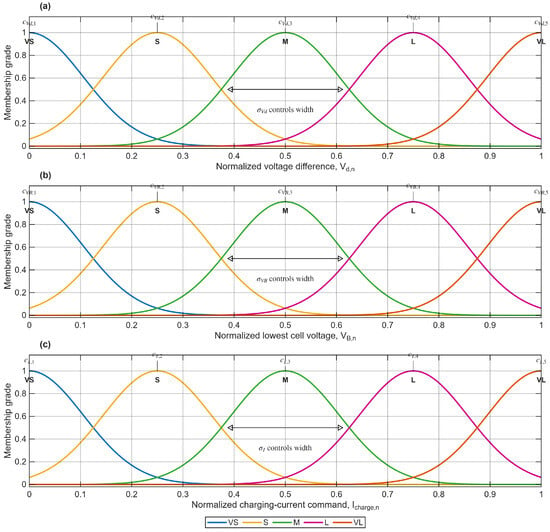
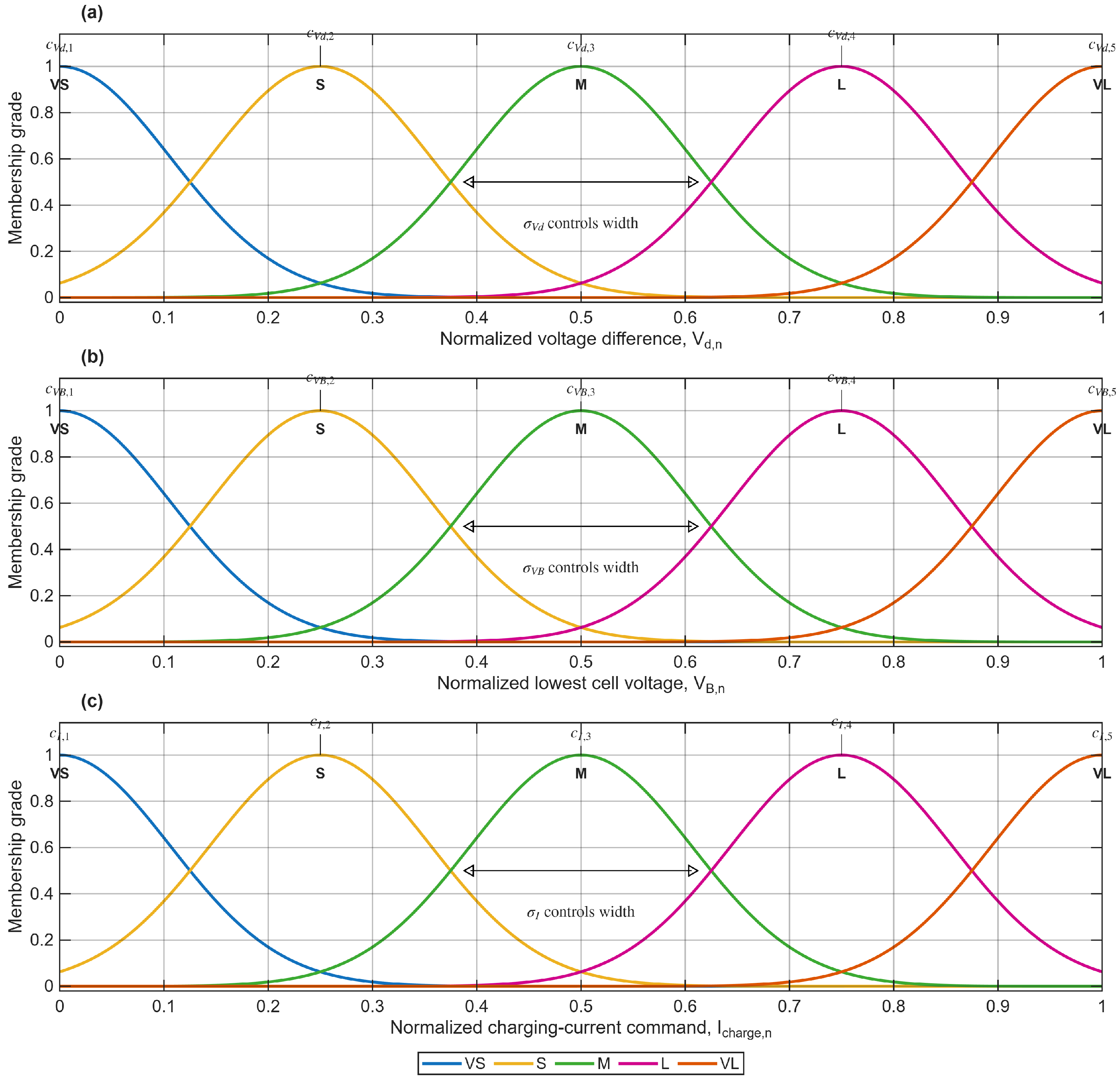
The Gaussian membership functions used for the two normalized inputs and and the normalized output are shown in Figure 2. There are five linguistic terms for each fuzzy set of the inputs/outputs: VS, S, M, L, and VL, respectively. The centers define the locations of these linguistic regions, while the width parameter controls the spread and overlap between adjacent membership functions. These center and width parameters are included in the optimization design vector and are tuned by the multi-objective optimization algorithm described in the next section.
Figure 2.
Gaussian membership functions used for the fuzzy logic controller: (a) normalized voltage-difference input, ; (b) normalized lowest-cell-voltage input, ; and (c) normalized charging-current command, . The centers determine the locations of the VS, S, M, L, and VL linguistic sets, while the corresponding width parameter controls the spread and overlap of the Gaussian functions.
The in Figure 2a indicates the voltage imbalance across the three series-connected cells. The smaller the value, the more homogeneous the pack, and the larger the value the greater differences between the maximum and minimum values of the cell voltage. As shown in Figure 2b, means the voltage of the least charged cell, which acts as the bottleneck during charging operations. The output membership function of the charging current is shown in Figure 2c. It affects the final defuzzified charging-current command. Thus, membership-function parameters can be identified so that the proposed controller optimizes the charging-current profile with respect to the charging speed, temperature rise, and current stress.
3. Multi-Objective Optimization
Many engineering design problems require the simultaneous optimization of multiple, often conflicting, performance objectives. Such problems can be formulated as multi-objective optimization problems when two or more performance metrics must be improved simultaneously [21,22,23,24]. This kind of conflict is most important in the context of battery fast-charging applications, as a fast charge requires a more aggressive current profile, while a lower thermal load and less current stress result in a less aggressive current profile. Thus, one design cannot suit all purposes. Instead, for an MOP, the solution set is a collection of trade-off solutions, where different trade-offs are made between the objectives.
Let be the decision variable vector to be optimized; in this work, denotes the tunable fuzzy charging controller parameters, such as membership-function parameters and scaling gains. In general, this MOP can be formulated as
where is the objective vector, the ith objective function is given by , and is the number of objectives. The feasible design domain is given by
where and are the functions for the inequality and equality constraints, respectively, and and are the number of inequality and equality constraints imposed by the optimization problem.
In contrast to a single-objective problem, the aim of an MOP is to find a set of non-dominated solutions according to the Pareto dominance relation [25]. For a minimization problem, a feasible solution is said to dominate another feasible solution if
and
Such points are called Pareto-optimal because no other feasible solution is better. The set of all Pareto-optimal solutions is called the Pareto set.
where denotes that dominates . The set of points in the objective space which corresponds to the vectors forming the Pareto set is called the Pareto front and is defined as
The Pareto front is useful for the designer to visualize the trade-off between the objectives and, therefore, to choose the final controller with the design specifications of interest.
There are several algorithms attempting to approximate Pareto-optimal solutions using evolutionary or swarm algorithms, such as NSGA-II, SPEA2, SMS-EMOA, MOPSO, and MOEA/D [26,27,28,29]. Further strategies around improving the convergence and diversity in multi-objective optimization problems include non-dominated sorting and elitism, as in NSGA-II [26], and improved fitness assignment and density estimation, as in SPEA2 [27]. MOEA/D decomposes the MOP into several scalar optimization problems that are solved simultaneously [29]. Surveys and tutorials on MOP, goal programming, EMO, and benchmarking platforms can be found at [28,30,31,32,33].
Instead of manually adjusting the fuzzy charging controller’s membership functions and gains, these parameters were determined by multi-objective optimization. The aim was to achieve an optimal trade-off between the charging time, thermal behavior, and the severity of the charging-current stress. A Pareto-based formulation is appropriate in this case because improving one objective, such as charge time, tends to worsen another, such as temperature rise or current stress. Therefore, a Pareto front provides a systematic basis for selecting a fuzzy charging controller that balances fast charging, thermal safety, and current stress.
Design Variables, Bounds, and Objective Functions
To apply NSGA-II, the fuzzy charging controller should first be parameterized as a finite-dimensional design vector. In this work, the optimization does not modify the fuzzy rule base. Instead, it tunes the shapes and locations of the membership functions and the scaling gains that connect the Simulink battery model to the normalized fuzzy inference system. This preserves the interpretability of the original fuzzy charging structure while allowing the optimizer to improve the controller performance.
The complete design vector is defined as
Thus, the optimization problem has 21 decision variables: the first 18 decision variables are the parameters of the Gaussian membership functions of the normalized fuzzy inference system, and the last three are the input/output gains. The parameters , , and , are the respective Gaussian widths of the , , and membership functions, while the parameters , , and , are the respective centers of the membership functions of the five linguistic variables VS, S, M, L, and VL. Additionally, the gains and adjust the sensitivity of the fuzzy controller for the input variables of voltage difference and lowest cell voltage, and the gain adjusts the current request for a given normalized fuzzy output.
The optimization is subject to simple bound constraints:
where the lower and upper bounds are selected as
and
Table 4 describes the design variable bounds. Because all FIS variables are normalized to , the same center bounds are used for the input and output membership functions. These bounds preserve the linguistic ordering of the fuzzy sets while still allowing the optimizer to adjust their locations. For example, the center of the VS (very small) fuzzy set can only move close to the beginning of the normalized domain, and the VL can only move in the opposite direction. The S, M, and L centers can be slightly moved from their nominal values of 0.25, 0.50, and 0.75, to provide some tuning while still maintaining a meaningful fuzzy partition.
Table 4.
Bounds of the fuzzy-controller design variables.
Finally, bounds on the Gaussian widths should also be taken into consideration. As pointed out above, small values of will result in compact membership functions and, therefore, in a very steep fuzzy control surface, while excessively large values of will result in an overlap of the linguistic regions and, therefore, non-distinction of the fuzzy sets. Thus, to allow the optimizer the control of the smoothness and overlap of the membership functions without producing an excessively high discontinuity or flat fuzzy surface, the interval was used. For the controller gains, , the interval was chosen to prevent the gain from becoming negative, but still allowing the optimizer to increase or reduce the sensitivity of the controller.
For each candidate design vector , the corresponding FIS is constructed and inserted into the MATLAB/Simulink charging model. The charge current , the maximum battery-pack temperature , and the state-of-charge of the battery pack can then be determined through the simulation. The charging target is defined as
The time required to reach this target is
If the battery does not reach the target SOC during the simulation, the candidate controller is penalized by assigning a large objective vector:
The first objective is the charging time,
This objective encourages fast charging by favoring controllers that reach 95% SOC in a shorter time. The second objective is the maximum temperature rise above the reference temperature:
where
This objective is included because temperature is a critical safety and aging factor during lithium-ion battery charging. According to the charge specifications of the Panasonic NCR18650PF, charging should be done within the stated temperature ranges and with a limited CC–CV charging rate [18]. The literature shows that high charging current and temperature may lead to degradation and safety issues in fast charging [1,2]. The third objective is a normalized current-stress index:
where
The squared-current term provides a simple current-stress proxy because resistive losses and current-related stress increase with current magnitude. As the charging current increases, generally decreases, while increases. Therefore, discourages unnecessarily aggressive current commands. It should be noted that is not a direct electrochemical aging model. It does not explicitly quantify lithium plating, SEI growth, capacity fade, or resistance growth. Instead, it is used as a simple current-severity indicator to reduce unnecessarily aggressive charging behavior when detailed aging-state information is not available. Thus, is taken to correspond to a conservative estimate of the charging current for the Panasonic NCR18650PF used here and is close to the conventional CC–CV charging current range for this cell [18]; therefore, the full multi-objective optimization problem can be formulated as
In other words, the optimizer determines fuzzy-controller parameters such that the charging time is minimized, the maximum temperature increase is minimized, and the current stress is minimized. Due to the conflicting nature of these demands, the Pareto front shows the trade-off between fast charging and battery protection.
We used the Non-Dominated Sorting Genetic Algorithm II (NSGA-II), which simultaneously provides efficient non-dominated sorting, elitist selection, and diversity preservation using a technique called crowding distance [26]. The population size () is set to , where is the number of decision variables. Thus, individuals are needed to attain sufficient diversity to cover the controller design space and approximate the three-objective Pareto front.
The maximum number of generations was set to , which equates to evaluations of each candidate controller, excluding the initial population. This evaluation budget was a compromise between achieving a good Pareto front and the computing resources used to evolve the population, given that each objective-function evaluation requires a MATLAB/Simulink simulation. Previous studies have shown that population size and evaluation budget can strongly affect the ability of NSGA-II to approximate the Pareto front reliably [28,33,34].
The present problem has three objectives, which is within the range where NSGA-II is commonly effective. For problems with many objectives, larger populations or many-objective algorithms may be needed to maintain selection pressure and diversity [35]. However, for the three-objective fuzzy charging problem considered here, NSGA-II provides a suitable balance between robustness, implementation simplicity, and interpretability of the resulting Pareto front [36].
For reproducibility, the proposed framework can be implemented using MATLAB R2026a gamultiobj, PlatEMO, or the Python package pymoo, all of which provide NSGA-II-based or related multi-objective optimization implementations [33,37,38,39,40].
4. Pareto Optimization Results and Trade-Off Analysis
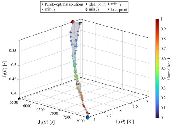
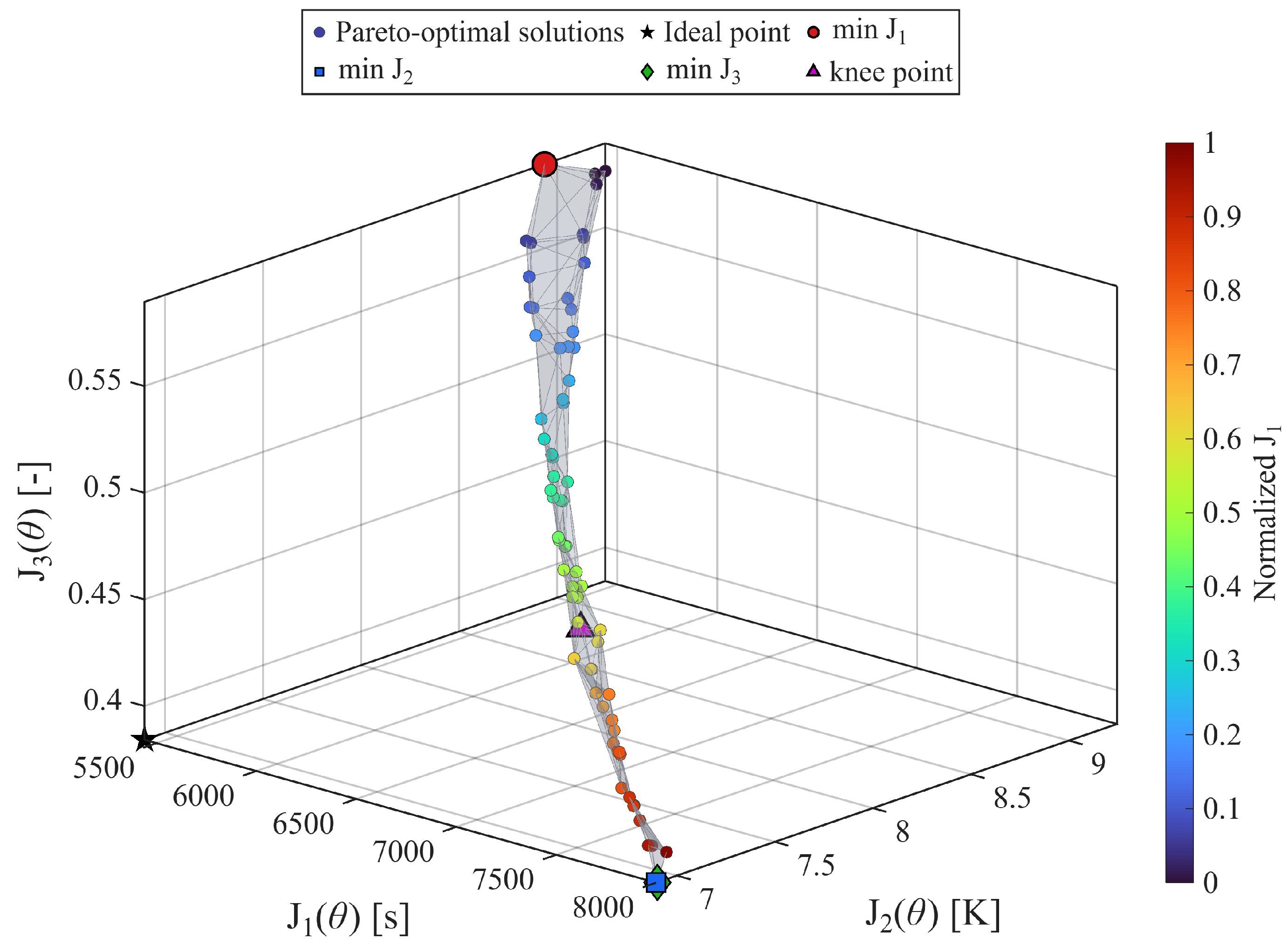
The NSGA-II optimization algorithm produced a set of non-dominated controllers, each representing a different trade-off between charging time, thermal response, and severity of current stress. This Pareto front in the three-dimensional objective space is provided in Figure 3. In the figure below, the three objective functions are depicted, whereby is the time to reach the target SOC, is the increase in temperature, and is the normalized current-stress index. Each corresponding point in the Pareto front is related to a single optimized controller design vector .
Figure 3.
Three-dimensional Pareto front obtained by NSGA-II for the proposed fuzzy fast-charging controller. The axes represent the charging-time objective , the maximum temperature-rise objective , and the normalized current-stress objective . The color bar represents the normalized value of for the Pareto-optimal solutions. The highlighted markers identify representative Pareto-optimal solutions, including the minimum-, minimum-, minimum-, and knee-point solutions. The knee point is selected as the Pareto-front solution with the smallest normalized Euclidean distance to the ideal point.
Further, a Pareto-optimal solution set shows the trade-off relationships among the three conflicting objectives. Controllers with a lower charging duration often operate at a higher commanded current level, which leads to higher thermal rise and current-stress index values. Conversely, controllers that reduce temperature rise or current stress usually require longer charging times. This behavior is expected because increasing the charging current accelerates SOC growth but also increases resistive heating and current-related stress. Thus, there may not be a controller that minimizes all three objectives simultaneously, and the best solution can be selected from the Pareto front considering the preferences between the charging time and the battery protection.
Some representative solutions are demonstrated in Figure 3. The minimum- solution is defined as the one that has the shortest charging time, while the minimum- and minimum- solutions are defined as the ones that have the lowest temperature rise and lowest current-stress index, respectively. It is known that the solution of the knee point is a compromise of all three objectives. For this paper, the knee point is chosen as the Pareto-front solution that is closest to the ideal point by the normalized Euclidean distance. The ideal point is the vector of the component-wise minima of , and . It does not have to be achievable by a feasible controller. To prevent the charging-time objective from biasing the distance calculations, it is normalized before computing the Euclidean distance, since its numerical value is larger than the others. The knee point chosen is therefore the Pareto-optimal controller that is closest to the ideal trade-off between fast charging, temperature safety, and current-stress reduction.
The objective values of the four points labeled in Figure 3 are listed in Table 5. It can be observed that, among the selected solutions, the minimum- controller achieves the desired state-of-charge level in the least time (within 5440 s) compared to the others. However, this faster charging response is obtained at the expense of the largest thermal and current-stress values, with a maximum temperature rise of and a normalized current-stress index of . This confirms the expected fast-charging trade-off: reducing the charging time requires a more aggressive current profile, which increases both thermal loading and current-related stress.
Table 5.
Objective values of selected Pareto-optimal charging solutions.
The minimum- and minimum- solutions both require to reach the target state-of-charge, making them the most conservative solutions among the selected cases. The minimum- solution gives the lowest maximum temperature rise, , while the minimum- solution gives a very similar temperature rise of . The two solutions also have the same reported current-stress index, , at the precision shown in the table. This close agreement indicates that, for the present battery model and constraints, reducing the current-stress objective also tends to reduce the thermal burden, since both objectives are strongly influenced by the magnitude and duration of the charging current.
In comparison with the minimum- solution, the knee-point solution’s charging time, maximum temperature rise, and current-stress index were 6880 , 7.6519 , and 0.45014, respectively. As a result, the charging time was increased by 1440 , the maximum temperature rise dropped by 1.2848 , and the current-stress index declined by 23.6%, respectively. The knee-point controller is a practical compromise between charging rate, thermal protection, and current stress.
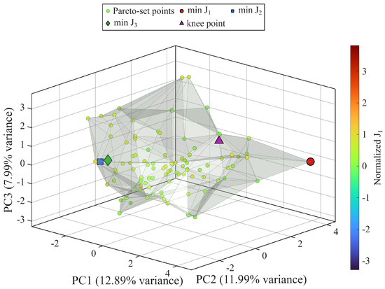
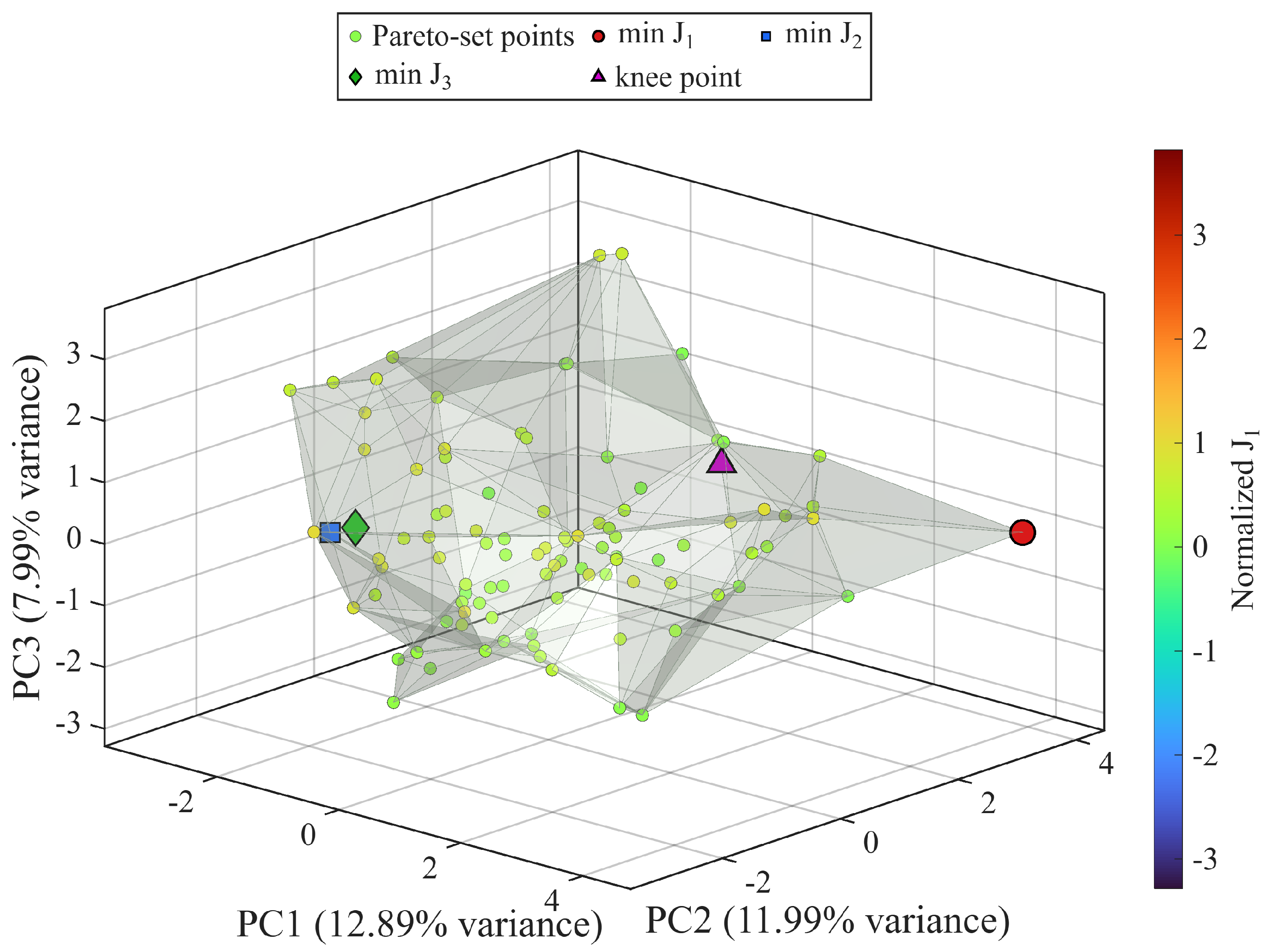
The corresponding Pareto set in the design-variable space is shown in Figure 4. The fuzzy controller optimized in this case is characterized by a 21-dimensional design vector, so we cannot display the full Pareto set. For this reason, PCA was used to project the vectors corresponding to the optimized designs onto the first three principal components. These components provide a compact low-dimensional visualization of the distribution of non-dominated controller parameters in the design space. In Figure 4, the same markers and color codes used in Figure 3 are used to visualize the Pareto set of representative solutions so that the controller parameter vector corresponding to each representative solution can be identified in the objective space.
Figure 4.
PCA-based three-dimensional projection of the Pareto set associated with the optimized fuzzy-logic-controller parameters. Since the Pareto set is defined in a 21-dimensional design-variable space, principal component analysis is used to project the optimized design vectors onto the first three principal components. The same highlighted solutions and color coding used in Figure 3 are retained to show the correspondence between objective-space performance and the associated controller-parameter vectors.
The projection of the Pareto set obtained by the use of PCA shows that the Pareto-optimal solutions form a highly regular area of the controller-design space. This indicates that the trade-offs observed in the objective space are associated with systematic changes in the fuzzy membership-function parameters and scaling gains. In particular, the highlighted solutions show that controllers optimized for fast charging, reduced temperature rise, reduced current stress, and balanced knee-point behavior correspond to different regions of the projected design space. This confirms that the proposed optimization framework not only optimizes for one controller but also provides different interpretable controller designs that can be selected according to the desired charging objective.
The design-parameter values for the four selected Pareto-optimal controllers are provided in Table 6. These parameters define the optimized Gaussian membership-function widths, membership-function centers, and input/output scaling gains of the fuzzy charging controller. Several trends can be observed from these values. The minimum- controller uses the largest output scaling gain, , which increases the effective charging-current command and explains the shorter charging time. This solution also uses a high lowest-cell-voltage scaling gain, , indicating that the weakest-cell voltage has a strong influence on the fuzzy controller. However, this aggressive scaling leads to increased thermal rise and current stress.
Table 6.
Design-parameter values of selected Pareto-optimal fuzzy charging controllers.
The minimum- and minimum- controllers use a lower output scaling gain, , which results in a less aggressive charging command. These solutions also use a much larger voltage-difference scaling gain, , compared with the fastest solution. This indicates that the controller becomes more sensitive to cell-voltage imbalance and, therefore, reduces the charging-current command more strongly when imbalance is present. This behavior is consistent with safer and less stressful charging.
Also, the scaling parameters of the knee-point controller—, , and —are midway between the aggressive minimum- controller and the conservative minimum- and minimum- controllers. These intermediate gain values further support the interpretation of the knee-point controller as a balanced tuning, since it maintains a moderate current command while still responding to cell-voltage imbalance and the lowest-cell-voltage signal.
In general, the results of the Pareto optimization show that no single fuzzy charging controller can minimize several conflicting objectives simultaneously. Instead, the proposed NSGA-II-based framework provides a family of interpretable Pareto-optimal controllers. The fastest controller is suitable when charging time is the dominant design priority, while the minimum-temperature and minimum-current-stress controllers are more suitable when conservative battery operation is desired. Among the selected solutions, the knee-point controller provides the most balanced performance and is therefore selected as the preferred controller for further analysis.
4.1. Time-Domain Response and Fuzzy-Controller Behavior
To further interpret the Pareto-optimal charging solutions, this section compares the time-domain responses of the minimum- solution, the minimum- solution, the minimum- solution, and the knee-point solution. These four controllers are respectively considered as the fastest charging case, the minimum-temperature-rise case, the minimum-current-stress case, and the balanced compromise solution. The reason for this is to link the trade-offs in objective space directly to the actual operation of the pack (state-of-charge, charge current, temperature, cell voltages, pack voltage, and fuzzy controller surfaces).
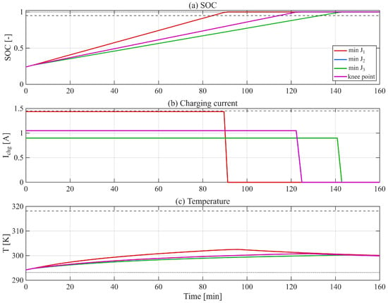
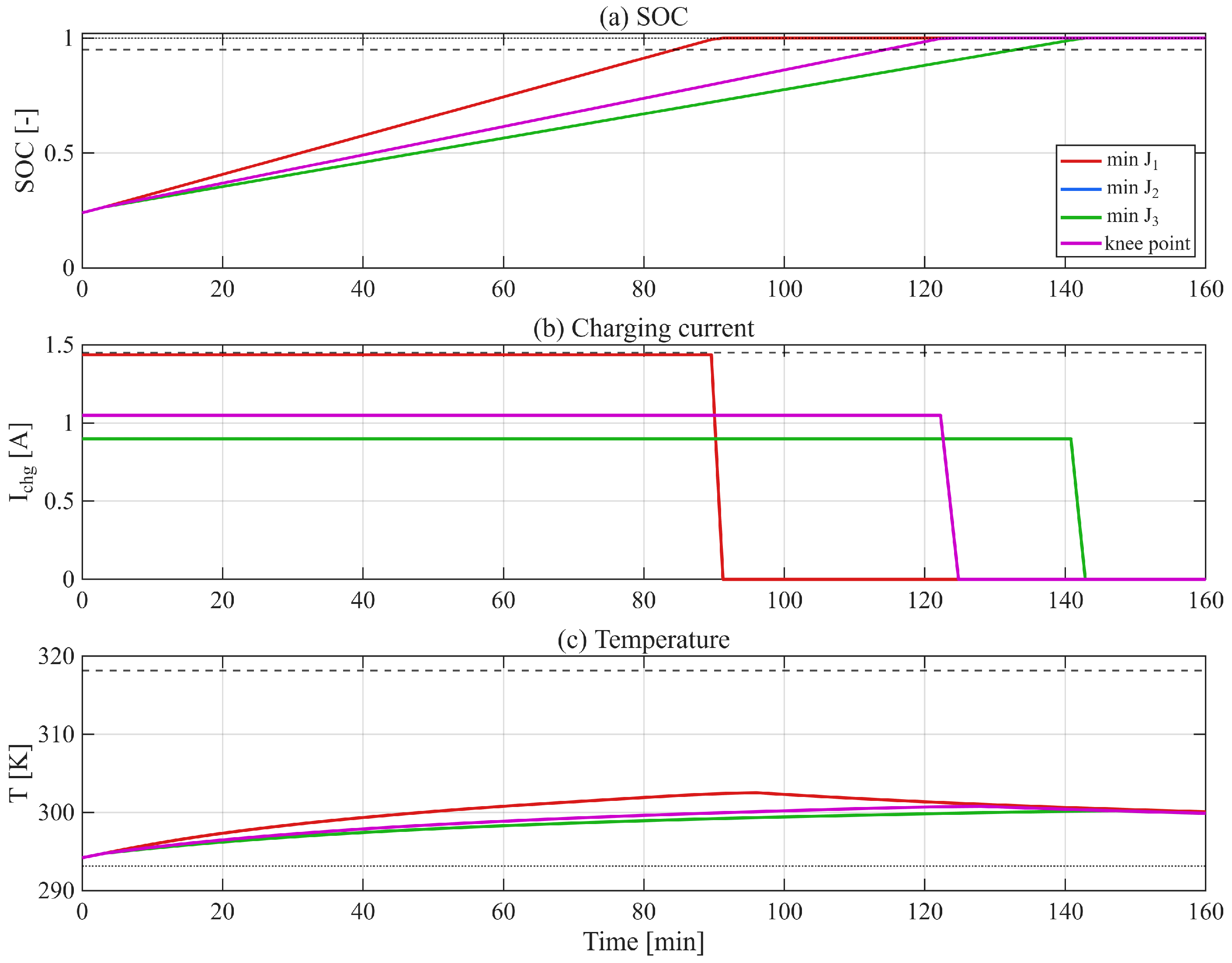
The state-of-charge, charging-current, and temperature responses of the selected Pareto-optimal controllers are shown in Figure 5. The minimum- reaches the target SOC fastest, consistent with its objective value of . This faster response is achieved by applying a higher charging current for a larger portion of the charging process, which also produces the highest temperature response among the selected controllers. In contrast, the minimum- and minimum- controllers use moderate charging currents and take a longer time to reach the maximum state-of-charge. This results in a lower temperature rise and a lower current-stress index; hence, the more conservative objective values. The knee-point controller is a compromise, charging faster than the minimum- and minimum- controllers, but less aggressively than the fastest possible controller with thermal and current-stress limits. The time-domain responses show that the knee point is a practical trade-off between the fast charging, thermal condition, and current stress.
Figure 5.
Time-domain responses of the selected Pareto-optimal fuzzy charging controllers: (a) state-of-charge, (b) charging current, and (c) battery temperature. The dotted horizontal lines indicate the main operating limits used in the simulation, including the target SOC, the maximum allowable charging current, and the temperature safety limit. The minimum- controller produces the fastest charging response by applying a larger current, while the minimum- and minimum- controllers are more conservative. The knee-point controller provides an intermediate response that balances charging time, temperature rise, and current stress.
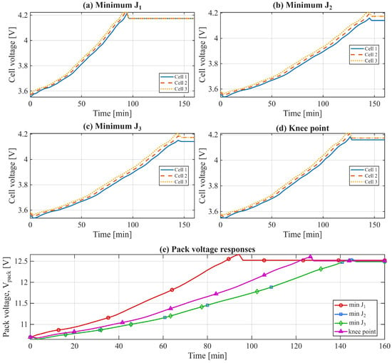
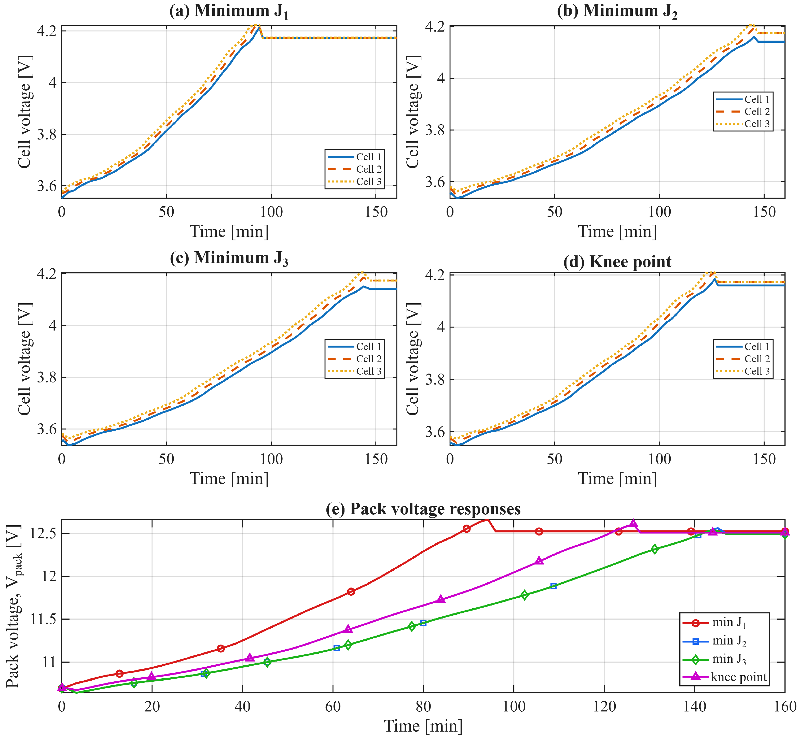
Figure 6 shows the battery cell-voltage responses for the four controllers being compared. The battery pack consists of three cells connected in series that carry the same charging current, but the cell voltages are different due to the different initial voltages of the cells and different dynamics. The cell voltages increase during charge and reach the top voltage region close to the end of charge. The minimum- case reaches this upper voltage region first, consistent with its faster SOC response. The minimum- and minimum- cases reach the same region more gradually because they use lower charging-current profiles. The knee-point controller has intermediate behavior. In addition, these results reinforce the importance of including both the voltage-difference input and the lowest-cell-voltage input in the fuzzy controller because the weakest cell and the spread among the cell voltages must be taken into account during the charging process.
Figure 6.
Voltage responses of the four selected Pareto-optimal fuzzy charging controllers: (a–d) individual cell-voltage responses for the minimum-, minimum-, minimum-, and knee-point controllers, respectively; (e) pack-voltage responses obtained by summing the three cell voltages. The cell voltages increase during charging and approach the upper-voltage region near the end of the charging process. The minimum- controller reaches this region earlier, while the minimum- and minimum- controllers reach it more gradually. The knee-point controller provides an intermediate voltage response.
Panel (e) of Figure 6 shows the corresponding pack-voltage responses, where the pack voltage is obtained by summing the voltages of the three series-connected cells. The minimum- controller results in the greatest rate of increase in pack voltage. The minimum- and minimum- controllers result in a lower rate of increase in pack voltage, as expected from their lower charge current and longer charging times. The knee-point controller is intermediate to these two extremes. This behavior is consistent with the Pareto front interpretation: faster charging is associated with a faster voltage rise, while thermally safer and lower-stress charging requires a slower voltage evolution.
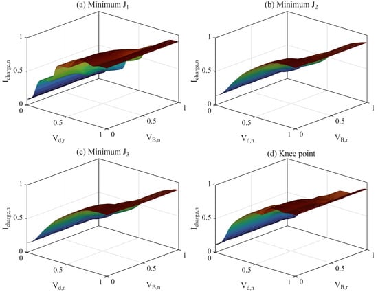
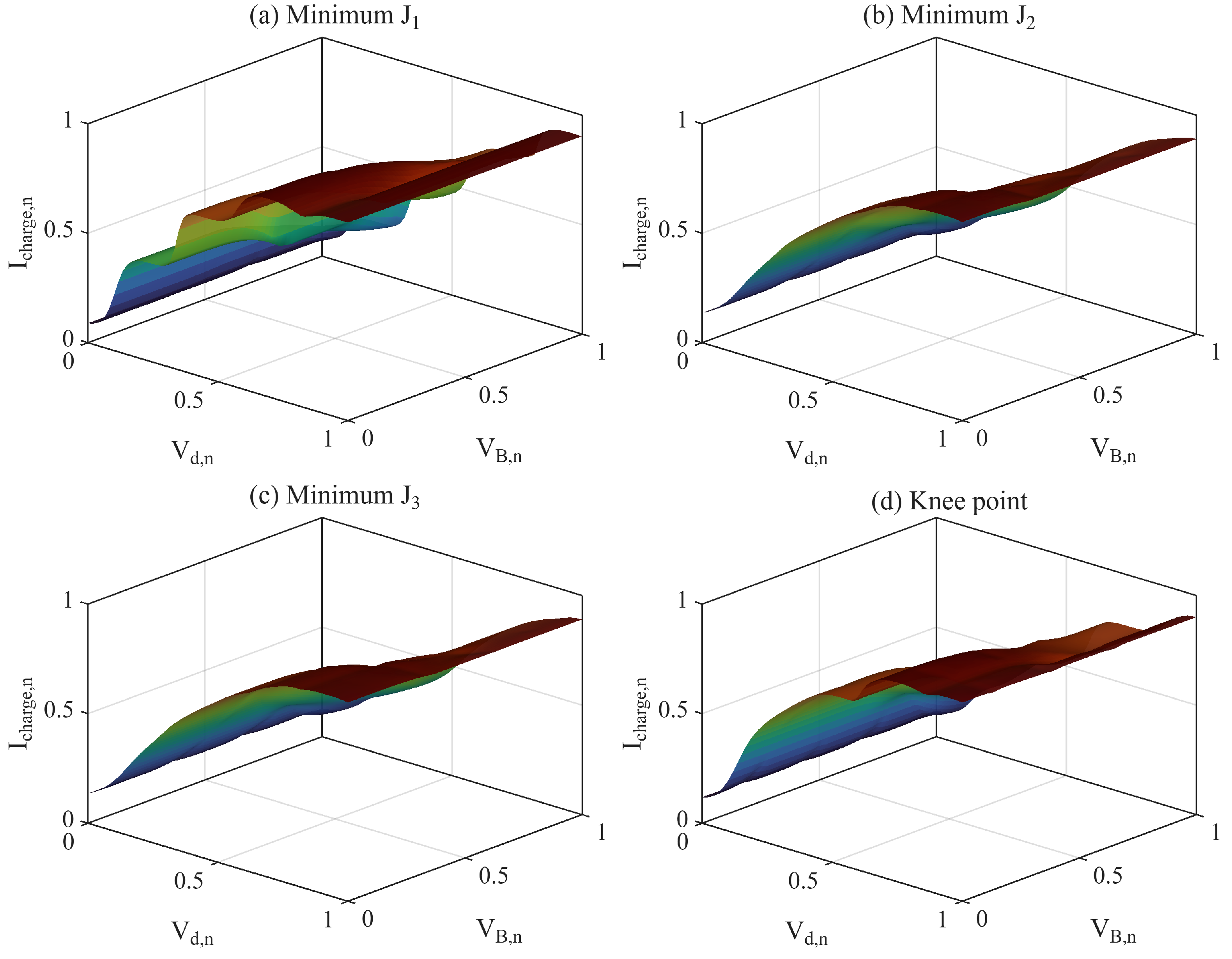
To further understand how the optimized fuzzy controllers achieve these trends, we show the fuzzy control surfaces of the four selected fuzzy controllers in Figure 7, where the normalized voltage-difference input and the normalized lowest-cell-voltage input are mapped to the normalized charging-current command . The minimum- controller, in contrast, has a more aggressive surface with higher normalized commands over a greater extent of the input space. This behavior explains its shorter charging time but also its higher temperature rise and current-stress index. The minimum- and minimum- controllers show smoother and more conservative surfaces, which reduce the commanded current and lead to lower thermal and current-stress objectives. The knee-point controller exhibits an intermediate surface shape, producing enough charging current to reduce charging time while avoiding the most aggressive behavior of the minimum- controller.
Figure 7.
Optimized fuzzy control surfaces for the selected Pareto-optimal controllers: (a) minimum-, (b) minimum-, (c) minimum-, and (d) knee-point solution. Each surface maps the normalized voltage difference and normalized lowest-cell voltage to the normalized charging-current command . The surface colors indicate the magnitude of the normalized charging-current command and are used only to improve visualization of the surface shape. The fastest controller produces a more aggressive current-command surface, while the minimum-temperature and minimum-current-stress controllers are more conservative. The knee-point controller provides an intermediate mapping.
Overall, the time-domain and control-surface results support the conclusions drawn from the Pareto front. The minimum- solution prioritizes charging speed by applying a larger charging current, but this increases the thermal and current-stress objectives. The minimum- and minimum- solutions reduce thermal and current-related stress by using more conservative charging commands but require longer charging times. The knee-point controller provides the most balanced time-domain behavior among the selected solutions and is therefore a suitable candidate for further analysis or implementation.
4.2. Robustness Analysis Under Initial-Condition and Cell-Parameter Variations
To evaluate whether the selected knee-point fuzzy charging controller remains effective beyond the nominal operating condition, a robustness analysis was performed under variations in initial SOC, cell-to-cell SOC imbalance, initial temperature, capacity scaling, and internal-resistance scaling. In this analysis, the fuzzy controller parameters were fixed at the knee-point solution obtained from the Pareto front, and no re-optimization was performed. Therefore, the robustness study evaluates the ability of the selected controller to maintain safe and effective charging performance under representative off-nominal battery conditions.
The robustness cases are summarized in Table 7. The capacity scale factor multiplies the nominal cell capacity, while the resistance scale factor multiplies the instantaneous resistance lookup table according to
Thus, represents reduced available capacity, while represents increased internal resistance, which may occur due to cell aging or parameter uncertainty. The tested cases include balanced low- and high-SOC initial conditions, cell-to-cell SOC imbalance, cool- and warm-start conditions, reduced capacity, increased resistance, and a combined worst-case condition.
Table 7.
Robustness test conditions for the knee-point fuzzy charging controller.
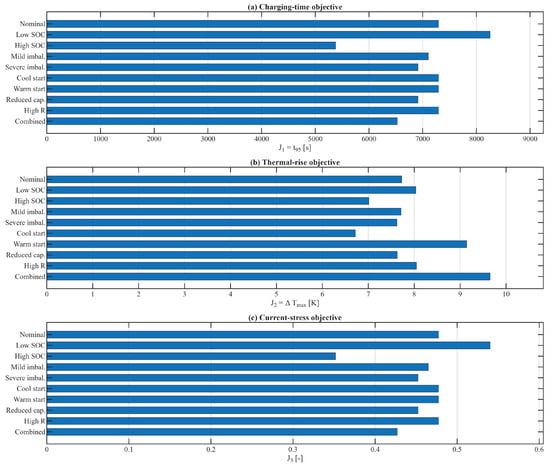
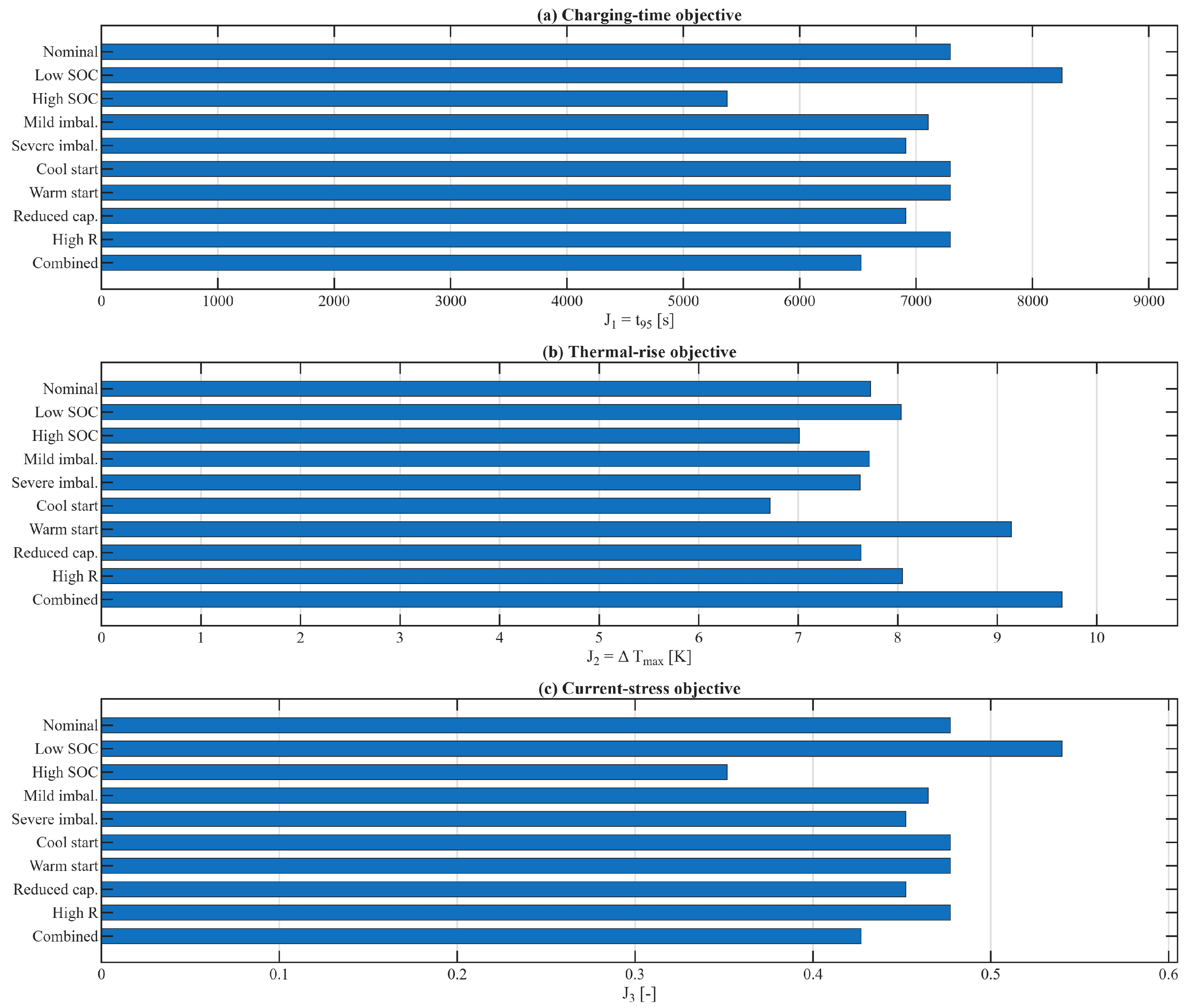
The effects of these robustness cases on the three objectives are shown in Figure 8. As expected, the low-SOC case has the largest charging-time objective, since the battery is further from the target SOC at the start. The high-SOC case has the lowest charge time and current-stress index, since it reaches the target charge with the least amount of charge flowing. The mild- and severe-imbalance cases are close to the nominal case, indicating that the controller is relatively insensitive to moderate initial differences in SOC between cells. The thermal-rise peak during operation is greater in the warm-start and combined cases. This is expected, since the warm-start case has a higher starting temperature, while the combined case has a lower capacity and increased resistance. However, the maximum temperature is below the imposed safety limit, indicating that the controller satisfies the imposed thermal safety constraint in simulation.
Figure 8.
Robustness performance of the knee-point fuzzy charging controller under the ten test cases: (a) charging-time objective , (b) thermal-rise objective , and (c) current-stress objective .
The observed robustness trends can be explained by the way in which capacity and resistance variations affect the feedback signals and the current-regulation logic. A reduced capacity, represented by , increases the SOC change produced by a given charging current. Therefore, for the same applied current, the battery reaches the target SOC sooner, and the safety-supervision logic sets the charging current to zero earlier. This explains why the reduced-capacity and combined cases do not necessarily produce the longest charging time, even though they represent degraded or off-nominal conditions.
In contrast, increased internal resistance, represented by , affects both the voltage response and the thermal response. A larger resistance increases ohmic polarization for the same charging current and also increases resistive heat generation. As a result, the cell voltages and pack voltage evolve differently, and the maximum temperature rise becomes larger. Since the fuzzy controller uses the voltage-difference signal and the lowest-cell-voltage signal , resistance-induced voltage changes can modify the controller input trajectory. In addition, the safety-supervision logic limits the applied current when the SOC or temperature constraints are reached. Thus, capacity decay mainly changes the SOC progression and cutoff time, while resistance growth mainly changes the voltage and thermal feedback that influence safe current regulation.
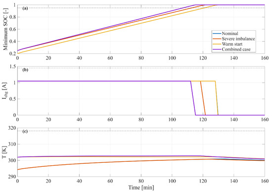
Some selected time-domain responses of the controller for the robustness cases are shown in Figure 9. The minimum SOC monotonically increases until the charge target is satisfied. The constant-current command is activated over most of the charging process, and a command of zero is generated when the charge target is satisfied. The combined case reaches the target faster than some selected cases because it starts with an imbalanced SOC distribution and reduced capacity. Despite the warmer initial condition and increased resistance, the temperature remains below the imposed thermal limit. This shows that, even though the initial conditions and parameter values differ from those of the nominal optimization case, the knee-point controller preserves the desired trade-off between fast charging and thermal safety.
Figure 9.
Representative time-domain responses of the knee-point fuzzy charging controller for selected robustness cases: (a) minimum SOC, (b) charging current, and (c) battery temperature. The dotted horizontal lines indicate the main operating limits used in the simulation, including the SOC limit, the maximum allowable charging current, and the temperature safety limit.
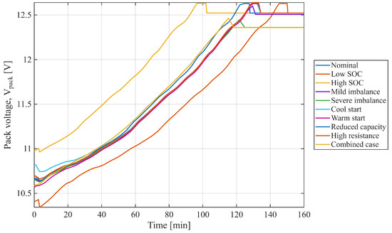
The pack voltage for each of the ten robustness cases is shown in Figure 10. The low-SOC case has the lowest initial pack voltage and the longest time to reach the upper region. The high-SOC case has a higher initial pack voltage and, as a result, the shortest time to reach the upper region. The nominal, imbalance, cool-start, warm-start, and reduced-capacity cases show similar growth trends in voltage, indicating that the controller gives similar pack-level behavior under moderate variations. In cases of higher resistance (high resistance and combined resistance), the voltage profiles are slightly different, as the scaled resistance will modify the voltage response for the same current command. Still, all of the voltage profiles remain bounded and approach the expected upper-voltage region, confirming the robustness of the chosen controller.
Figure 10.
Pack-voltage profiles for all robustness test cases.
Overall, the robustness results show that the knee-point fuzzy controller maintains acceptable charging performance under representative initial-condition and cell-parameter variations. The most demanding cases, including low SOC, warm start, high resistance, and the combined case, produce the largest changes in charging time, thermal rise, and current stress. Nevertheless, the controller reaches the target SOC while satisfying the thermal safety constraint.
5. Conclusions
This paper presents a current-stress-aware fuzzy logic control framework for safe fast charging of series-connected lithium-ion battery packs. The proposed controller uses the highest cell-voltage difference, , and the lowest single-cell voltage, , as physically meaningful feedback variables for regulating the charging-current command. Unlike conventional fuzzy charging approaches that rely on manually selected membership functions or weighted single-objective tuning, the proposed method formulates the controller design as a Pareto-based multi-objective optimization problem. The Gaussian membership-function parameters and the input/output scaling gains were optimized simultaneously using NSGA-II, resulting in a 21-variable controller design problem.
The optimization considered three competing objectives: minimizing the time required to reach 95% SOC, minimizing the maximum temperature rise, and minimizing a normalized current-stress index based on the integral of the squared charging current. This current-stress index is not a direct electrochemical aging model. It does not explicitly quantify lithium plating, SEI growth, capacity fade, or resistance growth. Instead, it is used as a simple current-severity indicator to reduce unnecessarily aggressive charging behavior when detailed aging-state information is not available. The resulting Pareto front confirmed the expected conflict among charging speed, thermal safety, and current-stress reduction. The fastest controller reached the target SOC in , but it produced the largest temperature rise and current-stress value among the selected solutions. In contrast, the minimum-temperature-rise and minimum-current-stress controllers used more conservative charging behavior and required longer charging times. The selected knee-point controller provided a balanced compromise, reaching the target SOC in while reducing the maximum temperature rise and the current-stress index relative to the fastest solution.
The time-domain analysis further confirmed the behavior observed in the Pareto front. The minimum- controller applied a more aggressive current profile and produced faster SOC and voltage responses, while the minimum- and minimum- controllers reduced the thermal and current-stress burden at the expense of longer charging duration. The knee-point controller showed intermediate current, temperature, SOC, and voltage responses, supporting its selection as the preferred controller. The optimized fuzzy control surfaces also showed how different Pareto-optimal solutions reshape the relationship between the normalized voltage-based inputs and the normalized charging-current command.
A robustness analysis was then performed using the fixed knee-point controller without re-optimization. The controller was evaluated under ten off-nominal conditions, including low and high initial SOC, cell-to-cell SOC imbalance, cool- and warm-start conditions, reduced capacity, increased internal resistance, and a combined worst-case scenario. The results showed that the knee-point controller maintained stable charging behavior, reached the target SOC, and satisfied the imposed thermal safety constraint under the tested perturbations. These results indicate that the proposed controller preserves good charging performance for representative worst-case variations in the initial conditions and the cell parameters beyond the nominal optimized case.
Overall, the proposed current-stress-aware Pareto-optimized fuzzy controller provides a systematic and interpretable framework for balancing fast charging, thermal protection, and battery stress. By including a normalized current-stress objective, the framework discourages unnecessarily aggressive current profiles and enables a more battery-conscious charging scheme than a charging-time-only control approach. The and the also allow the controller to account for cell imbalance and the lowest-voltage cell in the series string, which is important for pack-level charging safety.
Future work should extend the proposed framework in several directions: First, experimental validation should be performed using a hardware battery test bench or a hardware-in-the-loop platform to confirm the simulation-based results under real charging conditions, sensor noise, converter dynamics, sensor delay, dynamic polarization, cell-to-cell manufacturing variation, aging-related parameter changes, and thermal-environment variations. Such validation is needed before practical implementation, because these real-cell and hardware effects cannot be fully reproduced by simulation alone. Second, the method should be extended to larger series-parallel battery packs, where cell imbalance, thermal gradients, and pack-level constraints become more complex. In addition, scalability should be evaluated using larger series and series-parallel battery packs with stronger cell-to-cell imbalance, thermal gradients, and pack-level voltage and current constraints. Although the proposed inputs and provide compact indicators of voltage imbalance and weakest-cell conditions, larger packs may require additional feedback variables or hierarchical control structures. Third, detailed electrochemical aging models or data-driven degradation models should be incorporated so that the current-stress objective can be replaced or supplemented by direct aging-related objectives such as capacity fade, resistance growth, or lithium-plating risk. Long-term cycling experiments are also needed to determine how the proposed charging strategy affects capacity retention, resistance growth, and other practical aging indicators over repeated charge–discharge cycles. Fourth, a Type-II fuzzy logic controller could be investigated to better handle uncertainty in membership functions, battery parameters, measurements, and operating conditions. Since Type-II fuzzy systems can represent uncertainty in the fuzzy sets themselves, they may provide improved robustness compared with Type-I fuzzy control in applications where cell parameters and thermal conditions vary over time. Finally, future studies should consider robust multi-objective optimization, in which uncertainty in initial SOC, temperature, capacity, resistance, and model parameters is included during the optimization process rather than only evaluated after selecting a controller. Such an approach would allow the optimizer to search directly for controllers that are not only Pareto-optimal under nominal conditions, but also less sensitive to uncertainty from the early stages of the design process.
Author Contributions
Conceptualization, Y.S., A.S., and J.F.; methodology, Y.S. and J.F.; software, Y.S. and J.F.; validation, Y.S. and J.F.; formal analysis, Y.S. and J.F.; investigation, Y.S. and J.F.; resources, Y.S. and A.S.; data curation, Y.S. and J.F.; writing—original draft preparation, Y.S. and A.S.; writing—review and editing, Y.S. and A.S.; visualization, Y.S. and J.F.; supervision, Y.S. and A.S.; project administration, Y.S. and A.S. All authors have read and agreed to the published version of the manuscript.
Funding
This research received internal support from the Battery Research Institute at Marshall University and received no external funding.
Data Availability Statement
The raw data supporting the conclusions of this article will be made available by the authors upon reasonable request.
Acknowledgments
The authors gratefully acknowledge the Battery Research Institute–Marshall University for partially funding this research. The authors used an AI-based language tool to improve the grammar, clarity, and readability of the manuscript. The tool was not used to generate scientific content, analyses, results, or conclusions. The authors have reviewed and edited the output and take full responsibility for the content of this publication.
Conflicts of Interest
The authors declare no conflicts of interest.
Abbreviations
The following abbreviations and symbols are used in this manuscript:
| CC | Constant current |
| CC–CV | Constant current/constant voltage |
| CV | Constant voltage |
| FIS | Fuzzy inference system |
| FLC | Fuzzy logic controller |
| Li-ion | Lithium-ion |
| MF | Membership function |
| MOP | Multi-objective optimization problem |
| NSGA-II | Non-Dominated Sorting Genetic Algorithm II |
| PCA | Principal component analysis |
| SOC | State-of-charge |
| Charging-time objective | |
| Maximum temperature-rise objective | |
| Normalized current-stress objective | |
| Cell-voltage difference | |
| Lowest single-cell voltage | |
| VS | Very small |
| S | Small |
| M | Medium |
| L | Large |
| VL | Very large |
References
- Tomaszewska, A.; Chu, Z.; Feng, X.; O’Kane, S.; Liu, X.; Chen, J.; Ji, C.; Endler, E.; Li, R.; Liu, L.; et al. Lithium-Ion Battery Fast Charging: A Review. eTransportation 2019, 1, 100011. [Google Scholar] [CrossRef] [Scilit]
- Rahman, T.; Alharbi, T. Exploring Lithium-Ion Battery Degradation: A Concise Review of Critical Factors, Impacts, Data-Driven Degradation Estimation Techniques, and Sustainable Directions for Energy Storage Systems. Batteries 2024, 10, 220. [Google Scholar] [CrossRef] [Scilit]
- Edge, J.S.; O’Kane, S.; Prosser, R.; Kirkaldy, N.D.; Patel, A.N.; Hales, A.; Ghosh, A.; Ai, W.; Chen, J.; Yang, J.; et al. Lithium Ion Battery Degradation: What You Need to Know. Phys. Chem. Chem. Phys. 2021, 23, 8200–8221. [Google Scholar] [CrossRef] [Scilit]
- Gao, Z.; Xie, H.; Yang, X.; Niu, W.; Li, S.; Chen, S. The Dilemma of C-Rate and Cycle Life for Lithium-Ion Batteries under Low Temperature Fast Charging. Batteries 2022, 8, 234. [Google Scholar] [CrossRef] [Scilit]
- Bernardi, D.; Pawlikowski, E.; Newman, J. A General Energy Balance for Battery Systems. J. Electrochem. Soc. 1985, 132, 5–12. [Google Scholar] [CrossRef] [Scilit]
- Keil, P.; Jossen, A. Charging Protocols for Lithium-Ion Batteries and Their Impact on Cycle Life—An Experimental Study with Different 18650 High-Power Cells. J. Energy Storage 2016, 6, 125–141. [Google Scholar] [CrossRef] [Scilit]
- Vermeer, W.; Stecca, M.; Chandra Mouli, G.R.; Bauer, P. A Critical Review on The Effects of Pulse Charging of Li-ion Batteries. In Proceedings of the 2021 IEEE 19th International Power Electronics and Motion Control Conference (PEMC); IEEE: Piscataway, NJ, USA, 2021; pp. 217–224. [Google Scholar] [CrossRef] [Scilit]
- Tahir, M.U.; Sangwongwanich, A.; Stroe, D.I.; Blaabjerg, F. Overview of Multi-Stage Charging Strategies for Li-ion Batteries. J. Energy Chem. 2023, 84, 228–241. [Google Scholar] [CrossRef] [Scilit]
- Chen, G.; Liu, Z.; Su, H. An Optimal Fast-Charging Strategy for Lithium-Ion Batteries via an Electrochemical–Thermal Model with Intercalation-Induced Stresses and Film Growth. Energies 2020, 13, 2388. [Google Scholar] [CrossRef] [Scilit]
- Yin, Y.; Choe, S.Y. Actively Temperature Controlled Health-Aware Fast Charging Method for Lithium-Ion Battery Using Nonlinear Model Predictive Control. Appl. Energy 2020, 271, 115232. [Google Scholar] [CrossRef] [Scilit]
- Tian, N.; Fang, H.; Wang, Y. Real-Time Optimal Lithium-Ion Battery Charging Based on Explicit Model Predictive Control. IEEE Trans. Ind. Inform. 2020, 17, 1318–1330. [Google Scholar] [CrossRef] [Scilit]
- Wang, X.; Jiang, B. Multi-Objective Optimization for Fast Charging Design of Lithium-Ion Batteries Using Constrained Bayesian Optimization. J. Power Sources 2023, 584, 233602. [Google Scholar] [CrossRef] [Scilit]
- Park, S.; Pozzi, A.; Whitmeyer, M.; Perez, H.; Kandel, A.; Kim, G.; Choi, Y.; Joe, W.T.; Raimondo, D.M.; Moura, S. A Deep Reinforcement Learning Framework for Fast Charging of Li-Ion Batteries. IEEE Trans. Transp. Electrif. 2022, 8, 2770–2784. [Google Scholar] [CrossRef] [Scilit]
- Liu, C.L.; Chiu, Y.S.; Liu, Y.H.; Ho, Y.H.; Huang, S.S. Optimization of a Fuzzy-Logic-Control-Based Five-Stage Battery Charger Using a Fuzzy-Based Taguchi Method. Energies 2013, 6, 3528–3547. [Google Scholar] [CrossRef] [Scilit]
- Ali, M.U.; Nengroo, S.H.; Khan, M.A.; Zeb, K.; Kamran, M.A.; Kim, H.J. A Real-Time Simulink Interfaced Fast-Charging Methodology of Lithium-Ion Batteries under Temperature Feedback with Fuzzy Logic Control. Energies 2018, 11, 1122. [Google Scholar] [CrossRef] [Scilit]
- Károlyi, G.; Pózna, A.I.; Hangos, K.M.; Magyar, A. An Optimized Fuzzy Controlled Charging System for Lithium-Ion Batteries Using a Genetic Algorithm. Energies 2022, 15, 481. [Google Scholar] [CrossRef] [Scilit]
- Khan, N.; Ooi, C.A.; Alturki, A.; Amir, M.; Alharbi, T. A Critical Review of Battery Cell Balancing Techniques, Optimal Design, Converter Topologies and Performance Evaluation for Optimizing Storage System in Electric Vehicles. Energy Rep. 2024, 11, 4999–5032. [Google Scholar] [CrossRef] [Scilit]
- Panasonic/Sanyo. NCR18650PF Lithium-Ion Cell Data Sheet. Panasonic/Sanyo, 2016. Official Cell Specification Sheet Listing CC–CV Charging, 4.20 V Charge Voltage, Standard Charging Current, Typical Capacity, Charge-Temperature Range, and Reduced-Rate Charging Below 10 Degrees C. Available online: https://www.eistoelectronics.com/web/userfiles/download/Panasonic/NCR18650PF.pdf (accessed on 20 August 2026).
- MathWorks. Unit Delay: Delay Signal One Sample Period. 2026. MATLAB/Simulink documentation. Available online: https://www.mathworks.com/help/simulink/slref/unitdelay.html (accessed on 21 August 2026).
- MathWorks. Remove Algebraic Loops. 2026. MATLAB/Simulink Documentation. Available online: https://www.mathworks.com/help/simulink/ug/remove-algebraic-loops.html (accessed on 21 August 2026).
- Sardahi, Y.; Boker, A. Multi-objective optimal design of four-parameter PID controls. In Dynamic Systems and Control Conference; American Society of Mechanical Engineers: Atlanta, GA, USA, 2018; Volume 51890, p. V001T01A001. [Google Scholar]
- Kalita, K.; Ramesh, J.V.N.; Čep, R.; Jangir, P.; Pandya, S.B.; Ghadai, R.K.; Abualigah, L. Many-Objective Whale Optimization Algorithm for Engineering Design and Large-Scale Many-Objective Optimization Problems. Int. J. Comput. Intell. Syst. 2024, 17, 171. [Google Scholar] [CrossRef] [Scilit]
- Pandya, S.B.; Kalita, K.; Jangir, P.; Ghadai, R.K.; Abualigah, L. Multi-objective Geometric Mean Optimizer (MOGMO): A Novel Metaphor-Free Population-Based Math-Inspired Multi-objective Algorithm. Int. J. Comput. Intell. Syst. 2024, 17, 91. [Google Scholar] [CrossRef] [Scilit]
- Ravichandran, S.; Manoharan, P.; Sinha, D.K.; Jangir, P.; Abualigah, L.; Alghamdi, T.A. Multi-Objective Resistance-Capacitance Optimization Algorithm: An Effective Multi-Objective Algorithm for Engineering Design Problems. Heliyon 2024, 10, e35921. [Google Scholar] [CrossRef] [Scilit]
- Pareto, V.; Schwier, A.S. Manual of Political Economy Tr. by Ann S. Schwier; Macmillan: London, UK, 1927. [Google Scholar]
- Deb, K.; Pratap, A.; Agarwal, S.; Meyarivan, T. A fast and elitist multiobjective genetic algorithm: NSGA-II. IEEE Trans. Evol. Comput. 2002, 6, 182–197. [Google Scholar] [CrossRef] [Scilit]
- Zitzler, E.; Laumanns, M.; Thiele, L. SPEA2: Improving the strength Pare—to evolutionary algorithm. Evol. Comput. 2001, 5, 121. [Google Scholar]
- Emmerich, M.; Deutz, A.H. A tutorial on multiobjective optimization: Fundamentals and evolutionary methods. Nat. Comput. 2018, 17, 585–609. [Google Scholar] [CrossRef] [Scilit]
- Zhang, Q.; Li, H. MOEA/D: A Multiobjective Evolutionary Algorithm Based on Decomposition. IEEE Trans. Evol. Comput. 2007, 11, 712–731. [Google Scholar] [CrossRef] [Scilit]
- Hernández, C.; Naranjani, Y.; Sardahi, Y.; Liang, W.; Schütze, O.; Sun, J.Q. Simple cell mapping method for multi-objective optimal feedback control design. Int. J. Dyn. Control 2013, 1, 231–238. [Google Scholar] [CrossRef] [Scilit]
- Tamiz, M.; Jones, D.; Romero, C. Goal programming for decision making: An overview of the current state-of-the-art. Eur. J. Oper. Res. 1998, 111, 569–581. [Google Scholar] [CrossRef] [Scilit]
- Marler, R.T.; Arora, J.S. Survey of multi-objective optimization methods for engineering. Struct. Multidiscip. Optim. 2004, 26, 369–395. [Google Scholar] [CrossRef] [Scilit]
- Tian, Y.; Cheng, R.; Zhang, X.; Jin, Y. PlatEMO: A MATLAB platform for evolutionary multi-objective optimization [educational forum]. IEEE Comput. Intell. Mag. 2017, 12, 73–87. [Google Scholar] [CrossRef] [Scilit]
- Zheng, W.; Doerr, B. Mathematical Runtime Analysis for the Non-Dominated Sorting Genetic Algorithm II. Artif. Intell. 2023, 325, 104016. [Google Scholar] [CrossRef] [Scilit]
- Ishibuchi, H.; Sakane, Y.; Tsukamoto, N.; Nojima, Y. Evolutionary many-objective optimization by NSGA-II and MOEA/D with large populations. In Proceedings of the 2009 IEEE International Conference on Systems, Man and Cybernetics; IEEE: Piscataway, NJ, USA, 2009; pp. 1758–1763. [Google Scholar]
- Durillo, J.J.; Nebro, A.J.; Coello, C.A.C.; García-Nieto, J.; Luna, F.; Alba, E. A study of multiobjective metaheuristics when solving parameter scalable problems. IEEE Trans. Evol. Comput. 2010, 14, 618–635. [Google Scholar] [CrossRef] [Scilit]
- MathWorks. gamultiobj: Find Pareto Front of Multiple Fitness Functions Using Genetic Algorithm. 2026. MATLAB Global Optimization Toolbox documentation. Available online: https://www.mathworks.com/help/gads/gamultiobj.html (accessed on 21 August 2026).
- MathWorks. PlatEMO: Evolutionary Multi-Objective Optimization Platform. 2026. MATLAB Central File Exchange. Available online: https://www.mathworks.com/matlabcentral/fileexchange/105260-platemo (accessed on 21 August 2026).
- Blank, J.; Deb, K. pymoo: Multi-Objective Optimization in Python. IEEE Access 2020, 8, 89497–89509. [Google Scholar] [CrossRef] [Scilit]
- Pymoo Developers. NSGA-II: Non-Dominated Sorting Genetic Algorithm. 2026. pymoo Documentation. Available online: https://pymoo.org/algorithms/moo/nsga2.html (accessed on 21 August 2026).

Disclaimer/Publisher’s Note: The statements, opinions and data contained in all publications are solely those of the individual author(s) and contributor(s) and not of MDPI and/or the editor(s). MDPI and/or the editor(s) disclaim responsibility for any injury to people or property resulting from any ideas, methods, instructions or products referred to in the content. |
© 2026 by the authors. Licensee MDPI, Basel, Switzerland. This article is an open access article distributed under the terms and conditions of the Creative Commons Attribution (CC BY) license.