1. Introduction
Loss-of-excitation faults are a common fault type of pumped storage units, which means that the excitation of a pumped storage unit is completely or partially lost, so loss-of-excitation faults can be classified as faults with complete or partial loss of excitation. The main causes of complete loss of excitation are rotor winding faults, exciter faults, false tripping of the de-excitation switch, etc. The main reasons for partial losses of excitation are faults of automatic voltage regulators and slight short circuits of rotor windings [
1,
2,
3].
When the loss of excitation fault occurs, on the one hand, because the generator needs to absorb a large amount of reactive power from the power grid to establish a magnetic field, the grid voltage may decrease and, in severe cases, voltage collapse may occur; on the other hand, due to the existence of asynchronous torque, a fault will cause vibration of the unit, which directly threatens the unit’s safe and stable operation [
4,
5]. Therefore, reliable and rapid detection of losses of excitation is essential for ensuring unit safety and secure grid operation.
At present, loss-of-excitation protection based on the impedance principle is the most widely used. According to the measured impedance trajectory of the generator terminal after the loss of excitation, an operating region is defined. If the measured impedance trajectory remains within the operating region within the setting delay, the loss of excitation fault is determined. There are two kinds of loss-of-field impedance protection criteria [
6]: (1) the criterion of loss-of-excitation impedance for asynchronous boundary setting; (2) loss-of-excitation impedance criterion of static stability boundary setting.
The advantage of loss-of-excitation protection based on the impedance principle is that the principle is simple and easy to understand and implement. However, it also has some shortcomings: (1) The protection method based on the impedance principle poses a risk of maloperation and cannot effectively distinguish a loss of excitation and the stable power oscillation of the system [
7], resulting in maloperation of protection function under system oscillation. (2) Based on the impedance-based protection method, there is a risk of poor speed or failure to operate. Taking the loss-of-excitation impedance criterion set according to the static stability boundary as an example, the modified static stability boundary impedance circle is generally used as the operating region in China. The modified static stability boundary resistance circle has a large deviation from the theoretical static stability boundary near the horizontal axis, which makes the relay act slightly later when the generator is demagnetized under heavy load conditions, and the larger the system contact reactance X
S is, the more significant the effect is, and the poorer the protection speed is [
6]. In addition, when the pumped storage unit has a partial loss-of-excitation fault, the power angle
δ increases more slowly than when a complete loss-of-excitation fault occurs. The speed of the measured impedance trajectory at the generator terminals to the operating region becomes slower, and it may even sway at the action boundary, causing the timer to be reset repeatedly, thereby prolonging the operating time, and the protection has poor operating speed for partial loss-of-excitation faults [
8]. At the same time, the light load condition aggravates and deteriorates its operating speed performance, and even causes the protection to fail to operate.
Numerous studies have investigated improvements to loss-of-excitation protection. Due to the natural correlation between the admittance plane and the power plane of a pumped storage unit, the loss-of-excitation operating region set on the admittance plane in the literature [
9,
10] can intuitively show the cooperation between the loss-of-excitation protection and the low excitation limit, which has certain advantages in engineering. However, the loss-of-excitation protection based on the impedance principle also has its shortcomings [
11]. In addition to the protection method based on the principle of impedance and admittance, other loss-of-excitation protection methods can be roughly divided into two categories. One is to extract indicators from the electrical quantities of the generator to distinguish loss of excitation and other faults. Reference [
12] is based on the reactive power increment strategy. When the terminal voltage is less than the threshold, the strategy is triggered, and the terminal voltage is detected again to distinguish the loss-of-excitation and non-loss-of-excitation events, but the anti-maloperation performance of the system oscillation is not described. Reference [
13] constructed the loss-of-excitation protection by detecting the change trend of the power angle of the parallel pumped storage unit connected to the connection point. However, when the system disturbance and the loss-of-excitation fault occur simultaneously, the change trend of the power angle may change, and the protection performance is poor. Reference [
14] judged whether the loss-of-excitation fault occurred by detecting the change rate of the resistance component of the measured impedance of the unit. Reference [
15] distinguished the loss of excitation event by the internal voltage of the pumped storage unit. Another method of loss-of-excitation protection is based on artificial intelligence, which mainly uses fuzzy logic [
16], decision tree [
17], artificial neural network [
18] and other algorithms. However, the above methods usually require a large amount of training data, and their protection performance depends on the power system and generator conditions and training data, but the mobility is poor [
19].
Therefore, this paper proposes a new method of pumped storage unit loss-of-excitation fault protection based on the variation characteristics of electrical quantities. Firstly, the variation trend of each electrical quantity of the generator during the loss of excitation and system oscillation is analyzed and compared, and the difference is found. Then, the criterion of loss-of-excitation index based on the magnitude and polarity of the variation of V, Q and δ of the pumped storage unit is proposed, where V, Q and δ represent the RMS value of the terminal voltage, the output reactive power of the generator and the power angle of the generator, respectively. The innovation of this paper is that this method is not a simple superposition of multiple electrical quantities or a separate threshold, but is based on the synergistic change mechanism of terminal voltage drop, reactive power output decrease and power angle increase caused by the continuous attenuation of excitation potential in the process of loss-of-excitation. The polarity consistency product index of ΔV, ΔQ and Δδ is constructed. Finally, in order to evaluate the performance of the new method, simulations and verification under multiple working conditions are carried out. The results show that the loss-of-excitation protection method based on the variation characteristics of electrical quantities has good reliability and rapidity.
2. Electrical Characteristics During Loss-of-Excitation and System Oscillation
After the loss of excitation of a pumped storage unit, the excitation current attenuates. Since the no-load electromotive force E0 of the pumped storage unit is proportional to the excitation current, the E0 is reduced. Therefore, the output electromagnetic power of the pumped storage unit is reduced, and the corresponding braking electromagnetic torque is reduced, which is less than the driving mechanical torque input by the prime mover, resulting in the acceleration of the rotor and the increase in the power angle δ of the pumped storage unit.
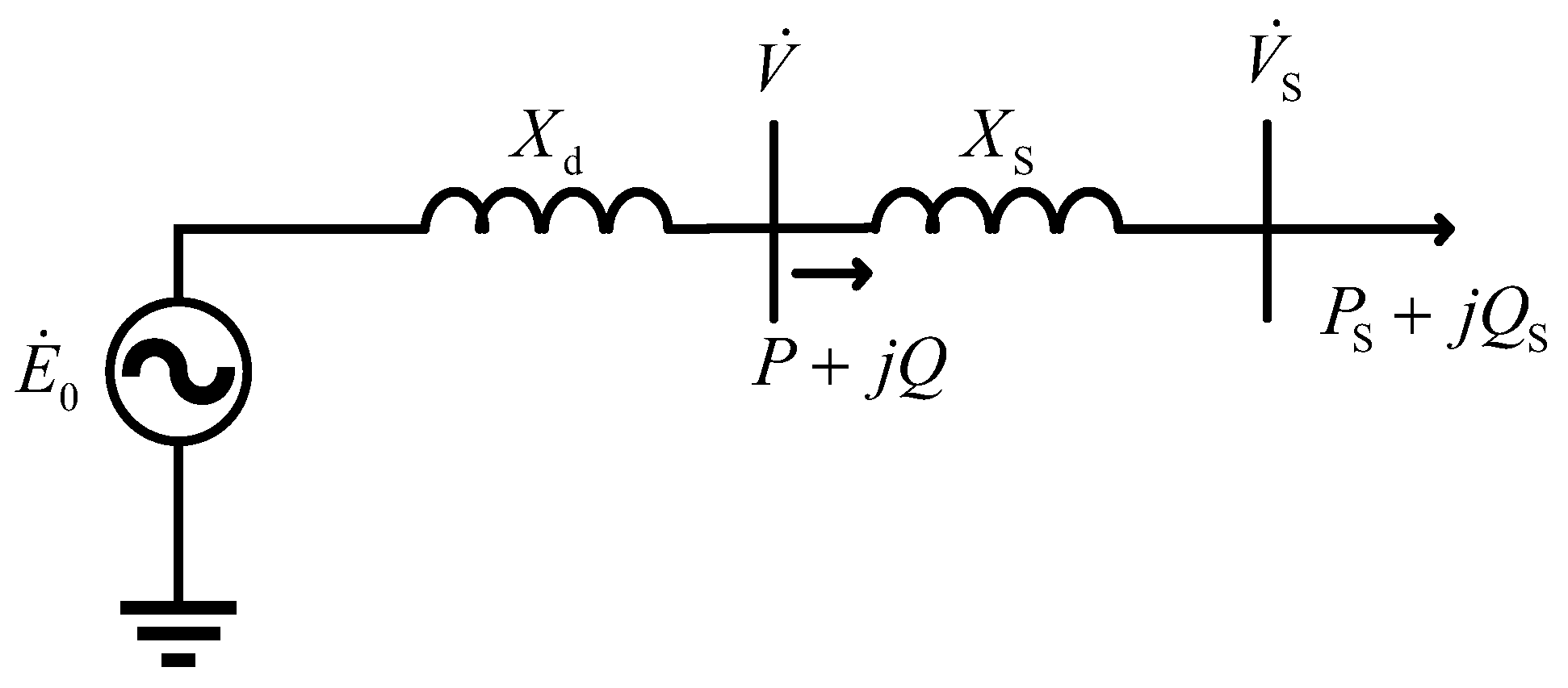
Taking the parallel operation of a pumped storage unit and infinite bus system shown in
Figure 1 as an example, the model assumes that the three-phase symmetry of the system, the infinite bus voltage and the external equivalent reactance remain unchanged within the protection discrimination time window, ignoring the stator resistance, and the synchronous reactance of the pumped storage unit takes a fixed value near the rated operating point. The nonlinear magnetic circuit effects such as magnetic saturation, cross saturation, hysteresis and eddy current are ignored. It can be obtained that
In the formula, Ps and Qs are the active power and reactive power of the generator output to the system, respectively; Vs is the grid-side voltage; Xd is synchronous reactance of the generator; Xs is the contact reactance between the generator and the infinite system; δ is the power angle.
For the active power
Ps, the power angle
δ increases and sin
δ increases, but
E0 decreases. Because the increase in sin
δ and the decrease in
E0 compensate each other, the active power
Ps is basically unchanged. For reactive power
Qs, the derivative of Formula (2) is
In the initial stage of loss-of-excitation, the pumped storage unit satisfies: . Consequently, the derivative of the reactive power Qs is less than zero, and the reactive power decreases rapidly, which will change from positive to negative, that is, the unit transitions from supplying reactive power to absorbing reactive power from the grid. In the power system, the flow direction of inductive reactive power is from high voltage to low voltage, so the reduction and reverse of inductive reactive power represent the drop in terminal voltage. After the loss of excitation, the excitation source of the generator to establish the magnetic field is mainly the grid side, so the terminal current contains a large reactive power component, and the terminal current increases.
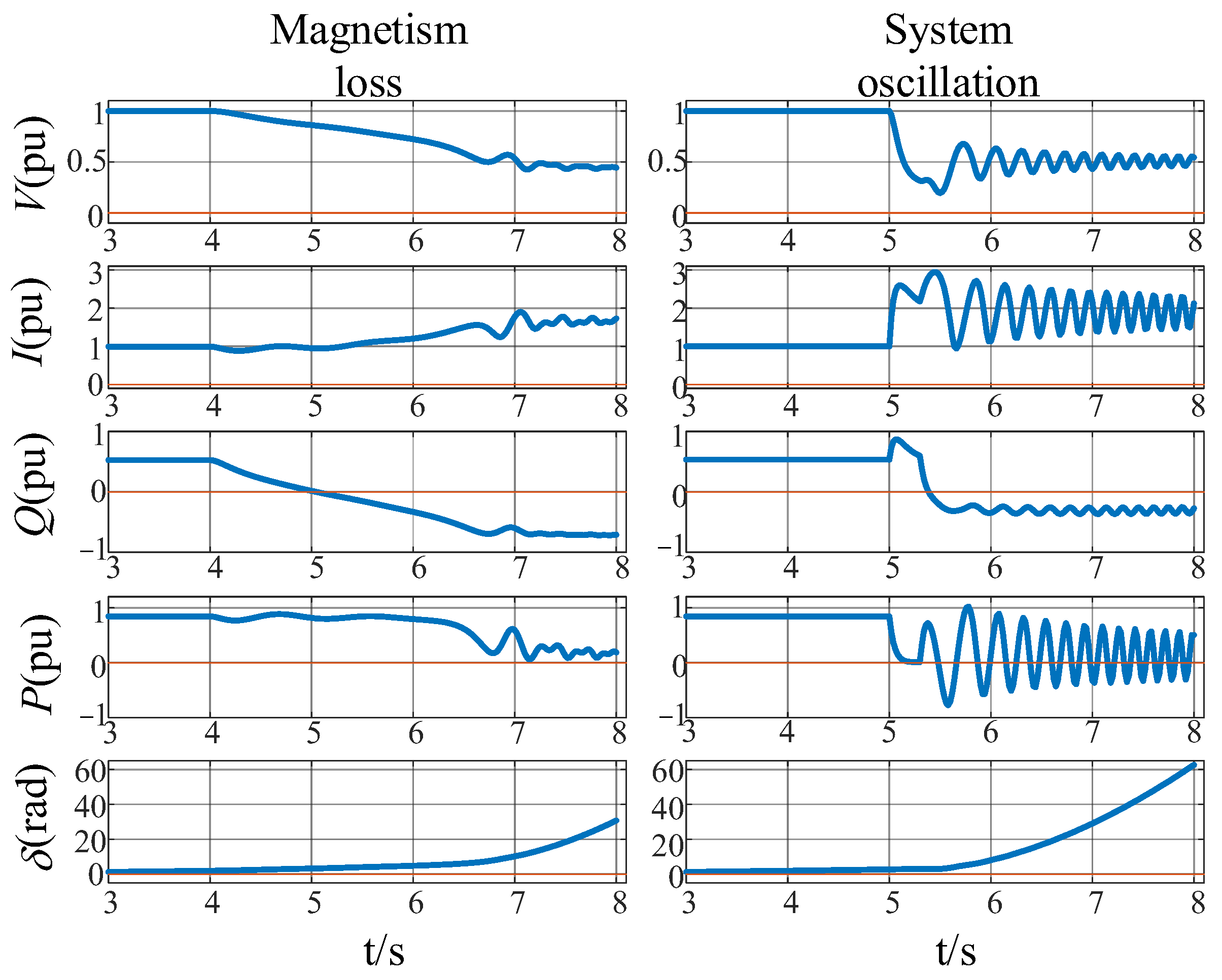
In summary, after the loss of excitation of the pumped storage unit, the power angle δ increases, the output active power is basically unchanged, the output inductive reactive power decreases until the reverse, the terminal voltage decreases, and the terminal current increases. After the generator is demagnetized, if no measures are taken, the pumped storage unit will eventually lose synchronization. Therefore, before the unit loses synchronism, the change trend of the electrical quantity conforms to the above change rule.
When the system oscillates, the power angle
δ changes periodically in the range of –180°~180°, so that the voltage, line current and the magnitude and direction of power flow of each point in the system also show periodic changes. Using the simulation model built in the
Section 3, the simulation results for the electrical quantities of the pumped storage unit during the loss of excitation and system oscillation are shown in
Figure 2.
In addition, the terminal voltage, current, active power and reactive power of the pumped storage unit are easy to measure. However, the power angle δ cannot be directly measured. The following introduces a method to obtain the power angle δ based on the rotor motion equation of the generator.
Generator rotor motion equation:
In the formula, ‘*‘ is the per-unit value, which is the inertia time constant of the pumped storage unit; T1 and TM are mechanical input torque and electromagnetic torque, respectively. ω0 is the synchronous electrical angular velocity.
Combining Equations (4) and (5) yields
Integrating both sides of Equation (6) with respect to time yields
Equation (7) can therefore be rewritten as
By multiplying
dt on both sides of Equation (8), we get
By discretizing (9), we obtain
Regarding the choice of the size of Δt when solving the power angle, for the accuracy of the solution, of course, the smaller the Δt, the higher the accuracy of the solution, but the smaller the Δt, the higher the computing power requirements of the computer. Based on the above, when calculating the power angle, this paper selects Δt as 200 us.
For the solution of
δ0, for the non-salient pole motor:
In the formula, P, Q and V are the active power, reactive power and voltage of the normal operation before the loss of excitation.
3. Pumped Storage Unit Loss-of-Excitation Protection Based on Electrical Variation
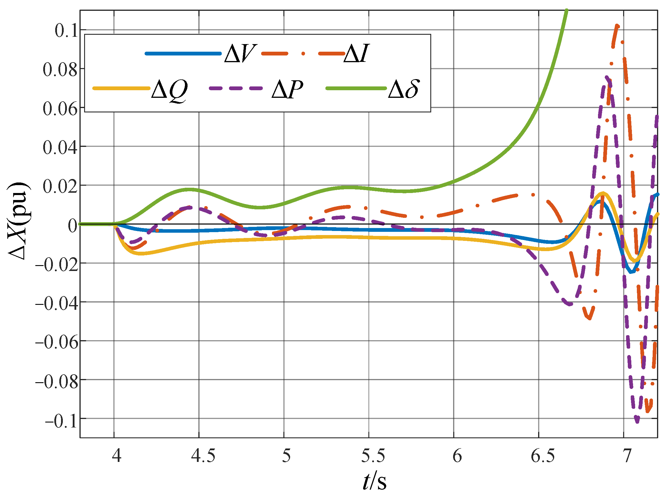
During the loss-of-excitation process, some electrical quantities show monotonic variation characteristics; during the system oscillation, all electrical quantities show continuous oscillation. This difference provides a basis for judging the loss-of-excitation fault. Consider that a criterion based on a single electrical quantity may be susceptible to maloperation, exhibiting limited reliability. Therefore, it is highly feasible in theory to comprehensively utilize the variation characteristics of multiple electrical quantities and jointly construct the loss-of-excitation protection criterion.
The variation of each electrical quantity is introduced:
Among them,
X is the electrical quantity, and
XB is the base value of each electrical quantity. For the power angle variation Δ
δ, 1 rad is used to standardize per unit, and ∆
t is 20 ms in this paper. Using the simulation model built in
Section 3, the simulation results of the variation of each electrical quantity during the loss of excitation are shown in
Figure 3.
Define the loss-of-excitation index
SC:
Among them,
X is the electrical quantity, and
KG is the gain coefficient to improve the clarity of the loss-of-excitation index. The size of
KG is related to the number of variables n. In this paper, when n = 2 and 3,
KG is 10
6 and 10
8, respectively. Using the simulation model built in the
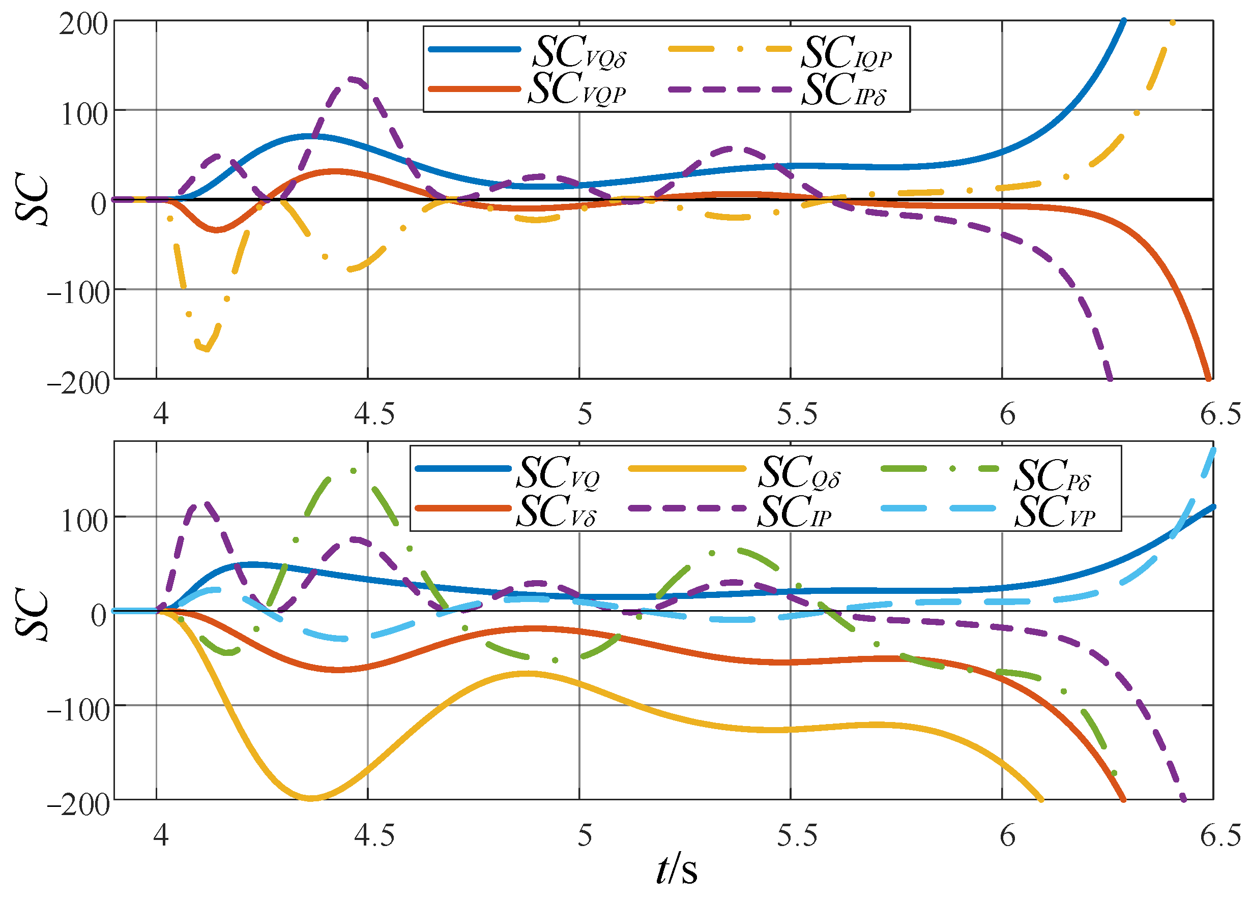
Section 3, the loss-of-excitation index of the pumped storage unit during the loss of excitation is shown in
Figure 4.
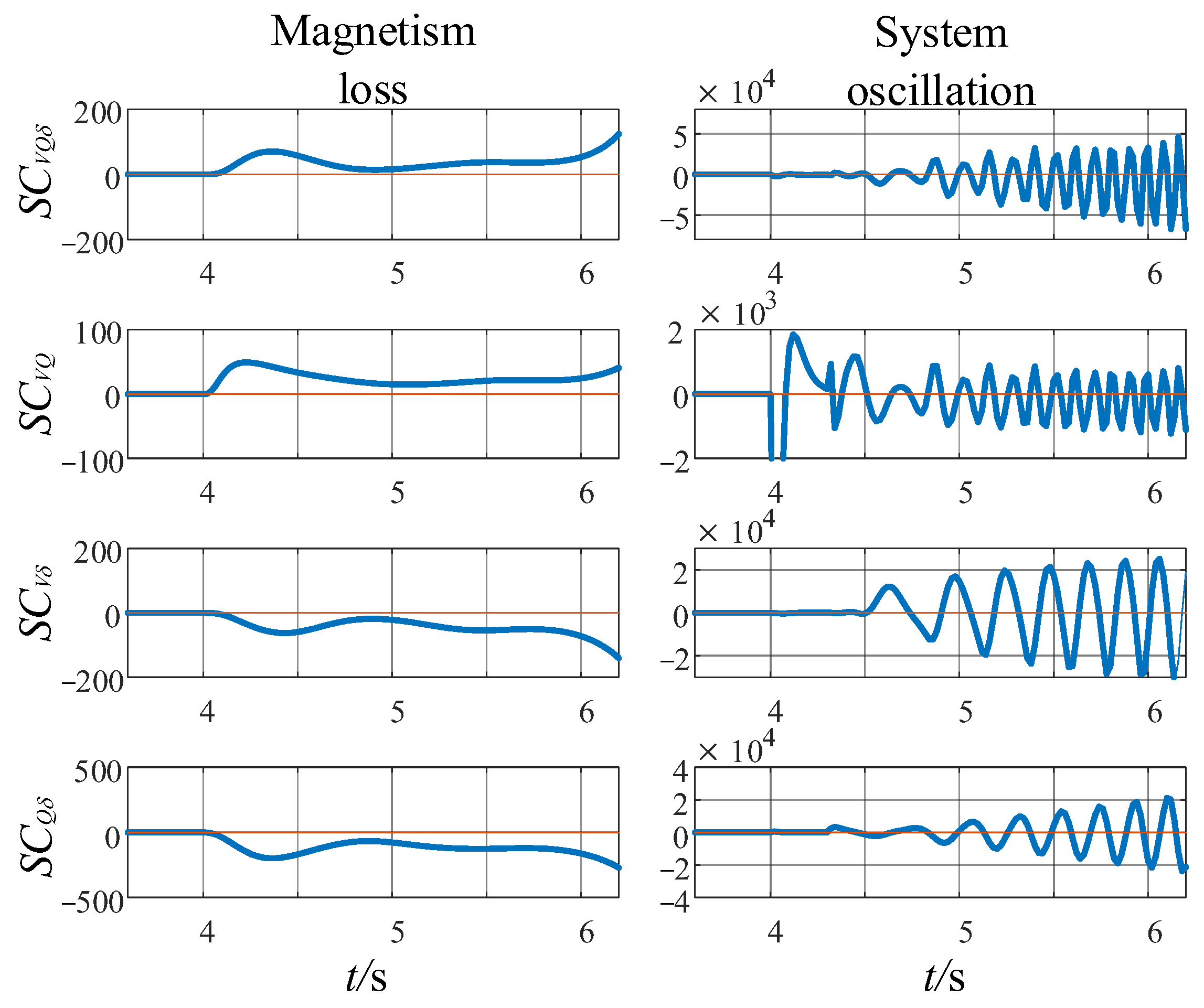
The simulation results for the loss-of-excitation index show that under the loss-of-excitation and system oscillation scenarios, each index shows different polarity characteristics: during the loss-of-excitation period, some loss-of-excitation indexes maintain unipolarity, while during the oscillation period, all loss-of-excitation indexes inevitably show bipolar changes. This difference provides a key basis for effectively distinguishing loss-of-excitation and system oscillation. Therefore, it is reasonable to choose the loss-of-excitation index with constant polarity during the loss-of-excitation period to constitute the loss-of-excitation protection criterion.
Therefore,
,
,
and
are selected as the loss-of-excitation criteria, and the response characteristics of the selected loss-of-excitation index under system oscillation are compared, as shown in
Figure 5. The simulation results show that the performance of the selected index is obviously different during the loss-of-excitation and oscillation, which confirms the rationality of the selected index as the loss-of-excitation criterion. Considering that the more electrical quantities are combined to construct the loss-of-excitation protection, the higher the protection reliability is, this paper finally selects
to construct the loss-of-excitation criterion.
The loss-of-excitation index
is always positive during the loss-of-excitation period, and the loss-of-excitation criterion is
In view of the fact that the loss-of-excitation index will also be greater than zero during the system oscillation, in order to prevent protection maloperation, a time-delay element is introduced into the criterion. The setting of the delay time Tset needs to be based on 1/2 of the maximum period Tmax of the loss-of-excitation index oscillation.
The periodic changes of all electrical quantities directly follow the periodic changes of the power angle. Therefore, the oscillation period of each electrical quantity is completely consistent with the oscillation period of the power angle. If the oscillation period of δ is T, ideally, the loss-of-excitation index during the oscillation of the system is obtained by multiplying the sine quantities with three periods of T and arbitrary initial phase angle. Using the triangular identity transformation, it can be seen that the product function is simplified, and the oscillation period is still T.
Therefore, the maximum period
Tmax of the oscillation period of
is the maximum period of the power angle oscillation, which is the reciprocal of the lowest frequency
fmin of the system oscillation.
The specific value of
fmin is determined by the parameters of pumped storage unit and power system, the size of transmission power and other factors [
20,
21,
22], which can be obtained by engineering experience or simulation. Therefore, the setting value of the delay time
Tset is
Among them, krel is the reliability coefficient of the delay setting, and 1.1 is taken in this paper.
Through simulation, it is found that when the system is in normal operation, the loss-of-excitation index is also greater than zero and lasts for a long time. In order to reliably prevent maloperation of the protection when the system is in normal operation, the criterion threshold in the criterion (15) is changed to obtain the final criterion of the loss-of-excitation index.
In the formula, is the maximum value of the loss-of-excitation index during the normal operation of the system. The value of different units may be different, and it must be obtained by the normal operation data of the protected unit. Krel is the reliability coefficient and is set to 100. In the simulation experiment in this paper, the size of is about . Therefore, the magnitude of the criterion threshold of the loss-of-excitation index is 10−2, and the magnitude of the loss-of-excitation index during the loss-of-excitation period is 101, which is much larger than the criterion threshold.
The constructed loss-of-excitation index does not represent an independent electromagnetic physical quantity, but is used to describe the synergy of voltage support, reactive power exchange and electromechanical dynamic response under loss-of-excitation fault. After the loss of excitation occurs, the excitation potential continues to decay, resulting in a decrease in the terminal voltage, a decrease in the reactive power output, and a continuous increase in the power angle. The larger the index value is, the more significant and synchronous the three loss-of-excitation characteristics of terminal voltage drop, reactive power output drop and rotor acceleration in the current observation window are.
In view of the fact that the loss-of-excitation fault is a symmetrical fault, considering that the proposed protection method may have the risk of maloperation when an asymmetric fault occurs in the system, a negative-sequence voltage blocking element is introduced. Only when the negative sequence voltage is less than the set value threshold is the protection enabled. The specific setting is as follows:
In the formula, V2 is the negative-sequence voltage at the generator terminals, V2.set is the negative-sequence voltage setting value, and VN is the rated phase voltage of the generator.
Since each electrical quantity is sampled discretely with Δ
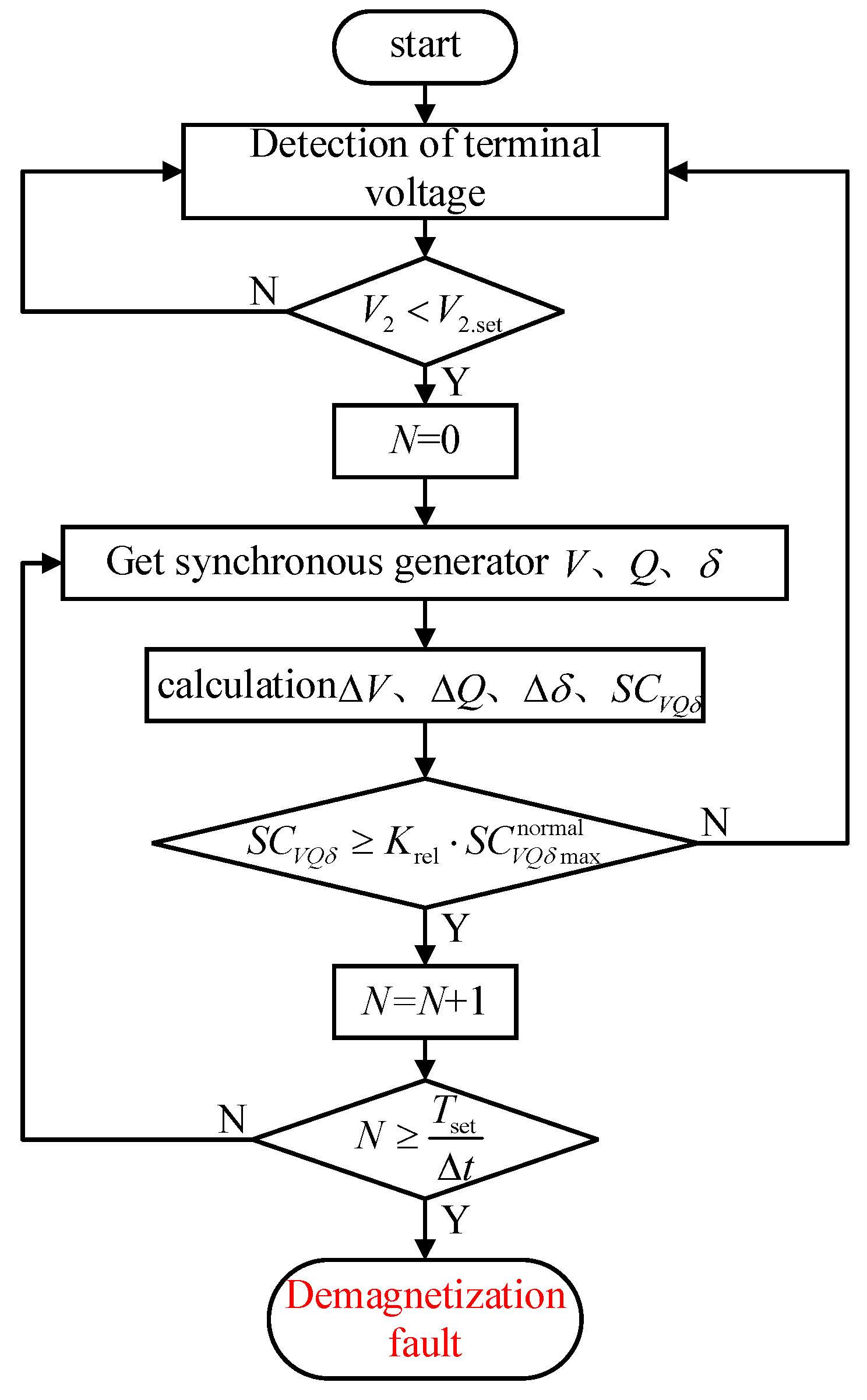
t as the sampling period, the protection operation is equivalent to continuous
Tset/Δ
t loss-of-excitation indexes satisfying the loss-of-excitation criterion.
Figure 6 shows the flow chart of the proposed protection method.
4. Simulation Verification
In order to fully verify the performance of the proposed protection method, the simulation contents of this chapter include the following: the response characteristics of the loss-of-excitation index of the pumped storage unit when the loss-of-excitation fault occurs under different working conditions; the anti-maloperation performance of the protection during the system oscillation; the anti-maloperation performance of the protection during the internal or external asymmetric fault of the generator; the influence of the negative-sequence voltage-blocking element on the reliability of the protection; the influence of the electrical measurement noise and the communication delay on the performance of the proposed protection method; and a comparative analysis of the proposed method and the impedance-based loss-of-excitation protection in terms of operating speed, reliability, and implementation complexity. The applicability of the proposed protection method under different rated capacity and time constants is analyzed. In this section, the delay time Tset of the protection method is set to 1.5 s.
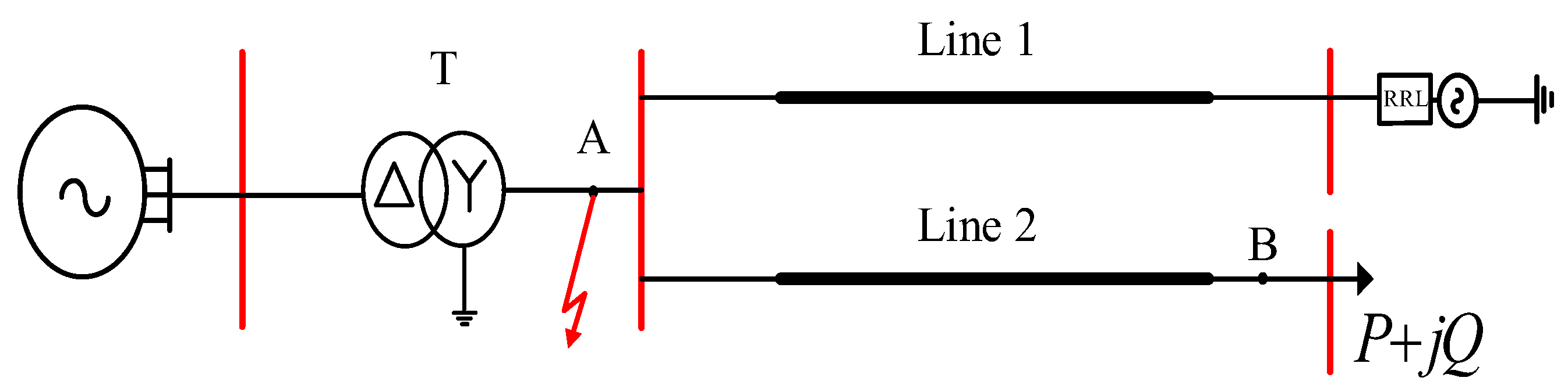
The simulation circuit is built by PSCAD/EMTDC. The specific simulation circuit is shown in
Figure 7, and the relevant parameters are shown in
Table 1.
4.1. Response Characteristics of Loss-of-Excitation Index Under Different Working Conditions
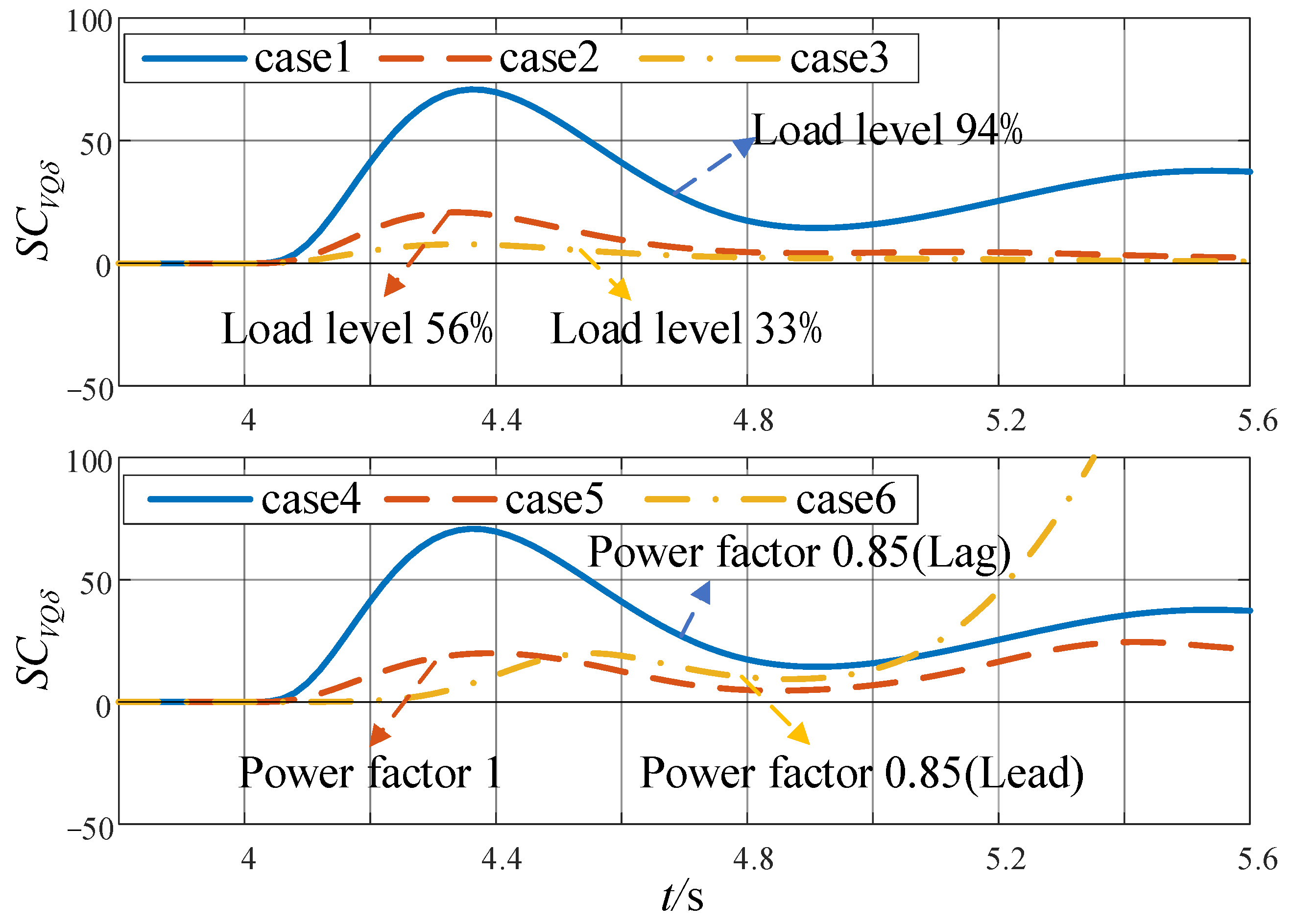
The loss-of-excitation index of the pumped storage unit shows the ideal response characteristics under the rated working conditions, but whether the response characteristics of the loss-of-excitation index are still ideal under the actual operating conditions of the pumped storage unit is worthy of further exploration. This paper focuses on the analysis of the influence of active load level and power factor on the discrimination performance of protection. The data of each simulation case are shown in
Table 2, and the simulation results are shown in
Figure 8.
The simulation results show that the variation trend of the loss-of-excitation index under different operating conditions is consistent with that under rated conditions, and the difference lies in the amplitude. Under the condition of constant power factor, the higher the active load level, the greater the amplitude of the loss-of-excitation index; under the condition of constant active load, the more inductive reactive power the pumped storage unit emits during normal operation, the greater the amplitude of the loss-of-excitation index. Since the threshold (order of magnitude: 10−2) is much smaller than the loss-of-excitation index (order of magnitude: 101), the proposed protection method can stably meet the loss-of-excitation index criterion, so different working conditions have almost no effect on the discrimination performance of the protection.
4.2. The Anti-Maloperation Performance of the Proposed Protection Method for System Oscillation
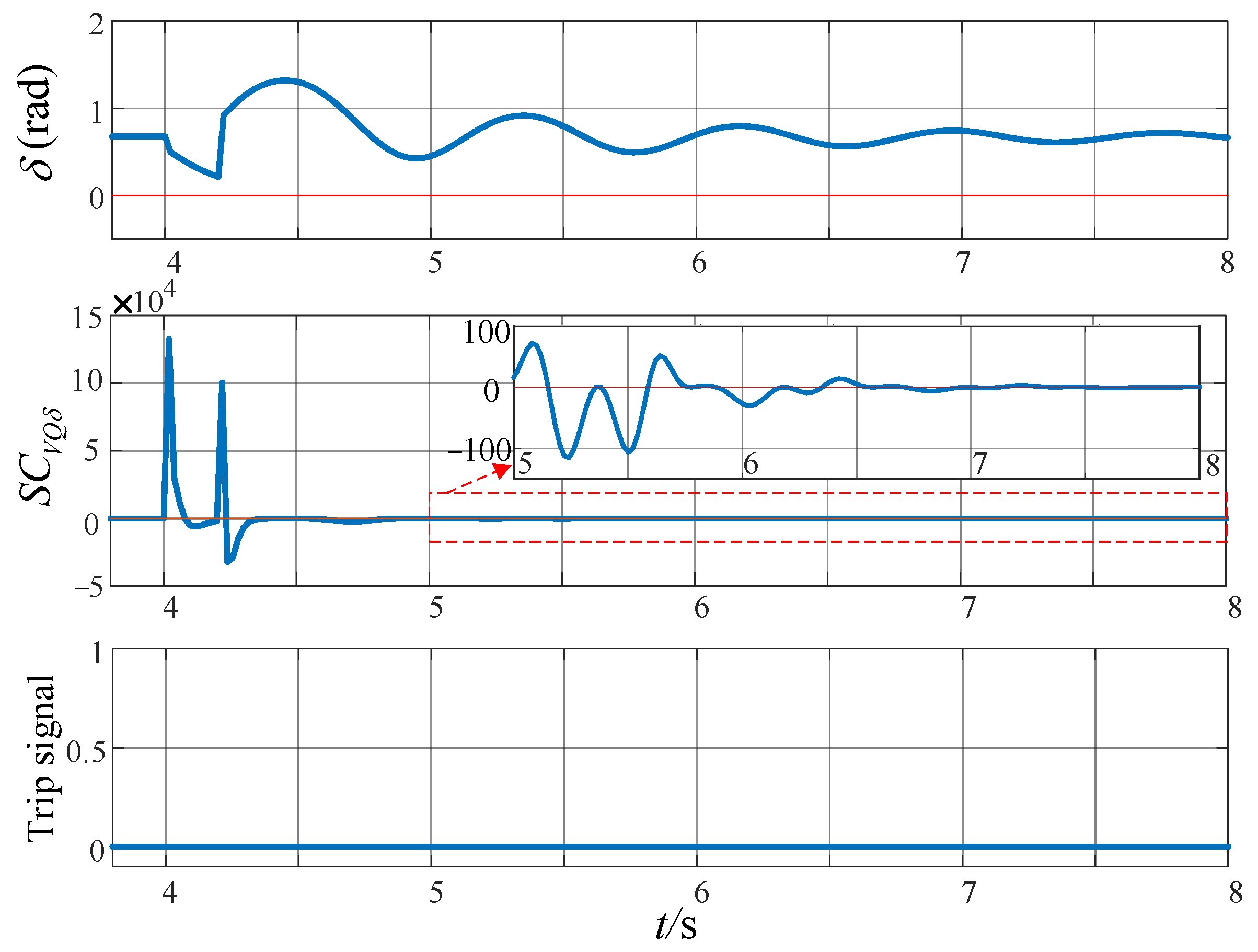
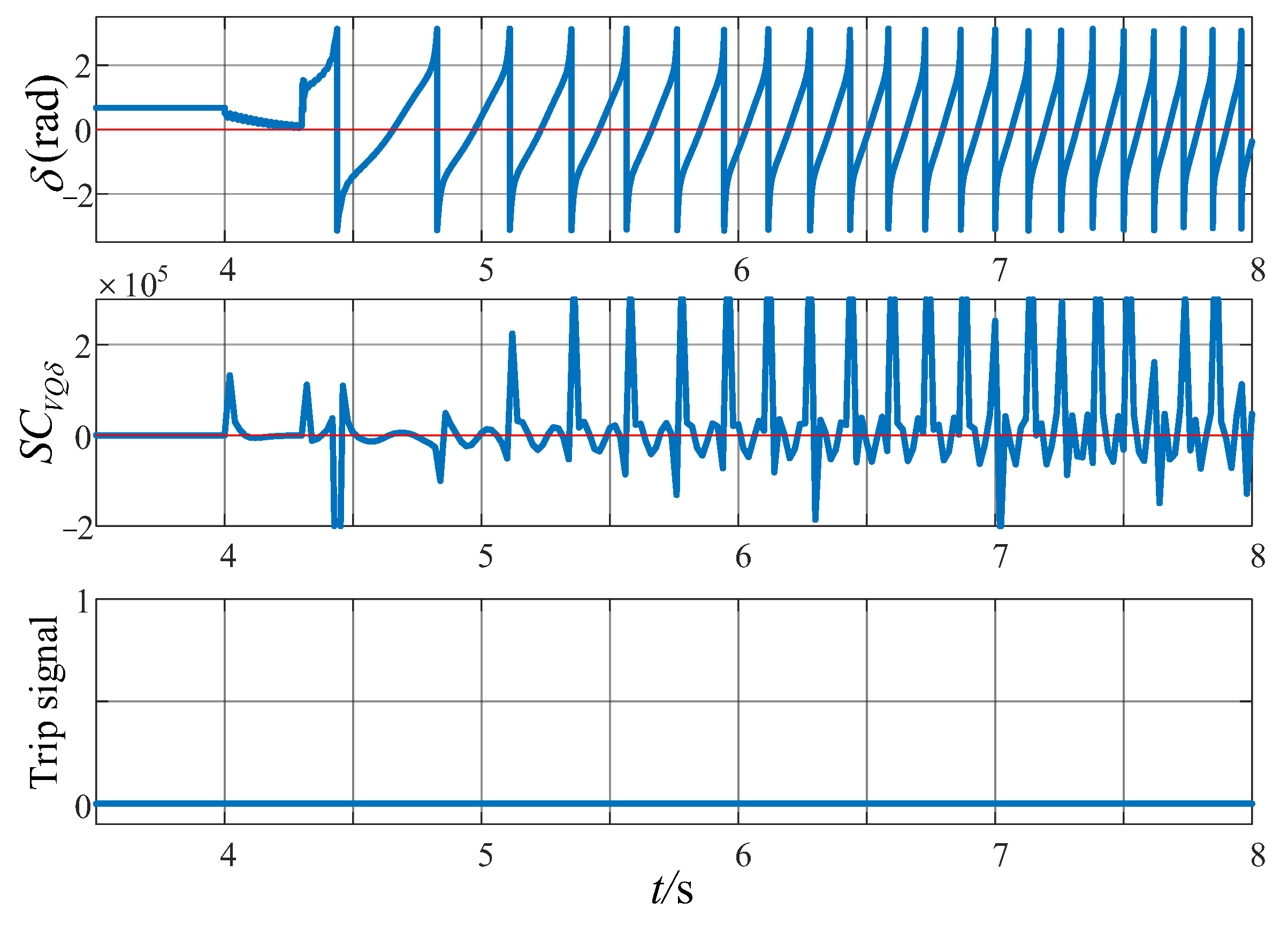
The performance of the loss-of-excitation index in low-frequency and high-frequency system oscillations is simulated. When
t = 4 s, a three-phase short circuit is applied at point A in
Figure 7, and the fault duration is set to 0.2 s and 0.3 s, respectively, to simulate low-frequency and high-frequency system oscillations. The simulation results are shown in
Figure 9 and
Figure 10.
The simulation results show that there is no maloperation of the protection during the low-frequency or high-frequency system oscillation. The loss-of-excitation protection based on the variation characteristics of electrical quantities has good anti-maloperation performance for system oscillations.
4.3. The Anti-Maloperation Performance of the Proposed Protection Method for Asymmetric Faults
In order to fully verify the anti-maloperation performance of the proposed protection method, in addition to system oscillations, its performance under internal and external asymmetric faults of the generator is also crucial.
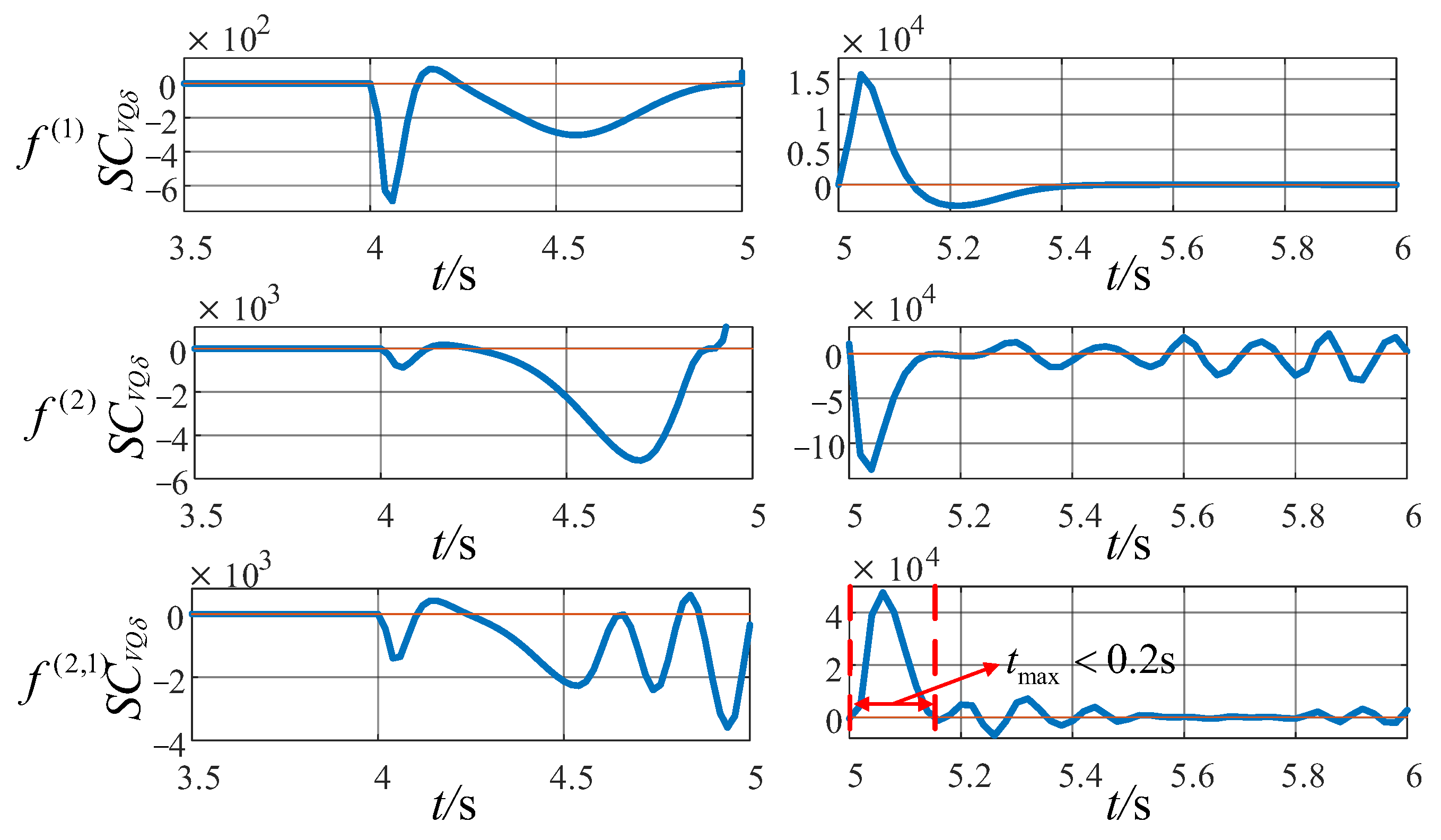
When point A
t = 4 s in
Figure 7, three typical external asymmetric fault scenarios of single-phase grounding (fault duration 1 s), two-phase phase-to-phase (fault duration 1 s), and two-phase short-circuit grounding (fault duration 1 s) are set to observe the response characteristics of the loss-of-excitation index under various types of asymmetric faults. Due to the large difference in the magnitude of the loss-of-excitation index before and after the fault removal, in order to fully display the simulation results, it is divided into two columns with
t = 5 s as the boundary. The final simulation results are shown in
Figure 11.
The simulation results show that when various types of asymmetric faults occur outside the machine, the loss-of-excitation index presents positive and negative bipolar fluctuations, which is quite different from the performance characteristics of the loss-of-excitation index when the loss-of-excitation fault occurs, and the maximum positive polarity duration tmax is within 0.2 s, which is less than the delay time Tset = 1.5 s of the proposed protection method, and the protection setting relying only on Tset will not malfunction. When the negative sequence blocking is added, the protection is reliably blocked during the fault period, double measures are taken to prevent the protection from maloperation, and the protection reliability is higher.
In case 1 and case 2 of
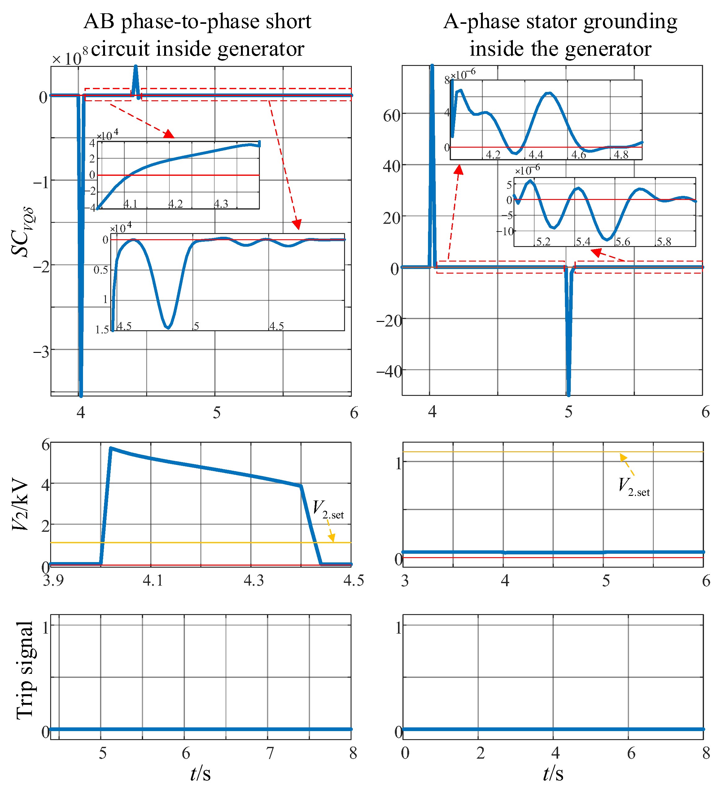
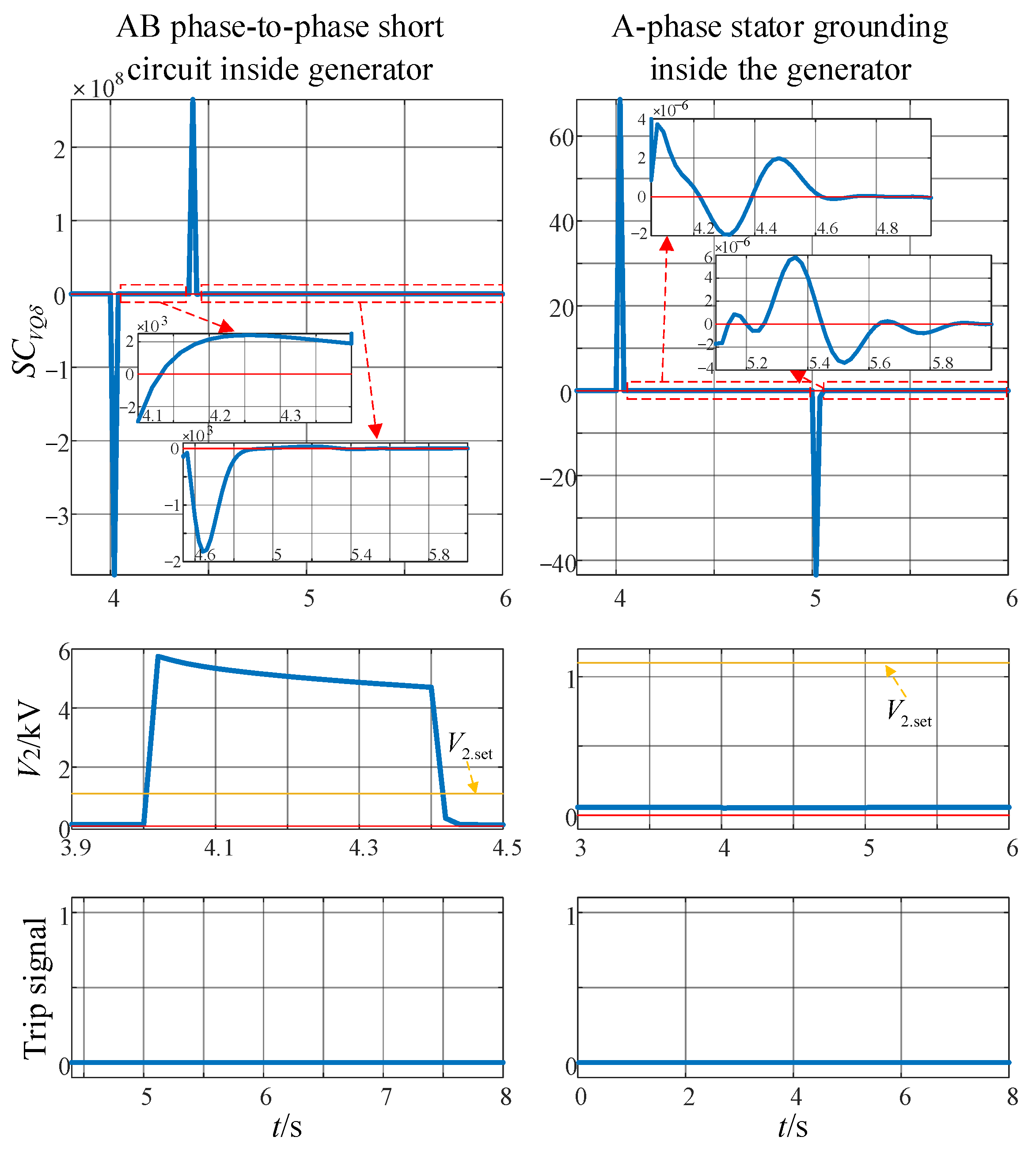
Table 2, the ab-phase-to-phase short-circuit fault (fault duration 0.4 s) and the a-phase stator ground fault (fault duration 1 s) are applied to the generator, and the anti-maloperation performance of the proposed protection method is simulated and verified. The simulation results are shown in
Figure 12 and
Figure 13.
The simulation results show that when the phase-to-phase short circuit occurs inside the generator, the protection method proposed in this paper can effectively block during the fault, and the loss-of-excitation index cannot continue to meet the loss-of-excitation index criterion in the delay time Tset after the fault is removed. The protection does not malfunction, and the protection has good anti-maloperation performance for the phase-to-phase short-circuit fault in the generator. For the stator ground fault in the machine, although the negative-sequence voltage is small during the fault, the protection cannot be blocked, but the time when the loss-of-excitation index shows positive and negative bipolar fluctuations and continues to be positive is less than the protection setting delay Tset, and the protection will not malfunction.
In summary, for the asymmetric faults inside and outside the generator, the protection method proposed in this paper can maintain reliable operation without maloperation, showing its good anti-interference ability and robustness.
4.4. Influence of Negative-Sequence Voltage Blocking Element on Protection Reliability
The reliability analysis of the proposed protection method can be divided into the following four cases: (1) asymmetric and non-loss-of-excitation faults occur inside or outside the generator, and the protection is required not to malfunction; (2) the system oscillates and requires protection not to malfunction; (3) a loss-of-excitation fault occurs, and the protection is required to prevent maloperation; (4) a loss-of-excitation fault occurs with an external asymmetric fault at the same time, and the protection is required to prevent maloperation. The following classification discusses the influence of negative-sequence voltage blocking on the protection reliability of the proposed protection method in each case.
(1) Case 1: In view of the risk of maloperation of the loss-of-excitation index criterion under asymmetric faults, a negative-sequence voltage blocking element is added to the protection, which forms a double anti-maloperation guarantee with the setting delay. The protection is only open when the negative-sequence voltage is lower than the threshold, which significantly improves the protection reliability of the proposed protection method under asymmetric faults.
(2) Case 2 and case 3: The system oscillation and loss-of-excitation fault are symmetrical events, the negative-sequence voltage at the generator terminals is small, and the negative-sequence voltage blocking element is not activated. In such cases, the protection relies on the delay time Tset to prevent maloperation during oscillation. After the loss of excitation, the protection stability meets the criterion of the loss-of-excitation index to ensure the reliable operation of the protection. Therefore, in this case, the negative-sequence voltage blocking element does not affect the protection reliability of the proposed protection method.
(3) Case 4: In view of the potential failure of the negative-sequence voltage blocking element in the proposed method to operate when the loss-of-excitation and external asymmetric faults are concurrent, the following analysis is carried out in this paper:
First of all, from the perspective of the independence of fault types, the generator loss-of-excitation fault and the external asymmetric fault belong to different physical mechanisms. There is no direct causal relationship or induction mechanism between the two, and they are independent, random events. A single fault itself is a small-probability event, and the probability of both occurring at the same time is smaller. For such a minimal probability of concurrent events, the principle of separately configuring special protection is usually adopted in engineering.
Secondly, from the perspective of the coordination of the protection operation sequence, the external line voltage level of the large pumped storage unit is higher, and the longitudinal differential protection is configured. When an asymmetric fault occurs on the line, the line longitudinal differential protection can remove the fault in a very short time (about 20 ms), which is much smaller than the setting delay of the protection method proposed in this paper. Therefore, even if the loss-of-excitation fault and external fault occur at the same time, the negative-sequence voltage is greater than the threshold blocking protection, and the external fault will be removed first by the line longitudinal differential protection. After the fault is removed, the negative-sequence voltage is less than the threshold value, and the proposed protection is re-enabled, which can still reliably detect the loss-of-excitation fault.
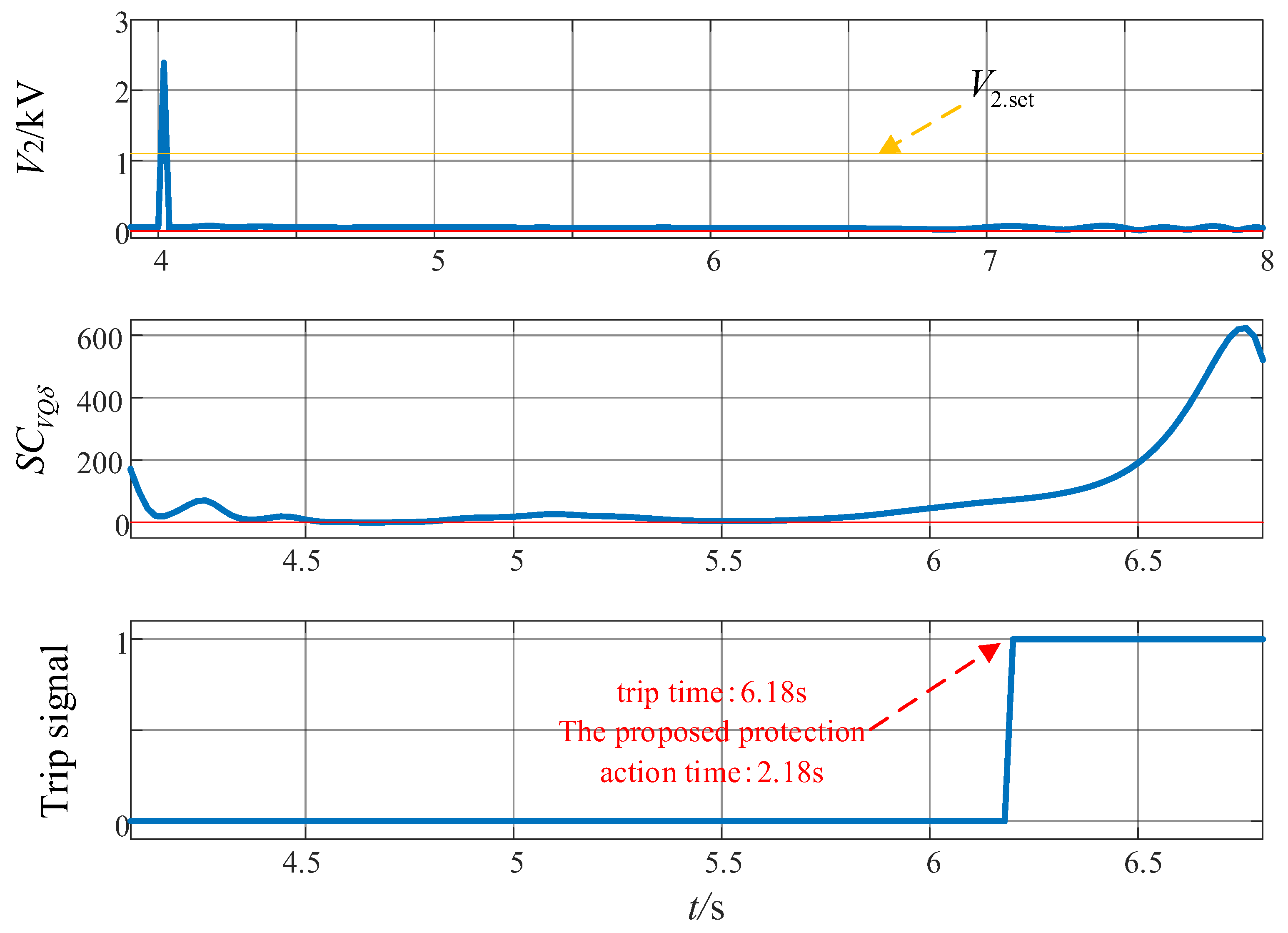
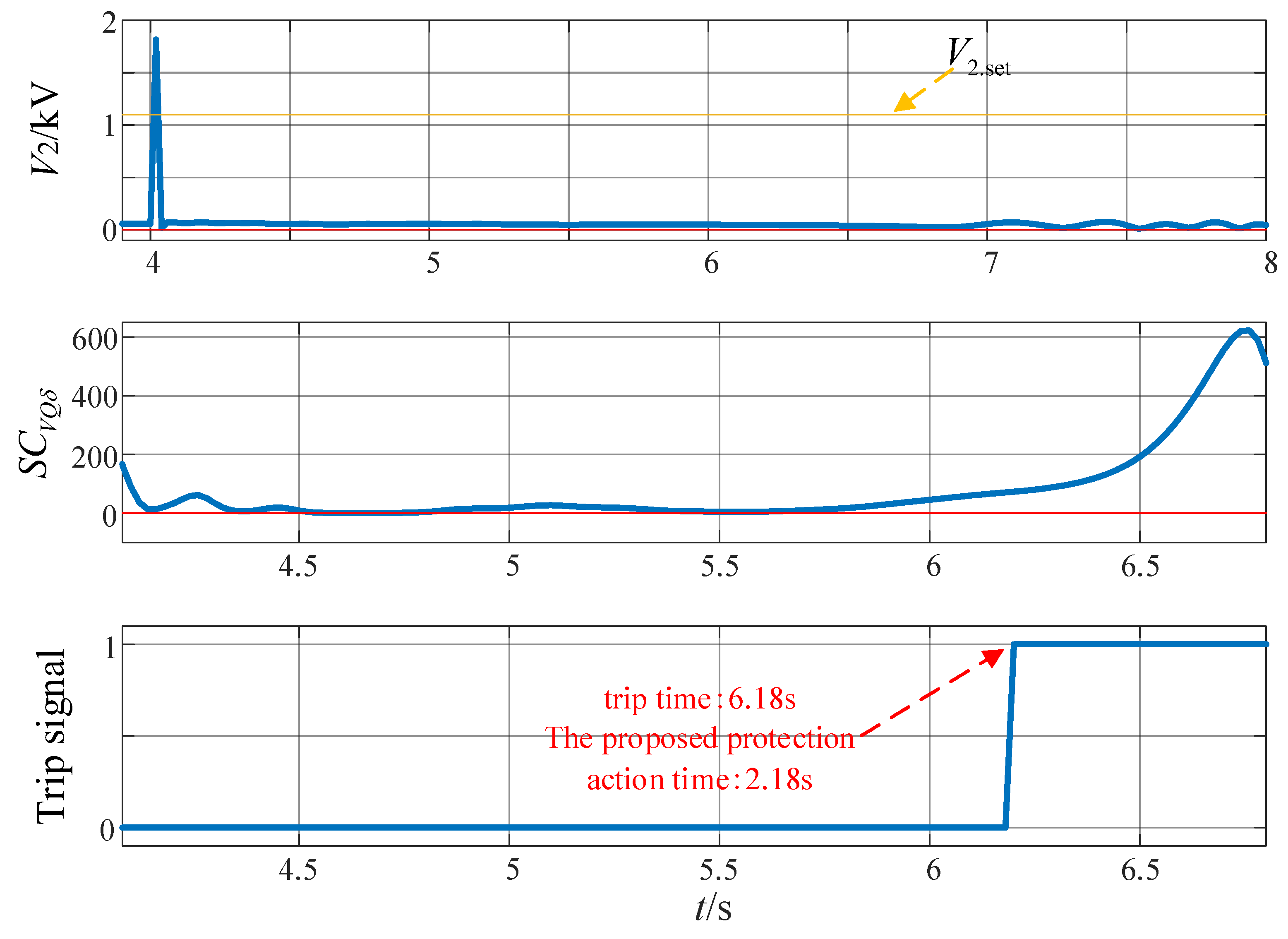
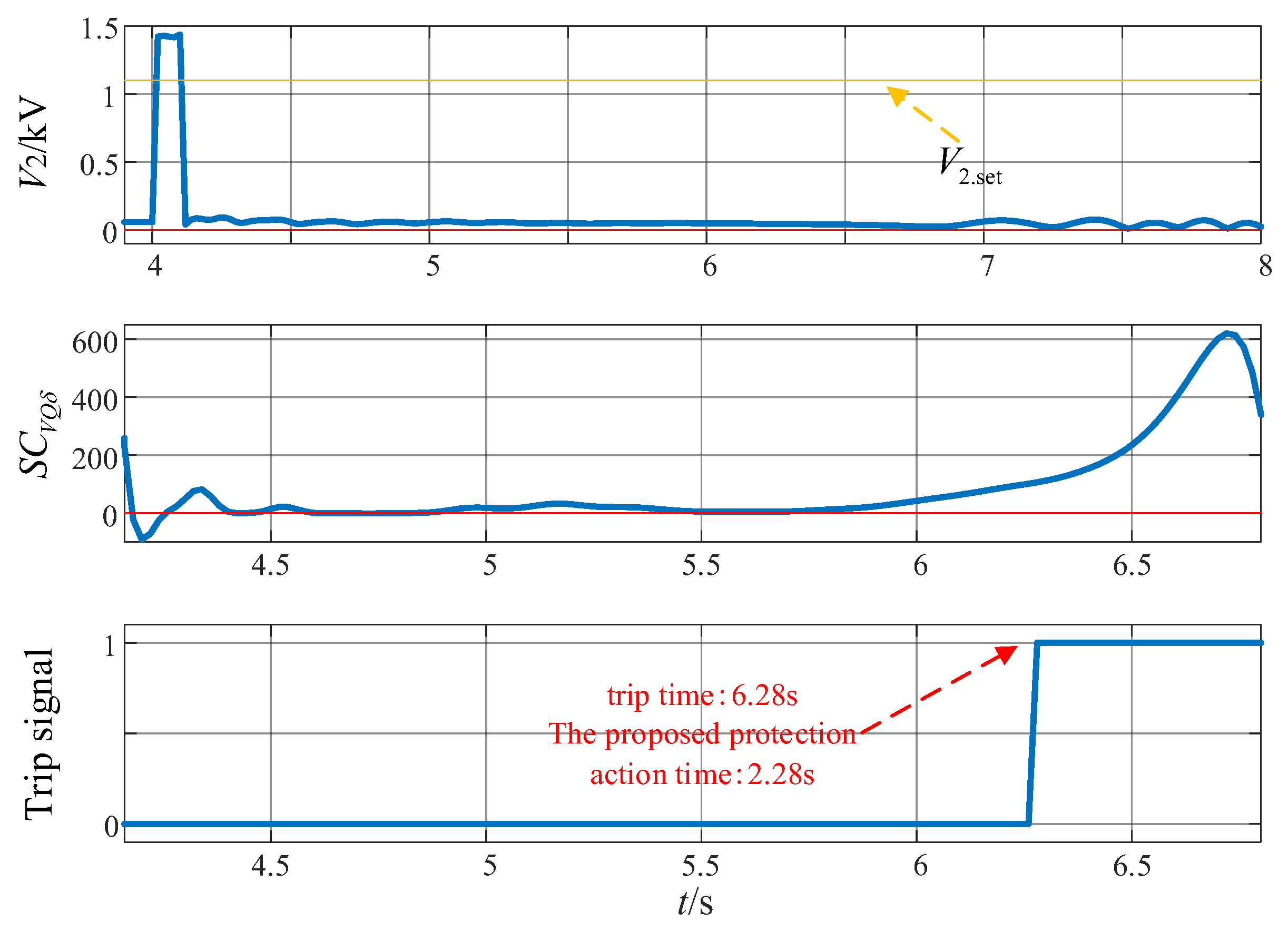
Finally, the operational performance of the protection method proposed in this paper is verified by simulation when the loss-of-excitation fault and the external asymmetric fault occur at the same time. The following simulation scenarios are set: when
t = 4 s, three fault conditions are set at point B in
Figure 7: two-phase short-circuit fault, two-phase short-circuit grounding fault, and single-phase grounding fault. At the same time, the generator is demagnetized. In order to simulate the action process of the line longitudinal differential protection, line 2 is tripped at 20 ms, 20 ms and 100 ms after the fault occurs, respectively. The simulation results are shown in
Figure 14,
Figure 15 and
Figure 16.
The simulation results are in line with the theoretical analysis. During the existence of external asymmetric faults, the negative-sequence voltage is greater than the negative-sequence blocking threshold of the protection, and the protection is temporarily blocked. When the external asymmetric fault is removed, the negative-sequence voltage is less than the threshold, and the protection method proposed in this paper is reopened and tripped. In the three simulation cases, the operating time of the protection is 2.18 s, 2.18 s and 2.28 s, respectively, which is longer than that when only the loss-of-excitation fault occurs, but the protection can still operate reliably. In summary, in the case of simultaneous loss-of-excitation and external asymmetric faults, the negative-sequence voltage blocking element slightly prolongs the operating time of the protection method proposed in this paper (but the quick action is still better than that of the traditional impedance principle loss-of-excitation protection method), but the protection can always operate reliably, and the reliability of loss-of-excitation fault detection does not change.
In general, the introduction of negative-sequence voltage blocking has a positive effect on improving the reliability of protection.
4.5. Influence of Measurement Noise and Communication Delay on Protection Performance
Considering that the core algorithm of the loss-of-excitation protection method proposed in this paper relies on accurate measurements of electrical quantities such as voltage, its protection performance may be affected by measurement noise and communication delays. Systematic evaluation of this impact is a necessary step to ensure the practicability of the method.
Firstly, it is clear that the voltage and other electrical quantities used in the protection method proposed in this paper only consider the fundamental component. In the extraction process, the original signal is first filtered using a low-pass filter, and then the fundamental frequency component is obtained by Fourier decomposition.
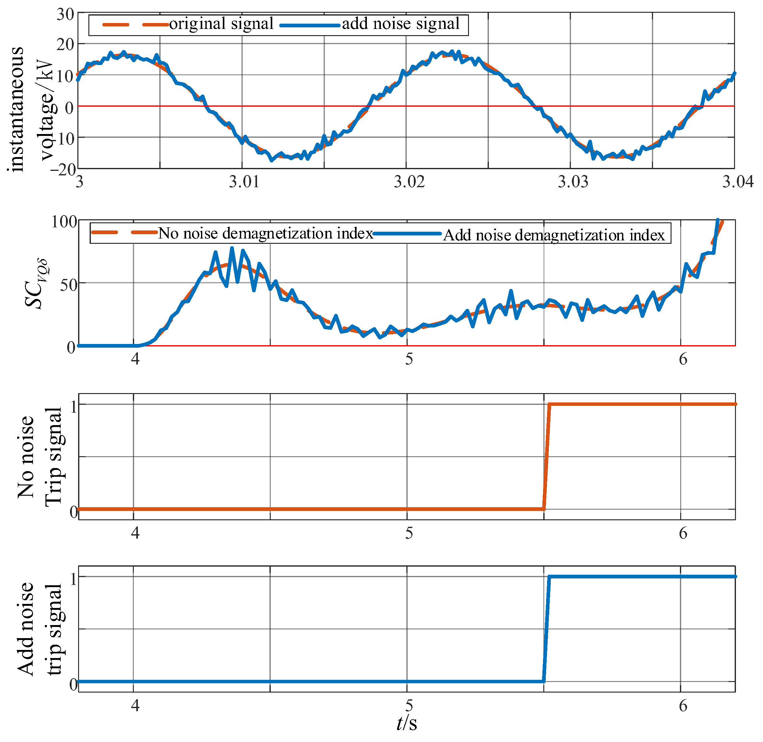
In order to verify the anti-noise interference ability of the proposed protection method, Gaussian white noise [
23,
24,
25] with a mean value of 0 and a signal-to-noise ratio of 20 dB is superimposed on the simulated voltage instantaneous value signal. The comparison with the original signal is shown in the first subgraph of
Figure 17. According to the current national standard document GB/T 19862-2025 [
26], the maximum allowable error of system voltage measurement is ±0.5%, and the corresponding minimum signal-to-noise ratio requirement is about 46 dB. Therefore, the noise interference intensity applied in this experiment was stricter than that of the worst condition of the actual project. The noisy signal is applied to the proposed protection method, and the simulation results are shown in
Figure 17. The results show that although the loss-of-excitation index fluctuates to a certain extent, the overall change trend is consistent with the theoretical analysis, and the protection still operates correctly, which proves that the protection method proposed in this paper has good robustness to measurement noise.
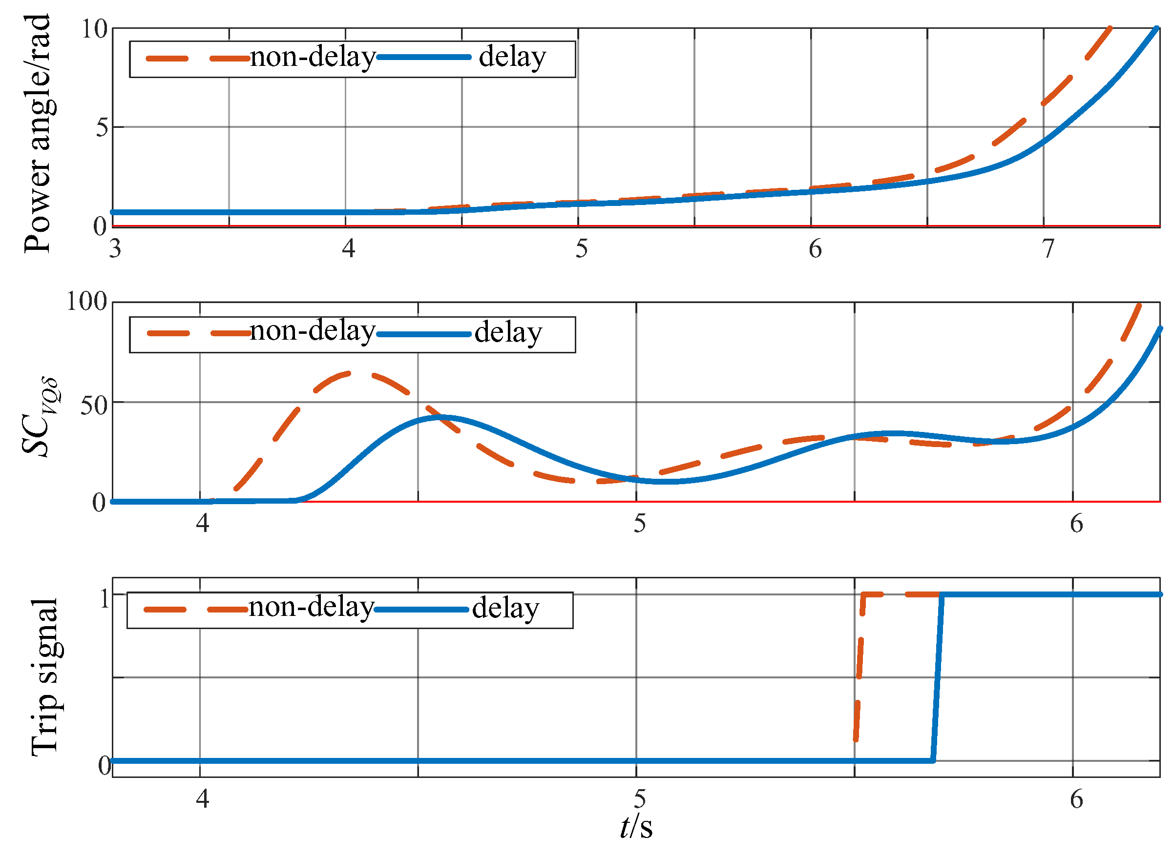
In order to evaluate the impact of communication delays on protection performance, a similar procedure is used to evaluate the influence of a communication delay. In practical engineering, the terminal voltage and power signals are usually collected locally, and the delay can be ignored, while the power-angle signal may be subject to communication delay. To this end, this paper simulates the extreme case where the power angle lags 10 sampling periods (0.2 s). The delay far exceeds the actual possible value for the project and constitutes a harsh test condition. The power angle after delay is applied to the proposed method, and the simulation results are shown in
Figure 18. The simulation shows that the protection can still operate correctly when the protection operating time is increased from 1.5 s without delay to 1.7 s. This is attributed to the fact that the communication delay does not change the basic change trend of the electrical quantity after a loss-of-excitation fault, so the overall change trend of the loss-of-excitation index is maintained. The results show that the proposed method has good tolerance to communication delays.
4.6. Comparison Between the Proposed Protection Method and Loss-of-Excitation Protection Based on the Impedance Principle
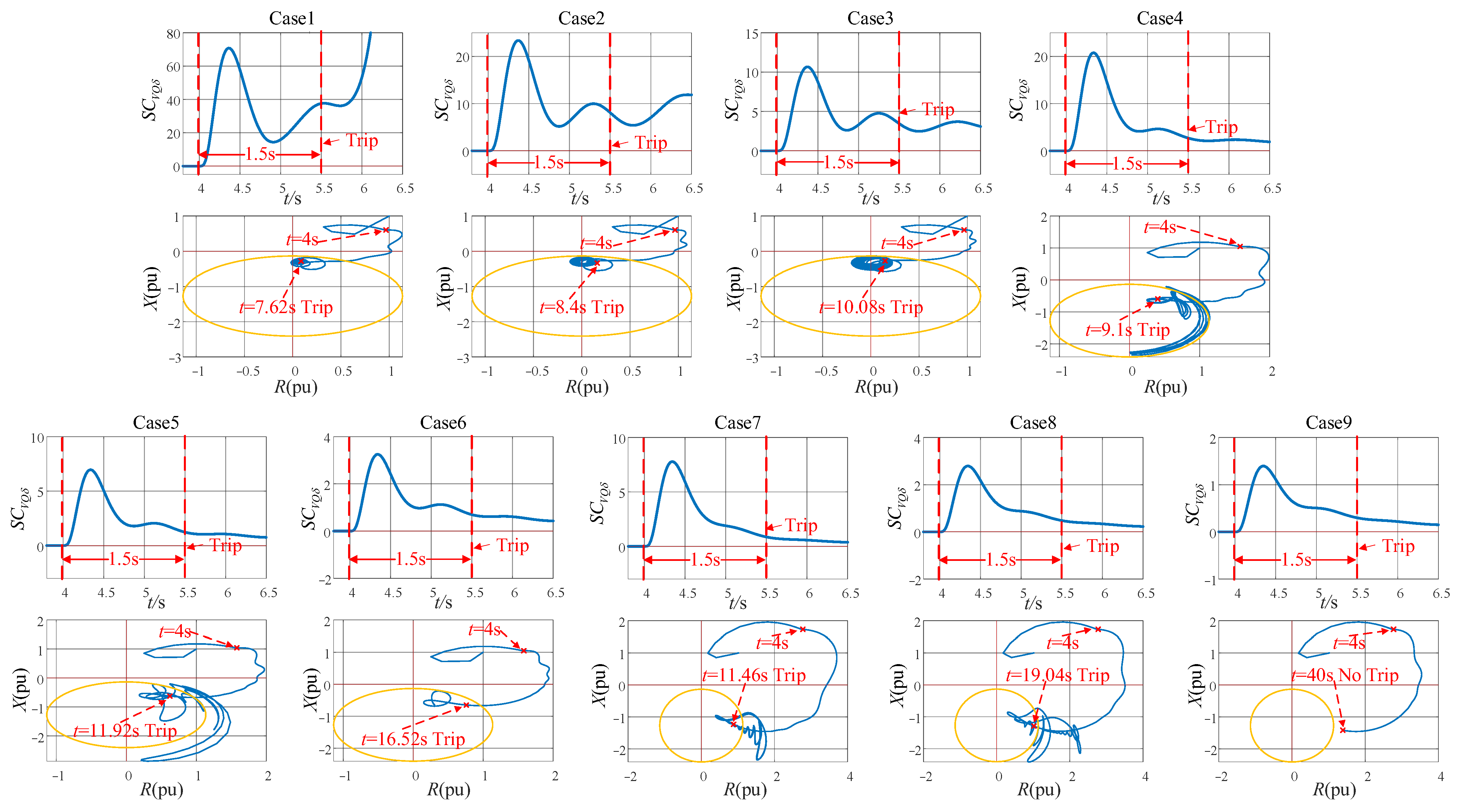
Aiming at the two operating conditions of normal load and light load, the fault of complete loss of excitation and partial loss of excitation are simulated, respectively, so as to compare the difference in operating time between the two protection methods. The loss-of-excitation protection method based on the impedance principle adopts the asynchronous boundary impedance circle as the operating region, and the delay time is set to 1.5 s. The delay time
Tset of the loss-of-excitation protection method based on the variation characteristics of electrical quantities is set to 1.5 s. The specific data for each simulation case are shown in
Table 3.
The comparison of the loss-of-excitation detection of the two protection methods in each case is shown in
Figure 19. The simulation operating time under each case (from loss-of-excitation to tripping) is shown in
Table 4.
Under nine test cases with different load levels and loss-of-excitation degrees, the operating time of the traditional impedance method under eight actionable conditions is 3.62–15.04 s, and the failure to operate occurs in case 9. The protection methods proposed in this paper all complete the action within 1.5 s, and the corresponding operating time reduction ratio is 58.6–90.0%. The simulation results show that when the pumped storage unit is partially demagnetized under light load, the operating time of the loss-of-excitation protection method based on the impedance principle is significantly prolonged, and it shows that the lighter the load, the lower the degree of loss of excitation, the longer the operating time, and even the longer the phenomenon of failure to operate. The protection method proposed in this paper shows very stable performance for action against a loss-of-excitation fault, and is not affected by the load condition of the generator and the degree of loss of excitation. It can act quickly and reliably in all test cases without any failure to operate. Compared with the traditional impedance-based protection method, the operating time is shortened by at least 58.6%, and the proposed method has good loss-of-excitation fault discriminant performance.
The protection method proposed in this paper has certain advantages in terms of speed and reliability of protection, and is also lower than the traditional impedance-based protection method in terms of complexity. The traditional impedance-based protection method contains a variety of criteria, including a stator-side impedance criterion, low-voltage criterion, rotor criterion and reactive-power reverse criterion. Therefore, the traditional impedance-based protection method needs to integrate the terminal voltage, current, excitation voltage and reactive power (sometimes active power) to support its multi-criteria system. The protection method proposed in this paper only needs three electrical quantities: terminal voltage, reactive power and power angle, and the required electrical quantity is less. Secondly, determining whether the impedance trajectory enters the operating region requires complex calculations. However, in the protection method proposed in this paper, the core loss-of-excitation index criterion only involves the direct comparison of scalar size. The algorithm is easy to implement in the microcomputer protection device and has certain advantages in operational speed. In summary, the proposed protection method is simpler than the traditional impedance-based protection method in terms of overall complexity.
4.7. Applicability to Different Rated Capacities and Inertia Time Constants
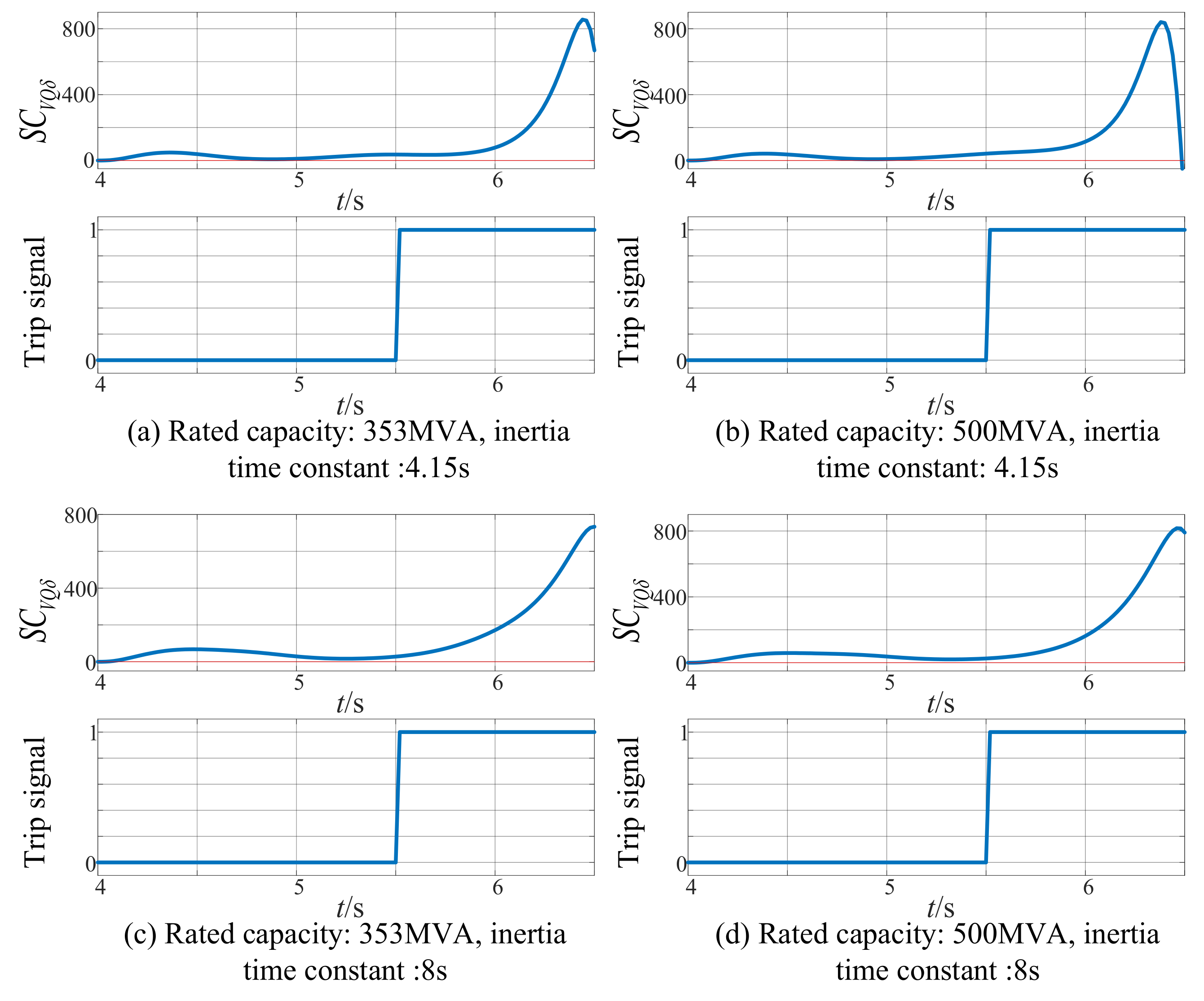
To further validate the applicability of the proposed protection method, supplementary simulation experiments were conducted on pumped storage units with different parameters. Specifically, the rated capacity was set to 353 MVA and 500 MVA, and the inertia time constants were set to 4.15 s and 8 s, resulting in a total of four test groups. In each case, a loss-of-excitation fault was applied at t = 4.0 s. As shown in
Figure 20, the proposed method successfully detects the fault and issues a trip signal at 1.5 s after fault inception (i.e., equal to the preset delay
Tset). These results demonstrate that the proposed protection method remains effective for pumped storage units with varying inertia time constants and rated capacities.
5. Conclusions
In this paper, the variation characteristics of each electrical quantity of the pumped storage unit during loss-of-excitation faults and system oscillations are studied. Aiming at the shortcomings of the traditional impedance principle-based loss-of-excitation protection in protection performance, a loss-of-excitation protection method based on the variation characteristics of electrical quantities is proposed, and the following conclusions are obtained:
(1) The scope of application of the protection method proposed in this paper: According to the current national standard document GB/T 40586-2021 [
27], the configuration requirements for grid-connected protection of synchronous units require that thermal power and nuclear power turbo-generator units with a single unit capacity of 100 MW and above, hydro-generator units and conventional pumped storage units of 40 MW and above, and pumped storage units with 220 KV voltage levels and above be equipped with loss-of-excitation protection. The protection method proposed in this paper is applicable to the above units.
(2) The detection ability of the proposed protection method for loss-of-excitation faults meets the basic requirements for relay protection.
The loss-of-excitation protection method based on the variation characteristics of electrical quantities has good operating speed and sensitivity. Compared with the traditional impedance principle-based loss-of-excitation protection, the proposed method improves the operating speed by 58.6~90.0%. For loss-of-excitation protection based on the traditional impedance principle, the protection operating time is equal to the trajectory development time plus the protection setting time, and the lighter the loss-of-excitation fault and load, the longer the operating time. When a loss-of-excitation fault occurs, the protection method proposed in this paper stably meets the criterion of the loss-of-excitation index, and a trip signal is issued after the preset time delay. The operating time is equal to the setting time and is insensitive to the degree of excitation loss and the load level. For a slight loss-of-excitation fault (low loss of excitation and load), the protection method proposed in this paper can still act quickly, indicating that it has good sensitivity to loss-of-excitation faults.
The loss-of-excitation protection method based on the variation characteristics of electrical quantities meets the reliability requirements of loss-of-excitation protection. Because the delay time Tset is based on the system minimum oscillation frequency fmin setting and the existence of a negative-sequence blocking element, the protection method proposed in this paper has good anti-maloperation performance for system oscillation and internal and external generator asymmetric faults, and ensures that non-loss-of-excitation events do not malfunction. The variation trend of each electrical quantity of the generator after loss of excitation is independent of the degree of loss of excitation and load. The proposed protection method can stably meet the criterion of the loss-of-excitation index, has good discriminant performance for loss-of-excitation faults, and ensures that the loss-of-excitation fault does not cause maloperation.
(3) The protection method proposed in this paper has good engineering promotion conditions: the electrical quantities used in the protection method proposed in this paper are less, and all of them are conventional measurable electrical quantities. The core loss-of-excitation index is based on scalar multiplication, and the criterion only involves simple size comparison. The complexity of the method is simpler than that of the traditional impedance principle-based loss-of-excitation protection method, and the algorithm is easy to implement in microcomputer protection devices. At the same time, under the condition of noise interference with a signal-to-noise ratio of 20 dB or communication delay of 0.2 s, the proposed protection method can still maintain reliable operation, which verifies its strong engineering practicability and anti-interference ability.
(4) Limitations of the protection method proposed in this paper: The core criterion of the protection method proposed in this paper is based on the electrical variation, so it is more suitable for strong power systems with high system inertia. In a weak power system with a high proportion of new energy and low inertia, the protection reliability may decrease slightly, which requires further study. However, with the increasing proportion of new energy in power systems, technologies for enhancing system inertia and grid strength are continuing to mature. Synchronous condensers, virtual pumped storage units, grid inverters and other technologies have effectively improved the inertia of power systems. Moreover, the method proposed in this paper is mainly for large synchronous units, and its near-area power grid is usually a strong power supply system. Therefore, it is suitable for most of the current engineering application scenarios.
Future work will focus on improving the performance of the proposed method under weak-grid conditions.