


Abstract
Parallel converter operation enables flexible capacity expansion of energy-storage power conversion systems. However, parallel converter interactions, filter-inductor saturation, and grid-strength variations increase the risk of resonance instability. The measured current-inductance characteristic is incorporated into an operating-point-dependent closed-loop Norton model. The grid current of an individual converter is decomposed into self-reference, parallel converter coupling, and grid-voltage-disturbance responses. It reveals that converter-side inductance attenuation shifts the internal and parallel resonances to higher frequencies and increases resonance-instability risk, whereas converter number and grid impedance primarily reshape the parallel resonance. A coordinated active-damping method is then developed: PCC voltage feedforward weakens common-network interaction, and capacitor-voltage feedback increases local LCL-filter damping. Simulation and experimental results validate the feasibility and effectiveness of the proposed control method. Experiments with two parallel converters validated the proposed control method. Stable transient current responses were achieved during a simultaneous current-reference step from 50 to 120 A, while the grid-current THD and power-sharing deviation remained below 3% and 5%, respectively.
1. Introduction
With the increasing penetration of renewable energy, power systems require faster power balancing, stronger fluctuation mitigation, and greater operational flexibility. Electrochemical energy storage is well suited to these tasks because of its rapid bidirectional power response [1,2]. The power conversion system (PCS) is the key interface between the storage unit and the grid. For megawatt-class applications, a single conversion stage is often limited by semiconductor current capability, loss distribution, and thermal management. Therefore, high-capacity PCSs are commonly built from several converters connected in parallel on the ac side [3]. This modular structure improves scalability and redundancy. Inductor–capacitor–inductor (LCL) filters are widely adopted owing to their strong switching-harmonic attenuation. However, the common point of coupling (PCC), the individual LCL filters, and the nonzero grid impedance form a high-order electrical network. A converter that is stable when operated alone may consequently exhibit amplified resonance or oscillatory instability after additional modules are connected or the grid impedance changes [4,5].
A system-level model is therefore needed to describe both converter dynamics and network coupling. State-space models retain internal control states and unit-level parameter differences [6]. Multiple input–multiple output transfer matrices describe cross-coupled terminal responses [7]. Nodal-admittance and interaction-admittance models reveal the common and interactive current paths from a network perspective [8]. These formulations suit different converters and complex networks, but their matrix order and parameter requirements increase with system size. Explicit relations between a physical parameter and a resonant mode are then difficult to derive. A grid impedance allocation model maps the common grid impedance into individual converter loops [9], while a closed-loop interconnected model evaluates the interaction strength and its effect on system damping [10]. For nominally identical current-controlled converters, closed-loop Norton-equivalent models provide a lower-order alternative. The current of a target converter is separated into its own reference response, the responses caused by the other converters, and the grid-voltage-disturbance response [4,5]. This form clearly exposes the effects of converter number and grid impedance. Harmonic state-space and multifrequency models have also been developed to characterize the sideband coupling and additional resonant modes caused by asynchronous PWM carriers [11,12]. By synchronizing the sampling instants and PWM carriers across all converters, the relative timing offsets can be removed, and the interactions induced by asynchronous carriers can thus be largely suppressed. Thus, available models provide either detailed but high-order descriptions or transparent lower-order decompositions, but they generally retain fixed filter parameters.
As synchronous generation is increasingly displaced by inverter-based resources connected through long transmission lines and transformers, the grid strength at the PCC is gradually reduced. The short-circuit ratio (SCR) is commonly used as a scalar measure of grid strength. At a fixed converter rating and voltage level, a lower SCR generally corresponds to a larger equivalent grid impedance [13]. The grid can be represented by a Thevenin voltage source behind an RL impedance when grid-strength variation is the main concern. A measured frequency-dependent impedance is preferable when cable, transformer, or compensation resonances must also be represented [13]. Grid impedance effects have been studied through state-space eigenvalue analysis [6], resonance modal analysis of nodal-admittance matrices [14], and impedance-based analysis with the generalized Nyquist criterion [8,9]. However, resonance stability cannot be assessed from the system impedance alone, because the resulting impedance interaction determines both the resonance frequencies and damping characteristics. Moreover, most available analyses investigate grid impedance variations while assuming constant LCL-filter parameters. It is therefore difficult to characterize the combined effects of grid impedance variation and current-dependent filter inductance on the resonance characteristics and stability of parallel converter systems.
To suppress harmonic resonance and improve system stability, various damping methods have been developed. Passive damping is simple and reliable, but it introduces continuous power loss. Feedback-based active damping and terminal-admittance shaping are therefore widely used [15]. Capacitor-current and capacitor-voltage feedback can provide LCL-filter damping without a physical damping resistor [16,17,18], although digital delay and parameter variation affect the effective damping range [19]. PCC voltage feedforward can attenuate the grid-voltage-disturbance path and reshape the converter terminal admittance [20]. For parallel converters, PCC voltage feedforward has been combined with high-frequency grid-current feedback to address the PCC-mediated and local resonant modes [21]. An improved dual-division-summation controller has been combined with parallel virtual admittance and a bandpass filter to suppress multiple resonances in nonsynchronous inverter clusters [22]. Distributed passivity-based control has been proposed for multi-inverter plants subject to grid impedance variation and plug-and-play operation [23], while optimization-based impedance shaping has been developed for multi-parameter tuning of a grid-tied inverter [24]. However, these methods may require resonance-frequency or grid impedance information, parallel converter coordination, or iterative optimization. More importantly, current-dependent filter inductance is not included in their resonance analyses or control-design procedures. In particular, the filter-dependent mode treated as fixed in [22] would shift toward a higher frequency when the inverter-side inductance decreases with current.
For an inductor with soft magnetic saturation, the incremental inductance decreases as the bias current increases. This change shifts the LCL resonance and modifies the current-loop dynamics. Variable inductance has been considered in the common-mode loop of a single modified-LCL-filtered converter [25] and in a grid-forming inverter designed to increase its fault-current contribution [26]. Although magnetic saturation has been shown to reduce stability margins, its effects on current-controlled parallel LCL systems remain insufficiently addressed, as most existing models assume constant filter inductances. The combined effects of the current-dependent inductance, converter number, and common grid impedance remain insufficiently addressed. A damping design based only on the nominal inductance may not retain adequate margins at high current.
To address these gaps, the main contributions of this paper are summarized as follows.
- By incorporating the measured current–inductance characteristic of the converter-side filter inductor, an operating-point-dependent closed-loop Norton equivalent model is established for parallel-connected LCL-type converters. The grid current of an individual converter is decomposed into the self-reference, inter-converter coupling, and grid-voltage-disturbance responses. It is revealed that converter-side inductance reduction shifts both the internal and parallel resonances toward higher frequencies and increases the risk of resonance instability, whereas the number of parallel converters and grid impedance primarily influence the parallel-resonance characteristics.
- A coordinated active-damping method is proposed for the two resonant paths. PCC voltage feedforward reduces the interaction through the common network, while capacitor-voltage feedback increases the local damping of each LCL filter. A parameter-design procedure is established over the investigated ranges of inverter-side inductance, converter number, and grid strength. Simulation and experimental results verify stable parallel operation during current-reference steps and grid-strength variations.
The remainder of this paper is organized as follows. Section 2 presents the parallel energy-storage converter, develops the operating-point-dependent filter-inductor and closed-loop Norton models, and analyzes the effects of inductance reduction, parallel converter number, and grid strength. Section 3 introduces the coordinated active-damping method and its parameter-design procedure. Section 4 presents the simulation and experimental validation. Section 5 summarizes the main conclusions.
2. Modeling and Resonance Mechanism of the Parallel Converter System
2.1. System Configuration and Current-Dependent Filter Inductance
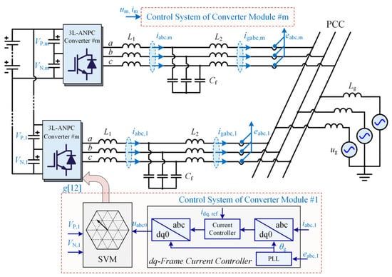
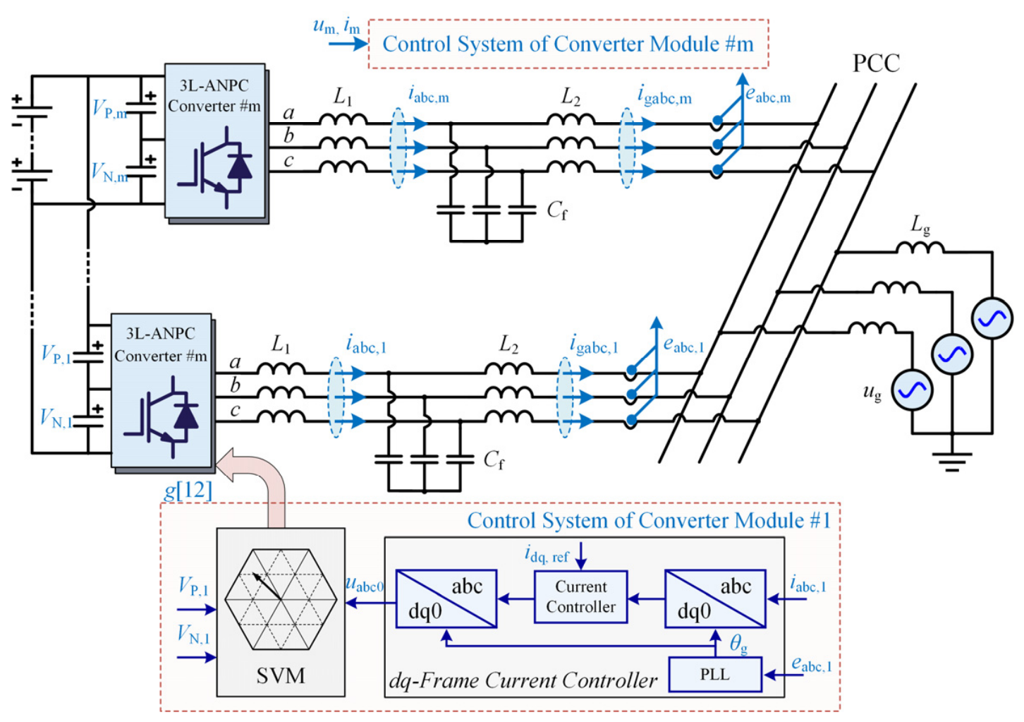
Figure 1 illustrates N identical grid-connected converters connected in parallel to common dc and ac buses. Each converter j, j ∈ {1, 2, …, N}, is interfaced with the PCC through an individual LCL filter comprising L1,j, L2,j, and Cf. The variables uo,j, i1,j, uc,j, and ig,j denote the averaged bridge output voltage, inverter-side current, capacitor voltage, and grid-side current, respectively. Additional feeder impedances between the filter outputs and the PCC are neglected. Each converter employs the same inverter-side-current control structure. The synchronous angle is extracted from the PCC voltage by a phase-locked loop, while the outer power controller generates the dq-axis current references, and i1,j is used as the inner-loop feedback variable. The sampling instants and PWM carriers of all converters are synchronized through communication.
Figure 1.
System configuration and control architecture of the parallel LCL-type grid-connected converters.
Soft-magnetic powder-core inductors are widely used in high-power converters because of their high power density and favorable thermal stability. However, the effective permeability decreases gradually under soft saturation as the inductor current increases. The filter inductance therefore exhibits a continuous reduction. A constant inverter-side inductance cannot accurately represent the converter dynamics over a wide power range, especially under high-current operation.
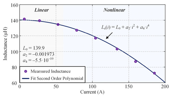
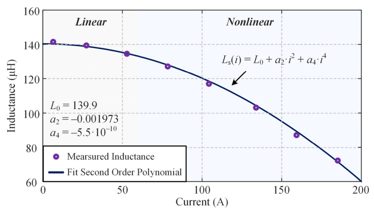
As shown in Figure 2, discrete inductance data at different current magnitudes were first obtained through offline single-pulse testing of the prototype converter-side inductor. Owing to the approximate symmetry of the saturation characteristic with respect to current polarity, the current-dependent inductance is commonly represented by an even-order polynomial [26]. Accordingly, the measured data were initially fitted by least squares using the following fourth-order polynomial model:
where L0 denotes the inductance at zero current, and a2 and a4 are the fitted coefficients. As illustrated in Figure 2, the second- and fourth-order fitting curves are nearly coincident over the investigated current range, indicating that the contribution of the fourth-order term a4 is negligible. Therefore, this term is omitted in the subsequent analysis to reduce the model complexity without compromising the fitting accuracy. The current-dependent inductance is thus expressed as:
Figure 2.
Measured and fitted current-dependent inductance characteristics of the prototype converter-side inductor.
Neglecting mutual coupling among the three-phase inductors, the corresponding phase flux linkages are obtained by integrating the incremental inductance:
For balanced positive-sequence currents, the standard Park transformation is applied to (3). Omitting the routine transformation steps, the fundamental dq-axis flux linkages are expressed as:
For balanced positive-sequence currents, the flux-linkage vector is transformed into the synchronous reference frame and linearized at the operating-current amplitude I, yielding:
For an inductor with soft saturation, the second-order fitting coefficient normally satisfies a2 < 0. Both L1d and L1q therefore decrease as the operating current increases, and the d-axis incremental inductance decreases faster than the q-axis inductance. Because the dq-axis dynamic models have the same mathematical structure, L1(I) is used hereafter to denote the operating-point-dependent inductance on either axis. The inductance attenuation coefficient is defined as
where L1N is the inverter-side filter inductance at the rated or low-current operating point.
The instantaneous inductance varies continuously with current. The present analysis does not focus on intracycle harmonics caused by magnetic nonlinearity. Instead, the influence of inductance attenuation at different steady-state current levels on the parallel-system resonance is investigated. At each steady-state operating point I = I0, L1(I0) is therefore treated as a locally constant parameter, and a linear time-invariant model is established for that operating point. The operating-current variation is introduced explicitly into the closed-loop and multi-converter models through kL.
2.2. Closed-Loop Norton Model of a Single Converter
A single-converter model with inverter-side current feedback is established using the current-dependent inductance described above. In the synchronous reference frame, the fundamental-frequency cross-coupling terms are normally compensated in the current controller. In addition, the LCL resonance frequency considered here is much higher than the grid fundamental frequency. After conventional decoupling, the d- and q-axis models have the same basic structure. One decoupled axis is therefore analyzed, and the axis subscript is omitted. The equivalent per-axis model of the three-phase LCL-type converter is written as:
From (7), i1 and uo can be further expressed as functions of ig and uPCC:
The transfer functions HLCL(s, L1) and A(s, L1) are defined as:
Considering the digital-control delay Gd(s) and the modulator gain KPWM, the complete current-control channel is defined as:
The current-control law is given by:
By substituting (8) into the control law and rearranging the result, the following closed-loop relationship is obtained:
In (12), Φ(s) is the controlled-current-source transfer function of the Norton model, and Yo(s) is the equivalent output admittance. They are expressed as:
where
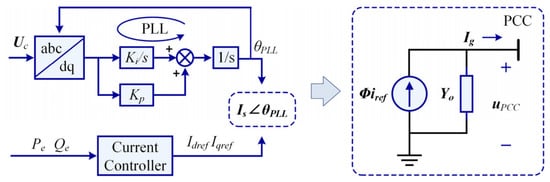
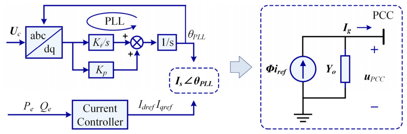
According to (14), a converter with inverter-side current feedback can be represented by the parallel connection of the controlled current source Φ(s, L1)iref and the closed-loop output admittance Yo(s, L1), as shown in Figure 3. The transfer function Φ describes the closed-loop response from the current reference iref to the grid current ig, whereas Yo describes the influence of the PCC voltage disturbance on the grid current. The closed-loop Norton representation incorporates the internal control dynamics and the external electrical network into a single terminal model. It is therefore suitable for extension to the parallel converter system.
Figure 3.
Closed-loop Norton equivalent model of a single converter.
It should be noted that the operating-point-dependent inductance L1(I) appears in D0, Q, Φ, and Yo. Inductance attenuation under high-current operation changes not only the natural resonance of the passive LCL network but also the closed-loop current transfer and the converter terminal characteristic. Therefore, inductance attenuation cannot be represented only as a passive-parameter variation in the multi-converter analysis.
2.3. Closed-Loop Equivalent Model and Grid-Current Decomposition of the Parallel System
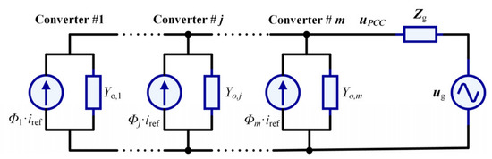
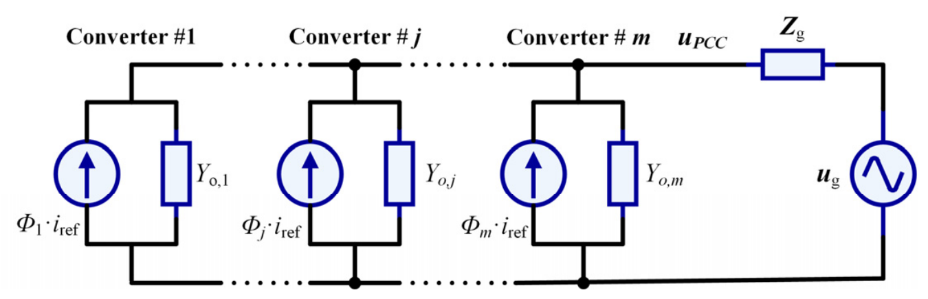
The single-converter Norton model is extended to N paralleled energy storage converter modules, as shown in Figure 4.
Figure 4.
Closed-loop Norton equivalent circuit of paralleled converters connected to the grid through the common impedance Zg.
For converter j, the closed-loop terminal relationship is given by:
where Φj and Yo,j are the controlled-current-source coefficient and the output admittance of converter j, respectively. Both terms depend on the operating-point inductance L1,j(Ij).
By summing the currents of all converters, the PCC voltage is obtained as:
The PCC voltage is determined by the grid voltage and by the controlled current sources of all parallel converters. The term 1 + ZgYΣ characterizes the closed-loop interaction between the parallel converter system and the common grid.
When Zg ≠ 0, a change in the current reference of any converter is transferred to the other converters through the PCC voltage, and intermodule coupling is produced. When Zg approaches zero, the PCC behaves as a stiff voltage source. The output-current variation of one converter then has little influence on the other converters, and the converters are approximately decoupled. As the grid impedance increases, the current variation in one converter produces a larger PCC voltage disturbance. This disturbance is reinjected into the grid currents of the other converters through their output admittances. Hence, the common grid impedance changes the equivalent resonant network and also provides the physical coupling path among the converters.
According to the multi-converter equivalent circuit in Figure 4, the terminal characteristic of one energy storage converter is affected by the other parallel converters and by the grid impedance. Nodal analysis gives the grid current of a target converter as:
where
The corresponding transfer functions are defined as:
Gself,k describes the effect of the current reference of the target converter on its own grid current. This response includes the direct action of the single-converter current loop and the indirect feedback produced when the target current changes the PCC voltage through the grid impedance. Therefore, under a weak grid, the response of the target converter is no longer identical to the closed-loop response of an isolated single-converter system.
Gpara,kj describes the effect of the current-reference variation of parallel converter j on the grid current of target converter k. The current variation of converter j first changes the total current flowing through the common grid impedance and thereby perturbs the PCC voltage. The perturbed PCC voltage is then reinjected into the target current through Yo,k. This coupling path depends simultaneously on the controlled-source characteristic Φj of the disturbing converter, the output admittance Yo,k of the target converter, and the common grid impedance Zg. The converters are approximately decoupled under an ideal stiff grid, whereas their coupling is strengthened as the grid impedance increases.
Ggrid,k describes the transfer from the common grid-voltage disturbance to the grid current of the target converter. Grid background harmonics, voltage transients, and PCC voltage disturbances produced by other grid-connected equipment can excite the parallel system through this path. When the network interaction term in the denominator approaches a resonant condition, a small high-frequency grid-voltage disturbance can be strongly amplified in the grid current.
The converters considered in this paper have the same power circuit, filter parameters, and control algorithm. Therefore, Φj = Φ and Yo,j = Yo are used when the general variation of the modular system is analyzed.
The multi-converter network characteristic factor is defined as:
Equation (20) can then be simplified as:
When the other N − 1 converters are subjected to in-phase disturbances, their aggregated coupling effect on the target converter is expressed as:
Equation (22) shows that the parallel system is governed mainly by two characteristic factors. D0 is determined by the LCL parameters, current controller, and digital-control delay of one converter. It represents the inherent closed-loop dynamics of the single-converter system. DN further includes the number of parallel converters and the grid impedance and therefore represents the interaction between the converters and the common grid.
Both Gself and Gpara contain D0 and DN. Their frequency responses can therefore exhibit the local LCL resonance and the network-coupled resonance at the same time. By comparison, Ggrid is governed mainly by DN. Each resonant phenomenon is explained from the actual current-transfer path and the corresponding closed-loop characteristic factor.
2.4. Effects of Inductance Attenuation, Converter Number, and Grid Strength
According to (21), the inverter-side filter inductance L1, the number of parallel converters N, and the grid impedance Zg affect the parallel-system resonance through different paths. The inductance L1 appears in D0, Q, and DN and therefore changes both the single-converter closed-loop dynamics and the network interaction. The parameters N and Zg mainly affect DN through the network interaction term. To obtain the migration directions of the resonance frequencies, the parasitic resistances are neglected temporarily, and the small displacement of the resonant center frequency caused by the controller is neglected near resonance.
The approximate resonance frequency of one LCL filter is:
For an inductive grid, Zg = sLg, the approximate resonance frequency associated with the network characteristic factor is
For a soft-saturating inductor, dL1/dI < 0. The local LCL-resonance expression and the network-coupled resonance expression therefore show that both resonances move toward higher frequencies as the inverter-side inductance decreases.
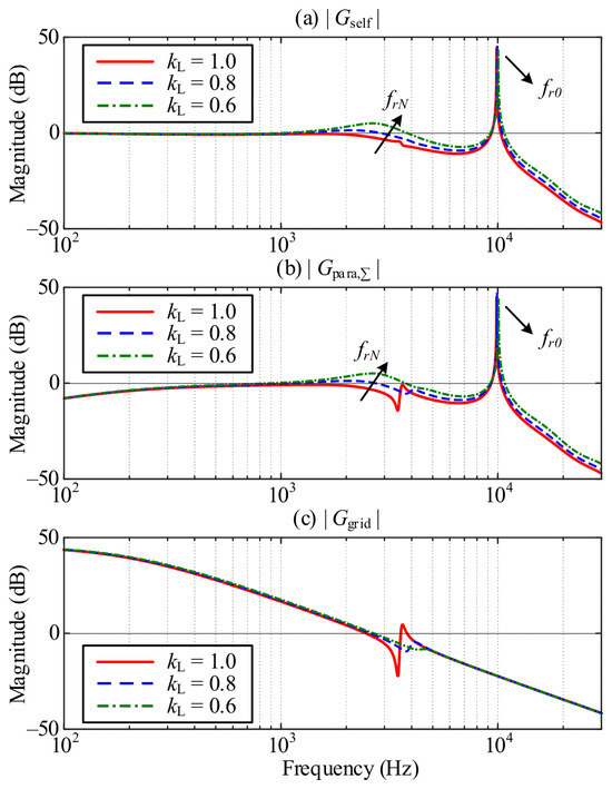
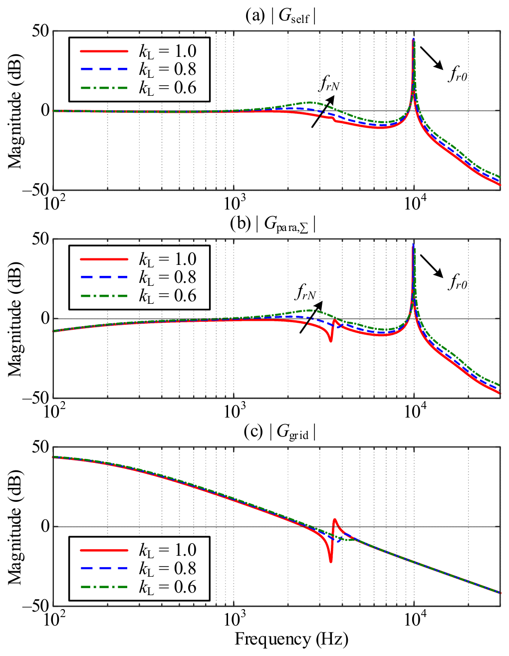
Figure 5 compares the three current-transfer paths for kL = 1.0, 0.8, and 0.6 at SCR = 10. In Gself, the local LCL resonance and the network-coupled resonance move toward higher frequencies as kL decreases. The high-frequency magnitude also increases, which indicates a larger amplification of high-frequency current components. Because the grid-side filter inductance is relatively small, the displacement of the local LCL resonance is limited. In Gpara, two resonance peaks become evident after the inductance is reduced. These peaks can increase the high-frequency circulating current among the parallel converters and reduce the stability of parallel operation. In Ggrid, the cutoff frequency increases as kL decreases, and the influence of the grid impedance becomes more pronounced.
Figure 5.
Effect of inverter-side inductance attenuation on the target current-transfer paths: (a) self-reference response|Gself|; (b) parallel converter coupling response |Gpara,∑|; (c) grid-voltage-disturbance response |Ggrid|.
The effect of the number of parallel converters is obtained from (24) as:
Thus, an increased number of parallel converters mainly moves the network-coupled resonance toward lower frequencies, whereas the local LCL resonance frequency is not directly affected by N.
In addition, the following relationship is obtained:
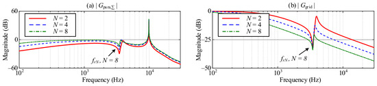
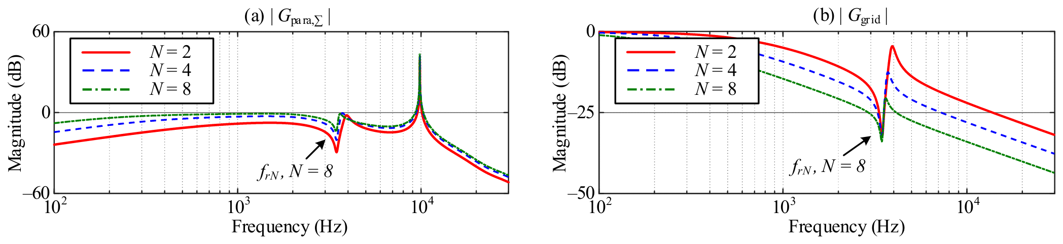
The increase in N has two effects. The number of potential coupling sources is increased, and the network interaction term is strengthened, as shown in Figure 6.
Figure 6.
Effect of the number of parallel converters on the network-coupled responses: (a) parallel converter coupling response |Gpara,∑|; (b) grid-voltage-disturbance response |Ggrid|.
For the grid impedance, the grid strength is represented by the SCR, and the following relationship is used:
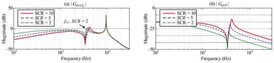
As the grid impedance increases, or equivalently as the grid strength decreases, the network-coupled resonance moves toward lower frequencies. The expression of Gpara also shows that the coupling effect of the other converters approaches zero when Zg approaches zero. The grid impedance therefore determines both the location of the network-coupled resonance and the physical interaction path among the parallel converters, as illustrated in Figure 7.
Figure 7.
Effect of grid strength on the network-coupled responses at a fixed number of parallel converters. (a) parallel converter coupling response |Gpara,∑|; (b) grid-voltage-disturbance response |Ggrid|.
The preceding analysis shows that inductance attenuation, the number of parallel converters, and grid strength affect system resonance through different mechanisms. Inductance attenuation modifies both the single-converter characteristic factor D0 and the network characteristic factor DN, shifting the resonances toward higher frequencies and increasing the phase-lag effect of the digital-control delay. In contrast, increasing the number of parallel converters or reducing the grid strength mainly strengthens the network interaction and shifts the network-coupled resonance toward lower frequencies. Therefore, the resonance frequency varies over the practical operating range rather than remaining fixed at the nominal design point. A damping parameter designed only for the nominal LCL resonance cannot provide sufficient damping under high-current, multi-converter, and weak-grid conditions. The internal damping of the LCL filter must be increased to address the upward resonance shift caused by inductance attenuation, while the PCC terminal characteristic must be reshaped to weaken the network interaction caused by parallel operation and grid impedance. Accordingly, the next section develops a coordinated active-damping method that acts on both the internal filter dynamics and the external network interaction.
3. Global High-Frequency Resonance Suppression for the Parallel Converter System
3.1. Principle of Coordinated Active-Damping Method
The resonance analysis in Section 2 shows that the parallel converter system contains two damping targets with different physical origins. Inductance attenuation modifies both the single-converter characteristic factor D0 and the network characteristic factor DN, and therefore shifts the local LCL resonance as well as the network-coupled resonance. By contrast, the number of parallel converters and the grid impedance mainly affect DN and strengthen the interaction through the common PCC. Consequently, an auxiliary control path acting only on the converter terminal or only on the internal LCL filter can not provide consistent damping over the complete resonance-frequency range.
To address the two resonance mechanisms, a coordinated active-damping structure combining PCC voltage feedforward and filter-capacitor-voltage feedback is adopted. The PCC voltage is a common electrical variable shared by all converter modules. Its high-frequency component reflects the aggregate current interaction through the common grid impedance and is therefore suitable for reshaping the converter terminal admittance and the network characteristic factor. However, this path does not directly modify D0. The filter-capacitor voltage, in contrast, is a local state variable that directly represents the energy exchange among L1, Cf, and L2. Feeding back its high-frequency component modifies the internal characteristic factor and provides additional damping for the local LCL resonance.
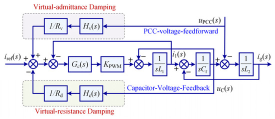
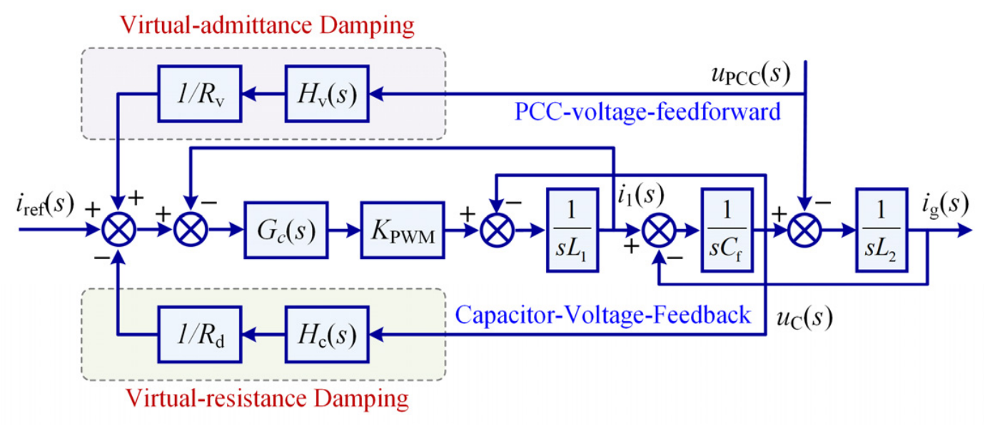
The complete control structure is shown in Figure 8. According to the current direction and summing convention adopted in Section 2, the PCC voltage component is positively fed forward to the current reference, whereas the capacitor-voltage component is negatively fed back. The modified current reference is therefore expressed as:
Figure 8.
Control structure of the proposed coordinated active-damping method.
The high-pass filters in Fv(s) and Fc(s) attenuate the fundamental-frequency components and confine the auxiliary control action to the resonance-frequency range. Both damping signals are injected through the existing current-reference channel and require only the PCC voltage and filter-capacitor-voltage measurements. The two paths are analyzed separately in the following subsections before their coordinated effect and parameter design are discussed.
3.1.1. PCC Voltage Feedforward Virtual-Admittance Damping
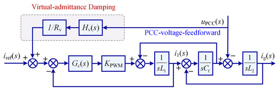
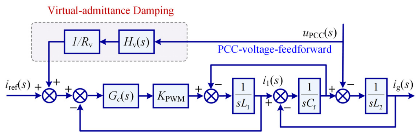
The PCC voltage path is considered first, as shown in Figure 9. Since the currents of all converters jointly determine the PCC voltage through the common grid impedance, the high-frequency PCC voltage component provides a direct measure of the external network interaction. With the current direction defined from the converters to the grid, this component is positively added to the current reference through Fv(s).
Figure 9.
Control structure of the PCC voltage feedforward virtual-admittance damping.
The high-pass filter and the feedforward function for the PCC voltage are defined as
where Rv is the virtual damping parameter associated with the PCC voltage feedback path.
The modified current reference is:
Substituting (31) into the single-converter model, the output admittance with PCC voltage feedforward is obtained as:
For N identical converters, the network characteristic factor is therefore changed to:
A comparison between (32) and (20) shows that PCC voltage feedforward does not directly change the single-converter characteristic factor D0. Instead, the network characteristic factor is modified by an additional output admittance. Hence, this path mainly acts on the interaction between the parallel converters and the common grid rather than on the local LCL resonance. When a high-frequency oscillatory component appears in the PCC voltage, an additional current reference related to this disturbance is generated. The high-frequency terminal-current response of the converter is thereby modified. Within an appropriate parameter range, the additional response is equivalent to a frequency-selective resistive component at the PCC. The resonance amplification produced by the other converter currents and by grid background harmonics can consequently be reduced.
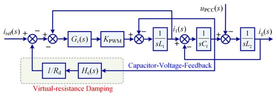
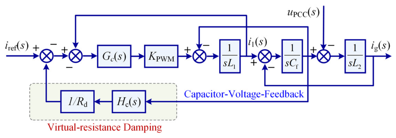
3.1.2. Capacitor-Voltage Feedback Virtual-Resistance Damping
PCC voltage feedforward effectively reshapes the external network interaction and suppresses the network-coupled resonance. However, because it does not directly modify the single-converter characteristic factor D0, it cannot fully damp the local LCL resonance, particularly when the resonance frequency shifts because of inductance attenuation. Therefore, high-frequency filter-capacitor-voltage feedback is added to the PCC voltage feedforward path to increase the internal damping of each LCL filter, as shown in Figure 10.
Figure 10.
Control structure of capacitor-voltage feedback virtual-resistance damping.
The high-pass filter and the feedback function for the capacitor voltage are defined as:
where Rd is the virtual damping resistance associated with the capacitor-voltage feedback path.
Under coordinated damping, the current reference is given by
After the capacitor-voltage state relation is substituted into the closed-loop model, the single-converter characteristic factor and output admittance under coordinated active damping are obtained as:
The corresponding multi-converter network characteristic factor is
Equations (35) and (36) show that capacitor-voltage feedback directly modifies D0,d and thereby increases the internal damping of the LCL filter. It also participates in reshaping the terminal characteristic through Qd and Yo,d. Therefore, PCC voltage feedforward and capacitor-voltage feedback are not completely independent control paths. They act primarily on different resonance mechanisms while jointly changing the multi-converter system.
Within the resonant band, the high-pass filter has approximately unity gain. Under ideal current tracking, the equivalent admittance of the filter-capacitor branch is then approximated by:
Thus, the high-frequency capacitor-voltage feedback is approximately equivalent to a virtual resistance Rd connected in parallel with the filter capacitor in the resonant band.
Using the damping-ratio relationship of the ideal LCL network, the virtual damping resistance is selected as:
The appropriate virtual damping resistance is not a fixed constant but depends on the actual inverter-side filter inductance. Because the analytical value of Rd varies with L1, a fixed Rd should be selected to provide sufficient damping over the prescribed inductance range.
3.2. Robust Parameter Design Considering Inductance Attenuation, Converter Number, and Grid Strength
The preceding analysis shows that Rd mainly determines the internal damping of the LCL filter, whereas Rv mainly reshapes the multi-converter network interaction. Because the two parameters have different physical roles, an undifferentiated two-dimensional parameter sweep is not used. Instead, a coordinated procedure consisting of local-damping initialization, network-damping tuning, and complete closed-loop verification is adopted. This procedure avoids an empty feasible region caused by imposing excessive constraints on both parameters at the same time. Physically meaningful initial parameters are first obtained, and sufficient stability margin over the practical operating range is then verified with the complete closed-loop model.
The frequency ranges of the two feedback paths are determined first. For the first-order high-pass filters defined in the preceding subsections, a small gain is required at the fundamental frequency, whereas sufficient gain must be retained at the lowest resonance frequency of interest.
Accordingly, the following frequency-domain constraints are imposed:
For the PCC voltage path, ωr,min is selected as the lower boundary of the network-coupled resonance band. For the capacitor-voltage path, ωr,min is selected as the lower boundary of the local LCL resonance band. The fundamental component is thereby attenuated, while the main moving resonance bands remain covered by the additional damping.
According to the system parameters and the resonance-frequency ranges obtained in Section 2.4, the cutoff frequencies are selected as fhv = 600 Hz for the PCC voltage feedback and fhc = 1 kHz for the capacitor-voltage feedback.
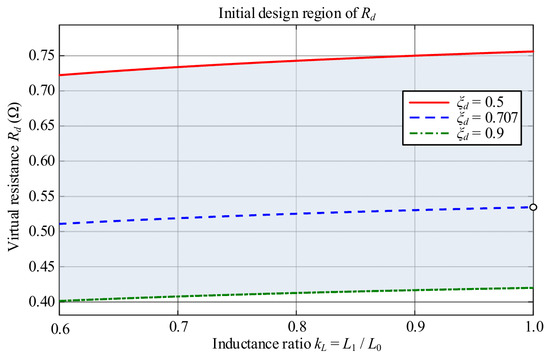
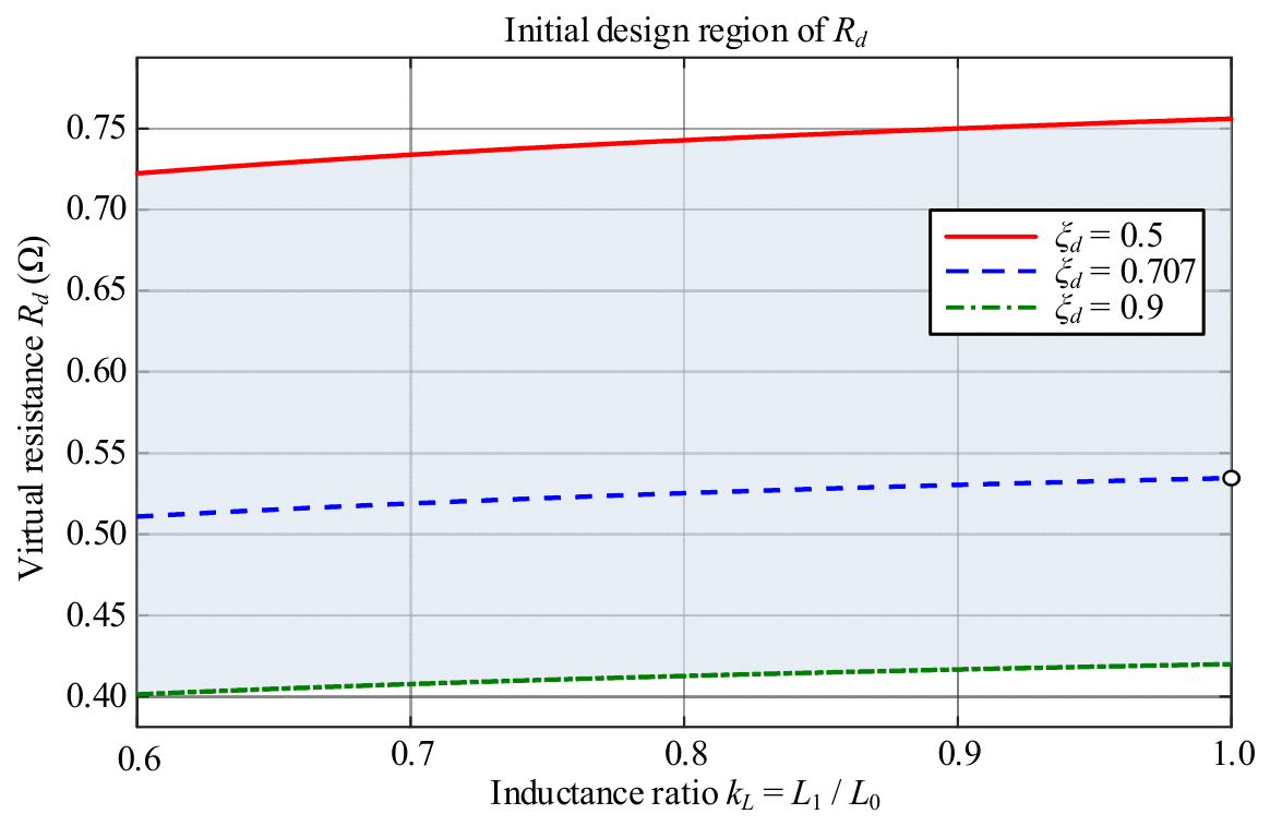
The variation of Rd with kL is then calculated from (38). The damping ratios ξd = 0.5, 0.707, and 0.9 are used to obtain the corresponding Rd ranges under different levels of inductance attenuation.
Equation (38) gives the analytical relationship between Rd and L1. Because L1 = kLL1N, the appropriate virtual-resistance range changes as the inductor saturates, as shown in Figure 11.
Figure 11.
Initial range of Rd versus the inductance attenuation coefficient for different damping ratios.
This region is used only to determine a physically reasonable initial range. The final parameters must be verified with the complete closed-loop model. After the initial Rd range has been obtained, Rd and Rv are tuned over the operating domain Ω. Classical gain margin, phase margin, and closed-loop pole location are used as stability constraints. To avoid introducing nonstandard stability indices, the maximum resonance peak of Gself,d and the minimum phase margin of the local damping loop are evaluated as:
As the damping action is strengthened, the local resonance peak normally decreases. Excessive feedback, however, increases the phase effect of the digital delay. Rd* should therefore be selected where the local resonance has been effectively suppressed, and the local loop still retains sufficient phase margin.
After Rd = Rd* has been fixed, the PCC voltage feedback parameter Rv is tuned. For each candidate Rv, the worst-case network-coupled resonance peaks of Gpara,Σ,d and Ggrid,d are compared over the practical operating range, and the minimum phase margin of LN(s) is evaluated as:
As Rv decreases, the PCC voltage feedback is strengthened, and the network-coupled peak is normally reduced. Excessive terminal feedback can nevertheless increase the high-frequency phase lag. Therefore, Rv should be selected in a compromise region where the network-coupled resonance is clearly suppressed without a significant reduction in stability margin.
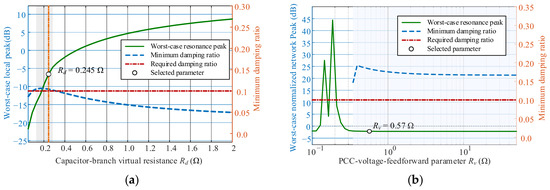
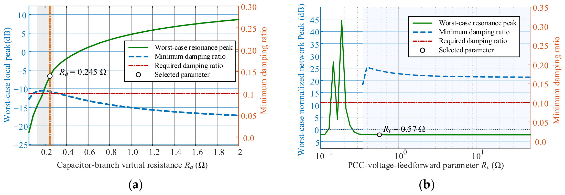
Figure 12 summarizes the sequential robust design of the two damping parameters. A direct two-dimensional search in the Rv−Rd plane is not adopted because the two parameters act primarily on different characteristic factors and simultaneous constraints can obscure their individual physical roles. Instead, Rd is first selected from the local LCL dynamics, after which Rv is selected from the external network interaction with Rd fixed.
Figure 12.
Robust design of coordinated active-damping parameters. (a) Selection of Rd; (b) selection of Rv.
In Figure 12a, the worst-case local resonance peak of Gself,d and the minimum damping ratio of the local damping loop are evaluated as Rd varies over the prescribed inductance range. The shaded interval satisfies the closed-loop pole-location, gain-margin, and minimum damping ratio requirements. The value Rd* is selected within this interval to minimize the worst-case local resonance peak while retaining the required stability margin.
In Figure 12b, Rd is fixed at Rd*, and Rv is swept over the complete operating domain Ω = {kL, N, SCR}. The worst-case network resonance peak is defined as the larger of the peaks in Gpara,∑,d and Ggrid,d within the network-coupled resonance band, while the minimum damping ratio is obtained from the network loop LN(s) = NZg(s)Yo,d(s). The selected Rv* minimizes the worst-case network resonance peak within the feasible interval. The corrected positive PCC voltage feedforward sign is included through Qd = Q + Gi(Fc(s) − Fv(s)).
Based on the prescribed resonance-peak and pole-damping constraints, Rd = 0.245 Ω and Rv = 0.57 Ω are selected. At the selected parameters, the worst-case local and normalized network resonance peaks remain below 0 dB, while the minimum damping ratios are higher than 0.1 over the investigated operating range.
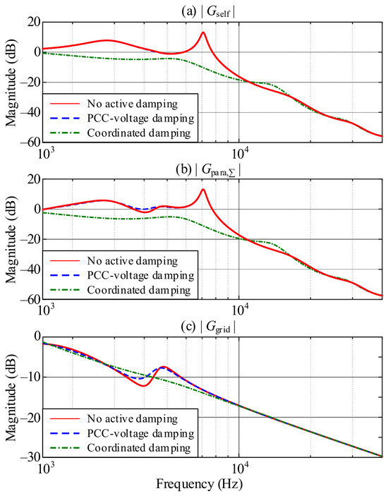
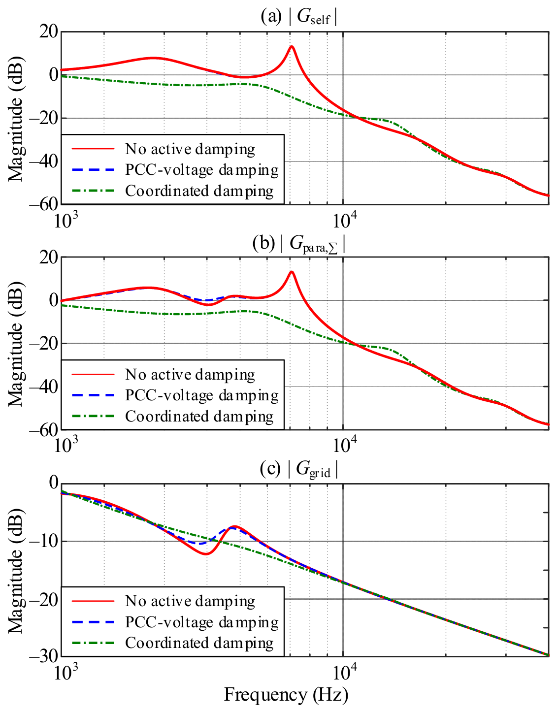
Figure 13 compares the resonance responses without active damping, with only PCC voltage feedforward, and with coordinated active damping. When only PCC voltage feedforward is enabled, D0 remains unchanged, whereas Qv and the corresponding network characteristic factor DN,v are reshaped. With the selected Rv*, the network-coupled peak and the grid-voltage-disturbance response are reduced. After capacitor-voltage feedback is also enabled, D0,d is modified, and the local LCL resonance is further damped. Therefore, PCC voltage feedforward primarily weakens the external interaction among the parallel converters and the grid, whereas capacitor-voltage feedback primarily increases the internal damping of each LCL filter. Their coordinated action covers the resonance-frequency migration caused jointly by inductance attenuation, converter-number variation, and grid-strength variation.
Figure 13.
Resonance responses without active damping, with PCC voltage feedforward, and with proposed coordinated active damping.
4. Simulation and Experimental Validation
4.1. Simulation Analysis
To validate the resonance analysis and the proposed coordinated active-damping method, both simulations and experiments were conducted. The simulations were performed in MATLAB 2021b/Simulink, and the experiments were carried out on a prototype of the parallel LCL-type grid-connected energy storage converter system. The main circuit and control parameters are listed in Table 1 and Table 2. The circuit parameters were obtained from the practical design of the 150 kW converter. The selected LCL parameters yield a nominal resonance frequency of 7.0 kHz, within the recommended range. The current-controller gains were determined by loop shaping, targeting a bandwidth of approximately 1.5 kHz and a phase margin of 30~60°. Evaluation using the complete model, including the digital-control delay, yielded Kpc = 1.5 and Kic = 100. The PLL gains correspond to a natural frequency of about 10 Hz and a damping ratio of about 0.707. The filter cutoff frequencies and damping parameters were selected according to the criteria and robust-design procedure presented in Figure 12. Each converter module is equipped with an individual LCL filter and connected to the common ac bus, which is interfaced with an adjustable grid impedance. Both the sampling and switching frequencies are 20 kHz. Switching synchronization among the parallel converters is achieved by a central controller, which distributes synchronization commands to local controllers through communication.
Table 1.
Circuit parameters of simulation and experimental prototype.
Table 2.
Control parameters of simulation and experimental prototype.
The influence of the number of parallel converters was first investigated at the nominal inverter-side inductance, as shown in Figure 14. The controller parameters were kept equal to those designed for one converter. Stable operation was obtained when a single converter was connected. When the number of parallel converters was increased to eight, a pronounced oscillatory component appeared in the grid current without active damping. After active damping paths were enabled, the grid current remained stable under eight-converter operation. The grid-current THD decreased from 5.7% to 2.8%.
Figure 14.
Simulated grid-voltage and grid-current waveforms of parallel energy storage converters (N = 8). (a) Without active damping; (b) With active damping.
The effect of the current-dependent inverter-side inductance was then evaluated with eight parallel modules at SCR = 10, as shown in Figure 15. At t = 0.5 s, the d-axis current reference was stepped from 100 A to 200 A. According to the measured inductance characteristic, the corresponding incremental inductance decreased from 120 μH to 60 μH. With the conventional fixed-parameter controller and no additional damping, the reduction in L1 shifted the local LCL resonance toward a higher frequency and reduced the phase margin. A high-frequency oscillation was consequently excited after the current step. The proposed coordinated method retained the damping of the local resonance while also preventing its amplification through the parallel network. The peak current deviation was reduced by 23%.
Figure 15.
Simulated waveforms of the parallel converter system during a current increase from 100 A to 200 A considering filter-inductance attenuation. (a) Without active damping; (b) With active damping.
Finally, the robustness against grid-strength variation was examined at N = 8 and id = 100 A, as shown in Figure 16. When the SCR was reduced from 10 to 2, the increased grid impedance strengthened the feedback path through the common PCC and shifted the network-coupled resonance toward a lower frequency. Without active damping, the grid current exhibited pronounced oscillations, and the network-interaction loop approached its stability limit. After the proposed coordinated active-damping method was enabled, stable grid-connected operation was maintained at SCR = 2, and the grid-current THD remained below 3.0%.
Figure 16.
Simulated parallel converter waveforms under different grid strengths. (a) SCR = 10; (b) SCR = 2.0.
4.2. Experimental Verification
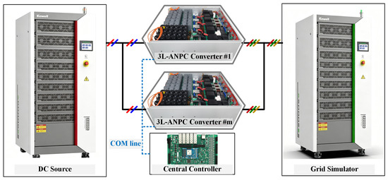
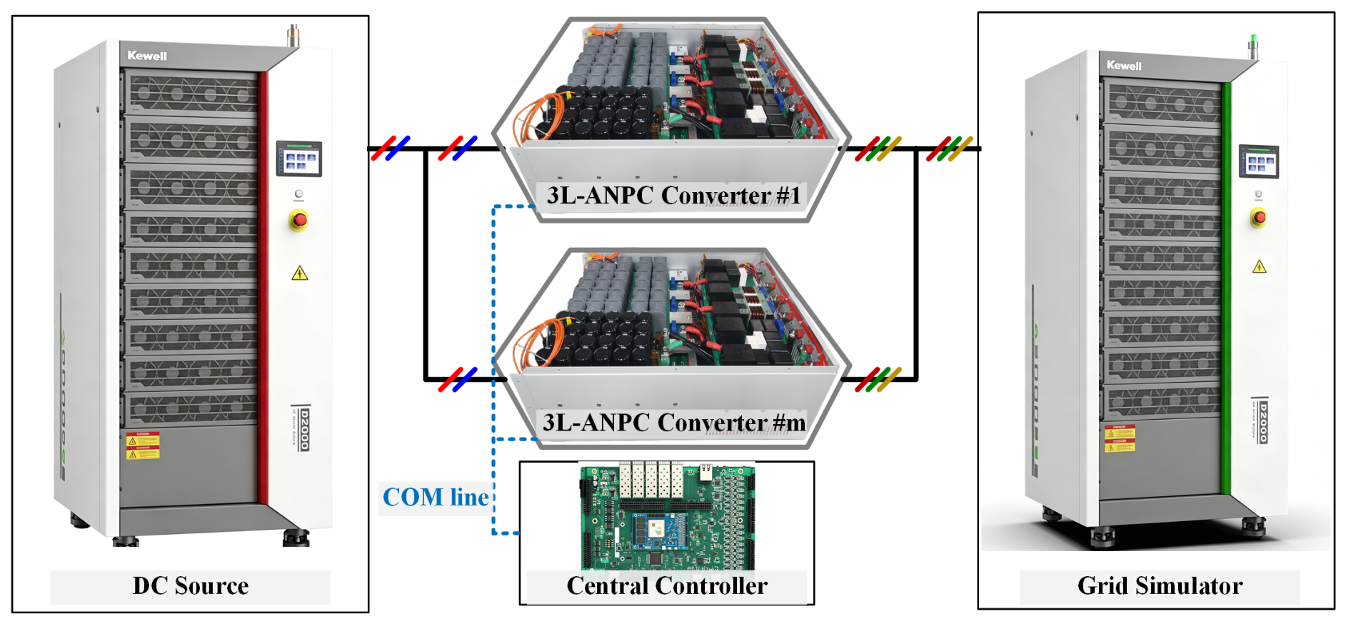
An experimental platform for parallel LCL-type grid-connected converters was established, as shown in Figure 17. Each converter module was connected to the common PCC through an individual LCL filter. Two converters were operated in parallel in the following tests and were assigned identical current references. The sampling instants and switching carriers were synchronized by the central controller, whereas the PCC voltage feedforward and capacitor-voltage feedback signals were generated locally in each module. The main experimental parameters are consistent with those listed in Table 1.
Figure 17.
Experimental platform for the parallel LCL-type grid-connected converter system.
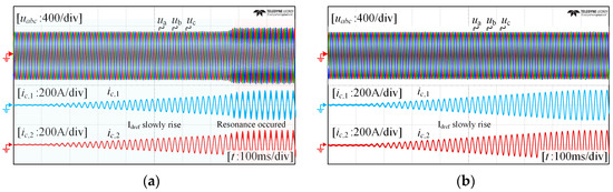
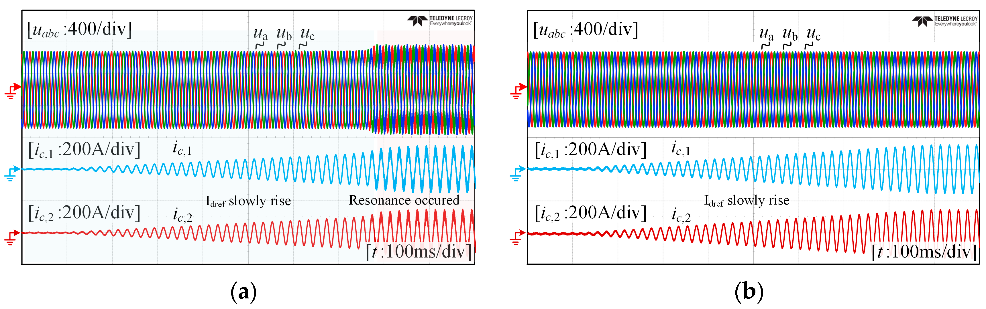
Figure 18 compares the experimental responses of two parallel converters during a gradual increase in the d-axis current reference Idref from 0 to 120 A. Without the additional active-damping paths, stable operation is maintained in the low-current range. However, a sustained high-frequency oscillatory component appears in both converter currents when Idref reaches approximately 110 A, as shown in Figure 18a. These results demonstrate that, as the converter current increases, the resulting reduction in L1 shifts the closed-loop resonance modes toward higher frequencies and weakens the associated damping, thereby exciting the observed high-frequency resonant oscillation. After the proposed coordinated active damping is enabled, no sustained oscillation is observed throughout the investigated wide operating-current range, as shown in Figure 18b. Moreover, the two converter currents exhibit consistent amplitudes and phases, demonstrating balanced current sharing between the parallel converter modules.
Figure 18.
Experimental current-ramp responses of two parallel converters as Idref is increased from 0 to 120 A: (a) without additional active damping; (b) with proposed coordinated active damping.
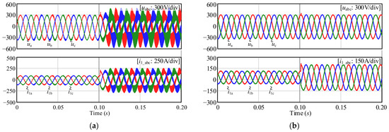
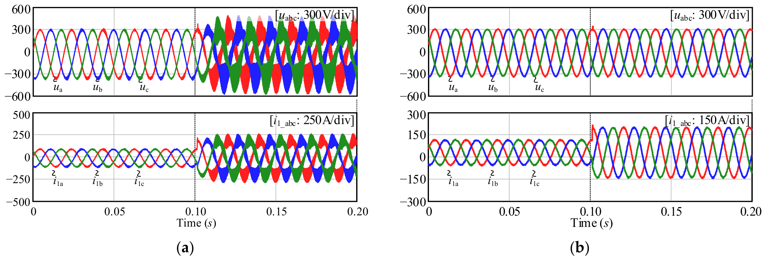
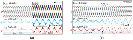
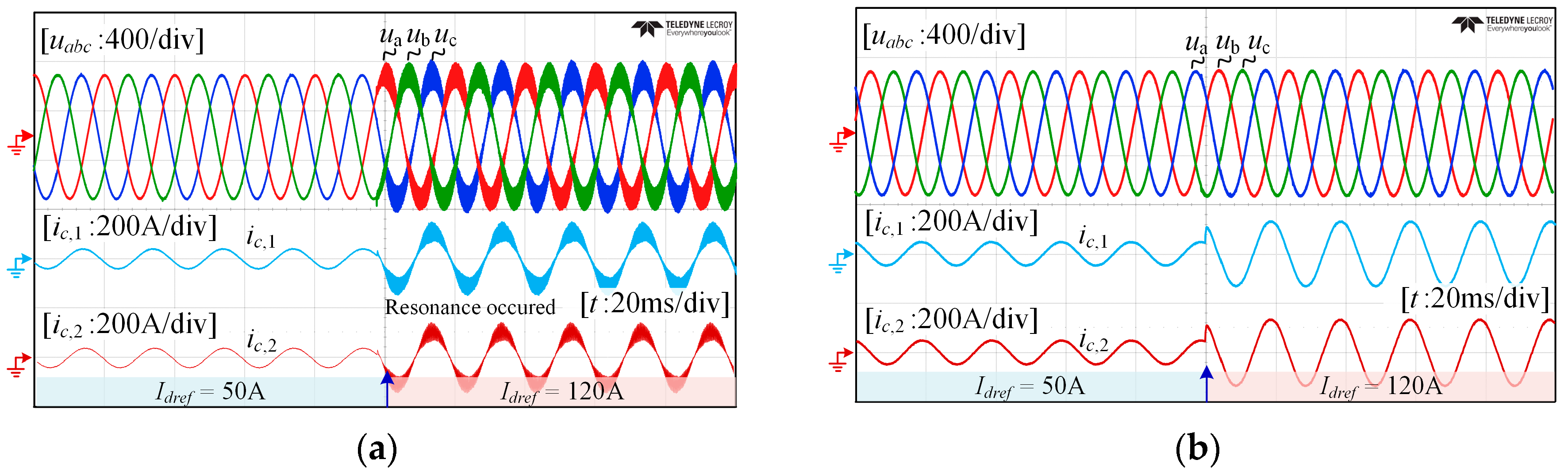
Figure 19 further evaluates the dynamic performance of the parallel converters under a simultaneous d-axis current-reference Idref step from 50 to 120 A. Under conventional current control without active damping, the current-reference step transfers the system from a low-current operating point with a relatively large L1 to a high-current operating point at which L1 is reduced due to magnetic saturation. Consequently, a pronounced high-frequency resonant oscillation is excited in both converter currents, as shown in Figure 19a. In contrast, when the proposed coordinated active damping is enabled, the converter currents track their new reference values without sustained oscillation, while the PCC voltages remain sinusoidal throughout the transient, as shown in Figure 19b. The two converter currents exhibit consistent transient responses and converge to approximately the same steady-state amplitude, indicating balanced sharing of the commanded power increment between the parallel converters.
Figure 19.
Experimental responses of two parallel converters to Idref step from 50 to 120 A: (a) conventional current control without active damping; (b) with proposed coordinated active damping.
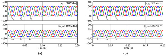
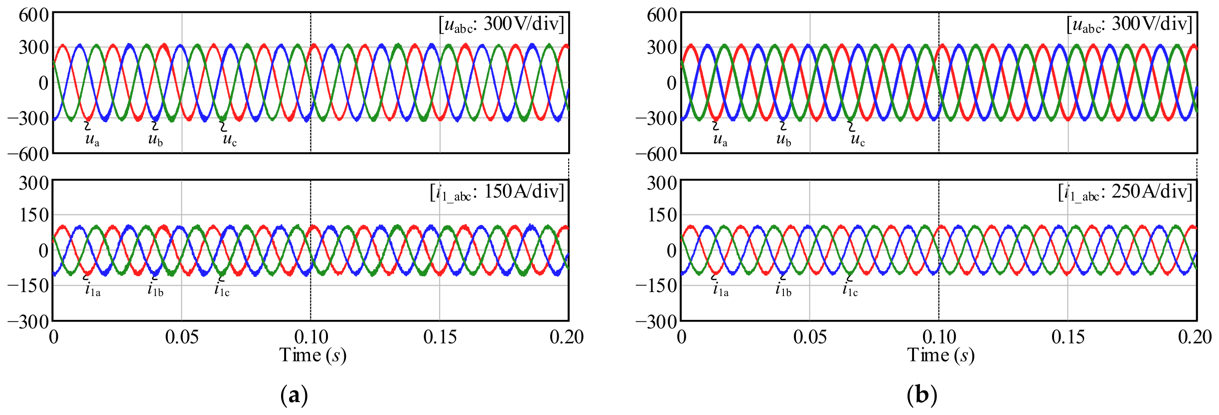
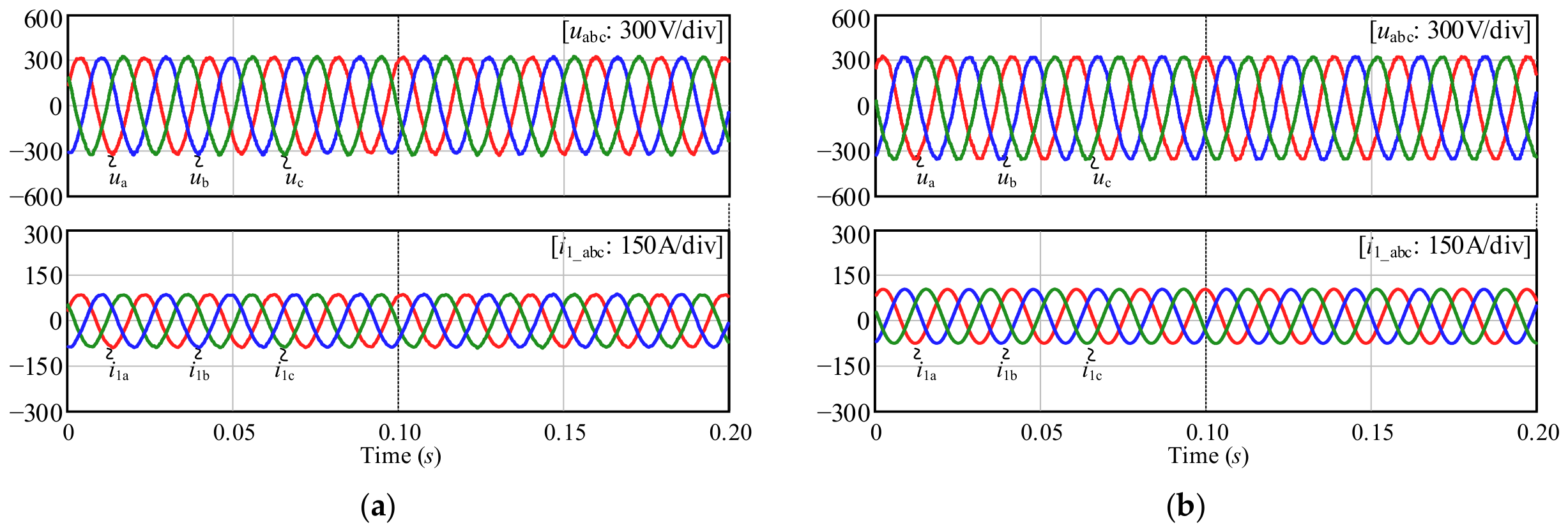
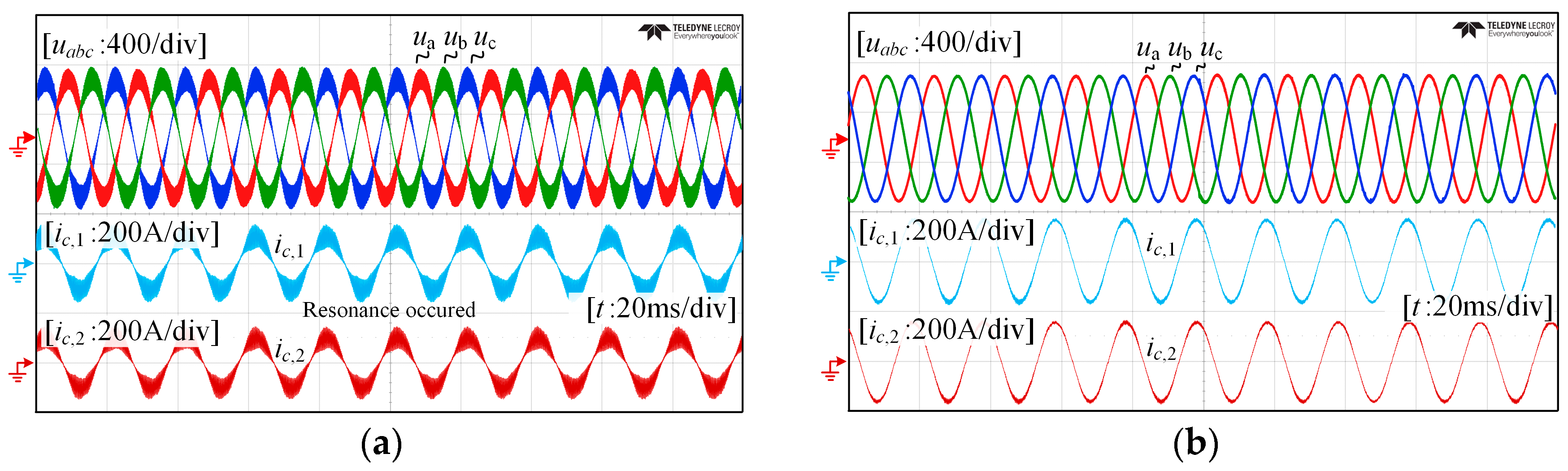
Figure 20 compares the steady-state waveforms at Idref = 120 A. Without the proposed damping, pronounced high-frequency oscillatory components are observed in both converter currents, resulting in considerable current distortion, as shown in Figure 20a. After the coordinated damping paths are enabled, the oscillatory components are effectively suppressed, and nearly sinusoidal converter currents with closely matched amplitudes and phases are obtained, as shown in Figure 20b. The measured grid-current THD is below 3%. These results verify that the fixed damping parameters maintain adequate damping under the combined condition of a reduced inverter-side inductance and a low external grid impedance, without online parameter retuning.
Figure 20.
Steady-state experimental waveforms of two parallel converters at Idref = 120 A: (a) conventional current control without active damping; (b) with proposed coordinated active damping.
5. Conclusions
In this paper, an operating-point-dependent resonance model and a coordinated active-damping method were developed for parallel LCL-type grid-connected converters. The measured current-dependent converter-side inductance was incorporated into a closed-loop Norton equivalent. Inductance reduction increased the internal and parallel-resonance frequencies and the risk of instability, whereas converter number and grid impedance mainly affected the parallel resonance. PCC voltage feedforward and capacitor-voltage feedback were coordinated to regulate the parallel and internal resonances, respectively. For eight converters, grid-current THD decreased from 5.7% to 2.8%, peak current deviation decreased by 23% during a 100–200-A step, and stable operation was maintained as SCR decreased from 10 to 2. Two-converter experiments verified stable transient responses during a 50–120-A step, with THD and power-sharing deviation below 3% and 5%, respectively. The framework applies to balanced, identical converters with individual LCL filters, a PCC, and converter-side current control. The formulation does not account for unequal branch impedances, asynchronous switching, large-signal saturation, or frequency-dependent grid impedance, which require further investigation.
Author Contributions
Conceptualization, C.C.; methodology, C.C.; software, C.C.; validation, C.C., S.G. and J.Z.; formal analysis, C.C.; investigation, Y.C.; resources, C.C.; data curation, C.C.; writing—original draft preparation, C.C.; writing—review and editing, C.C., J.Z., and Y.C.; visualization, X.F.; project administration, C.C. All authors have read and agreed to the published version of the manuscript.
Funding
This research received no external funding.
Data Availability Statement
The data presented in this study are available on request from the corresponding author.
Conflicts of Interest
The authors declare no conflicts of interest.
References
- Dunn, B.; Kamath, H.; Tarascon, J.-M. Electrical energy storage for the grid: A battery of choices. Science 2011, 334, 928–935. [Google Scholar] [CrossRef] [Scilit]
- Luo, X.; Wang, J.; Dooner, M.; Clarke, J. Overview of current development in electrical energy storage technologies and the application potential in power system operation. Appl. Energy 2015, 137, 511–536. [Google Scholar] [CrossRef] [Scilit]
- Pena-Alzola, R.; Roldan-Perez, J.; Bueno, E.J.; Huerta, F.; Campos-Gaona, D.; Liserre, M.; Burt, G.M. Robust active damping in LCL-filter-based medium-voltage parallel grid inverters for wind turbines. IEEE Trans. Power Electron. 2018, 33, 10846–10857. [Google Scholar] [CrossRef] [Scilit]
- He, J.; Li, Y.W.; Bosnjak, D.; Harris, B. Investigation and active damping of multiple resonances in a parallel-inverter-based microgrid. IEEE Trans. Power Electron. 2013, 28, 234–246. [Google Scholar] [CrossRef] [Scilit]
- Lu, M.; Wang, X.; Loh, P.C.; Blaabjerg, F. Resonance interaction of multiparallel grid-connected inverters with LCL filter. IEEE Trans. Power Electron. 2017, 32, 894–899. [Google Scholar] [CrossRef] [Scilit]
- Wang, Y.; Wang, X.; Blaabjerg, F.; Chen, Z. Harmonic resonance assessment of multiple paralleled grid-connected inverters system. In 2017 IEEE 3rd International Future Energy Electronics Conference and ECCE Asia (IFEEC 2017-ECCE Asia); IEEE: New York, NY, USA, 2017; pp. 2070–2075. [Google Scholar]
- Agorreta, J.L.; Borrega, M.; Lopez, J.; Marroyo, L. Modeling and control of N-paralleled grid-connected inverters with LCL filter coupled due to grid impedance in PV plants. IEEE Trans. Power Electron. 2011, 26, 770–785. [Google Scholar] [CrossRef] [Scilit]
- Lu, M.; Yang, Y.; Johnson, B.B.; Blaabjerg, F. An interaction-admittance model for multi-inverter grid-connected systems. IEEE Trans. Power Electron. 2019, 34, 7542–7557. [Google Scholar] [CrossRef] [Scilit]
- Fang, T.; Shen, S.; Jin, Y.; Ruan, X. Robustness investigation of multi-inverter paralleled grid-connected system with LCL-filter based on the grid-impedance allocation mechanism. IEEE Trans. Power Electron. 2021, 36, 14508–14524. [Google Scholar] [CrossRef] [Scilit]
- Liao, S.; Chen, Y.; Wu, W.; Wang, L.; Xu, Q. Closed-loop interconnected model of multi-inverter-paralleled system and its application to impact assessment of interactions on damping characteristics. IEEE Trans. Smart Grid 2023, 14, 41–53. [Google Scholar] [CrossRef] [Scilit]
- Yu, C.; Zhang, X.; Liu, F.; Li, F.; Xu, H.; Wang, Y.; Ni, H. Modeling and resonance analysis of multiparallel inverters system under asynchronous carriers conditions. IEEE Trans. Power Electron. 2017, 32, 3192–3205. [Google Scholar] [CrossRef] [Scilit]
- Cai, Y.; He, Y.; Du, H.; Liu, J. Harmonic state-space modeling and system characteristic analysis of grid-connected inverter parallel-operation system considering asynchronous carriers. IEEE Trans. Power Electron. 2024, 39, 8645–8666. [Google Scholar] [CrossRef] [Scilit]
- Henderson, C.; Egea-Alvarez, A.; Kneuppel, T.; Yang, G.; Xu, L. Grid strength impedance metric: An alternative to SCR for evaluating system strength in converter-dominated systems. IEEE Trans. Power Deliv. 2024, 39, 386–396. [Google Scholar] [CrossRef] [Scilit]
- Hong, L.; Shu, W.; Wang, J.; Mian, R. Harmonic resonance investigation of a multi-inverter grid-connected system using resonance modal analysis. IEEE Trans. Power Deliv. 2019, 34, 63–72. [Google Scholar] [CrossRef] [Scilit]
- Pena-Alzola, R.; Liserre, M.; Blaabjerg, F.; Ordonez, M.; Yang, Y. LCL-filter design for robust active damping in grid-connected converters. IEEE Trans. Ind. Inform. 2014, 10, 2192–2203. [Google Scholar] [CrossRef] [Scilit]
- Pan, D.; Ruan, X.; Bao, C.; Li, W.; Wang, X. Capacitor-current-feedback active damping with reduced computation delay for improving robustness of LCL-type grid-connected inverter. IEEE Trans. Power Electron. 2014, 29, 3414–3427. [Google Scholar] [CrossRef] [Scilit]
- Bao, C.; Ruan, X.; Wang, X.; Li, W.; Pan, D.; Weng, K. Step-by-step controller design for LCL-type grid-connected inverter with capacitor-current-feedback active-damping. IEEE Trans. Power Electron. 2014, 29, 1239–1253. [Google Scholar] [CrossRef] [Scilit]
- Xin, Z.; Loh, P.C.; Wang, X.; Blaabjerg, F.; Tang, Y. Highly accurate derivatives for LCL-filtered grid converter with capacitor voltage active damping. IEEE Trans. Power Electron. 2016, 31, 3612–3625. [Google Scholar] [CrossRef] [Scilit]
- Li, S.; Lin, H. A capacitor-current-feedback positive active damping control strategy for LCL-type grid-connected inverter to achieve high robustness. IEEE Trans. Power Electron. 2022, 37, 6462–6474. [Google Scholar] [CrossRef] [Scilit]
- Wang, X.; Qin, K.; Ruan, X.; Pan, D.; He, Y.; Liu, F. A robust grid-voltage feedforward scheme to improve adaptability of grid-connected inverter to weak grid condition. IEEE Trans. Power Electron. 2021, 36, 2384–2395. [Google Scholar] [CrossRef] [Scilit]
- Chen, Y.; Guerrero, J.M.; Shuai, Z.; Chen, Z.; Zhou, L.; Luo, A. Fast reactive power sharing, circulating current and resonance suppression for parallel inverters using resistive-capacitive output impedance. IEEE Trans. Power Electron. 2016, 31, 5524–5537. [Google Scholar] [CrossRef] [Scilit]
- Liu, J.; Sun, X.; Chen, Z.; Chi, Y.; Song, W.; Zhu, Q.; Wheeler, P. A hybrid multiresonances suppression method for nonsynchronous LCL-type grid-connected inverter clusters under weak grid. IEEE Trans. Power Electron. 2024, 39, 5386–5399. [Google Scholar] [CrossRef] [Scilit]
- Li, M.; Geng, H.; Zhang, X. Distributed coordinated control for stabilization of multi-inverter power plant. IEEE Trans. Ind. Electron. 2023, 70, 12421–12430. [Google Scholar] [CrossRef] [Scilit]
- Fang, J.; Yang, S.; Xie, Z.; Zhang, X.; Chang, L. General parameter tuning method for impedance shaping of the grid-tied inverter. IEEE Trans. Power Electron. 2025, 40, 13459–13473. [Google Scholar] [CrossRef] [Scilit]
- Zhang, J.; Yang, X.; Chen, W.; Zhou, H. Modeling and resonance damping for the CM loop of the MLCL-filtered grid-connected inverter with variable inductors under the weak grid condition. IEEE J. Emerg. Sel. Top. Power Electron. 2022, 10, 310–323. [Google Scholar] [CrossRef] [Scilit]
- Ferrari, M.; Tolbert, L.M.; Piesciorovsky, E.C. Grid forming inverter with increased short-circuit contribution to address inverter-based microgrid protection challenges. IEEE Open J. Ind. Electron. Soc. 2024, 5, 481–500. [Google Scholar] [CrossRef] [Scilit]


Disclaimer/Publisher’s Note: The statements, opinions and data contained in all publications are solely those of the individual author(s) and contributor(s) and not of MDPI and/or the editor(s). MDPI and/or the editor(s) disclaim responsibility for any injury to people or property resulting from any ideas, methods, instructions or products referred to in the content. |
© 2026 by the authors. Licensee MDPI, Basel, Switzerland. This article is an open access article distributed under the terms and conditions of the Creative Commons Attribution (CC BY) license.