


Abstract
This paper proposes a coordinated low-voltage ride-through (LVRT) control framework for three-phase converter-interfaced distributed generation (DG) systems that integrates autocorrection droop control (AcDC) and Adaptive Current-Limited Reactive Priority Control (ACL-RPC). Key limitations of current LVRT control methods are addressed, such as weak and transient performance and adaptability problems due to the presence of post-saturation clipping, indirect current reference shaping, or discrete switching in LVRT current limiting techniques. The AcDC method alters the voltage reference in line with the severity of the voltage dip, while the ACL-RPC method imposes a rigid current limit and constructs the active and reactive current components in a flexible manner. The coordinated method of both approaches even enables the support of voltage with the network, the suppression of current transients, and the seamless control of current with no need for the estimation of network impedance or fault type resolution. The simulations and tests carried out show that the current limit, transient overshoot, and post-fault performance with respect to LVRT methods showed a marked improvement. The results also support the hypothesis that the three-phase converter-interfaced DG systems with the proposed methods offer improved LVRT performance, protection of the converter systems, and enhanced dynamic stability with respect to disturbances from the grid.
1. Introduction
Modern distribution networks are adopting converter-interfaced distributed generation (DG) to improve the flexibility of energy distribution, improve the integration of renewables, and assist local voltage control [1,2,3]. Increased utilization of inverter-based resources, however, causes problems for the stable operation of the system after a disturbance and specifically with voltage sags, which result in transient currents, DC link oscillations, and instability of power for grid-connected converters [3,4,5,6]. These also result in the unwanted disconnection of distributed energy resources, which decreases the reliability of the system.
For stable operation, the LVRT capability has become a standard in the modern grid codes. During a voltage sag caused by a disturbance, switching, or a starting event of a large motor, the DG inverters are required to stay connected and provide reactive current to assist recovery of the voltage at the point of common coupling (PCC) while also providing protection to the converter from overcurrent [4,5,6,7,8,9]. This has become a challenge with the limited current capability of power electronic converters and the strong coupling of the active and reactive power in the case of grid faults.
Current methods of LVRT enhancement include reactive current injection, virtual impedance, droop control, current reference shaping, and magnitude-based current limiting techniques [7,10,11,12]. Although these methods improve fault ride-through capability, they often treat voltage support, current limitation, and post-fault recovery as separate control objectives and thus result in large transient overshoots of the current, a significant reduction in active power, and a low level of flexibility in post-fault recovery in situations of deep voltage sags.
To address these issues, advanced current limiting and control strategies have been developed, such as dual-sequence current control and grid-forming control [13,14,15,16,17,18,19,20]. Wen et al. [13] proposed an optimal current reference generation strategy to improve the coordination of active and reactive current during unbalanced voltage sags. Current limiting strategies for grid-forming converters were investigated by Desai et al. [14] and Baeckeland et al. [15], with an emphasis on converter protection and voltage support capability during faults. Wang and Zhang [16] proposed cooperative voltage and power control to enhance fault ride-through performance, and Arjomandi-Nezhad et al. [17] studied fault recovery and transient stability with current reference limitation. Grid-forming LVRT performance was improved by Deng et al. [18] through reactive power synchronization, by Fernández et al. [19] with dedicated fault ride-through algorithms, and by Sun et al. [20] via enhanced transient stability control. These methods improve fault response, synchronization stability, current control, and reactive power support but can introduce challenges such as high computational complexity, indirect current constraints, and additional coordination requirements. More recent studies have also examined system-level microgrid resilience beyond converter-level LVRT control. Correia et al. [21] have presented a resilient microgrid control strategy for transitions between grid-connected and islanded modes through adaptive resource management. However, the system-level resilience strategies are mainly concerned with the supervisory operation, while the current limitation and reactive current prioritization at the converter level during voltage sags are still challenging. Therefore, an integrated LVRT control strategy is still needed to realize effective voltage support, strict current limiting, and smooth active/reactive power transfer.
It is worth noting that the proposed AcDC-ACL-RPC framework is developed for grid-connected distributed generation systems. The present work deals with LVRT improvement during grid events. Islanded microgrid operation and grid-connected/islanded mode transition require additional voltage frequency regulation and synchronizing mechanisms that are out of scope of this work. To resolve the challenges mentioned above, the presented methodology integrates AcDC and ACL-RPC in three-phase, converter-based, distributed generation systems. The AcDC mechanism adaptively changes the voltage reference based on the severity of the voltage sag and the system’s operating conditions. The ACL-RPC mechanism applies a strict current boundary for the inverter through the real-time flexible allocation of active and reactive current. The coordinated methodology provides a smooth transition between the voltage restoration mode and the reactive current limiting mode.
The main contributions of this work are as follows: (i) AcDC–ACL-RPC control framework integration for LVRT in DG systems; (ii) a sag-adaptive reactive allocation control law with a strict current boundary of the inverter; (iii) a practical boundary for the operation of the system at a voltage of 0.78 p.u. with a transition between voltage restoration and reactive current control; and (iv) improved simulation and DSP-based experimental results for system protection and compliance of the system to LVRT under multiple voltage sag conditions.
2. System Configuration and Control Methodology
This section describes the control and modeling techniques used to analyze the behavior of three-phase distributed generation systems during voltage sags and formalize the voltage sag and LVRT control requirements, which will serve as design constraints for the proposed control techniques. Based on these, the designs of AcDC and ACL-RPC are explained, along with the simulation configurations and corresponding experimental validation.
2.1. System Description and Modeling
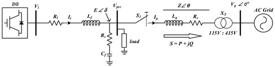
The power circuit diagram of a grid-connected DG unit is presented in Figure 1. This unit has the capability of serving a local load under normal operating conditions and in the event of a grid fault. The system consists of a three-phase voltage source inverter (VSI), an output filter, a local load at the PCC with a grid, and a step-up transformer connecting the PCC with the off-string distribution network. The inverter has a cascaded control arrangement with power, voltage, and current control loops, which enables the inverter system to reach power equilibrium with the grid and regulate the PCC voltage to a desired value.
Figure 1.
System architecture.
The VSI generates a pulse width-modulated three-phase voltage, (the unfiltered output of the inverter containing switching harmonics). An output filter consists of series inductance , parasitic resistance (which is in series with the inductor), and a shunt capacitor with resistance . It acts as a high-frequency shunt to ground and produces a voltage at the PCC equal to (the filtered inverter voltage). In order for the filtered inverter voltage, , to meet the operational requirements of the inverter in the grid-connected mode, it must be both synchronized and phase-aligned to the grid voltage, . In a phase-locked loop, this is done so that in a steady-state condition, δ is as close to 0 as possible.
After steady state and synchronization are achieved, the grid switch is turned on to create a grid-connected configuration, allowing the DG unit to perform a two-way power transaction with the primary grid via the transformer and impedance of the series connection, . The PCC can be associated with the voltage, . This is the point of the convergence of the DG, the local load, and the grid. This point also defines voltage sags and determines the LVRT in the analysis. For the control design dynamic model, all three-phase components in the model are aligned to the synchronous dq frame with , and the primary control for the inverter is the current through the filter inductor.
Based on the power model of the distributed generator of the grid-connected inverter shown in Figure 1, active () and reactive power () are defined, respectively, in Equations (1)–(4).
Considering δ to be a very small or almost zero value means cos δ is approximately equal to 1 and sin δ is approximately equal to δ. In this way
The decoupling input/output variation is affected by the impedance angle . When the impedance is inductive and equals rad, it can be concluded that and are also roughly proportional in this case as well.
2.2. Voltage Sag and LVRT Requirements
LVRT requirements describe a voltage time domain where a DG unit is to be maintained connected during a grid disturbance. In this study, the LVRT profile is considered as the design and assessment benchmark of the low-power DG prototype. While the laboratory-scale system is smaller than the full-scale DG systems, the LVRT profile, as used, allows the controller to be assessed consistently for moderate and severe voltage sags.
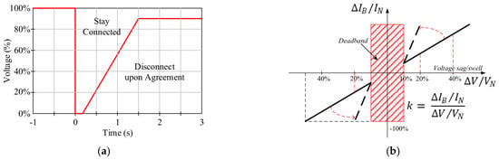
The LVRT curve, as shown in Figure 2, defines the sag depth and the boundary of the sag duration for which a DG unit shall remain connected during the specified voltage sag. During LVRT, the controller goal is to maintain the unit connected, inject necessary reactive current to assist in the recovery of the system voltage, and keep the inverter current to the rated level to avoid the operational stress of the inverter [5,19,20].
Figure 2.
Requirement for a German grid code: (a) LVRT curve (VDE-AR-N 4120); (b) region for reactive power injection.
The unconstrained reference for the q-axis current is given by:
where
- is the unconstrained reactive current reference;
- is the reactive current gain;
- is the measured PCC voltage during the sag;
- is the nominal PCC voltage.
In the proposed ACL-RPC, this reference is not used in this manner. Instead, it will go through a current limiting and active/reactive power balancing process, ensuring safe inverter operation while providing the necessary voltage support. Thus, the LVRT profile and reactive current reference have been adopted as benchmarks to pass or fail each of the simulated or tested sag events as well as describe the performance of the AcDC-ACL-RPC in providing support to the PCC voltage against the converter current limit.
2.3. Autocorrection Droop Control (AcDC) Design
The objectives of the AcDC strategy include sustaining a reliable voltage drop reference during sag events and enhancing the effectiveness of the dynamic response of Control of Voltage and Reactive Power () droop control strategies. It also concerns itself with the responsiveness of DG to system disturbances and the process of restoring the system voltage back to the normal operating conditions of the grid following a disturbance [5,22,23,24].
The AcDC algorithm is implemented as a sequential voltage support routine during voltage sag operation. First, the controller continuously measures the PCC voltage , active power , and reactive power from the inverter output. A voltage sag is detected when falls below the predefined threshold voltage . Once a sag is detected, the sag depth is calculated based on the deviation between the nominal PCC voltage and the measured PCC voltage. This sag depth information is then used to update the d-axis and q-axis voltage references, and , so that the inverter can increase voltage support according to the severity of the disturbance. At the same time, the droop coefficients are adjusted dynamically using the instantaneous power condition, allowing the controller to modify the voltage–power relationship during the fault. The updated voltage references are finally sent to the inner voltage and current control loops, which generate the required inverter current commands for PCC voltage restoration and stable post-fault recovery.
2.3.1. Droop Control and Autocorrection Term
Droop control enables inverters to regulate their output voltage while coordinating and injection in a decentralized manner. In droop control, a quasi-linear relationship is established between and the bus voltage , as well as between and , allowing the inverter to autonomously adjust its output to support the grid under varying load or fault conditions [7,13,19,20,25]. Incorporating an autocorrection term further enhances system stability by dynamically adjusting the droop slope or reference, mitigating voltage deviations, and improving the response during voltage sags or transient events [7,13]. We can mathematically describe this linear dependency as follows:
where
- are the d-axis and q-axis voltage references;
- are the nominal dq-axis voltage references;
- are droop coefficients;
- are the instantaneous active and reactive powers.
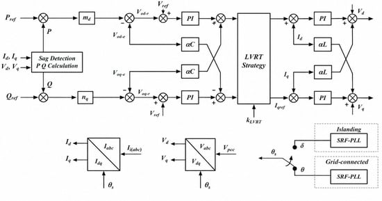
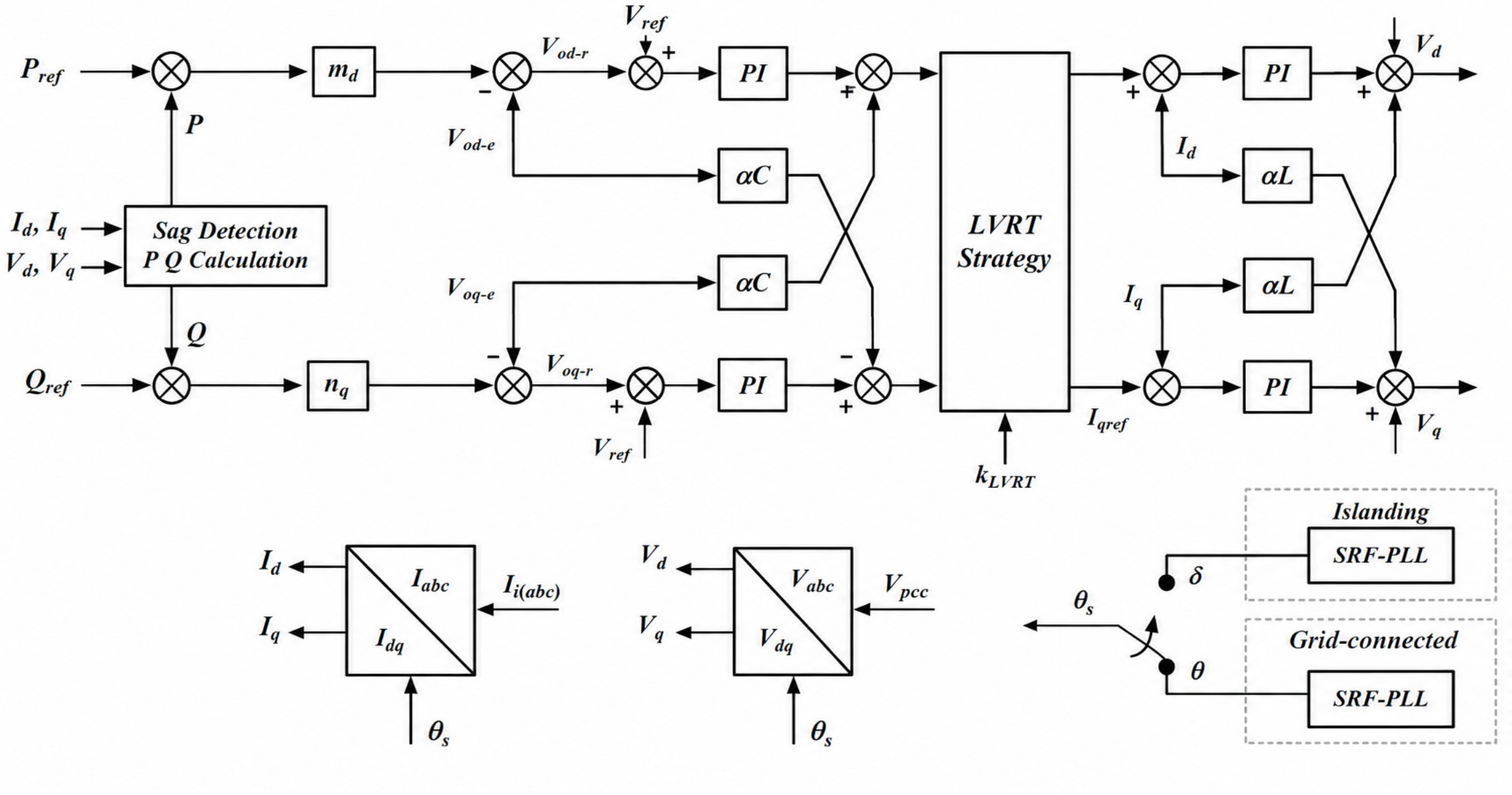
The term autocorrection was introduced, referring to adjusting nominal voltage references to account for the droop in effective power. It provides better voltage regulation during voltage sags using and , with local parameter relations that include instantaneous power. Figure 3 outlines the droop control autocorrection block that works with the LVRT strategy during the detection of sag and during the estimation of active and reactive power.
Figure 3.
Control block diagram of the AcDC and LVRT strategies.
2.3.2. Dynamic Adjustment of Voltage References
The nominal voltage references are dynamically scaled based on instantaneous apparent power :
where
- are pre-disturbance dq-axis voltage references;
- is a constant;
- is the adaptive scaling factor.
This scaling factor allows the voltage references to adapt to changing loads and ensures the inverter can detect and synchronize to changes in power output. The algorithm can dynamically adjust the droop curve as a function of active and reactive power, thereby improving the system and inverter voltage recovery time during grid faults.
2.3.3. Modified Droop Control Based on Voltage Sag Depth
The droop curve can be adjusted further during voltage sags to increase the system’s response time. The modified voltage references are defined as:
where
and are the per-unit active and reactive powers, respectively.
Integrating this modification allows the voltage references to be defined as a function of the voltage sag and ensures the system can respond to a shift in the grid voltage and maintain a certain level of power quality. The droop coefficients and are also adjusted as a function of the sag depth to increase voltage support during disturbances.
2.3.4. Voltage Error and Control Adjustment
The voltage error that occurs during a sag event is expressed as:
where
- is the reference voltage of the inverter.
- and are the voltage errors in terms of d-axis and q-axis, respectively.
In steady state, the voltage error should approach zero:
It shows that the control system adjusts the inverter output to compensate for the voltage sag error, enabling rapid, precise recovery from the sag. Therefore, the droop control system enables the inverter to manage voltage disturbances effectively and assists in grid voltage recovery.
2.3.5. Steady-State Voltage Recovery
In steady-state conditions, the inverter’s output voltages for the d-axis and q-axis can be written as:
This configuration effectively controls the inverter’s output to maintain the desired d-axis and q-axis voltage, which confirms that the inverter is (1) supporting the grid’s voltage and (2) helping the inverter to maintain continuous voltage sag during the event.
The AcDC strategy provides dynamic adjustment of the droop coefficients based on active and reactive power. The inverter’s voltage references are continually recalibrated to deliver voltage support during the lag efficiency voltage. This strategy also helps minimize voltage disturbances, keeps the sag duration within the maximum acceptable limits, ensures compliance with LVRT standards, and provides the grid with fault recovery system capability. The key control technique of this strategy is to maintain improvements in the system’s stability and performance by balancing the reactive power injected and the active power delivered.
2.4. Comparison Techniques of Current Limiting Implementation on LVRT Strategy
Current limiting is required for LVRT operation of grid-connected converter-interfaced distributed generating systems. In case of grid voltage sags, the inverter current can quickly exceed its rated value due to abrupt variations in the PCC voltage, which can lead to semiconductor stress and possible converter tripping. Thus, several LVRT current limiting solutions have been proposed to assure safe operation while retaining grid support capabilities.
Online current limiting systems normally apply current limitation only when the measured current is over its threshold. These approaches are simple and effective for protection, but they cannot completely suppress the transient inrush current during the fault inception stage. They are usually utilized in the grid-feeding converters [26]. The grid-compliant current reference generation methods can enhance the LVRT performance by tuning the d–q current references, depending on the voltage sag depth and unbalance conditions. However, this limitation is achieved indirectly by reference shaping, which does not guarantee strong boundary enforcement under severe fault situations [27].
Advanced dual-sequence current control systems improve reactive power supply by controlling the positive and negative sequence components during asymmetrical voltage sags. These methods enhance the voltage support capabilities but suffer from higher computational complexity and transient current overshoot during quick fault transition [28]. Furthermore, two-stage current limiting solutions are proposed to improve the system recovery by decoupling the fault and post-fault operation modes. However, the main focus is on post-fault synchronization stability rather than transient suppression at the fault initiation [29].
To clearly show the differences of the existing methodologies, the representative LVRT current limiting strategies are summarized in Table 1 from aspects of transient performance, voltage support capability, current limitation efficacy, and operational flexibility.
Table 1.
Comparative evaluation of LVRT current limiting strategies and the proposed AcDC and ACL-RPC method under voltage sag conditions.
2.5. Adaptive Current-Limited Reactive Priority Control (ACL-RPC)
ACL-RPC is intended to optimize inverter deployment during LVRT events. Control maintains active voltage reactive current injection, balancing grid robustness concerns within the inverter’s operational limit. One of the key advantages of the proposed adaptive current limitation is its ability to allocate the inverter’s total current between reactive and active components based on the inverter’s operational current range and the extent of the controlled voltage sag.
The proposed AcDC-ACL-RPC framework is developed in a grid-following inverter architecture. The proposed method differs from grid-forming control strategies that define independent voltage and frequency references by relying on the grid-synchronized system and enhancing the LVRT performance via adaptive voltage support control and current-constrained active/reactive power management. The proposed method thus complements existing grid-forming approaches by improving the fault response capability of grid-following distributed generation systems without modifying the basic control structure.
AcDC and ACL-RPC are not independent and parallel but coordinated with a hierarchical control structure. The AcDC strategy is the voltage support control layer that adjusts the voltage references and droop characteristics according to the severity of voltage sag. The current demand resulting from this is then handled by ACL-RPC, which serves as a current-management layer to keep the inverter within its allowable current limit. In case of severe voltage sag conditions, ACL-RPC modifies the active and reactive current sharing towards reactive current injection with a reduced active current component when required. Thus, AcDC specifies the required voltage support response, and ACL-RPC guarantees the feasible implementation by considering the converter current limitations.
The strategy calculates the reactive current reference based on the grid voltage sag and the maximum limit (). The initial reactive current reference is defined as:
where
- is an adaptive gain factor;
- is the grid voltage in per unit;
- is the nominal current of the inverter;
- is the maximum allowable current.
Next, the active current reference is calculated based on the remaining current capacity:
where is the power output of the photovoltaic (PV) system, and is the grid voltage magnitude. The total injected current is the vector sum of and :
To ensure the inverter operates within its safe limits, the algorithm also includes current limit enforcement, scaling the currents if the total exceeds the current capacity .
When the reactive current reference is prioritized during a voltage sag, the available capacity for the active current component decreases. Consequently, the AC-side active power may become lower than the DC-side input power, causing energy accumulation in the DC link capacitor. The corresponding DC link dynamics are represented by
To mitigate DC link overvoltage, the proposed controller incorporates a supervisory active power curtailment function. When the measured DC link voltage exceeds its reference value, the available source-power reference is reduced according to
Under the balanced three-phase voltage sag conditions considered in this study, negative sequence-induced double-frequency power oscillations are not present. However, an average DC link power imbalance may still arise during active current limitation. The present experimental assessment focuses on the AC-side control response; therefore, detailed DC link voltage validation remains outside the demonstrated scope.
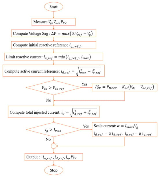
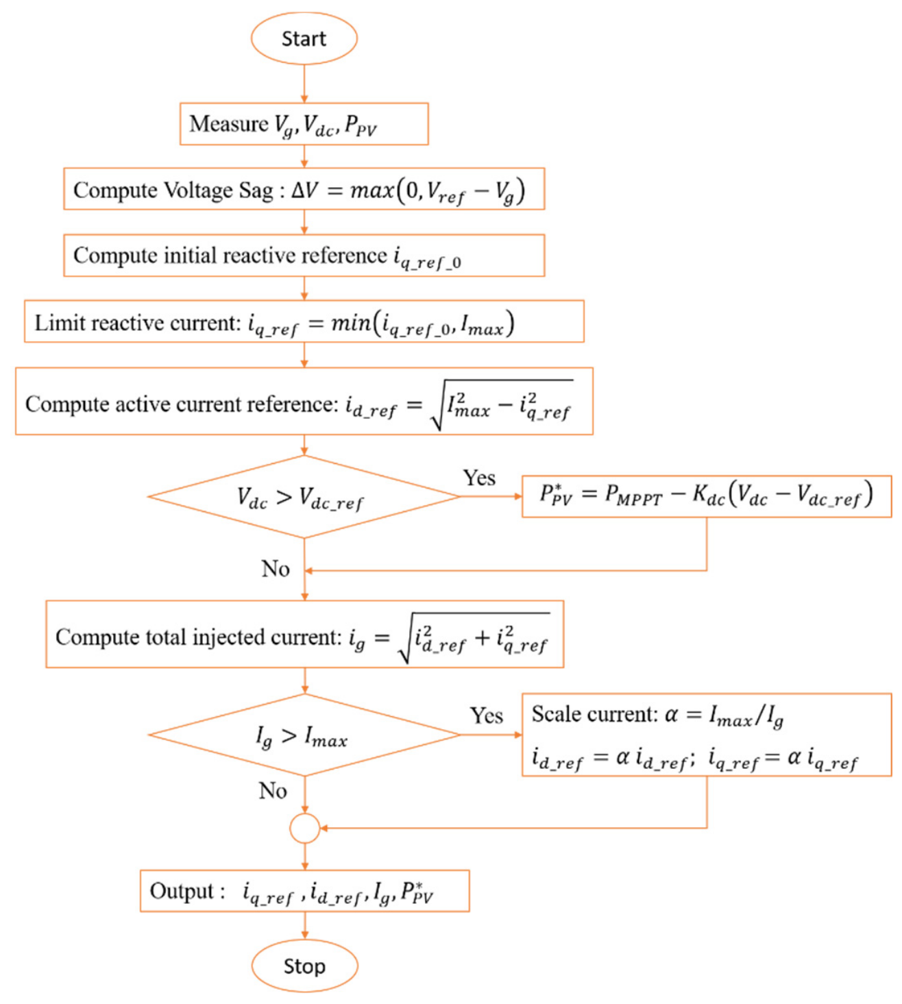
Figure 4 illustrates the flow of operations of the proposed adaptive LVRT control system, starting with voltage sag detection and sequential control operations for current allocation. The flow diagram illustrates the control process in detail, while the control limit is back-scaled during the voltage sag.
Figure 4.
Flowchart diagram of the ACL-RPC algorithm.
2.6. Implementation Details and Test Scenarios
The proposed AcDC-ACL-RPC control strategies were evaluated using both PSIM time domain simulation and laboratory testing. In particular, the behavior of the controller was examined for different sag depths in the simulation. The hardware platform confirmed the real-time capability of the control implementation on the TMS320F28335 DSP. Moreover, the joint method agrees with the recent LVRT studies [13] describing the control of the voltage support, the limitation of the converter current, and the post-fault recovery, with both simulation and experimental support.
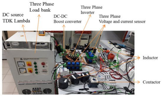
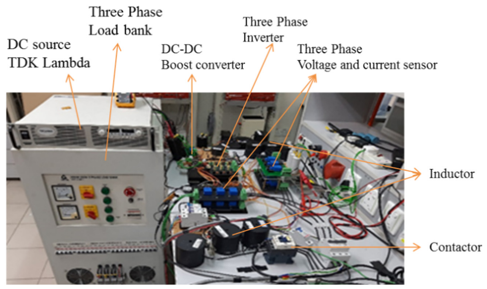
The arrangement of the experiment is illustrated in Figure 5. Specifically, it consists of a DC power supply, a DC-DC boost converter, a three-phase inverter, a three-phase load bank, inductors, contactors, and a set of current and voltage sensors. In this configuration, the design aims to recreate scenarios of voltage sags and to measure responses of the inverter current, PCC voltage, and the active and reactive power. Consequently, current and voltage measurements of this design provide feedback for the AcDC and ACL-RPC control design.
Figure 5.
Experimental setup for the proposed DG.
In this study, the transformer was considered as the grid interface component between the inverter and the PCC under established operating conditions. The validation aimed to investigate the inverter-side control performance during voltage sag events, considering PCC voltage support, reactive current prioritization, and converter current limit handling. Transformer nonlinear effects, such as core saturation and energization inrush currents, were not considered since the study did not involve transformer energization or switching transient events. Detailed transformer magnetic modeling will be included in future studies to assess the effect of saturation on LVRT performance.
The experimental platform is a small-scale DG system designed for the validation of the proposed control methodology in a controlled laboratory environment. Although the voltage and power ratings are smaller than those of practical utility-scale DG units, the proposed control framework, which is based on normalized current allocation, droop adjustment, and converter current constraints, is scalable to higher power systems with proper parameter tuning. However, for practical implementation in larger DG systems, other factors such as the thermal limits of converters, filter design, impedance characteristics of the grid, and protection coordination need to be considered.
The main parameters of the power stage and the control system, used in both the simulation and the hardware tests, are provided in Table 2. These parameters set the control system in the simulation and hardware tests, and they determine the rated voltage, the filter components, the switching frequency, the droop coefficients, and the transformer ratio. As a result, they ensure consistency between simulation and experimental validation environments. The following scenarios were implemented for performance evaluation:
Table 2.
Proposed system parameters.
- Normal operation: The DG unit has been set to a nominal voltage level and is providing a given amount of active power. This is to set a pre-fault baseline.
- Voltage sag events: Sag depths of 0.86, 0.78, 0.70, 0.60, and 0.17 p.u. were simulated, while a 0.77 p.u. sag was applied in hardware. The simulated sag duration was 50–100 ms, while the hardware duration was approximately 400 ms to account for real-time limitations. The difference in sag duration between simulation and hardware testing was chosen according to the objective and constraints of each validation platform. The simulation cases were designed to evaluate the transient control response under controlled fault duration, while the longer hardware sag duration was adopted to provide sufficient observation time for real-time measurement and controller verification. Consequently, the simulation and experimental results are interpreted based on the consistency of control behavior such as voltage support response, current limitation, and reactive current prioritization, not by direct comparison of identical transient waveforms.
- Load variations: Both resistive and RLC loads were applied to evaluate controller robustness under different local–load conditions.
- LVRT assessment: Minimum PCC voltage, recovery time, current overshoot, active/reactive power response, and current limit compliance were evaluated against the adopted LVRT profile. These indicators follow commonly reported metrics in LVRT studies.
Overall, these scenarios allow the AcDC and ACL-RPC strategies to be tested under normal operation, moderate sag, deep sag, ultra-deep sag, and post-fault recovery conditions, providing a comprehensive evaluation of the proposed control framework.
3. Results
This section describes how the autocorrection droop control and ACL-RPC strategies are tested for a three-phase DG under representative grid voltage sag conditions. It seeks to demonstrate the improvements in LVRT capability, response transience, and power conversion efficiency, in line with modern grid code requirements.
3.1. Autocorrection Droop Control Performance in Different Loads Under Three-Phase Voltage Sags
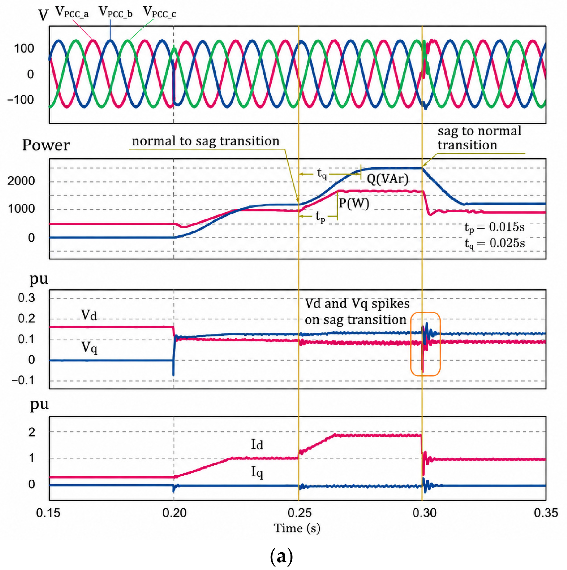
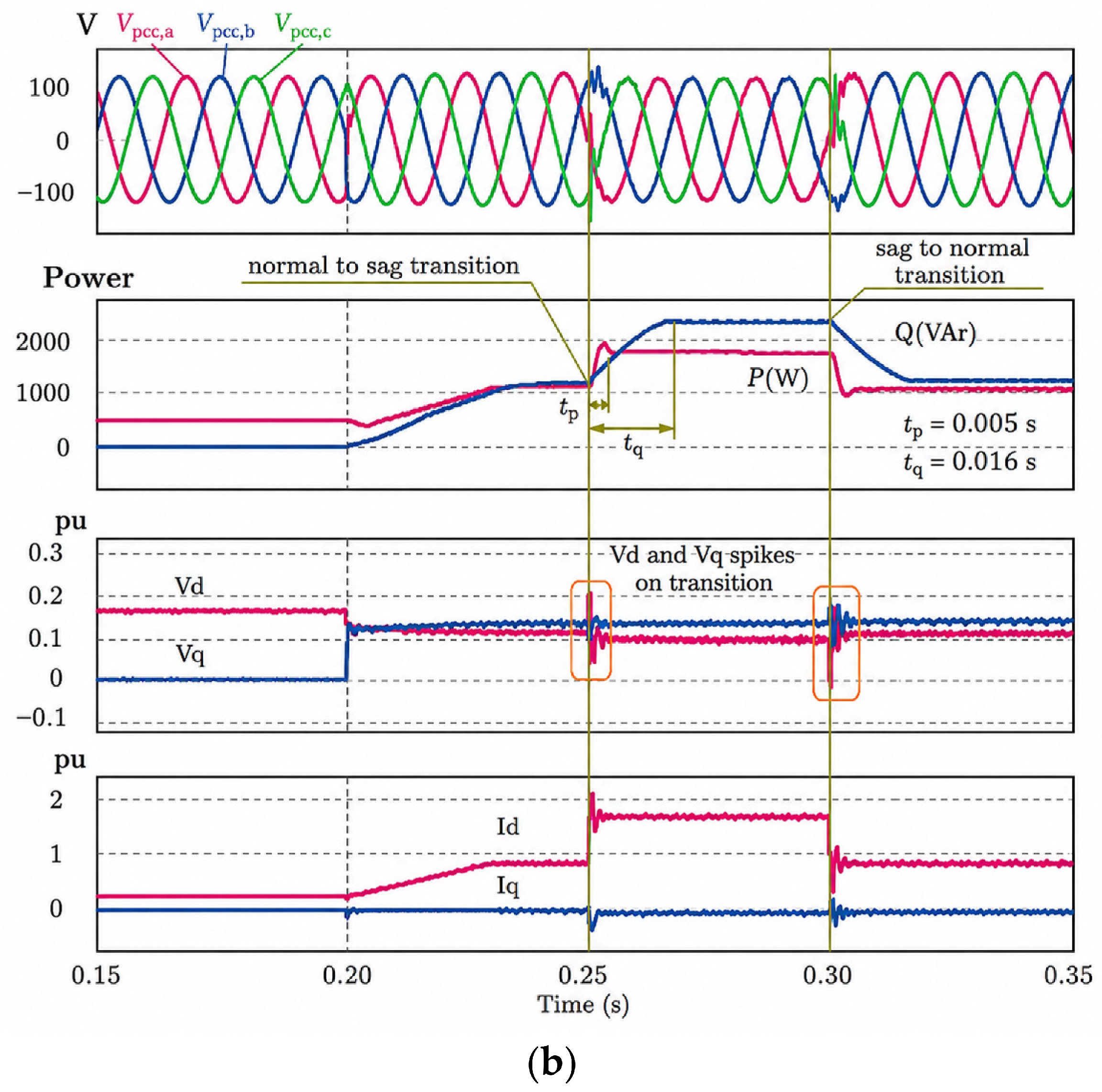
This subsection analyzes the dynamic performance of the AcDC scheme against the conventional droop control (CDC) scheme under a variety of local loads of 82 W, 55 W, and 16.5 W, as well as resistive, inductive, and capacitive loads (RLC). The ability of the control strategies to maintain the system’s power delivery and support the PCC voltage under a three-phase short circuit is examined. For the 82 W case shown in Figure 6, both controllers successfully restore the PCC voltage and supply the local load when the grid voltage drops to the CDC. However, the CDC shows a pronounced drop in the active current and the active component voltage, leading to a current voltage drop of approximately 60 ms. Conversely, the proposed AcDC can maintain active and reactive power during actuator disruption.
Figure 6.
Comparison between schemes to handle drop voltage under a load of 82Ω: (a) conventional droop control; (b) autocorrection droop control.
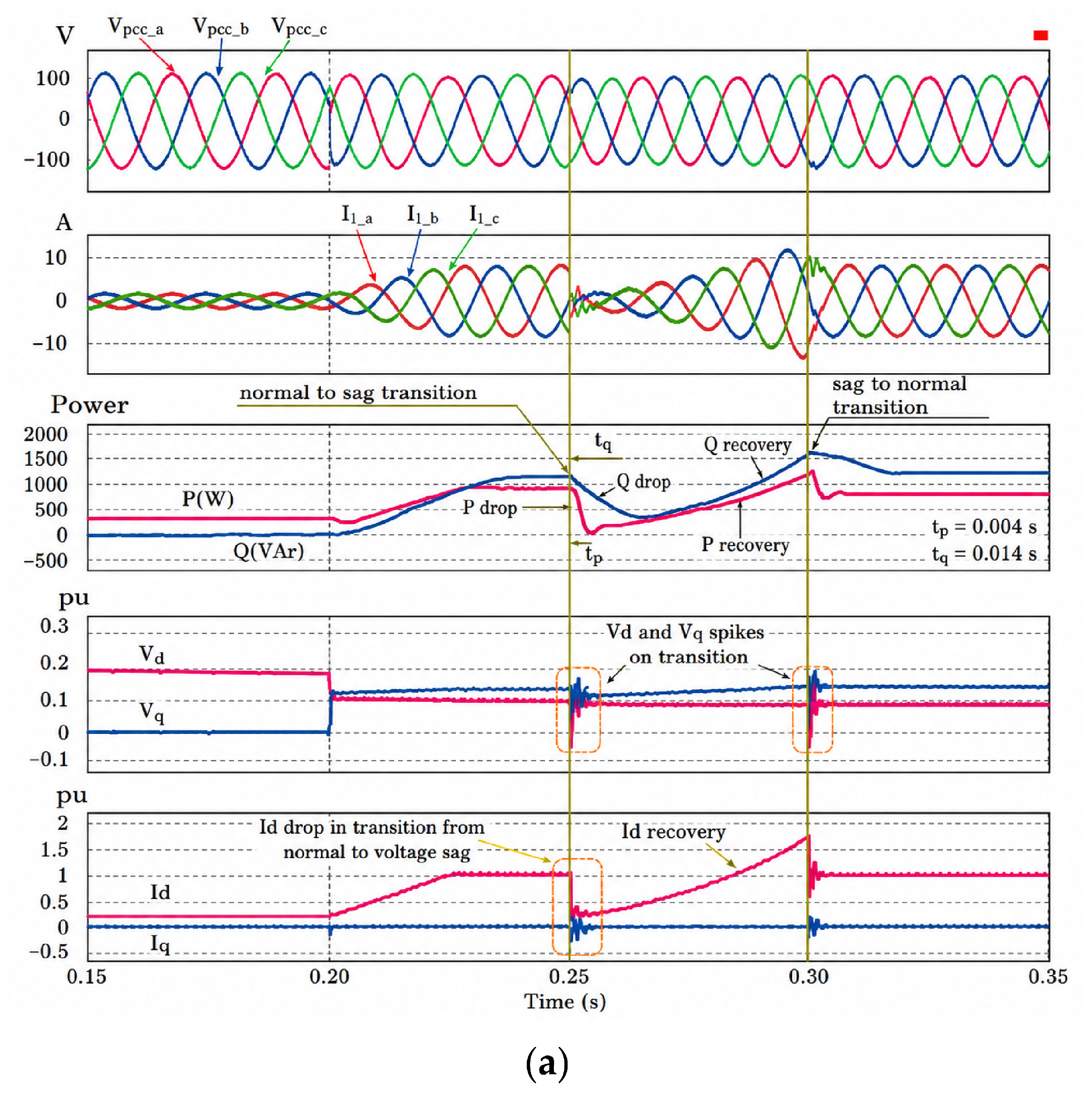
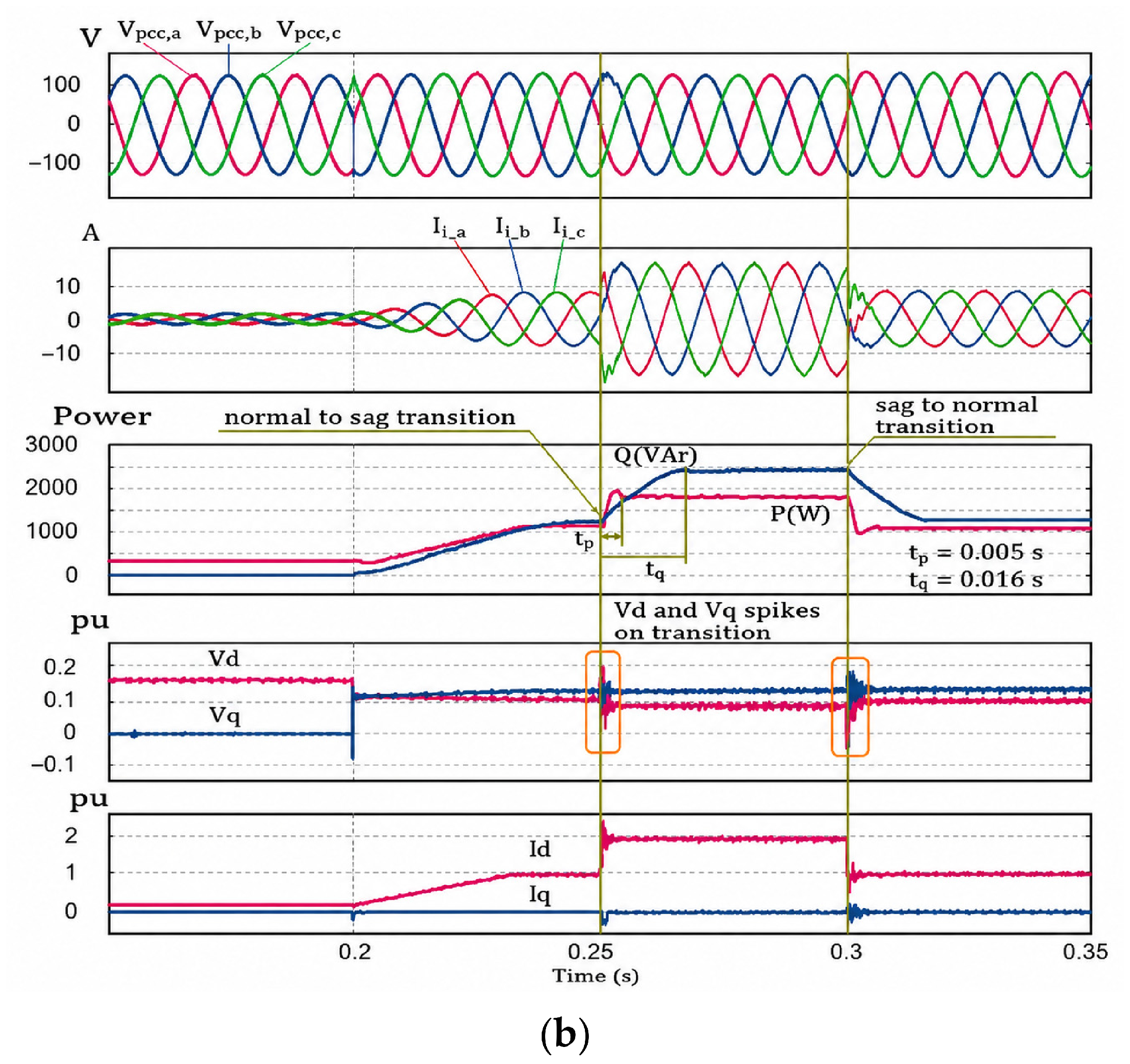
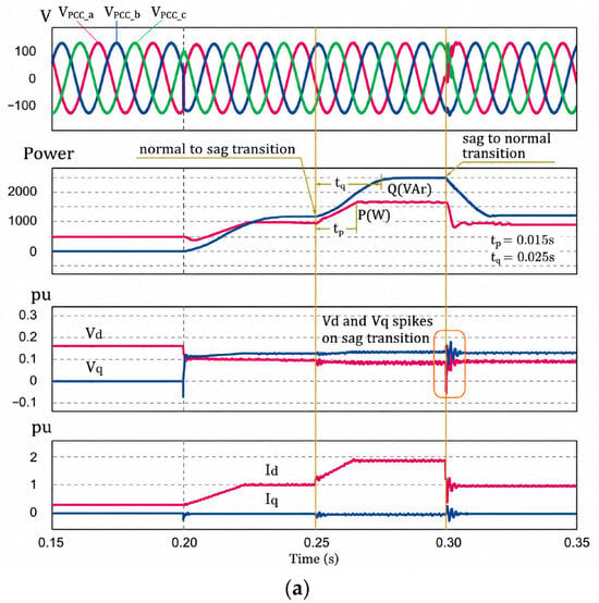
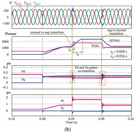
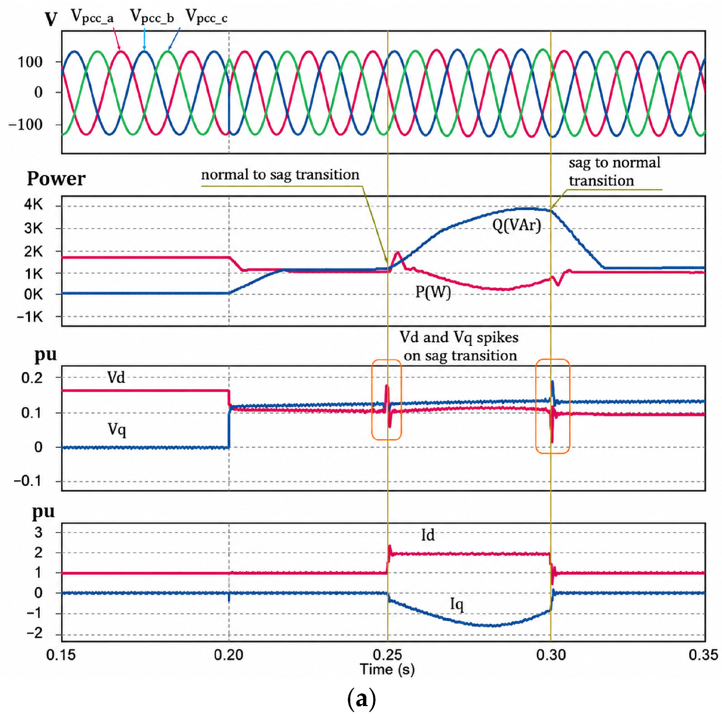
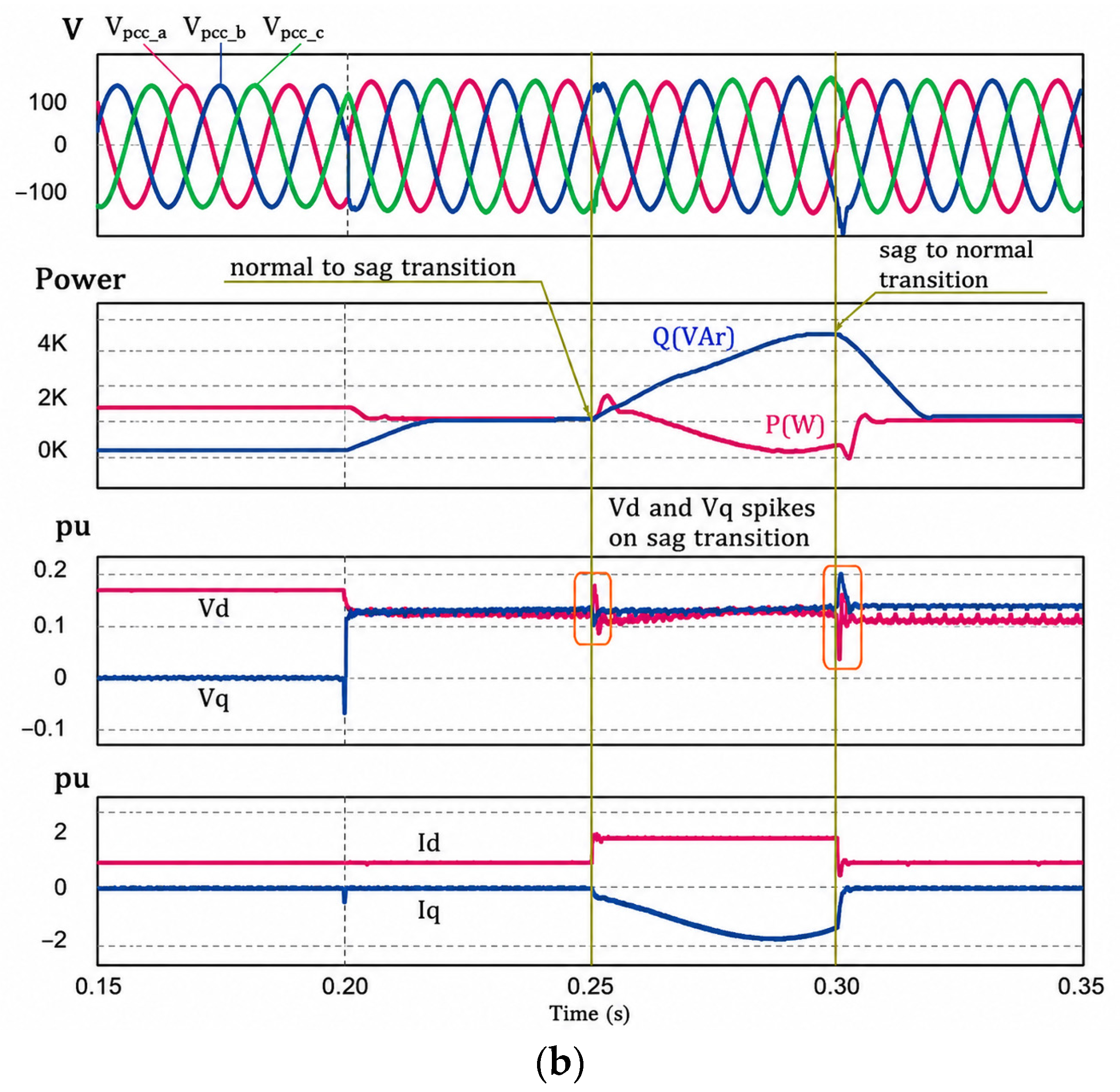
With the 55 W local load, as shown in Figure 7, both traditional droop control and the proposed AcDC control support the load and ride through the grid voltage dip. However, the conventional droop control scheme is slower, requiring about 15 ms and 25 ms for the active and reactive power, respectively, to reach their steady state after the sag. The proposed scheme is shown to recover the active and reactive power in about 5 ms and 16 ms, respectively. It shows that the proposed control scheme improves the recovery of the power variables. While the proposed scheme improves the dynamic behavior of the control system, it also increases small-amplitude spikes in the dq-frame voltage and current due to the aggressive nature of the control. However, they are not at a level that would compromise the control system’s stability. In the case of the 16.5 W load shown in Figure 8, both control approaches successfully cope with the grid voltage dip, and the inverter is seen injecting reactive power rather than active power to the grid during the dip. However, the proposed AcDC scheme is shown to improve the post-fault power profiles when compared to the traditional droop control scheme.
Figure 7.
Comparison between schemes to handle drop voltage under a load of 55 Ω: (a) conventional droop control; (b) autocorrection droop control.
Figure 8.
Comparison between schemes to handle drop voltage under a load of 16.5 Ω: (a) conventional droop control; (b) autocorrection droop control.
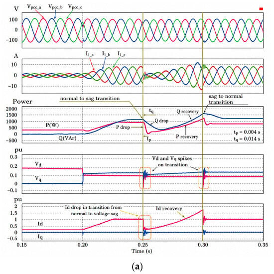
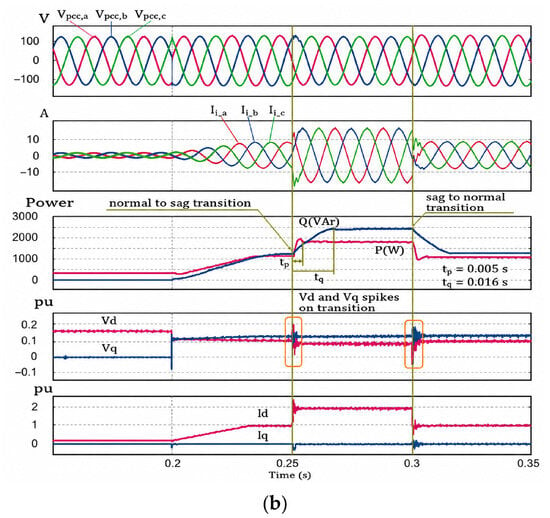
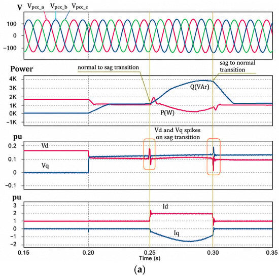
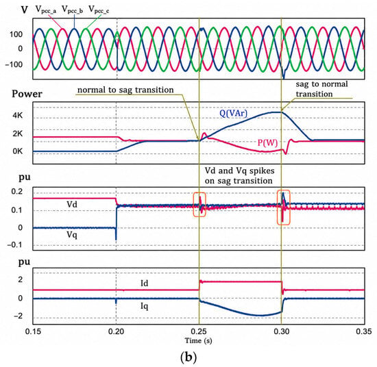
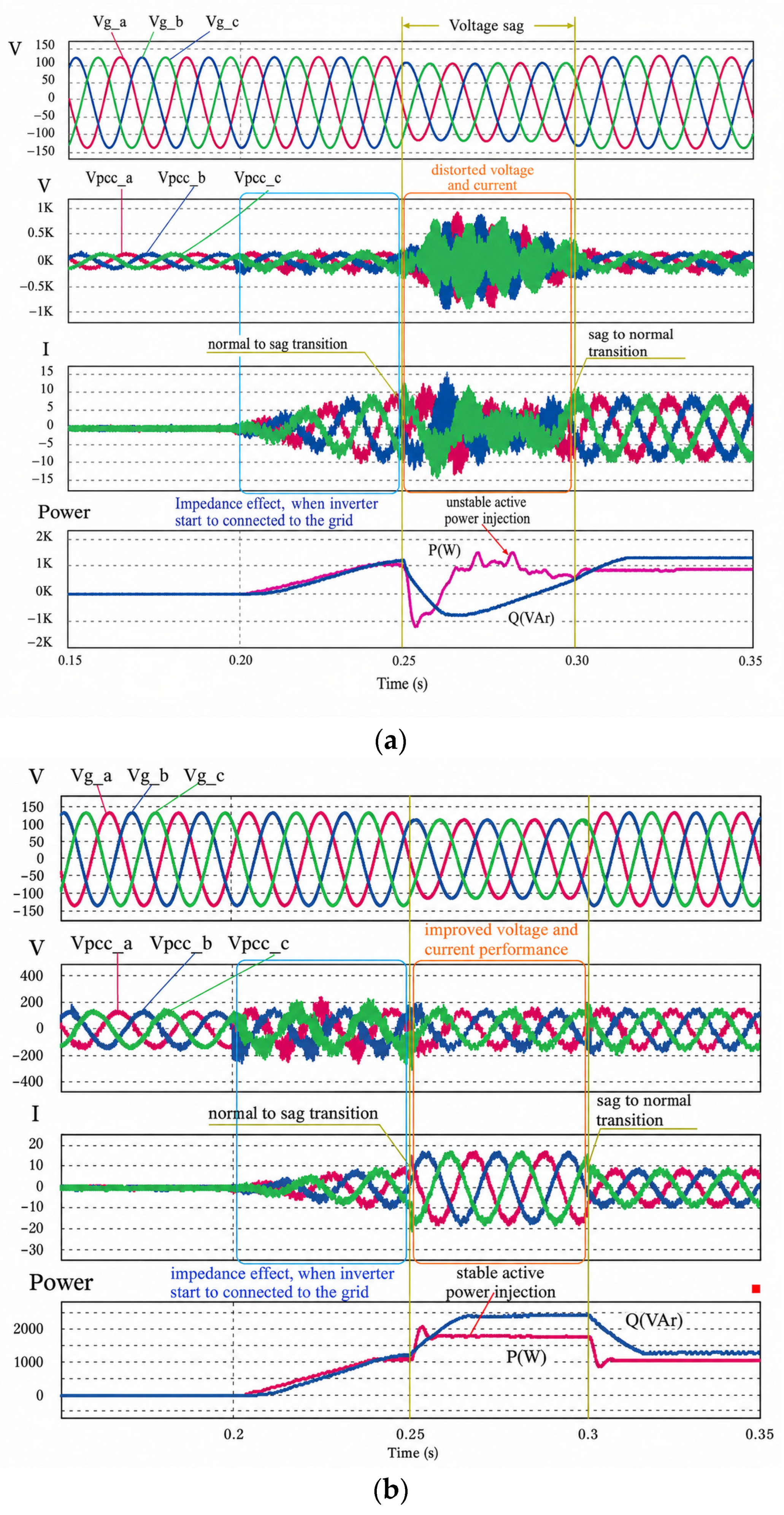
As part of the validation process, both control approaches are tested using an RLC local load comprising a 55 W resistor, a 10 mH inductor, and a 1 nF capacitor. The simulation shown in Figure 9 represents one such case. In this case, the inverter (1) is configured, at first, to be in “Stand Alone” mode to support the local load. and then, at 0.2 s, it is connected to the grid and (2) then experiences sags to the grid for the period of 0.25 s to 0.3 s. The response to the local RLC load and the local feeder impedance causes the inverter current and voltage to be heavily distorted during sags. The conventional droop scheme in Figure 9a offers more distorted current and voltage signals and unstable active power injections. Conversely, the AcDC droop scheme in Figure 9b provides more stable active and reactive power injections and, therefore, offers significant improvements in inverter current and voltage profiles, even under complex load conditions.
Figure 9.
Comparison between schemes to handle voltage sag under RLC load (R = 55 Ω, L = 10 mH, C = 1 nF): (a) conventional droop control; (b) autocorrection droop control.
Table 3 summarizes the results from the resistive load case. It includes the response times of the active and reactive power components, as well as the stability of their responses. In all cases, the proposed AcDC method either improves the voltage restoration times at the PCC and faster power recovery settling times or provides results similar to those of the baseline method. Accompanied by the RLC load results, the results clearly show the benefits of autocorrection droop control. The enhanced capability of the DG unit is demonstrated across all loading conditions and provides a framework for analyzing the LVRT and the different levels of load sagging during the time intervals.
Table 3.
Steady-state response of P and Q for both the conventional and proposed strategies.
3.2. LVRT Performance Under Different Voltage Sag Events
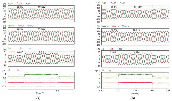
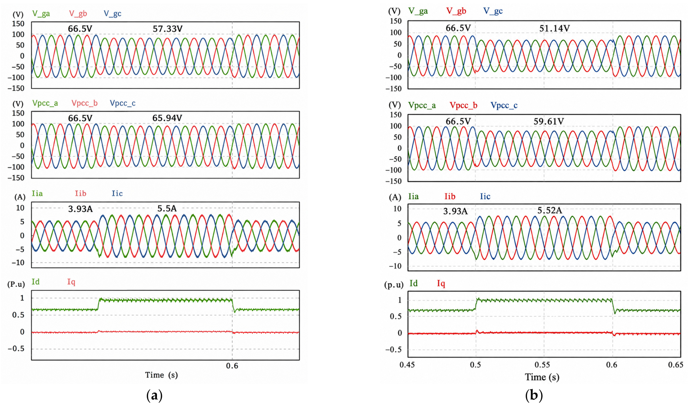
By injecting a combination of active and reactive power (ARP), the autocorrection droop control approach signals voltage recovery to support grid resilience. Reactive power and active power (P and Q, respectively) typically result from a grid fault. The controller’s response is illustrated in the sags shown in Figure 10a,b. During the controller’s injection of grid ARP due to a voltage drop from the reference of 1.0 (66.5 V) to a sag of 0.862 (57.33 V), the PCC voltage increased from 0.992 V to 65.94 V, as the output current increased from 5.5 A to 3.93 A. In contrast, the autocorrection droop control approach improved the PCC voltage to 59.61 V at a sag of 0.769 (51.14 V).
Figure 10.
Simulation result of autocorrection droop control in different sag events: (a) Vg drops to 57.33 V; (b) Vg drops to 51.14 V.
The analysis confirms the existence of a critical operation point for the autocorrection droop control strategy. It was found that full recovery to the normal operating range was only possible for sag depths of about 0.78 p.u. (51.87 V). If the support grid sag is below 0.78 p.u., the controller cannot restore the PCC voltage to its nominal value. This transition point marks the upper limit of the proposed system to provide PCC voltage support and stabilize the grid during severe disturbances.
The ACL-RPC strategy supports the grid by managing the constraints of a current-limited, reactive priority framework. It provides sag-supporting reactive current command during severe voltage sags, it guarantees voltage support via the voltage support logic, and it manages the supporting current to ensure it does not exceed the converter’s constraints.
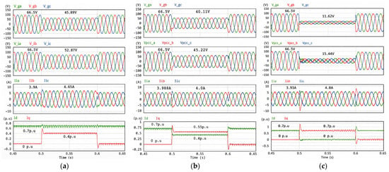
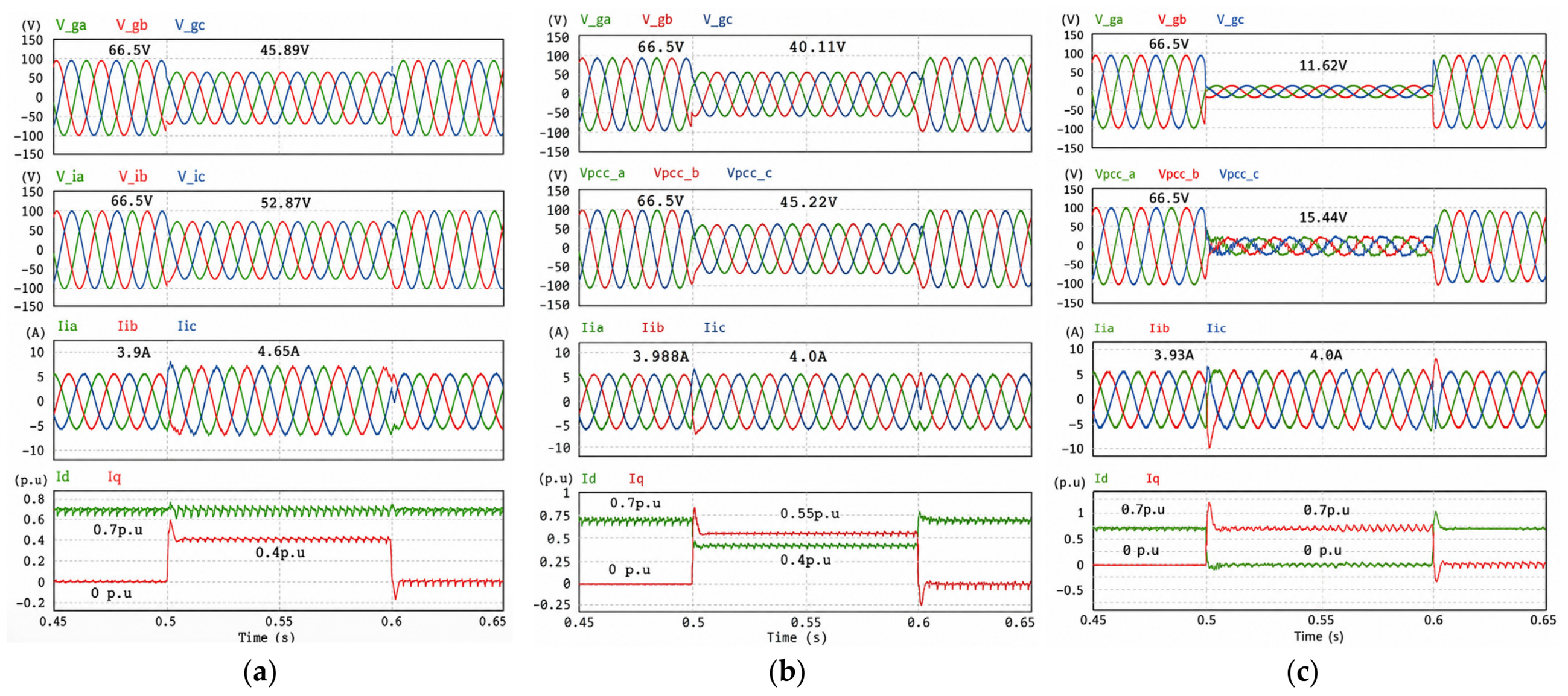
Without the converter’s constraints, DG supports active current by maintaining a reactive load closer to the sags, as seen in Figure 11a. Thus, DG provides support in the sags while maintaining the recovery of the voltage to levels close to about 0.8 p.u. during the low-voltage ride-through time, and manages it by p.u. and p.u.
Figure 11.
Simulation result of ACL-RPC in different voltage sags: (a) ; (b) .; (c) .
When the PCC voltage falls to 0.7 p.u. or less, the controller switches to reactive priority operation. During this low-voltage condition, the controller adds more of the quadrature component () of the current while reducing the direct component () of the current. It is done while the current is within the limit. This behavior is demonstrated in Figure 11b, when the PCC voltage sags to 0.6 p.u. was 0.55 p.u., and was 0.4 p.u., with the result that the DG current was kept at 4.0 A, and improved to about 0.69 p.u. within the prescribed LVRT time. In an ultra-weak grid (Figure 11c), the voltage collapses to around 0.17 p.u., and then ACL-RPC applies the maximum reactive current (0.7 p.u.) and sets the active current to zero. It accomplishes the goal of riding through the fault while maintaining the maximum current, without further stressing the converter beyond its limits. During the fault condition, ACL-RPC enables the controlled operation to switch from the active role at moderate sags to the reactive, restricted current maintaining function while fulfilling the LVRT requirements.
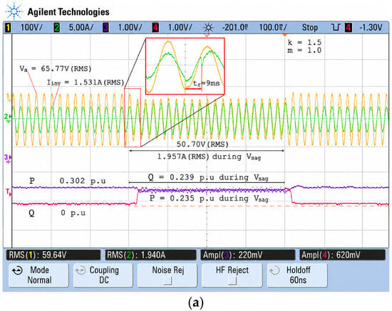
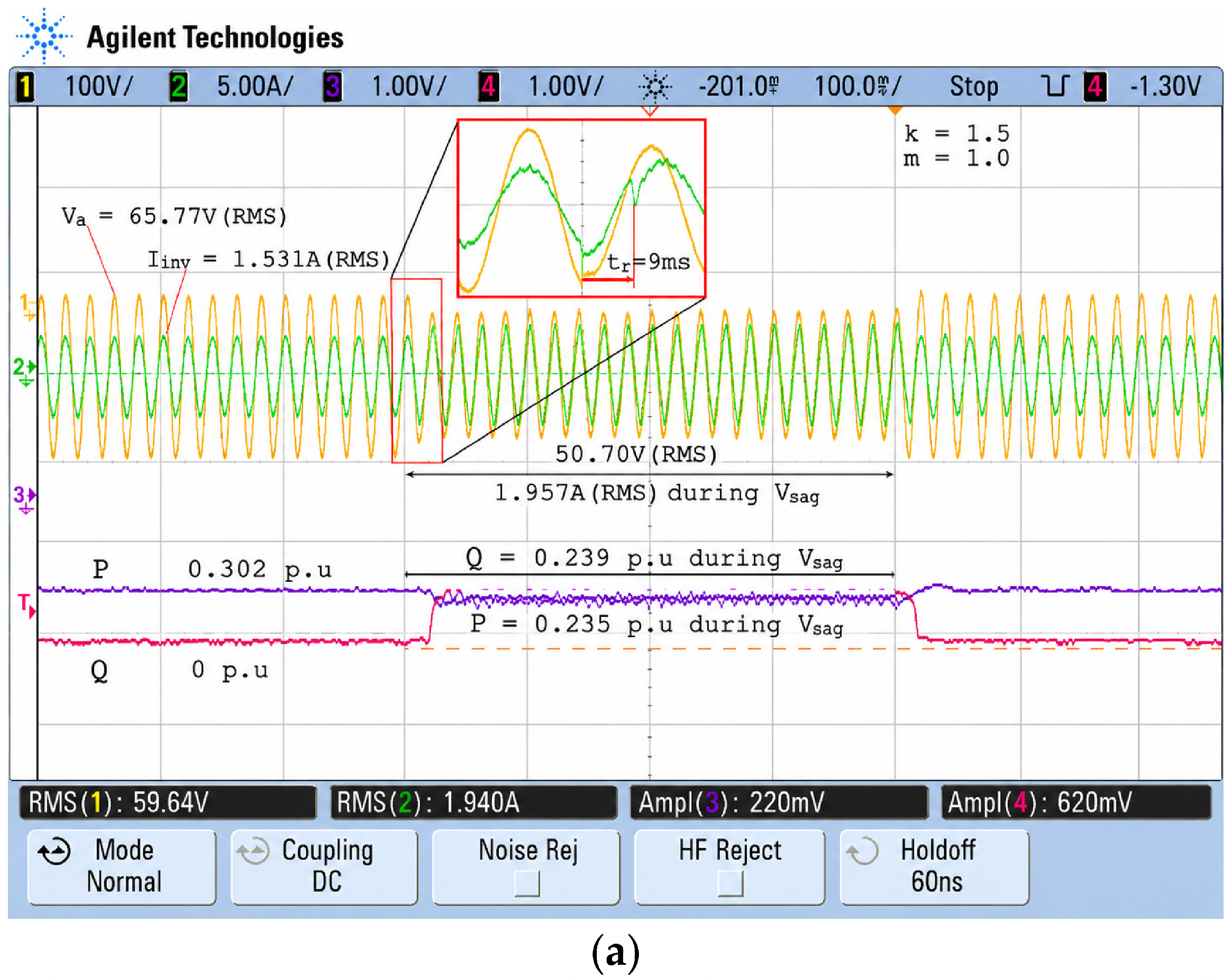
The results in Figure 12 confirm the functionality of the ACL-RPC strategy in supporting the grid during a voltage sag, as evidenced by the controller’s different behaviors. Figure 12a shows the controller’s response to the sag event by adjusting the reactive current reference to support the sagged PCC voltage to 50.70 V (RMS). During the sag event, the inverter output was 1.957 A (RMS), and the system successfully balanced reactive power at the output while remaining active, with P ≈ 0.235 p.u. and Q ≈ 0.239 p.u., to comply with the ride-through requirements.
Figure 12.
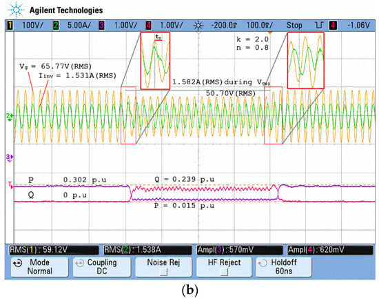
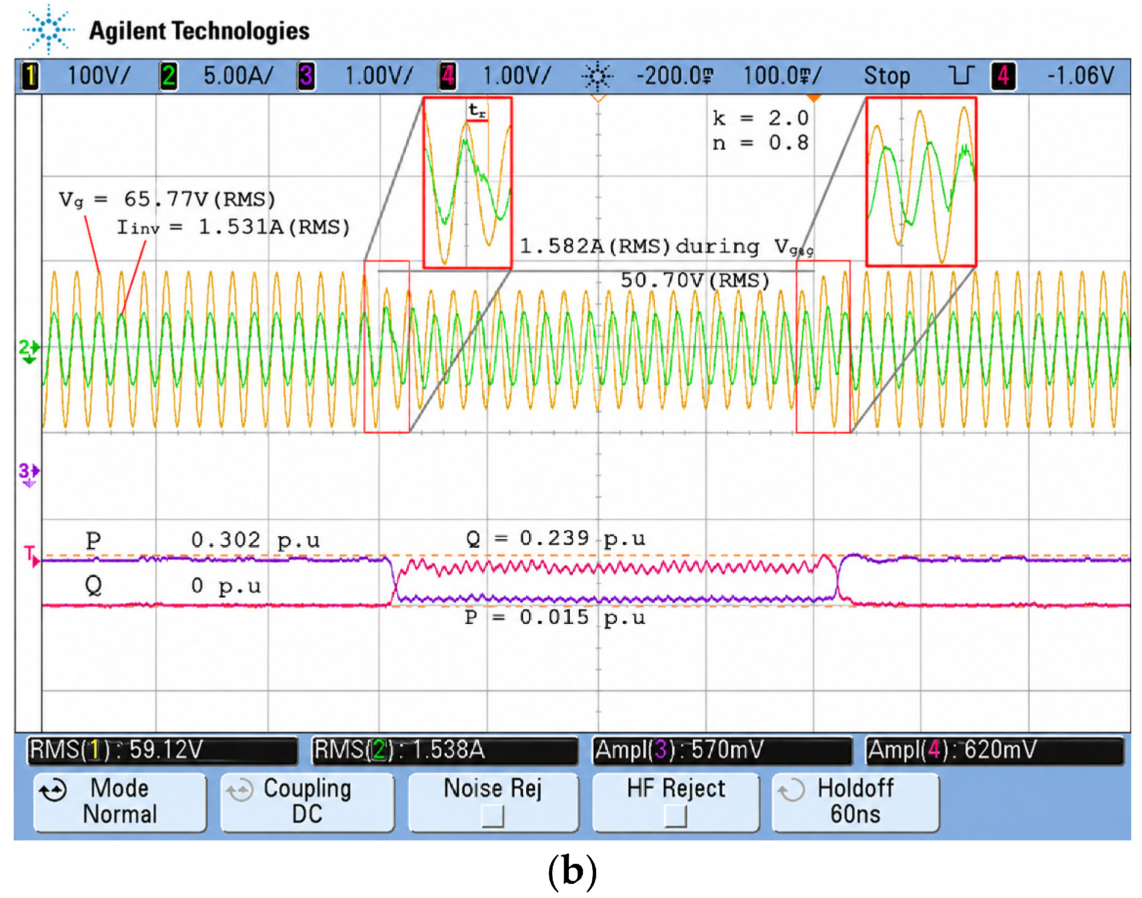
Experimental results in different LVRT strategies: (a) ; (b) .
In Figure 12b, the system was able to perform under the current limit , and the controller shifted active power to reactive power to support the grid under more restrictive conditions. For the case of a voltage sag to 50.70 V (RMS), changing power output was required, whereby ACL-RPC reacted to limit to a quarter of a unit, which was within the protection limit. The experimental results validate that the ACL-RPC architecture provides a continuous, automatic shift to the converter to protect the hardware, meeting predefined LVRT requirements.
4. Discussion
4.1. Transient Response and Voltage Recovery
In this segment, the AcDC and ACL-RPC strategies are reviewed for their transient response and voltage recovery. Specifically, the two strategies are analyzed for their performance during a voltage sag. As shown in Figure 13, both strategies are designed to allow an inverter to recover voltage within control (safe) limits. It can be seen from the figure that the strategies strive to (grid) support under fault conditions as well as provide (grid) support during fault conditions. Regarding the efficiency and reliability of these control strategies, the figure illustrates how they handle grid disturbances.
Figure 13.
Optimized energy delivery strategy during grid voltage sag.
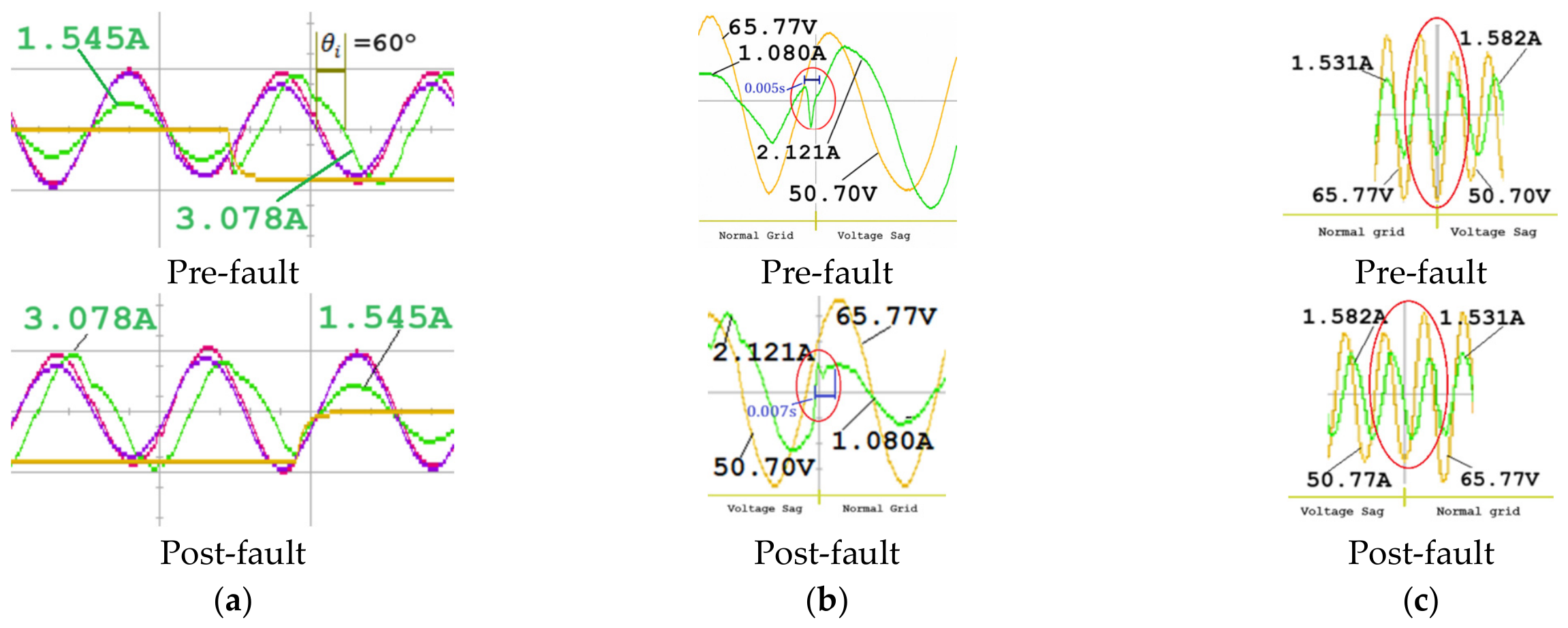
Complementary to grid support strategies, the AcDC methodology is designed to adjust the droop control coefficients as the grid voltage sags. The semantics of the methodology can represent sag control; thus, from the collection of the experimental data, when the grid voltage sags to 0.78 p.u., the inverter sag control can increase the reactive power (current) to 3.078 A, while the recovery of the grid voltage is controlled to be as smooth and steady as possible. The pre-fault conditions collection shows the inverter’s sag control at 1.545 A and is able to control the grid to 65.77 Vic during output sag, while the post-fault conditions collection shows reactive power at 1.545 A. In this sense, this methodology shows that AcDC (i.e., sag control) can restore the system to the pre-fault condition while controlling the overshoot of the grid disturbance and minimizing recovery time to an efficient level.
The transition point observed in the 0.78 p.u. voltage sag should not be considered an inherent limitation of the AcDC control architecture. Instead, the operating boundary is determined by the grid voltage support range of the inverter for the specified system parameters such as the inverter current rating, grid impedance, and droop control coefficients. With the increase in the voltage sag depth, the reactive current demand increases for compensating the voltage deviation, and thus the remaining current margin for restoring the voltage becomes smaller. The ability of the AcDC method to bring the PCC voltage back to the nominal value is limited when the required compensation is close to the converter current limit. Therefore, the 0.78 p.u. transition presented in this work is a parameter-dependent operational boundary of the investigated system and not a universal threshold of the proposed methodology.
An important aspect of the ACL-RPC strategy is the application of both active power limiting and current limiting to protect against overcurrent conditions that may occur during voltage sag events. The implementation of the ACL-RPC strategy showed that, at a grid voltage sag of 0.77 p.u., the inverter current was limited to 2.121 A to support the voltage during that loss. By controlling active power levels and reducing current levels as the grid voltage sagged, the inverter was able to operate within threshold limits and support grid voltage recovery. Despite the limitations of the ACL-RPC strategy, the current levels were able to support grid voltage recovery by preventing the inverter from exceeding the threshold. After the voltage sag, the system quickly and smoothly returned to the pre-sag condition, with the PCC and inverter current returning to nominal. It further shows the effectiveness and efficiency of the ACL-RPC strategy.
Although the experiments were conducted under balanced three-phase voltage sag conditions, prioritizing reactive current injection may still create a temporary imbalance between the DC-side input power and the AC-side active power delivered by the inverter. When ACL-RPC reduces the active current component to maintain the total converter current within its prescribed limit, excess DC-side energy may accumulate in the DC link capacitor and increase the DC link voltage. The proposed controller includes a supervisory DC link power curtailment mechanism, as illustrated in Figure 4, to reduce the source power reference when the DC link voltage exceeds its reference value. However, the DC link voltage waveform was not recorded as a reported performance variable in the present tests. Therefore, the results confirm AC-side current limit compliance and PCC voltage support performance but do not independently establish the DC link overvoltage margin or validate the effectiveness of the DC-side protection mechanism. This represents a limitation of the present study and should be investigated through direct DC link voltage measurements in future work.
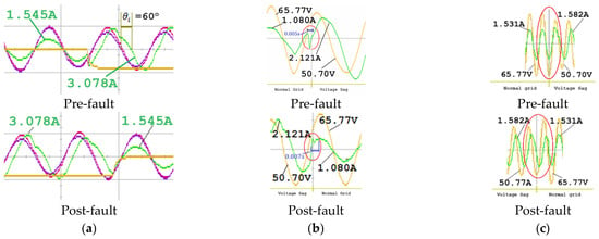
Additionally, Figure 14 depicts the transient response to a 0.77 p.u. sag. In the autocorrection droop mode (Figure 14a), the inverter current advances with an approximate 60° phase shift, ranging from 1.545 A to 3.078 A, suggesting that the inverter provides the PCC with additional reactive power. After the fault is cleared, the PCC voltage does not overshoot appreciably as the inverter current returns to the pre-fault 1.545 A value, indicating a critically damped response. In the sag response mode that is focused on the the current again shows a phase shift; however, an inverter voltage drop from 65.77 V to 50.70 V, paired with the PCC voltage drop, occurs, resulting in a 2.121 A response that stabilizes the PCC voltage and completes the transition to a new steady state in half a cycle (Figure 14b).
Figure 14.
Grid fault transient response during a voltage sag event: (a) autocorrection droop control; (b) ; (c) .
The impact of the current limiting action is captured in Figure 14c. Current thus minimally increased from 1.531 A to 1.582 A. It ensures voltage recovery while avoiding overcurrent damage. The converter supports recovery from a sustained fault within its limit. Among the sag levels considered, ACL-RPC performance indicators (minimum PCC voltage, settling time, and current overshoot) consistently improve fault recovery, current stretching, and post-fault recovery. The placement of ACL-RPC along the LVRT control curve, due to its sag control capability, supports effective LVRT compliance during grid voltage sags. To provide an overall summary of the investigated operating conditions, Table 4 consolidates the main simulation and experimental results of the proposed AcDC–ACL-RPC framework. The table highlights the applied voltage sag levels, corresponding control strategies, main control responses, and observed LVRT performance outcomes.
Table 4.
Summary of simulation and experimental validation results.
Although the proposed AcDC-ACL-RPC system indicates stable operation through simulation and experimental validation, no formal analytical stability proof was produced in this study. The stability analysis is conducted based on the transient performance indices, e.g., the PCC voltage recovery, current limit compliance, and post-fault reaction for the tested operating conditions. Future studies will include a thorough stability analysis by adopting Lyapunov-based methodologies, impedance-based analysis, or passivity theory to get theoretical stability margins under various grid circumstances and parameter uncertainties.
Finally, the AcDC control integrated with the ACL-RPC control shows a high level of performance in edge case management for voltage sags, grid safety, and inverter control persistence in fault conditions. In-depth analysis of the fault control features of the proposed control strategies shows positive shift and recovery responses for grid-integrated distribution generation systems. The testing scenarios highlighted the importance of sag and fault control in reactive power offer, active power control, and current management for safe grid-integrated operation, in line with industry control and performance regulations.
4.2. Comparative Analysis with Existing Methods
This section examines the proposed AcDC-ACL-RPC strategy to see how effective it is at limiting inverter current while stabilizing power support during low-voltage ride-through LVRT operation. The results are analyzed against current limiting strategies that are currently leading edge in technology as cited in [26,27,28,29]. These include reference-based current shaping, magnitude saturation control, dual-sequence regulation, and two-stage limiting approaches.
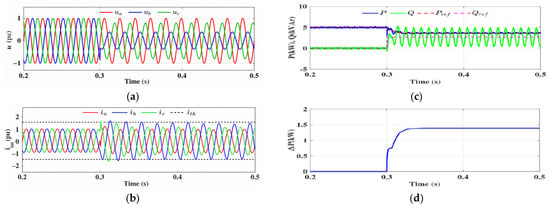
Reference [26] describes LVRT current limiting that involves reducing active power injection while the inverter current is still within limit, enabling the support of reactive power for active voltage regulation. As can be seen in Figure 15, the fault period results in a rapid curtailment of active power, resulting in a sharp decrease in active power in a very short time, while reactive power is retained to support recovery of grid voltage. While this method does avoid overcurrent and offers LVRT compliance, the effect of the method is an abrupt reduction in active power and current waveform distortion in the case of unbalanced fault conditions. Additionally, the active current limiting method is implemented once the current is within limit; hence, the method is ineffective at suppressing transient inrush currents during fault conditions.
Figure 15.
Current limiter strategy under unbalanced severe fault, by [26]: (a) grid voltages; (b) injected currents; (c) injected active and reactive powers; (d) desired change in active power.
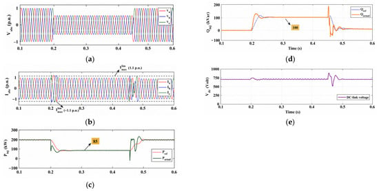
Reference [27] addresses LVRT current limiting by altering the d–q current references with a saturation constraint to keep inverter current at the allowable limit (1.1 p.u.). As seen in Figure 16, during balanced voltage sags, the inverter’s rising current is limited after the fact by reference scaling. Reactive current is injected to assist in the recovery of the PCC voltage, while current control causes the active power to drop and level off at about 85 kW. While the approach limits overcurrent and maintains LVRT, it causes sudden drops in active power and changes in reactive power during the fault. The reference saturation method causes an indirect current limiting effect and may impede the approach’s ability for smooth current redistribution and optimum dynamic response during fast voltage perturbations.
Figure 16.
LVRT performance under balanced fault condition, by [27]: (a) three-phase PCC voltages experiencing a 45% voltage reduction; (b) injected PCC currents constrained within the allowable current limit of 1.1 p.u.; (c) active power regulation with braking chopper activation during the voltage sag; (d) reactive power support response complying with IEEE 1547 voltage support requirements; and (e) DC-link voltage regulation under voltage sag operation.
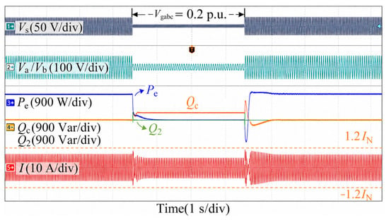
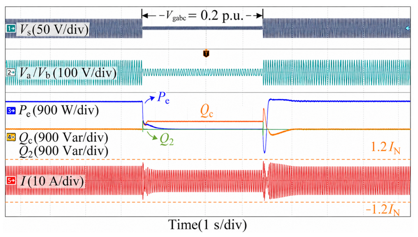
Reference [28] applies LVRT current limiting with a dual-sequence current control method. Here, inverter current is broken down to positive and negative sequence components to manage grid disturbances during symmetrical faults. In the example shown in Figure 17, the grid voltage decreases to roughly 0.2 p.u., and the inverter current increases, but it is constrained to a limit of about 1.2 p.u. during the fault. The controller chooses to inject reactive power in support of the recovery of grid voltage and, in doing so, decreases the active power output to keep the current within the limit. Unfortunately, the overshoot and oscillation of transient current, in both active and reactive power, during the fault show a delay in response and a lack of full optimization of the coordination between the power components, while the current limiting action is also not immediate. This shows that the LVRT conditions result in a lack of effective transient response and power redistribution.
Figure 17.
Current limiting under symmetrical voltage sag, by [28].
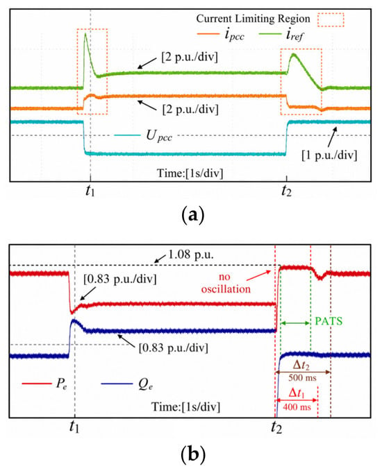
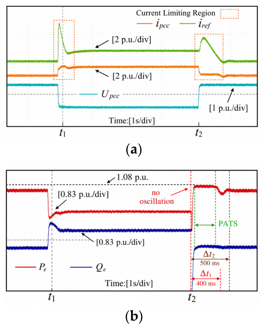
Reference [29] proposes a two-stage current limiting (TSCL) strategy for grid-forming VSG systems during LVRT when different current limits are utilized during fault and post-fault stages. As seen in Figure 18, if a critical case of voltage sag occurs (down to 0.4 p.u.), inverter current is constrained, and a strict limit is employed to ensure safe operation. Instead, grid support of voltage and current transfer constraints is provided by the increase in reactive power and the decrease in active power, respectively. After the fault is cleared, the current limit is set to the value of Ilim2 = 1.08 p.u. for the purpose of the positive enhancement of the quick recovery and the resynchronization of the system. The TSCL method reduces the post-fault oscillation and improves the system recovery and synchronization stability. However, the method indicates that the limiting of the current is done in discrete steps, which provides limited flexibility to the various fault levels. In addition, a transient state of current increase is observed before the complete limitation of the current is reached, and the allocation of current between the active and reactive components is not optimized.
Figure 18.
Two-stage current limiting, by [29]: (a) current-limiting action during fault occurrence at t1 and fault clearance at t2; (b) active and reactive power responses, showing limited active-power overshoot to 1.08 p.u.
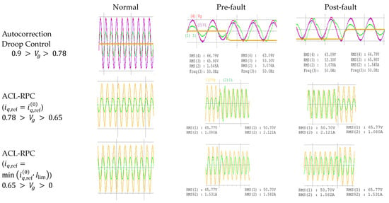
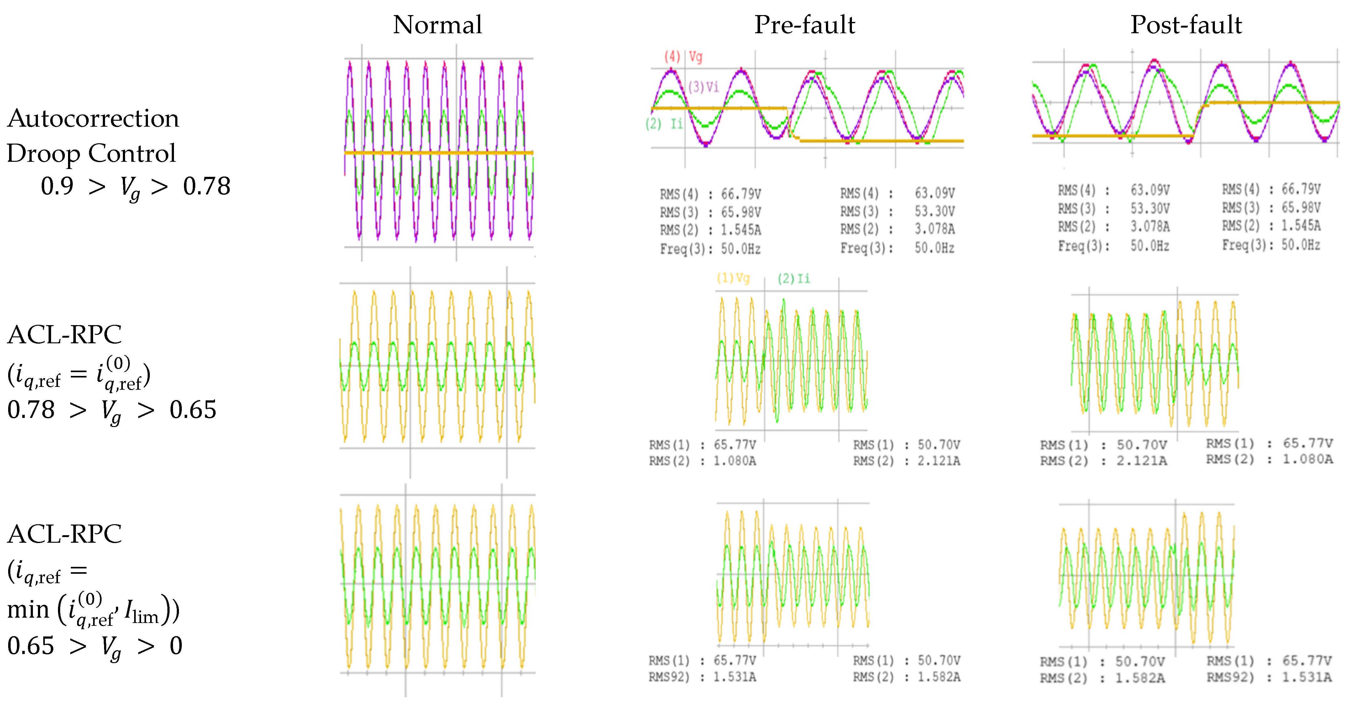
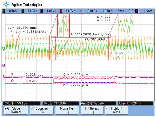
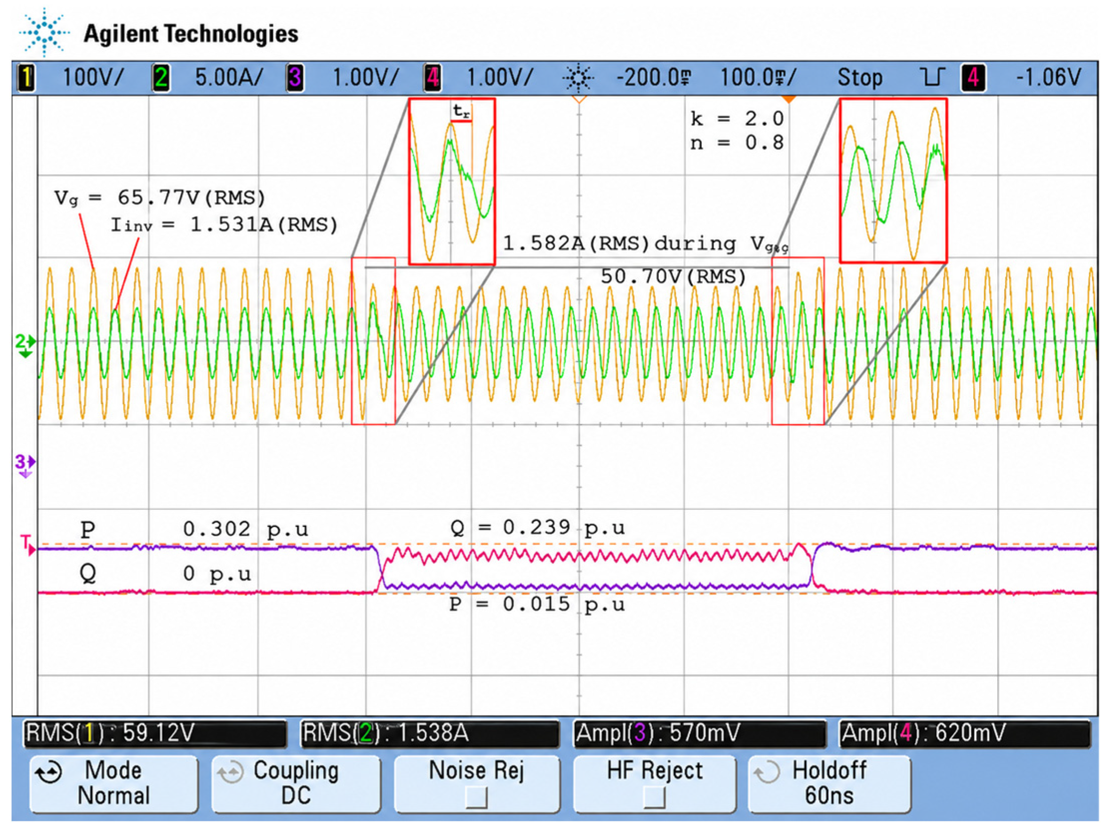
The experimental results demonstrate the proposed AcDC and ACL-RPC strategies in LVRT scenarios successfully, as illustrated in Figure 19. In the waveform, during the voltage sag, the PCC voltage drops to about 50.7 V Rms, while the inverter current is limited to the rated value of 1.53–1.58 A Rms, showing good current limit without overshoot. Unlike traditional methods that use post-saturation clipping or discrete limit stages, the proposed controller provides continuous regulation of the current by dynamically reallocating the active and reactive values. During the fault, the active power is reduced from 0.302 p.u. to 0.239 p.u. with minimal changes to the reactive power, showing proper LVRT power balancing. The control strategy also optimizes the LVRT control problem, as the dynamic process is free from steps or oscillations.
Figure 19.
Proposed AcDC and ACL-RPC.
The AcDC and ACL-RPC method achieves continuous and explicit current regulation via real-time active/reactive current redistribution, which operates under active current limits, as well as the ability to change voltage references via the AcDC loop. This integrated structure provides smooth active power derating, stable reactive power support, and efficient transient inrush current suppression at the time of fault occurrence. In addition, and contrary to [26,27,28,29], the proposed method offers a fully integrated LVRT control framework that does not depend on post-saturation correction, discrete mode switching, or sequence domain coupling. It provides a fully integrated LVRT control framework that guarantees both transient behavior and post-fault recovery stability. As a result, the current smoothness, overshoot, and dynamic stability improve during critical voltage sags.
5. Conclusions
This paper proposed a coordinated LVRT control method for three-phase converter-interfaced distributed generation systems that utilizes autocorrection droop control (AcDC) and ACL-RPC. The proposed method mitigates drawbacks of conventional LVRT methods that utilize post-saturation current limiting, indirect reference adjustment, or discrete switching. These conventional methods suffer from inadequate transient suppression and low adaptability for severe voltage sags. The AcDC mechanism offers flexible adjustment of voltage references and severity, and the ACL-RPC mechanism provides stringent current control of the converter through the time-based adjustment of active and reactive currents. This combination provides continuous control of current, active power reduction, prioritized reactive power control, and adequate voltage assistance. This can be performed without estimation of grid impedance or fault categorization. Conventional methods utilize abrupt switching of the control modes to regulate power, which the proposed method avoids to gain better performance during transient recovery. A notable aspect of this work is the observation of a practical operating limit of approximately 0.78 p.u. that offers guidance for the LVRT control of inverter-interfaced distributed generation systems and defines the boundary between voltage restoration-dominant operation and current-limited reactive priority operation. The simulation and experimental results demonstrated improved AC-side LVRT performance, PCC voltage support, active/reactive current redistribution, and compliance with the prescribed converter current limit under the investigated balanced three-phase voltage sag conditions. Although the controller incorporates a DC link supervisory power curtailment mechanism, the DC link voltage response was not separately validated in the present study. Consequently, further experimental assessment is required to confirm the DC-side overvoltage margin and protection performance during sustained active power curtailment.
Author Contributions
Conceptualization, F.I. and L.J.A.; Methodology, F.I.; Software, F.I.; Validation, S.M.M.M., M.K.R. and Z.H.; Formal analysis, F.I., S.M.M.M. and M.K.R.; Investigation, F.I. and Z.H.; Writing—original draft, F.I.; Writing—review & editing, F.I. and L.J.A.; Supervision, L.J.A.; Funding acquisition, L.J.A. All authors have read and agreed to the published version of the manuscript.
Funding
This research was funded by [Airlangga University] grant number [150/B/DST/UN3.AGE/HK.07.01/2026].
Data Availability Statement
The original contributions presented in this study are included in the article. Further inquiries can be directed to the corresponding author.
Acknowledgments
The authors would like to thank Universitas Airlangga for supporting this research through The Airlangga Post-Doctoral Fellowship Program (Ref. No. 150/B/DST/UN3.AGE/HK.07.01/2026). Their support made this study possible.
Conflicts of Interest
The authors declare no conflict of interest.
References
- de Almeida, L.R.; da Costa Lima, R.N.; Junior, J.R.M. Analysis of fault current contributions from small-scale single-phase photovoltaic inverters and their impacts on the protection of electric power distribution systems. IET Gener. Transm. Distrib. 2024, 18, 13431359. [Google Scholar] [CrossRef] [Scilit]
- Li, G.; Zhao, R.; Zhang, Z.; Xue, Y. Equivalent method of grid-connected photovoltaic sources for medium-voltage distribution networks fault analysis. Electr. Power Syst. Res. 2025, 238, 111179. [Google Scholar] [CrossRef] [Scilit]
- Etanya, T.F.; Tsafack, P.; Ngwashi, D.K. Grid-connected distributed renewable energy generation systems: Power quality issues, and mitigation techniques—A review. Energy Rep. 2025, 13, 3181–3203. [Google Scholar] [CrossRef] [Scilit]
- Benyamina, F.; Ahmed, H.; Benrabah, A.; Khoucha, F.; Achour, Y. Sequence extraction-based low voltage ride-through control of grid-connected renewable energy systems. Renew. Sustain. Energy Rev. 2023, 183, 113508. [Google Scholar] [CrossRef] [Scilit]
- Selim, F.; Aly, M.; Megahed, T.F.; Abdelkader, S.M. Low voltage ride through enhancement techniques on photovoltaic systems: A comprehensive review. Appl. Energy 2026, 402, 126955. [Google Scholar] [CrossRef] [Scilit]
- Singh, A.K.; Choudhury, N.B.D.; Singh, J.; Tiwari, D.K. Multi-functional low voltage ride-through control strategies for grid-interfaced solar power plants: A comprehensive review. Appl. Energy 2026, 415, 127885. [Google Scholar] [CrossRef] [Scilit]
- Ordono, A.; Sanchez-Ruiz, A.; Zubiaga, M.; Asensio, F.J.; Cortajarena, J.A. Current limiting strategies for grid forming inverters under low voltage ride through. Renew. Sustain. Energy Rev. 2024, 202, 114657. [Google Scholar] [CrossRef] [Scilit]
- Rai, R.; Singh, B. Converter Control During Low Voltage Ride Through Operation for Grid-Interfaced Solar PV Battery Assisted System. IEEE Trans. Ind. Electron. 2023, 70, 9181–9191. [Google Scholar] [CrossRef] [Scilit]
- Fan, B.; Wang, X. Fault Recovery Analysis of Grid-Forming Inverters With Priority-Based Current Limiters. IEEE Trans. Power Syst. 2023, 38, 5102–5112. [Google Scholar] [CrossRef] [Scilit]
- Khayat, Y.; Chen, P.; Bongiorno, M.; Johansson, B.; Majumder, R. FRT Capability of Grid-Forming Power Converters: An Antiwindup Scheme. IEEE Trans. Power Electron. 2024, 39, 12842–12855. [Google Scholar] [CrossRef] [Scilit]
- Wang, H.; Geng, J.; Feng, B.; Xie, D.; Zhang, P.; Wang, L.; Yao, J. Application and impact of multi-power quality objective optimization control in low-voltage ride-through for grid-connected inverters. Int. J. Electr. Power Energy Syst. 2025, 170, 110890. [Google Scholar] [CrossRef] [Scilit]
- Maganti, S.; Padhy, N.P. An Advanced Control Strategy for a Weak Grid-Connected DG for Enhancing Voltage Support During Co-occurrence of Sag and Swell. IEEE Trans. Power Electron. 2024, 39, 1644–1655. [Google Scholar] [CrossRef] [Scilit]
- Wen, F.; Acuna, P.; Yuan, Z.; Cui, C.; Aguilera, R.P.; Ghias, A.M.Y.M. Many-Objective Optimized Current Reference Generation Strategy for Inverter-Based Distributed Generators During Unbalanced Voltage Sags. IEEE Trans. Power Electron. 2025, 41, 7926–7942. [Google Scholar] [CrossRef] [Scilit]
- Desai, M.A.; He, X.; Huang, L.; Dörfler, F. Saturation-informed current-limiting control for grid-forming converters. Electr. Power Syst. Res. 2024, 234, 110746. [Google Scholar] [CrossRef] [Scilit]
- Baeckeland, N.; Chatterjee, D.; Lu, M.; Johnson, B.; Seo, G.-S. Overcurrent Limiting in Grid-Forming Inverters: A Comprehensive Review and Discussion. IEEE Trans. Power Electron. 2024, 39, 14493–14517. [Google Scholar] [CrossRef] [Scilit]
- Wang, J.; Zhang, X. Active Power and Voltage Cooperative Control for Improving Fault Ride-Through Capability of Grid-Forming Converters. IEEE Trans. Ind. Electron. 2024, 71, 12301–12311. [Google Scholar] [CrossRef] [Scilit]
- Arjomandi-Nezhad, A.; Guo, Y.; Pal, B.C.; Yang, G. Modeling Fault Recovery and Transient Stability of Grid-Forming Converters Equipped With Current Reference Limitation. IEEE Trans. Energy Convers. 2025, 40, 1140–1152. [Google Scholar] [CrossRef] [Scilit]
- Deng, H.; Qi, Y.; Fang, J.; Tang, Y.; Debusschere, V. A Robust Low-Voltage-Ride-Through Strategy for Grid-Forming Converters Based on Reactive Power Synchronization. IEEE Trans. Power Electron. 2023, 38, 346–357. [Google Scholar] [CrossRef] [Scilit]
- Fernández, J.D.; Eloy-García, J.; Navarro, E.R.; Gómez, S.A.; Amenedo, J.L.R. Low-Voltage Ride-Through Algorithm for Grid-Forming Converters. IEEE Trans. Power Electron. 2025, 40, 303–315. [Google Scholar] [CrossRef] [Scilit]
- Sun, H.; Lin, X.; Wei, J. Transient Synchronization Stability and Enhanced-LVRT Scheme for Grid-Forming Converters Considering Current Limitation and Nonlinear Damping Simultaneously. IEEE Trans. Energy Convers. 2025, 40, 2466–2484. [Google Scholar] [CrossRef] [Scilit]
- Correia, A.F.M.; Cavaleiro, M.; Neves, M.; Coimbra, A.P.; Almeida, T.R.O.; Moura, P.; de Almeida, A.T. Architecture and Operational Control for Resilient Microgrids. In Proceedings of the 2024 IEEE/IAS 60th Industrial and Commercial Power Systems Technical Conference (I&CPS); IEEE: New York, NY, USA, 2024; Volume 2020, pp. 51373–51387. [Google Scholar] [CrossRef] [Scilit]
- Ismail, F.; Jamaludin, J.; Rahim, N. Improved active and reactive power sharing on distributed generator using auto-correction droop control. Electr. Power Syst. Res. 2023, 220, 109358. [Google Scholar] [CrossRef] [Scilit]
- Wang, J.; Liu, Z.; Feng, K.; Liu, J. An Adaptive Droop and Feedforward Control Based Transient Power Sharing and Decoupling Method for Grid-Forming Inverters in Islanded Microgrids. IEEE Trans. Ind. Electron. 2025, 72, 4800–4810. [Google Scholar] [CrossRef] [Scilit]
- Si, W.; Li, W.; Tashakor, N.; Fang, J. Joint Transient Angle and Voltage Stability Analysis and Enhancement of Grid-Forming Converters. IEEE Trans. Ind. Electron. 2025, 72, 3872–3883. [Google Scholar] [CrossRef] [Scilit]
- Pal, A.; Achlerkar, P.D.; Panigrahi, B.K. Fault-induced current limitation control for grid-forming inverters: A framework for rapid grid code compliance. Electr. Power Syst. Res. 2025, 242, 111471. [Google Scholar] [CrossRef] [Scilit]
- Benyamina, F.; Benrabah, A.; Khoucha, F.; Zia, M.F.; Achour, Y.; Benbouzid, M. Online current limiting-based control to improve fault ride-through capability of grid-feeding inverters. Electr. Power Syst. Res. 2021, 201, 107524. [Google Scholar] [CrossRef] [Scilit]
- Singh, A.K.; Tiwari, D.K.; Choudhury, N.B.D.; Singh, J. A grid-compliant control approach for current reference generation strategy to improve Low-Voltage Ride-Through (LVRT) performance and power management in grid-tied PV system. Comput. Electr. Eng. 2025, 128, 110638. [Google Scholar] [CrossRef] [Scilit]
- Liu, C.; Shen, Y.; Chen, A.; Chi, S.; Liu, T. Transient Current Limiting Method of CHB-Based GFM Converters With Dual-Sequence Dynamic Reactive Power Support Under Voltage Sags. IEEE Trans. Ind. Electron. 2026, 1–13. [Google Scholar] [CrossRef] [Scilit]
- Tian, W.; Zhang, L.; Dai, D.; Zhang, J.; Zhang, Y.; Li, B.; Yang, W.; Lan, F.; Li, J. Two-Stage Current Limiting Method for Fault Ride-Through Enhancement of Virtual Synchronous Generator. IEEE Trans. Ind. Electron. 2026, 1–14. [Google Scholar] [CrossRef] [Scilit]

Disclaimer/Publisher’s Note: The statements, opinions and data contained in all publications are solely those of the individual author(s) and contributor(s) and not of MDPI and/or the editor(s). MDPI and/or the editor(s) disclaim responsibility for any injury to people or property resulting from any ideas, methods, instructions or products referred to in the content. |
© 2026 by the authors. Licensee MDPI, Basel, Switzerland. This article is an open access article distributed under the terms and conditions of the Creative Commons Attribution (CC BY) license.