


Abstract
This article investigates the thermal performance of a conventional W-70 large-panel building system and a modern prefabricated wall system incorporating recycled expanded polystyrene (EPS) regranulate. The study aims to compare the thermal performance of two prefabricated wall systems representing different construction technologies and to evaluate the combined influence of their structural and material solutions on heat losses and thermal bridging. Numerical simulations were performed using THERM 7.6 based on the finite element method (FEM). Three representative structural junctions were analysed: the external corner, the external wall-to-internal wall junction, and the floor slab-to-external wall junction. The evaluation included thermal transmittance (U-value), heat flow rate, thermal coupling coefficient, linear thermal transmittance (Ψ), minimum internal surface temperature, and the internal surface temperature factor (fRsi). The results demonstrated that the analysed prefabricated wall system exhibited lower heat losses and improved thermal performance than the conventional W-70 large-panel system. The observed differences reflect the combined effect of the wall build-up, material properties, insulation thickness, and structural junction geometry. The incorporation of recycled EPS regranulate constitutes one of the design features of the analysed wall system and may contribute to more sustainable use of construction materials through the utilisation of recycled polymer waste.
1. Introduction
Prefabrication has for many years been one of the most important directions in the development of industrialized construction. Modern prefabrication systems differ significantly from the large-panel technologies used in the second half of the twentieth century [1,2]. Thanks to advances in modern materials, production automation, and digital design methods, prefabrication has become a process that encompasses almost the entire construction project, from design and manufacturing of components to their transportation and installation on the construction site. This ensures high construction quality, shorter project delivery times, and a reduction in construction waste [3,4,5,6].
In recent years, modular construction has been developing particularly rapidly. An increasing degree of prefabrication means that a significant proportion of construction work is carried out under factory conditions, while activities on the construction site are mainly limited to the assembly of finished elements or modules. Depending on the level of prefabrication, panelized (2D) systems, volumetric modular (3D) systems, and hybrid solutions are used. According to Kim [6] and Zohourian et al. [5] modular prefabrication is currently one of the fastest-growing sectors of the construction industry. In the most advanced systems, as much as 70–95% of the work can be completed off-site, resulting in greater consistency of quality and shorter project delivery times.
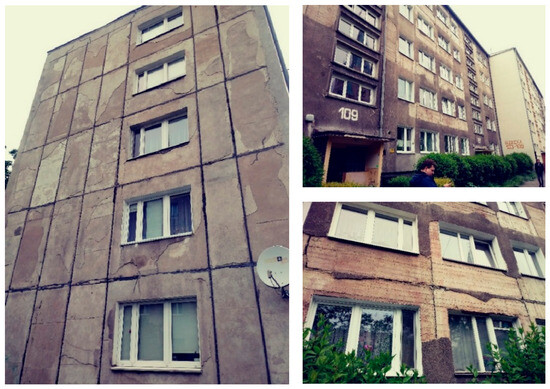
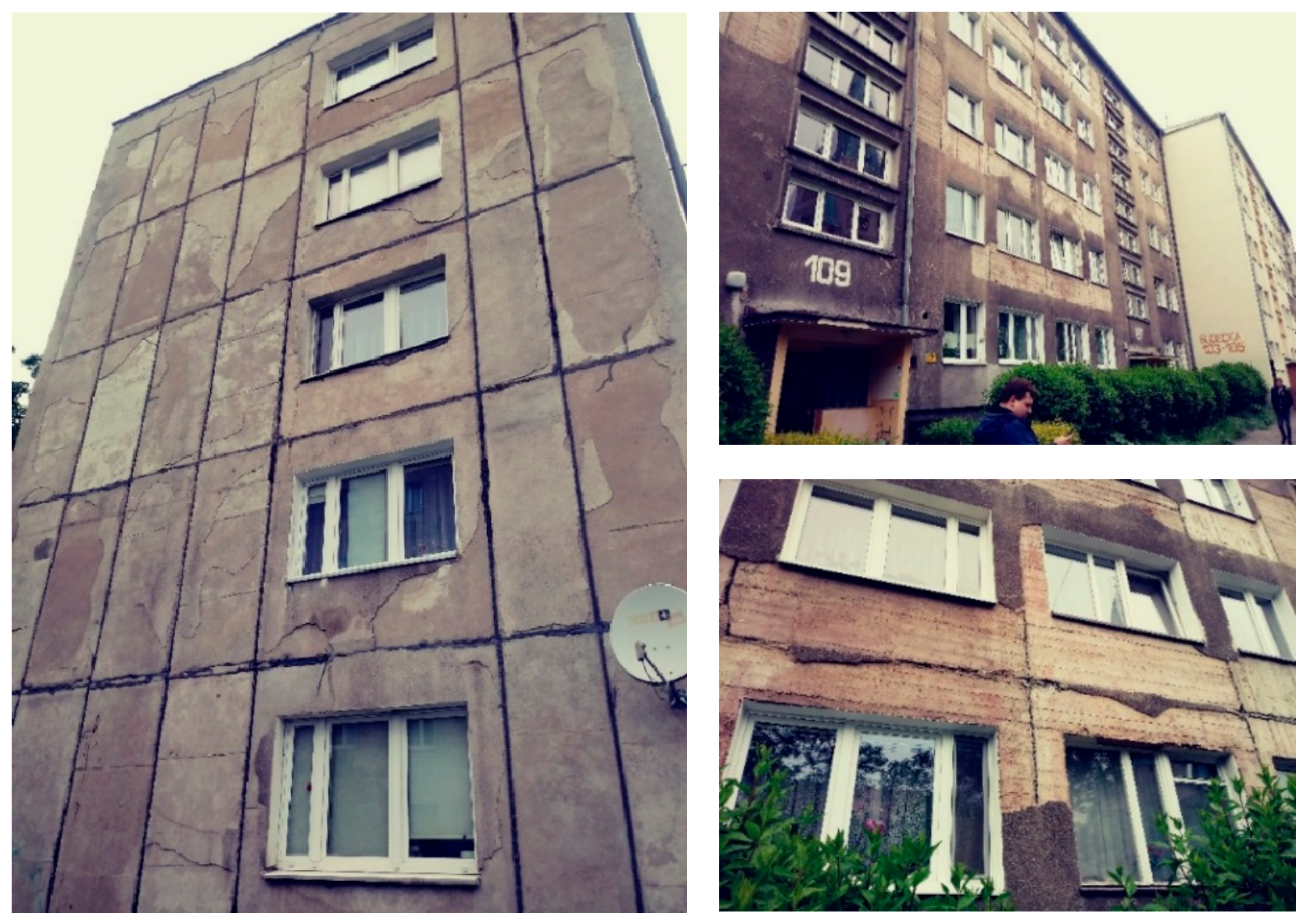
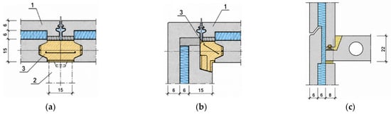
Concrete prefabrication remains an important area of research, as it has been the primary technology used in residential, industrial, and infrastructure construction for several decades. In Poland, Starosolski [7] and others, e.g., Koncz [8,9], made a significant contribution to the development of design principles for precast reinforced concrete structures and their connections, highlighting the key role of joints in ensuring the load-bearing capacity, stiffness, and durability of the structure, as shown in Figure 1. However, experience gained from the long-term operation of large-panel buildings has shown that the connections between prefabricated elements are also among the most vulnerable parts of the building envelope in terms of service performance, including the occurrence of thermal bridges and the associated heat losses.
Figure 1.
Example of a residential building constructed using large-panel technology, showing the joints (connections) between prefabricated façade elements (fot. Author).
As highlighted in recent review studies, despite the discontinuation of new large-panel residential construction, these buildings still constitute a significant proportion of the housing stock in many European countries. Consequently, issues related to the assessment of their technical condition, modernization, and improvement of energy performance remain an important area of research [1,5].
Contemporary prefabrication solutions are primarily focused on improving connection details and reducing thermal bridging through the use of advanced materials, integrated thermal insulation layers, and technologies that enhance the airtightness and durability of joints.
At the same time, the development of prefabrication is closely linked to the ongoing digitalization of the construction process and the implementation of Building Information Modeling (BIM). These technologies improve the coordination of design, manufacturing, and assembly of prefabricated elements. Solutions based on artificial intelligence, robotics, and digital twins further increase production efficiency, enhance quality control, and support logistics management [5,10,11]. Numerous studies have also demonstrated that prefabrication can reduce material consumption, construction waste, and greenhouse gas emissions, thereby supporting the principles of sustainable development [4,6,12].
The research trends presented in the literature indicate that modern prefabrication encompasses a wide range of material and structural solutions, differing in the degree of prefabrication, assembly methods, and fields of application. A summary of the main prefabrication technologies, together with examples of their manufacturers, is presented in Table 1.
Table 1.
Overview of Contemporary Prefabrication Technologies.
Recent studies have shown that the development of prefabricated building envelopes increasingly focuses on combining structural performance, thermal efficiency, durability and sustainability. Sah et al. [30] reviewed contemporary prefabricated wall systems, highlighting the importance of simultaneously considering their structural, thermal and environmental performance. Furthermore, Ibrahim et al. [31] demonstrated that the evaluation of modern building envelope solutions should increasingly incorporate not only energy performance but also environmental and economic criteria. Although the present study focuses exclusively on the thermal performance of prefabricated wall systems and their representative structural junctions, these studies illustrate the broader context of sustainable building envelope development.
The conducted review indicates that contemporary prefabrication is moving towards increasing the level of factory completion of building components, reducing construction time, and improving the energy and environmental performance of buildings. There is also a growing use of materials with a lower environmental footprint and technologies that reduce the consumption of raw materials and the generation of construction waste.
Although numerous studies have investigated the thermal performance of prefabricated building systems and thermal bridges, relatively few have compared historical large-panel systems with modern prefabricated wall systems incorporating recycled EPS-based lightweight concrete using a consistent numerical methodology. The present study addresses this research gap by comparing representative structural junctions of both systems under identical boundary conditions.
The aim of this study is to compare the thermal performance of two prefabricated wall systems representing historical and contemporary construction technologies: the W-70 large-panel system and the Polytech MS prefabricated wall system. The comparison includes both the thermal performance of the wall assemblies and that of three representative structural junctions, analysed under identical boundary conditions using two-dimensional finite element modelling. The obtained results therefore reflect the combined effect of the wall build-up, material properties, insulation thickness, and the analysed junction details on the thermal performance of the investigated systems. Accordingly, the comparison should be interpreted as an assessment of the overall thermal performance of the analysed wall systems rather than as an isolated evaluation of the connection geometry or the influence of any single material component.
The novelty of this study lies in the direct numerical comparison of representative thermal bridge details of a historical W-70 large-panel building system and a contemporary Polytech MS prefabricated wall system under identical boundary conditions. Particular attention was given to structural junctions because, in large-panel building systems, these locations have long been recognised as the most critical parts of the building envelope with respect to service performance and heat losses. To the best of the authors’ knowledge, such a comparison, performed using a consistent numerical methodology and including both the wall assemblies and their representative structural junctions, has not been previously reported in the literature.
2. Materials and Methods
2.1. Subject of the Research
Two prefabricated building systems were selected for the analysis: the historical W-70 [7] large-panel building system (designated as SYSTEM_1) and a modern prefabricated system based on POLYTECH MS (Modul System) [17] composite wall panels (designated as SYSTEM_2).
- SYSTEM_1
The W-70 system was developed between 1968 and 1970 and was intended for nationwide implementation based on the industrial production of prefabricated components in stationary precast concrete factories [7].
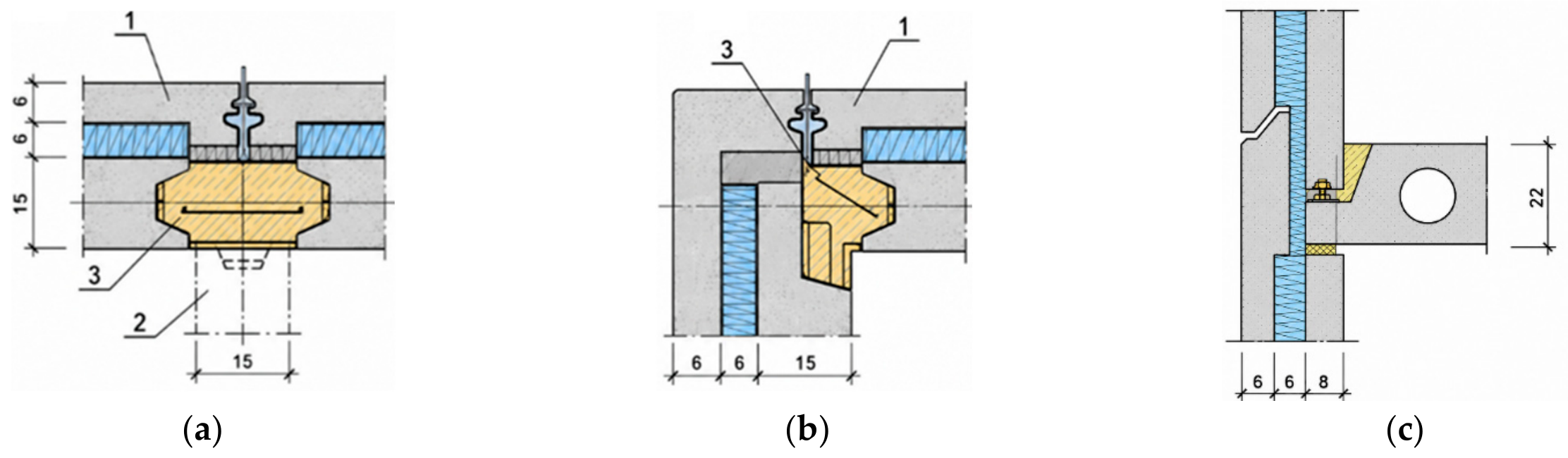
The implementation of the W-70 system during the 1970–1972 period was supported by a comprehensive set of design catalogues covering prefabricated elements, joints and structural connections, standard apartment layouts, building segments and complete buildings, as well as the design documentation for production facilities associated with the manufacture of W-70 components in dedicated House Factories (“Fabryki Domów”) [7], as shown in Figure 2.
Figure 2.
Joints in the W-70 system for load-bearing external walls: (a) vertical joint between end walls; (b) corner joint; (c) horizontal joint of external walls (1—load-bearing wall; 2—internal wall; 3—reinforcement) [7].
The W-70 system was designed for the construction of multi-family residential buildings of:
- Medium-rise buildings (up to 5 storeys),
- Mid-rise buildings (up to 11 storeys), and
- High-rise buildings (up to 16 storeys).
The general design principles for residential buildings constructed using the W-70 system included:
- (a)
- A transverse arrangement of load-bearing walls with spacings of 600, 480, 360, and 240 cm, allowing the orientation of floor slabs to be changed without modifying the design principles of the structural joints;
- (b)
- A standard span of 600 cm for hollow-core floor slabs, with additional spans of 480, 360, and 240 cm;
- (c)
- The possibility of varying the building width (building depth) by using spans of 600 cm and 540 cm, while local setbacks were designed as multiples of the basic module M = 60 cm.
The structural system of the W-70 consisted of standardized prefabricated components developed under both national and regional standardization schemes, including:
- (a)
- Three-layer load-bearing external wall panels, 285.5 cm high, 120, 180, 240, and 300 cm long, and 27 cm thick (6 + 6 + 15 cm). The exterior surface was factory-finished with the final façade texture, while the interior surface was skim-coated and prepared for painting or wallpapering. The panels were delivered complete with factory-installed window frames and window sills.
- (b)
- Large-format non-load-bearing external wall panels (curtain wall panels), 299 cm high, 240, 360, 480, and 600 cm long, and 20 cm thick (6 + 6 + 8 cm).
- (c)
- Load-bearing reinforced concrete internal wall panels, 15 cm thick, 253 cm high, and available in lengths ranging from 120 cm to 600 cm in increments of 60 cm.
- (d)
- Reinforced concrete hollow-core floor slabs (type S), 22 cm thick, 120, 180, and 240 cm wide, and 240, 360, 480, and 600 cm long.
- SYSTEM_2
The Polytech Module System (Polytech MS) [17] is a prefabricated wall panel system. The load-bearing wall panels are manufactured using a modified lightweight thermally insulating Polytech mortar incorporating expanded polystyrene (EPS) regranulate as a lightweight aggregate. The modification of the original Polytech mortar consists of the addition of lightweight aggregate, mineral additives, fibres, and chemical admixtures. As a result, the material has a bulk density of approximately 700 kg/m3 and a compressive strength of 2.76 MPa adopted for design purposes [32].
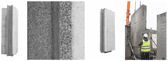
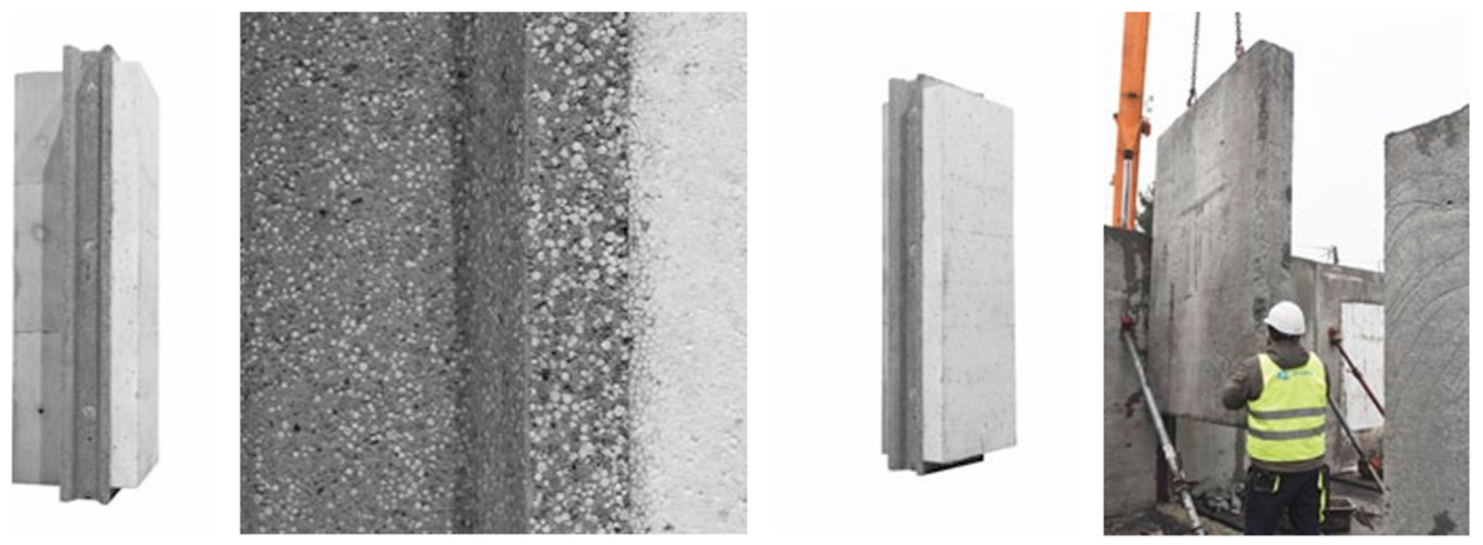
For the numerical analysis, a thermal conductivity of λ = 0.160 W/(m·K) was adopted based on an independent laboratory test report [33]. The thermal conductivity was determined in accordance with EN 12667:2002 [34] using a FOX 600 Heat Flow Meter. The specimens were conditioned to constant mass at (23 ± 2) °C and (50 ± 5) % relative humidity before the measurements. The adopted value of λ = 0.160 W/(m·K) was obtained under these conditioning conditions. The expanded measurement uncertainty reported for the adopted thermal conductivity value was ±0.008 W/(m·K), with a coverage factor of k = 2 and an approximate confidence level of 95%. The measurements were performed at the accredited Laboratory of Building Materials “IZOLACJA”, Łukasiewicz Research Network—Warsaw Institute of Technology, accredited by the Polish Centre for Accreditation (PCA), accreditation No. AB 008 [33]. The thermal insulation layer is 170 mm thick and consists of expanded polystyrene (EPS). The total thickness of the prefabricated styroconcrete external wall panel, including the complete thermal insulation layer, is 470 mm (Figure 3). The thermal transmittance coefficient of the external wall, excluding window and door openings, does not exceed U = 0.15 W/(m2·K).
Figure 3.
Layer configuration of the prefabricated wall panel [17].
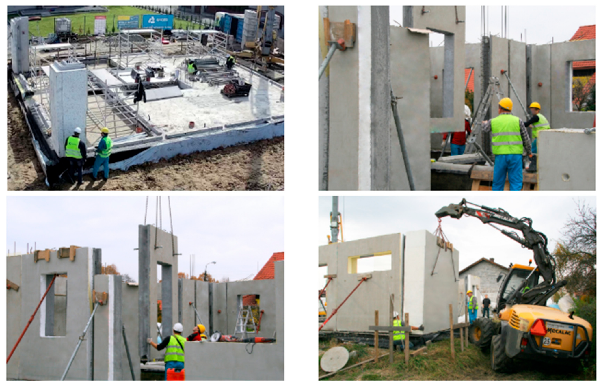
The Polytech MS styroconcrete production technology allows the wall panels to be reinforced according to the structural requirements of each project, including the reinforcement of window and door lintels. Standard prefabricated panels are manufactured in dimensions of 1.20 m × 3.00 m and 2.40 m × 3.00 m. The manufacturing technology also enables the production of wall panels with lengths ranging from 0.30 m to 3.60 m, while the maximum panel height is 3.00 m. The Polytech MS system [17] also includes prefabricated corner elements that enable fast and precise installation (Figure 4).
Figure 4.
Installation of prefabricated wall panels on the construction site [17].
All Polytech MS prefabricated wall panels are installed using either a tower crane or a mobile crane. The corner elements and wall panels are positioned on the building foundation and connected by reinforced concrete connectors located along the vertical edges of each prefabricated element. According to the manufacturer, the Polytech MS system is designed to reduce the occurrence of thermal bridges and to enable rapid assembly. These characteristics were not evaluated within the scope of the present study.
2.2. Physical Quantities Considered in the Analysis
As part of the thermal analysis, the following performance parameters of the building envelope components and their joints were determined:
- Thermal transmittance U;
- Linear thermal transmittance, Ψ;
- Thermal coupling coefficient, L2D;
- Temperature factor at the internal surface, .
- Thermal Transmittance (U-value)
The thermal transmittance, denoted by U, expresses the amount of heat transferred through 1 m2 of a building element (e.g., a wall or roof) when the temperature difference between its two sides is 1 K. The unit of thermal transmittance is W/(m2·K).
A lower U-value indicates better thermal insulation performance of the building element.
where
- —overall thermal transmittance (U-value), calculated in accordance with EN ISO 6946 [35], W/(m2·K);
- —total thermal resistance of the building element, (m2·K)/W.
The total thermal resistance of the building element is calculated as follows (Equation (2)):
where
- —total thermal resistance of the building element, (m2·K)/W;
- —internal surface thermal resistance, (m2·K)/W;
- —external surface thermal resistance, (m2·K)/W;
- —thickness of the i-th layer, m;
- —thermal conductivity of the i-th layer, W/(m·K).
- Linear Thermal Transmittance of a Thermal Bridge
The linear thermal transmittance Ψ is defined as the steady-state heat flow rate per unit length of a thermal bridge divided by the temperature difference between the environments on either side of the building element. This parameter quantifies the additional heat transfer caused by the presence of a thermal bridge, which is not accounted for in the one-dimensional heat transfer model.
In thermal performance calculations, the Ψ-value serves as a correction term that is included in the determination of the overall thermal transmittance of a building element. Its inclusion enables a more accurate assessment of actual heat losses, particularly at the junctions between structural components, where discontinuities in the thermal insulation layer result in multidimensional heat flow.
The overall linear thermal transmittance is calculated using Equation (3) [36]:
where
- —thermal coupling coefficient obtained from a two-dimensional heat transfer analysis of the building component separating the two environments under consideration, W/(m·K);
- —one-dimensional thermal transmittance (U-value) of the j-th building component separating the two environments under consideration, W/(m2·K);
- —length to which the thermal transmittance applies, m;
- —number of one-dimensional building components.
The linear thermal transmittance Ψ quantifies the additional heat losses occurring at thermal bridges as a result of geometric or material discontinuities within the building envelope. It represents the rate of heat transfer per unit length of a thermal bridge.
In accordance with EN ISO 10211 [36], the linear thermal transmittance (Ψ) was determined using the external dimensions of the analysed building elements. The same dimensioning convention was consistently applied to all analysed junctions.
In thermal analysis, a distinction is made between linear thermal bridges, which occur at the junctions between building elements (e.g., wall-to-floor or balcony-to-floor slab connections), and point thermal bridges, which result from localized discontinuities in the thermal insulation layer (e.g., fastening elements such as anchors or mechanical fixings penetrating the insulation).
The value of the Ψ-value depends on the geometry of the structural junction, the thermal properties of the constituent materials, and the thermal transmittance (U-values) of the adjoining building elements. It is determined by means of numerical heat transfer analysis and constitutes an important parameter in the assessment of the energy performance of construction details, particularly for the identification and mitigation of thermal bridges.
- Thermal Coupling Coefficient
The thermal coupling coefficient is defined as the heat flow rate divided by the temperature difference between two environments that are thermally connected by the building element under consideration.
The overall thermal coupling coefficient is calculated using Equation (4) [36]:
where
- —thermal coupling coefficient obtained from the two-dimensional numerical analysis of the analysed structural junction, W/(m·K);
- —heat flow rate through the analysed junction obtained from the numerical simulation, W/m;
- —indoor air temperature, °C;
- —outdoor air temperature, °C.
- Temperature Factor at the Internal Surface ()
The temperature factor at the internal surface, , is an important parameter used to assess the risk of surface condensation and mould growth on building envelope components. It describes the relationship between the internal surface temperature of a building element and the indoor and outdoor air temperatures and is used in thermal analyses in accordance with the relevant standards.
The factor is defined as the ratio of the difference between the internal surface temperature of the building element and the outdoor air temperature to the difference between the indoor and outdoor air temperatures.
The temperature factor at the internal surface, , is calculated using Equation (5) [37]:
where
- —calculated internal surface temperature at the critical location, °C;
- —indoor air temperature, °C;
- —outdoor air temperature, °C.
The minimum required value of the temperature factor at the internal surface, , is intended to prevent building damage resulting from mould growth. Compliance with this requirement is verified according to the following criterion [37]
This limiting value shall be verified at the most critical location within the building structure. According to the Polish Technical Conditions [38] for buildings, the limiting value of the internal surface temperature factor adopted for the assessment of surface condensation risk is . Therefore, this value was used as the acceptance criterion in the present study. Higher values of the factor indicate more favourable thermal conditions at the internal surface of the building element and a lower risk of surface condensation and mould growth.
To prevent mould growth, the monthly average relative humidity at the surface should not exceed the critical relative humidity, which is recommended to be taken as 0.80 (80%). The design procedure begins with the determination of the indoor air humidity. Based on the maximum allowed relative humidity at the surface, the corresponding saturation humidity or water vapour pressure at the surface is then determined. This value is subsequently used to establish the minimum acceptable surface temperature and the required thermal quality of the building envelope, expressed by the temperature factor at the internal surface, , for the specified indoor air temperature.
2.3. Models of Structural Junctions Adopted for the Analysis
Three typical and representative structural junctions were selected for each prefabricated system:
- External corner;
- External wall-to-internal wall junction;
- Floor slab-to-external wall junction.
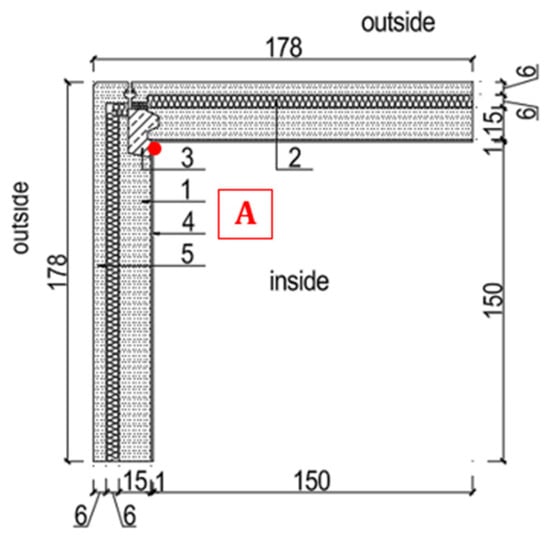
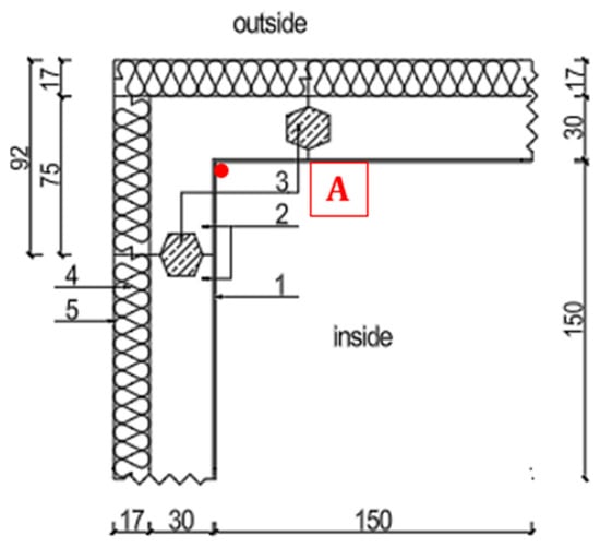
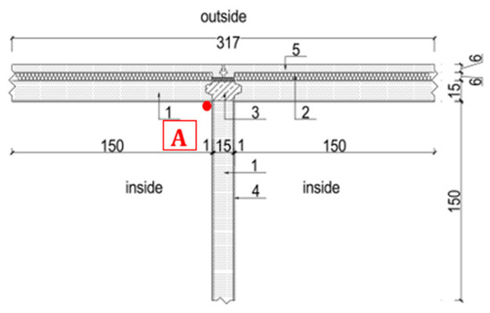
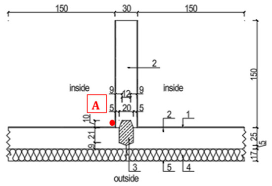
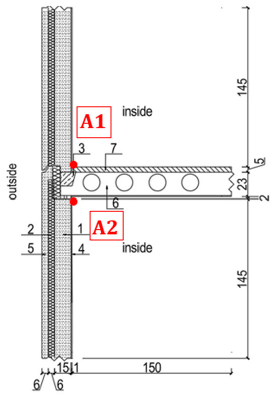
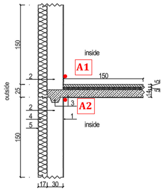
The geometry of the analysed junctions, together with the configuration of their constituent layers, is presented in the corresponding diagrams—Figure 5, Figure 6, Figure 7, Figure 8, Figure 9 and Figure 10. The geometrical models of the analysed structural junctions were developed in accordance with the modelling principles specified in EN ISO 10211, including the adopted external dimension convention used for the calculation of linear thermal transmittance (Ψ). Point A (or A1/A2) shown in Figure 5, Figure 6, Figure 7, Figure 8, Figure 9 and Figure 10 denotes the critical surface location used for the determination of the minimum internal surface temperature (θsi,min) and the evaluation of the internal surface temperature factor (fRsi). The material properties of the individual wall assemblies are summarized in Table 2 and Table 3.
Figure 5.
Detail of the external corner junction for SYSTEM_1. Legend: 1—Reinforced concrete structural layer, 2—Thermal insulation layer, 3—Reinforced concrete key joint, 4—Cement-lime plaster, 5—Reinforced concrete facing layer.
Figure 6.
Detail of the external corner junction for SYSTEM_2. Legend: 1—Cement-lime plaster, 2—Polytech structural layer, 3—Reinforced concrete locking column (key joint), 4—EPS insulation layer fully bonded to the structural layer, 5—Render.
Figure 7.
External wall-to-internal wall junction detail for SYSTEM_1. Legend: 1—Reinforced concrete structural layer, 2—Thermal insulation layer, 3—Reinforced concrete key joint, 4—Cement-lime plaster, 5—Reinforced concrete facing layer.
Figure 8.
External wall-to-internal wall junction detail for SYSTEM_2. Legend: 1—Cement-lime plaster, 2—Polytech structural layer, 3—Reinforced concrete locking column (key joint), 4—EPS insulation layer fully bonded to the structural layer, 5—Render.
Figure 9.
Floor slab-to-external wall junction detail for SYSTEM_1. Legend: 1—Reinforced concrete structural layer, 2—Thermal insulation layer, 3—Reinforced concrete key joint, 4—Cement-lime plaster, 5—Reinforced concrete facing layer, 6—reinforced concrete floor slab, 7—cement screed.
Figure 10.
Floor slab-to-external wall junction detail for SYSTEM_2. Legend: 1—Cement-lime plaster, 2—Polytech structural layer, 3—Reinforced concrete locking column (key joint), 4—EPS insulation layer fully bonded to the structural layer, 5—Render.
Table 2.
Summary of the layers and their properties for Wall W_1 for SYSTEM_1.
Table 3.
Summary of the layers and their properties for Wall W_2 for SYSTEM_2.
2.4. Boundary Conditions
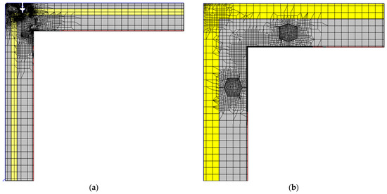
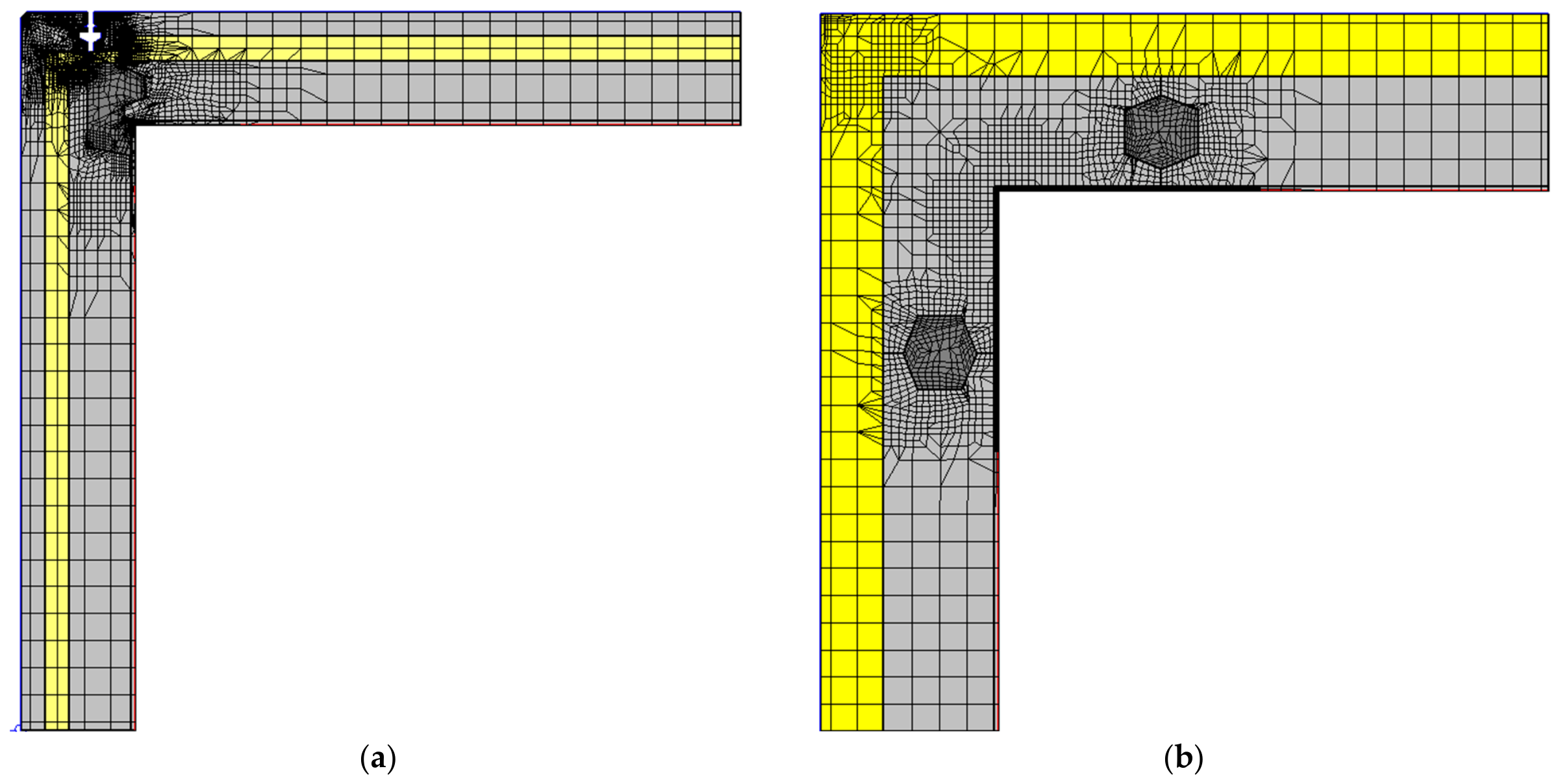
The numerical calculations were performed using THERM 7.6 software, which enables two-dimensional heat transfer analysis of building envelope components based on the finite element method (FEM). The computational settings included a Quad Tree Mesh Parameter of 6, with the Run Error Estimator option enabled, a Maximum % Error Energy Norm of 2%, and a maximum of 20 mesh iterations. The numerical solver was configured with a convergence tolerance of 1 × 10⁻⁶, a relaxation parameter of 1, automatic relaxation parameter adjustment (adjustment step −0.01), and a maximum of 25 iterations. The numerical procedure was verified using Cases 1 and 2 of the benchmark procedure described in Annex A of EN ISO 10211. Case 1 was used to verify the calculated temperature field, whereas Case 2 additionally verified the calculated heat flow. Both benchmark cases satisfied the specified acceptance criteria. Detailed calculation results and comparisons with the reference values are provided in the supplementary validation report. Additionally, all analysed junctions were remodelled using flank lengths satisfying the requirements of EN ISO 10211, and the calculations were repeated. For illustration, the mesh density and local refinement are presented for representative models of both analysed wall systems, showing the adopted mesh configuration in the vicinity of the structural junctions, as shown in Figure 11.
Figure 11.
Finite element mesh density and local refinement for representative junctions of SYSTEM_1 (a) and SYSTEM_2 (b).
The software is widely used for determining temperature distributions and heat flow in complex structural details.
The following boundary conditions were adopted in the analysis:
- Outdoor air temperature: −20 °C;
- Indoor air temperature: +20 °C;
- External surface heat transfer coefficient: hse = 25.0 W/(m2·K) (Rse = 0.04 m2·K/W);
- Internal surface heat transfer coefficient: hsi = 7.69 W/(m2·K) (Rsi = 0.13 m2·K/W), in accordance with EN ISO 6946;
- Internal surface heat transfer coefficient adopted for the determination of θsi,min and the internal surface temperature factor (fRsi): hsi = 4.0 W/(m2·K), (Rsi = 0.25 m2·K/W), in accordance with EN ISO 13788.
- Active boundaries: external boundaries.
The adopted boundary conditions correspond to the standard calculation conditions used in the thermal analysis of building envelope components and provide a reliable basis for evaluating temperature distributions and identifying potential thermal bridges. For the evaluation of the internal surface temperature factor (fRsi), the internal surface thermal resistance Rsi = 0.25 m2K/W was adopted in accordance with EN ISO 13788. The design outdoor temperature of −20 °C was adopted in accordance with PN EN 12831 [39] for the thermal calculations.
3. Results
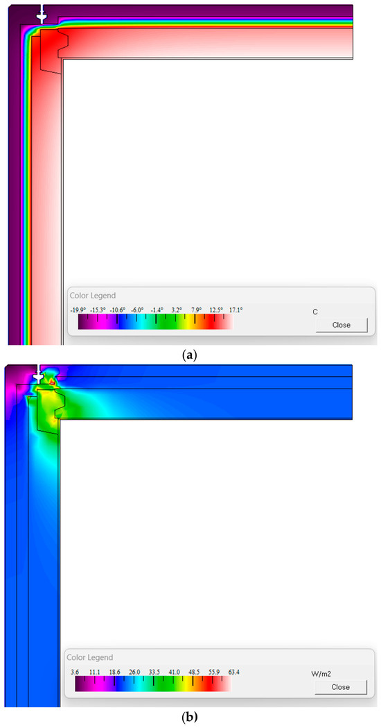
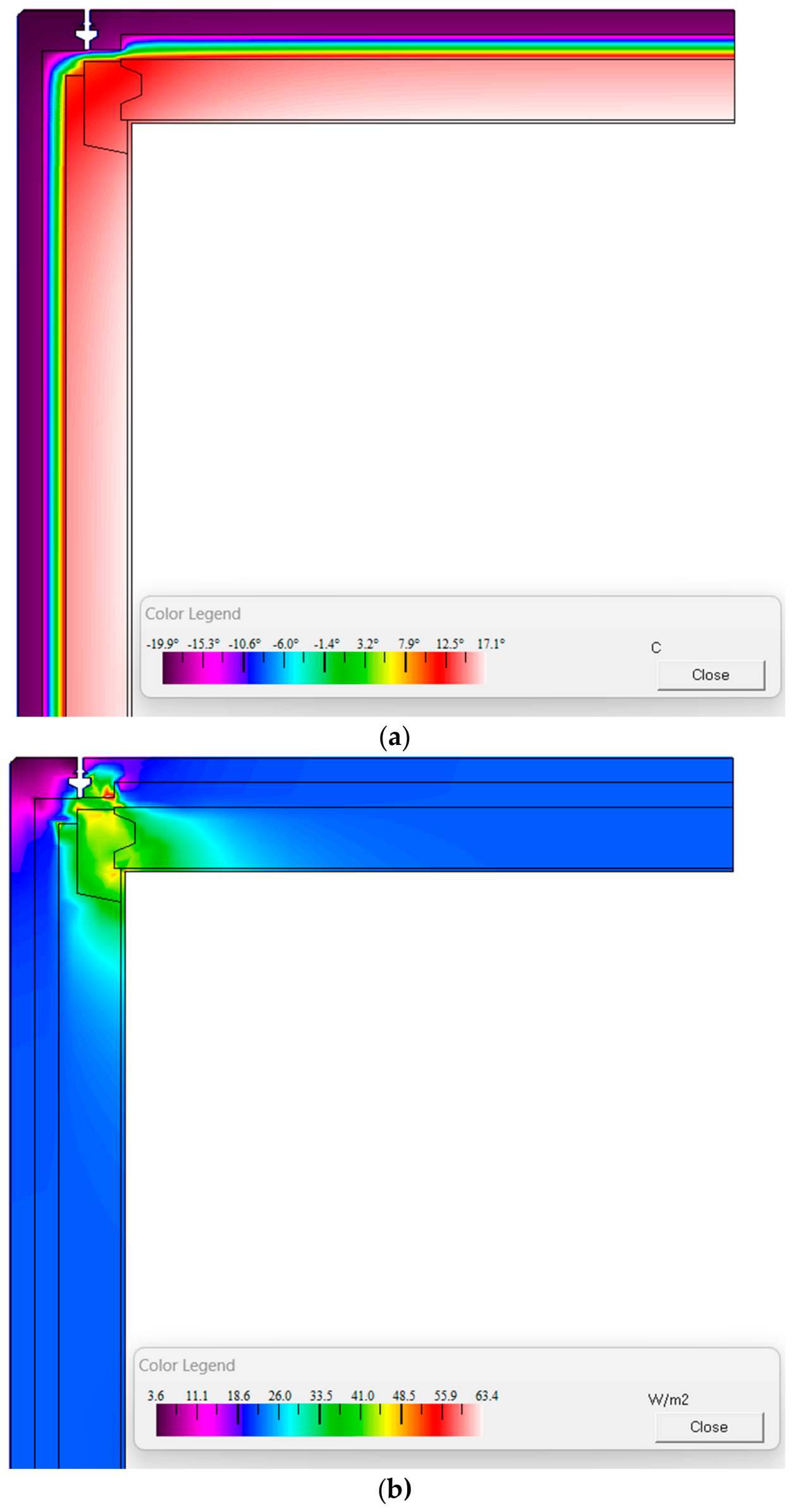
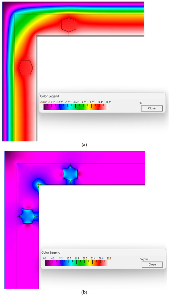
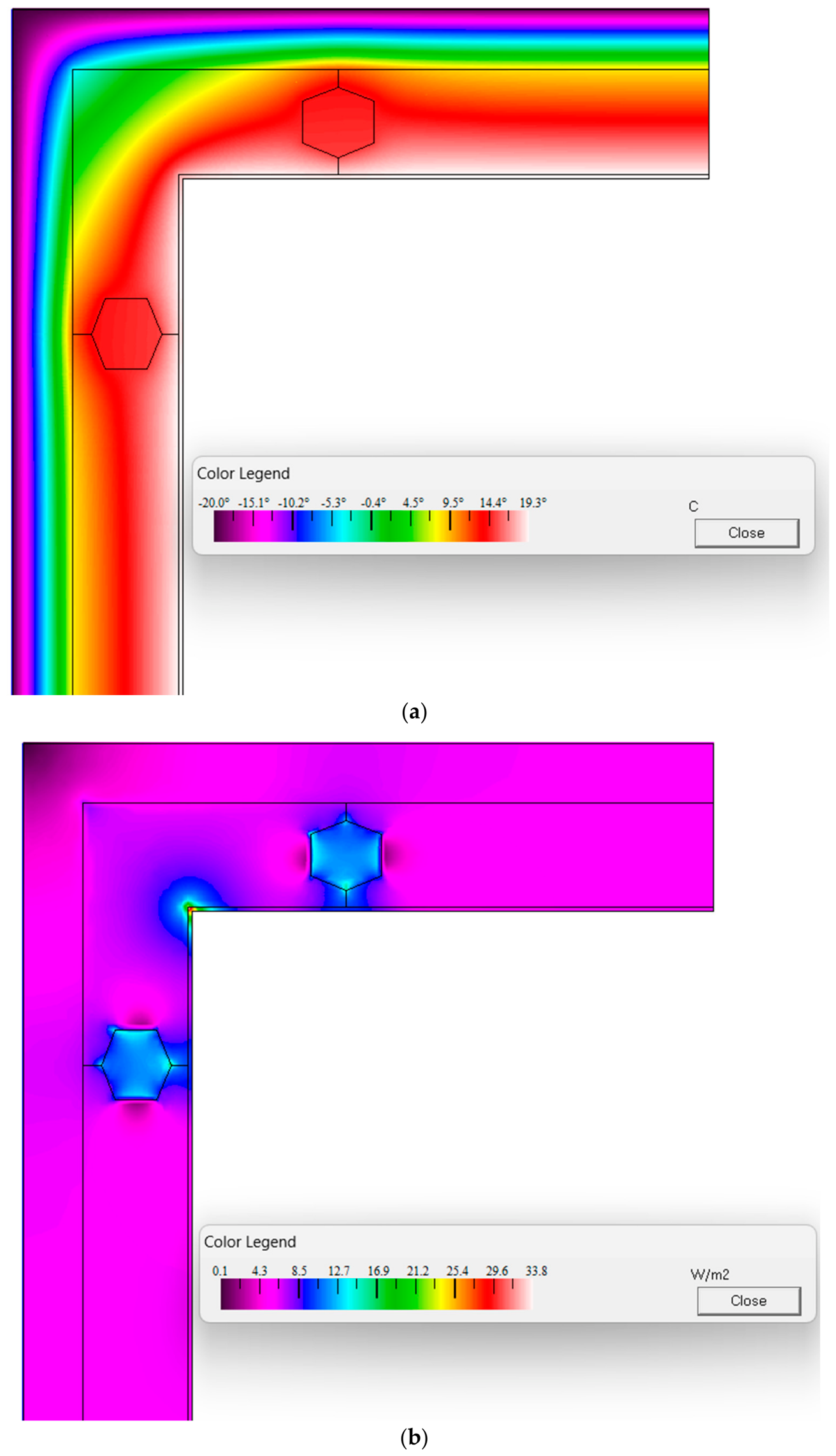
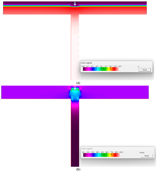
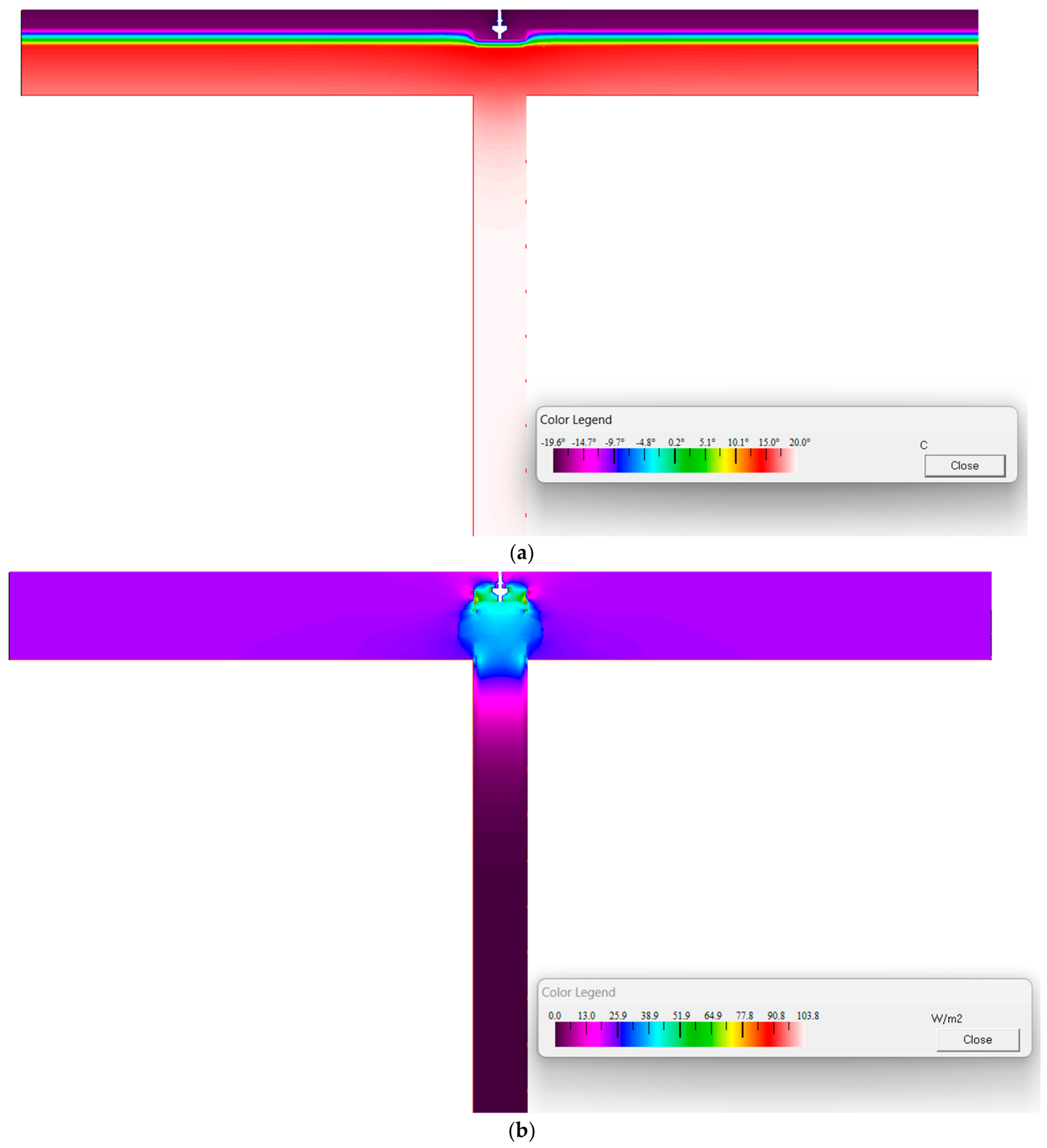
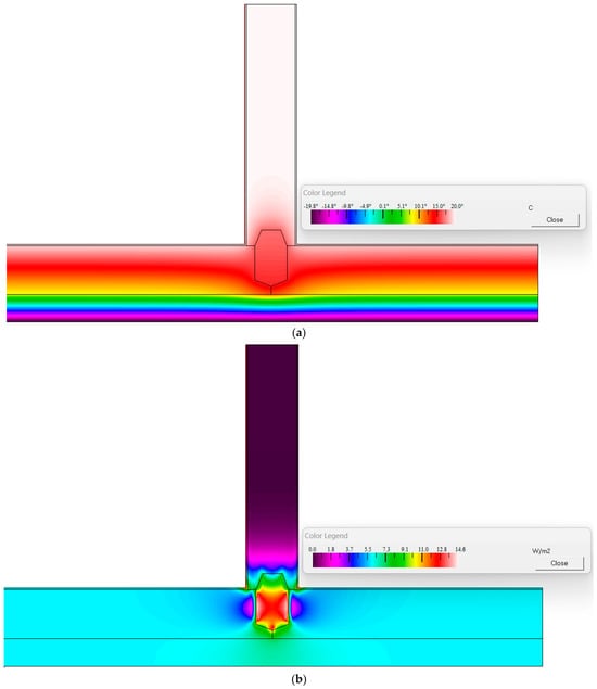
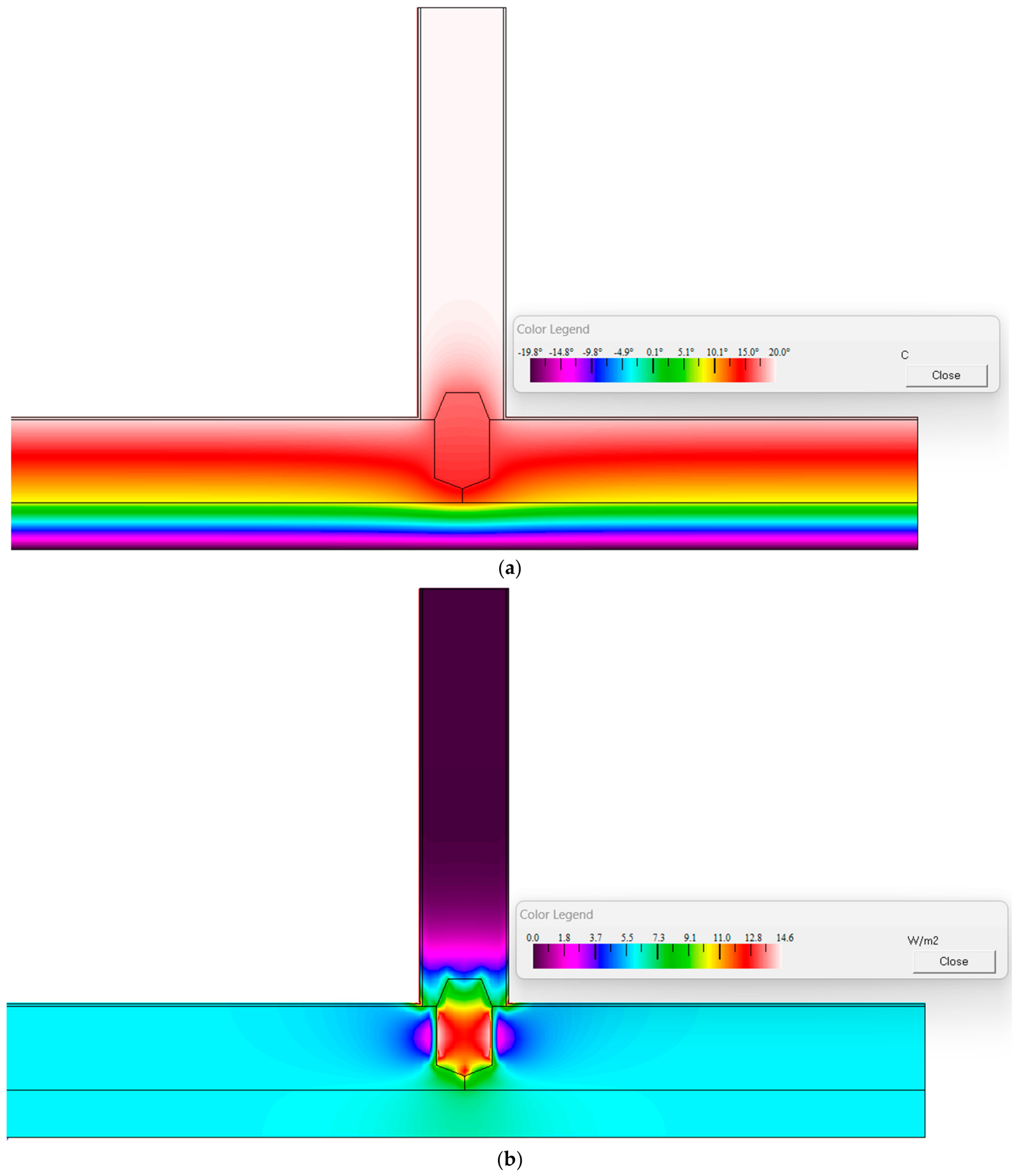
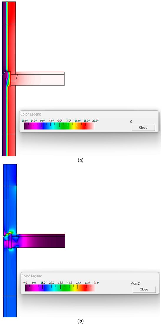
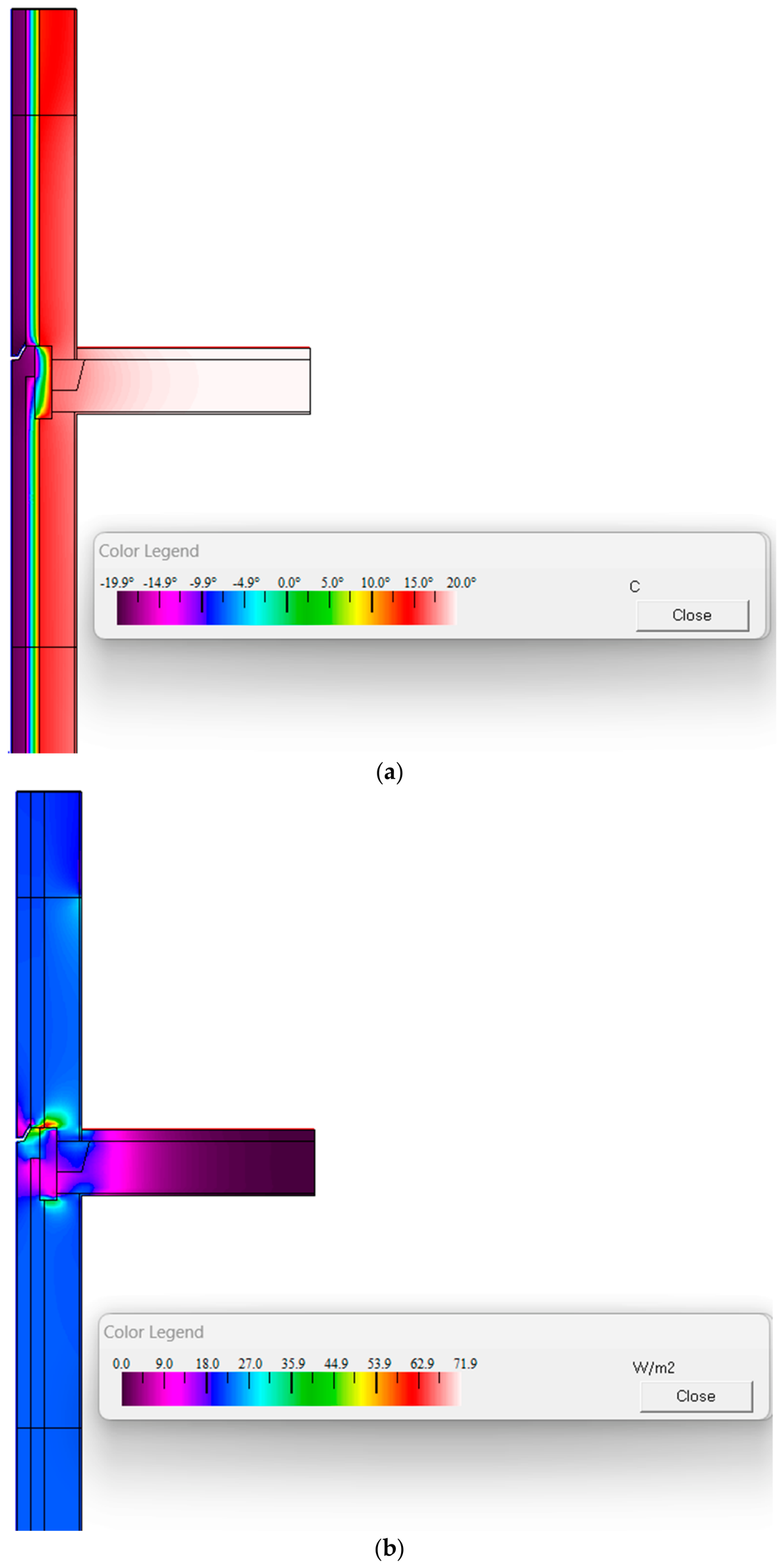
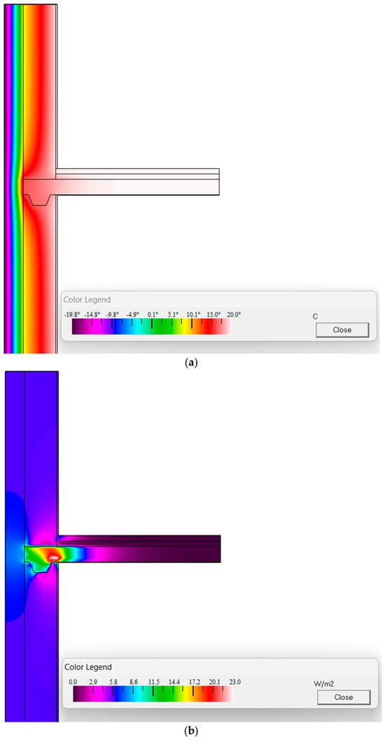
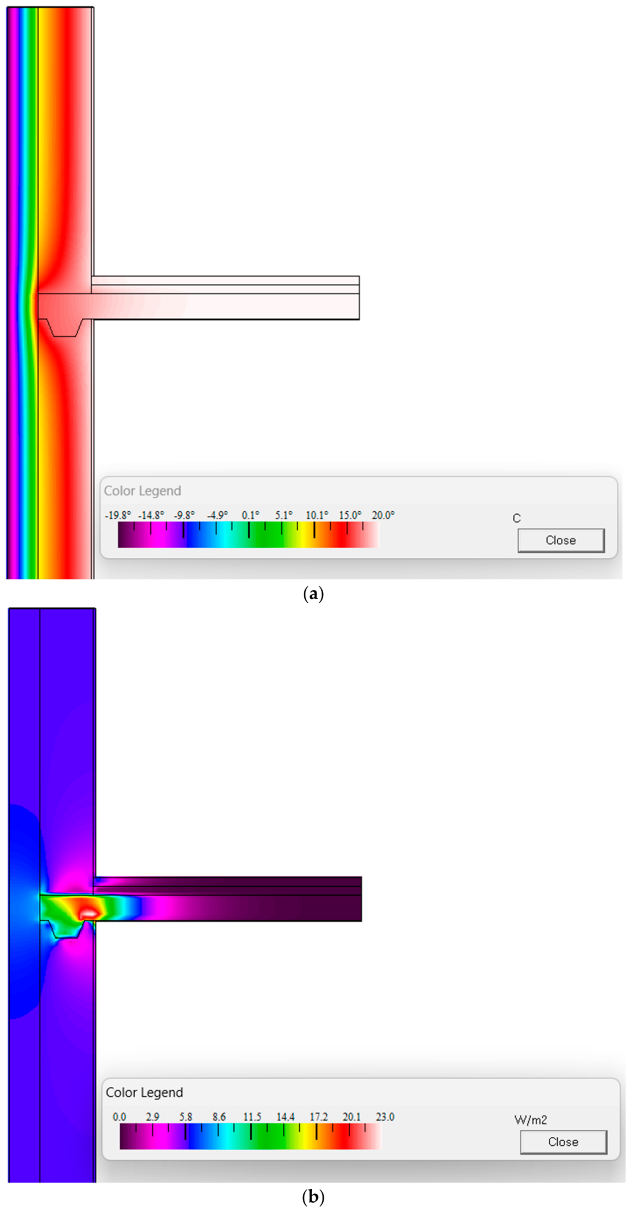
As part of the presentation of the results, a partial temperature distribution within the cross-section of the analysed building element is shown using a colour contour plot, together with the corresponding heat flux density distribution. This form of presentation provides a clear visualization of the isotherm pattern and facilitates the identification of areas with increased heat flow intensity. The results obtained for the all structural junctions are summarized in Figure 12, Figure 13, Figure 14, Figure 15, Figure 16 and Figure 17.
Figure 12.
External corner junction in SYSTEM_1: (a) temperature distribution; (b) heat flux distribution across the building element cross-section.
Figure 13.
External corner junction in SYSTEM_2: (a) temperature distribution; (b) heat flux distribution across the building element cross-sectio.
Figure 14.
External wall-to-internal wall structural junction in SYSTEM_1: (a) temperature distribution; (b) heat flux distribution across the building element cross-section.
Figure 15.
External wall-to-internal wall structural junction in SYSTEM_2: (a) temperature distribution; (b) heat flux distribution across the building element cross-section.
Figure 16.
Floor slab-to-external wall structural junction in SYSTEM_1: (a) temperature distribution; (b) heat flux distribution across the building element cross-section.
Figure 17.
Floor slab-to-external wall structural junction in SYSTEM_2: (a) temperature distribution; (b) heat flux distribution across the building element cross-section.
Table 4 and Table 5 present the results of the numerical calculations of the thermal parameters of the analysed structural junctions, including the external corner, the external wall-to-internal wall junction, and the floor slab-to-external wall junction. The results include the thermal transmittance (U-value), heat flow rate (Φ), thermal coupling coefficient (L2D), linear thermal transmittance (Ψ), minimum internal surface temperature (θsi,min), and the internal surface temperature factor (fRsi). The presented results enable a direct comparison of the thermal performance of junctions constructed using the large-panel building system and the modern prefabricated system.
Table 4.
Summary of the numerical calculation results for the structural junctions—SYSTEM_1.
Table 5.
Summary of the numerical calculation results for the structural junctions—SYSTEM_2.
4. Discussion
The numerical calculations made it possible to compare the thermal performance of two complete prefabricated wall systems representing different construction technologies. The comparison included both the thermal performance of the wall assemblies and the thermal behaviour of three representative structural junctions. Since the analysed systems differ in wall build-up, material properties and insulation thickness, the observed differences reflect the combined influence of these factors together with the analysed junctions.
As expected from the adopted wall build-ups, the calculated wall thermal transmittance was 0.554 W/(m2·K) for SYSTEM_1 and 0.147 W/(m2·K) for SYSTEM_2.
The calculated heat flow (Φ) differed among the analysed junctions. In SYSTEM_1, the values ranged from 71.39 to 74.13 W/m, whereas in SYSTEM_2 they ranged from 19.85 to 20.80 W/m. In SYSTEM_1, the lowest heat flow was obtained at the floor slab–external wall junction (71.39 W/m). In SYSTEM_2, the heat flow values at the external wall–internal wall and floor slab–external wall junctions were 19.85 and 19.87 W/m, respectively. Since this difference is below the adopted 2% numerical tolerance, these two values are not considered sufficiently different to establish a meaningful ranking. The highest heat flow in SYSTEM_1 was obtained at the external wall–internal wall junction (74.13 W/m), while in SYSTEM_2 it was obtained at the external corner (20.80 W/m).
A similar distribution was obtained for the heat flux. In SYSTEM_1, the calculated values ranged from 19.36 to 21.53 W/m2, with the highest value obtained at the external wall–internal wall junction (21.53 W/m2). In SYSTEM_2, the heat flux was 6.02 W/m2 at the external wall–internal wall junction and 6.13 W/m2 at the floor slab–external wall junction. Since the difference between these values is below the adopted 2% numerical tolerance, it is not considered sufficiently large to establish a meaningful ranking. Heat flux represents the local intensity of heat transfer, and its value is influenced by both the thermal properties of the wall assembly and the geometry of the junction.
The values of the thermal coupling coefficient L2D showed the same tendency as the calculated heat flow. In SYSTEM_1, L2D ranged from 1.785 to 1.853 W/(m·K), whereas in SYSTEM_2 it ranged from 0.496 to 0.520 W/(m·K). Since L2D characterises two-dimensional heat transfer through the analysed junction, the obtained values are consistent with the calculated heat flow and describe the thermal behaviour of the analysed details.
A different interpretation is required for the linear thermal transmittance (Ψ). The calculated values ranged from −0.269 to −0.053 W/(m·K) for SYSTEM_1 and from −0.059 to 0.020 W/(m·K) for SYSTEM_2. Consequently, lower Ψ-values were obtained for SYSTEM_1, although the remaining thermal parameters, including heat flow, heat flux, L2D, minimum internal surface temperature and the surface temperature factor (fRsi), indicate higher heat transfer through the analysed junctions. This apparent inconsistency results from the definition of Ψ given in EN ISO 10211. The linear thermal transmittance is determined as the difference between the two-dimensional thermal coupling coefficient L2D and the corresponding one-dimensional reference heat flow. Consequently, its value depends not only on the geometry of the junction but also on the thermal transmittance of the adjoining building elements. Because the analysed wall systems represent complete construction solutions with different wall thermal transmittances, the calculated Ψ-values were interpreted together with the remaining thermal parameters describing the thermal behaviour of the analysed junctions. The interpretation of Ψ also depends on the adopted dimensional convention. In the present study, the calculations were performed using the external dimension system in accordance with EN ISO 10211. Under this convention, negative Ψ-values may occur, particularly for convex external corners, and do not indicate negative heat losses. They result from the adopted reference dimensions used to determine the one-dimensional reference heat flow.
The minimum internal surface temperature showed a similar distribution in both analysed systems. The lowest temperature was recorded at the external corner and reached 11.1 °C in SYSTEM_1 and 16.4 °C in SYSTEM_2. For the external wall–internal wall junction, the minimum temperatures were 15.1 °C and 18.1 °C, respectively. In the floor slab–external wall junction, two critical locations (A1 and A2) were identified. In SYSTEM_1 the temperatures at these points were 15.9 °C and 16.1 °C, whereas in SYSTEM_2 they reached 19.1 °C and 18.0 °C, respectively. These results confirm that the external corner is the junction most susceptible to local surface cooling in both analysed wall systems.
The values of the internal surface temperature factor (fRsi) followed the same distribution as the minimum internal surface temperature. In SYSTEM_1 the calculated values ranged from 0.778 to 0.903, whereas in SYSTEM_2 they ranged from 0.910 to 0.978. According to EN ISO 13788, fRsi is used to assess the risk of surface condensation and mould growth. All analysed junctions fulfilled the criterion fRsi ≥ 0.72, adopted in the Polish Technical Conditions, indicating that the analysed details satisfy the requirements for protection against surface condensation under the assumed steady-state conditions. The lowest values of fRsi were obtained for the external corner, which is consistent with the distribution of the minimum internal surface temperatures.
The results presented in this study refer to complete wall systems rather than to individual structural junctions analysed separately. Therefore, the observed differences reflect the combined influence of wall build-up, material properties, insulation thickness and junction geometry. The results should therefore be interpreted as a comparison of complete wall systems and not as an assessment of the geometry of individual thermal bridges or the influence of recycled EPS considered independently of the analysed wall assembly.
5. Conclusions
The numerical analysis and the comparison of the results obtained for the analysed structural solutions showed differences in the thermal performance of the large-panel W-70 system and the modern prefabricated wall system. The results indicate that the analysed W-70 wall system does not satisfy the current requirements for the thermal insulation performance of external walls. The analysed modern prefabricated wall system was characterised by lower heat flow, lower values of the thermal coupling coefficient (L2D), higher minimum internal surface temperatures and higher values of the internal surface temperature factor (fRsi).
The comparison of the analysed wall systems showed that the applied structural and material solutions influence both the thermal performance of the wall assembly and the thermal behaviour of structural junctions. The numerical analysis showed that the thermal behaviour of the analysed structural junctions cannot be assessed using only the linear thermal transmittance (Ψ). The interpretation of the results should consider the combined analysis of heat flow, heat flux, the thermal coupling coefficient (L2D), the minimum internal surface temperature and the internal surface temperature factor (fRsi).
An important aspect of the analysed prefabricated wall system is the incorporation of recycled EPS regranulate into the structural layer, which is consistent with the principles of material reuse and the circular economy. The use of recycled EPS regranulate may contribute to the utilisation of polymer waste; however, a quantitative assessment of this environmental benefit was beyond the scope of the present study. This approach is consistent with the objectives of Directive 2008/98/EC [40], which promotes the waste hierarchy, including reuse and recycling. The environmental performance of the proposed solution, including its carbon footprint and other life-cycle indicators, was not assessed in the present study and requires a dedicated life cycle assessment (LCA).
In the context of the existing building stock, buildings constructed using the large-panel system require thermal upgrading to meet current thermal insulation requirements. Modern prefabrication technologies provide opportunities to improve the thermal performance of building envelopes through the application of wall systems with lower thermal transmittance.
The results presented in this study should be interpreted as a comparison of complete wall systems rather than as an assessment of individual structural junctions or of the influence of recycled EPS considered separately from the analysed wall assembly. Further research should include a quantitative environmental assessment based on life cycle assessment (LCA), together with analyses performed under different operating conditions and for other structural solutions.
Supplementary Materials
The following supporting information can be downloaded at: https://www.mdpi.com/article/10.3390/en19173969/s1, Figure S1: Benchmark test with the distribution of analytical results at the nodes of the reference model mesh; Figure S2: Analytical model for Case 2 of the reference validation test. 1—concrete; 2—wood; 3—insulation; 4—aluminium; Figure S3: Graphical representation of the computer model of the component for Case 2 of the reference validation test, developed in THERM [author]; Figure S4: Detail of the computer model used in the validation test (Case 2), showing the isotherms and the U-factor calculated by THERM [author]; Table S1: Input data for Case 2 of the reference validation test.; Table S2: Reference temperatures at nodes A–I and total heat flow for Case 2 of the reference validation test; Table S3: Numerical results obtained using THERM for Case 2 of the reference validation test.
Author Contributions
Conceptualization, B.O.-K., B.K., J.K. and M.K.; Methodology, B.O.-K., B.K., J.K. and M.K.; Software, B.O.-K.; Formal analysis, B.O.-K.; Investigation, B.O.-K. and J.K.; Resources, B.O.-K. and M.K.; Data curation, B.O.-K. and J.K.; Writing—original draft, B.O.-K., B.K., J.K. and M.K.; Writing—review & editing, B.O.-K.; Project administration, B.O.-K., B.K. All authors have read and agreed to the published version of the manuscript.
Funding
This research received no external funding.
Data Availability Statement
The original contributions presented in this study are included in the article/Supplementary Material. Further inquiries can be directed to the corresponding author.
Conflicts of Interest
Authors J.K. and M.K. are employees of AKCES BK Sp. z o.o., Czechowice-Dziedzice, Poland. The research was conducted as part of scientific and research collaboration with the company. The authors declare no conflict of interest.
References
- Malazdrewicz, S.; Ostrowski, K.A.; Sadowski, Ł. Large Panel System Technology in the Second Half of the Twentieth Century—Literature Review, Recycling Possibilities and Research Gaps. Buildings 2022, 12, 1822. [Google Scholar] [CrossRef] [Scilit]
- Huuhka, S.; Kaasalainen, T.; Hakanen, J.H.; Lahdensivu, J. Reusing Concrete Panels from Buildings for Building: Potential in Finnish 1970s Mass Housing. Resour. Conserv. Recycl. 2015, 101, 105–121. [Google Scholar] [CrossRef] [Scilit]
- Lawson, R.M.; Ogden, R.G.; Bergin, R. Application of Modular Construction in High-Rise Buildings. J. Archit. Eng. 2012, 18, 148–154. [Google Scholar] [CrossRef] [Scilit]
- Abdelmageed, S.; Zayed, T. A Study of Literature in Modular Integrated Construction—Critical Review and Future Directions. J. Clean. Prod. 2020, 277, 124044. [Google Scholar] [CrossRef] [Scilit]
- Zohourian, M.; Pamidimukkala, A.; Kermanshachi, S.; Almaskati, D. Modular Construction: A Comprehensive Review. Buildings 2025, 15, 2020. [Google Scholar] [CrossRef] [Scilit]
- Kim, S. Prefabricated and Modularized Residential Construction: A Review of Present Status, Opportunities, and Future Challenges. Buildings 2025, 15, 2889. [Google Scholar] [CrossRef] [Scilit]
- Starosolski, W. Konstruowanie Połączeń W Żelbetowych Prefabrykowanych Konstrukcjach Szkieletowych; Wydawnictwo Politechniki Śląskiej: Gliwice, Poland, 1992. [Google Scholar]
- Koncz, T. The Large Panel Building System. PCI J. 1969, 14, 53–63. [Google Scholar] [CrossRef] [Scilit]
- Koncz, T. Assembly Line Speeds Panel Construction for Low Cost Housing. PCI J. 1979, 24, 38–51. [Google Scholar] [CrossRef] [Scilit]
- Zhang, S.; Li, Z.; Li, T.; Yuan, M. A Holistic Literature Review of Building Information Modeling for Prefabricated Construction. J. Civ. Eng. Manag. 2021, 27, 485–499. [Google Scholar] [CrossRef] [Scilit]
- Baduge, S.K.; Thilakarathna, S.; Perera, J.S.; Arashpour, M.; Sharafi, P.; Teodosio, B.; Shringi, A.; Mendis, P. Artificial Intelligence and Smart Vision for Building and Construction 4.0: Machine and Deep Learning Methods and Applications. Autom. Constr. 2022, 141, 104440. [Google Scholar] [CrossRef] [Scilit]
- Wuni, I.Y.; Shen, G.Q. Barriers to the Adoption of Modular Integrated Construction: Systematic Review and Meta-Analysis, Integrated Conceptual Framework, and Strategies. J. Clean. Prod. 2020, 249, 119347. [Google Scholar] [CrossRef] [Scilit]
- KLEBL. Available online: https://www.klebl.de (accessed on 18 July 2026).
- Pekabex. Available online: https://pekabex.com (accessed on 18 July 2026).
- Betard. Available online: https://betard.pl (accessed on 18 July 2026).
- Skonto Prefab. Available online: https://skontoprefab.com (accessed on 18 July 2026).
- Polytech. Available online: https://polytech.info.pl (accessed on 18 July 2026).
- Thomas praefab. Available online: https://www.thomas-next.pl/prefabrykaty/sciany/sciany-z-keramzytobetonu/ (accessed on 18 July 2026).
- Krosbud. Available online: https://www.krosbud.pl/keramzytobeton.html (accessed on 18 July 2026).
- Wolf Haus. Available online: https://wolfhaus.pl (accessed on 18 July 2026).
- Danwood. Available online: https://www.danwood.pl (accessed on 18 July 2026).
- Stora Enso. Available online: https://www.storaenso.com (accessed on 18 July 2026).
- Binderholz. Available online: https://www.binderholz.com (accessed on 18 July 2026).
- Laing O’Rourke. Available online: https://www.laingorourke.com (accessed on 18 July 2026).
- Skonto Prefab Latvia. Available online: https://skontoprefab.lv (accessed on 18 July 2026).
- CIMC Modular Building Systems. Available online: http://www.cimc-mbs.com (accessed on 18 July 2026).
- MOD21. Available online: https://www.mod21.com (accessed on 18 July 2026).
- Xella Group. Available online: https://www.xella.com (accessed on 18 July 2026).
- HPLUSH. Available online: https://www.hplush.com (accessed on 18 July 2026).
- Sah, T.P.; Lacey, A.W.; Hao, H.; Chen, W. Prefabricated concrete sandwich and other lightweight wall panels for sustainable building construction: State-of-the-art review. J. Build. Eng. 2024, 89, 109391. [Google Scholar] [CrossRef] [Scilit]
- Ibrahim, M.M.; William, M.A.; Zidane, I.F.; Hanafy, A.A.; Suárez-López, M.J. Enviro-Economic Assessment of Vegetation–PV Envelope Retrofits for Nearly Zero Energy Buildings in Hot-Humid Climates. Sustainability 2026, 18, 4526. [Google Scholar] [CrossRef] [Scilit]
- Drobiec, Ł. Laboratoryjne Badania Wytrzymałości na Ściskanie i Rozciąganie Próbek Styrobetonu; Katedra Konstrukcji Budowlanych, Wydział Budownictwa, Politechnika Śląska: Gliwice, Poland; Internal laboratory report prepared for AKCES BS Sp. z o.o.: Katowice, Poland, 2026. [Google Scholar]
- Sieć Badawcza Łukasiewicz—Warszawski Instytut Technologiczny, Laboratorium Materiałów Budowlanych “IZOLACJA”. Sprawozdanie nr 237/22/442/M-1/λHFM1 z Badania Właściwości Cieplnych Materiałów i Wyrobów Budowlanych—Określanie Oporu Cieplnego Metodą Czujnika Strumienia Cieplnego—Wyroby o Dużym i Średnim Oporze Cieplnym Według PN-EN 12667:2002; Internal Technical Report prepared for AKCES BK Sp. z o.o.; AKCES BK Sp. z o.o.: Katowice, Poland, 2023. [Google Scholar]
- EN 12667:2002; Thermal Performance of Building Materials and Products—Determination of Thermal Resistance by Means of Guarded Hot Plate and Heat Flow Meter Methods—Products of High and Medium Thermal Resistance. Slovenian Institute for Standardization (SIST): Ljubljana, Slovenia, 2002.
- EN ISO 6946:2017; Building Components and Building Elements—Thermal Resistance and Thermal Transmittance—Calculation Methods. ISO: Geneva, Switzerland, 2017.
- EN ISO 10211:2017; Thermal Bridges in Building Construction—Heat Flows and Surface Temperatures—Detailed Calculations. ISO: Geneva, Switzerland, 2017.
- EN ISO 13788:2012; Hygrothermal Performance of Building Components and Building Elements—Internal Surface Temperature to Avoid Critical Surface Humidity and Interstitial Condensation—Calculation Methods. ISO: Geneva, Switzerland, 2012.
- Regulation of the Minister of Infrastructure of 12 April 2002 on the Technical Conditions to Be Met by Buildings and Their Location; Journal of Laws 2022, Item 1225, as Amended. Warsaw, Poland, 2022. Available online: https://isap.sejm.gov.pl/isap.nsf/download.xsp/WDU20220001225/O/D20221225.pdf (accessed on 18 July 2026).
- PN-EN 12831-1:2017-08; Energy Performance of Buildings—Method for Calculation of the Design Heat Load—Part 1: Space Heating Load, Module M3-3. Polish Committee for Standardization: Warsaw, Poland, 2017.
- European Parliament and Council of the European Union. Directive 2008/98/EC of the European Parliament and of the Council of 19 November 2008 on Waste and Repealing Certain Directives; Official Journal of the European Union: Luxembourg, 2008. [Google Scholar]

Disclaimer/Publisher’s Note: The statements, opinions and data contained in all publications are solely those of the individual author(s) and contributor(s) and not of MDPI and/or the editor(s). MDPI and/or the editor(s) disclaim responsibility for any injury to people or property resulting from any ideas, methods, instructions or products referred to in the content. |
© 2026 by the authors. Licensee MDPI, Basel, Switzerland. This article is an open access article distributed under the terms and conditions of the Creative Commons Attribution (CC BY) license.