


Abstract
Currently, insulation faults in the DC system of photovoltaic (PV) power stations are handled by a full shutdown strategy of inverters, and fault branch localization relies on manual inspection, resulting in low efficiency and poor accuracy, leading to prolonged unplanned outages and substantial power generation losses. This paper proposes an integrated solution combining high-precision insulation monitoring and intelligent fault line selection, which ensures the reliability of line selection criteria through improved measurement accuracy and achieves automatic fault isolation via optimized line selection strategies. The paper analyzes the mathematical essence of the ill-conditioned measurement equations of the traditional bridge method under severe single-pole grounding faults, establishes a dual-channel heteroscedastic noise model, and utilizes the inherent physical constraint that the sum of the positive and negative pole-to-ground voltages always equals the bus voltage to transform the ill-posed inverse problem into an equality-constrained optimal estimation problem, deriving an analytical solution in the sense of constrained least squares. A collaborative monitoring strategy of “balanced bridge monitoring first, unbalanced bridge precision measurement afterward” is proposed. An automatic fault line selection and isolation algorithm based on sequential branch switching is designed, which leverages the operational characteristic that PV systems allow short-term branch interruption, enabling automatic identification and isolation of faulty branches and automatic restoration of non-faulty branches without installing any leakage current sensors. Experimental results show that under severe fault conditions with a single-pole insulation resistance as low as 22 kΩ, the proposed method limits the error to within 5%; the proposed line selection strategy can complete identification and isolation of all faulty branches within at most two rounds of switching.
1. Introduction
The DC side voltage of PV power stations can reach up to 1500 V, and the insulation performance of the DC bus to ground is directly related to equipment safety and system stability [1,2,3,4]. As the DC side voltage level of PV systems increases to 1500 V, the accuracy requirements for DC bus insulation monitoring are becoming increasingly stringent. At the same time, research on the reliability of power electronic converter topologies in medium- and high-voltage DC applications is also being continuously deepened [5]. The reliability issues of PV systems not only involve switching device faults inside power converters [6], but also the degradation of DC bus insulation performance to ground—once a grounding fault occurs in the latter, it often leads to the shutdown of the entire inverter. Currently, insulation faults in the DC system are handled by a full shutdown strategy of inverters, and fault branch localization relies on manual inspection, resulting in low efficiency and poor accuracy, leading to prolonged unplanned outages and substantial power generation losses. Soft faults that “appear on rainy days and self-heal on sunny days” cannot be promptly addressed due to adverse weather, posing safety hazards. Long-term reliability studies of PV modules indicate that the failure rate of modules increases significantly after 10–12 years of operation, and faults often exhibit environmental dependence [7]. According to domestic operational statistics, the average annual incidence of DC grounding faults in PV station inverters is 5–10 times per 100 MW, and the fault probability increases with the operation time of the station. Manual fault inspection takes an average of 8–12 h. For some soft faults, long-term tracking and monitoring are required, extending the troubleshooting period and resulting in greater energy losses.
Detection of DC bus grounding faults relies on the measurement of insulation resistance. Currently, inverters generally adopt the bridge method for insulation resistance measurement. The existing technical standards impose quite lenient requirements on the measurement accuracy of insulation resistance. According to DL/T 1392-2014 “Technical Specifications for Insulation Monitoring Devices of DC Power Supply Systems” [8], when the single-pole-to-ground voltage is below 10% of the rated voltage, the standard does not impose accuracy requirements; GB/T 34131-2023 “Battery Management System for Electric Energy Storage” only requires an insulation resistance detection error of 20% or 30% [9]. The essence of the traditional bridge method for measuring insulation resistance is to indirectly infer the resistance value from voltage measurements; the accuracy of insulation resistance depends on the accuracy of voltage measurement. However, when insulation severely deteriorates, the voltage of one pole to ground attenuates sharply to a weak signal level, and the measurement error is magnified by the denominator term, causing the calculation result to be completely distorted.
To overcome this bottleneck, domestic and international scholars have conducted extensive research from various perspectives. At the level of device design and method improvement, Yang et al. proposed an improved insulation detection method based on the bridge balance principle and, combined with DC leakage current sensors, achieved detection of bus and branch insulation conditions as well as rapid localization of faulty branches [1], but this method still relies on the deployment of a large number of sensors and fails to solve the problems of complex sensor installation and insufficient accuracy in weak signal detection. Wang et al. proposed an insulation detection method combining the bridge detection method and the differential current detection method, effectively eliminating common-mode voltage fluctuations in the bridge method, but this method still requires differential current sensors on each branch, resulting in high system complexity [10]. In terms of optimizing the bridge method itself, He et al. combined the unbalanced bridge with the balanced bridge to simultaneously detect symmetric and asymmetric DC grounding and improve detection sensitivity [11], but did not address automatic fault line selection and isolation. Hu et al. also combined the unbalanced bridge and balanced bridge to design an online insulation monitoring device for the DC bus of PV power stations and made optimization improvements from an engineering perspective [12], but their research remains focused on bus-level insulation monitoring and does not extend to automatic identification and isolation of branch-level faults. Wu et al. designed three insulation detection schemes for PV arrays, namely an improved balanced bridge method, an improved DC method, and an improved low-frequency detection method, and verified their effectiveness through experiments [13], but all three methods require external signals or additional detection loops, increasing system complexity.
At the theoretical analysis level, Du conducted systematic unified modeling and differentiated analysis of the bridge method and the injection method, revealing the respective applicable scopes and limitations of the two methods [14], but did not propose a fundamental solution to the accuracy degradation of the bridge method under extreme conditions. Cheng et al. theoretically analyzed the insulation resistance calculation method of the bridge method, studied online insulation monitoring and its implementation methods for DC systems, and provided corresponding measurement and implementation schemes [15]. However, that research still focused on optimizing circuit parameters and monitoring methods and failed to reveal the deeper mathematical essence of the ill-conditioned measurement equations under single-pole severe grounding. Overall, most existing improvement schemes focus on circuit topology optimization, detection method improvements, or hardware parameter adjustments, lacking systematic theoretical understanding of the mathematical nature of measurement accuracy degradation.
In terms of fault line selection, the current mainstream solution is to install leakage current sensors at the point where lines converge into the DC bus. However, this method requires a large number of sensors and is inconvenient to install, especially in floating PV systems where difficulties are particularly prominent. More importantly, sensors find it difficult to perceive weak leakage currents, and measurement accuracy is generally insufficient. Online monitoring using the injection method also has many drawbacks, such as the injected signal being affected by distributed capacitance, introducing voltage ripple into the DC bus, affecting power quality, and potentially interfering with sensitive equipment such as inverters. Currently, the branch strings of PV station inverters that converge into the DC bus mostly use manual switches; even if the line selection device identifies the faulty branch, it cannot automatically disconnect it, still causing inverter outage. Existing research mostly focuses on a single insulation monitoring method or a single line selection method, lacking a systematic solution that organically integrates high-precision monitoring and intelligent line selection and isolation.
This paper re-analyzes the intrinsic reasons for the degradation of measurement accuracy of the traditional bridge method under severe single-pole grounding. Theoretical analysis shows that when the voltage of one pole to ground approaches zero, the condition number of the measurement equation tends to infinity, and tiny voltage measurement errors can cause the calculated insulation resistance to deviate severely from the true value—this is a typical ill-posed inverse problem. To mitigate this ill-posedness, this paper utilizes the inherent physical constraint that the sum of the positive and negative pole-to-ground voltages always equals the bus voltage, transforming the traditional ill-posed solution problem into an equality-constrained optimal estimation problem, deriving an analytical solution in the sense of constrained least squares, and achieving adaptive reconstruction of weak voltage signals, thereby greatly improving the measurement accuracy of insulation resistance under severe single-pole faults. On this basis, a collaborative monitoring strategy combining the balanced bridge and unbalanced bridge is further designed, where the balanced bridge undertakes continuous monitoring duties and the unbalanced bridge is only engaged for precision measurement upon detection of insulation anomalies, thus ensuring real-time monitoring while avoiding system disturbances caused by frequent relay switching. Finally, the high-precision insulation measurement values are combined with a sequential branch switching algorithm to propose a fault automatic line selection and isolation scheme that does not require leakage current sensors, leveraging the operational characteristic that PV systems allow short-term branch interruption to achieve automatic identification of faulty branches and automatic restoration of non-faulty branches.
2. Ill-Posed Problem of Insulation Resistance Measurement
2.1. Measurement Equations and Error Analysis of the Balanced Bridge Method
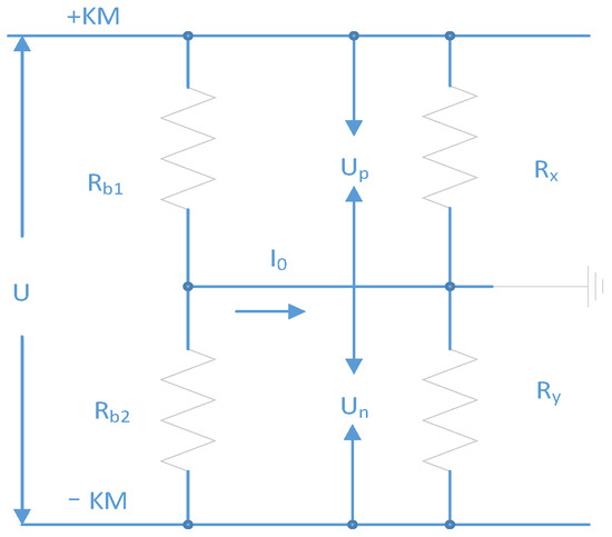
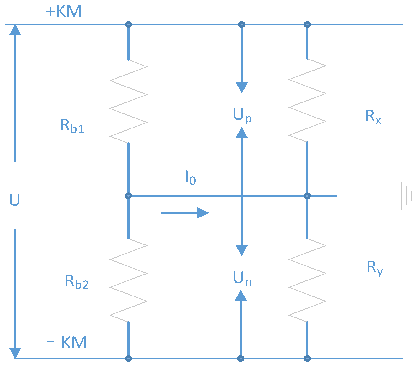
As shown in Figure 1, in the balanced bridge method measurement principle, , are standard balanced bridge resistors (typically = = ), and , are the insulation resistances of the positive and negative poles to ground, respectively. During normal operation, the bridge is balanced, with . When a single-pole insulation degradation occurs, taking positive pole grounding as an example, it can be derived that:
Figure 1.
Balanced bridge method measurement principle.
From Equation (1), the insulation resistance is uniquely determined by the voltage ratio . When the positive pole is severely grounded, , then . At this time, because is in the denominator, a very small error in is drastically amplified, leading to a drastic amplification of the error in .
2.2. Ill-Posed Inverse Problem Analysis of Balanced Bridge Single-Pole Severe Short Circuit
The previous section analyzed the reasons for measurement distortion from the intuitive perspective of error propagation. This section places insulation resistance measurement under the theoretical framework of inverse problems to precisely characterize the fundamental reason why “input errors tend to infinity” causes “the solution does not depend continuously on the data” [16,17,18]. The measurement of insulation resistance can be abstracted as: retrieving the unknown parameter from the observations . The relationship between observations and unknown parameters is given by the bridge equations, which can be written as:
where G is a nonlinear mapping, and is measurement noise. When (severe positive pole grounding), the condition number of the Jacobian matrix of mapping G satisfies . At this point, a small perturbation in the measurement noise can lead to a huge deviation in the inversion result . This is exactly an ill-posed inverse problem in the Hadamard sense—the solution does not depend continuously on the observed data.
The physical origin of this ill-posedness is: when the insulation resistance of the positive pole to ground approaches zero, the amplitude of attenuates sharply to a level far below the effective resolution of the measurement system. At this time, the observed value of is almost entirely dominated by noise (including quantization noise, thermal noise, zero drift, etc.), useful information is submerged, and the measurement resistance error is drastically amplified.
2.3. Error Propagation Characteristics of the Unbalanced Bridge Method
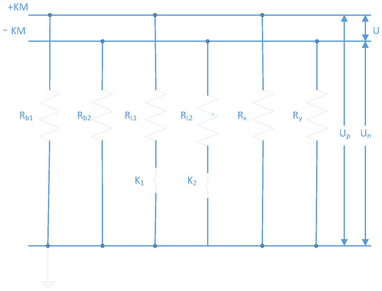
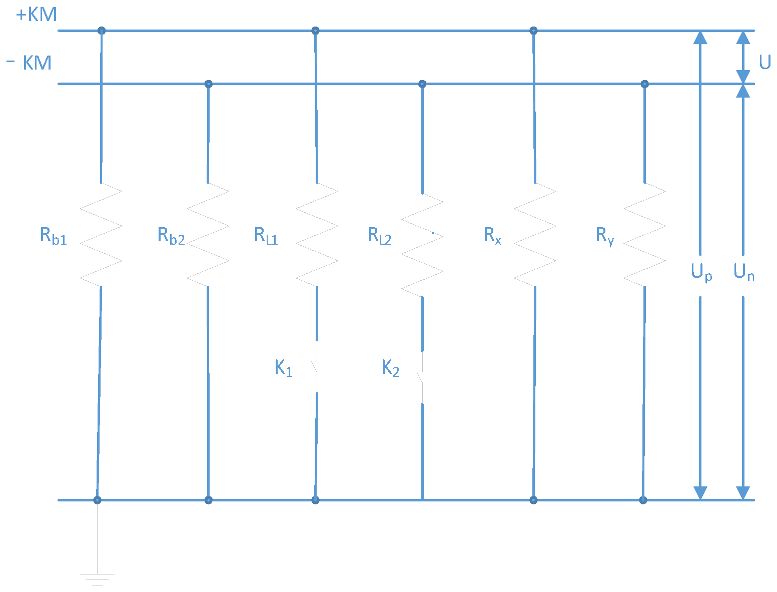
As shown in Figure 2, the unbalanced bridge method breaks the symmetry by switching additional resistors , on the basis of the balanced bridge. When K1 is closed:
Figure 2.
Unbalanced bridge method measurement principle.
In Equation (3), is the positive pole-to-ground voltage when K1 is closed and K2 is open, and is the negative pole-to-ground voltage under the same condition. When K2 is closed:
In Equation (4), is the positive pole-to-ground voltage when K2 is closed and K1 is open, and is the negative pole-to-ground voltage under the same condition. Combining Equations (3) and (4) yields [19]:
It can be seen that the calculation results of the unbalanced bridge method also depend on the voltage ratios and . When the voltage of one pole approaches zero, the corresponding voltage ratio tends to infinity, and the ill-posedness problem also exists. Therefore, whether it is the balanced bridge method or the unbalanced bridge method, the fundamental bottleneck of measurement accuracy lies in the ill-posed inverse problem itself, rather than the specific circuit topology. Hardware adjustments alone cannot fundamentally solve the problem; breakthroughs must be sought at the level of signal processing and estimation theory.
3. Measurement Reconstruction Method Based on Voltage Redundancy Constraints
The analysis in the previous section shows that the root cause of ill-posedness is not a defect in circuit topology, but that the effective signal of one channel is completely overwhelmed by noise during single-pole grounding. Therefore, this section does not attempt to enhance weak signals through hardware improvements, but instead, from the perspective of signal processing, utilizes the inherent but underutilized physical constraint in DC bus voltage—the sum of the positive and negative pole-to-ground voltages always equals the bus voltage—to reconstruct the weak signal submerged by noise. The introduction of this physical constraint fundamentally avoids the error amplification problem caused by direct measurement of weak signals.
3.1. Dual-Channel Heteroscedastic Noise Model
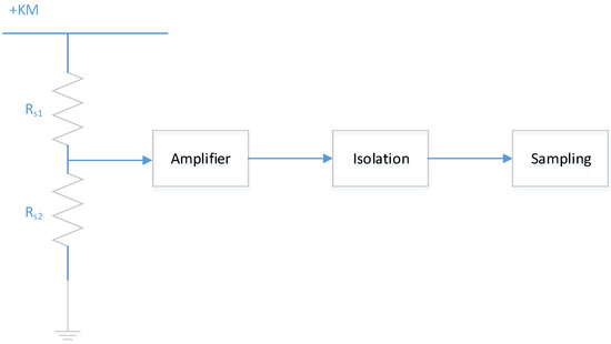
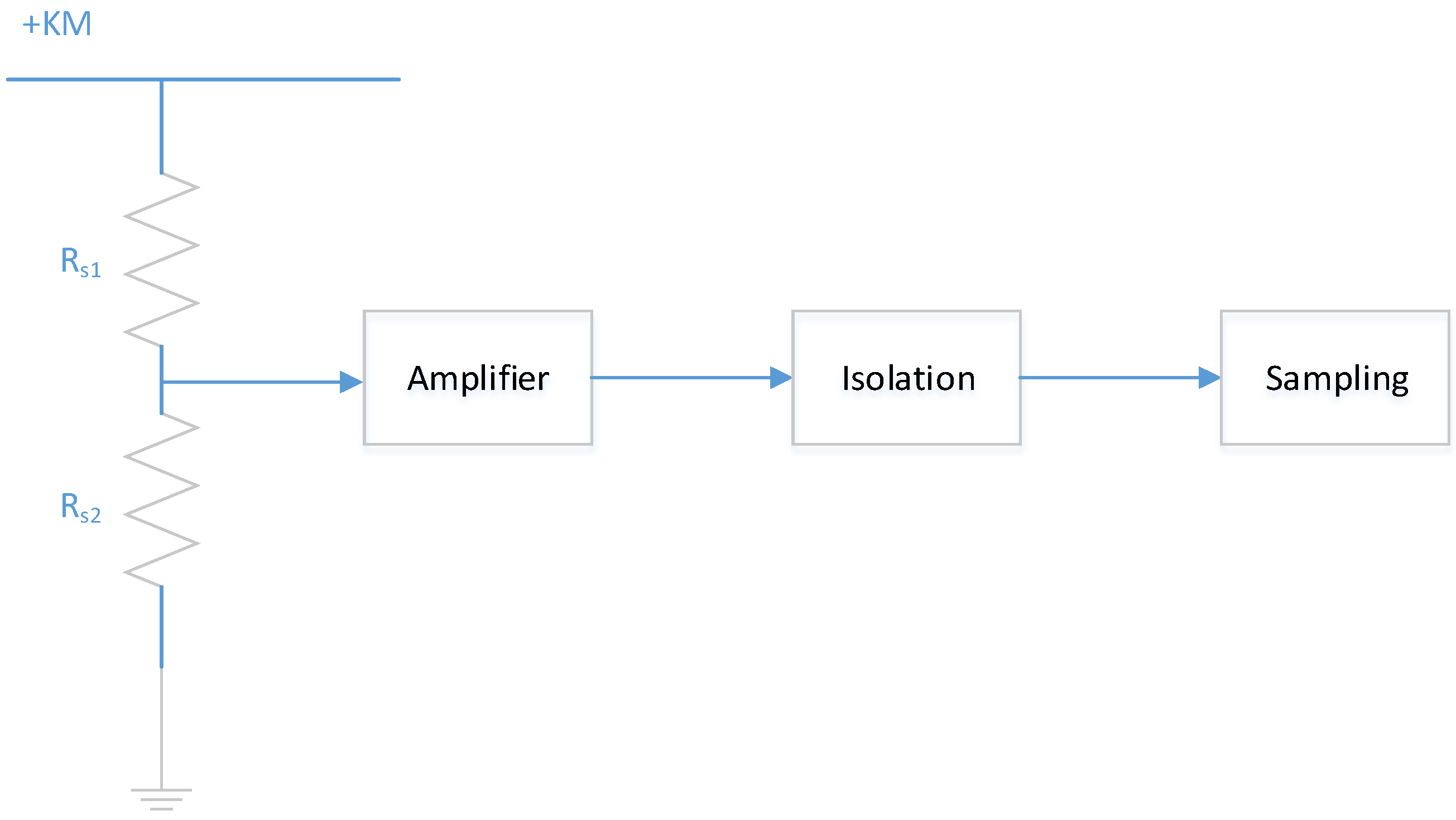
A typical measurement circuit for bus voltage is shown in Figure 3. and form a sampling resistor divider network; the voltage across is sent to AD sampling after isolation amplification. Due to the insulation requirements of the DC system, the sampling resistors have large resistance values (typically = 1000 , = 5.6 ), resulting in extremely weak sampling currents.
Figure 3.
Principle diagram of busbar voltage measurement.
Let the observed values of the positive pole-to-ground voltage measurement channel and the negative pole-to-ground voltage measurement channel be:
where and are measurement errors. It should be emphasized that the statistical characteristics of and are closely related to the signal amplitude—in DC bus voltage measurement, when the signal amplitude decreases, the signal-to-noise ratio deteriorates sharply, and the variance of the error increases. Therefore, a heteroscedastic noise model can be used to describe the statistical properties of measurement errors [20]:
where is a monotonically decreasing function of —the weaker the signal, the larger the variance. In practical systems, a zero-drift voltage of tens of volts can still be observed when the input signal is zero, which is an extreme manifestation of the heteroscedastic characteristic.
3.2. Voltage Redundancy Constraint
There exists an inherent physical constraint between the positive and negative pole-to-ground voltages of the DC bus that does not depend on the insulation state:
where is the bus voltage between the positive and negative poles. During normal system operation, remains constant (or changes slowly) and can be obtained with high-precision measurement. This constraint means that the two observed quantities and are not independent but satisfy a strict linear coupling relationship—once one is determined, the other is uniquely determined.
From the perspective of observability theory, traditional methods treat and as two independent observations processed separately, ignoring the redundant information contained in Equation (8). When the system is in a normal state (), both channels operate in high signal-to-noise ratio regions, and the role of information redundancy is not significant. However, when a severe single-pole grounding occurs (e.g., ), the effective information of the channel is submerged by noise, but the signal of the channel is enhanced instead (). At this time, the constraint of Equation (8) actually provides a bridge for transferring information from the high-precision channel to the low-precision channel.
3.3. Optimal Fusion Estimation Under Equality Constraints
Using the redundancy constraint of Equation (8), the insulation resistance measurement problem can be reconstructed as the following equality-constrained optimal estimation problem [21]:
This optimization problem is formally a weighted least squares estimation with linear equality constraints, where and are the noise variances of the two measurement channels. The physical meaning of this optimization problem is: under the premise of satisfying the physical constraint, find the optimal estimate closest to the original observations, while assigning greater weight to the higher-precision channel.
Construct the Lagrange function
Setting the partial derivatives to zero yields the analytical solution:
From Equations (11) and (12), it can be seen that the optimal estimate is a weighted average of the direct measured value and the value inferred from the constraint, with weights determined by the relative accuracies of the two channels.
When the system is in normal operation, , Equation (11) simplifies to , and the estimate is essentially equal to the measured value, not changing the original measurement result.
When a severe positive pole grounding occurs, , at this time, (the variance of the small-signal channel is much larger than that of the large-signal channel). In Equation (11), the weight of is , while the weight of is . Thus:
That is, the optimal estimate automatically abandons the unreliable direct measured value and instead adopts the high-precision constraint-inferred value. It is worth noting that this switching is a soft switch—naturally realized by the continuous change in the variance ratio, rather than relying on a manually set threshold (such as 150%), thereby eliminating engineering empirical parameters and achieving seamless switching of the algorithm.
4. Intelligent Line Selection and Automatic Isolation Method Based on Sequential Branch Switching
4.1. Shortcomings of Existing Line Selection Methods
Currently, fault line selection in PV power stations faces multiple difficulties. The leakage current sensor scheme requires installing a large number of sensors at the line convergence points into the bus, which is extremely inconvenient, especially in scenarios such as floating PV systems; sensors have difficulty detecting weak leakage currents, and measurement accuracy is generally insufficient, easily leading to system maloperation. Smart sensor solutions adopted to improve accuracy can avoid long-distance transmission of small analog signals but require a processor and power supply for each sensor, further increasing system complexity. The injection method injects low-frequency AC or variable-frequency signals into the DC bus and detects signal components via branch transformers for line selection. However, PV station cables are long and have significant capacitance to ground; the leakage current generated by the injected signal through the capacitive path superimposes on the resistive current of the fault resistance, severely interfering with detection results, especially under large transition resistance conditions, easily causing misjudgment or missing detection. At the same time, the injected signal introduces voltage ripple into the DC bus, affecting power quality and potentially interfering with sensitive equipment such as inverters. Handheld injection instruments require the inverter to be shut down and branches to be disconnected one by one for troubleshooting, causing prolonged outages. For soft faults that “appear on rainy days and disappear on sunny days,” the fault disappears after power-off, making it difficult to capture the actual operating condition. Furthermore, none of the existing schemes are equipped with automatic switches; even if the faulty branch is identified, it cannot be automatically disconnected, still requiring on-site manual operation, prolonging outage time. Therefore, existing line selection methods suffer from high system complexity, insufficient accuracy, and inability to achieve automatic fault isolation.
4.2. Collaborative Monitoring Strategy of Balanced and Unbalanced Bridges
The balanced bridge method can achieve real-time monitoring with fast response, but it cannot detect simultaneous equal-value insulation degradation of both positive and negative poles. The unbalanced bridge method can measure symmetrical faults but requires frequent relay switching, causing DC voltage fluctuations. If operating in the unbalanced bridge mode for a long time, frequent relay switching not only affects system stability but also shortens equipment life.
This paper proposes a collaborative strategy of “balanced bridge monitoring first, unbalanced bridge precision measurement afterward.” During normal system operation, the balanced bridge mode is used for monitoring, refreshing insulation resistance values in real time, while the bus voltage remains stable without disturbance. Once the balanced bridge detects that the insulation resistance falls below the preset threshold, it automatically switches to the unbalanced bridge mode to obtain precise measurement values. After fault clearance, it automatically returns to the balanced bridge mode to avoid frequent relay switching.
The balanced bridge acts as a “sentry” for uninterrupted monitoring, while the unbalanced bridge serves as a “precision tool” only when necessary; the two complement each other, ensuring real-time monitoring while avoiding unnecessary system disturbances. In actual operation, it is almost impossible for the DC system to experience simultaneous symmetrical insulation damage on both poles. Even if a symmetrical insulation fault occurs, it must inevitably develop from an asymmetric to a symmetric state. The balanced bridge method has a refresh cycle on the order of milliseconds; once an anomaly is detected, switching to the unbalanced bridge occurs immediately, and the response speed is sufficient to handle the situation.
4.3. Principle of Intelligent Line Selection
Assume that a total of parallel branches are connected to the DC bus. Define the fault state of the -th branch as , where indicates that the branch has a grounding fault, and indicates normal insulation of the branch.
The parallel model of bus insulation resistance has been widely used in DC system insulation monitoring research [22,23]. The idea of calculating the insulation resistance of each branch after sequential switching to locate the faulty branch proposed in this paper has certain similarity in research objectives to the fault detection, classification, and localization study conducted by Mehmood et al. for PV arrays [24]. Li established a mathematical model for insulation resistance determination based on the unbalanced bridge and developed a fault point localization device on this basis [25]. Furthermore, Feng et al. proposed a distributed-centralized online insulation monitoring system and line selection technology suitable for DC power supply systems [26]. Building upon the above research, this paper further integrates high-precision insulation measurement with sequential switching decisions to achieve automatic fault line selection and isolation without the need for leakage current sensors. The bus-to-ground insulation resistance is the parallel combination of the insulation resistances of all branches:
where is the bus’s own (excluding branches) insulation resistance to ground, and is the insulation resistance to ground of the -th branch. For a faulty branch, decreases to the fault resistance value ; for a normal branch, remains at a relatively large value within the normal operating range, (typically above several megohms). Therefore, the measured value of directly reflects the overall insulation condition of all branches currently in operation.
It is particularly worth pointing out that in the formula is not a rough estimate from traditional methods, but a high-precision measurement value output by the optimal reconstruction algorithm described in Section 3. This accuracy advantage translates directly into the reliability of line selection criteria: under an extreme fault of , a error in traditional methods might cause normal branches to be misjudged as faulty (insufficient criterion margin), whereas the error in this paper provides ample margin for threshold comparison, ensuring every switching judgment is authentic and believable.
Define the switching state of branch as , where indicates that the branch is in operation, and indicates that the branch is disconnected. Then, under any switching combination , the bus insulation resistance is:
Define the “normal state threshold” of bus insulation resistance as (typically set according to the system’s insulation level). When , the bus insulation is judged as abnormal.
Decision rule for line selection: Let the switching vector when all branches are currently connected be . If , the line selection procedure is initiated. Define the switching vector of the -th test as , whose difference vector from has only one nonzero component—that is, only one branch’s switching state is changed each time.
For a single fault case, let the faulty branch index be , then . When branch is disconnected, we have:
That is, the insulation resistance returns to the normal range, thus uniquely identifying the faulty branch. This determination condition can be formalized as:
where is the increment in insulation resistance after disconnecting branch . If all are below the threshold, it is determined that there is a multiple-fault situation.
For multiple-fault cases, let the set of faulty branches be . In the first round, each branch is sequentially disconnected. Since the bus insulation resistance is affected by all faulty branches together, when a single faulty branch is disconnected, the remaining faulty branches still keep below the threshold, i.e.,:
Only after the last faulty branch is disconnected does the bus insulation recover:
Therefore, after the first round of searching, all faulty branches have been disconnected, and the system obtains a “clean state” satisfying .
In the second round, starting from branch 1, each branch is reconnected one by one. Let the set of currently reconnected branches be . Then, after reconnecting branch , the insulation resistance is:
If , then , branch is determined as faulty and disconnected again; conversely, if , branch is normal and remains connected. The convergence of this iterative process is guaranteed by the following monotonicity: monotonically decreases as the number of connected branches increases, and each determination is based on a binary comparison with the threshold ; therefore, at most operations are needed to verify all branches. Combined with the operations in the first round, the entire line selection process requires at most switching operations, i.e., convergence within two rounds.
The above modeling transforms the line selection problem into a binary decision problem based on the switching vector and the insulation resistance function . The effectiveness of this decision is highly dependent on the measurement accuracy of —if the optimization reconstruction method in Section 3 fails to keep the error within 5%, then under the extreme fault of 22 kΩ, the margin between the measured value and the threshold will be greatly compressed, and the binary determination of reconnection versus disconnection of faulty branches will lose reliable discrimination. Therefore, measurement accuracy is the prerequisite for the correct operation of the entire line selection system, while sequential branch switching is the actuator that converts high-precision measurement values into actual control actions.
5. Experimental Verification
To verify the effectiveness of the proposed method, a simulated experimental platform for PV DC systems was built, using the self-developed “Large-scale PV Inverter DC Grounding Line Selection and Intelligent Control Device” for actual measurements.
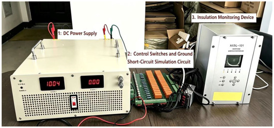
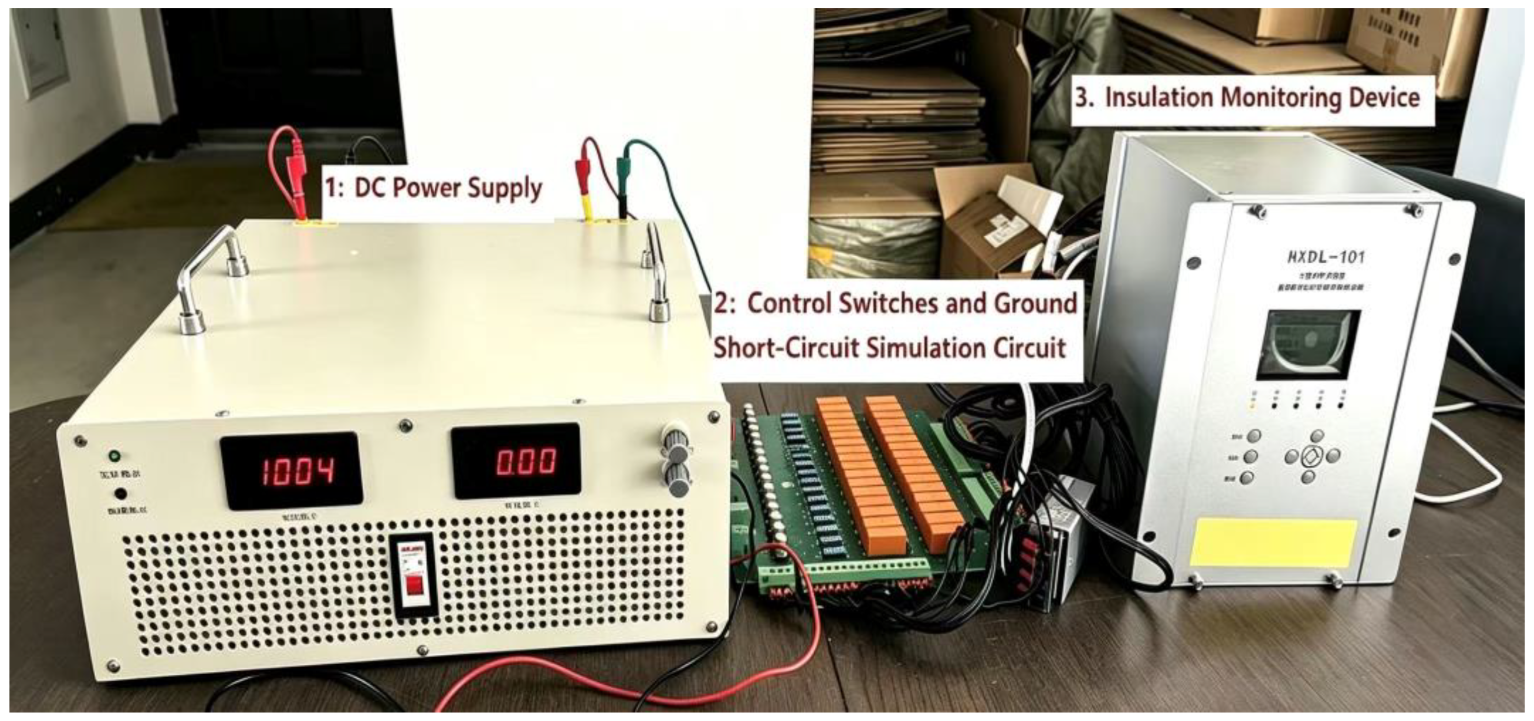
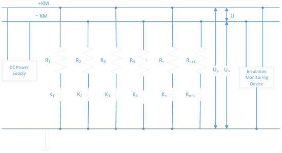
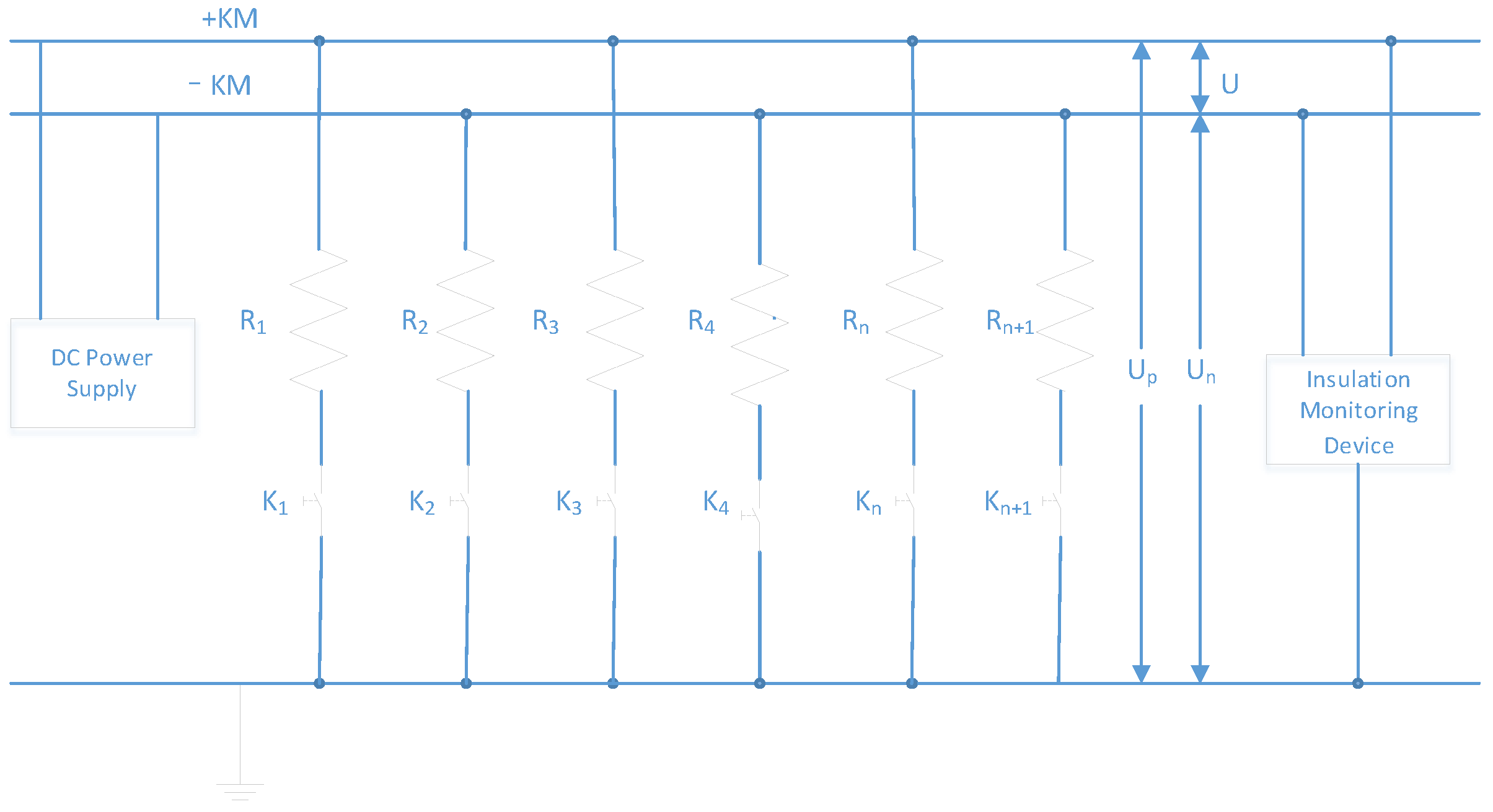
As shown in Figure 4 and Table 1, Device 1 is a high-power constant-voltage constant-current switching power supply used to simulate the DC voltage output of PV strings, with its output voltage continuously adjustable from 0 to 1500 V and a maximum output power of 2000 W. Device 2 is a self-developed simulation test circuit used to simulate the string disconnecting switches and their corresponding loop short circuits in PV stations. In this circuit, every 4 small relays form a switching unit, capable of simulating switch closing, tripping operations, and auxiliary contact outputs, with a total of 8 branches simulated. As shown in Figure 5, short-circuit faults are simulated by connecting resistors in parallel from the positive or negative pole to ground, where K1~Kn are switching buttons; pressing the corresponding button in Device 2 connects the positive or negative pole to ground through a resistor. When multiple buttons are pressed simultaneously, composite faults such as multiple branches grounding simultaneously or both positive and negative poles grounding can be simulated. Device 3 is the self-developed DC grounding line selection and intelligent control device, which collects DC bus voltage and calculates insulation resistance accordingly, and can perform switching control on up to 16 PV loops.
Figure 4.
DC system insulation test experimental platform.
Table 1.
Description of experimental platform equipment in Figure 4.
Figure 5.
DC insulation test platform structure diagram.
System experimental parameters were set as follows:
- Busbar rated voltage:
- Balanced bridge resistors:
- Unbalanced bridge resistors:
Considering that the voltage measurement loop also connects sampling resistors in parallel between the positive and negative poles and ground, the balanced bridge resistors here are actually the sampling resistors, and their values are consistent with those in Section 3.1.
5.1. Experimental Results of the Balanced Bridge Method
Table 2 and Table 3 present the measurement results of the balanced bridge method under positive and negative pole short circuits to ground, respectively, with different external standard resistors. “Unoptimized” refers to the device directly collecting and to calculate the insulation resistance, while “optimized” refers to the proposed reconstruction algorithm automatically selecting the highest-precision data to calculate the insulation resistance.
Table 2.
Measurement of Positive Pole Short Circuit to Ground for Balanced Bridge.
Table 3.
Measurement of Negative Pole Short Circuit to Ground for Balanced Bridge.
5.2. Unbalanced Bridge Method Experimental Results
Table 4 and Table 5 present the measurement results of the unbalanced bridge method under positive and negative pole short circuits to ground, respectively, with different external standard resistors.
Table 4.
Measurement of Positive Pole Short Circuit to Ground for Unbalanced Bridge.
Table 5.
Measurement of Negative Pole Short Circuit to Ground for Unbalanced Bridge.
5.3. Results Analysis and Discussion
- (1)
- Comparable performance under high-resistance conditions. When the insulation resistance is above 100 kΩ, the measurement accuracy before and after optimization shows little difference, with errors all better than 5%. At this time, the positive and negative pole-to-ground voltages are both within the optimal linear range of the measurement system, and voltage measurement accuracy can be guaranteed within 1%; the ill-posedness problem is not significant.
- (2)
- Traditional methods fail under low-resistance conditions. When the insulation resistance drops to 86 kΩ, the error of the unoptimized algorithm increases sharply—minimum 17.4% (balanced bridge positive pole), maximum 30.2% (unbalanced bridge positive pole). When the insulation resistance further drops to 22 kΩ, the error of traditional methods exceeds 300%, and the measurement results are completely distorted. This verifies the theoretical prediction of the ill-posedness analysis in Section 1.
- (3)
- The proposed method maintains high accuracy under all conditions. After optimization, the algorithm keeps errors within 5% for all fault types and all resistance values. Especially under the extreme condition of 22 kΩ, the error is reduced from over 300% to within 5%, an improvement of more than one order of magnitude.
From the above test results, it can be seen that under severe single-pole short circuit to ground, the measurement accuracy after optimization using the proposed method significantly exceeds the requirements specified in DL/T 1392-2014 “Technical Specifications for Insulation Monitoring Devices of DC Power Supply Systems.”
5.4. Comparative Analysis of Voltage Measurement Data
To further reveal the source of errors, Table 6 presents the voltage measurement data under various conditions for the balanced bridge positive pole short circuit.
Table 6.
Voltage Measurement for Balanced Bridge Positive Terminal Short-to-Ground.
From Table 6, the following observations can be made:
- (1)
- The unoptimized measurement is severely distorted. When the short-circuit resistance drops to 86 kΩ, the unoptimized method measures as 81.7 V, while the true value should be around 71.5 V, an error of 14%. When the short-circuit resistance drops to 22 kΩ, the unoptimized method measures as 79.4 V—this is actually the system’s zero-drift voltage (the positive-to-ground zero drift of this experimental platform without DC voltage is 76.6 V), far from the true value of 22 V. This verifies the prediction of the heteroscedastic model in Section 3.1: when the signal amplitude drops below the zero-drift level, the measured value is completely dominated by noise.
- (2)
- After optimization, is obtained with high precision through constraint inversion. The optimized is not a direct measured value, but is calculated from . Since the channel has enhanced signal during positive grounding ( approaches ), its measurement accuracy is very high, so the inferred also has high accuracy. When the short-circuit resistance is 22 kΩ, the optimized is 22 V, highly consistent with the true value.
It should be noted that the proposed method targets the most intractable scenario of the traditional bridge method—severe single-pole grounding. For the case where insulation resistances of both positive and negative poles decrease symmetrically, and still maintain , both channels operate in high SNR regions, and the weighted average in Equations (11) and (12) naturally degenerates to ; the redundancy-constrained fusion estimation of this paper remains applicable.
5.5. Verification of Line Selection Function
Based on the verification of insulation measurement accuracy, the effectiveness of the proposed line selection strategy was further verified. The experiment set up 8 parallel branches, and a 22 kΩ grounding resistor was inserted into one branch to simulate a single-pole grounding fault. The system performed sequential branch switching tests according to the procedure described in Section 4. During the switching process, considering the capacitance charging and discharging in the actual environment, the line startup switching interval was set to 3 s (adjustable)—that is, after each switch opening or closing, the system waited 3 s before measuring the bus insulation state. The results showed that the system could complete the detection and judgment of all 8 branches within 30 s; the faulty branch was accurately identified and automatically disconnected, and the non-faulty branches were automatically restored after the detection was completed, without any manual intervention throughout the process, verifying the accuracy and full automation capability of the line selection algorithm.
6. Conclusions
Compared with existing line selection schemes based on leakage current sensors or signal injection methods, the proposed method achieves substantial improvements in three aspects. At the measurement accuracy level, existing research on improving the bridge method mostly focuses on topology optimization or parameter tuning, failing to reveal the mathematical essence of the ill-conditioned measurement equations under severe single-pole grounding, resulting in measurement errors as high as over 300% under extreme conditions. This paper fundamentally overcomes this accuracy bottleneck by introducing voltage redundancy constraints to transform the ill-posed inverse problem into a constrained optimal estimation. At the line selection approach level, existing schemes rely on a large number of sensors or external injection signals, resulting in high system complexity and difficulty in achieving online line selection. This paper leverages the operational characteristic that PV systems allow short-term branch interruption and completes fault localization solely based on bus insulation resistance measurements, achieving intelligent line selection without additional sensors. At the system architecture level, existing research mostly separates insulation monitoring and fault line selection as independent functions, lacking a complete closed loop from sensing to execution. This paper integrates high-precision measurement with sequential branch switching decisions, achieving automatic fault detection, automatic isolation, and automatic restoration of non-faulty branches. The combined effect of the above improvements makes the proposed method superior to existing schemes in terms of engineering applicability, degree of automation, and measurement reliability. Based on the above analysis, the main conclusions of this paper are as follows:
- (1)
- The mathematical essence of the measurement accuracy degradation of the traditional bridge method is revealed. The measurement accuracy of both the balanced bridge and unbalanced bridge methods critically depends on voltage measurement accuracy. When the voltage of one pole to ground is greatly attenuated due to severe insulation degradation, the condition number of the measurement equation tends to infinity, constituting a typical ill-posed inverse problem. At this point, the measured values of the weak signal channel are almost completely dominated by noise, and the failure of traditional methods under such conditions is inevitable, rather than a simple issue of insufficient hardware precision.
- (2)
- A measurement reconstruction method based on voltage redundancy constraints is proposed. Utilizing the inherent physical constraint that the sum of the positive and negative pole-to-ground voltages always equals the bus voltage, a weighted least squares optimal estimation model with equality constraints is established, and the analytical solution in the sense of constrained least squares is derived. Through a soft switching mechanism, this method automatically identifies and abandons unreliable measurement channels, instead adopting the constraint-inferred value from the high-precision channel to reconstruct weak signals, fundamentally avoiding the error amplification problem caused by direct measurement of small signals.
- (3)
- A collaborative monitoring strategy combining the balanced bridge and unbalanced bridge is designed. The balanced bridge serves as a continuous “sentry” for real-time monitoring of bus insulation status; the unbalanced bridge serves as a “precision tool” that is only engaged for precision measurement upon detection of insulation anomalies. The two complement each other, ensuring real-time monitoring while avoiding system disturbances and equipment life reduction caused by frequent relay switching in the unbalanced bridge mode.
- (4)
- A sensorless intelligent line selection method is proposed. Leveraging the operational characteristic that PV systems allow short-term branch interruption, the line selection problem is modeled as a binary decision problem based on switching vectors and the insulation resistance function. A sequential branch switching algorithm for both single-fault and multiple-fault scenarios is designed, and the convergence of the algorithm within two rounds of switching is proven. This method does not require leakage current sensors, fundamentally avoiding the difficulties of sensor installation and insufficient weak signal detection accuracy.
- (5)
- Experimental results show that under severe fault conditions with single-pole insulation resistance as low as 22 kΩ, the measurement error of traditional methods exceeds 300%, while the proposed reconstruction algorithm limits the error to within 5%, an improvement of more than one order of magnitude. In line selection experiments with 8 branches, the system can accurately identify and automatically disconnect the faulty branch within 30 s, with non-faulty branches automatically restored, without any manual intervention throughout the process.
The proposed method does not require major changes to the existing hardware structure; only the replacement of existing manual switches with automatic switches, combined with the high-precision insulation measurement algorithm and intelligent line selection strategy, can achieve automatic monitoring, automatic line selection, and automatic isolation of DC grounding faults, offering good engineering practical value.
Author Contributions
Conceptualization, B.L. and X.L.; methodology, B.L.; software, B.L.; validation, B.L.; formal analysis, B.L.; investigation, B.L.; data curation, B.L.; writing—original draft preparation, B.L.; writing—review and editing, X.L.; visualization, B.L.; supervision, X.L.; project administration, X.L. All authors have read and agreed to the published version of the manuscript.
Funding
This research was funded by the National Natural Science Foundation of China (NSFC), Grant No. U22B20106.
Data Availability Statement
Data are contained within the article.
Conflicts of Interest
The authors declare no conflicts of interest.
References
- Yang, Q.; Huang, X.; Chai, W. Research on Insulation Detection Method for Photovoltaic DC System. Power Syst. Clean Energy 2017, 33, 129–133. [Google Scholar] [CrossRef]
- Alam, M.K.; Khan, F.; Johnson, J.; Flicker, J. A Comprehensive Review of Catastrophic Faults in PV Arrays: Types, Detection, and Mitigation Techniques. IEEE J. Photovolt. 2015, 5, 982–997. [Google Scholar] [CrossRef] [Scilit]
- Flicker, J.; Johnson, J. Photovoltaic Ground Fault Detection Recommendations for Array Safety and Operation. Sol. Energy 2016, 140, 34–50. [Google Scholar] [CrossRef] [Scilit]
- Guerrero, J.M.; Serrano-Jimenez, D.; Mahtani, K.; Platero, C.A. A Ground Fault Location Method for DC Systems Through Multiple Grounding Connections. IEEE Trans. Ind. Appl. 2022, 58, 7022–7033. [Google Scholar] [CrossRef] [Scilit]
- Ribeiro, E.; Cardoso, A.J.M.; Boccaletti, C. Fault-Tolerant Strategy for a Photovoltaic DC-DC Converter. IEEE Trans. Power Electron. 2013, 28, 3008–3018. [Google Scholar] [CrossRef] [Scilit]
- Anaya-Ruiz, G.A.; Ruiz, D.; Ugalde Caballero, L.E.; Moreno-Goytia, E.L. Design and Prototyping of Transformerless DC-DC Converter with High Voltage Ratio for MVDC Applications. IEEE Lat. Am. Trans. 2023, 21, 62–70. [Google Scholar] [CrossRef] [Scilit]
- Poulek, V.; Aleš, Z.; Finsterle, T.; Libra, M.; Beránek, V.; Severová, L.; Belza, R.; Mrázek, J.; Kozelka, M.; Svoboda, R. Reliability Characteristics of First-Tier Photovoltaic Panels for Agrivoltaic Systems—Practical Consequences. Int. Agrophys. 2024, 38, 383–391. [Google Scholar] [CrossRef] [Scilit] [PubMed]
- DL/T 1392-2014; Technical Specifications for Insulation Monitoring Devices of DC Power Supply Systems. China Electric Power Press: Beijing, China, 2014.
- GB/T 34131-2023; Battery Management System for Electric Energy Storage. Standards Press of China: Beijing, China, 2023.
- Wang, J.; Zhang, M.; Bao, L.; Cai, L. Design of Insulation Monitoring Device for Photovoltaic DC System. Autom. Appl. 2016, 137–139. [Google Scholar] [CrossRef]
- He, Y.R.; Xu, Z.G.; Zhao, J.; Zheng, L. Based on the Combination of Unbalanced and Balanced Bridge DC Insulation Monitoring Technology. Power Sci. Eng. 2007, 23, 30–32. [Google Scholar] [CrossRef]
- Hu, L.; Ji, P.; Qin, W.; Yang, Q.; Chen, T. Design of an Optimized Online Insulation Monitoring Device for DC System in Photovoltaic Power Station. Power Syst. Clean Energy 2016, 32, 130–134. [Google Scholar] [CrossRef]
- Wu, Z.; Wang, H.; Sun, L.; Geng, L. Improved DC Insulation Detection Method for Photovoltaic Array. Sol. Energy 2016, 56–61. [Google Scholar] [CrossRef]
- Du, J. Research on Key Technologies of Insulation Monitoring for DC System. Ph.D. Thesis, Beijing Jiaotong University, Beijing, China, 2020. [Google Scholar] [CrossRef]
- Cheng, L.; Dai, Y.; Xiong, S. Online Insulation Supervising for DC System and Its Realization. J. Electron. Meas. Instrum. 2015, 29, 860–865. [Google Scholar] [CrossRef]
- Hansen, P.C.; O’Leary, D.P. The Use of the L-Curve in the Regularization of Discrete Ill-Posed Problems. SIAM J. Sci. Comput. 1993, 14, 1487–1503. [Google Scholar] [CrossRef] [Scilit]
- Calvetti, D.; Morigi, S.; Reichel, L.; Sgallari, F. Tikhonov Regularization and the L-Curve for Large Discrete Ill-Posed Problems. J. Comput. Appl. Math. 2000, 123, 423–446. [Google Scholar] [CrossRef] [Scilit]
- Groetsch, C.W. Regularization of Ill-Posed Problems with Unbounded Operators. J. Math. Anal. Appl. 2002, 271, 542–545. [Google Scholar] [CrossRef] [Scilit][Green Version]
- Lei, X.; Xu, N.; Pan, X.; Dai, C.; Xu, Z.; Dong, Z. Research on Line Selection Verification Mechanism of DC Grounding Fault Inspection in Substation. Power Syst. Prot. Control 2015, 43, 112–118. [Google Scholar] [CrossRef]
- Kulathinal, S.B.; Kuulasmaa, K.; Gasbarra, D. Estimation of an Errors-in-Variables Regression Model When the Variances of the Measurement Errors Vary between the Observations. Stat. Med. 2002, 21, 1089–1101. [Google Scholar] [CrossRef] [Scilit] [PubMed]
- Van Loan, C.F. On the Method of Weighting for Equality-Constrained Least-Squares Problems. SIAM J. Numer. Anal. 1985, 22, 851–864. [Google Scholar] [CrossRef] [Scilit]
- Tao, X.; Lu, M. Analysis and Calculation of Insulation Resistance in DC System. East China Electr. Power 2000, 28, 55. [Google Scholar] [CrossRef]
- Du, J.; Zheng, T.Q.; Yan, Y.; Zhao, H.; Zeng, Y.; Li, H. Insulation Monitoring Method for DC Systems with Ground Capacitance in Electric Vehicles. Appl. Sci. 2019, 9, 2607. [Google Scholar] [CrossRef] [Scilit]
- Mehmood, A.; Sher, H.A.; Murtaza, A.F.; Al-Haddad, K. Fault Detection, Classification and Localization Algorithm for Photovoltaic Array. IEEE Trans. Energy Convers. 2021, 36, 2945–2955. [Google Scholar] [CrossRef] [Scilit]
- Li, J. Integrated Device for DC Insulation Monitoring and Grounding Point Location. Jiangsu Electr. Appar. 2006, 2, 48. [Google Scholar]
- Feng, C.; Ye, P.; Gao, Z.; Jiang, H.; Zang, X.; Zhang, X. A Novel Distributing–Collecting On-Line Insulation Monitoring System and Line Selection Technology for the DC Supply System. Front. Energy Res. 2023, 11, 1291552. [Google Scholar] [CrossRef] [Scilit]

Disclaimer/Publisher’s Note: The statements, opinions and data contained in all publications are solely those of the individual author(s) and contributor(s) and not of MDPI and/or the editor(s). MDPI and/or the editor(s) disclaim responsibility for any injury to people or property resulting from any ideas, methods, instructions or products referred to in the content. |
© 2026 by the authors. Licensee MDPI, Basel, Switzerland. This article is an open access article distributed under the terms and conditions of the Creative Commons Attribution (CC BY) license.