1. Introduction
The incessant increase in energy needs around the globe, due to fast-paced industrialization, high population numbers, and improved standards of living, has created an alarm about energy consumption and sustainability. This has made energy management and conservation in thermal losses significant engineering and environmental goals [
1,
2,
3]. Heat exchangers are used in many industrial processes that involve production of power, chemicals, cryogenics, aviation, petrochemical manufacturing, and HVAC among others where efficient use of thermal energy is necessary [
4]. Heat exchangers are one of the critical elements in thermal systems because of the ability to allow the transfer of thermal energy from one fluid to another without any mixing of them [
5,
6]. Due to high energy requirements of these devices in industry, research into new highly efficient heat exchangers is of considerable interests [
7,
8,
9].
The various heat transfer enhancement methods can be broadly categorized into active and passive methods. The active methods require some sort of energy input externally for improving the thermal behavior of the heat exchanger [
10]. On the other hand, passive methods enhance the heat transfer without the need for any input of energy from outside. The passive methods are basically based on the alteration of flow geometries or use of flow disruptors in order to create turbulent flow [
11]. Common passive enhancement techniques include twisted tapes, helical coiled wires, corrugated tubes, nanofluids, and coiled or curved tubes. Because of their simplicity, lower cost, and ease of implementation, passive methods are widely used in industrial heat exchangers.
Among passive heat transfer enhancement techniques, twisted tape inserts have attracted considerable attention due to their ability to generate swirl flow and disturb the thermal boundary layer. Luo et al. proposed a novel special-shape twisted tape (SSTT) turbulator combined with a helical coiled wire (HCW) insert to improve the thermo-hydraulic performance of heat exchanger tubes [
12]. The results of their analysis revealed that SSTT alone improved the heat transfer efficiency by 124% while a combined use of SSTT and HCW inserts improved it up to 142%. One more widely explored heat transfer enhancement technology is dimpled surface technology. Nazari et al. numerically explored the impact of dimple pattern, dimple count, and dimple depth on the thermo-hydraulic performance of rectangular channel subjected to a turbulent flow regime [
13]. The results have shown that the formation of vortices due to dimples caused significant improvement in convective heat transfer by continuously mixing hot fluid in the vicinity of wall with cold fluid in the core region. It was established that the optimal combination of staggered dimple arrangement with a depth ratio of
led to the maximum increase in the Nusselt number, which equaled to 20%, and thermal performance factor, which was nearly 11% higher at Reynolds number of 50,000. In addition to the studies on straight twisted ducts, the research community has also focused on curved and spiral coiled tubes. Khoshvaght-Aliabadi et al. studied a new type of spirally coiled twisted-duct heat exchanger and found out that the combination of twisting effect and curving improved thermal efficiency [
14]. The findings indicated that there was a 28.4% increase in the heat transfer. More recently, Farhadi et al. combined numerical simulation with experimental testing to develop updated Nusselt number and friction coefficient correlations for spiral coiled tubes, reporting that a coiled flow reverser configuration increased the overall heat transfer coefficient by 39.5–49.9% relative to a straight helical tube [
15]. In a related study, Zhang et al. showed that for helically coiled tubes with large curvature ratios the Dean number alone is insufficient to characterize flow and heat transfer behavior, indicating that additional curvature related parameters must be accounted for when designing curved tube heat exchangers [
16]. There have been a lot of promising results regarding heat transfer improvement using nanofluids. Albadr et al. experimentally studied Al
2O
3/water nanofluids with particle volume concentrations varying between 0.3% and 2%, flowing under turbulent conditions through shell and tube heat exchanger [
17]. It was found that an increase in nanoparticle concentrations can be used to improve heat transfer. In particular, when the nanoparticles were 2%, the Nusselt number increased from 367.76 in distilled water to 587 in nanofluid, which is an improvement of 62.6%. Unlike passive methods, active methods require constant input of energy externally to influence local flow dynamics. Electrodynamic (EHD) techniques can be classified as active methods that have proven to be quite effective in improving convective heat transfer through the production of secondary flows and vortices caused by an electric field. Mirzaei and Saffar-Avval experimentally and numerically analyzed EHD conduction pumping in an annular heat exchanger in which transformer oil served as the working fluid [
18]. The influence of mechanical rotation on the thermal performance of heat exchangers is another active method that has been demonstrated to enhance heat transfer. Dabestani and Kahani reported that rotating the spiral tube significantly intensified fluid mixing, reduced thermal boundary layer thickness, and enhanced convective heat transfer within the system; they found that the performance factor increased from 1.76 at 1 rpm to 2.30 at 4 rpm [
19]. The application of an external magnetic field significantly altered the flow structure and enhanced the thermal performance of the compact heat exchanger. Bezaatpour and Rostamzadeh reported that the magnetic field generated strong Kelvin body forces around the heated tubes, which induced vortex formation and intensified fluid mixing inside the channels [
20]. They showed that the presence of magnetic field remarkably enhanced the heat transfer characteristics. The mean heat transfer rate rose up to about 52.4% higher due to the presence of the external magnetic field, while just the use of 2 vol.% of magnetite particles without a magnetic field only achieved 8.7% improvement. In order to surpass the thermodynamic performance limitations of single intensification techniques, scientists have been working on compound systems that involve both active and passive enhancement techniques. Akcay studied the compound enhancement technique using pulsating flow with corrugated channels and V-type winglets [
21]. The study showed that the combined method achieved maximum thermal enhancement ratios up to 7.52 for the channels with perforated winglets.
The literature has proven that both types of heat transfer enhancement techniques play a vital role in improving thermal efficiency through fluid mixing, breaking up of the thermal boundary layer, and secondary flow formation. Rotating Horizontal Spiral with Flow Reversers (HSFRs) as a combination of both passive and active methods, has shown a high level of promise in spiral heat exchanger systems, where the periodic regeneration of secondary flow and improved heat transfer is achieved in comparison to standard horizontal spiral tubes (HST) of equal heat transfer area [
22]. However, although flow reversers demonstrate very good performance, systematic optimization of geometric parameters determining their efficiency has not yet been carried out. In particular, there has been no research devoted to the effect of turn diameter of the reverser, distribution frequency of reversers along the spiral channel, and reverser tube diameter on the performance of such devices. This gap is consequential: unlike the other passive enhancement strategies reviewed above, for which the governing geometric parameters have been systematically mapped, for example dimple pattern, count and depth ratio in rectangular channels [
13], or tape geometry in twisted tape/helical coiled wire inserts [
12], the reverser geometry in HSFR systems has, in every prior study, been fixed to a single, arbitrarily chosen configuration. Without a systematic parametric characterization, it cannot be established whether the previously reported thermal enhancement of HSFR represents a near-optimal design or one that leaves substantial performance, or unnecessary pressure drop penalty, on the table. Closing this gap is essential both for deriving reliable design guidelines for HSFR heat exchangers and for enabling a fair, quantitative comparison against other established passive and active enhancement techniques. The current paper continues research carried out on the topic of flow reversers in order to perform a geometric optimization analysis. The main aim of the study will be the identification of the optimal reverser geometry which allows maximum heat transfer enhancement with minimum pressure-drop.
This paper is organized as follows.
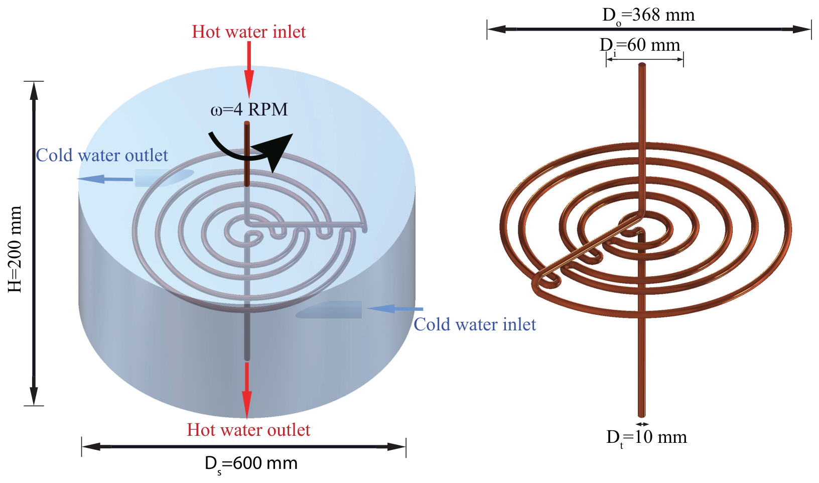
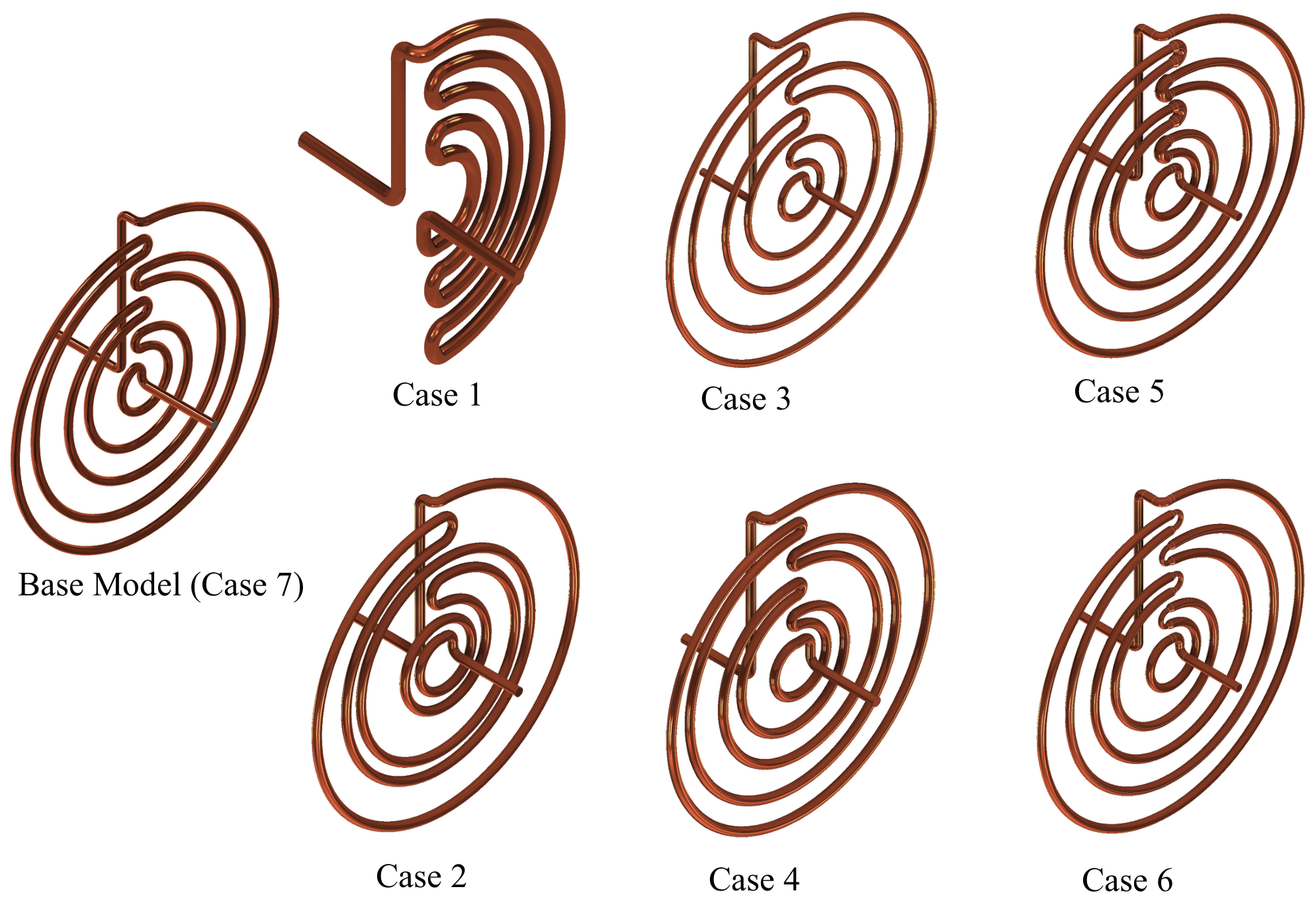
Section 2 presents the computational methodology, including the physical configuration of the baseline rotating horizontal spiral heat exchanger with flow reversers and the geometric modifications considered in the present study. The investigated cases are described in detail.
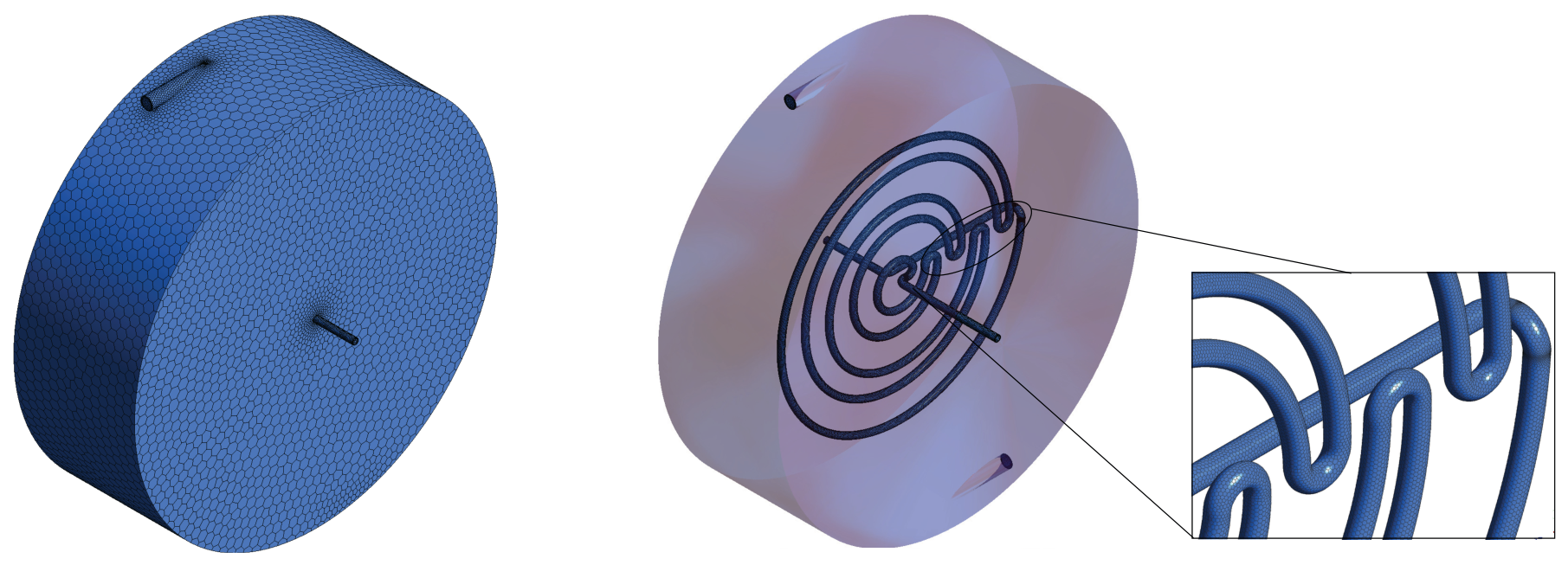
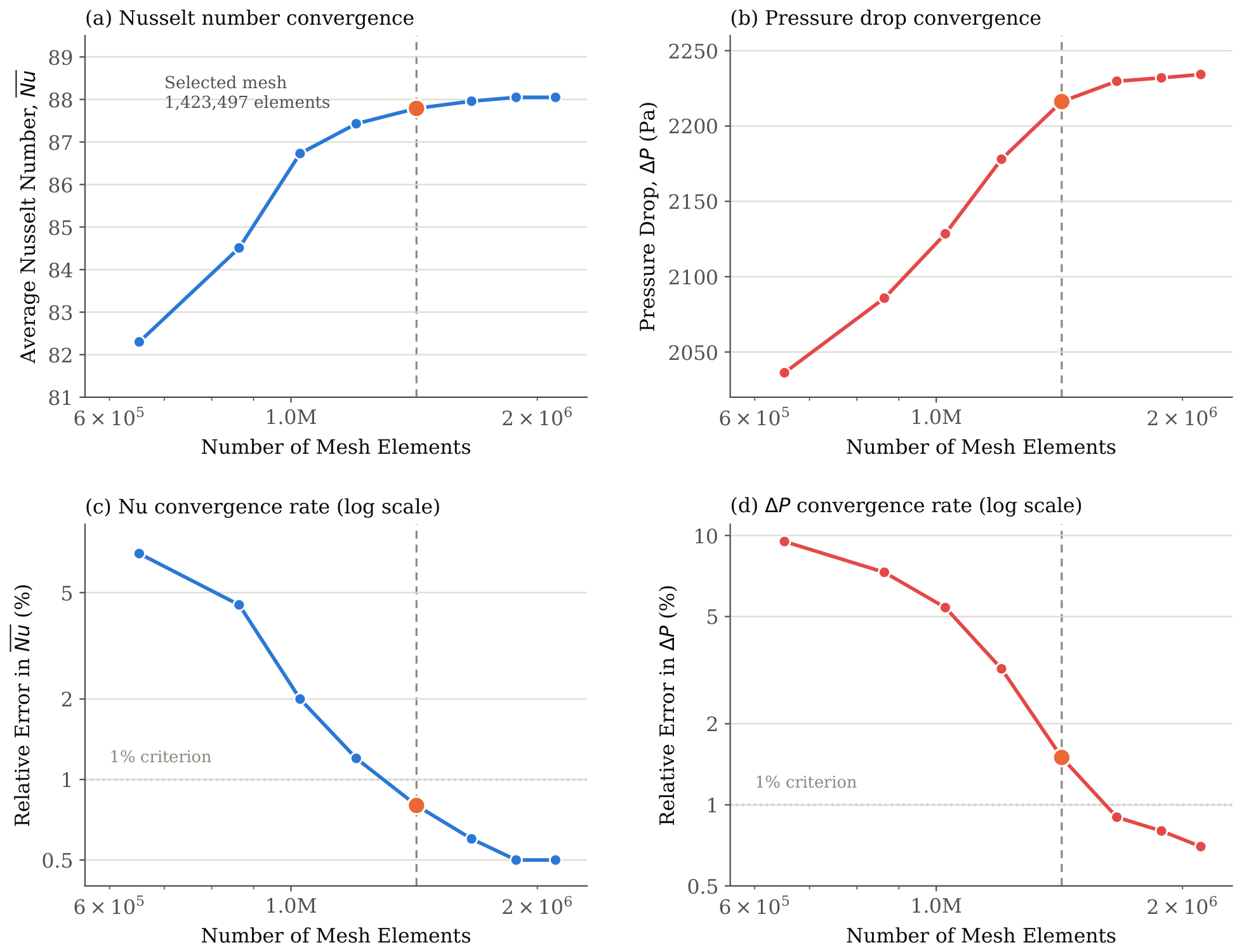
Section 3 outlines the numerical methodology, including the grid analysis and model validation process employed to ensure the accuracy and reliability of the simulations.
Section 4 presents and discusses the results, focusing on the effects of the investigated geometric parameters on flow behavior, heat transfer characteristics, pressure drop, and overall thermo-hydraulic performance. Finally, the main findings and conclusions of the study are summarized in
Section 5.
4. Results and Discussion
A parametric study was conducted to evaluate the impact of reverser geometry on the flow and heat transfer behavior of the heat exchanger. Three geometric parameters were examined, namely the reverser turn diameter, reverser distribution frequency along the spiral channel, and reverser tube diameter (blockage ratio). The effects of these parameters on fluid flow and heat transfer mechanisms were evaluated by analyzing the velocity distribution, temperature field, and Nusselt number.
4.1. Validation
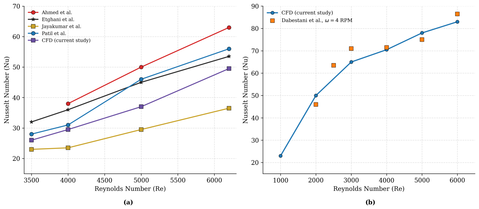
To test the reliability and predictability of the current numerical approach, a validation process was carried out in two steps. At first, the validation was done for the static model of a horizontal spiral tube without any reversers to form the simplest case before adding the effect of tube rotation. As shown in
Figure 5a, the computed Nusselt numbers were compared against the correlations of Ahmed et al. [
33], Etghani & Baboli [
34], Jayakumar et al. [
35], and Pati et al. [
36] over the Reynolds number range of 3500–6200. The present CFD results reproduce the expected monotonic increase in Nusselt number with Reynolds number and fall within the scatter band defined by the reference correlations across the entire range considered, lying closest to the predictions of Pati et al. [
36] and consistently above the lower bound set by Jayakumar et al. [
35]. This agreement confirms that the baseline numerical setup, mesh resolution, and turbulence modeling choices adequately capture convective heat transfer in a stationary spiral channel before any rotation or reverser effects are introduced.
To check the ability of the numerical model to represent the transport phenomena caused by rotation of the tube, an additional validation test has been performed.
Figure 5b compares the computed Nusselt numbers with the numerical results of Dabestani et al. [
19] at
RPM over the Reynolds number range of 1000–6000. The present CFD predictions track the reference data closely across the full range, with the largest deviations occurring at the lowest and intermediate Reynolds numbers (
–3000) and agreement improving progressively at higher Reynolds numbers. This consistent agreement demonstrates the capability of the rotating reference frame approach to capture the centrifugal and Coriolis effects associated with rotation, as well as the resulting secondary flow field development, across the full range of operating conditions considered. The current CFD predictions match very well the reference values all through the range considered. This agreement proves the ability of the rotating reference frame method to describe the centrifugal and Coriolis forces generated by the rotation and the formation of secondary flows under the action of these forces for all ranges of the parameters considered. Overall, the good agreement attained in both validation cases confirms the correctness of the proposed CFD technique for prediction of heat transfer in stationary and rotating horizontal spiral configurations, which allows using it as a tool for parametric analysis of the reverser geometry described in the following sections.
4.2. Effect of Reverser Geometry on the Local Flow Field
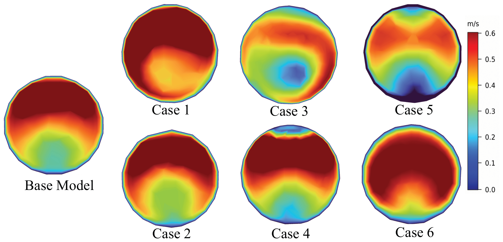
Figure 6 presents the local velocity contours at the final reverser for the base configuration and the six modified geometries. All configurations exhibit an asymmetric velocity distribution. This behavior is characteristic of curved passages, where centrifugal forces generate counter rotating Dean vortices. The intensity of these secondary flows is commonly characterized by the Dean number,
where
is the Reynolds number,
is the hydraulic diameter, and
is the local radius of curvature. Since all simulations were performed under identical operating conditions and at the same Reynolds number, the observed differences in the velocity field can be attributed solely to the geometric modifications of the flow reversers. These geometric variations alter the local radius of curvature and the available flow passage, thereby changing the intensity of the curvature induced secondary flow and the resulting velocity distribution.
The influence of reverser distribution frequency can be evaluated by comparing Cases 1 and 2 with the base model. Case 1 employs one reverser every half turn, whereas Case 2 incorporates one reverser every two spiral turns. The shorter spacing between consecutive reversers in Case 1 prevents complete redevelopment of the hydrodynamic boundary layer before the flow encounters the next disturbance. Consequently, the Dean vortices generated by one reverser remain active when entering the following reverser, resulting in stronger secondary circulation and a more pronounced velocity asymmetry. In contrast, the larger spacing in Case 2 allows partial recovery of the velocity profile between successive reversers, reducing the persistence of secondary vortices. As a result, the velocity field in Case 2 closely resembles that of the base model, indicating that increasing the spacing between reversers weakens the cumulative enhancement mechanism.
Cases 3 and 4 isolate the influence of the reverser turn diameter while maintaining the same tube diameter and reverser frequency. Increasing the turn diameter from 20 mm to 30 mm (Case 3) represents a 50% increase in the curvature diameter, resulting in a smoother flow path and weaker centrifugal effects. In contrast, decreasing the turn diameter from 20 mm to 15 mm (Case 4), corresponding to a 25% reduction, produces a tighter bend with stronger local curvature. The resulting increase in centrifugal effects. This stronger velocity skewness indicates enhanced secondary motion and greater disruption of the hydrodynamic boundary layer.
A different flow mechanism governs Cases 5 and 6, where the reverser tube diameter is modified while the turn diameter remains constant. Increasing the reverser tube diameter from 10 mm to 15 mm (Case 5) enlarges the tube cross sectional area from 78.5 mm2 to 176.7 mm2, corresponding to a 125% increase in flow area. Under a constant mass flow rate, the larger flow area reduces the local mean velocity according to the continuity equation, resulting in a broader low velocity region and a weaker high speed core. Conversely, decreasing the reverser tube diameter from 10 mm to 6 mm (Case 6) reduces the cross sectional area from 78.5 mm2 to 28.3 mm2, representing a 64% reduction. As the same mass flow rate is forced through a substantially smaller flow passage, the local velocity increases significantly, producing a more concentrated high velocity core and higher wall shear stress. The resulting increase in inertial effects enhances secondary flow intensity and continuously disrupts the thermal boundary layer.
4.3. Effect of Reverser Geometry on Shell-Side Temperature Distribution
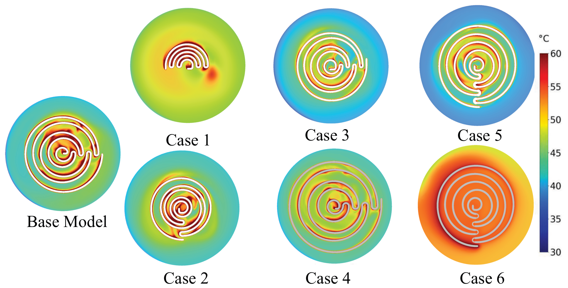
Figure 7 shows the temperature distribution on the shell side in the base model and six variants of modification. The temperature field provides direct information on the efficiency of the design in terms of increasing the heat transfer and mixing of the shell side fluids. Typically, efficient design of the reverser should ensure the higher uniformity of the temperature field due to the constant breakdown of the thermal boundary layer and heat transfer through the hot and cold regions.
As compared to the base model, Case 1, where a reverser is located every half-turn, shows the most uniform temperature distribution in the shell domain among the base model and Case 2. The heated region near the spiral channel occupies a greater area, while the temperature gradient near the channel becomes less pronounced. This situation suggests that the presence of frequently appearing reversers constantly disrupts the thermal boundary layer, thus forcing the shell side fluid to experience continuous change of distribution and mixing. As a result, heat is transferred more effectively from the hot tube wall to the shell fluid, and the thermal diffusion becomes more intensive. On the contrary, Case 2 is practically similar to the base model with the placement of only one reverser in each turn. In both designs, the temperature gradients around the spiral channel and heat transfer into the shell side fluid are quite similar. This fact can suggest that within this range, the change of the frequency of the reverser placement from one per turn to one per two turns has no significant influence on the heat transfer process.
Cases 3 and 4 provide insight into the effect of reverser turn diameter. The increase in reverser turn diameter (Case 3) causes weakening of thermal mixing due to smoothing of the flow path and decrease in the flow curvature with the resulting decrease in the secondary flow impingement and preserving of the thermal boundary layer integrity; thus, heat is transferred concentrically with the high temperature regions close to the tube while the penetration of heat to the shell fluid is limited. The opposite effect is observed in Case 4, when the reduction in the reverser turn diameter causes better mixing with the formation of the more uniform temperature field featuring higher thermal diffusion. Though some variations in the temperature field are observed in the region of the spiral channel, they do not significantly differ from the temperature distribution in the baseline case.
Cases 5 and 6 provide insight into the effect of reverser tube diameter. As opposed to the above mentioned geometric modification, the variation of the blockage ratio leads to essential alterations in the shell-side temperature field. In the Case 5 with the increase in the reverser tube diameter and the flow area, the secondary flow is decreased with the resulting restriction of the thermal field penetration into the outer shell side. It is thus clear that the increased reverser tube diameter confines the thermal field close to the heat transfer surface instead of promoting the large-scale thermal mixing. Conversely, in Case 6, when the reverser tube diameter is reduced, the flow area is decreased, and the flow acceleration is intensified. The resulting shell-side temperature becomes more uniformly distributed with smooth temperature gradients extended farther from the spiral channel. Thus, it is obvious that the blockage ratio mainly determines the heat transfer capability of the heat exchanger.
In general, the temperature distribution allows concluding that the main mechanisms of the thermal performance of the rotating spiral heat exchanger are the increase in the secondary flow due to the reverser and the thermal boundary layer disruption caused by it. Among all configurations considered, the best shell-side thermal mixing with the highest heat diffusion and the most uniform temperature distribution corresponds to the half-turn reverser (Case 1) and the smaller reverser tube diameter (Case 6).
4.4. Effect of Reverser Geometry on Nu
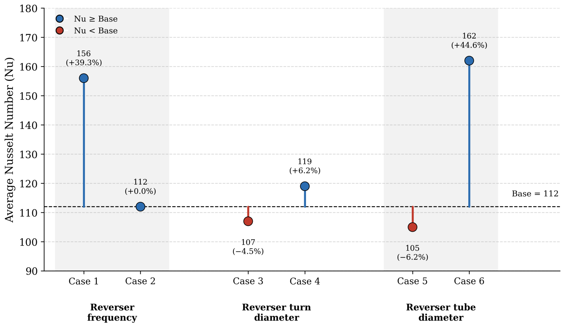
Figure 8 shows the comparison of average Nusselt number for all configurations under consideration classified according to the geometric parameter which is determined by each pair of cases: reverser distribution frequency, reverser turn diameter, and reverser tube diameter. Average Nusselt number of the base configuration equals 112 and this figure will be considered as the reference point for all following percentage changes.
The effect of reverser distribution frequency can be estimated by comparison of Cases 1 and 2 with the base model. Implementation of the reverser every half-turn (Case 1) causes average Nusselt number to increase up to approximately 156 or 39.3% compared to the base model because of continuous regeneration of secondary flow which hinders redevelopment of thermal boundary layer and significantly improves heat transfer rate. Decreasing frequency to one reverser per two turns (Case 2) causes average Nusselt number to remain at approximately 112, that makes no difference from the base configuration. It means that induced by the reverser secondary flow persists during relatively large distance along the spiral channel and widely spaced reversers provide little addition to thermal performance of the geometry.
Effect of reverser turn diameter is investigated using Cases 3 and 4. Reduction in turn diameter (Case 4) leads to average Nusselt number rise up to approximately 119 and 6.3% improvement because the more pronounced curvature creates directional changes in flow and thus favors the Dean vortex creation and boundary layer renewal. On contrary, increasing the turn diameter (Case 3) causes the average Nusselt number to fall down to approximately 107 or 4.5% decrease relative to the base model because of smoothness of curvature which prevents from flow separation and secondary circulation and, hence, makes thermal boundary layer stable. Overall, influence of the turn diameter on thermal performance of the geometry is rather small.
Effect of reverser tube diameter is studied in Cases 5 and 6. Increase in tube diameter (Case 5) results in the smallest average Nusselt number among all configurations, approximately 105 or 6.3% decrease compared to the base model because increased cross-section of the flow passage decreases local velocity and weakens convective mixing. On the contrary, decreasing tube diameter (Case 6) gives the largest average Nusselt number among all configurations, approximately 162 or 44.6% improvement over the base model because of narrowed flow passage, which increases local velocity and strengthens boundary layer disturbance. All in all, reverser tube diameter is the most influential geometric parameter on thermal performance among all three.
4.5. Effect of Reverser Geometry on Pressure Drop
Figure 9 compares the pressure drop (
) across all investigated configurations. The pressure drop represents the hydraulic resistance encountered by the working fluid, arising from the combined effects of viscous friction, local flow acceleration, and energy dissipation caused by repeated changes in flow direction. Since thermal enhancement is often accompanied by increased hydraulic losses, evaluating
alongside
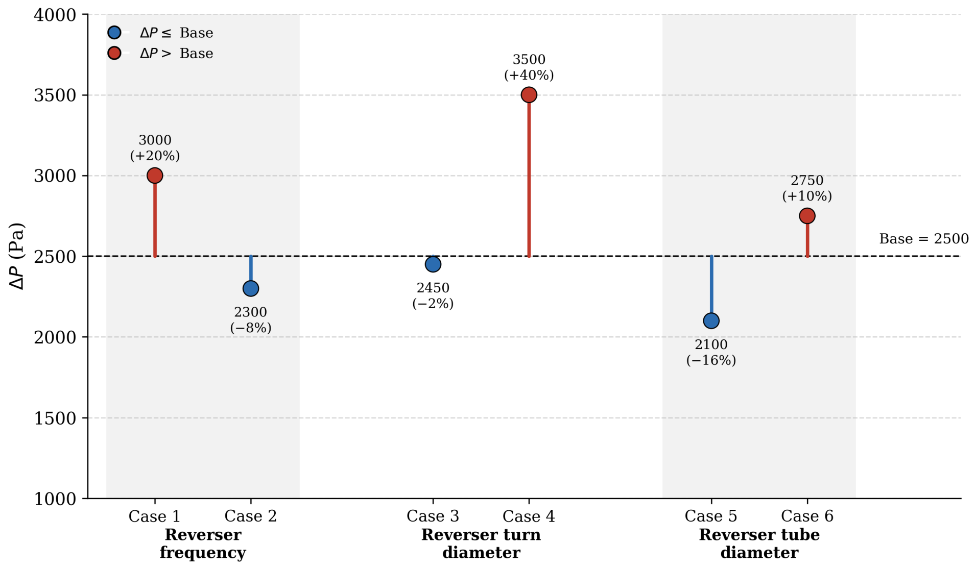
is essential for assessing the overall performance of the proposed reverser geometries. The base configuration (Case 7) exhibits a pressure drop of approximately 2500 Pa, which serves as the reference for all reported percentage changes.
The effect of reverser distribution frequency is evaluated through Cases 1 and 2 relative to the base model. Installing a reverser every half turn (Case 1) increases the pressure drop to approximately 3000 Pa, a 20% increase over the base model. Reducing the frequency to one reverser every two turns (Case 2), by contrast, lowers the pressure drop to approximately 2300 Pa, an 8% reduction relative to the base model, as the increased spacing allows the flow to recover over a longer distance and reduces hydraulic resistance while maintaining thermal performance similar to the base configuration.
The effect of reverser turn diameter is evaluated through Cases 3 and 4. Increasing the turn diameter (Case 3) results in a pressure drop of approximately 2450 Pa, slightly below the base model, since the smoother, larger-radius flow path weakens local acceleration and secondary vortices, reducing irreversible hydraulic losses. Decreasing the turn diameter (Case 4), conversely, produces the highest pressure drop among all configurations, approximately 3500 Pa, a 40% increase relative to the base model. Although this configuration enhances thermal mixing, as shown in
Figure 8, it also imposes the largest hydraulic penalty of all cases considered.
The effect of reverser tube diameter is evaluated through Cases 5 and 6. Increasing the tube diameter (Case 5) enlarges the internal flow passage of the reverser, lowering the average fluid velocity and reducing frictional losses. This configuration exhibits the lowest pressure drop among all investigated cases, approximately 2100 Pa, a 16% reduction relative to the base model. Decreasing the tube diameter (Case 6), conversely, reduces the available flow area, increasing local velocity and wall friction, and yields a pressure drop of approximately 2750 Pa, a 10% increase over the base configuration.
4.6. Effect of Reverser Geometry on PEC
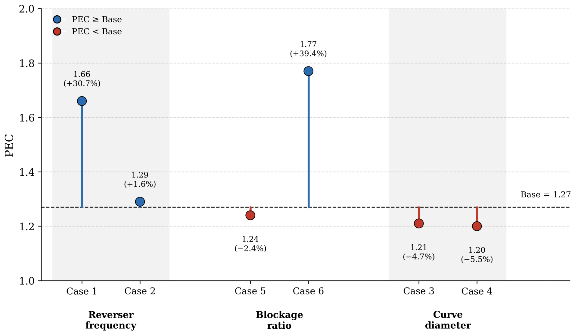
Figure 10 compares the performance evaluation criterion (PEC) of the investigated configurations. The PEC provides an integrated measure of thermo-hydraulic performance by simultaneously accounting for heat transfer enhancement and the associated pressure-drop penalty [
33], calculated using the following expression [
34]:
For the base model (Case 7), the value of the PEC is approximately equal to 1.27, which forms the basis of all percentages of improvements presented herein.
The effect of reverser distribution frequency is evaluated through Cases 1 and 2. Installing a reverser every half turn (Case 1) yields a PEC of approximately
, a
improvement over the base model, confirming that increasing the reverser frequency improves overall performance when the resulting heat-transfer enhancement (
Figure 8) is large enough to offset the accompanying rise in pressure drop (
Figure 9). Reducing the frequency to one reverser every two turns (Case 2), yields a PEC of approximately
. Although this configuration produces the same average Nusselt number a lower pressure drop than the base model, made it more efficient than the base model. As can be observed, it confirms that increased frequency of the reversers leads to better performance if the heat transfer enhancement (
Figure 8) outweighs the increase in pressure drop (
Figure 9). The use of one reverser every two spiral turns (Case 2) yields a PEC value that is close to that of the base model. Although this configuration reduces the pressure drop compared with the base design, the large spacing of reverser disturbances limits the heat transfer enhancement. Therefore, decreasing the spacing between consecutive reversers, as in Case 1, provides a more effective thermo-hydraulic optimization strategy.
The effect of reverser turn diameter is examined using Cases 3 and 4. The PEC value of approximately is obtained for Case 3, where the larger reverser turn diameter is used, while Case 4, where the smaller reverser turn diameter is applied, provides the minimal value of the PEC among all considered cases, approximately . In spite of the fact that sharper curvatures in Case 4 cause a higher secondary motion and marginally improve the Nusselt number in comparison with the base design, it results in the maximal pressure drop among all considered designs. Consequently, considering both heat-transfer enhancement and hydraulic losses, the base configuration represents the optimum reverser turn diameter.
Cases 5 and 6 are used to assess the effect of reverser tube diameter on the heat exchanger performance. Case 6, in which the smaller reverser tube diameter is utilized, shows the maximum PEC among all considered cases, which is equal to approximately , or 39.4% of improvement over the base design. It confirms the good balance between enhanced heat transfer and reduced hydraulic resistance. Case 5, where the larger reverser tube diameter is used, results in the PEC of approximately . In this case, the enlargement of the flow area substantially reduces the pressure drop.
4.7. Practical Implications of the Optimized Reverser Design
Beyond the parametric comparison presented above, it is useful to translate the observed improvements into their practical significance for heat exchanger design and operation. Because the hydraulic diameter of the flow passage was held constant across all investigated geometries (
Section 2), the local convective heat transfer coefficient
scales directly with the average Nusselt number. Case 6 (reduced reverser tube diameter) therefore provides an approximately 44.6% higher convective heat transfer coefficient than the base design (Case 7), for only a 10% increase in pressure drop and, consequently, pumping power. This trade off can be interpreted more directly through the performance evaluation criterion already used above (Equation (
7)), which by construction re-normalizes the heat-transfer and friction data onto a common, constant-pumping-power basis. Since
compared with
for the base design, Case 6 is expected to deliver approximately 39.4% higher tube side heat transfer coefficient than the base design when both are operated at the same pumping power. This has two practical consequences: (i) in a retrofit where the circulation pump cannot be resized, replacing the base reverser geometry with that of Case 6 would allow more heat to be recovered without any increase in pumping cost; (ii) where a fixed heat duty must be maintained, the same substitution would allow the pump to be operated at reduced power, lowering the electricity cost of fluid circulation over the exchanger’s service life.
Two scope limitations should be noted. First, the Nu, h, and PEC values compared here characterize the tube side convective resistance in isolation; this study does not report the shell side coefficient or the overall heat transfer coefficient, so the fraction of this tube side gain that is realized as additional overall duty depends on how resistive the shell side and tube wall are in a given installation. Second, the constant-pumping-power comparison embodied in PEC assumes the exchanger is not already operating in a high effectiveness regime, where further increases in heat transfer coefficient would yield diminishing returns in delivered duty. A complete assessment, including the shell side coefficient, exchanger effectiveness, and a full techno-economic analysis (capital cost, electricity tariffs, duty cycle), is beyond the scope of the present numerical study. Nonetheless, because the tube side enhancement (44.6%) substantially outweighs the hydraulic penalty (10%), the results indicate that, among the parameters considered, reducing the reverser tube diameter offers the most favorable balance between heat-transfer benefit and pumping-power cost.




 ,
,