


Abstract
Virtual synchronous generator (VSG) control is widely used to improve the frequency stability of low-inertia microgrids. However, most existing adaptive VSG strategies tune the virtual inertia and damping coefficient mainly according to local frequency deviations of the energy storage converter, while the effect of supplementary wind turbine frequency support on the admissible VSG parameter range is rarely considered. To address this limitation, this paper proposes a wind–storage coordinated frequency control strategy that combines an energy storage fuzzy VSG with active-power-frequency droop support from a doubly fed induction generator (DFIG). The scientific contribution of this study is that the DFIG droop support term is incorporated into a reduced-order wind–storage small-signal model, and an admissible scheduling region for the virtual inertia and damping coefficient is constructed according to prescribed damping ratio and natural angular frequency constraints. This region is used to constrain the online fuzzy parameter scheduling of the energy storage VSG. In addition, bell-shaped membership functions are introduced to obtain smoother parameter variation and are compared with triangular membership functions under the same operating conditions. MATLAB/Simulink simulations are conducted under grid-connected/islanded transition, load switching, and renewable-power fluctuation conditions. Compared with the benchmark strategies, the proposed method reduces the maximum and average frequency deviations to 0.181 Hz and 0.016 Hz, respectively. The maximum discharge power, RMS power, and cumulative energy throughput of the energy storage system are reduced to 236.853 kW, 155.822 kW, and 5.751 kWh, respectively. These results indicate that the proposed coordinated strategy improves frequency regulation while reducing the transient regulation burden of the energy storage system within the investigated operating conditions.
1. Introduction
With the proposal of the “dual carbon” goals (carbon peaking and carbon neutrality), the penetration rate of new energy sources, represented by wind and solar power, is progressively increasing in the power system [1]. As a key technological form of the new-type power system that integrates distributed generation, energy storage, loads, and intelligent control, the microgrid represents a core pathway for promoting the flexible, efficient, and large-scale utilization of new energy. Compared to the conventional power grid, microgrids offer robust support for power supply by flexibly switching between grid-connected and islanded modes. This dual-mode capability not only allows for optimized energy dispatch when connected to the main grid but also ensures the continuity of power supply through local control during islanded operation [2]. However, as the penetration of new energy sources continues to rise, the large-scale integration of wind and solar power, which are characterized by low inertia and weak damping, directly weakens the frequency support capability of the system. Particularly when the microgrid encounters sudden disturbances such as grid-connected/islanded mode transitions or load switching, the lack of sufficient inertial support makes it highly susceptible to issues like excessive frequency fluctuations, prolonged regulation times, or even frequency instability. This poses a severe challenge to the safe and reliable operation of the microgrid [3,4].
Virtual synchronous generator control enables a grid-forming converter to emulate the swing dynamics and damping characteristics of a synchronous generator. In this control structure, the virtual inertia J determines the relationship between the instantaneous active-power imbalance and the rate of change in angular frequency, whereas the damping coefficient D mainly affects the attenuation of frequency and power oscillations. At the onset of a disturbance, a larger J reduces the rate of change in frequency and therefore improves the initial inertial response. The active power required for this response is physically supplied or absorbed by the energy storage system. For instance, Zhong et al. [5] proposed a VSG-based control strategy for grid-connected/islanded mode transitions in microgrids, which demonstrates excellent power tracking capabilities and achieves a seamless switch between different operating modes of the microgrid. Building upon this foundation, Sahoo et al. [6] introduced this control strategy into a photovoltaic/storage/fuel cell microgrid, further validating the effectiveness of VSG control. To address the voltage and frequency stability issues caused by the high penetration of new energy sources in the power grid, Abid et al. [7] introduced VSG control into a photovoltaic power station equipped with energy storage, verifying the capability of VSG control in regulating voltage and frequency. The authors of the aforementioned literature all employed the VSG control strategy in their research. Although they effectively validated the potential of VSG control, it possesses an inherent limitation: fixed virtual inertia and damping parameters make it difficult to simultaneously satisfy the conflicting requirements of dynamic response speed and stability in a microgrid. Specifically, during the initial phase of a disturbance caused by a sudden change in the microgrid’s operating conditions, a larger inertia is beneficial for suppressing the rate of change in frequency, but it may lead to power oscillations. Conversely, the damping introduced to suppress these oscillations might slow down the system’s regulation speed.
Therefore, to overcome the deficiencies of conventional VSG control, adaptive control strategies that can adjust VSG parameters in real time based on frequency deviation and its rate of change are gradually gaining attention [8]. For example, Ren et al. [9] proposed an adaptive VSG control strategy with varying parameters specifically for scenarios involving significant voltage sags, which effectively reduces power and frequency fluctuations under large disturbances. Xu et al. [10] proposed a pre-synchronization method for inverter-based microgrids based on VSG parameter optimization, which achieves a smooth transition between grid-connected and islanded modes. Gurski et al. developed a VSG in which the virtual inertia and damping coefficient are jointly adapted to improve the transient frequency response of microgrids [11]. Shi et al. further analyzed the coordinated adjustment of inertia and damping over the oscillation process and proposed an adaptive optimal parameter control strategy [12]. Koiwa et al. proposed an online optimization approach that determines an appropriate inertia–damping combination while explicitly considering the converter current limit [13]. These approaches allow different parameter values to be assigned during different stages of a disturbance and therefore provide greater flexibility than conventional fixed-parameter VSG control. Recent studies have further investigated the coordinated adaptation of virtual inertia and damping to improve the transient frequency response of microgrids. Nevertheless, many existing methods rely on predefined switching thresholds, piecewise functions, exponential functions, or offline-optimized parameter relationships. Their performance may therefore depend on the selected operating point and parameter settings. Moreover, the admissible parameter ranges are commonly determined from an individual VSG model without explicitly considering supplementary frequency support from other controllable renewable energy units.
To reduce the dependence of control strategies on precise mathematical models of the system, adaptive control strategies based on intelligent algorithms, such as fuzzy logic, have been developed. A significant advantage of these methods is fuzzy-logic-based methods do not require an explicit high-order analytical model during online inference and can accommodate nonlinear and uncertain operating conditions. For example, Zhang et al. [14,15] employed fuzzy control to achieve adaptive adjustment of VSG parameters, which improved the system’s anti-interference capability and effectively enhanced the transient stability of the microgrid. Zhao et al. [16] proposed an inertia-adaptive control strategy that incorporates fuzzy control considering energy storage constraints. This strategy adjusts the virtual inertia based on the state of charge (SOC) of the energy storage module, effectively suppressing frequency fluctuations and overshoot. Teng et al. [17] proposed a power oscillation suppression strategy for VSG based on adaptive fuzzy sliding mode compensation, which can mitigate power oscillations during VSG operation. Existing fuzzy VSG studies have mainly focused on fuzzy-rule design, parameter range selection, state of charge constraints, and combinations with optimization or nonlinear compensation methods. However, two limitations remain insufficiently addressed in existing adaptive VSG studies. First, comparatively little attention has been paid to the influence of membership function shape on the smoothness of online parameter commands under otherwise identical controller settings. Triangular membership functions are piecewise linear and may produce relatively abrupt transitions between adjacent linguistic subsets, whereas bell-shaped functions provide smoother continuous transitions. Second, most studies treat the energy storage VSG as the primary frequency regulation unit and determine the admissible ranges of virtual inertia and damping mainly from an individual VSG model or local frequency indices, without explicitly considering supplementary active-power support from other controllable resources. In practice, DFIG-based wind turbines can participate in fast frequency response through rotor kinetic energy release, active-power reserve, or supplementary active-power-frequency control, thereby sharing part of the transient regulation burden imposed on the energy storage system [18].
Considerable research has been conducted worldwide on the coordinated participation of wind power and energy storage in system frequency regulation. In [18], droop control considering the state of charge of the energy storage system was combined with adaptive inertia control of the wind turbine, enabling both wind power and energy storage to participate in primary frequency regulation and thereby improving the system frequency response. Tu et al. [19] proposed a flexible power allocation method capable of adaptively adjusting the output power of wind power and energy storage, which achieved coordinated wind–storage frequency regulation while reducing wind power curtailment. Miao et al. [20] developed a coordinated control strategy for wind turbine generators and energy storage devices, in which the energy storage system compensated for the insufficient transient frequency support capability of the wind turbine, thereby improving the system frequency dynamics following disturbances. Zhang et al. [21] further applied fuzzy logic to the frequency control of wind farms and energy storage systems. The active-power outputs of the two systems were adjusted according to frequency deviation indices, demonstrating the effectiveness of intelligent control methods in coordinated fast frequency response involving wind power and energy storage. In [22], a coordinated frequency control strategy was proposed for permanent-magnet synchronous generator-based wind turbines and battery energy storage systems. By exploiting the complementarity between the rotor kinetic energy of the wind turbines and the fast bidirectional regulation capability of the energy storage system, the strategy improved the frequency nadir and the subsequent frequency-recovery process. Lin et al. [23] employed battery energy storage to compensate for the active-power deficit during the rotor speed recovery stage of the wind turbine, thereby mitigating the secondary frequency drop during the recovery process. More recently, Shu et al. proposed a wind–storage coordinated control strategy for enhancing system inertia under high renewable energy penetration, demonstrating the complementary inertia-support capability of wind turbines and energy storage [24]. Pei et al. developed a hierarchical wind–storage frequency support strategy that also considers post-disturbance state of charge recovery and arbitrage revenue, extending coordinated frequency control toward multi-timescale operational objectives [25]. Shu et al. also proposed a variable-coefficient coordination strategy based on wind speed and energy storage SOC, allowing the frequency support contribution of each resource to adapt to changing operating conditions [26]. These studies demonstrate the potential of wind–storage coordination to improve frequency response and distribute the regulation demand among multiple resources. However, most existing wind–storage coordination methods focus on active-power allocation or the independent design of local control loops. Relatively limited attention has been paid to incorporating the DFIG supplementary droop coefficient into the admissible J-D combinations of the energy storage VSG. Consequently, the parameter limits used by the fuzzy VSG may not reflect the change in coordinated system dynamics after wind power participates in frequency regulation. Establishing this relationship is therefore necessary for coordinating VSG parameter scheduling with wind turbine transient power support.
Overall, three technical and scientific limitations motivate this study. First, many adaptive VSG methods determine the admissible ranges of the virtual inertia J and damping coefficient D using an individual VSG model, predefined thresholds, empirical functions, or offline-optimized parameter relationships. These parameter ranges do not explicitly include the influence of supplementary frequency support from wind turbines. Second, existing wind–storage coordinated control studies mainly address active-power allocation, rotor kinetic energy utilization, state of charge management, and local controller design. The relationship between the DFIG active-power-frequency droop coefficient and the dynamic-performance constraints of the storage-side VSG requires further investigation. Third, many studies evaluate frequency nadir, maximum frequency deviation, and recovery performance without simultaneously quantifying the transient regulation burden imposed on the BESS. The coordinated relationships among DFIG frequency support, online J-D scheduling, frequency response performance, and BESS power and energy demand therefore require a unified analysis. Based on these limitations, this study addresses the following research question: can supplementary DFIG active-power support and constrained adaptive VSG parameter scheduling be coordinated to improve the frequency response of a high-renewable microgrid while reducing the transient regulation burden imposed on the BESS? The working hypothesis is that incorporating the DFIG droop support term into a reduced-order wind–storage model and constraining the online J-D combinations through prescribed damping ratio and natural angular frequency ranges can reduce frequency deviations and improve transient recovery. The supplementary DFIG active-power response is also expected to share part of the transient power imbalance, thereby reducing the peak power, RMS power, and cumulative energy throughput required from the BESS under the investigated operating conditions. To examine this hypothesis, this study develops a coordinated wind–storage frequency control strategy combining an energy storage fuzzy VSG with supplementary DFIG active-power-frequency droop control. First, a reduced-order wind–storage small-signal model is established by incorporating the DFIG droop support term. The model describes the relationships among the virtual inertia J, damping coefficient D, DFIG droop coefficient, damping ratio, and natural angular frequency. An admissible J-D region is then constructed according to the prescribed damping ratio and natural angular frequency ranges, providing a system-level dynamic basis for constraining the online parameter combinations. Second, a constrained fuzzy scheduling mechanism is designed to adjust J and D within the admissible region. Triangular and bell-shaped membership functions are implemented under the same input variables, fuzzy rules, scaling factors, and parameter ranges to evaluate their influence on the smoothness of the online parameter commands. Third, supplementary DFIG active-power support is coordinated with the storage-side fuzzy VSG, enabling the wind turbine to supply part of the transient active-power deficit and share the frequency regulation demand with the BESS. Finally, six controlled comparison cases are established to identify the individual and combined effects of fixed-parameter VSG control, adaptive J-D scheduling, membership function selection, and DFIG frequency support. The maximum and mean frequency deviations, BESS peak power, RMS power, and cumulative energy throughput are used to evaluate the frequency regulation performance and storage regulation burden. The main scientific contribution of this study is the establishment of a system-level relationship between supplementary DFIG frequency support and the admissible J-D combinations of the storage-side VSG, which provides a theoretical basis for constrained VSG parameter scheduling and coordinated wind–storage transient power support.
2. Materials and Methods
2.1. System Configuration of the Wind–Solar–Storage Microgrid
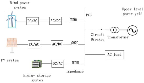
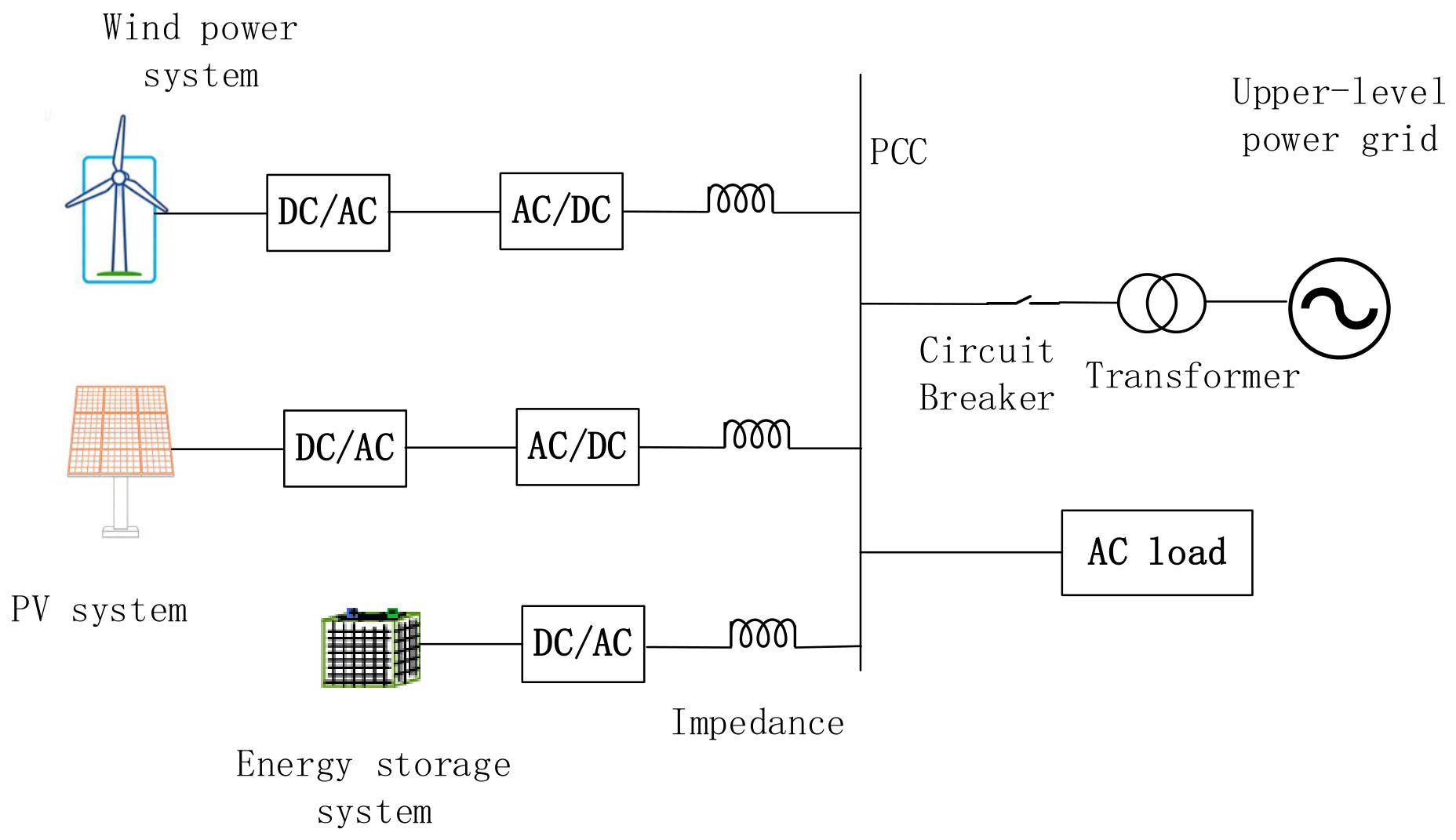
A wind–solar–storage AC microgrid was developed in MATLAB/Simulink R2023b (MathWorks, Natick, MA, USA), as shown in Figure 1. The system can operate in either grid-connected or islanded mode and consists of a 2 MW DFIG-based wind power system, a 1 MW PV system, a 1 MWh energy storage system, loads, and the upstream grid, all connected to the point of common coupling through transformers. The DFIG rotor-side converter adopts power/current dual-loop control, whereas the grid-side converter adopts voltage/current dual-loop control. The energy storage system provides controllable active-power support to compensate for power imbalances caused by renewable-power fluctuations and load variations.
Figure 1.
Schematic diagram of a wind–solar–storage microgrid structure.
The PV system operates under maximum power point tracking control and is treated as a grid-following source that does not directly participate in the proposed primary frequency control strategy. Therefore, irradiance-induced PV-power variations are modeled as external active-power disturbances, which are compensated by the energy storage VSG and the supplementary active-power-frequency droop loop of the DFIG. Accordingly, the internal PV-converter dynamics are not included in the reduced-order wind–storage small-signal model, while PV-power variations are retained in the complete nonlinear MATLAB/Simulink model to evaluate their influence on the microgrid frequency response.
2.2. Analysis of Basic Control Strategies
2.2.1. DFIG Rotor-Side Droop Control Modification
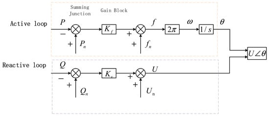
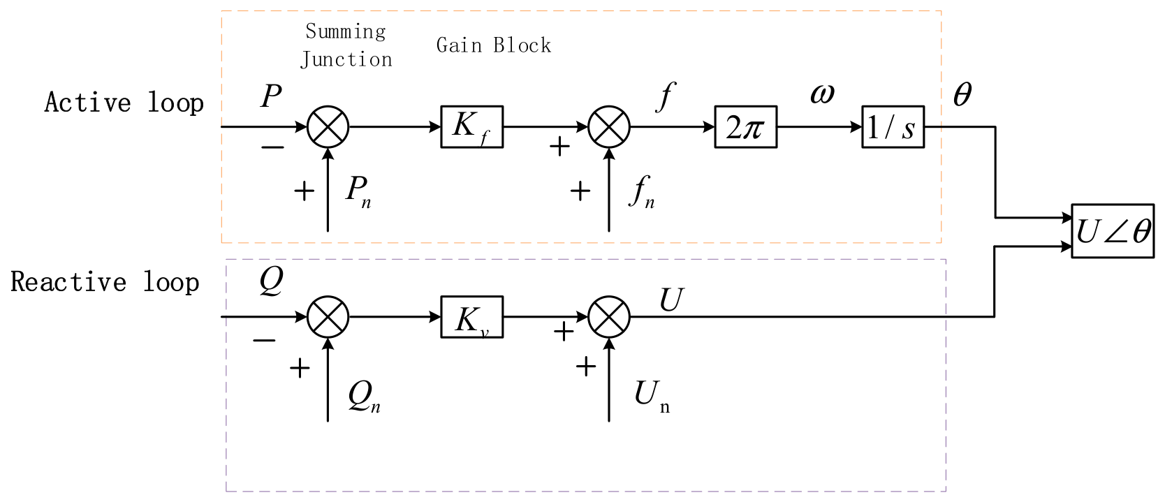
Figure 2 illustrates the active–reactive-power control block diagram for droop control.
Figure 2.
Droop control active–reactive-power control block diagram.
From the active and reactive-power loop block diagrams in Figure 2, the following can be derived:
where is the active-power droop coefficient and is the reactive-power droop coefficient.
Conventional wind turbine control generally prioritizes maximum power point tracking, and the wind turbine therefore contributes little to primary frequency regulation. During large load changes or renewable-power fluctuations, the resulting active-power imbalance is mainly compensated by the ESS. Although the ESS provides a rapid bidirectional response, its regulation capability is constrained by its rated power, energy capacity, and operating state. Consequently, relying primarily on the ESS increases its transient regulation burden and reduces the available power margin.
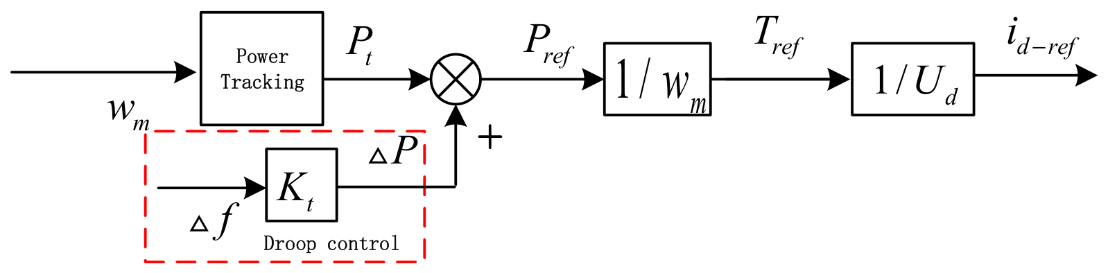
Modern DFIGs are interfaced through power-electronic converters, allowing their active-power output to be adjusted within the limits imposed by the available wind power, rotor speed range, converter current capacity, and operating reserve. Therefore, a supplementary active-power-frequency droop term can be introduced into the active-power outer loop of the rotor-side converter without changing the basic inner current control structure. In this study, the droop support term is superimposed on the original active-power reference, enabling the DFIG to provide supplementary transient frequency support and share part of the regulation demand imposed on the ESS. This modification can be implemented mainly through the existing converter control software, resulting in relatively low structural complexity and implementation cost [27].
The improved active-power outer loop is illustrated in Figure 3. In this figure, denotes the DFIG rotor speed, represents the output power from the power tracking module, and is the droop coefficient of the wind turbine. Additionally, and correspond to the output reference power and reference torque, respectively, while are the reference values for the rotor -axis voltage and current.
Figure 3.
Improved RSC power outer loop.
To avoid frequent activation of the supplementary frequency support loop under small frequency fluctuations, a deadband of 0.02 Hz is adopted in the studied system. When the absolute frequency deviation is below this threshold, the supplementary droop support power command is set to zero, while the original wind turbine power control loop continues to operate normally. When the frequency deviation exceeds the deadband, the wind turbine droop support loop and the energy storage fuzzy VSG are activated to jointly respond to the disturbance. This deadband reduces unnecessary control actions and helps limit parameter fluctuations caused by small frequency variations.
2.2.2. Virtual Synchronous Generator Control
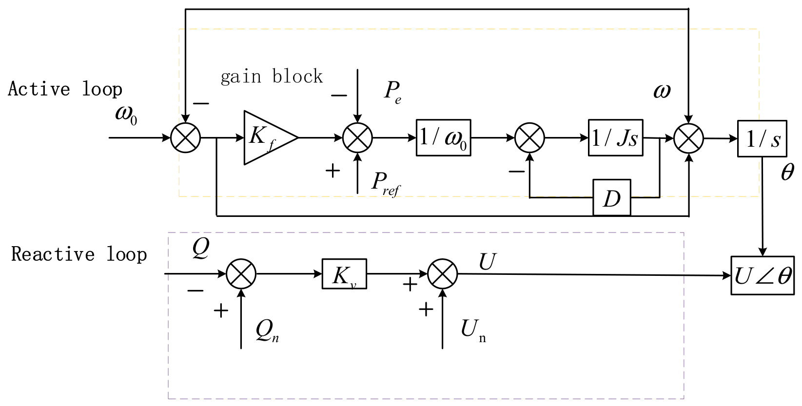
VSG control enables the energy storage converter to emulate the swing and damping characteristics of a synchronous generator, as shown in Figure 4.
Figure 4.
VSG active–reactive-power control block diagram.
The virtual governor control of the VSG is based on the rotor motion equation of a synchronous generator, and its basic mathematical model is described in [9].
where represent the mechanical power and electromagnetic power, respectively; is the virtual inertia, and is the damping coefficient. Since the mechanical power is composed of the active-power reference value and the power generated by primary frequency regulation, according to the active-power-frequency droop control, we can obtain the following:
by combining Equations (2) and (3) and applying the Laplace transform, we can obtain the following:
VSG control introduces a swing-equation-based dynamic relationship into the converter control system, allowing the energy storage converter to provide an inertial-type active-power response during a power imbalance. The resulting frequency response depends on the selected virtual inertia and damping parameters as well as on the available power and energy capacity of the storage system. Therefore, VSG control does not inherently provide superior performance under all operating conditions, and fixed parameters may lead to different compromises between RoCoF suppression, oscillation attenuation, and recovery speed.
In this study, fuzzy parameter scheduling is combined with supplementary DFIG droop support. The purpose is to coordinate the transient support provided by the wind turbine and the energy storage converter while maintaining the VSG parameters within prescribed dynamic-performance limits.
2.3. Small-Signal Modeling and Stability Analysis of Wind Power and Energy Storage Combined Systems
2.3.1. Establishment of the Wind–Storage Combined System Model
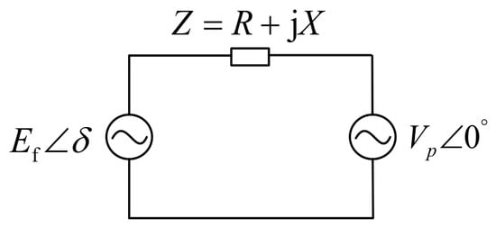
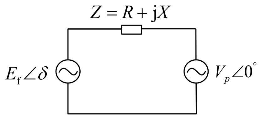
Figure 5 shows the grid-connected equivalent circuit diagram of the VSG. In the figure, is the output voltage of the VSG, is the equivalent line impedance, is the voltage at the PCC, and represents the phase angle difference between the two voltages. Since the impedance between the inverter output voltage and the PCC is predominantly inductive, the resistive component can be ignored.
Figure 5.
VSG grid-connected equivalent circuit diagram.
The active and reactive powers transferred between the VSG and the PCC are therefore expressed as follows:
These equations describe the steady-state power angle relationship but do not capture the dynamic influence of the virtual inertia and damping coefficient. Therefore, the model is linearized around the steady-state operating point to derive the reduced-order small-signal model used for stability analysis and VSG parameter design [9].
The relationship between angular velocity and power angle is given by the following:
Linearizing Equation (7) around the steady-state operating point yields ,
Let the synchronizing coefficient be , which is a constant. Therefore:
In the complex frequency domain, it is expressed as follows:
Due to the implementation of active-power-frequency droop control on the rotor side of the wind turbine generator, the unit provides an additional active-power compensation during system frequency fluctuations. Consequently, by treating the wind power support as an equivalent mechanical power input and linearizing Equation (2), the linearized model for the integrated wind–storage system is derived as follows:
Also, because
can obtain
applying the Laplace transform to Equations (7) and (13) yields the following:
Combining Equations (10), (14) and (15) finally yields the transfer function between the output power and the power reference value:
It should be emphasized that Equations (11)–(16) are obtained by linearizing the wind–storage system around a balanced steady-state operating point. The derivation assumes small deviations in frequency and power angle, approximately constant voltage magnitudes, a fixed network topology and operating mode, and sufficiently fast inner voltage and current control loops. Therefore, the stability conditions and pole locations derived from this model characterize only the local small-signal behavior of the reduced-order system near the selected operating point. They do not constitute a proof of global asymptotic stability for the complete nonlinear microgrid during large disturbances. In particular, an islanding event changes the network topology and operating equilibrium, and the linearized model does not describe the exact switching transient. The purpose of the small-signal analysis is to characterize the local oscillatory mode and provide physically interpretable constraints for the selection and online scheduling of J and D.
According to the Routh–Hurwitz stability criterion, the necessary and sufficient condition for the asymptotic stability of the system is that the equivalent damping coefficient is greater than 0, i.e., satisfying , which establishes the upper bound of the wind power droop coefficient . Considering that the fuzzy controller adaptively adjusts the damping coefficient within during transient processes, to ensure that negative damping instability does not occur under all operating conditions, must be satisfied. However, this inequality only excludes negative equivalent damping and therefore represents the minimum local stability requirement of the reduced-order model. It does not constitute a complete coordinated design boundary for J and D, nor does it by itself guarantee the stability of the full nonlinear system throughout the entire transient process. The coordinated parameter constraints are therefore further determined using the damping ratio and natural angular frequency requirements described below.
Based on the established transfer function, the dynamic characteristics of the VSG system can be quantitatively analyzed. The damping ratio and natural oscillation angular frequency serve as core indicators determining the system’s transient oscillation suppression capability and steady-state regulation accuracy; their expressions can be derived through equivalent transformation and parameter matching of the transfer function. The expression for the damping ratio is given by the following:
The expression for the natural oscillation angular frequency is given by the following:
The expression for the oscillation frequency is given by the following:
The expression for the peak time is given by the following:
The expression for the 2% settling time is given by the following:
The expression for the overshoot is given by the following:
where denotes the natural exponential function.
Under transient disturbances, the system closed-loop poles are located at the following:
By regarding the VSG small-signal system as a standard second-order system, its key indicators include the VSG’s oscillation frequency, peak time, 2% settling time, and overshoot. The damping ratio is a core parameter that determines the overshoot of the VSG transient response and the oscillation decay rate; the correlation between its value and the system’s dynamic characteristics can be quantified via the overshoot Equation (22). The damping ratio affects the overshoot and oscillation decay characteristics of the reduced-order second-order model. For example, a damping ratio of 0.4 corresponds to an overshoot of approximately 25%, whereas a damping ratio of 0.8 corresponds to an overshoot of approximately 1.5% under the standard second-order approximation. Based on these response characteristics and the transient-performance requirements adopted for the studied microgrid, the damping ratio interval is selected as . This interval is used as a design constraint in the present study. Different system ratings, network impedances, operating points, and converter limits may require the interval to be retuned. Accordingly,
The natural angular frequency affects the response speed of the reduced-order VSG model. A relatively low value corresponds to a slower transient response, whereas a relatively high value increases the sensitivity of the parameterized model to rapid variations. Considering the response speed and oscillation suppression requirements of the studied system, the natural angular frequency interval is selected as . This interval represents a system-specific design choice used to construct the admissible J-D region. Accordingly,
Based on the optimal ranges of the system damping ratio and the natural oscillation angular frequency, together with their relationships with the virtual inertia J and damping coefficient D, the per-unit range of the virtual inertia J is determined as , corresponding to an actual value range of .
Correspondingly, according to Equation (24), the per-unit range of the damping coefficient D is given by
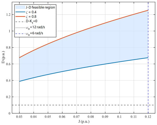
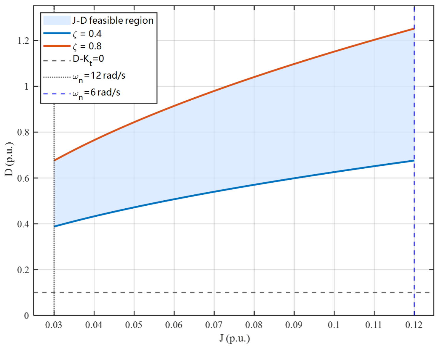
The above inequalities jointly define the J-D feasible region proposed in this study. The parameter commands generated by the fuzzy controller should always remain within this feasible region, thereby ensuring that both the system damping ratio and the natural oscillation angular frequency satisfy the predefined dynamic-performance requirements during the online adjustment process.
As shown in Figure 6, the natural angular frequency constraint limits the virtual inertia J to the per-unit range of 0.03–0.12. The two boundary curves correspond to damping ratios of 0.4 and 0.8, and the shaded region defines the feasible J-D combinations satisfying the prescribed requirements for response speed and oscillation attenuation. Because increasing J reduces the natural angular frequency and, for a fixed D, decreases the damping ratio, the allowable range of increases nonlinearly with J. Specifically, the feasible range of D is approximately 0.38–0.676 at J = 0.03 and 0.676–1.252 at J = 0.12. Therefore, J and D cannot be selected independently within their respective global bounds but must satisfy the coupled constraint given by Equation (26).
Figure 6.
J-D Feasible region of the wind–energy storage integrated system.
The asymptotic stability boundary lies below the constructed feasible region, indicating that all admissible parameter combinations satisfy the basic stability condition. However, this condition alone does not characterize the damping ratio, oscillation decay rate, or response speed. Therefore, the fuzzy controller outputs are constrained by the dynamic-performance region: for each online value of , the corresponding upper and lower limits of are calculated to ensure that the parameter trajectory remains within the feasible region.
2.3.2. Stability and Dynamic-Performance Constraints
Currently, numerous methods exist for analyzing VSG stability. To intuitively demonstrate the influence of different virtual inertia J and damping coefficients D on the operational stability of the microgrid, this paper analyzes the performance of the VSG under different parameters from three aspects: the root locus, unit step response, and phase margin.
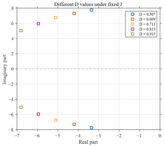
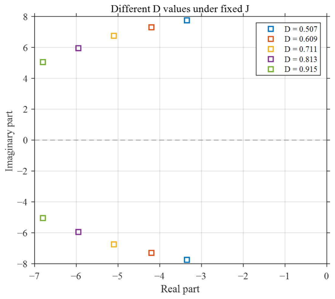
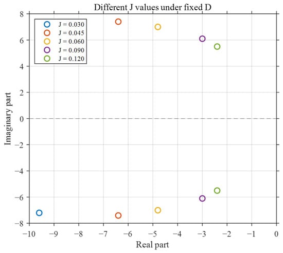
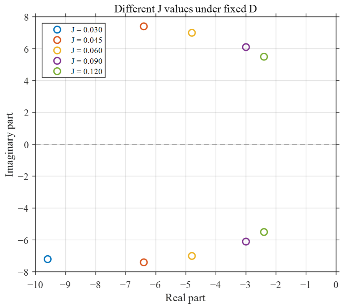
Figure 7 and Figure 8 show the closed-loop pole trajectories obtained by varying D at a fixed J and by varying J at a fixed D, respectively. As shown in Figure 7, increasing the damping coefficient moves the complex-conjugate poles toward the negative real axis and increases the damping ratio, thereby reducing the oscillatory characteristics of the system. However, when D becomes excessively large, the system enters an overdamped region, and the dominant pole gradually approaches the origin, resulting in a slower transient response.
Figure 7.
Variation in system root locus poles when J is fixed and D varies.
Figure 8.
Variation in system root locus poles when D is fixed and J varies.
Figure 8 illustrates the effect of the virtual inertia at a fixed damping coefficient. Within the investigated parameter range, increasing J reduces both the natural angular frequency and the real-part magnitude of the dominant poles. Consequently, the initial rate of change in frequency is reduced, but the oscillation decay rate and the overall response speed also decrease. Therefore, a larger virtual inertia improves the initial RoCoF suppression capability.
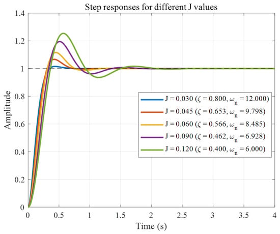
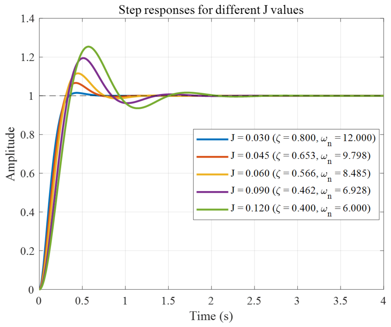
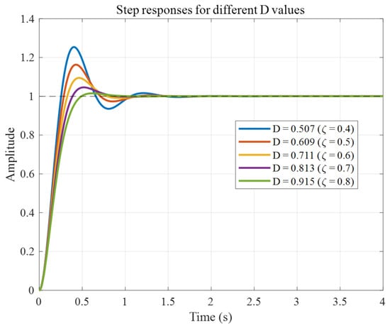
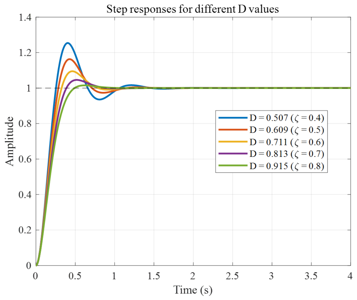
Figure 9 and Figure 10 further confirm these observations in the time domain. At a fixed D, increasing J reduces the initial response slope but generally increases the rise time, peak time, and settling time. At a fixed J, increasing D reduces the overshoot and improves oscillation attenuation within the underdamped region. Nevertheless, an excessively large D produces an overdamped and sluggish response.
Figure 9.
System unit step response when D is fixed and J varies.
Figure 10.
System unit step response when J is fixed and D varies.
2.4. Frequency Control Strategy for Microgrids Considering Wind–Storage Coordination
Wind–PV–energy storage microgrids controlled by VSG are prone to transient stability issues, specifically frequency fluctuations, during sudden changes in operating conditions such as switching between grid-connected and islanded modes or load switching. To address this, based on the previously determined value ranges for inertia J and damping D, this section first analyzes the system’s dynamic response to disturbances across five distinct stages to establish adjustment protocols for J and D. Subsequently, a fuzzy logic controller featuring an improved membership function is employed to achieve adaptive regulation of the VSG parameters. Finally, an active-power-frequency droop control module is integrated into the active-power outer loop of the rotor-side converter (RSC) of the DFIG. This enables the wind power unit to actively respond to microgrid frequency fluctuations, thereby establishing a coordinated frequency control strategy for the wind–storage microgrid.
2.4.1. Coordinated VSG Parameter Tuning
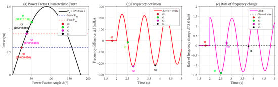
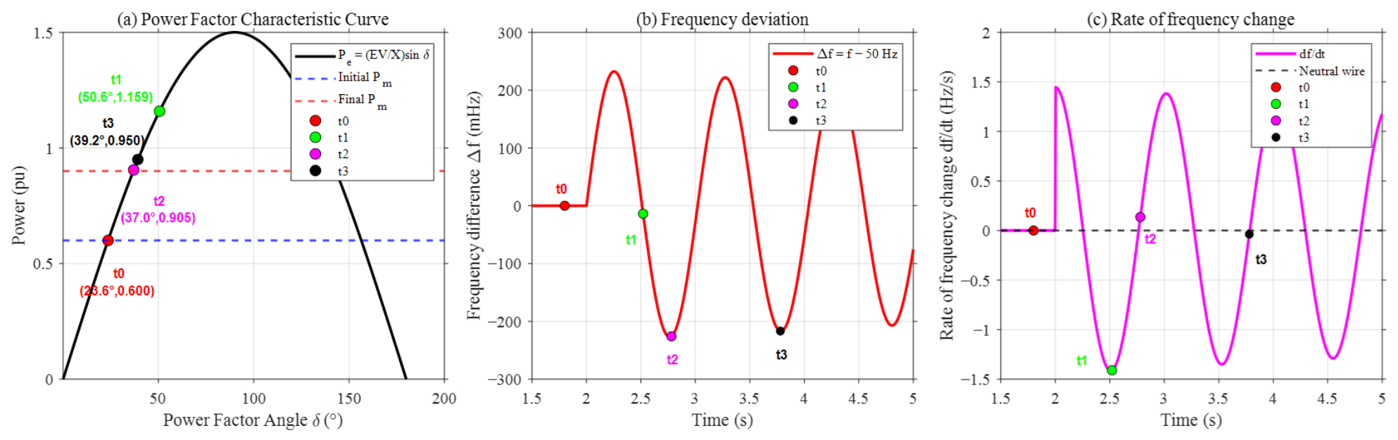
Figure 11 illustrates the characteristic curves of the microgrid’s power angle and frequency when it is subjected to disturbances caused by sudden changes in operating conditions, such as switching between grid-connected and islanded modes or load switching. Taking the power angle, frequency, and their rates of change during a sudden load increase as an example, the first oscillation cycle of the system is divided into five stages for analysis:
Figure 11.
System power and frequency response curves.
Stage 1 (Initial Stage):
Immediately after a sudden load increase, the active-power imbalance causes the frequency to decrease rapidly. At this instant, the frequency deviation is still relatively small, whereas the rate of change in frequency is negative and has a large magnitude. Therefore, J should be rapidly increased to reduce the initial RoCoF. Although the damping term has a limited instantaneous contribution because is initially close to zero, D should still be adjusted simultaneously according to the J-D feasible region. This coordinated adjustment prevents the damping ratio from decreasing excessively as J increases.
Stage 2 (Accelerated Deceleration Stage):
In this stage, the power angle of the system increases, the frequency continues to drop, and the rate of change in frequency remains negative, but its absolute value decreases. This is a stage where the rotor continuously decelerates and kinetic energy is converted into electromagnetic energy. At this time, the system’s virtual inertia J should slowly drop from a high value to a medium level to prevent excessive inertia from affecting the subsequent recovery; the system’s damping coefficient D should be increased to suppress system oscillations.
Stage 3 (Reaching the Maximum Power Angle):
At the frequency nadir, the RoCoF approaches zero. The primary requirement for a large virtual inertia is therefore weakened. Accordingly, J should be reduced from its high value to a moderate value. Meanwhile, D should be maintained at a relatively high but feasible level to suppress the subsequent oscillatory response.
Stage 4 (Recovery Acceleration Stage):
When the frequency remains below the rated value but the RoCoF becomes positive, the frequency is returning toward its nominal value. In this condition, and have opposite signs. Therefore, J should be reduced to accelerate frequency restoration and prevent excessive inertia from prolonging the recovery process. The damping coefficient should be adjusted to a moderate level within the feasible region to limit the subsequent overshoot.
Stage 5 (Swing-back Stage):
After the frequency crosses its rated value, a condition with and indicates that the frequency is returning toward the rated value from the opposite side. Under this condition, J should remain relatively small to facilitate rapid restoration. Only when and acquire the same sign again, indicating that a secondary frequency excursion is developing, should J be increased to suppress the renewed rate of frequency departure. The damping coefficient should simultaneously be adjusted within the feasible region to attenuate the secondary oscillation.
2.4.2. Adaptive Adjustment of VSG Parameters Based on Fuzzy Logic Control
Fuzzy Logic Control (FLC) leverages fuzzy rules and logical reasoning to achieve smooth and highly adaptive control for nonlinear, strongly coupled, and time-varying systems. In this study, a fuzzy logic controller is designed using frequency deviation and the rate of change in frequency as inputs. Guided by the parameter tuning principles established in Section 4.1, the controller adaptively adjusts the virtual inertia J and damping coefficient D of the VSG. The specific fuzzy rules are detailed in Table 1 and Table 2.
Table 1.
Fuzzy logic for virtual inertia J.
Table 2.
Fuzzy logic for damping coefficient D.
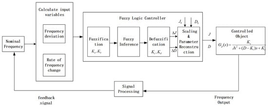
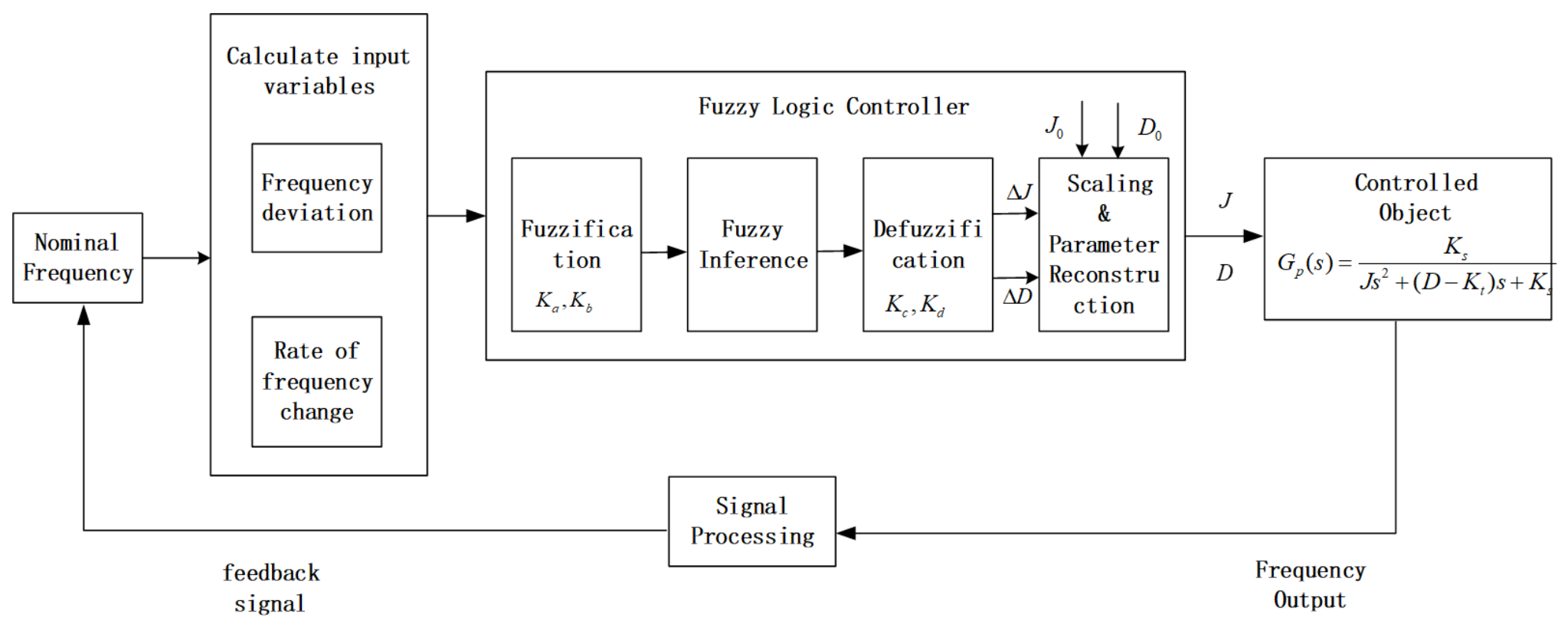
Figure 12 illustrates the customized, closed-loop block diagram of the proposed adaptive fuzzy VSG control system. As shown, the frequency deviation Δf and the rate of change in frequency df/dt are calculated from the grid frequency in the input calculation block, where serve as the quantization factors to convert these crisp inputs into normalized fuzzy inputs for the controller. Within the fuzzy logic controller block, these inputs undergo fuzzification (using the proposed bell-shaped membership functions), fuzzy inference, and defuzzification. Conversely, act as the scaling factors in the parameter reconstruction block, converting the fuzzy outputs into physical parameter increments ΔJ and ΔD, which are superimposed onto the initial parameters J0 and D0 to generate the real-time virtual inertia J and damping coefficient D. These adaptive parameters are then fed into the controlled object representing the closed-loop system dynamics in Equation (21), with the frequency output looped back through the signal processing block to form a complete closed-loop feedback loop.
Figure 12.
Structure of the fuzzy logic controller.
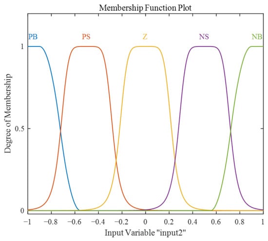
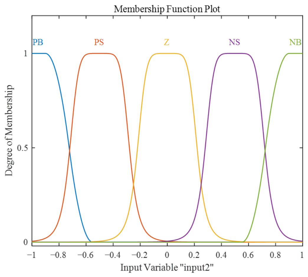
Triangular membership functions have low computational complexity and are straightforward to implement. However, their piecewise linear form introduces slope discontinuities at the vertices, which may result in less smooth parameter transitions when the fuzzy inputs cross adjacent linguistic regions. Bell-shaped membership functions provide a smoother variation in the membership degrees and are therefore adopted in this study to improve the continuity of the online parameter commands. The use of bell-shaped membership functions is expected to reduce abrupt variations in J and D, but it does not by itself guarantee the complete elimination of parameter fluctuations. Accordingly, their effect is assessed by comparison with triangular membership functions under the same fuzzy rules and disturbance scenarios. The specific membership functions are illustrated in Figure 13.
Figure 13.
Membership functions for inputs and outputs.
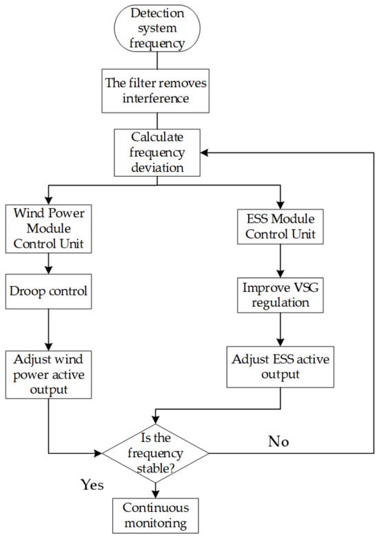
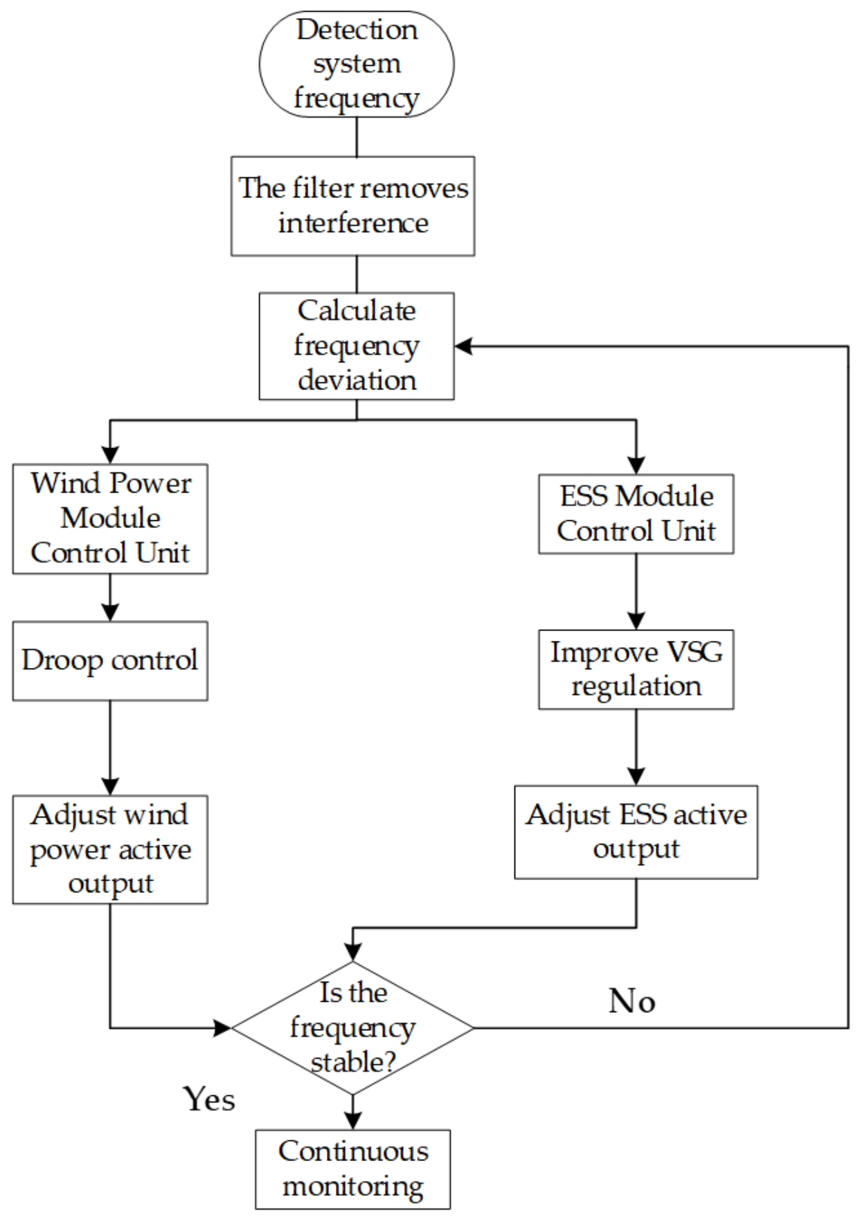
In summary, utilizing microgrid frequency variations as a reference, this paper introduces droop control into the DFIG to fully leverage its frequency regulation potential. Together with energy storage devices, this forms a coordinated wind–storage frequency regulation system, the specific process of which is illustrated in Figure 14.
Figure 14.
Flowchart of the coordinated wind–storage microgrid frequency control.
First, the microgrid bus frequency signals are collected by distributed frequency monitoring units. High-frequency interference is eliminated via first-order low-pass filtering to precisely extract the frequency deviation. Next, this frequency deviation is synchronously transmitted to both the wind power module control unit and the energy storage system control unit, triggering a coordinated frequency regulation mechanism. For the wind power module, based on the active-power outer loop droop control strategy of the DFIG’s RSC, the frequency deviation is input into the droop control model. This generates an active-power reference command that incorporates frequency regulation demands, thereby enabling the rapid output of regulating active power. Simultaneously, for the energy storage system, charge and discharge regulation commands are dynamically generated based on the frequency deviation and the real-time active-power output feedback from the wind power module. Through the synchronous regulation of the wind power module and the energy storage system, microgrid frequency fluctuations are suppressed in real time.
2.5. Simulation Setup, Benchmark Cases, and Evaluation Metrics
In this paper, the microgrid model illustrated in Figure 1 was constructed using Matlab/Simulink; the key simulation parameters are listed in Table 3 and Table 4. To intuitively analyze the system frequency fluctuations under scenarios such as mode switching between grid-connected and islanded operation, sudden changes in renewable energy generation, and load switching, the simulation scenarios are configured as follows:
Table 3.
Simulation parameter settings.
Table 4.
Specifications and parameters of the microgrid components.
The total simulation duration is set to 4 s. The initial active-power output is set to 0.5 MW for wind power and 0.75 MW for photovoltaic (PV) power, while the initial active load of the microgrid is 1.3 MW.
- At the beginning of the simulation, the system operates in the grid-connected mode, with each generation system outputting active power according to the given setpoints;
- At 0.5 s, the microgrid undergoes a transition from grid-connected to islanded mode;
- At 1.5 s, due to load switching operations, the system’s active load decreases to 1 MW;
- At 2.5 s, accounting for variations in solar irradiance, the active-power output of the PV system decreases to 0.4 MW. Because the PV system remains under MPPT control, it does not provide supplementary frequency support. The energy storage VSG therefore responds to the resulting power imbalance, while the DFIG droop loop shares part of the transient active-power demand. This result demonstrates the capability of the proposed wind–storage coordinated strategy to accommodate external power disturbances caused by PV output variations.
Among them, the grid and physical network parameters (e.g., ) are selected according to standard low/medium-voltage industrial microgrid specifications. The nominal frequency of 50 Hz naturally corresponds to , and the line reactance is a typical inductive line impedance in distribution networks.
The DC-link voltage specifications () are designed based on the modulation constraints of a two-stage three-phase grid-connected inverter. To output the rated line-to-line voltage of 600 V under space vector PWM (SVPWM) without overmodulation, the minimum DC bus voltage must be greater than . Therefore, setting the DC bus voltage between 922 V and 1000 V is standard engineering practice.
Initial VSG parameters (): the initial values of J and D are selected strictly in accordance with the stable parameter range derived in Section 3 of our paper. The selection of the droop gains is to satisfy the standard primary frequency droop requirements, ensuring that the maximum frequency deviation remains within the grid code limits.
Fuzzy scaling and quantization factors (): the selection of these factors is based on the domain mapping between the physical inputs/outputs and the normalized fuzzy universes of discourse. The quantization factors scale the frequency deviation and the rate of change in frequency to the fuzzy boundaries. The scaling factors scale the normalized fuzzy outputs back to the physical parameter adjustment ranges, guaranteeing that the adjusted J and D limit the adjusted and to the prescribed ranges. These four factors were not obtained using a numerical optimization algorithm. They were initially selected according to the mapping between the expected physical ranges of the frequency deviation, RoCoF, virtual inertia increment, and damping coefficient increment and their normalized fuzzy universes. A limited number of trial simulations were then performed to avoid prolonged input saturation and abrupt parameter variations.
To verify the effectiveness of the proposed microgrid frequency control strategy considering wind–storage coordination, the following six comparative scenarios are established:
- Scenario 1: the energy storage system (ESS) adopts traditional droop control.
- Scenario 2: the ESS adopts traditional VSG control.
- Scenario 3: the ESS adopts fuzzy VSG control based on triangular membership functions.
- Scenario 4: the ESS adopts fuzzy VSG control based on bell-shaped membership functions.
- Scenario 5: the ESS adopts fuzzy VSG control based on triangular membership functions, while the wind power side additionally introduces droop control to form a coordinated wind–storage frequency regulation scheme.
- Scenario 6: the ESS adopts fuzzy VSG control based on bell-shaped membership functions, while the wind power side additionally introduces droop control to form a coordinated wind–storage frequency regulation scheme (i.e., the proposed method).
To isolate the incremental effects of VSG control, fuzzy parameter scheduling, membership function shape, and supplementary DFIG frequency support, six benchmark scenarios are established. All scenarios use the same microgrid topology, equipment ratings, initial operating point, disturbance sequence, simulation interval, and performance-index definitions. Scenarios 1 and 2 provide the conventional droop and fixed-parameter VSG baselines; Scenarios 3 and 4 compare triangular and bell-shaped fuzzy VSG control; and Scenarios 5 and 6 introduce supplementary DFIG droop support under the corresponding fuzzy-control configurations.
3. Results
3.1. Analysis of Microgrid Power Simulation Results
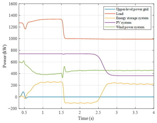
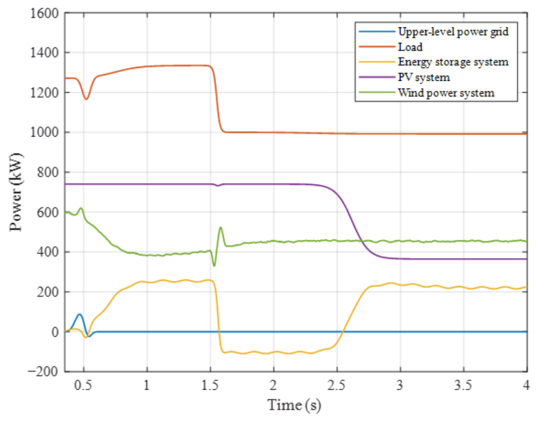
Under the simulation scenarios established in this paper, the time domain simulation results of the power variations for the wind power system, PV system, energy storage system, and load are illustrated in Figure 15.
Figure 15.
Active-power output of system modules.
As shown in Figure 15, during the initial grid-connected operation stage, the upstream grid absorbs or injects active power to accommodate fluctuations in wind and PV output, thereby maintaining the system’s power balance. During this phase, the ESS is not required to output significant active power but continues to provide ancillary regulation support for system frequency stability.
At 0.5 s, the microgrid transitions to islanded operation. Consequently, the ESS begins providing frequency and voltage support and injects active power to maintain power balance.
At 1.5 s, the load decreases by 0.3 MW. As a result, the ESS switches from injecting active power to absorbing active power (i.e., charging).
At 2.5 s, the output of the PV system gradually decreases from 0.75 MW to 0.4 MW. Therefore, the ESS reverts from absorbing active power to injecting active power once again.
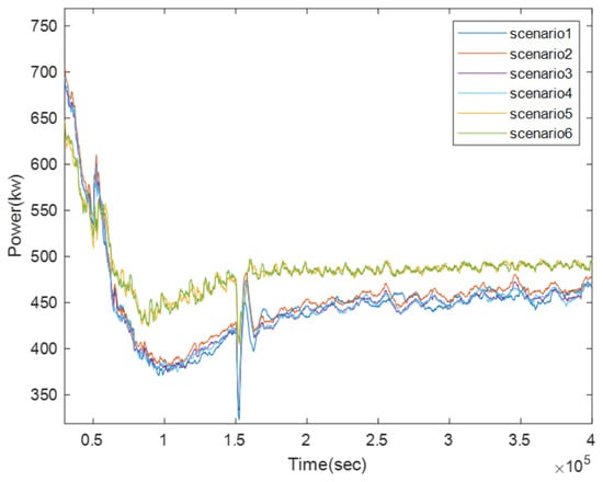
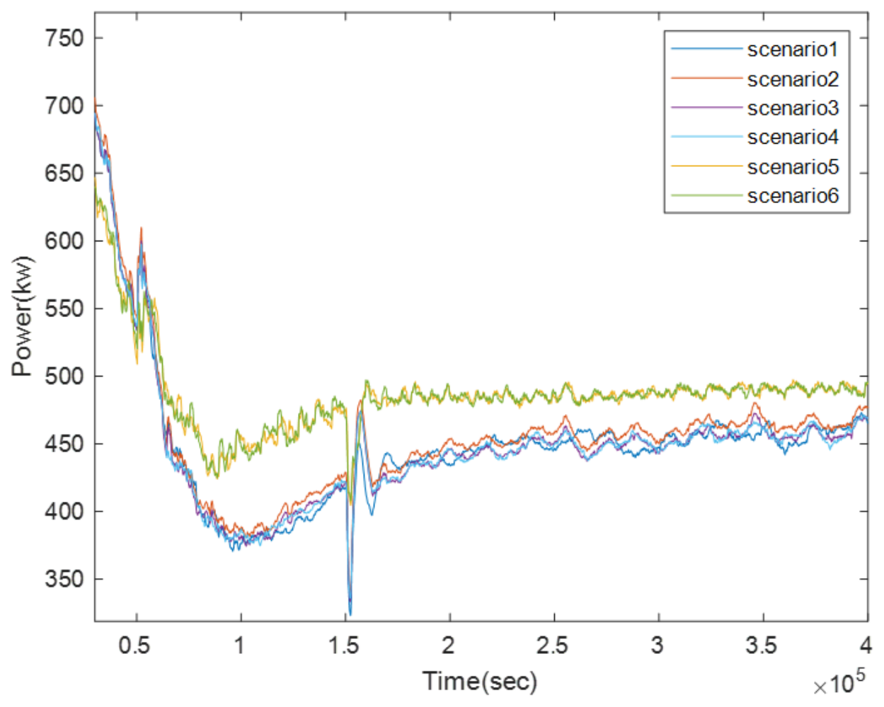
Figure 16 illustrates the output power of the wind power module across different scenarios. It can be observed that, by introducing droop control to enable the wind module’s participation in microgrid frequency regulation, the module can effectively respond to frequency deviation signals via its droop characteristic when the system frequency deviates from the rated value. By releasing reserve power, its output power exhibits a reasonable increase adapted to the frequency regulation requirements. Furthermore, during load switching events, the scenarios incorporating wind power participation in frequency regulation demonstrate a 9.6% reduction in average power fluctuation compared to those without such participation.
Figure 16.
Output of wind power modules in different scenarios.
3.2. Output Characteristics and Parameter Trajectories of the Fuzzy Logic Controller
To comprehensively evaluate the performance and parameter regulation behavior of the designed fuzzy adaptive strategy, this subsection analyzes both the static control surfaces and the dynamic time domain parameter trajectories of the fuzzy logic controller.
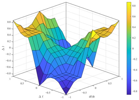
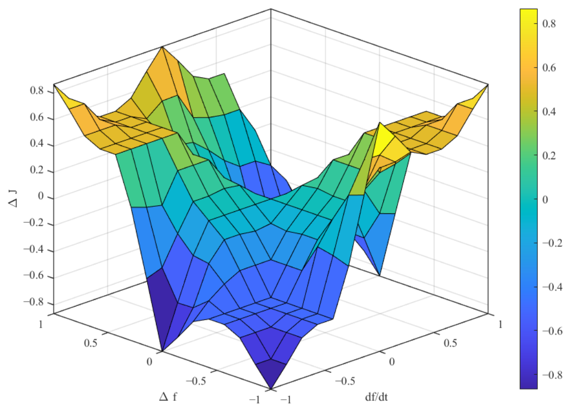
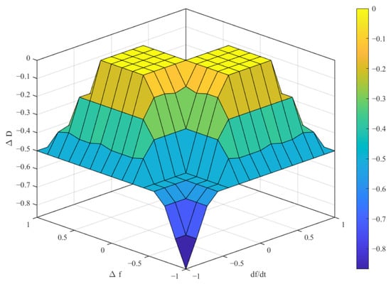
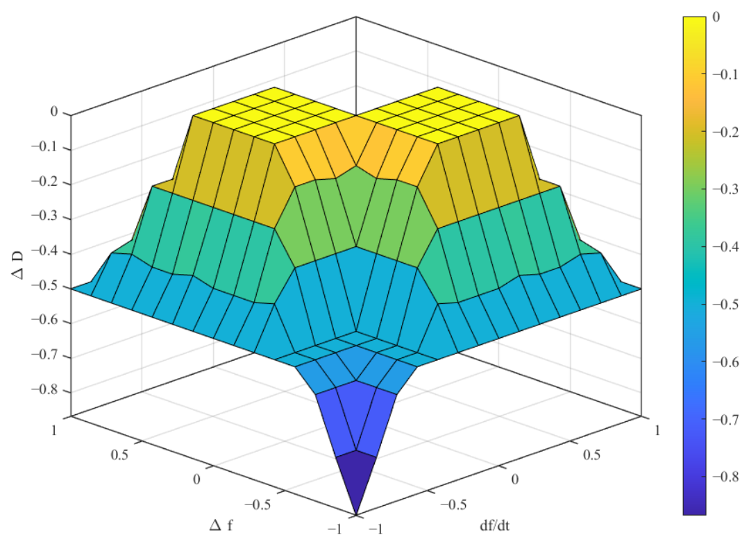
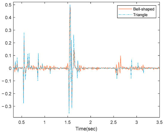
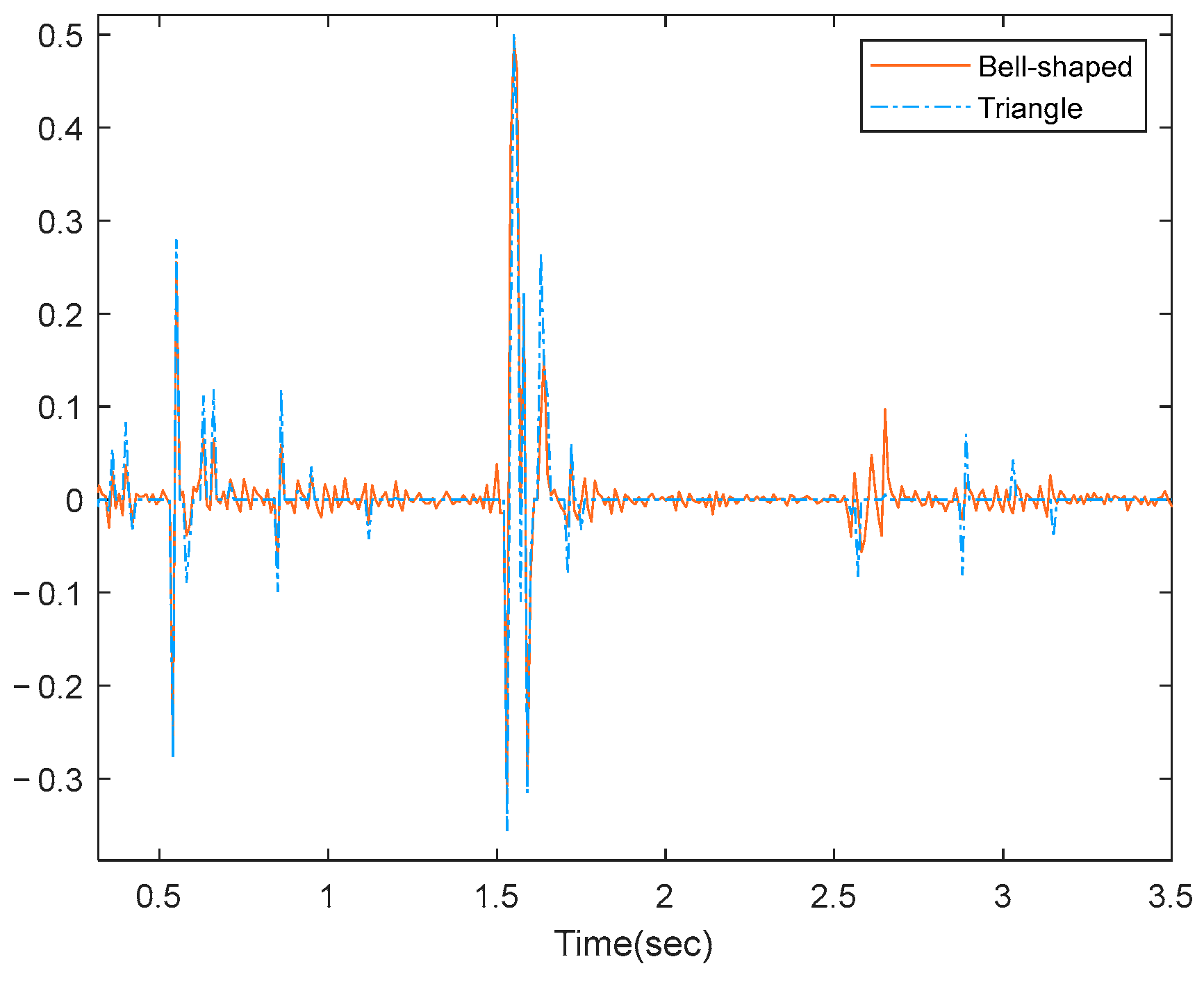
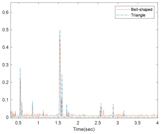
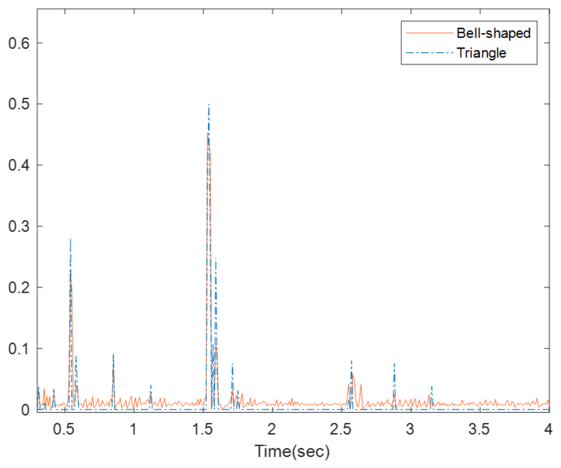
Figure 17 and Figure 18 illustrate the output surface plots for the adaptive inertia J and damping D components of the fuzzy controller, generated based on the fuzzy rules in Table 1 and Table 2. Furthermore, Figure 19 and Figure 20 display the dynamic response curves of J and D in the fuzzy VSG control under bell-shaped and triangular membership functions, respectively.
Figure 17.
Output surface plot of the virtual inertia Delta J fuzzy adaptive component.
Figure 18.
Output surface plot of the damping coefficient Delta D fuzzy adaptive component.
Figure 19.
Variation in virtual inertia J.
Figure 20.
Variation in damping coefficient D.
Analyzing the response characteristics from these figures, it is evident that the fluctuation peaks under triangular membership functions are higher than those under bell-shaped functions. Due to the piecewise linear nature of triangular membership functions, their corresponding curves exhibit “step-like” sharp transitions. In contrast, the continuous and smooth nature of bell-shaped functions results in gentler curve transitions without distinct abrupt slopes.
Consequently, the large-amplitude and sharp fluctuations of J and D under triangular membership functions increase the risk of transient instability in the microgrid. Conversely, the relatively smooth fluctuations under bell-shaped functions achieve a “soft transition” in parameter regulation, thereby enhancing the operational stability of the microgrid during sudden changes in operating conditions.
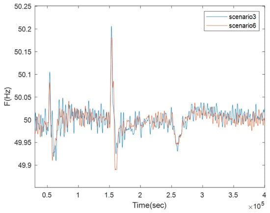
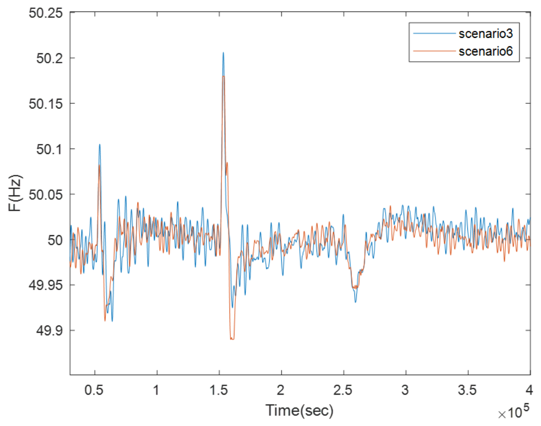
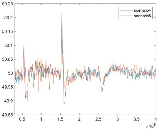
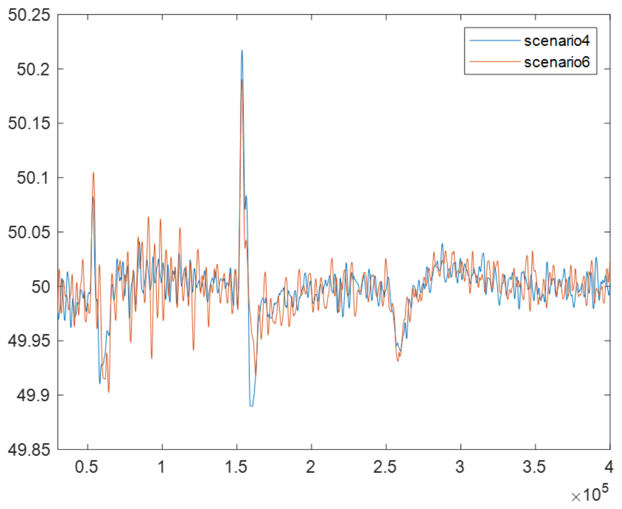
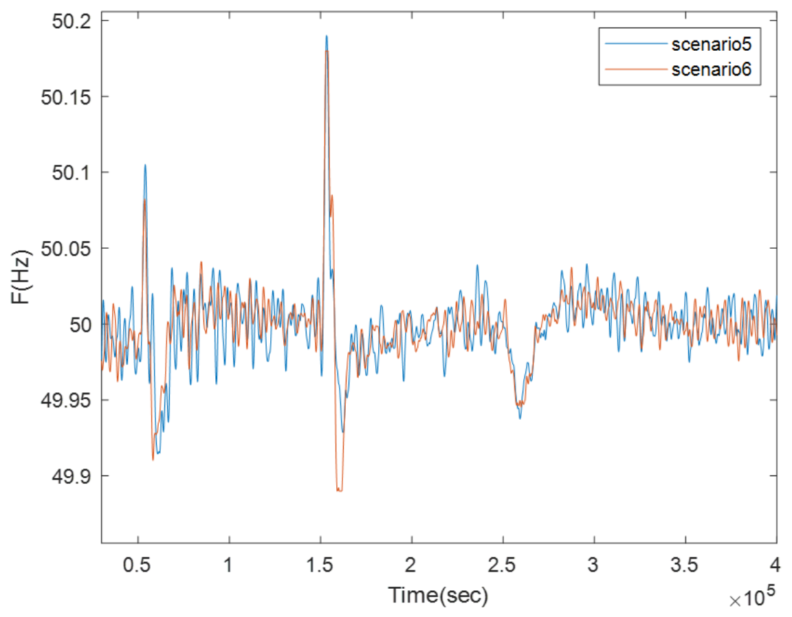
3.3. Analysis of Frequency Regulation Results
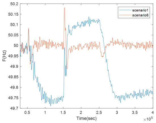
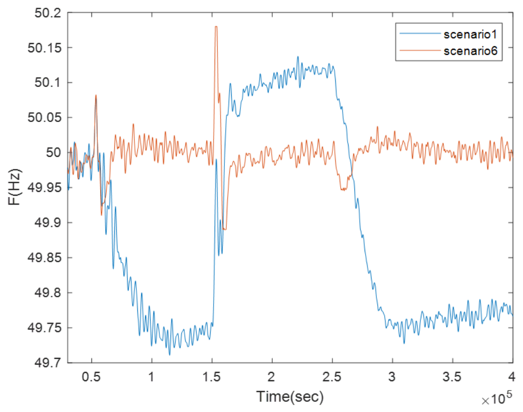
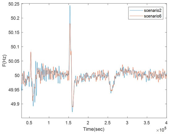
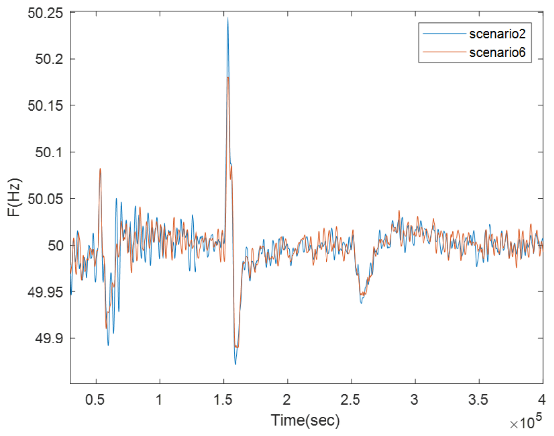
Figure 21, Figure 22, Figure 23, Figure 24 and Figure 25 compare the microgrid frequency responses under the six control scenarios, and the corresponding quantitative indices are summarized in Table 4. Under conventional droop control in Scenario 1, the maximum and mean frequency deviations are 0.289 Hz and 0.165 Hz, respectively. The relatively large mean deviation reflects the steady-state frequency offset associated with the static power frequency droop characteristic. After fixed-parameter VSG control is introduced in Scenario 2, the mean frequency deviation decreases to 0.017 Hz, while the maximum deviation remains 0.245 Hz. This result indicates that the fixed-parameter VSG improves the overall frequency regulation performance but cannot adapt its virtual inertia and damping coefficient to different disturbance stages.
Figure 21.
Frequency fluctuation results.
Figure 22.
Frequency fluctuation results.
Figure 23.
Frequency fluctuation results.
Figure 24.
Frequency fluctuation results.
Figure 25.
Frequency fluctuation results.
Compared with Scenario 2, the triangular fuzzy VSG in Scenario 3 reduces the maximum frequency deviation from 0.245 Hz to 0.206 Hz, corresponding to a reduction of 15.92%. This comparison demonstrates the benefit of online J-D scheduling for transient frequency regulation. Scenario 4 replaces the triangular membership functions with bell-shaped functions. Its mean frequency deviation decreases slightly from 0.019 Hz to 0.017 Hz, whereas the maximum deviation increases from 0.206 Hz to 0.221 Hz. Therefore, changing the membership function shape alone does not improve all frequency indices. The lower mean deviation is consistent with the smoother parameter trajectories shown in the preceding results, while the transient peak response remains dependent on the fuzzy rules and scaling factors.
Wind power frequency support is introduced in Scenarios 5 and 6. Relative to Scenario 3, Scenario 5 reduces the maximum frequency deviation from 0.206 Hz to 0.192 Hz and the mean deviation from 0.019 Hz to 0.017 Hz. Similarly, relative to Scenario 4, the proposed coordinated strategy in Scenario 6 reduces the maximum frequency deviation from 0.221 Hz to 0.181 Hz, corresponding to a reduction of 18.10%, while the mean deviation decreases from 0.017 Hz to 0.016 Hz. These pairwise comparisons isolate the contribution of the supplementary DFIG droop support loop and show that wind power participation improves the frequency response by sharing part of the transient active-power imbalance.
Scenario 6 achieves the smallest maximum and mean frequency deviations among all six cases. Compared with conventional droop control, the proposed method reduces these two indices by 37.37% and 90.30%, respectively. Compared with Scenario 5, which also includes wind power frequency support but uses triangular membership functions, the maximum frequency deviation is further reduced by 5.73%. Overall, the results indicate that adaptive VSG parameter scheduling improves transient regulation relative to fixed-parameter control, while supplementary DFIG droop support provides the main additional improvement in the coordinated wind–storage cases. The detailed results are presented in Table 5.
Table 5.
Comparison of frequency control effects under different scenarios.
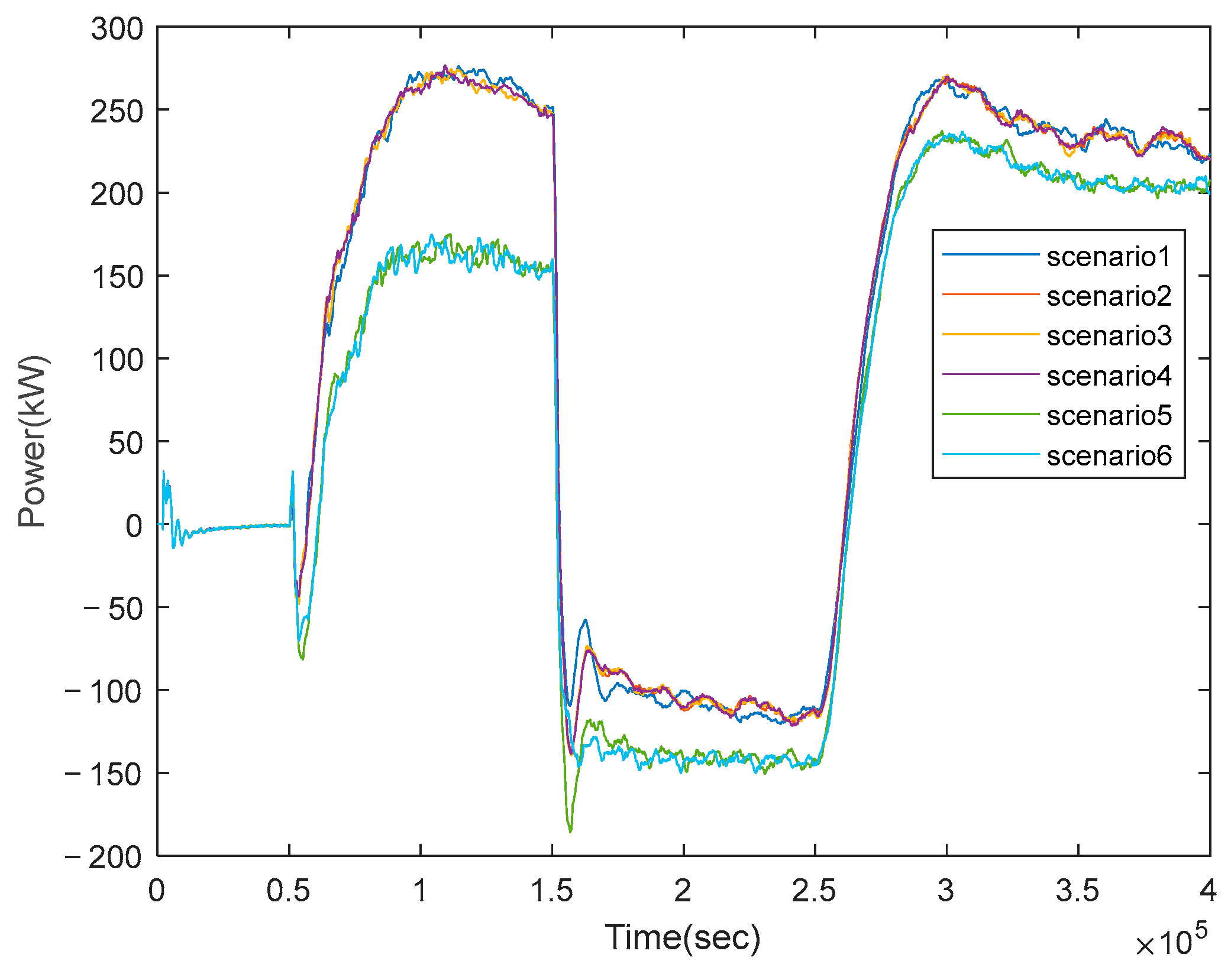
Figure 26 is energy storage output power in different scenarios. Table 6 reports the maximum discharging power, maximum charging power, RMS power, and cumulative energy throughput of the BESS under the six scenarios. The maximum charging power is represented by the absolute value of the minimum BESS power, while the RMS power characterizes the equivalent sustained power loading during the transient process. The cumulative energy throughput is calculated by integrating the absolute value of the BESS power over the simulation interval and is used as a comparative indicator of short-term charging and discharging activity. Because the investigated transient interval is only 4 s, the corresponding BESS SOC variation is small and is therefore not presented separately. The cumulative energy throughput reported in Table 6 is used only as a comparative indicator of the short-term charging and discharging burden, rather than as a direct measure of long-term SOC evolution, battery degradation, or lifetime improvement. In the BESS controller, the d- and q-axis current references generated by the active- and reactive-power PI regulators are independently limited to the range of [−1, 1] p.u. Conditional-integration anti-windup is implemented in both PI regulators, and a rate limiter is additionally applied to the d-axis current reference to avoid abrupt active-current commands.
Figure 26.
Energy storage output power in different scenarios.
Table 6.
Energy storage output power indicators for different scenarios.
In Scenarios 1–4, where the DFIG does not provide supplementary frequency support, the maximum discharging power remains within 274–277 kW, the RMS power is approximately 184–186 kW, and the cumulative energy throughput ranges from 6.757 to 6.946 kWh. The relatively small differences among these cases indicate that changing the ESS-side VSG parameters or membership function shape mainly affects the frequency response characteristics but does not substantially reduce the overall regulation demand imposed on the BESS.
After supplementary DFIG droop support is introduced, the BESS burden indices decrease substantially. In Scenario 6, the maximum discharging power, RMS power, and cumulative energy throughput are 236.853 kW, 155.822 kW, and 5.751 kWh, respectively. Relative to Scenario 1, these indices are reduced by 14.27%, 16.11%, and 17.20%. More importantly, relative to Scenario 4, which employs the same bell-shaped fuzzy VSG but does not include DFIG frequency support, the corresponding reductions are 14.41%, 16.15%, and 14.89%. This pairwise comparison isolates the contribution of the DFIG droop support loop and shows that wind power participation shares part of the transient active-power imbalance, thereby reducing both the instantaneous and cumulative regulation burden imposed on the BESS.
4. Discussion
4.1. Interpretation of Results and Evaluation of the Research Hypothesis
The results provide evidence for answering the research question and evaluating the working hypothesis proposed in the Introduction. Compared with the fixed-parameter VSG in Scenario 2, the adaptive fuzzy VSG cases reduce the maximum frequency deviation and improve the transient response under the investigated disturbances. This improvement is associated with the coordinated online scheduling of the virtual inertia J and damping coefficient D within the admissible region defined by the damping ratio and natural angular frequency constraints. These results support the first part of the hypothesis that constrained J–D scheduling improves the adaptability of the energy storage VSG under varying operating conditions.
The comparisons between Scenarios 3 and 4 and between Scenarios 5 and 6 isolate the influence of the membership function shape because the corresponding cases differ mainly in the use of triangular or bell-shaped membership functions. Together with the parameter trajectory results, these comparisons indicate that the bell-shaped membership functions mainly improve the smoothness of the online parameter commands, although changing the membership function shape alone does not improve every frequency index. In contrast, the comparisons between Scenarios 3 and 5 and between Scenarios 4 and 6 isolate the contribution of supplementary DFIG frequency support. In particular, Scenarios 4 and 6 employ the same bell-shaped fuzzy VSG, while only Scenario 6 includes the DFIG droop support loop. The reductions in frequency deviation, maximum BESS discharge power, RMS power, and cumulative energy throughput therefore show that wind power participation shares part of the transient active-power imbalance and reduces the short-term regulation burden imposed on the BESS. Taken together, these findings support the working hypothesis that constrained adaptive VSG parameter scheduling and supplementary DFIG active-power support can jointly improve microgrid frequency regulation while reducing the BESS regulation burden under the investigated conditions.
4.2. Practical Implications and Limitations
The proposed strategy has practical implementation relevance because the supplementary DFIG droop support term is incorporated into the existing active-power outer loop of the rotor-side converter without changing the basic inner current control structure. In addition, the constructed J-D feasible region provides explicit dynamic-performance bounds for online VSG parameter scheduling. The simulation results indicate that coordinating these two control functions can improve the frequency response while reducing the short-term power and energy burden imposed on the BESS, thereby preserving additional regulation margin for subsequent disturbances.
Nevertheless, several limitations should be acknowledged. The proposed method is evaluated using a nonlinear MATLAB/Simulink model, whereas the theoretical parameter constraints are derived from a reduced-order small-signal model. Therefore, the theoretical analysis characterizes only the local dynamics near the selected operating point and does not constitute a proof of global asymptotic stability under arbitrary large disturbances. In addition, the PV system operates under MPPT control and is treated as an external active-power disturbance rather than an active frequency support unit. Because the simulation interval is only 4 s, the BESS SOC trajectory is not presented separately, and the reported energy throughput is used only as an indicator of short-term regulation burden rather than battery degradation or lifetime improvement. Future work will consider longer operating periods, combined current-vector limits, communication delays, and hardware-in-the-loop validation.
5. Conclusions and Outlook
This paper proposes a wind–storage coordinated frequency control strategy that combines an energy storage fuzzy VSG with supplementary DFIG active-power-frequency droop support. The proposed method is evaluated through six comparative scenarios involving grid-connected/islanded transitions, load switching, and renewable-power variations. The main conclusions are as follows:
- By incorporating the DFIG droop support term into the reduced-order wind–storage model, an admissible J-D scheduling region is established according to prescribed damping ratio and natural angular frequency constraints. This region provides a system-level basis for preventing unsuitable virtual inertia and damping combinations during online parameter adjustment.
- Bell-shaped membership functions provide smoother transitions of the online J and D commands than triangular membership functions under the same fuzzy rules and scaling factors. However, changing the membership function shape alone does not improve every frequency response index.
- The coordinated case combining the bell-shaped fuzzy VSG and supplementary DFIG droop support achieves the best overall performance among the six scenarios. Its maximum and mean frequency deviations are 0.181 Hz and 0.016 Hz, respectively. Relative to the corresponding bell-shaped fuzzy VSG case without DFIG support, the maximum BESS discharging power, RMS power, and cumulative energy throughput are reduced by 14.41%, 16.15%, and 14.89%, respectively. These results indicate that the DFIG shares part of the transient active-power imbalance and reduces the short-term regulation burden imposed on the BESS.
Overall, the simulation results support the working hypothesis that constrained adaptive VSG scheduling and supplementary DFIG active-power support can jointly improve microgrid frequency regulation while reducing the BESS regulation burden under the investigated conditions.
Author Contributions
Conceptualization, J.Z. and J.F.; methodology, X.Z. and J.Y.; software, J.Z., J.F., D.T. and H.W.; validation, X.Z. and D.T.; formal analysis, X.Z., J.Z., J.F. and J.Y.; investigation, X.Z. and J.Y.; resources, J.Z. and J.F.; data curation, J.Z., D.T. and Z.F.; writing—original draft preparation, D.T., H.W. and Z.F.; writing—review and editing, X.Z., J.Z., D.T. and H.W.; visualization, J.Y.; supervision, X.Z., J.Z., J.F. and J.Y.; project administration, J.Z., J.F., D.T. and Z.F.; funding acquisition, X.Z., J.Z., J.F. and J.Y. All authors have read and agreed to the published version of the manuscript.
Funding
This research was funded by the Science and Technology Project of State Grid Jiangsu Electric Power Co., Ltd. Electric Power Research Institute (J2025086).
Data Availability Statement
The original contributions presented in this study are included in the article. Further inquiries can be directed to the corresponding author.
Conflicts of Interest
Authors Xian Zhen, Jianhua Zhou, Juntao Fei, and Jianyu Yu were employed by the Research Institute of State Grid Jiangsu Electric Power Co., Ltd. The remaining authors (Dingxin Tang, Haixin Wu, and Zhixin Fu) declare that the research was conducted in the absence of any commercial or financial relationships that could be construed as a potential conflict of interest. The authors declare that this study received funding from the Electric Power Research Institute of State Grid Jiangsu Electric Power Co., Ltd. (Project No. J2025086). The funder was not involved in the study design, data collection, analysis, interpretation of data, the writing of this article, or the decision to submit it for publication.
Abbreviations
The following abbreviations are used in this manuscript:
| VSG | Virtual Synchronous Generator |
| DFIG | Doubly Fed Induction Generator |
| PV | Photovoltaic |
| ESS | Energy Storage System |
| PCC | Point of Common Coupling |
| MPPT | Maximum Power Point Tracking |
| RSC | Rotor-Side Converter |
| GSC | Grid-Side Converter |
References
- Zou, Z.; Tang, J.; Buticchi, G.; Liserre, M. Stabilization of distribution grids with high penetration of renewables: The path from decentralized control to a centralized one. IEEE Ind. Electron. Mag. 2023, 17, 17–31. [Google Scholar] [CrossRef]
- Farrokhabadi, M.; Cañizares, C.A.; Simpson-Porco, J.W.; Nasr, E.; Fan, L.; Mendoza-Araya, P.A.; Tonkoski, R.; Tamrakar, U.; Hatziargyriou, N.D.; Lagos, D.; et al. Microgrid Stability Definitions, Analysis, and Examples. IEEE Trans. Power Syst. 2020, 35, 13–29. [Google Scholar] [CrossRef]
- Shadoul, M.; Ahshan, R.; AlAbri, R.S.; Al-Badi, A.; Albadi, M.; Jamil, M. A Comprehensive Review on a Virtual Synchronous Generator: Topologies, Control Orders and Techniques, Energy Storages, and Applications. Energies 2022, 15, 8406. [Google Scholar] [CrossRef]
- Bevrani, H.; Golpîra, H.; Messina, A.R.; Hatziargyriou, N.; Milano, F.; Ise, T. Power system frequency control: An updated review of current solutions and new challenges. Electr. Power Syst. Res. 2021, 194, 107114. [Google Scholar] [CrossRef]
- Zhong, Q.C.; Weiss, G. Synchronverters: Inverters That Mimic Synchronous Generators. IEEE Trans. Ind. Electron. 2011, 58, 1259–1267. [Google Scholar] [CrossRef]
- Sahoo, S.K.; Sinha, A.K.; Kishore, N.K. Control techniques in AC, DC, and hybrid AC–DC microgrid: A review. IEEE J. Emerg. Sel. Top. Power Electron. 2018, 6, 738–759. [Google Scholar] [CrossRef]
- Abid, M.S.; Ahshan, R.; Abri, R.A.; Al-Badi, A.; Albadi, M. Techno-economic and environmental assessment of renewable energy sources, virtual synchronous generators, and electric vehicle charging stations in microgrids. Appl. Energy 2024, 353, 122028. [Google Scholar] [CrossRef]
- Wang, F.; Zhang, L.; Feng, X.; Guo, H. An adaptive control strategy for virtual synchronous generator. IEEE Trans. Ind. Appl. 2018, 54, 5124–5133. [Google Scholar] [CrossRef]
- Ren, M.; Li, T.; Shi, K.; Xu, P.; Sun, Y. Coordinated control strategy of virtual synchronous generator based on adaptive moment of inertia and virtual impedance. IEEE J. Emerg. Sel. Top. Circ. Syst. 2021, 11, 99–110. [Google Scholar] [CrossRef]
- Xu, D.; Tang, L.; Jiang, B.; Pan, T.; Liu, J.; Hua, W. Cooperative adaptive command-filtered backstepping control for EVs to UPS-microgrid via virtual synchronous generator. IEEE Trans. Cybern. 2024, 54, 5369–5380. [Google Scholar] [CrossRef] [PubMed]
- Gurski, E.; Kuiava, R.; Perez, F.; Benedito, R.A.S.; Damm, G. A Novel VSG with Adaptive Virtual Inertia and Adaptive Damping Coefficient to Improve Transient Frequency Response of Microgrids. Energies 2024, 17, 4370. [Google Scholar] [CrossRef]
- Shi, T.; Sun, J.; Han, X.; Tang, C. Research on adaptive optimal control strategy of virtual synchronous generator inertia and damping parameters. IET Power Electron. 2024, 17, 121–133. [Google Scholar] [CrossRef]
- Koiwa, K.; Tomabechi, A.; Zanma, T.; Liu, K.Z. Dynamic optimisation of virtual synchronous generator to enhance stability of power system. IET Smart Grid 2024, 7, 858–871. [Google Scholar] [CrossRef]
- Zhang, W.; Wang, B.; Guo, J.; Zhang, Y.; Wang, S.; Wu, Y. Power Stability Control of Wind-PV-Battery AC Microgrid Based on Two-Parameter Fuzzy VSG. Front. Energy Res. 2023, 11, 1298033. [Google Scholar] [CrossRef]
- Lyu, L.; Wang, X.; Zhang, L.; Koh, L.H. Fuzzy control based virtual synchronous generator for self-adaptive control in hybrid microgrid. Energy Rep. 2022, 8, 12092–12104. [Google Scholar] [CrossRef]
- Zhao, H.; Chen, X.; Wang, C.; Liu, X.; Qiu, J. SOC Balanced Power Distribution Control Strategy of a DC–DC Converter with Virtual Synchronous Generator. Electronics 2022, 11, 3978. [Google Scholar] [CrossRef]
- Teng, Q.; Xu, D.; Yang, W.; Li, J.; Shi, P. Neural network-based integral sliding mode backstepping control for virtual synchronous generators. Energy Rep. 2021, 7, 1–9. [Google Scholar] [CrossRef]
- Kang, H.; Sun, Y.; Liu, J.; Chen, Z.; Shi, X.; Zhang, X.; Shi, Y.; Yang, P. Research on the Primary Frequency Regulation Strategy of Wind-Storage Collaborative Participation Systems Considering the State of Charge of Energy Storage. Energies 2024, 17, 6333. [Google Scholar] [CrossRef]
- Tu, S.; Zhang, B.; Jin, X. Research on DFIG-ES system to enhance the fast-frequency response capability of wind farms. Energies 2019, 12, 3581. [Google Scholar] [CrossRef]
- Miao, L.; Wen, J.; Xie, H.; Yue, C.; Lee, W.J. Coordinated Control Strategy of Wind Turbine Generator and Energy Storage Equipment for Frequency Support. IEEE Trans. Ind. Appl. 2015, 51, 2732–2742. [Google Scholar] [CrossRef]
- Zhang, S.; Mishra, Y.; Shahidehpour, M. Fuzzy-Logic Based Frequency Controller for Wind Farms Augmented with Energy Storage Systems. IEEE Trans. Power Syst. 2016, 31, 1595–1603. [Google Scholar] [CrossRef]
- Wu, Z.; Gao, D.W.; Zhang, H.; Yan, S.; Wang, X. Coordinated Control Strategy of Battery Energy Storage System and PMSG-WTG to Enhance System Frequency Regulation Capability. IEEE Trans. Sustain. Energy 2017, 8, 1330–1343. [Google Scholar] [CrossRef]
- Lin, C.-H.; Wu, Y.-K. Coordinated Frequency Control Strategy for VSC-HVDC-Connected Wind Farm and Battery Energy Storage System. IEEE Trans. Ind. Appl. 2023, 59, 5314–5328. [Google Scholar] [CrossRef]
- Shu, H.; Dong, H.; Wang, G.; Chen, J.; Shi, B.; Tang, Y. Wind-storage coordinated control strategy for inertia enhancement of high ratio renewable energy power systems. J. Energy Storage 2024, 97, 112998. [Google Scholar] [CrossRef]
- Pei, M.; Wang, Q.; Ye, L.; Luo, Y.; Sha, L.; Zhang, Z.; Song, X. Hierarchical control strategy of wind-storage frequency support for SOC recovery optimization and arbitrage revenue. Appl. Energy 2024, 365, 123229. [Google Scholar] [CrossRef]
- Shu, H.; Wang, G.; Chen, J.; Ma, H.; He, T. Coordinated control of wind-storage combined with primary frequency regulation and variable coefficient based on wind speed and SOC. J. Energy Storage 2024, 87, 111356. [Google Scholar] [CrossRef]
- Yang, D.; Jin, Z.; Zheng, T.; Jin, E. An adaptive droop control strategy with smooth rotor speed recovery capability for type III wind turbine generators. Int. J. Electr. Power Energy Syst. 2022, 135, 107532. [Google Scholar] [CrossRef]

Disclaimer/Publisher’s Note: The statements, opinions and data contained in all publications are solely those of the individual author(s) and contributor(s) and not of MDPI and/or the editor(s). MDPI and/or the editor(s) disclaim responsibility for any injury to people or property resulting from any ideas, methods, instructions or products referred to in the content. |
© 2026 by the authors. Licensee MDPI, Basel, Switzerland. This article is an open access article distributed under the terms and conditions of the Creative Commons Attribution (CC BY) license.