


Abstract
The development of ferrous metallurgy, as with most industrial sectors, is progressing toward the adoption of IIoT technologies and the development of digital automatic control systems for electrotechnical and mechatronic complexes. This direction is implemented within the paradigm of digital twins (DTs), which enable the use of advanced design methods, virtual commissioning, and maintenance. The concept of relatively simple object-oriented DTs created using available software and applicable at individual stages of the equipment lifecycle has been substantiated. The relationship between the object-oriented approach and M. Grieves’ classification system has been determined. The contribution of this paper lies in the fact that this problem is addressed for the first time using the example of electrotechnical systems of rolling mills. Definitions of DTs are provided, along with a brief overview of digital platforms developed by leading manufacturers of metallurgical equipment. The development of object-oriented DTs based on Simulink Real-Time modules and domains of the Simscape library is substantiated. A methodology for their virtual tuning using Hardware-in-the-Loop (HIL) simulation is proposed. The results of developing an aggregated DT of interconnected electric drives of the upper and lower rolls (UMD and LMD) of the horizontal stand of the 5000 plate rolling mill are presented. An example of DT implementation in a programmable logic controller (PLC) based on a multicore processor using CODESYS 3.5 software is provided. The advantages and prospects of this approach are discussed. Validation of the results is performed by comparing processes during virtual tuning with oscillograms obtained from the actual mill. Satisfactory accuracy is confirmed, and recommendations for the broader application of the developed object-oriented digital twins are given.
Keywords:
digital twin; concept; rolling mill; electric drive; Simulink Real-Time; Simscape; CODESYS 3.5 1. Introduction
At present, all major metallurgical enterprises declare their commitment to a “digital” development trajectory. Digitalization—defined as a deep transformation of production through the use of digital technologies—enables companies to reduce operational risks, respond more rapidly to changes, and improve efficiency through virtual execution of operations. According to experts from leading companies Nippon Steel and Sumitomo Metal Corporation (Japan), the foundation of any “smart” metallurgical plant lies in bottom-up innovation. At such enterprises, numerous electronic systems for control, measurement, and monitoring are integrated into a unified network, allowing the use of a wide range of process and equipment condition parameters. This increases productivity, ensures high product quality, and facilitates maintenance planning and equipment replacement. In addition, the adoption of new technologies improves safety in steelmaking operations.
The driving force behind the intelligent manufacturing paradigm is the digital twin. References [1,2,3] examine the role of DTs in implementing the concept of “digital metallurgy.” Use cases of digital twins across the industrial enterprise lifecycle, substantiated by Siemens, are presented in [4]. Reviews in [5,6,7] provide an overview of DT applications in industry. A significant body of research focuses on the development of DTs for the metallurgical sector. In particular, refs. [8,9,10] analyze their role in the implementation of “digital” or intelligent metallurgical plants. According to this concept, “an intelligent steel plant optimizes its production processes–from raw materials to final products–in an adaptively automated manner.” It is evident that the use of digital twins is especially promising in the development and improvement of rolling mills, which represent some of the most complex units in metallurgical production. Particular attention is given to the creation of DTs for technological lines and their application in solving production management challenges.
Despite extensive research on DTs and their applications, most existing approaches are tailored to specific objects. Thus, the core idea of applying DTs in industry is the dynamic virtual software representation of corresponding physical assets and processes. “In this context, speaking of a digital twin means referring to a digital replica of a machine (or its individual component), a production line, or even an entire plant during its evolution or state change” [11]. As an example, Figure 1 illustrates the structure of a digital twin of an automated electric drive. Its main elements are the physical object (the electric drive itself) and the digital object (the virtual model). A bidirectional exchange of information occurs between them, which distinguishes a DT from a digital model and a digital shadow. However, as shown in [12,13], in certain cases—particularly during development and commissioning stages—the presence of a physical object is not mandatory. In such scenarios, the physical object is replaced by a model implemented in a separate programmable logic controller (PLC) or on a dedicated core of a multicore processor. This approach simplifies the setup of electrotechnical systems and eliminates the risk of abnormal situations during commissioning procedures.
Figure 1.
Structure of a digital twin of an automated electric drive.
1.1. Definition of the Digital Twin
Experts note that “defining what a digital twin is represents a complex task” [14]. The fact that dozens of definitions of DTs can be found in the literature clearly illustrates this issue. The origin of the term is attributed to Michael Grieves, who introduced the concept of the digital twin in 2003 during a lecture on product lifecycle management [2]. The initial description defined a digital twin as “a virtual representation of a physical product containing information about that product, originating from the field of lifecycle management.” Such a definition is inherently complex and has evolved over time.
For some authors, a DT is “a simulation model that reflects physical systems and enables their modeling,” while for others it is “a representation capable of reflecting the state of a real asset, allowing it to be monitored, controlled, and modified” [15]. The authors of [16] presented a review of DT definitions available in the literature for the period 2012–2024. Definitions of the most common concepts are provided in [17,18,19,20]. In particular, DTs are described as “a functional system for continuous process optimization formed through the interaction of physical and digital production lines” [17], as “a modeling approach with real-time control and optimization capabilities for products and production lines” [18], and as “a method or tool used for simulating and modeling the behavior and state of objects” [19], among others. The authors of [20] developed a DT concept that incorporates interaction between personnel and coordination of tasks within the production system. In this and several other studies, the human factor—along with its knowledge and expertise—is considered a structural component of the DT.
For industrial applications, the definition provided in [21,22] is particularly relevant: “A digital twin represents a virtual replica of its physical asset, created from structural and behavioral models, primarily for baseline control, monitoring, and performance evaluation.” This definition is clarified by the structure shown in Figure 2 [23]. The definition adopted in this paper corresponds to this architecture. For industrial enterprises, a simplified formulation is acceptable: “Digital twins are replicas of physical production assets that provide means for monitoring and controlling them” [24]. In the development of the concept of object-oriented DTs, this study adopts the definition given in GOST R 57700.37–2021, according to which “a digital twin is a system consisting of a digital model of a product and bidirectional information links with the product (if present) and/or its components” [1]. In other words, a DT is considered to consist of a physical object and its virtual counterpart, provided that data exchange occurs between them [25]. This approach is explained by the fact that digital twins of industrial units must be related to the object under study, which may be a rolling mill stand, an electromechanical system, a hydraulic device, etc. The above-mentioned definition [1] corresponds to this approach. It is certainly not the only definition that can be used to represent the essence of the object-oriented approach to creating DTs; however, it correctly reflects the essence of the information link between an object and its virtual model.
Figure 2.
Architecture of a digital twin.
In support of the above, it should be acknowledged that the statement that there is currently no unified model for developing a Digital Twin in general form is valid [26]. To solve this problem, the following is proposed: “the object-oriented concept is a paradigm for developing DT models based on the concept of ‘objects,’ which includes behavior, state, and identity.” It has such properties as abstraction, encapsulation, inheritance, and polymorphism [27]. These features can be effectively used to represent real-world entities, which is useful in DT modeling [28]. In [28], the object-oriented concept is used to develop an adaptable DT model for various physical elements in the workshop of an industrial enterprise. An adaptable Digital Twin model based on the object-oriented concept is proposed in [26]. The advantages of this approach are confirmed in articles on the digitalization of power systems [29,30].
The named paradigm concerns the development of mathematical models, which is not new. The fundamental difference of the proposed concept of object-oriented DTs is its application not only to programming tasks, but also to the creation of a DT as a hardware–software complex reflecting the essence of an industrial object at individual stages of its lifecycle. This constitutes one of the limitations of an object-oriented DT and, at the same time, one of its advantages. When such a complex is created, various options for placing virtual models are implemented, for example, on a separate computing device, in the PLC that controls the object, or in a PLC based on a multicore processor (see Section 5.3). Delays in information exchange between the hardware and virtual parts are also assessed, and a number of additional tasks are solved. At the same time, the created DT must provide all the properties of the above-mentioned concept: encapsulation, inheritance, and polymorphism. From this reasoning it follows that the proposed concept does not refer to a new category of digital twins, but is instead a methodology for their development. This issue requires more in-depth study. In the present article, the above-mentioned approach is implemented using the example of digital twins of electrotechnical systems of rolling mills.
1.2. Digital Twins of Rolling Mills
At present, DTs are increasingly considered a means of improving the performance of industrial units through the use of computational methods enabled by their virtual counterparts. The importance of digital twins is recognized both in academic research and in industry. At the same time, a growing number of developers adhere to the view that “obtaining a single digital twin representing the entire system and using it as the sole source of truth is illusory” [31]. This is explained by the fact that “using the same model for simulations throughout the entire development process, from design to validation, is an ideal goal that is difficult to achieve in practice.” It is even less feasible to develop a DT capable of representing an object at all stages of its lifecycle, from design to decommissioning. In this context, there arises a need to develop relatively simple DTs designed for specific objects, taking into account their particular features and ensuring maximum accuracy at individual stages of the lifecycle. These DTs should be accessible for both research purposes and industrial application. In this paper, they are referred to as “object-oriented digital twins,” and their development and application concept is substantiated for the first time using the example of electrotechnical systems of a rolling mill. They can be most effectively applied at the following stages of the lifecycle of electrotechnical systems [32]:
- At the modeling stage during the development and design of equipment and automation systems;
- At the commissioning stage through the creation of virtual models of the object;
- During operation for system retuning and condition monitoring;
- Within monitoring systems for real-time condition assessment.
Accordingly, the study of various aspects of system or device behavior may require different modeling tools and models with varying levels of detail. Practical experience indicates that relatively simple DTs, intended for use at the most critical stages of the lifecycle, are sufficient for applied purposes. In this regard, the task is formulated to develop such DTs for the stages of virtual commissioning, setup, and tuning of electrotechnical systems. These stages are relevant both during initial commissioning and equipment modernization, as well as for monitoring technical condition during standard operation.
Conceptual directions for the development of DTs for rolling units have been substantiated by specialists from Primetals Technologies (a joint venture of Mitsubishi Heavy Industries and partners) [33]. It is argued that “with the development of plant digitalization, a revolution has occurred in rolling production.” A leading manufacturer of rolling equipment, SMS group, has developed strategies for advancing digitalization in the steel industry [34]. According to SMS group and SMS digital, the main functions of DTs include monitoring, modeling, optimization, prediction, and training [35]. In this work, virtual commissioning is selected as an independent direction, based on the tuning of industrial systems using dedicated digital models, although it is not explicitly emphasized by the aforementioned companies. In this regard, the application of the DT concept to commissioning and virtual commissioning of electrotechnical systems is substantiated. A new function is proposed—virtual tuning of controllers of automated electric drives using Hardware-in-the-Loop (HIL) simulation. HIL is a type of real-time simulation used for testing control algorithms [36]. Its implementation typically involves a real-time computer for executing the model and a programmable logic controller (PLC). The QNX operating system is often used for process control tasks.
According to [37], HIL simulation is increasingly applied to evaluate the performance of electric drives. Three types of HIL simulation are distinguished: signal-level, power-level, and mechanical-level. Considerable attention is also given to the use of HIL in the development and virtual tuning of power converters. As emphasized in [38], “accurate models of power electronic converters can significantly improve the precision of HIL simulators.” Publication [39] addresses the development and implementation of a low-cost real-time control platform for power electronics applications, while [40] presents detailed real-time modeling of power converters and electrical machines.
At the same time, information on the use of HIL simulators for the modernization and reconstruction of operating industrial units remains limited. This underscores the relevance of presenting practical results demonstrating the application of HIL in industrial environments. The following Section 3 and Section 4 provide such results, focusing on the use of HIL for the virtual commissioning of electrotechnical systems of a rolling mill stand.
1.3. Virtual Commissioning
The advantages and challenges of using DTs for virtual commissioning (VC) of industrial assets are considered in [41,42,43]. It is noted in [44] that the use of a digital twin makes it possible to reduce commissioning time by 40%. The authors of [45] state that “virtual models developed for VC help system developers not only at the stage of physical construction, but also at subsequent stages of the lifecycle by providing a common virtual model and a digital twin of production processes and the product.” The capabilities and advantages of this approach are considered below.
Since digital twins are accurate representations of physical assets, they can be used to optimize the VC stage. Instead of commissioning a new electrotechnical system as a physical object, virtual commissioning is used. It includes creating a digital twin followed by testing and verification in a simulated virtual environment. This provides the following capabilities:
- –
- Testing and debugging algorithms in a virtual environment;
- –
- Virtual investigation of equipment operation, identification of possible problems, and rapid assessment of alternative solutions;
- –
- Rapid modification of operating procedures and control algorithms;
- –
- Training of operators and personnel under protected conditions, which is important for electrical installations in metallurgical production;
- –
- Simulation of the impact of new equipment on existing equipment in order to identify bottlenecks and eliminate them before installation.
As a result, instead of physical commissioning of the object, virtual commissioning provides for the creation of a digital twin followed by testing and verification of the model in a simulated virtual environment. This approach, in combination with the object-oriented approach, provides the following advantages:
- Reduced development time. Modular design and reusable components can significantly shorten development cycles.
- Improved maintainability. Owing to the principle of encapsulation, changes or updates to individual components can be made without affecting the entire system.
- Improved performance. Accurate models and simulations can lead to improved control strategies and higher system performance.
- Cost savings through process optimization and reduced downtime.
The listed advantages have been confirmed in the course of development and industrial implementation of digital twins and VC technologies based on available software [46,47].
Given these capabilities, the need for strict synthesis of controllers using complex mathematical methods becomes less critical. The following methodology for virtual tuning is proposed:
- Preliminary coarse justification of the control system structure and the controller transfer function;
- Tuning using HIL.
This approach is applied at a number of metallurgical plants during commissioning and modernization of rolling mills. It is reported to provide the following advantages [32]:
- Enabling commissioning activities even at the design stage (more commonly at the stage of virtual commissioning);
- Reduces execution time by 35–40% [48,49]; in [50], it is stated that in the automation industry this figure is up to 50%;
- Reducing commissioning workload by up to 40%.
2. Problem Formulation
2.1. Characteristics of Digital Platforms for the Development of Industrial DTs
Despite the relevance of addressing these issues, a number of studies rightly point out that, in industry, theoretical research and development of DTs significantly outpace their practical implementation. An analysis of the situation at metallurgical plants confirms that the level of practical application of digital technologies on operating units remains low. As noted in [51], “information on the use of DTs across the lifecycle stages of industrial equipment is limited. The willingness of industrial stakeholders to adopt them is constrained by the lack of a clear methodology for DT development tailored to practical tasks.” According to the authors, the disadvantages of digital products offered by well-known manufacturers of rolling equipment lie in their complexity and narrow specialization. Digital twins are typically developed on the basis of specialized digital platforms, primarily intended for the design and construction of new units. As a result, they have not found widespread practical application on existing equipment at metallurgical plants.
In support of this statement, Table 1 provides a brief overview of software tools and platforms used for the development of DTs by leading industrial equipment manufacturers. The information is drawn from corporate publications [43,52] and other available sources.
Table 1.
Digital platforms of leading companies.
As follows from the table, despite the wide range of directions, information on the application of digital platforms for creating DTs of metallurgical plant units remains limited, although leading companies are conducting individual developments of DTs for rolling mills. In particular, Conwertim (part of GE Energy) has developed the “Technological Regulation System—TER,” which incorporates all functions directly affecting the product quality of cold rolling mills. As noted above, the leading manufacturer of rolling equipment, SMS group, has developed strategies for advancing digitalization in the steel industry. These strategies are based on the Plug&Work approach, which enables functional testing of control systems at the facility prior to commissioning [53]. This concept has been implemented in the development of digital twins for aluminum rolling mills. Its limitations include narrow specialization and, consequently, restricted applicability. In addition, its use requires significant computational resources, which further constrains its deployment on operating units.
The conducted review suggests that information on digital twins developed on the basis of well-known digital platforms and suitable for large-scale implementation in rolling mills is practically absent. In this regard, the development of a DT concept based on software widely used in industrial enterprises and research organizations appears justified. Such tools include MATLAB and its applications Simulink Real-Time, Simscape, among others, which are well established and successfully applied in control system development [54,55,56]. Among these, Simscape appears particularly promising. It is a family of software tools developed by MathWorks for physical and simulation modeling, enabling the description and analysis of real systems through interconnected blocks rather than solely through mathematical equations. Unlike Simulink, which focuses on abstract signal modeling, Simscape is designed to model physical objects and components such as motors, pumps, electrical circuits, and mechanical systems. Additional Simscape products provide more advanced components, including control systems and analytical tools. The Simscape language, based on MATLAB, enables the creation of textual components, domains, and libraries for physical modeling [57], which constitutes a significant advantage when selecting tools for implementing digital twin concepts.
These applications should be used for developing digital models and control algorithms for electro- and hydraulic drive systems of rolling units. They are accessible (subject to licensing) and do not require extensive user training. In addition, DT implementations based on the Astra.IDE language have been examined, enabling development within editors compliant with the IEC 61131-3 PLC standard, as well as within the CODESYS 3.5 environment, which is used for programmable logic controllers equipped with multicore processors.
It is known that the structural approach is predominantly used in the development of electrotechnical and mechatronic systems of industrial units. According to the definition, this is a method of analysis that considers an object as a system of interrelated elements combined by a certain structure. It involves studying the object, identifying its constituent parts and the links between them, and analyzing the functions of these elements within a single whole. It is noted in [58] that the main advantages of this approach include ease of debugging and testing, as well as a reduced probability of errors. Its disadvantages are the complexity of implementing logical structures and difficulties in making changes to an already existing structure. These disadvantages certainly manifest themselves in the development of electrotechnical complexes of rolling mills. The desire to eliminate the above-mentioned shortcomings led to the development of new ideas based on object decomposition [59]. As noted above, this principle of developing hardware–software systems has been termed the object-oriented approach.
2.2. Object-Oriented Approach to the Development of Digital Twins
Although the object-oriented approach is well known and widely used in programming, its application as a conceptual basis for digital twin development is proposed here for the first time. Unlike the system-oriented approach, it is not yet widely established in this context, which necessitates a clear definition and justification of its applicability to DT development. The key advantage of this approach lies in its modular architecture, which simplifies modeling and improves the management of complex systems. To implement it effectively, it is necessary to establish a classification of DTs by levels of complexity and functional purpose.
In [32], a concept for developing relatively simple object-oriented digital twins is proposed. These DTs are intended to be created without the use of specialized digital platforms, instead relying on software commonly employed in industrial enterprises and research institutions. The concept is based on the well-known classification of DTs into categories defined by Michael Grieves and presented in Table 2 [60]. The abbreviations given in the table are used subsequently throughout the discussion.
Table 2.
Categories of digital twins defined by M. Grieves.
The distinguishing features of object-oriented digital twins are as follows:
- Orientation toward a specific object (for rolling mills, this may include the electromechanical system of a stand or coiler, an individual motor, or a power converter).
- Development based on accessible software without the use of specialized digital platforms.
- Application not across the entire lifecycle, but only at specific stages for which the given DT is created.
This determines the following advantages of the object-oriented approach in DT development (which also represent its key features) [26]:
- Modular architecture—individual components (motors, mechanical transmissions, hydraulic devices, etc.) are considered as independent objects, which simplifies design, modification, and reuse of system elements.
- Encapsulation (restricted access)—this is the process of separating the elements of an object that define its structure and behavior. Its purpose is that “no part of a complex system should depend on the internal structure of another part. Each object encapsulates its own data (e.g., motor speed, torque) and methods (speed control, torque calculation), ensuring data integrity and reducing unintended side effects.”
Encapsulation provides only an interface for interaction with the object. This principle is widely used by manufacturers of electrical and electronic equipment. As a rule, control algorithms and software code have restricted user access (or are completely inaccessible). This limits personnel intervention in system configuration, ensuring reliable operation, although it often leads to criticism from operators.
- 3.
- Inheritance and polymorphism. Complex systems can be created by inheriting properties of base classes (e.g., electric machine classes) and defining specialized behavior for different types (synchronous, asynchronous drives, etc.).
- 4.
- Modeling and analysis. Object-oriented models can be effectively created using tools such as Simulink, enabling analysis of system processes under various conditions.
The object-oriented approach is of significant importance for the development of digital twins of electrotechnical complexes of rolling mills, ensuring virtual commissioning, performance optimization, and predictive maintenance. It enables modular design, simplifies modeling, and improves the management of complex interconnected systems.
In terms of implementing the listed properties, Section 3 considers an example demonstrating the relationship between the concept of object-oriented DTs and M. Grieves’ classification system (DTP/DTI/DTA/DTE). This relationship is shown using the example of electric drives of a 1700 tandem cold rolling mill that are interconnected in the technological process. The developed DTs were applied during virtual commissioning of this unit after completion of the construction stage. As noted above, the considered concept of DTs does not constitute a new category of twins, but refers to a methodology for their development.
2.3. Conclusions Based on the Analysis
In light of the above, the development of relatively simple object-oriented DTs appears justified. They should be created without the use of specialized digital platforms, relying instead on widely available software employed in industrial enterprises and research organizations. A commonly used software environment is MATLAB (along with its applications), which is well studied and widely applied in control system development. This direction is promising for both operating and newly commissioned rolling units and can therefore be adopted as a foundational approach. Based on MATLAB applications, a new scientific concept of production digitalization is being developed and implemented, with the digital twin as its core element. Scientific publications also propose alternative approaches based on other accessible software tools. In this regard, particular attention should be given to studies which examine the use of CODESYS 3.5 software in programmable logic controllers (PLCs) based on multicore processors. These developments have undergone industrial testing and have been implemented in practice.
Based on the above, the following research directions can be identified:
- Substantiation of the concept of relatively simple object-oriented digital twins, the distinguishing features of which include:
- The possibility of developing DTs using accessible software without relying on digital platforms;
- Application for solving practical tasks at specific stages of the lifecycle, in this case at the stages of virtual commissioning (or commissioning activities) and the improvement of control algorithms for interconnected electric drives.
- Presentation of examples of practical implementation and industrial deployment of object-oriented DTs in operating rolling mills.
The present paper is devoted to addressing these research directions. The studies are carried out using the equipment of a 1700 cold rolling mill and the horizontal stand of a 5000 plate rolling mill as examples.
3. Materials and Methods
3.1. Implementation of the Object-Oriented Approach During Commissioning of a Tandem Mill
The division of digital twins into categories (DTP/DTI/DTA/DTE) makes it possible to demonstrate such features as inheritance and polymorphism. A digital twin aggregate (DTA) inherits the features of the DTPs and DTIs included in its structure. For example, the DTA of a rolling stand exchanges information with the DTP of the hydraulic screw-down device, the DTI of the deformation zone, the DTI of tension, which mathematically describes the relationship between two consecutively arranged stands, etc. Similar properties of feature inheritance can be identified for individual electromechanical systems. They are considered in Section 4.1 using the electric drive of a 5000 mill stand as an example. The property of polymorphism is also demonstrated using the example of the robotic system of a coiler, which was studied in [32]. In this multi-connected object, there is interaction between the electric drives of the coiler drum, pressure rollers equipped with a hydraulic screw-down device, and other units, including complex mechanical components. When such systems are studied, the object-oriented approach makes it possible to divide the object into separate modules, which provides the first key feature: modular design. The feature of encapsulation makes it possible to use the developed modules for tuning the units of the technological aggregate. For example, the control principles developed for the DTP of forming rollers can be applied to the DTPs of hydraulic screw-down devices of a stand. Similarly, the twin created for the electric drives of a rolling stand is applied to the DTP of the coiler drum, roller tables, and other mechanisms with controlled rotational speed.
In turn, an automated electric drive inherits the properties of an electric motor, a frequency converter (FC), and other components. This approach is likely also valid for further detailing of the object. This creates advantages at all stages of creating interconnected electromechanical and robotic complexes.
Section 3 and Section 4 show the relationship between the listed features, such as encapsulation and inheritance, and specific implementation methods, such as CODESYS functional blocks or class definitions in MATLAB. This made it possible to support the operational definition of the main concept. The structure of the digital twins of the above-mentioned tandem mill is presented below, and this example shows the implementation of the concept of object-oriented DTs during virtual commissioning.
3.2. Mill Characteristics
The process line diagram of the 1700 mill is shown in Figure 3. The main equipment consists of rolling stands, reversing coilers No. 1 and No. 2, and an uncoiler. The latter is used to unwind the coil received from the hot rolling mill and does not further participate in the technological process.
Figure 3.
Process line diagram of the reversing cold rolling mill.
All technological devices are equipped with synchronous motors with electromagnetic excitation, with the following characteristics: power, 6000 kW; rotational speed, 252/625 rpm; supply voltage frequency, 8.4/20.83 Hz; voltage, 1400 V; and permissible peak loads for 10 s under different load modes: 2915 A for S1 and 2526 A for S9 at 5148 A/10 s. Rotor parameters: 206 V, 450 A (S1); 172 V, 406 A (S9); 313 V, 738 A (peak).
3.3. Digital Twin Structure
The units of the aggregate shown in Figure 3 are electrotechnical complexes interconnected through the strip. It is advisable to represent them as object-oriented DTPs and DTIs, with the relationship between them implemented by means of digital simulators describing the strip properties that change during rolling. A structural diagram of the aggregated DT explaining the construction concept is presented in Figure 4. Due to scale limitations, the uncoiler and coilers are not shown.
Figure 4.
Simplified structure of the aggregated DT of a two-stand mill.
According to the recommendations in [32], the following twins and digital shadows should be developed for any rolling mill:
- DTP of stand electric drives;
- DTP of hydraulic devices;
- DTI modeling the deformation zone and rolling force;
- DTI of the strip between stands, i.e., the interconnection of stands through the strip;
- DTI modeling the relationship between the last stand and the coiler;
- Thickness measurement devices (Digital Shadows, DS);
- Flatness measurement devices (DS).
To simulate the technological process, models of automatic control systems for the following parameters should be developed: thickness, tension, flatness, rolling speed, roll gap, and rolling force.
The above-mentioned models have been developed, implemented in the mill DTA, and used at the virtual commissioning stage. The designations of the developed DTPs and DTIs are given in Table 3, while their mathematical description is not provided here. Due to its large scope and complexity, this may be the subject of a separate publication.
Table 3.
Main DT prototypes and DT instances included in the structure of the aggregated digital twin of the rolling mill.
When MATLAB is used, modules included in the Simulink or Simscape libraries are applied as object-oriented DTPs [61,62]. Object-oriented DTIs are also developed based on the Simulink library. Measuring devices and coordinate observers are Digital Shadows, in which information is transmitted in one direction, from the physical object to the virtual model.
It should be noted that, owing to the adopted approach, commissioning of the rolling mill was completed within several work shifts, whereas the standard time is several days. This confirms the effectiveness of the object-oriented approach when commissioning complex production units. Similar VC results obtained using object-oriented digital twins for a group of coilers of a hot wide-strip rolling mill are presented in [32].
4. Implementation
4.1. Characteristics of the Electric Drives of the 5000 Mill Stand
At the 5000 mill, slab rolling is carried out using two stands: a roughing stand with two vertical rolls and a horizontal quarto stand with two work rolls and two backup rolls (Figure 5a). The horizontal stand is the main technological unit intended for rolling plates in a reversing mode over several passes in accordance with a given profile. The main electric drives of the upper and lower rolls (UMD and LMD) are based on synchronous motors VEM DMMYZ 3867-20V (Figure 5b) with variable-frequency speed control. The main characteristics of the motors are presented in Table 4. The rated power of each motor is 12 MW, indicating substantial loads and high energy consumption during rolling.
Figure 5.
Photograph of the 5000 mill (a) and arrangement of the motors and upper (MU) and lower (ML) rolls of the horizontal stand (b).
Table 4.
Characteristics of VEM DMMYZ 3867-20V motors.
The structural diagram of the UMD and LMD drives is shown in Figure 6. Each electric drive is represented as a two-mass system with clearance and an elastic coupling C12 between the first mass—the motor rotor (J1)—and the second mass—the roll (J2). This representation is justified by the absence of gearboxes and other mechanisms in the main drive line whose inertia would be comparable to J1 and J2. In the speed reference system, the trajectory for each pass is generated by a Level 2 process control model according to criteria of mill productivity and the required thermal regime of rolling. The ramp generator (RG) is used to limit the rate of change in the speed reference under emergency conditions. A “ski” formation block is connected to its output; it adjusts the speed reference of the upper roll drive in accordance with the calculated rate of reduction in speed mismatch after bite [63]. Within the same block, the load-sharing controller for steady-state rolling is conventionally indicated, the purpose and operating principle of which are described in [64]. The pre-acceleration ramp generator is also shown; together with the billet position control system, it implements acceleration and deceleration functions of the drives before and after the strip is gripped by the rolls [65]. This ensures a reduction in the amplitude of dynamic torques in the spindles during biting (entry of the strip into the stand).
Figure 6.
Structural diagram of the control system of the electric drives of the upper and lower rolls of the 5000 mill stand.
Together with the model of roll interaction through the metal (not shown in the diagram), this structure forms the basis of the model of interconnected electric drives of the horizontal stand. The parameters of the electromechanical system used as initial data for developing the virtual models of UMD and LMD are presented in Table 5. These parameters are specified by the manufacturers of the motors and rolls and therefore represent averaged values. Under real operating conditions, the moments of inertia are influenced by the variable mass of the rolled stock, as well as by the inertial properties of the spindle, support bearings, and other elements of the mechanical transmission. These parameters differ for UMD and LMD and cannot be precisely defined during model development. At the same time, the equivalent moments of inertia can be determined experimentally on the actual equipment, which ensures high accuracy in calculating model parameters [66]. Table 5 also does not include the angular clearance in the spindle connection, which cannot be determined theoretically but can be identified experimentally. The methodology and an example of measuring angular clearance in spindle joints of the 5000 mill stand are presented in [67] and are not discussed here.
Table 5.
Initial data for determining the parameters of the two-mass system.
The studied “electric drive–roll” system can be represented as a closed-loop two-contour structure (Figure 7). Blocks 3 and 5–7 are standard elements of a two-mass system model [68]. Block 4 determines the nature of transient processes in the mechanical part, including natural damping of oscillations, while block 5 models backlash in transmissions. Speed feedback is modeled by block 9 with coefficient ks. The closed torque control loop is represented by element 2. The model designations and parameters are presented in Table 6.
Figure 7.
Block diagram of the two-mass electromechanical system: Tµ for the uncompensated time constant; MM for the motor torque; MST for the load torque; ωref for the configured angular speed of the motor; ω1, ω2 for the speeds of the first mass (the motor) and the second mass (the roll), respectively; kS1 for the first mass speed feedback gain; kfT for the motor torque feedback gain in the figure.
Table 6.
Parameter of the two-mass system model, Mill 5000.
The structure of the two-mass system shown in Figure 7 is used in the development of virtual models that form the basis of digital twins of the electromechanical systems of the rolling stand.
4.2. Example of Constructing Object-Oriented DTs of a Rolling Stand
The principles for developing digital models of interconnected units of rolling mills are discussed in [69]. The notation of the developed DT prototypes and DT instances is presented above in Table 3, while the mathematical description of the modules is given in [70]. As elements of virtual models of object-oriented DTs, domains included in the libraries of Simulink and Simscape are used [61,71,72]. Measurement devices and coordinate observers act as digital shadows, providing data acquisition and transmission from the physical object to the virtual model. Examples of electromechanical system models are discussed in the following section of the paper.
The structure illustrating the construction of DTs of a rolling stand based on the described modules is shown in Figure 8. It includes DTIs of the main electrical, mechanical, and hydraulic equipment, as well as simulators of their interaction through the processed strip, and models of stand and strip deformation.
Figure 8.
Structure illustrating the principle of constructing the DTA of a rolling stand.
Figure 9a shows the block diagram of the electromechanical system of the stand within the digital twin structure. The simulation object is replaced by a virtual model implemented in Simulink Real-Time (Figure 9b). Taken together, this structure represents an aggregated twin of the studied object, comprising DT prototypes and DT instances. The virtual models of motors and frequency converters (including their control systems) are implemented on a real-time computer using Simulink Real-Time. Models of the mechanical part of the drive, the hydraulic system of screw-down devices, and the roll interaction through the metal are not shown here and are discussed in [73,74]. At the research stage, an interface between the PLC and the model is implemented via UDP communication. Process data for analysis are acquired from the stand PLC using the ibaPDA system [75], while additional recording is performed using oscilloscopes in Simulink. In the future, this system can be upgraded using EtherCAT-based networks.
Figure 9.
Block diagrams of the electromechanical system (a) and the object-oriented DTA (b) of the horizontal stand.
In practical implementations of high-power electric drives with vector torque control, the detailed structure of the automatic control system for current components is typically concealed by the equipment manufacturer. Based on available descriptions [76], the main control strategy for currents along the axes (Id, Iq) and the excitation current If is to maintain a unity power factor between the motor and the frequency converter. Regulation of synchronous motor currents under the condition cos φ = 1 is achieved through automatic adjustment of the excitation current (If) depending on the active load. This is realized by controlling the reactive component of the stator current, ensuring minimal stator current when reactive power is zero, so that only the active component flows through the motor and inverter. Another promising approach is the MTPA (Maximum Torque Per Ampere) method, which ensures maximum torque at the minimum possible amplitude of the stator current [77]. In this case, the reactive component of torque in a salient-pole synchronous motor is utilized for control. These control strategies are considered in the subsequent analysis when evaluating the feasibility of replacing a complex torque control loop—comprising regulators of stator current components and excitation current—with a first-order inertial element.
4.3. Virtual Models of Electromechanical Systems
4.3.1. Detailed Electric Drive Model (Simscape Model)
In the development of a detailed (complex) model, the synchronous machine is represented as a block from the Simscape library. The description of Simscape domains and examples of control system models for MATLAB are discussed in [78,79]. The mathematical description of the motor is based on the equations of a generalized electrical machine, with the theoretical foundations presented in [80]. The structure of the electric drive model is shown in Figure 10a, with a detailed description provided in the MATLAB documentation. The model includes transistor bridge blocks of the frequency converter for stator supply, a controlled exciter block, and a control system model that generates control pulses for the transistor bridge and the power section of the exciter. It also incorporates a “torque control loop model,” which can be represented as a complex synchronous electric drive system with vector control. During simulation, the DC voltage is assumed constant (capacitor C1 is connected to a DC voltage source). The operation of the AFE (Active Front End) rectifier is not considered.
Figure 10.
Structural diagram of the synchronous electric drive model with a full torque control loop (a) and the power section model (b).
The mechanical subsystem model has been examined at different levels of detail. In Figure 10a, it is represented as a three-mass system, separating the inertia of the rotor (and part of the spindle up to the splines), the inertia of the spindle head, and the inertia of the roll system. The model allows further refinement in terms of describing the elastic properties of the clearance contact. Alternative models of the mechanical transmission described in [81,82] have also been used, with varying levels of detail. The structure of the power section and current control system implemented in Simscape is shown in Figure 10b. The control system includes coordinate transformations and current controllers along the d- and q-axes, as well as excitation current control. The input to the control system is the output signal of the speed controller, while the output of the block is the actual motor torque. Current references are generated based on the condition of minimizing stator current, ensuring that the system maintains a unity power factor for the motor at the given torque, as discussed earlier.
For current control of a synchronous machine according to a specified law, it is necessary to know the rotor position angle and speed, which are provided by the mechanical subsystem model. The structure of the torque control system is shown in Figure 11. Its design is based on one of the example models in Simulink [78,79], adapted to the problem under study. It includes the following components: the “Outer loop control” block, which generates current references as a function of the torque reference; the “Current control” block, consisting of current controllers along the d- and q-axes as well as excitation current control; and the PWM generator module responsible for forming control pulses. The mathematical description of the controllers is provided in the MATLAB documentation referenced above.
Figure 11.
Structure of the closed-loop torque control system.
4.3.2. Simplified Model (Simulink Model)
Alongside the detailed torque control model described above, an electric drive model with a two-loop speed control system can be implemented in Simulink (Figure 12). In this model, the torque loop is represented by a first-order inertial element with the transfer function:
where —the Laplace transform of the torque signal;
Figure 12.
Structure of the electric drive model with a simplified torque control loop.
—the Laplace transform of the torque reference;
—the time constant of the equivalent torque loop;
s—the Laplace operator.
A similar representation of the inner current loop is commonly used in thyristor-based DC electric drives [68]. The model parameters, calculated based on the characteristics of the real electric drive, along with the calculation methodology and model description, are provided in [66].
To verify the developed models, studies of the dynamic operating modes of the electric drives over a rolling cycle were carried out. Selected results are presented below.
5. Results
5.1. Analysis of Processes Under Impact Load Application
The objective is to verify the adequacy of the processes obtained using the digital twin (Figure 13a) against oscillograms recorded on the mill (Figure 13b). The dependencies in Figure 13a are obtained under the classical DT configuration, where the virtual model is implemented on a computer software, while the control system is executed in the stand PLC. Comparison shows that the signal patterns in the model correspond to real oscillograms of the electric drive, although exact coincidence between processes obtained during virtual tuning and those observed under normal operation cannot be achieved. Nevertheless, the comparison of transient responses allows concluding that they are qualitatively consistent and that the speed control system is tuned satisfactorily (the tuning was performed using the DT with HIL simulation).
Figure 13.
Transient processes during virtual tuning (a) and real oscillograms during biting (b): window 1—motor speed n; window 2—motor torque M; window 3—stator currents Is; window 4—excitation currents, reference If set and actual If act.
A comparative analysis of transient processes obtained using the considered models has been carried out. The calculated time dependencies are presented in Figure 14, where load application during biting after acceleration is examined. This operating mode is implemented by pre-closing the angular clearance through drive acceleration [83], as noted earlier in the description of the drive system (Figure 6). In Figure 14a, the processes correspond to the model with a detailed current control loop (Figure 14b). In Figure 14b, the processes correspond to the simplified model (Figure 12). The following dependencies are presented:
Figure 14.
Transient processes during strip biting by the rolls using a detailed torque control model (a) and with the torque loop represented as a first-order inertial element (b).
- Window 1—speed reference n0, roll speed nr, motor speed nm (all in rpm);
- Window 2—load torque Mst, spindle torque Msp, motor torque Mm (all in %).
Conclusions from the simulation results:
- The motor torque curve obtained using the detailed model contains high-frequency noise caused by switching in the power converter.
- When high-frequency noise is neglected, the processes are equivalent.
The presence of high-frequency noise in the calculated dependences in window 3 in Figure 13a and window 2 in Figure 14a is associated with the influence of transistor switching in the power circuit of the frequency converter (FC). This switching is taken into account in the detailed model (Simscape), whereas switching is not modeled in the simplified version (Simulink). The amplitude of high-frequency noise during transistor switching (IGBT, MOSFET, or SiC) depends on rapid changes in voltage and current (dv/dt and di/dt), which excite parasitic resonances. The high-frequency background often reaches its peak in the range from 1 MHz to 100 MHz, while the amplitude may range from tens of millivolts to thousands of volts depending on the circuit and the measurement point [84]. For the considered electric drive, the amplitude of high-frequency noise does not exceed 1.2–2% of the torque amplitude or stator current amplitude; therefore, it has no fundamental effect on the results of the comparative analysis of oscillograms. The noise amplitude may have other values for different FC power circuit configurations.
5.2. Limits of Engineering Applicability of the Models
To generalize the obtained results, dynamic modes of electromechanical systems of a rolling stand were studied by computer simulation. In this case, simplified and complex electric drive models were used in approximately equal numbers of the analyzed modes. The following conclusions were drawn:
- A model with a detailed description of the power section imposes high requirements on the cycle time of the real-time simulation program. The cycle time ranges from 10 μs to 100 μs, and such requirements lead to a high load on the real-time PLC.
- For simplified models, experiments were carried out with real-time model cycle times from 500 μs to 10 ms. It was established that a two-mass model with a simplified torque loop requires a calculation cycle of no more than 3 ms.
- Computational experiments were carried out with the inertia of the torque loop excluded by representing it as a proportional element while preserving the mechanical part of the model as a two-mass system. This representation of the torque loop is not considered here. The model remains operable with calculation cycle times of up to 10 ms while maintaining satisfactory accuracy. The estimate of the root-mean-square deviation between the two-mass model with the torque loop represented by an inertial element and the model with the torque loop represented by a proportional element is no more than 7% over 300 ms from the beginning of the transient process caused by load application.
The obtained results revealed no difference in the computational efficiency of the models, and no cases were identified in which the simplified model became unreliable. This is explained by the fact that, in the studied modes, the complex model takes into account factors that do not affect the “relatively slow” processes in the two-mass electromechanical system of a rolling mill stand. Therefore, it can be stated that there are no critical deviations in electric drive modes when the simplified model is used.
The use of the complex model is advisable, for example, for studying processes in the frequency converter or analyzing the influence of the signal sampling interval from control system sensors on transient processes. To study the latter problem, experimental studies were carried out during virtual commissioning and normal operation of electric drives. It was concluded that the sensor polling interval, within the actual range, has a weak effect on real transient processes, since digital control systems have an order of magnitude higher dynamic response than is required for implementing control algorithms. This is confirmed by processes under impact load application exceeding the rated motor torques by a factor of two. Such loads are permissible for the electric drives of the 5000 mill stand. They are similar to the transient processes presented in Figure 13 and are not considered here.
5.3. Digital Twins on PLCs with Multicore Processors
As noted in Section 2, a current trend in industrial automation systems is the use of PLCs based on multicore processors. This makes it possible to allocate the simulation model of the controlled object to a separate core and execute operations with a cycle time of up to 1 ms. There are also processor modules capable of achieving cycle times of 200 μs. For such PLCs, the use of CODESYS 3.5 software is considered prospective. This combination of hardware and software enables task distribution across processor cores, including dedicating one core to the object simulator, which improves performance and reduces system cost.
Configurations of digital twins implemented on PLCs with dual-core processors are proposed. Three configurations for implementing the control object simulator are substantiated (Figure 15):
Figure 15.
Organization of information exchange in a dual-core PLC for options 1 (a), 2 (b) and 3 (c).
Option 1. Deployment of the main control program and the simulation program on different processor cores (Figure 15a).
Option 2. Use of an additional PLC (Process Simulation PLC) as a computational unit for the simulation program Figure 15b. Data exchange between the main program and the simulator is carried out via an Ethernet network, for example using the UDP protocol.
Option 3. Similarly to Option 2, an additional PLC is used. Data exchange between the main program and the simulator is implemented via a fieldbus using a dedicated EtherCAT bridge device (Figure 15c). It should be noted that the PLC simulator implemented on the basis of a multicore processor, when using the EtherCAT bus, can exchange data with the real PLC at high speed. This occurs in real time, similarly to the way in which a PLC exchanges data with electric drives and sensors via the fieldbus.
Table 7 presents criteria characterizing the methods for constructing digital twins using a PLC with a dual-core processor, as shown in Figure 15. The indicators of complexity, amount of transmitted information, dynamic response, etc., are compared. Cost indicators are presented in relative units with respect to the basic variant (Figure 15a), since the monetary cost is determined by the equipment manufacturer and supplier. Recommendations for applying these configurations in electric drive models are also given. It follows from this table that each variant has its own advantages and can therefore be applied to solve specific engineering problems. There is no single recommendation for their use.
Table 7.
Comparison of the digital twin configurations presented in Figure 15.
General conclusion. Since the hardware composition and programming environment for the presented variants are of the same type, the performance indicators, real-time communication delay, and implementation complexity will be comparable. Cost indicators are mainly affected by the cost of purchasing an additional PLC in Variants 2 and 3. The cost of an Ethernet hub in Variant 2 is no more than 5% of the PLC cost, while the cost of an EtherCAT switch in Variant 3 is 15–20% of the PLC cost. Therefore, equipment acquisition costs are not a critical indicator when creating a digital twin for virtual commissioning of a powerful industrial electric drive.
For the implementation of the simulator used in software debugging and virtual commissioning, electric drive models have been developed as structured modules in the CODESYS 3.5 environment. As an example, Figure 16a shows a model of a two-mass electric drive. It contains two embedded models: one (DriveModel) developed for the electric drive, and another (Model2MassMech) representing the two-mass mechanical system. The model in Figure 16b includes a speed controller and an internal closed-loop torque control system; it also incorporates a single-mass representation in the form of rotor inertia. The simulation program operates with a cycle time of 1 ms.
Figure 16.
Model of an automated electric drive in the CODESYS 3.5 environment (a) and single-mass model (b).
Using a dual-core PLC and CODESYS 3.5, the program was tested to study transient processes of interconnected electric drives of the stand with the use of a control object simulator (results are presented below). Several industrial electric drives were also investigated; in all cases, a significant performance margin was observed. The results show that the computational performance of such a controller, in combination with CODESYS, exceeds the requirements of technological tasks by several times. This opens broad prospects for implementation and further research in this area.
6. Summarizing Research Results
6.1. Validation of the Results of Virtual Tuning of Electric Drives of the 5000 Mill Stand
Figure 17 presents oscillograms of transient processes of the electromechanical system coordinates of UMD and LMD during a single pass of reversing rolling. The processes in Figure 17a were obtained during virtual tuning using the developed DT, while Figure 17b shows analogous processes recorded on the mill using a process data acquisition system. In the time interval t1–t2, acceleration of the electric drives occurs; at moment t2, the strip is gripped by the rolls; from t2 to t3, rolling proceeds at steady speed; and in the interval t3–t4, deceleration to the initial speed takes place without metal in the rolls. In the model (window 1 in Figure 17a), the initial and final speeds are assumed to be zero, whereas in real operation (window 1 in Figure 17b), the speed without metal in the stand is 1.5 m/s.
Figure 17.
Transient processes over a rolling cycle obtained during virtual tuning (a) and during rolling on the mill (b): window 1—reference v0U, v0L and actual vU, vL speeds of UMD and LMD; window 2—motor torques MU, ML; window 3—total rolling force PƩ; window 4—strip thickness H after exit from the stand; window 5—control signals uSV to the screw-down servo valves.
A qualitative analysis of the presented processes confirms their similarity, although the steady-state values of the coordinates differ. The coordinate values in the quasi-steady rolling regime shown in the figures are summarized in Table 8. The rolling speed in Figure 17a is 3.8 m/s, while in Figure 17b it is 3.3 m/s. The most significant difference is observed in rolling force (80 MN versus 85 MN), while the difference in exit strip thickness is 6.2%. This discrepancy is explained by the fact that the virtual tuning simulated rolling of a strip with a different profile than that recorded on the mill. Therefore, for a more rigorous comparison, the data should be converted into relative units. However, for the analysis of transient processes, the choice of measurement units does not affect the conclusions.
Table 8.
Values of variables in the quasi-steady-state regime.
The comparison results lead to the following conclusions:
- The controlled variables recorded in both figures coincide with an error not exceeding 13%.
- The maximum dynamic values observed at strip biting (time t2) and at strip exit from the rolls (time t4) differ. This is explained by the fact that, during the development of virtual models included in the DT structure, it is not possible to account for the full range of factors influencing transient processes.
The latter conclusion is consistent with [85], where it is stated that, “from the standpoint of control algorithm design, a model should be sufficiently complete to represent system dynamics while remaining simple enough to support model-based control development.” This implies that “an inevitable level of simplification leads to deviations between real system behavior and its virtual representation.” Taking this into account, the obtained results can be considered adequate. This indicates that the developed digital twin can be used to study dynamic operating modes occurring during a rolling cycle.
The quantitative indicators given in Table 8 differ significantly. The maximum discrepancy refers to motor speed (13%) and strip thickness (11.4%). This is explained by the fact that studies at the commissioning stage are carried out using the passive experiment method. In this case, it is rather difficult to ensure rolling of strips with identical parameters. Strip characteristics, such as temperature, thickness, reduction, etc., may not correspond to the mill product mix. Accordingly, during commissioning activities, it is difficult to select model parameters for specific rolling conditions.
The specified rolling speed for most of the product mix is 7.3 m/s; the difference between the speeds of 3.8 m/s and 3.3 m/s is less than 7% of the rolling speed and is not critical. The engineering acceptability of the indicated errors can be confirmed by the following reasoning. The task of virtual tuning set at the commissioning stage is intended to reduce the duration of commissioning activities and ensure lower material costs, including by preventing accidents. Accurate tuning and improvement of control systems using a digital twin require the use of complex models that must take into account the influence of external factors as fully as possible. The use of universal models at the commissioning stage is not relevant, since the task of analyzing dynamic properties in the frequency range is not set. Such tuning should be performed after completion of commissioning activities. This is the next stage of digital twin application, which is not considered here.
The validation procedure performed involves using actual rolling mill equipment (or another industrial unit) to test controller algorithms under real operating conditions. As noted earlier, HIL simulation often eliminates the need for physical system equipment. It also removes the necessity of constructing full-scale experimental setups. These advantages arise from the use of a virtual model operating in conjunction with signals from the controller. As a result, HIL simulation offers significant benefits in terms of cost and commissioning time.
HIL simulation is generally less costly when implementing design modifications and can be conducted earlier than validation under real operating conditions. This allows problems to be identified and resolved at early project stages, prior to commissioning. Consequently, HIL simulation requires less time and fewer resource expenditures, including human resources, and is therefore more efficient than traditional validation methods. In addition, it can be used to test the response of digital twins to extreme and emergency conditions.
The presented examples are not limited to rolling mill electromechanical systems. Similar results have been obtained for hydraulic screw-down systems within the automatic thickness control system of the 5000 mill stand. Using the described approach, time delays in the hydraulic system have also been analyzed [86]. An important advantage is that signals are compared directly within the structure of the automatic control system and at its output, taking into account delays introduced by interfaces. This makes it possible to evaluate delays in electromechanical and mechatronic systems of varying complexity. In general, the developed digital twins are recommended for application in virtual tuning and commissioning of electrotechnical and mechatronic complexes of rolling mills and other industrial systems.
6.2. Advantages and Limitations of the Object-Oriented Approach
The main advantages include the following:
- Reusability. Object-oriented models are intended for reuse in different electrical systems or components. This means, for example, that a basic control system model can be extended to represent control systems with similar functions.
- Adaptability. Object-oriented models can be easily adapted to changes in the physical system or its components. This makes it possible to perform updates and modifications without redeveloping the entire model.
- Modularity. By dividing the electrical system into separate modules, the development process becomes more organized and easier to maintain.
- Inheritance and polymorphism. These properties make it possible to create specialized object-oriented digital twins by inheriting the functions of a base class and using common functions.
- Real-time programming. The use of Simulink Real-Time in combination with hardware–software simulation makes it possible to create a real-time model of an electromechanical system with control signals from the PLC controlling the physical object.
At the same time, the proposed Digital Twins concept has limitations that require further research. For example, in order to apply the model to different categories of assets in a production system, additional studies are required on how adaptable models should be applied when developing a Digital Twin [26].
The main limitations of the object-oriented approach in DT architectures include the following [87]:
- –
- Static semantic representations. The traditional object-oriented approach relies on rigid objects stored in memory, such as Simscape domains. This makes it difficult to represent dynamic states or unexpected changes that often occur in the physical object [88,89,90].
- –
- Difficulties in modeling interconnected physical processes. Digital twins require multi-domain modeling, for example thermal, mechanical, and electrical modeling. A strictly defined object cannot easily adapt to changing physical interactions unless this is explicitly programmed. This leads to parameter uncertainty and high complexity in model maintenance [91].
- –
- Excessive simplification for integration into artificial intelligence (AI). Object-oriented DTs reflect specific programmed properties, whereas artificial intelligence relies on the representation of statistical properties and data-based patterns. Combining the physical requirements of object-oriented objects with data inference within AI is a complex task [92].
To overcome these and other limitations, developers are increasingly moving toward model-based systems engineering (MBSE), semantic network technologies, and ontologies. In the latter case, ontologies establish concepts and relationships that allow systems to interpret meaning and dynamically integrate data from multiple sources.
7. Conclusions
- Known definitions of digital twins have been analyzed. The DT structure and a conceptual diagram explaining information exchange between its elements have been presented. Known digital platforms intended for DT development have been characterized. The development of DTs based on MATLAB and its Simulink Real-Time and Simscape applications, as well as CODESYS 3.5, has been substantiated. The direction of creating DTs based on available software without the use of digital platforms forms the basis of the object-oriented approach to creating DTs.
- A methodology for creating industrial DTs based on HIL has been substantiated, and an object-oriented approach to creating DTs of electrotechnical systems has been presented. The key aspects of the approach have been considered: modular design, encapsulation, restricted access, inheritance, and polymorphism. It has been concluded that this approach makes it possible to simplify modeling and improve the control of complex systems.
- Using the example of interconnected electrotechnical systems of the 1700 reversing cold rolling mill, the relationship between object-oriented DTs and M. Grieves’ classification system (DTP/DTI/DTA/DTE) has been demonstrated. The proposed approach was applied during virtual commissioning of the mill. As a result, a multiple reduction in VC time was achieved, which confirms the effectiveness of using object-oriented DTs.
- Block diagrams of an object-oriented DTA of the electromechanical system of the horizontal stand of the 5000 plate rolling mill have been developed. A virtual model with a complete torque loop implemented on the basis of Simscape domains and a simplified digital model in which the complete torque control loop is replaced by a first-order inertial element, i.e., a model in Simulink Real-Time, have been presented. It has been shown that the “simple” Simulink model provides higher dynamic response during data exchange, while the “complex” Simscape model provides maximum accuracy in reproducing dynamic processes. By comparing transient processes and numerical values, the acceptable accuracy of the results obtained in both cases has been confirmed.
- Using a PLC based on a multicore processor and CODESYS 3.5 software, a simulator program was tested to study transient processes of interconnected electric drives of the 5000 mill stand. Industrial electric drives were studied, and a multiple “reserve” in dynamic response was confirmed for each of them.
- In general, the object-oriented approach to digital twin development makes it possible to create reusable and adaptable models that can be tuned for different electrotechnical systems and their components. The use of properties such as encapsulation, inheritance, and polymorphism makes it possible to develop DTs of varying complexity based on M. Grieves’ classification system and available software without using digital platforms.
Overall, the paper demonstrates the practical implementation of a new scientific and applied direction: the use of object-oriented digital twins for virtual commissioning and analysis of operating modes of industrial electrotechnical complexes.
Author Contributions
Conceptualization, A.A.R. and A.S.K.; methodology, S.S.V. and V.R.G.; software, A.V.L., O.A.G. and S.S.V.; validation, B.M.L.; formal analysis, V.R.K.; writing—original draft preparation, S.S.V. and A.S.K.; writing—review and editing, V.R.K. and V.R.G.; visualization, O.A.G. and A.V.L.; supervision, A.A.R. and B.M.L. All authors have read and agreed to the published version of the manuscript.
Funding
This research received no external funding.
Data Availability Statement
Data are contained within the article.
Conflicts of Interest
The authors declare no conflicts of interest.
References
- GOST R 57700.37–2021; Computer Models and Simulation. Digital Twins of Products. General Provisions: National Standard of the Russian Federation: Approved and Enacted by Order of Rosstandart No. 979-st Dated 16.09.2021. Russian Institute for Standardization: Moscow, Russia, 2021; 15p.
- Grieves, M. Digital Twin: Manufacturing Excellence through Virtual Factory Replication. Available online: https://www.3ds.com/fileadmin/PRODUCTS-SERVICES/DELMIA/PDF/Whitepaper/DELMIA-APRISO-Digital-Twin-Whitepaper.pdf (accessed on 12 June 2025).
- Pronost, G.; Mayer, F.; Camargo, M.; Dupont, L. Digital Twins along the Product Lifecycle: A Systematic Literature Review of Applications in Manufacturing. Digit. Twin 2024, 1, 3. [Google Scholar] [CrossRef] [Scilit]
- Value Creation with Plant Modelling and Simulation. AFRY and Siemens Showcase Real Digital Twins. Available online: https://afry.com/sites/default/files/2020-11/siemens_afry_-_value_creation_with_plant_modelling_and_simulation.pdf (accessed on 24 August 2024).
- Oztemel, E.; Gursev, S. Literature Review of Industry 4.0 and Related Technologies. J. Intell. Manuf. 2020, 31, 127–182. [Google Scholar] [CrossRef] [Scilit]
- Digital Twins in Industry: Origins, Concepts, Current State of Development and Implementation Examples. Available online: https://digitaltwin.ru/articles/digital-twins-in-industry/ (accessed on 19 March 2024).
- Kunath, M.; Winkler, H. Integrating the Digital Twin of the Manufacturing System into a Decision Support System for Improving the Order Management Process. Procedia CIRP 2018, 72, 225–231. [Google Scholar] [CrossRef] [Scilit]
- Park, C.Y.; Kim, J.W.; Kim, B.; Lee, J. Prediction for Manufacturing Factors in a Steel Plate Rolling Smart Factory Using Data Clustering-Based Machine Learning. IEEE Access 2020, 8, 60890–60905. [Google Scholar] [CrossRef] [Scilit]
- Qu, Y.J.; Ming, X.G.; Liu, Z.W. Smart Manufacturing Systems: State of the Art and Future Trends. Int. J. Adv. Manuf. Technol. 2019, 103, 3751–3768. [Google Scholar] [CrossRef] [Scilit]
- Zhang, F.; Wang, X.; Zong, S.; Xiang, X. Research and Application of Computer Control System for Aluminium Single-Stand 4-High Cold Rolling Mill. J. Eng. 2016, 2016, 415–422. [Google Scholar] [CrossRef] [Scilit]
- Kritzinger, W.; Karner, M.; Traar, G.; Henjes, J.; Sihn, W. Digital Twin in manufacturing: A categorical literature review and classification. IFAC-PapersOnLine 2018, 51, 1016–1022. [Google Scholar] [CrossRef] [Scilit]
- Iliuţă, M.-E.; Moisescu, M.-A.; Pop, E.; Ionita, A.-D.; Caramihai, S.-I.; Mitulescu, T.-C. Digital Twin—A Review of the Evolution from Concept to Technology and Its Analytical Perspectives on Applications in Various Fields. Appl. Sci. 2024, 14, 5454. [Google Scholar] [CrossRef] [Scilit]
- Schleich, B.; Anwer, N.; Mathieu, L.; Wartzack, S. Shaping the digital twin for design and production engineering. CIRP Ann. Manuf. Technol. 2017, 66, 141–144. [Google Scholar] [CrossRef] [Scilit]
- Stouffer, K.; Lightman, S.; Pilliteri, V.; Abrams, M.; Hahn, A. Guide to Industrial Control Systems (ICS) Security. Available online: https://csrc.nist.gov/pubs/sp/800/82/r2/final (accessed on 5 April 2024).
- Slevin, B. How Do You Create a Digital Twin? Available online: https://blogs.opentext.com/how-do-you-create-a-digital-twin/ (accessed on 28 April 2020).
- Yao, J.-F.; Yang, Y.; Wang, X.-C.; Zhang, X.-P. Systematic Review of Digital Twin Technology and Applications. Vis. Comput. Ind. Biomed. Art 2023, 6, 10. [Google Scholar] [CrossRef] [Scilit] [PubMed]
- Vachálek, J.; Bartalský, L.; Rovný, O.; Šišmišová, D.; Morháč, M.; Lokšík, M. The Digital Twin of an Industrial Production Line within the Industry 4.0 Concept. In Proceedings of the 2017 21st International Conference on Process Control (PC), Strbske Pleso, Slovakia, 6–9 June 2017; pp. 258–262. [Google Scholar] [CrossRef] [Scilit]
- Zhang, H.; Liu, Q.; Chen, X.; Zhang, D.; Leng, J. A Digital Twin-Based Approach for Designing and Multi-Objective Optimization of Hollow Glass Production Line. IEEE Access 2017, 5, 26901–26911. [Google Scholar] [CrossRef] [Scilit]
- Bao, J.; Guo, D.; Li, J.; Zhang, J. The Modelling and Operations for the Digital Twin in the Context of Manufacturing. Enterp. Inf. Syst. 2018, 13, 534–556. [Google Scholar] [CrossRef] [Scilit]
- Graessler, I.; Poehler, A. Integration of a Digital Twin as Human Representation in a Scheduling Procedure of a Cyber-Physical Production System. In Proceedings of the 2017 IEEE International Conference on Industrial Engineering and Engineering Management (IEEM), Singapore, 10–13 December 2017; pp. 289–293. [Google Scholar] [CrossRef] [Scilit]
- Cai, Y.; Starly, B.; Cohen, P.; Lee, Y.-S. Sensor Data and Information Fusion to Construct Digital-Twins Virtual Machine Tools for Cyber-Physical Manufacturing. Procedia Manuf. 2017, 10, 1031–1042. [Google Scholar] [CrossRef] [Scilit]
- Martinez, G.S.; Sierla, S.; Karhela, T.; Vyatkin, V. Automatic Generation of a Simulation-Based Digital Twin of an Industrial Process Plant. In Proceedings of the IECON 2018—44th Annual Conference of the IEEE Industrial Electronics Society, Washington, DC, USA, 21–23 October 2018; pp. 3084–3089. [Google Scholar] [CrossRef] [Scilit]
- Lattanzi, L.; Raffaeli, R.; Peruzzini, M.; Pellicciari, M. Digital Twin for Smart Manufacturing: A Review of Concepts towards a Practical Industrial Implementation. Int. J. Comput. Integr. Manuf. 2021, 34, 567–597. [Google Scholar] [CrossRef] [Scilit]
- Bécue, A.; Maia, E.; Feeken, L.; Borchers, P.; Praça, I. A New Concept of Digital Twin Supporting Optimization and Resilience of Factories of the Future. Appl. Sci. 2020, 10, 4482. [Google Scholar] [CrossRef] [Scilit]
- Kravchenko, A.A. Nature, Essence, and Classification of Digital Twins. Econ. Manag. 2025, 31, 125–134. [Google Scholar] [CrossRef] [Scilit]
- Huang, H.; Ji, T.; Xu, X. An adaptable Digital Twin model for manufacturing. Manuf. Lett. 2024, 41, 1163–1169. [Google Scholar] [CrossRef] [Scilit]
- What is Polymorphism, Encapsulation, Data Abstraction and Inheritance in Object-Oriented Programming? Available online: https://dev.to/fusion_reactor/polymorphism-encapsulation-data-abstraction-and-inheritance-in-object-oriented-programming-14cc (accessed on 19 March 2026).
- Java OOP(Object Oriented Programming) Concepts. Available online: https://www.geeksforgeeks.org/java/object-oriented-programming-oops-concept-in-java/ (accessed on 19 March 2026).
- Ma, N.; Zhao, P.; Xu, W.; Liu, A.; Zhu, H.; Shi, Z.; Wang, J. A multi-level isobaric hydrogen-electric coupled energy storage system with a wide-range operational strategy: Enhancing efficiency and flexibility in renewable-dominated power grid. Appl. Energy 2025, 401, 126783. [Google Scholar] [CrossRef] [Scilit]
- Ma, N.; Zhao, P.; Xu, W.; Liu, A.; Wang, J. Assessment on the coupling effect and economic viability of a novel hydrogen-electric coupled energy storage system combining hydrogen-fueled CAES and oxy-combustion CCES driven by a power-to-gas device: A pathway for synergistic enhancement. J. Energy Storage 2025, 135, 118178. [Google Scholar] [CrossRef] [Scilit]
- Allmeling, J. Model Continuity: From Offline Simulation to Real-Time Testing. Available online: https://www.powerelectronicsnews.com/model-continuity-from-offline-simulation-to-real-time-testing/ (accessed on 17 February 2025).
- Gasiyarov, V.R.; Bovshik, P.A.; Loginov, B.M.; Karandaev, A.S.; Khramshin, V.R.; Radionov, A.A. Substantiating and Implementing Concept of Digital Twins for Virtual Commissioning of Industrial Mechatronic Complexes Exemplified by Rolling Mill Coilers. Machines 2023, 11, 276. [Google Scholar] [CrossRef] [Scilit]
- Riches, P. Rolling into the Future, Long Rolling Control System Utilizing the Changing Trends in Technology and Digitalization. In Proceedings of the Technical Contribution to the 21 Seminário de Automação e TI, Part of the ABM Week, São Paulo, Brazil, 2–6 October 2017; Volume 21, pp. 255–267. [Google Scholar] [CrossRef] [Scilit]
- Digitalization in the Steel Industry. Available online: https://www.sms-group.com/sms-group-magazine/overview/digitalization-in-the-steel-industry/ (accessed on 14 March 2025).
- The Digital Twin–More than a Virtual Representation of the Real World. Available online: https://www.sms-group.com/jp/sms-group-magazine/overview/the-digital-twin-more-than-a-virtual-representation-of-the-real-world/ (accessed on 14 March 2025).
- MathWorks Simulink Real-Time Simulation and Testing. Available online: https://www.windows-soft.ru/catalog/product/kupit-mathworks-simulink-real-time-simulation-and-testing-po-dostupnoy-tsene (accessed on 18 December 2024).
- Bouscayrol, A. Different Types of Hardware-in-the-Loop Simulation for Electric Drives. In Proceedings of the 2008 IEEE International Symposium on Industrial Electronics, Cambridge, UK, 30 June–2 July 2008; pp. 2146–2151. [Google Scholar] [CrossRef] [Scilit]
- Baghdadi, M.; Elwarraki, E.; Ayad, I.A. FPGA-Based Hardware-in-the-Loop (HIL) Emulation of Power Electronics Circuit Using Device-Level Behavioral Modeling. Designs 2023, 7, 115. [Google Scholar] [CrossRef] [Scilit]
- Aravena, J.; Carrasco, D.; Diaz, M.; Uriarte, M.; Rojas, F.; Cardenas, R.; Travieso, J.C. Design and Implementation of a Low-Cost Real-Time Control Platform for Power Electronics Applications. Energies 2020, 13, 1527. [Google Scholar] [CrossRef] [Scilit]
- Herrera, L.; Li, C.; Yao, X.; Wang, J. FPGA-Based Detailed Real-Time Simulation of Power Converters and Electric Machines for EV HIL Applications. IEEE Trans. Ind. Appl. 2015, 51, 1702–1712. [Google Scholar] [CrossRef] [Scilit]
- Cimino, C.; Negri, E.; Fumagalli, L. Review of Digital Twin applications in manufacturing. Comput. Ind. 2019, 113, 103130. [Google Scholar] [CrossRef] [Scilit]
- Noga, M.; Juhás, M.; Gulan, M. Hybrid virtual commissioning of a robotic manipulator with machine vision using a single controller. Sensors 2022, 22, 1621. [Google Scholar] [CrossRef] [Scilit] [PubMed]
- Segovia, M.; Garcia-Alfaro, J. Design, Modeling and implementation of Digital Twins. Sensors 2022, 22, 5396. [Google Scholar] [CrossRef] [Scilit] [PubMed]
- Ding, B.; Flanagan, C.; Gamboa, M.A. Reducing commissioning time by 40% with a Digital Twin. Available online: https://kalypso.com/viewpoints/entry/reducing-commissioning-time-by-40-with-a-digital-twin (accessed on 19 March 2026).
- Konstantinov, S.; Assad, F.; Ahmad, B.; Vera, D.A.; Harrison, R. Virtual engineering and commissioning to support the lifecycle of a manufacturing assembly system. Machines 2022, 10, 939. [Google Scholar] [CrossRef] [Scilit]
- Radionov, A.A.; Karandaev, A.S.; Loginov, B.M.; Khramshin, V.R. Developing Digital Twin for Electromechanical System of Rolling Stand in Simulink Real Time. In Proceedings of the 2024 International Ural Conference on Electrical Power Engineering (UralCon), Magnitogorsk, Russia, 27–29 September 2024; pp. 225–230. [Google Scholar] [CrossRef] [Scilit]
- Tanegue, H.B.D.; de Paula Ferreira, W.; de Assis, R.F.; Brodeur, D. Synergies Between Virtual Commissioning and Digital Twins. Eng. Proc. 2025, 89, 12. [Google Scholar] [CrossRef] [Scilit]
- Bombardier Transportation Implements Model-Based Design to Accelerate Rail Propulsion System Development. Available online: https://www.mathworks.com/company/user_stories/bombardier-transportation-implements-model-based-design-to-accelerate-rail-propulsion-system-development.html (accessed on 19 March 2026).
- Lechler, T.; Fischer, E.; Metzner, M.; Mayr, A.; Franke, J. Virtual Commissioning–Scientific review and exploratory use cases in advanced production systems. Procedia CIRP 2019, 81, 1125–1130. [Google Scholar] [CrossRef] [Scilit]
- Shahim, N.; Moller, C. Economic justification of Virtual Commissioning in automation industry. In Proceedings of the 2016 Winter Simulation Conference (WSC), Washington, DC, USA, 11–14 December 2016; pp. 2430–2441. [Google Scholar] [CrossRef] [Scilit]
- Lim, K.Y.H.; Zheng, P.; Chen, C.-H. A State-of-the-Art Survey of Digital Twin: Techniques, Engineering Product Lifecycle Management and Business Innovation Perspectives. J. Intell. Manuf. 2020, 31, 1313–1337. [Google Scholar] [CrossRef] [Scilit]
- Prokhorov, A.N.; Lysachev, M.N.; Borovkov, A.I. (Eds.) Digital Twin: Analysis, Trends, Global Experience; AlliancePrint LLC: Moscow, Russia, 2020; 401p. [Google Scholar]
- Digital Commissioning of Automation Systems with X-Pact Plug & Work Integration Test. Available online: https://www.sms-group.com/insights/all-insights/digital-commissioning-of-automation-systems-with-x-pactr-plug-work-integration-test (accessed on 18 February 2024).
- Grega, W.; Kolek, K. Simulation and Real-Time Control: From Simulink to Industrial Applications. In Proceedings of the IEEE International Symposium on Computer Aided Control System Design, Glasgow, UK, 20 September 2002; pp. 104–109. [Google Scholar] [CrossRef] [Scilit]
- Shao, N.; Zhang, S.; Liang, H. Model-Based Safety Analysis of a Control System Using Simulink and Simscape Extended Models. MATEC Web Conf. 2017, 139, 00219. [Google Scholar] [CrossRef] [Scilit]
- Petru, C.-D.; Morariu, F.; Breaz, R.-E.; Crenganiș, M.; Racz, S.-G.; Gîrjob, C.-E.; Bârsan, A.; Biriș, C.-M. Development of a Small CNC Machining Center for Physical Implementation and a Digital Twin. Appl. Sci. 2025, 15, 5549. [Google Scholar] [CrossRef] [Scilit]
- Simscape. Available online: https://exponenta.ru/simscape (accessed on 18 February 2024).
- Nazarov, M.M. Mass Communication in the Modern World: Methodology of Analysis and Research Practice; URSS Editorial: Moscow, Russia, 2002; 239p. [Google Scholar]
- Liu, M.; Fang, S.; Dong, H.; Xu, C. Review of digital twin about concepts, technologies, and industrial applications. J. Manuf. Syst. 2021, 58, 346–361. [Google Scholar] [CrossRef] [Scilit]
- Grieves, M.; Vickers, J. Digital Twin: Mitigating Unpredictable, Undesirable Emergent Behavior in Complex Systems. In Transdisciplinary Perspectives on Complex Systems; Springer: Cham, Switzerland, 2017; pp. 85–113. [Google Scholar] [CrossRef] [Scilit]
- Digital Twins with MATLAB and Simulink. Available online: https://nl.mathworks.com/discovery/digital-twin.html#digital-twins-with-matlab-and-simulink (accessed on 10 December 2022).
- Virtual Commissioning with Simulink. Available online: https://nl.mathworks.com/videos/virtual-commissioning-with-simulink-part-2-1508187504454.html (accessed on 10 December 2022).
- Philipp, M.; Schwenzfeier, W.; Fischer, F.D.; Wodlinger, R.; Fischer, C. Front End Bending in Plate Rolling Influenced by Circumferential Speed Mismatch and Geometry. J. Mater. Process. Technol. 2007, 184, 224–232. [Google Scholar] [CrossRef] [Scilit]
- Fan, L.P.; Liu, Y. A Control Method for Load Balance between Upper and Lower Roll of Four-High Hot Rolling Mill. Appl. Mech. Mater. 2014, 687–691, 167–170. [Google Scholar] [CrossRef] [Scilit]
- Gasiyarov, V.R.; Radionov, A.A.; Loginov, B.M.; Karandaev, A.S.; Gasiyarova, O.A.; Khramshin, V.R. Development and Practical Implementation of Digital Observer for Elastic Torque of Rolling Mill Electromechanical System. J. Manuf. Mater. Process. 2023, 7, 41. [Google Scholar] [CrossRef] [Scilit]
- Gasiyarov, V.R.; Radionov, A.A.; Loginov, B.M.; Zinchenko, M.A.; Gasiyarova, O.A.; Karandaev, A.S.; Khramshin, V.R. Method for Defining Parameters of Electromechanical System Model as Part of Digital Twin of Rolling Mill. J. Manuf. Mater. Process. 2023, 7, 183. [Google Scholar] [CrossRef] [Scilit]
- Gasiyarova, O.A.; Karandaev, A.S.; Erdakov, I.N.; Loginov, B.M.; Khramshin, V.R. Developing Digital Observer of Angular Gaps in Rolling Stand Mechatronic System. Machines 2022, 10, 141. [Google Scholar] [CrossRef] [Scilit]
- Klyuchev, V.I. Theory of Electric Drives: Textbook for Universities; Energoatomizdat: Moscow, Russia, 2001; 760p. [Google Scholar]
- Radionov, A.A.; Petukhova, O.I.; Erdakov, I.N.; Karandaev, A.S.; Loginov, B.M.; Khramshin, V.R. Developing an Automated System to Control the Rolled Product Section for a Wire Rod Mill with Multi-Roll Passes. J. Manuf. Mater. Process. 2022, 6, 88. [Google Scholar] [CrossRef] [Scilit]
- Karandaev, A.S.; Gasiyarov, V.R.; Radionov, A.A.; Loginov, B.M. Development of Digital Models of Interconnected Electrical Profiles for Rolling–Drawing Wire Mills. Machines 2021, 9, 54. [Google Scholar] [CrossRef] [Scilit]
- Lerche, J. Virtual Commissioning with Simulink. Desktop Real-Time Run Simulink Models in Real Time on Your Computer. Available online: https://www.mathworks.com/products/simulink-desktop-real-time.html (accessed on 18 December 2023).
- Simscape Block Libraries. Available online: https://docs.exponenta.ru/physmod/simscape/ug/introducing-the-simscape-block-libraries.html (accessed on 18 December 2023).
- Voronin, S.S.; Kravchenko, O.A.; Petukhova, O.I.; Karandaev, A.S.; Kulmukhametova, A.S. Matrix Model of Continuous Rolling Mill as Automatic Control Object. In Proceedings of the International Russian Automation Conference (RusAutoCon), Sochi, Russia, 10–16 September 2023; pp. 1127–1132. [Google Scholar] [CrossRef] [Scilit]
- Radionov, A.A.; Gasiyarov, V.R.; Karandaev, A.S.; Loginov, B.M.; Khramshin, V.R. Advancement of Roll-Gap Control to Curb the Camber in Heavy-Plate Rolling Mills. Appl. Sci. 2021, 11, 8865. [Google Scholar] [CrossRef] [Scilit]
- ibaPDA Scalable Basic Software for Measured Data Acquisition. Available online: https://www.iba-ag.com/ru/ibapda (accessed on 7 October 2023).
- Zherebtsov, A.L.; Chuikov, V.Y.; Shulpin, A.A. Method for Controlling Excitation Current as a Means of Ensuring Stable Operation of a Synchronous Motor. Bull. Ivanovo State Power Eng. Univ. 2018, 2, 21–31. [Google Scholar] [CrossRef] [Scilit]
- Maximum Torque Per Ampere (MTPA). Available online: https://microchiptech.github.io/mcaf-doc/7.0.2/algorithms/flux_control/mtpa.html (accessed on 18 December 2023).
- HESM Torque Control. Available online: https://www.mathworks.com/help/physmod/sps/ug/hesm-torque-control.html (accessed on 18 December 2023).
- SM Current Controller. Available online: https://www.mathworks.com/help/physmod/sps/ref/smcurrentcontroller.html (accessed on 18 December 2023).
- White, D.C.; Woodson, H.H. Electromechanical Energy Conversion; Energiya Publishing House: Moscow, Russia, 1964; 528p, (Translated from English). [Google Scholar]
- Sadovoi, O.; Nazarova, O.; Bondarenko, V.; Pirozhok, A.; Hutsol, T.; Nurek, T.; Glowacki, S. Modeling and Research of Electromechanical Systems of Cold Rolling Mills; Traicon: Krakow, Poland, 2020; 138p. [Google Scholar]
- Klyuchev, V.I. Limitation of Dynamic Loads in Electric Drives; Energiya: Moscow, Russia, 1971; 320p. [Google Scholar]
- Voronin, S.S.; Loginov, B.M.; Gasiyarova, O.A.; Evdokimov, S.A.; Karandaev, A.S.; Khramshin, V.R. Telemetry System to Monitor Elastic Torque on Rolling Stand Spindles. J. Manuf. Mater. Process. 2024, 8, 85. [Google Scholar] [CrossRef] [Scilit]
- Xu, Y.; Yuan, X.; Ye, F.; Wang, Z.; Zhang, Y.; Diab, M.; Zhou, W. Impact of High Switching Speed and High Switching Frequency of Wide-Bandgap Motor Drives on Electric Machines. IEEE Access 2021, 9, 82866–82880. [Google Scholar] [CrossRef] [Scilit]
- Soltani, A.; Assadian, F. A Hardware-in-the-Loop Facility for Integrated Vehicle Dynamics Control System Design and Validation. IFAC-PapersOnLine 2016, 49, 32–38. [Google Scholar] [CrossRef] [Scilit]
- Voronin, S.S.; Loginov, B.M.; Khramshin, V.R.; Bovshik, P.A.; Karandaev, A.S.; Filimonova, A.A. Assessment of Signal Delay in Digital Twins for Electromechanical and Hydraulic Systems. In Proceedings of the International Ural Conference on Electrical Power Engineering (UralCon), Magnitogorsk, Russia, 29 September–1 October 2023; IEEE: New York, NY, USA, 2023; pp. 796–800. [Google Scholar] [CrossRef] [Scilit]
- Zech, P.; Barat, S.; Nast, B.; Oakes, B.; Michael, J.; Zschaler, S.; Barn, B.; Breu, R. Model-based digital twin engineering: Insights, challenges, and future directions. Softw. Syst. Model. 2026. [Google Scholar] [CrossRef] [Scilit]
- Beigel, A.; Strauss, A.; Frangopol, D.M.; Cao, M. Limits of digital twin modelling. In Bridge Maintenance, Safety, Management, Digitalization and Sustainability; CRC Press: Boca Raton, FL, USA, 2024; pp. 777–784. [Google Scholar] [CrossRef] [Scilit]
- Sleiti, A.K.; Kapat, J.S.; Vesely, L. Digital Twin in Energy Industry: Proposed Robust Digital Twin for Power Plant and Other Complex Capital-Intensive Large Engineering Systems. Energy Rep. 2022, 8, 3704–3726. [Google Scholar] [CrossRef] [Scilit]
- Hatziargyriou, N.D.; Meliopoulos, A.P.S. Distributed Energy Sources: Technical Challenges. In Proceedings of the 2002 IEEE Power Engineering Society Winter Meeting, New York, NY, USA, 27–31 January 2002; Volume 2, pp. 1017–1022. [Google Scholar]
- Mchirgui, N.; Quadar, N.; Kraiem, H.; Lakhssassi, A. The Applications and Challenges of Digital Twin Technology in Smart Grids: A Comprehensive Review. Appl. Sci. 2024, 14, 10933. [Google Scholar] [CrossRef] [Scilit]
- Tahmasebinia, F.; Lin, L.; Wu, S.; Kang, Y.; Sepasgozar, S. Exploring the Benefits and Limitations of Digital Twin Technology in Building Energy. Appl. Sci. 2023, 13, 8814. [Google Scholar] [CrossRef] [Scilit]
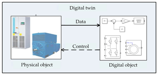
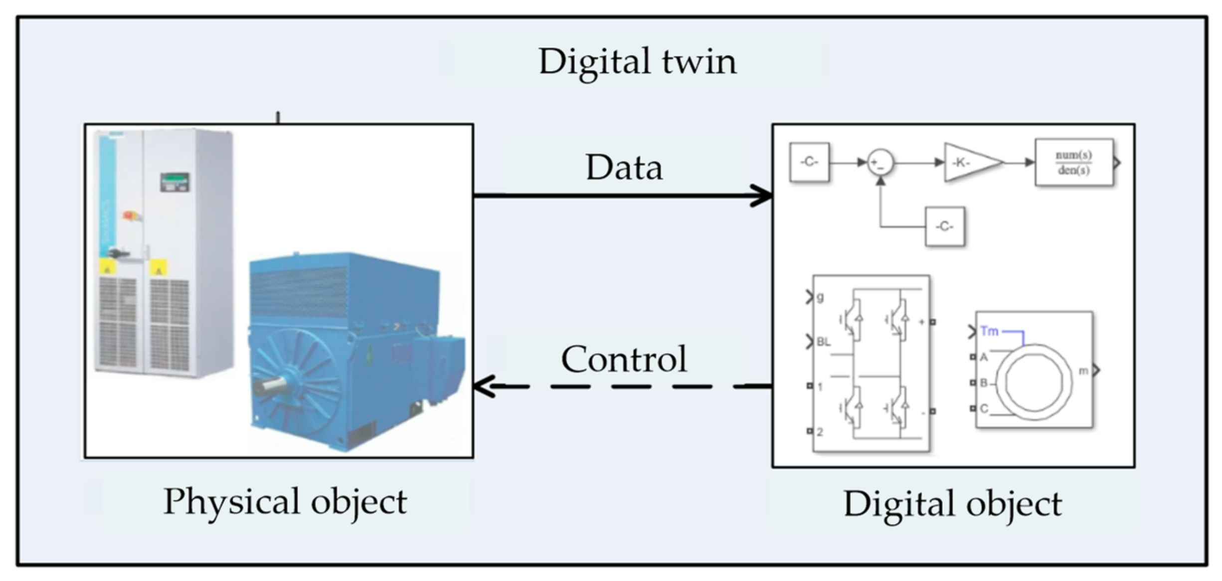
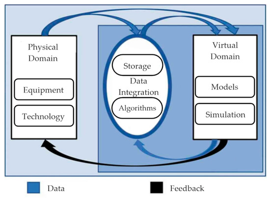
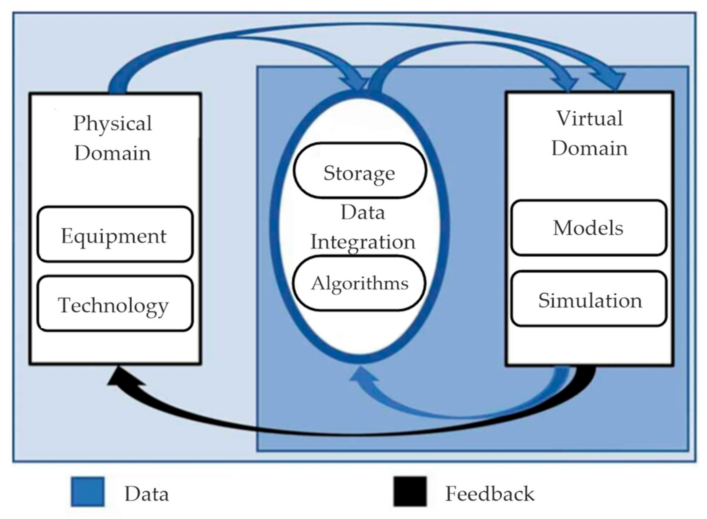
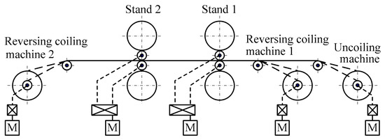
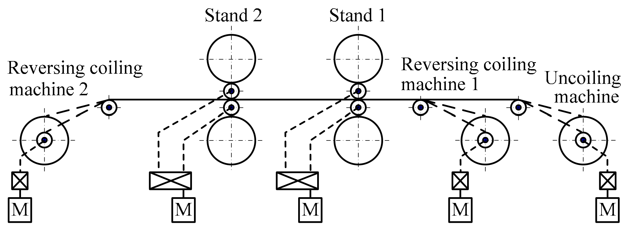
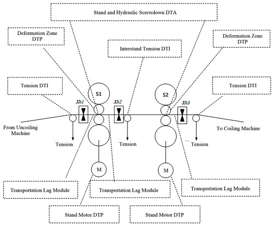
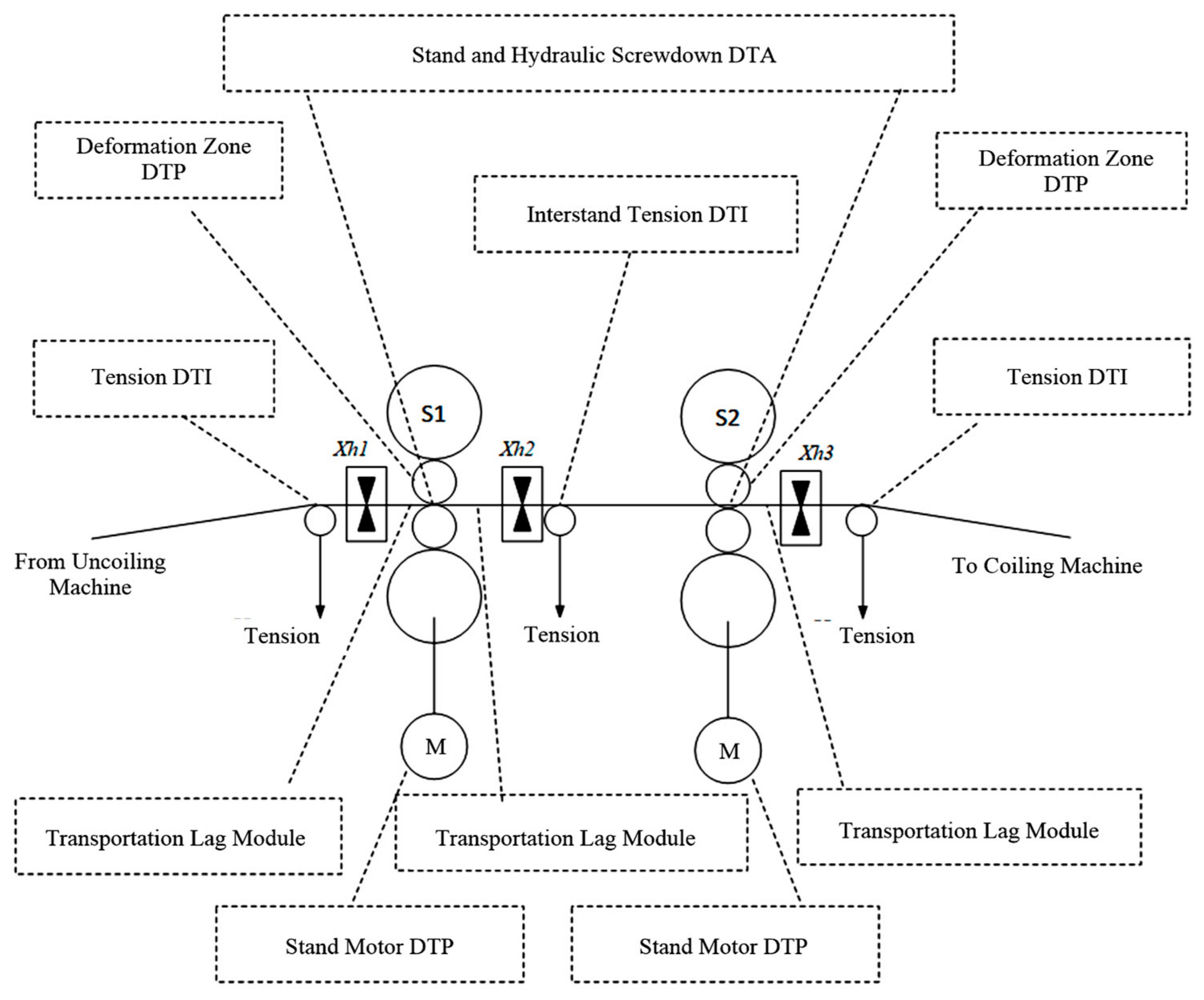
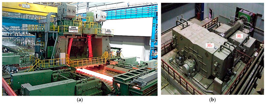
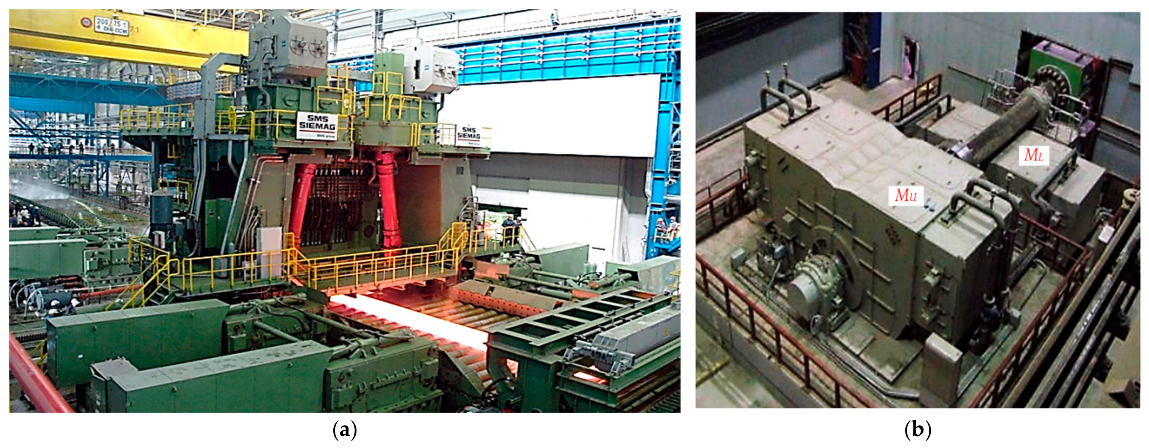
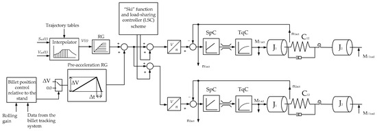
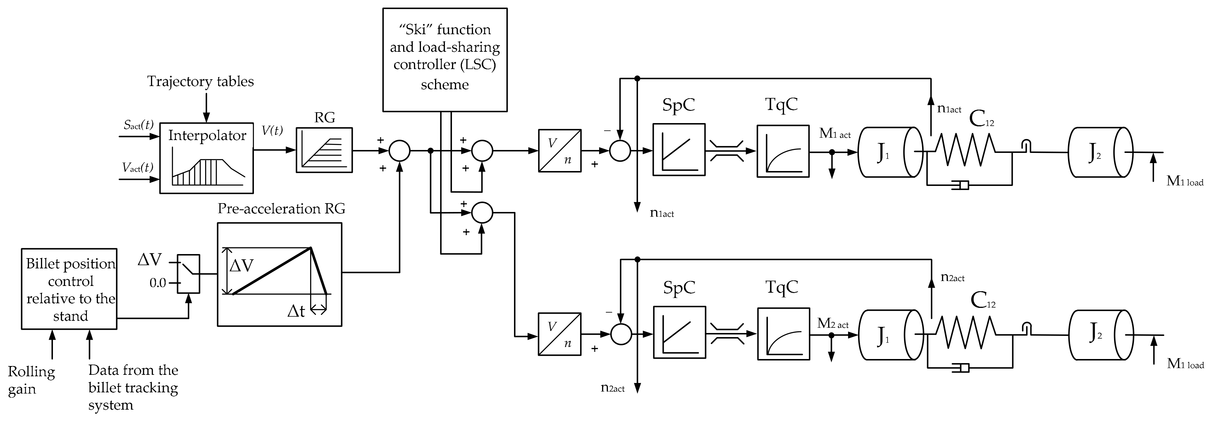
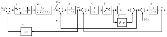
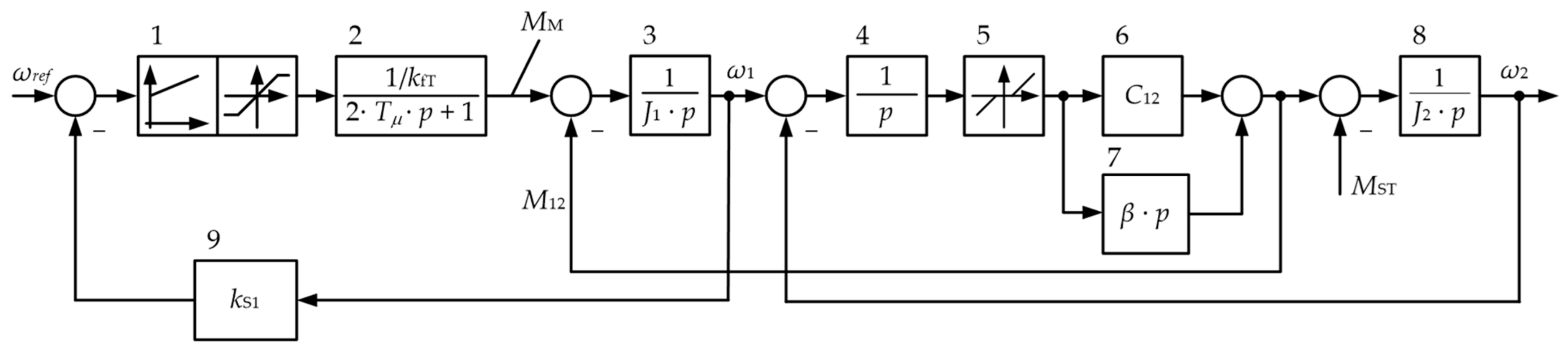
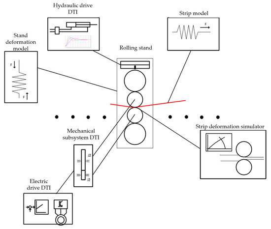
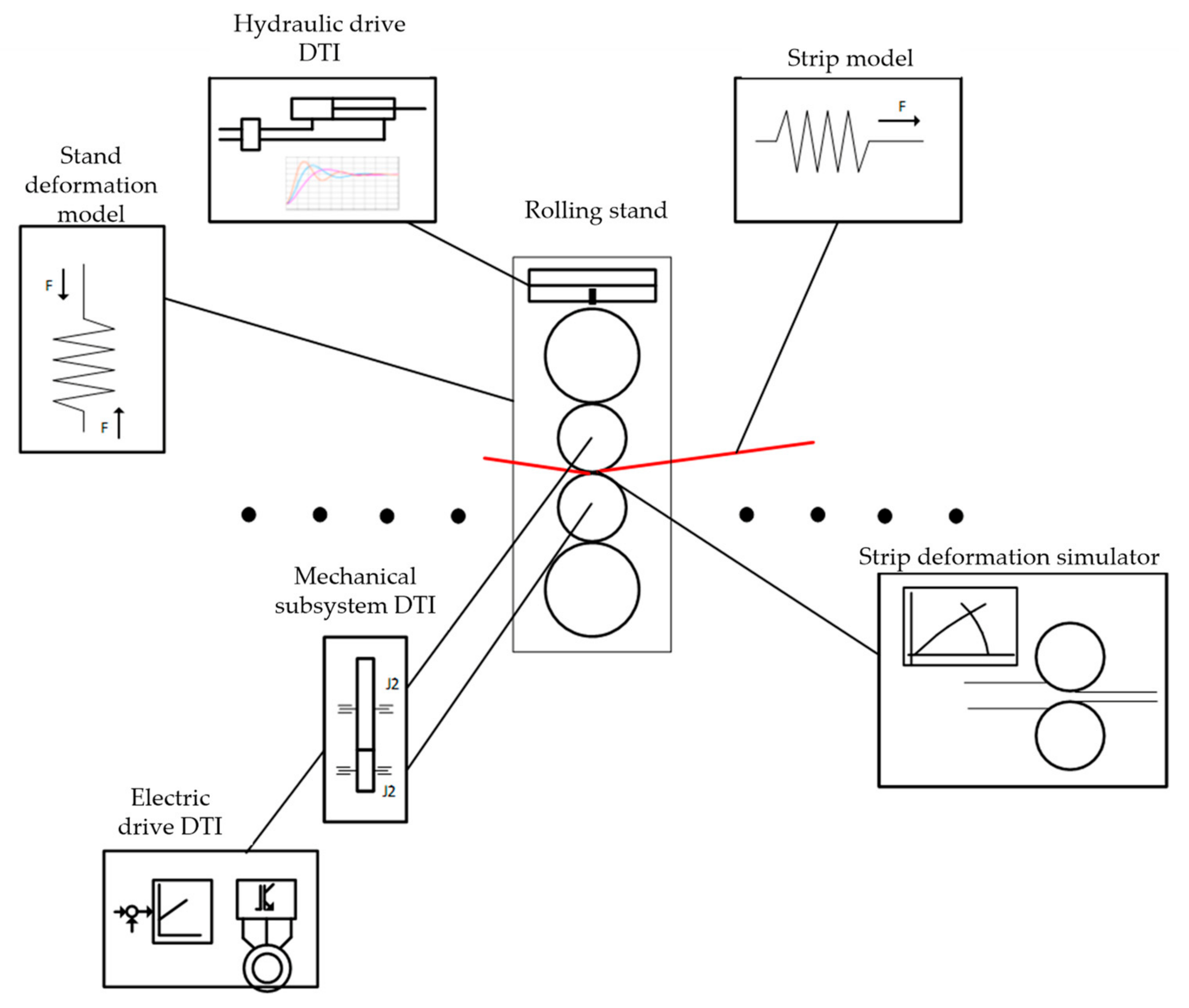
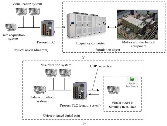
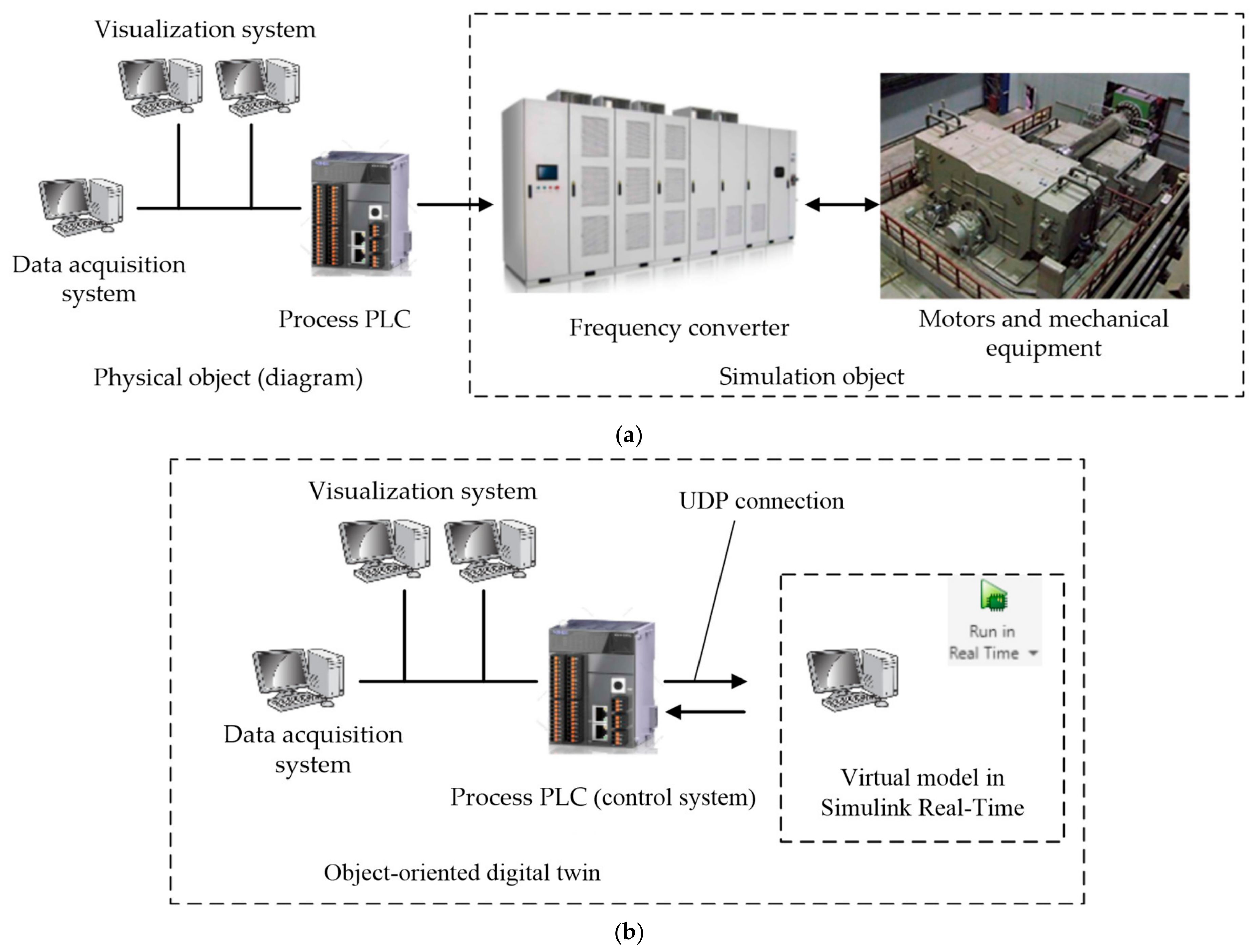
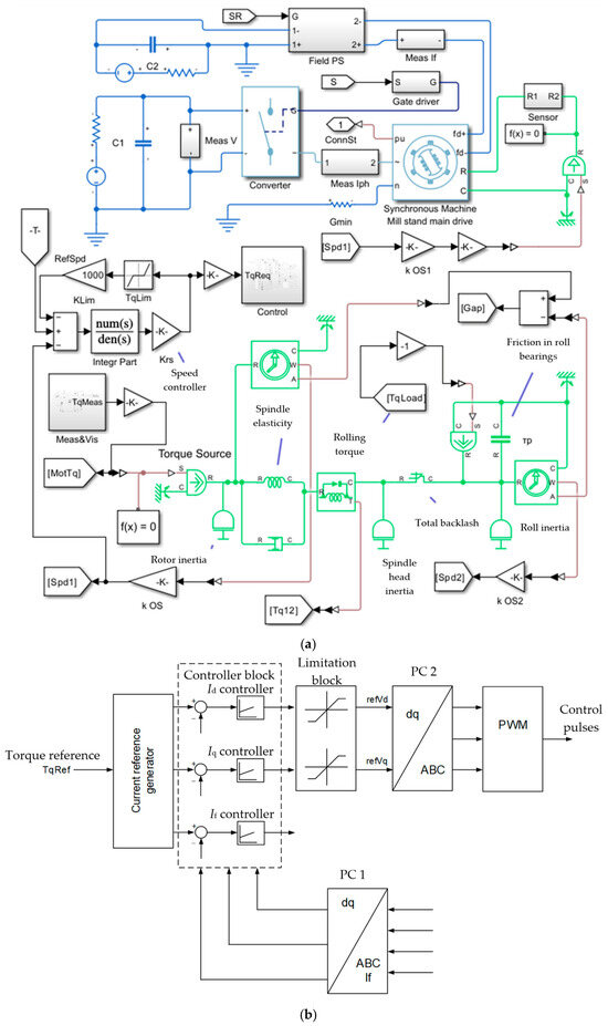
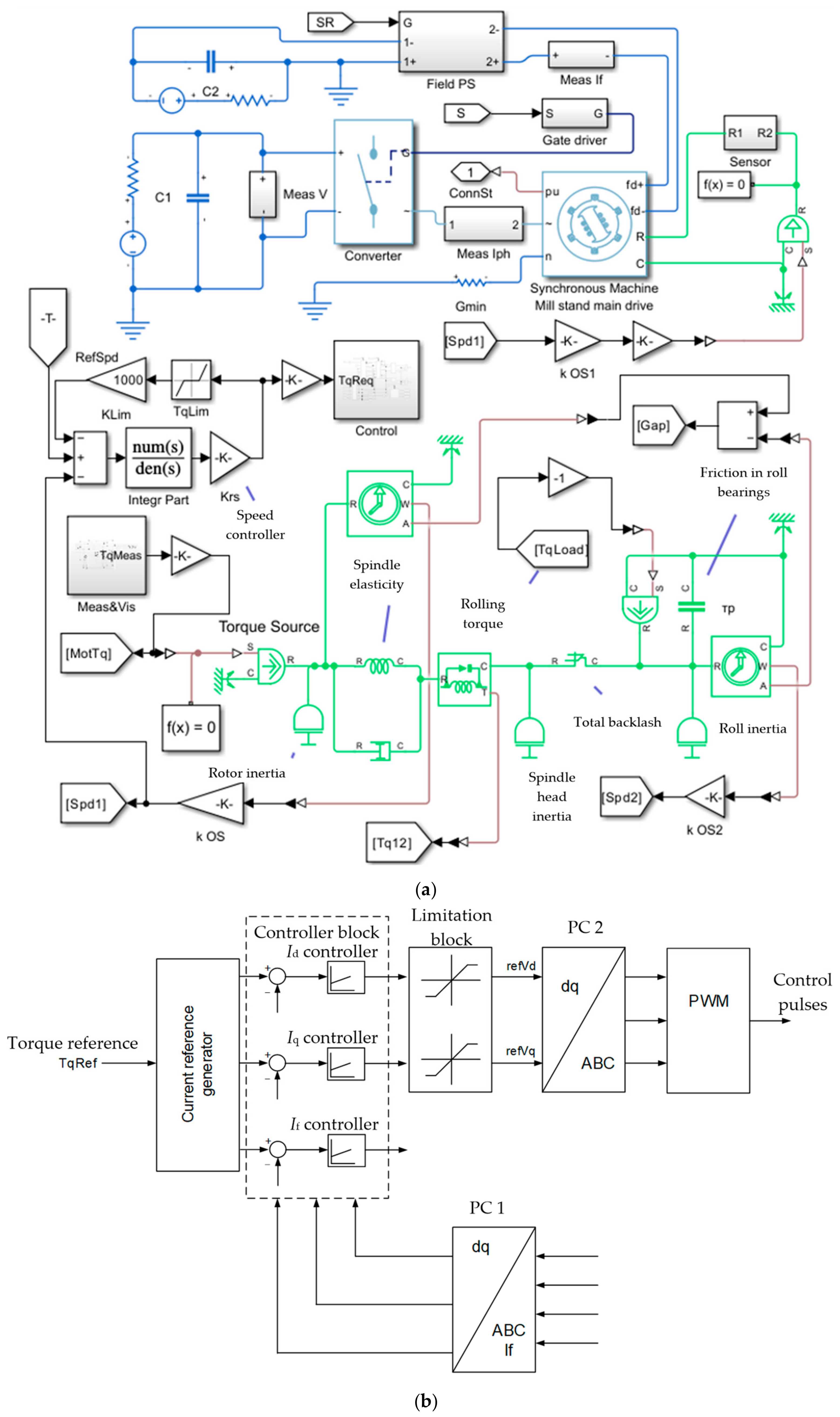
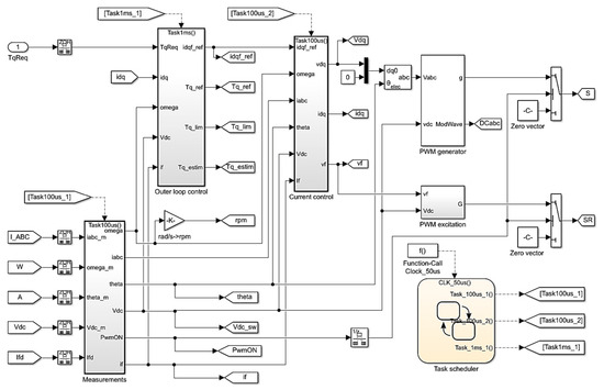
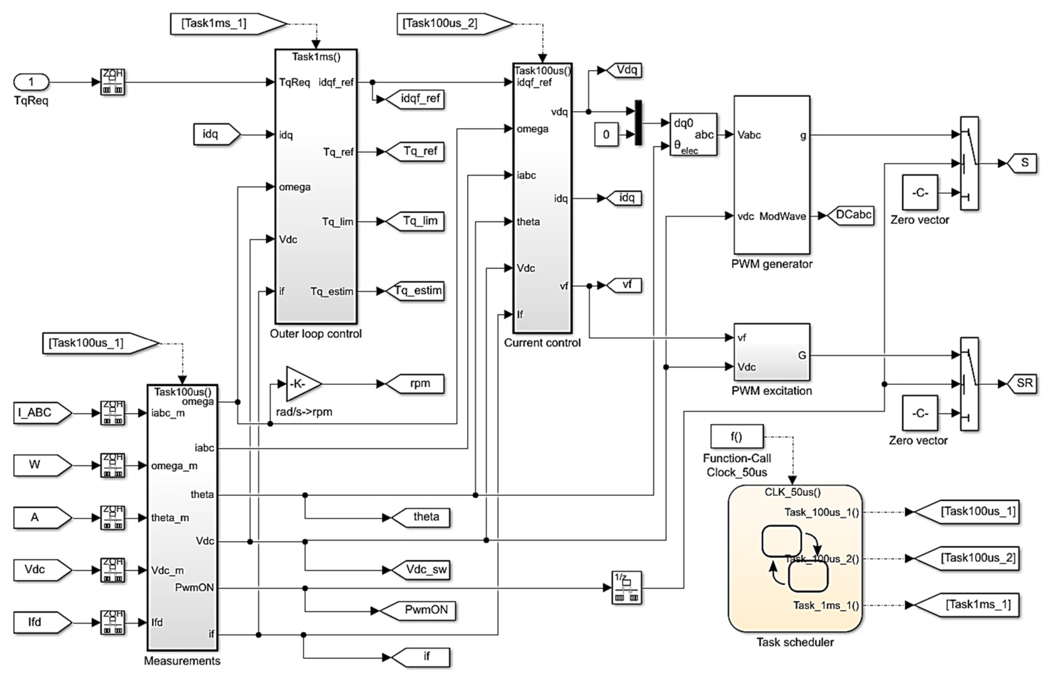
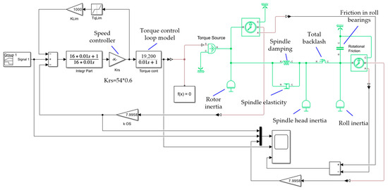
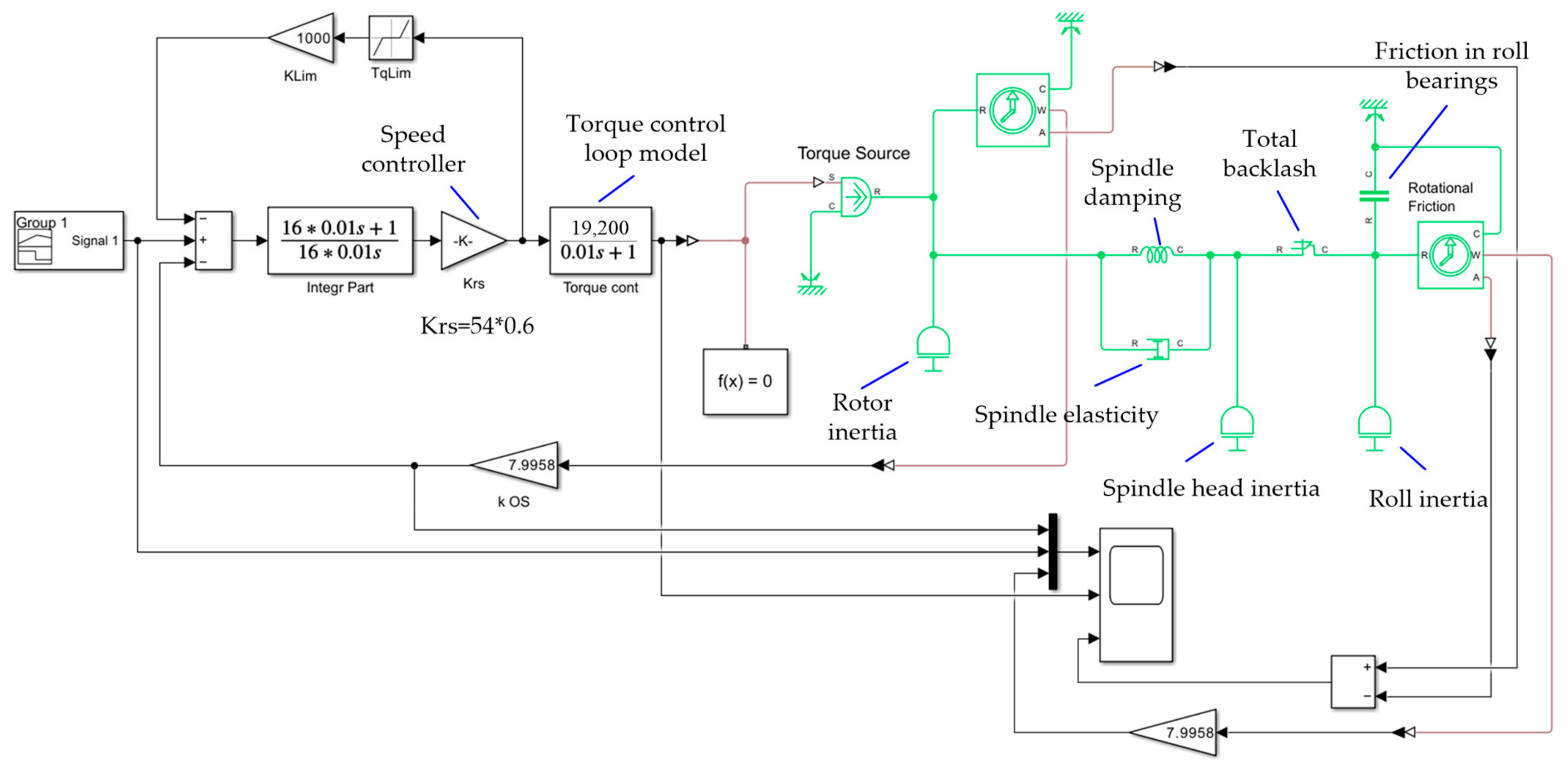
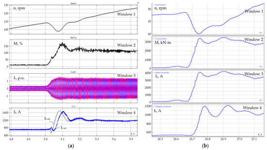
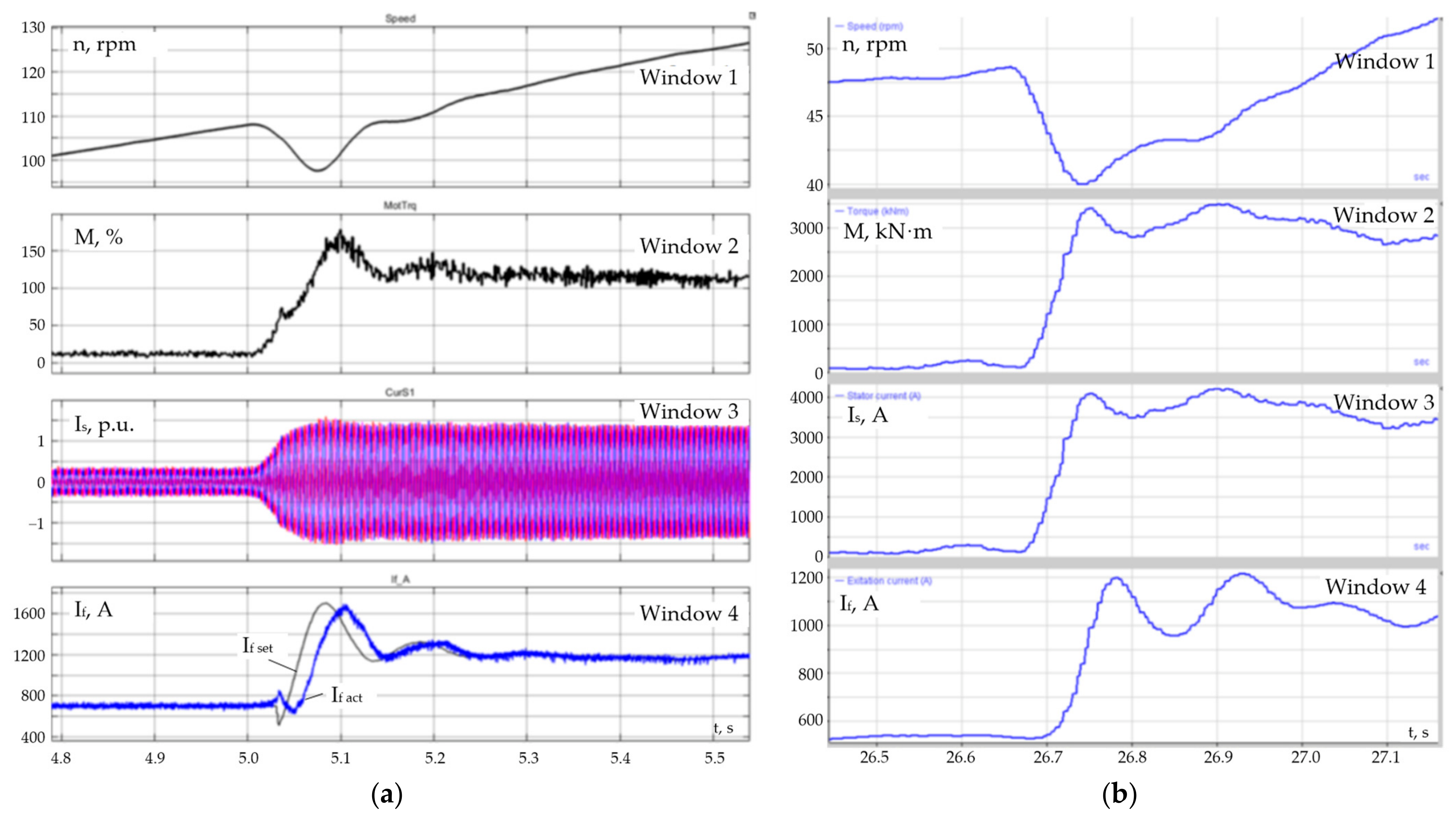
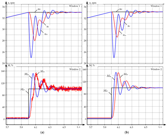
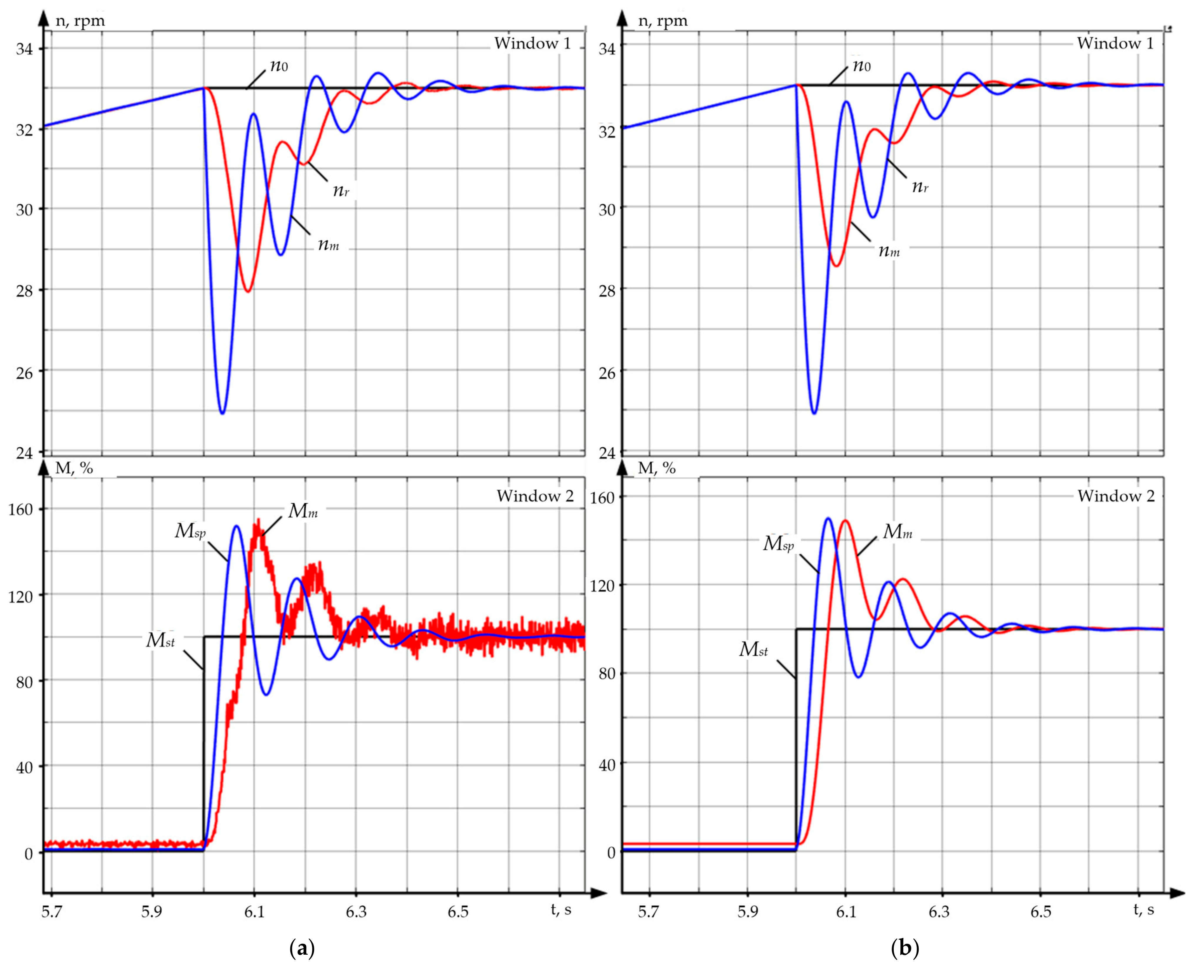
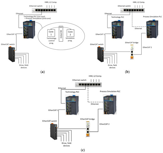
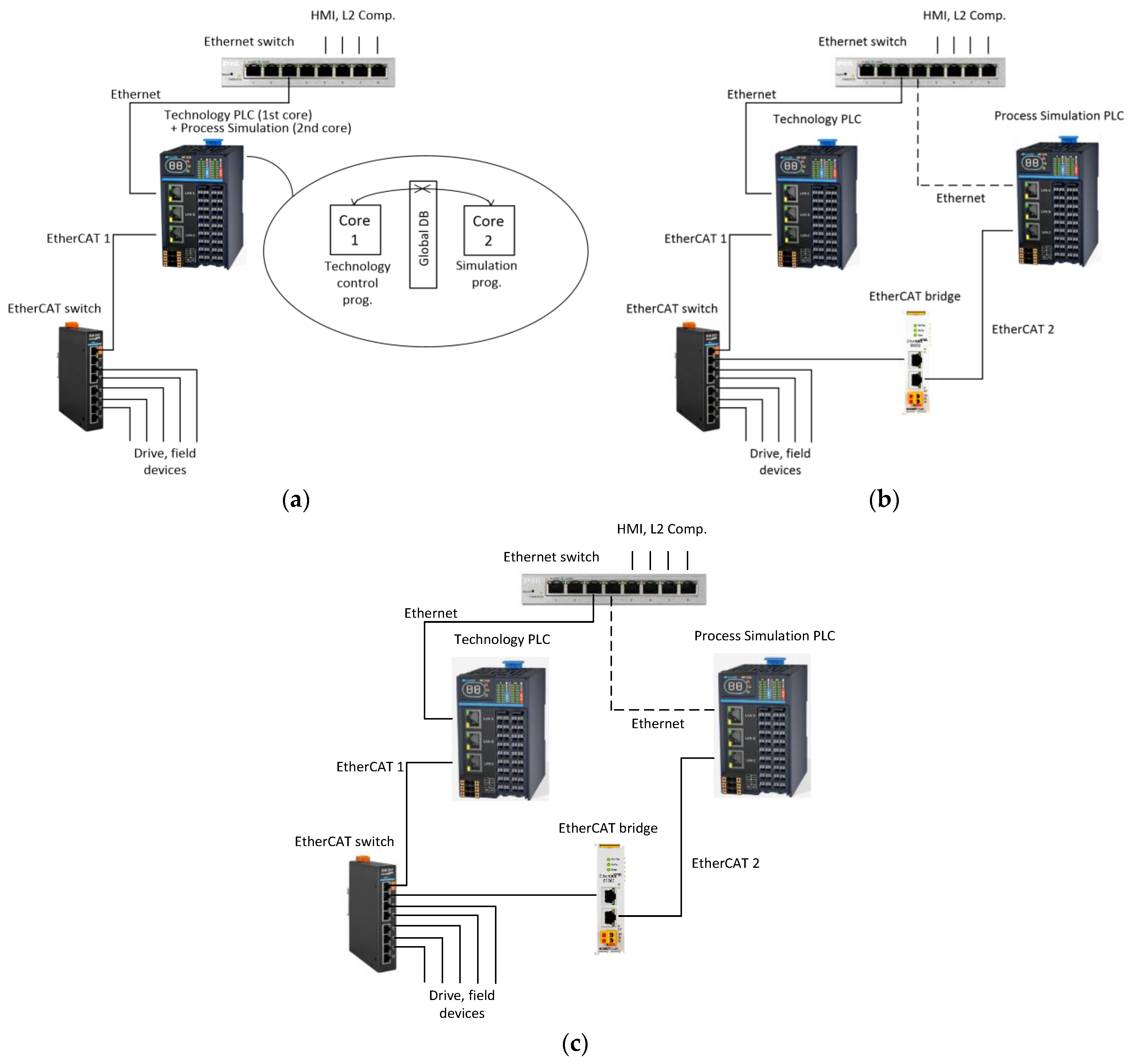
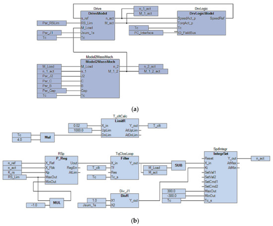
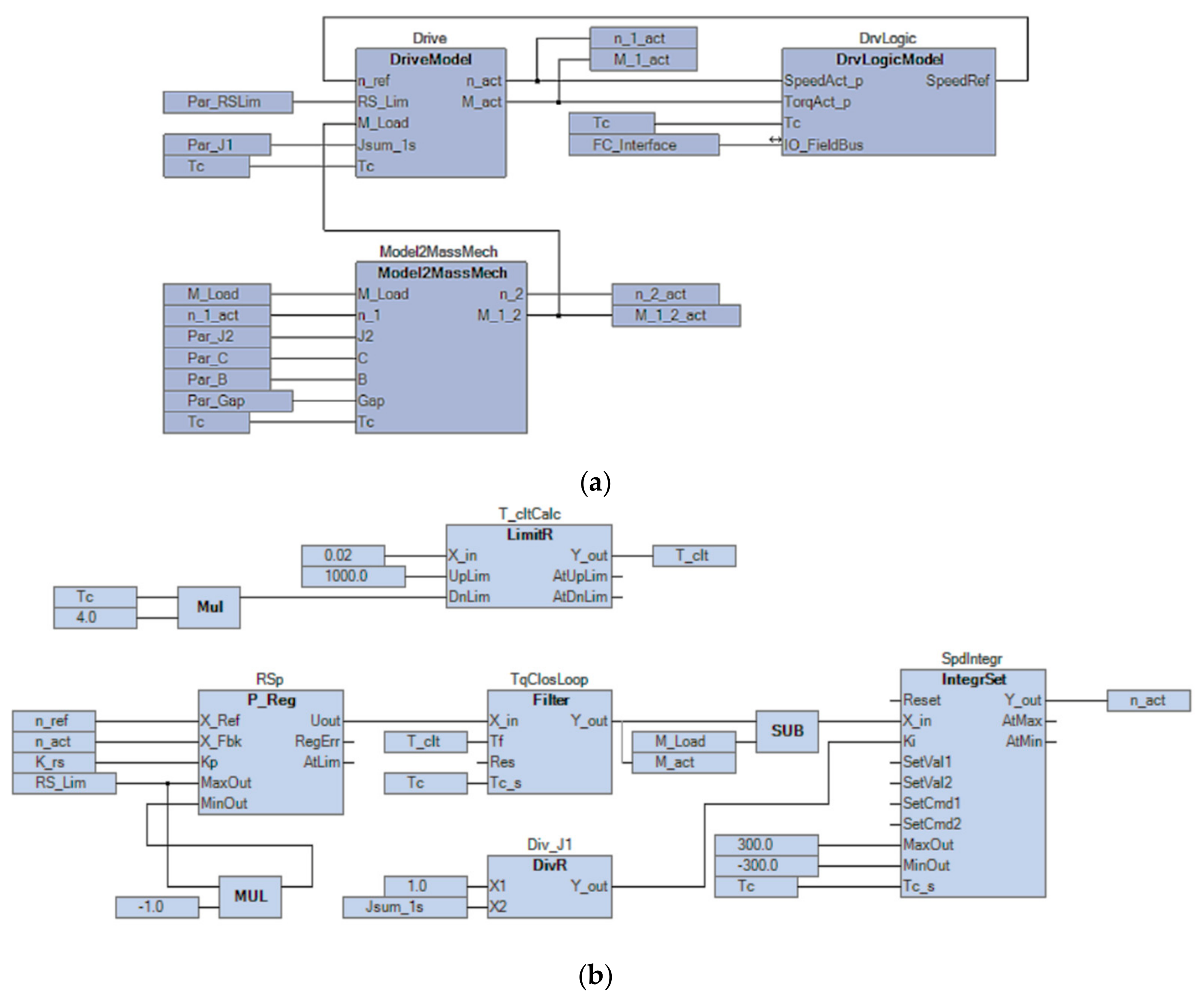
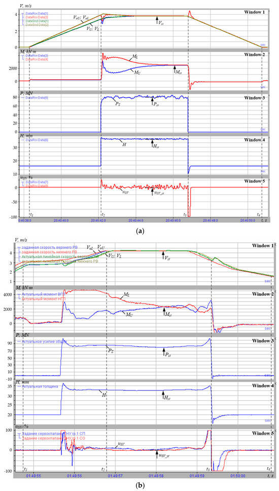
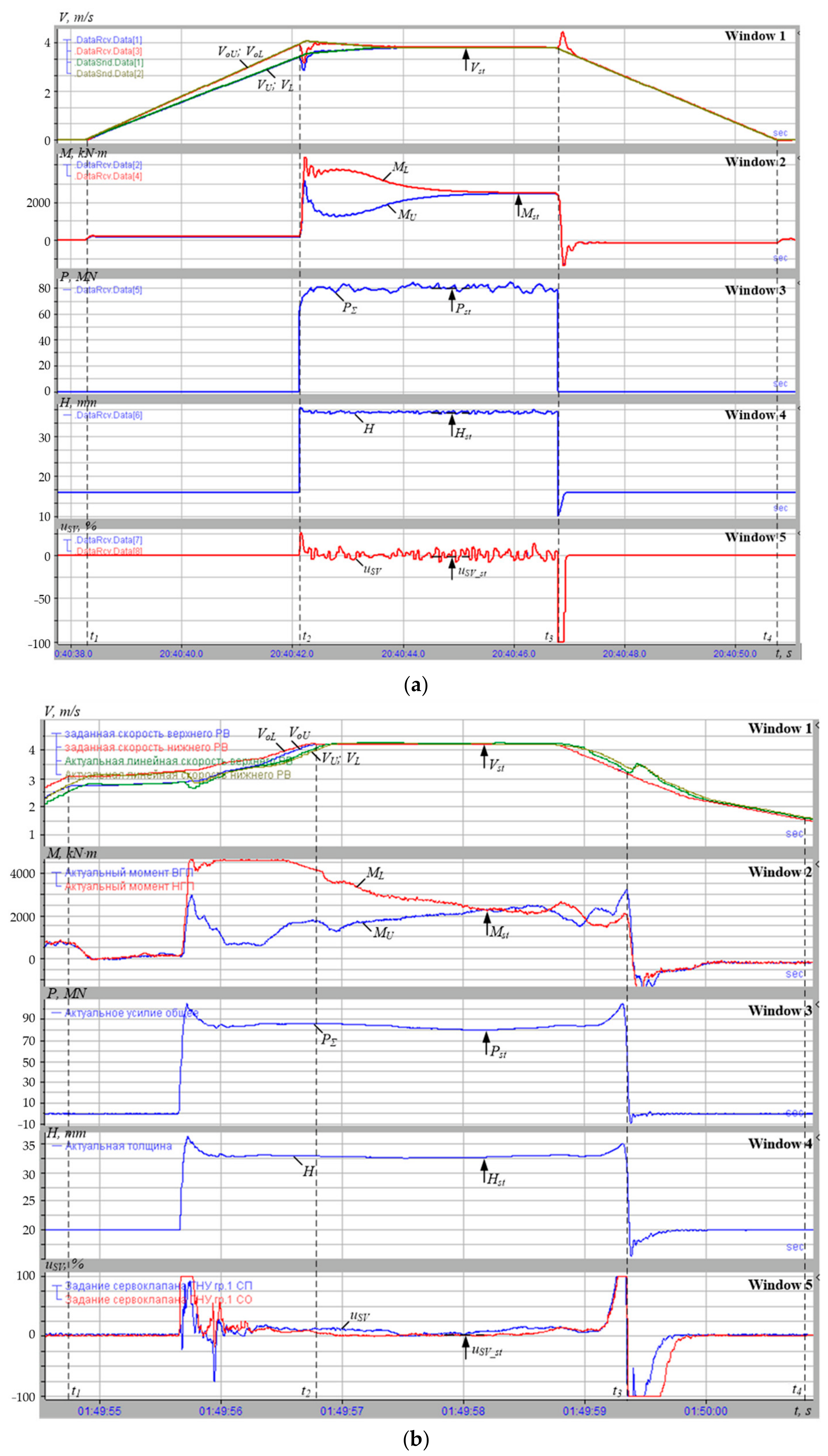

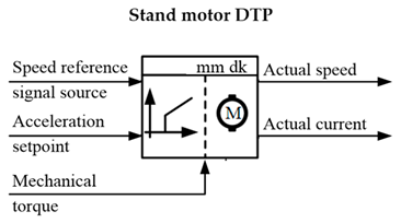
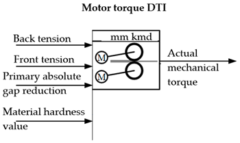
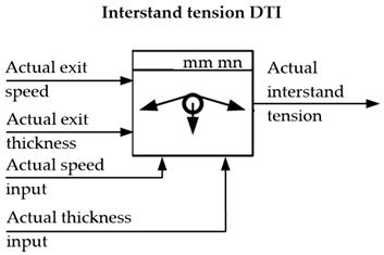
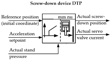
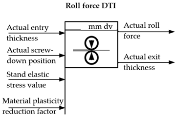
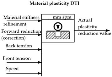
Disclaimer/Publisher’s Note: The statements, opinions and data contained in all publications are solely those of the individual author(s) and contributor(s) and not of MDPI and/or the editor(s). MDPI and/or the editor(s) disclaim responsibility for any injury to people or property resulting from any ideas, methods, instructions or products referred to in the content. |
© 2026 by the authors. Licensee MDPI, Basel, Switzerland. This article is an open access article distributed under the terms and conditions of the Creative Commons Attribution (CC BY) license.