


Abstract
This study numerically investigates the thermal–hydraulic performance of sharp-nose tube profiles for heat exchanger applications. Six geometries, including rounded and sharp-nose tubes with angles ranging from 20° to 45°, were analyzed at inlet velocities of 4 m/s and 12 m/s (Re = 7895–23,685). A thermal–hydraulic performance metric was used to evaluate the proposed designs against a drop-shaped tube. The results indicate that sharp-nose and double-nose profiles exhibit enhanced performance by 4–25% compared to the drop-shaped tube. The optimal configuration with a nose angle of achieves the highest improvement in the thermal–hydraulic performance metric by 25.3% compared to the drop-shaped tube at Re = 7895. At lower Reynolds numbers, all sharp-nose configurations outperform the drop-shaped geometry, while performance converges at higher angles due to geometric similarity. The findings indicate that values calculated by employing the area-weighted average skin friction coefficient and the associated flow separation behavior play a central role in determining the thermal–hydraulic performance of the tube profiles. These findings highlight the potential of sharp-nose geometries for heat exchanger performance enhancement.
1. Introduction
Heat exchangers employing tube banks are widely used in thermal systems due to their effectiveness in transferring heat between fluids in cross-flow configurations. Traditionally, circular tubes have dominated industrial applications; however, their aerodynamic limitations and tendency for early boundary-layer separation have motivated researchers to explore alternative tube geometries that enhance thermal–hydraulic performance. In recent years, drop-shaped and other non-circular tubes have emerged as promising candidates due to their ability to reduce drag, delay flow separation, and augment heat transfer under various operating conditions. Driven by the need for more efficient and compact thermal systems, recent studies have explored various passive enhancement techniques, including the use of airfoil-inspired geometries, vortex generators, and optimized roughness elements. The literature provided highlights significant advancements in printed circuit heat exchangers (PCHE), solar air heaters, tube heat exchangers, and fundamental fluid dynamics over bluff bodies.
Recent advances in passive heat transfer enhancement techniques have focused on geometric modification of flow passages, including airfoil-based inserts, vortex generators, and optimized surface roughness elements. Li et al. [1] investigated a fractal structure featuring symmetric (NACA 0021) and asymmetric (NACA 4822) airfoil fins within the smooth channels of the printed circuit heat exchanger (PCHE). Their numerical analysis revealed that while both fin designs significantly improved heat transfer compared to smooth channels, the asymmetric airfoil fin channel exhibited superior performance, with a comprehensive evaluation index enhancement factor ranging from 1.05 to 3.76. The study emphasized that optimal heat transfer relies on the apt matching of flow rates between hot and cold channels rather than merely high fluid flow rates.
Similarly, Sanjay Kumar et al. [2] examined the influence of rib roughness geometry in solar air heaters, comparing conventional rectangular ribs with streamlined reverse NACA0020 profiles. Their findings revealed that streamlined geometries effectively reduce flow separation, resulting in higher Nusselt numbers and lower friction factors, thereby achieving superior thermo-hydraulic performance. The thermo-hydraulic performance parameter (THPP) of 2.21 at a Reynolds number of 6000 outperformed that of bluff bodies in both thermal efficiency and exergy efficiency.
Deeb [3] examined the potential enhancement of the efficiency of bundles consisting of drop-shaped tubes by adjusting the attack angle () within the range of 0 to 360. A comparative analysis was conducted between eight configurations of drop-shaped tube bundles and their circular counterparts. The findings showed that case 8 of a drop-shaped tube bundle () had a higher average Nusselt number values compared to case 4 of a staggered drop-shaped bundle at The friction factor of the staggered (case 4) and in-line (case 2) cases is lower in comparison to the staggered (case 3) and in-line (case 1) bundles of circular tubes. The maximum values of thermal–hydraulic performance were achieved in case 6 () and were higher than for both case 3 and case 1. Empirical correlations of the average Nusselt number, friction factor and overall performance for the energy-efficient tube bundle in terms of Reynolds number were derived from the simulation data.
Deeb and Sidenkov [4,5] conducted comprehensive numerical investigations on turbulent flow and heat transfer over drop-shaped tubes. In their study of a three-row staggered tube bundle using ANSYS 2019R1, they reported that the configuration at an angle of attack of 0° achieved the highest thermal–hydraulic performance, followed by 180°, with performance levels significantly exceeding those of circular tube bundles by approximately 16.18~18.19% and 9.94~10.43%, respectively. They also developed correlations for the friction factor as functions of Reynolds number and angle of attack, considering both un-deformed and deformed tube cross-sections. Furthermore, they evaluated the performance of five two-equation turbulence models for predicting flow and heat transfer over single and bundled drop-shaped tubes, comparing the numerical results with experimental data. Their findings indicated that the RNG k–ε model with enhanced wall treatment provides the most accurate predictions, yielding a maximum deviation of only 5.89% for the average Nusselt number in drop-shaped tube bundles.
An experimental and numerical investigation by Deeb [6] examined the effect of angle of attack on fluid flow characteristics around a single drop-shaped tube for a range of angles of attack (). He compared the results of the drop-shaped tube with those of a circular tube having the same equivalent diameter. The drop-shaped tube outperforms the circular tube by achieving lower drag and friction factors under identical operating conditions. Within the angular ranges of and , the drop-shaped tube experiences a stronger favorable pressure gradient at the front, which delays flow separation from the wall compared to the circular tube.
Deeb and Sidenkov [7,8] performed detailed numerical investigations on heat transfer and fluid flow over circular and non-circular tube geometries. Their results demonstrated that, for all studied configurations, the average Nusselt number increases while the friction factor decreases with increasing Reynolds number. Among the investigated shapes, the drop-shaped tube exhibited the highest thermal–hydraulic performance, followed by cam, elliptical, flat, and circular tubes, respectively, with the drop-shaped geometry consistently yielding superior heat transfer coefficients and Nusselt numbers. In a subsequent study, they examined the influence of axis ratio (L/D = 1–4) on the performance of single drop-shaped tubes in cross-flow, where L/D = 1 corresponds to a circular tube. The findings revealed that decreasing the axis ratio leads to a reduction in the minimum pressure coefficient and the maximum friction coefficient, while the overall friction factor decreases with increasing Reynolds number and axis ratio. Additionally, empirical correlations for the average Nusselt number and friction factor were developed as functions of Reynolds number and axis ratio, providing practical tools for the design and optimization of non-circular tube heat exchangers.
In double-pipe heat exchangers, the incorporation of passive enhancement devices such as tabulators is a well-established technique for improving thermal performance. Thejaraju et al. [9] introduced an innovative para-winglet tape (PWT) insert designed to promote swirl flow, increase turbulent kinetic energy, and generate longitudinal vortices within the flow passage. Their experimental investigation, conducted over a Reynolds number range of 6000–30,000, demonstrated a substantial enhancement in convective heat transfer. The study is extended to evaluate the overall thermo-hydraulic performance using the Performance Optimization Index (POI), which was found to increase with Reynolds number. This trend indicates that the effectiveness of PWT inserts becomes more pronounced under higher flow rate conditions, making them particularly suitable for turbulent flow regimes in practical heat exchanger applications.
Beyond specific geometrical modifications, fundamental studies on flow over circular cylinders provide valuable insight into the intrinsic relationship between aerodynamic drag and convective heat transfer. Ma and Duan [10] challenged the conventional definition of the drag coefficient, proposing a new “appropriate drag coefficient” () that better reflects the physical behavior of drag force over a wide range of Reynolds numbers. They established a strong analogy between drag and heat/mass transfer, developing a correlation that allows the Nusselt number to be predicted from drag data. This finding provides a simplified theoretical basis for predicting heat transfer characteristics in complex flows, including those over high-speed aircraft structures.
A numerical investigation by Deeb and Sidenkov [11] examined the thermal and fluid flow characteristics of staggered arrays of circular and double drop-shaped tube bundles. The results showed that the drop-shaped tubes provide better heat transfer characteristics, and a lower friction factor as compared to that of the circular tubes, and as a result the thermal–hydraulic performance of this tube bank is greater than that of the circular tube. In the case of drop-shaped tubes, due to more clearance (longitudinal spacing between rows), the friction factor and the efficiency are higher. Accordingly, considering both thermal and hydrodynamic performance, the drop-shaped tube bundle demonstrates clear superiority over the circular tube bundle.
Gururatana and Skullong [12] experimentally investigated a “Modified NACA0024” insert mounted on a straight tape within a circular tube. They found that the insert generated longitudinal vortices that significantly increased turbulent mixing. The study determined that a 45° inclination angle offered the best heat transfer enhancement performance (HTEP), achieving a maximum value of 1.45 at a Reynolds number of 4196, with heat transfer rates approximately three times higher than that of a plain tube.
Ahmed et al. [13,14] conducted comprehensive experimental and numerical investigations on the thermo-hydraulic performance of cross-flow heat exchangers employing staggered wing-shaped tubes at various angles of attack. Their findings revealed that the pressure drop coefficient increases with the angle of attack in the range of 0° to 45°, while it decreases for higher angles between 135° and 180°, reflecting the strong dependence of flow separation and wake formation on tube orientation. In terms of heat transfer characteristics, the Nusselt number was found to increase with Reynolds number, whereas the Stanton number exhibited a decreasing trend. Furthermore, heat transfer performance improved with an increasing angle of attack up to 45°, beyond which it deteriorated due to intensified flow separation at larger angles. The optimal thermal performance and overall heat exchanger effectiveness were achieved at lower Reynolds numbers and near-zero angles of attack. Additionally, empirical correlations for both the Nusselt number and Stanton number were developed as functions of the Reynolds number and angle of attack, providing practical design tools for wing-shaped tube heat exchangers.
Understanding near-wall flow behavior is essential for the design of compact heat exchangers, where components are often closely spaced and wall effects become significant. Murthy and Gupta [15] experimentally investigated the flow and heat transfer characteristics over an NACA0018 airfoil in a wind tunnel to evaluate the influence of wall proximity. The study considered variations in the height ratio (y/H) and the angle of attack. The results showed that as the airfoil approached the upper wall (i.e., with decreasing y/H), the pressure coefficient, drag coefficient, and both local and average Nusselt numbers decreased. Furthermore, the maximum average Nusselt number was observed at an angle of attack of 40°, highlighting the significant impact of wall proximity on both aerodynamic and thermal performance.
A substantial body of research has examined the influence of tube geometry on flow behavior and heat transfer characteristics. Comparative studies [7] between circular and various non-circular profiles have consistently demonstrated that drop-shaped tubes achieve higher average Nusselt numbers and heat transfer coefficients, while simultaneously exhibiting lower friction factors. Furthermore, experimental and numerical investigations [6] have highlighted the critical role of the angle of attack in governing the flow structure around drop-shaped tubes. These studies confirm that, at low angles of attack (0–20° and 160–180°), the presence of a favorable pressure gradient delays boundary-layer separation, thereby reducing aerodynamic drag more effectively than in equivalent circular tubes and enhancing overall thermal–hydraulic performance.
Further investigations offered by Deeb and Sidenkov [16] into geometric refinement have examined tubes with varying axis ratios (L/D = 1–4), establishing that an increasing axis ratio or Reynolds number leads to a systematic reduction in the friction factor and improved pressure-coefficient behavior. In tube bundles, staggered drop-shaped arrangements [17] at attack angles of 0° and 180° outperform circular tube bundles in terms of thermal–hydraulic performance by substantial margins, and correlations for friction factor based on the Reynolds number and angle of attack have been proposed.
Efforts to optimize bundle-level performance (Deeb [18]) through orientation scheduling across 0–360° have revealed specific combinations of tube orientations capable of substantially enhancing heat transfer while reducing friction losses. In this study, a comparative analysis was conducted between eight configurations of drop-shaped tube bundles and their circular counterparts. Selected optimized drop-shaped bundle cases exhibit superior Nusselt numbers and markedly improved thermal–hydraulic performance relative to both circular tube bundles and conventional staggered or inline configurations. Empirical correlations provide guidance for designing energy-efficient tube banks.
Accurate numerical prediction of flow and heat transfer over such geometries is highly dependent on the appropriate selection of turbulence models. Deeb and Sidenkov [5] conducted comparative assessments of two-equation turbulence models and demonstrated that certain model variants can reliably predict the average Nusselt number of drop-shaped tube bundles with relatively low error, highlighting the importance of turbulence model selection in simulating complex separated flows around streamlined geometries. Deeb [19] numerically investigated the thermal and fluid flow behavior in the case of circular and double drop-shaped tube bundles with a staggered arrangement, showing that the drop-shaped tubes provide better heat transfer characteristics and a lower friction factor as compared to those of the circular tubes. As a result, the thermal–hydraulic performance of this tube bank is greater than that of the circular tube. In the case of drop-shaped tubes, due to more clearance (longitudinal spacing between rows), the friction factor and the efficiency are higher. Consequently, both thermal and hydrodynamic parameters indicate that overall the drop-shaped tube bundle is superior to the circular tube bundle.
Previous studies have mainly focused on rounded and streamlined tube geometries for heat exchangers, while sharp-nose profiles and the effect of nose angle on flow and heat transfer remain insufficiently explored. Therefore, the main objective of the present study is to examine the effect of nose angle on the combined flow and heat transfer characteristics by carrying out numerical investigation of sharp-nose tubes with angles from 20° to 45°, comparing their thermo-hydraulic performance with optimized rounded profiles. In the sections that follow, the numerical analysis methodology is presented along with proof of its robustness and validity. Next, the Results and Discussion Section presents the findings along with a comparison of the combined thermal–hydraulic performance between different tube geometries. Finally, the study ends with the main conclusions.
2. Methodology
2.1. Geometry and Configurations
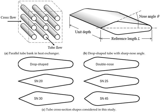
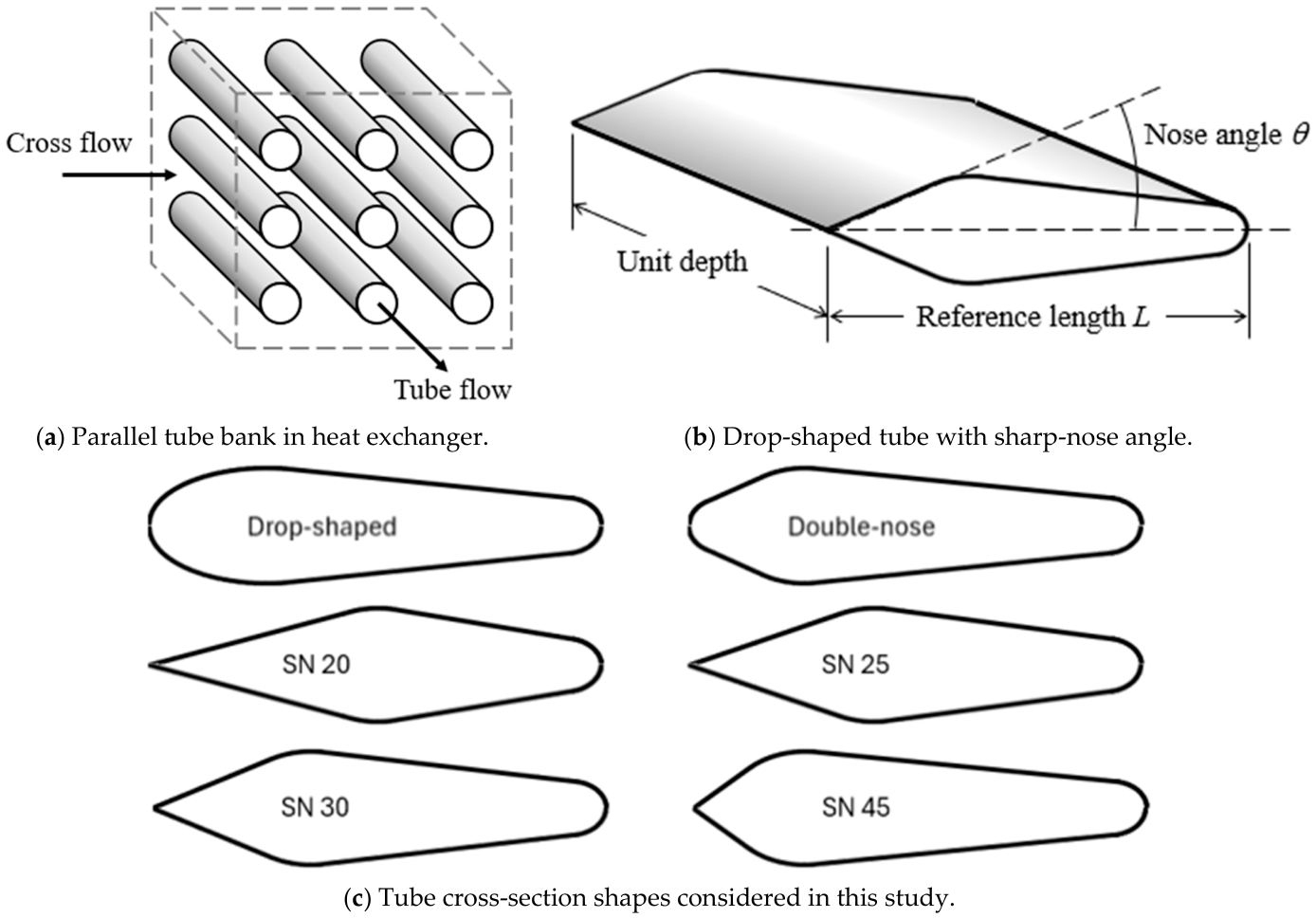
Existing heat exchangers typically employ circular cross-section tubes for heat transfer as shown in Figure 1a. In this study, the heat transfer and flow characteristics of non-circular shaped tubes, shown in Figure 1b, with different round- and sharp-nose cross-sections are investigated. Figure 1c shows the six different cross-section geometries with round and sharp noses that were analyzed. These cross-sections include: drop-shaped, double-nose-shaped and four cross-sections with sharp-edged noses designated as SNxx, where the number xx indicates the nose half-angle as shown in Figure 1b. Several studies in the literature consider round-shaped cross-sections. For example, the drop-shaped cross-section has been analyzed by Deep and Sidenkov [1]. It has been included in the present study for validation and performance comparison. All geometries have the same characteristic reference length of 0.03063 m and maximum cross-section heights.
Figure 1.
Tubes in a typical cross-flow heat exchanger: (a) parallel tube bank, (b) drop-shaped tube with sharp-nose angle, and (c) cross-section shapes of tubes considered in this study along with their designations.
2.2. Governing Equations and Turbulence Modeling
The numerical analyses are performed with ANSYS Fluent using the RANS formulation. In addition to conventional RANS-based CFD approaches, alternative numerical methods such as the lattice Boltzmann method (LBM) and hybrid FVM–LBM frameworks have gained increasing attention for simulating heat exchanger applications, particularly due to their ability to handle conjugate heat transfer, complex geometries, multiphase interactions and microscale effects [20,21,22,23,24,25]. However, in this study, the two-dimensional forms for the steady, incompressible Reynolds-Averaged Navier–Stokes (RANS) equations representing the mass, momentum and energy conservation laws are employed. These are expressed as follows:
Continuity Equation:
Momentum Equation:
Energy Equation:
The Shear Stress Transport (SST) k–ω model with advanced wall treatment is used for turbulence closure. The mesh is constructed to satisfy y+ < 1 along the tube surface, enabling direct resolution of the viscous sublayer and accurate prediction of wall shear and heat transfer. The SST k–ω transport equations are:
k-equation:
ω-equation:
Eddy viscosity formulation:
Production term limiter:
Blending functions (standard SST):
Cross-diffusion term:
Model coefficients (standard values):
The blending functions and govern the transition between k–ω (near-wall) and k–ε-like (free-stream) behavior. activates k–ω close to the wall ( → 1), delivering accurate viscous-sublayer and log-layer resolution—particularly effective with y+ < 1. blends the model toward k–ε away from the wall ( → 1), stabilizing free-stream turbulence levels and preventing contamination from ω. Separation prediction is improved through: (i) the shear-stress limiter , which avoids excessive eddy viscosity and artificial attachment, (ii) direct near-wall resolution that captures adverse-pressure-gradient effects and skin-friction changes, and (iii) robust free-stream behavior that preserves wake structures. These features make SST k–ω well suited for assessing how variations in nose angle strongly influence separation, reattachment, and heat transfer performance.
2.3. Computational Domain and Boundary Conditions
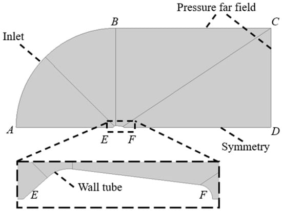
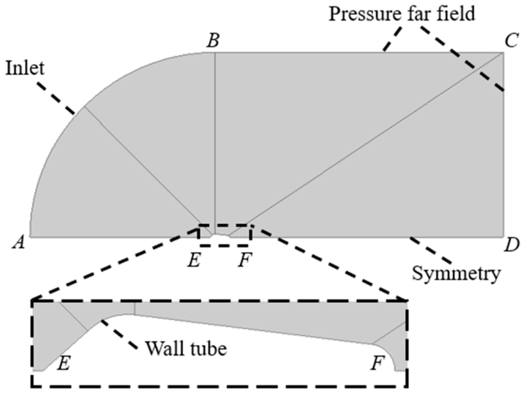
Figure 2 illustrates the symmetric upper half of the computational domain (approximately 0.8 m × 0.3 m in size) with different boundary conditions that include: (1) velocity inlet AB, (2) pressure far-field (outlet) boundaries BC and CD, (3) flow symmetry boundaries AE and FD, and (4) solid wall boundary EF representing the symmetric upper half surface cross-section of the tube. The simulations are formed at two different flow velocities of 4 and 12 m/s. Table 1 lists the simulation conditions common to all cases at the two flow velocities. Air properties are evaluated at 299 K and 1 atm. Table 1 also lists the turbulent intensity and hydraulic diameter for the velocity inlet and pressure outlet boundaries used in the analysis.
Figure 2.
The computational domain with different boundary conditions.
Table 1.
The simulation conditions common to all cases.
Ideally, the best choice would be to use conjugate heat transfer boundary conditions for performance evaluation of heat exchangers. However, it cannot be implemented in the current study since the tube thickness has not been considered. An alternative to the use of a conjugate heat transfer model is the use of a uniform heat flux boundary condition if the objective is to purely study flow physics; another is to develop Nusselt number correlations. Since the objective of the study is to determine the heat transfer characteristics of different tube shapes by comparing the tube surface Nusselt number characteristics, the tube cross-section wall EF is subjected to a uniform heat flux of 2000 W/m2.
The six tube cross-section shapes shown in Figure 1c are analyzed at the two different flow velocities of 4 and 12 m/s corresponding to the Reynolds numbers, based on the tube characteristic lengths of 7895 and 23,685, respectively.
A pressure–velocity coupled scheme employing implicit discretization of pressure gradient terms in the momentum equations, and an implicit discretization of the face mass flux, including the Rhie–Chow pressure dissipation terms are used to obtain the solution. A second-order upwind spatial discretization scheme is used for all the terms in the governing equations. A convergence criteria of 10−5 is used to monitor all the residuals related to continuity, momentum, energy, k and ω equations.
2.4. Computational Mesh
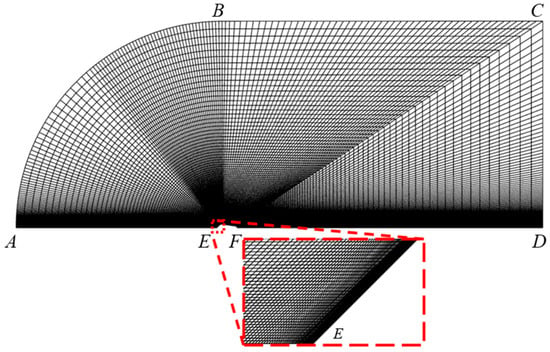
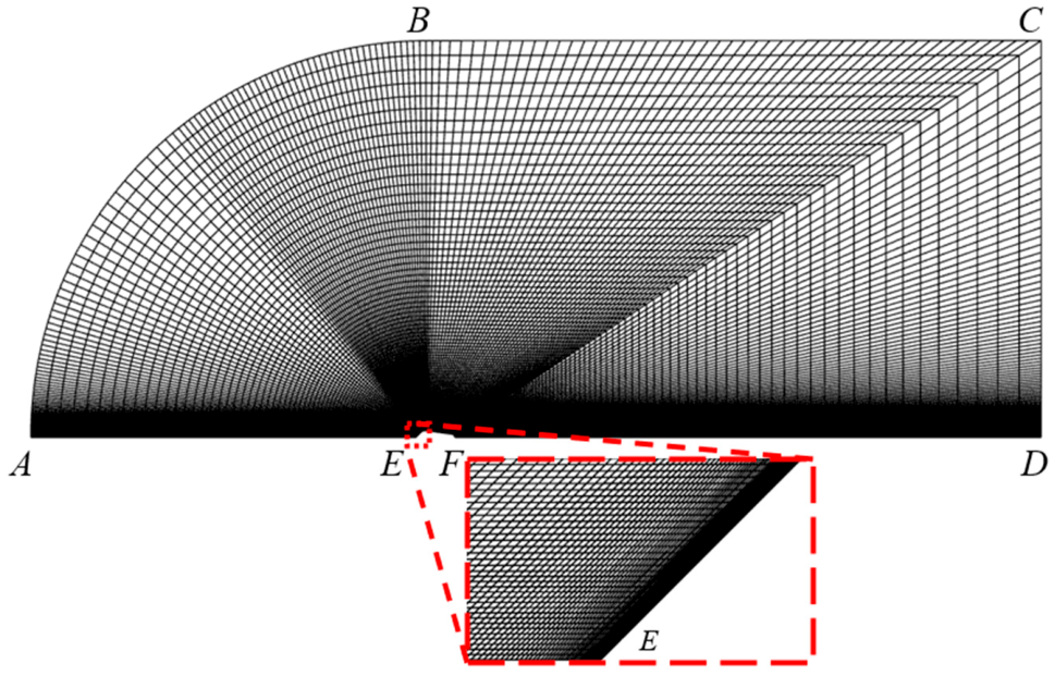
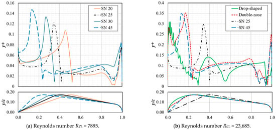
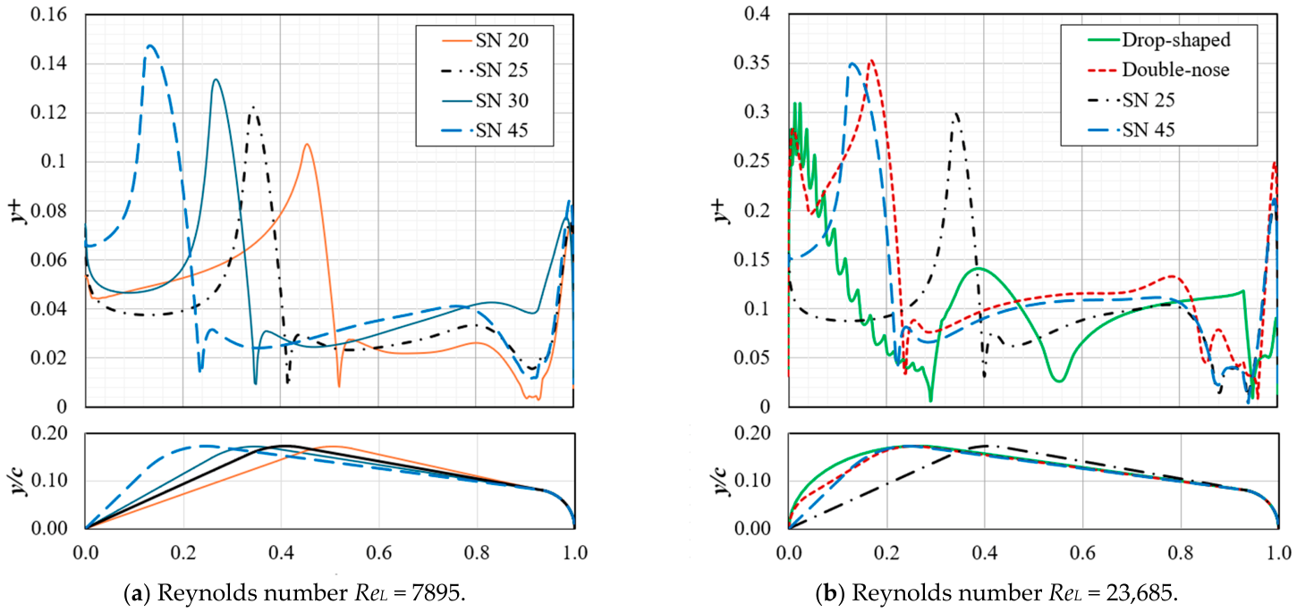
Figure 3 illustrates the typical structured computational mesh with approximately 400 × 200 quadrilateral elements. To ensure that the boundary layer is resolved properly, the first mesh layer height is determined by requiring that the non-dimensional wall height y+ < 1. Table 2 lists the results of the calculation of the first mesh layer height corresponding to the two flow Reynolds number cases considered in this study. Figure 4 shows the surface y+ distribution plots for the select tube shapes at different Reynolds numbers to avoid crowding. In all cases, however, the results indicate that the computational mesh is sufficiently resolved and satisfies the y+ < 1 requirement for the turbulence model considered in this study.
Figure 3.
The structured computational mesh used in the analyses.
Table 2.
The first wall mesh height calculation for y+ = 1.
Figure 4.
The surface y+ distribution plots for the different tube shapes at different flow Reynolds numbers: (a) ReL = 7895, and (b) ReL = 23,685.
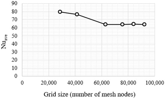
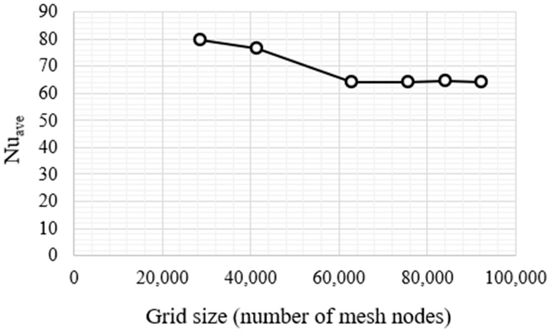
Mesh size adequacy was determined by examining the convergence of results for several different mesh sizes. For this purpose, simulations were performed for a flow velocity of 4 m/s and uniform tube surface heat flux of 2000 W/m2 over the SN 45 tube profile. Figure 5 shows the grid convergence results and suggests the adequacy of using the structured computational mesh with approximately 400 × 200 quadrilateral elements for the analyses.
Figure 5.
The grid convergence results.
To determine the robustness of the numerical technique, numerical simulations were performed at flow velocity increments of ±0.1, ±0.2, and ±0.3 m/s around 4 m/s for a uniform tube surface heat flux of 2000 W/m2 over the SN 25 tube profile. The computed Nusselt numbers show a mean value of 81.44 ± 2.61 with a 95% confidence interval of [79.03, 83.85]. Linear regression analysis reveals a highly significant dependence on flow velocity (p < 0.001, R2 = 0.9999), indicating a strong and reliable monotonic increase. These results confirm the robustness and numerical stability of the computational model, with negligible statistical uncertainty relative to the observed trend.
2.5. Validation Case
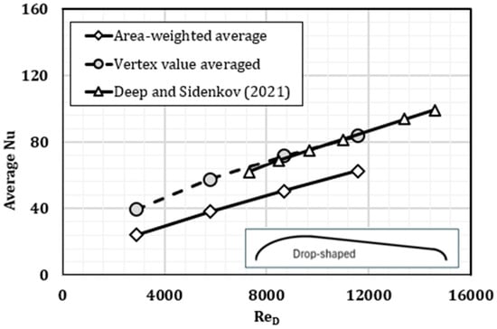
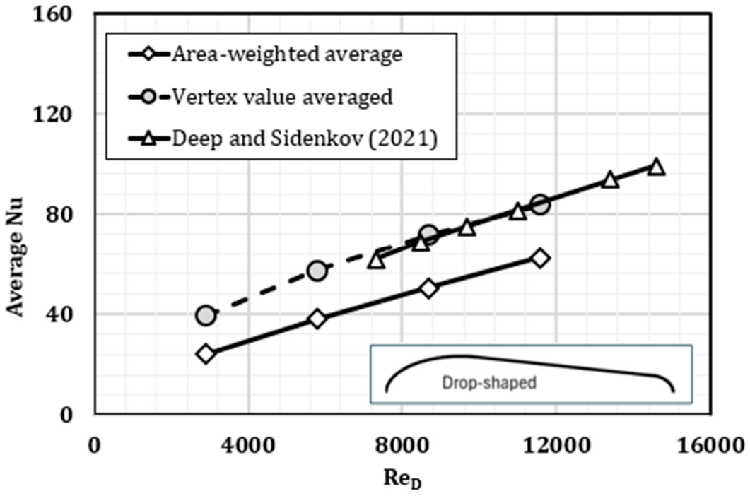
Figure 6 shows a comparison of current simulation results with those predicted by Deep and Sidenkov [8] for the drop-shaped tube cross-section. Deep and Sidenkov [8] calculate the Nusselt number over the entire upper surface of the tube based on the average of the Nusselt number values at each vertex of the tube. As can be seen from the figure, the vertex-value based average results using the current methodology match quite well with the predictions of Deep and Sidenkov [8]. Since the tube has curvature, an uneven vertex spacing is used to capture the surface gradients adequately and, consequently, to obtain a more accurate estimate of the Nusselt number over the entire upper surface. Therefore, in this study, the Nusselt number over the length of the entire upper surface is based on the surface area-weighted average values of the Nusselt numbers values at the vertices. The results for the surface area-weighted average values of the Nusselt numbers are also shown in Figure 6 and suggest that the vertex-averaged results overpredict the results by almost 40%.
Figure 6.
Validation of numerical results for drop-shaped tube cross-section [8].
3. Results and Discussion
3.1. Overview
Numerical simulations were carried out to compare the flow field, flow separation, vorticity and heat transfer characteristics of each tube cross-section shape. The results are used to determine the thermal–hydraulic performance metric [26] for each tube cross-section shape considered in this study in order to determine which tube shape yields the best thermal–hydraulic performance. Similar studies on tube shapes were performed by Deep and Sidenkov [1] in which they considered tube cross-sections with round-nose profiles that included among others the drop-shaped tube cross-section. They [1] found that the drop-shaped tube cross-section yields the best thermal–hydraulic performance amongst other tube cross-sections. The focus of the current study is to compare the thermal–hydraulic performance of the drop-shaped tube cross-section with that of the sharp-nose tube sections to determine whether or not sharp-nose sections yield better thermal–hydraulic performance that the round-nose tube section. Therefore, drop-shaped and double-nose-type tube cross-sections are included in this study for comparison. Details of the simulation results are discussed in the sections that follow.
3.2. Flow Field Characteristics
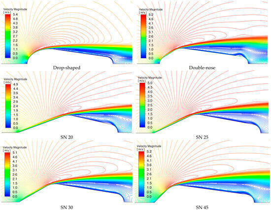
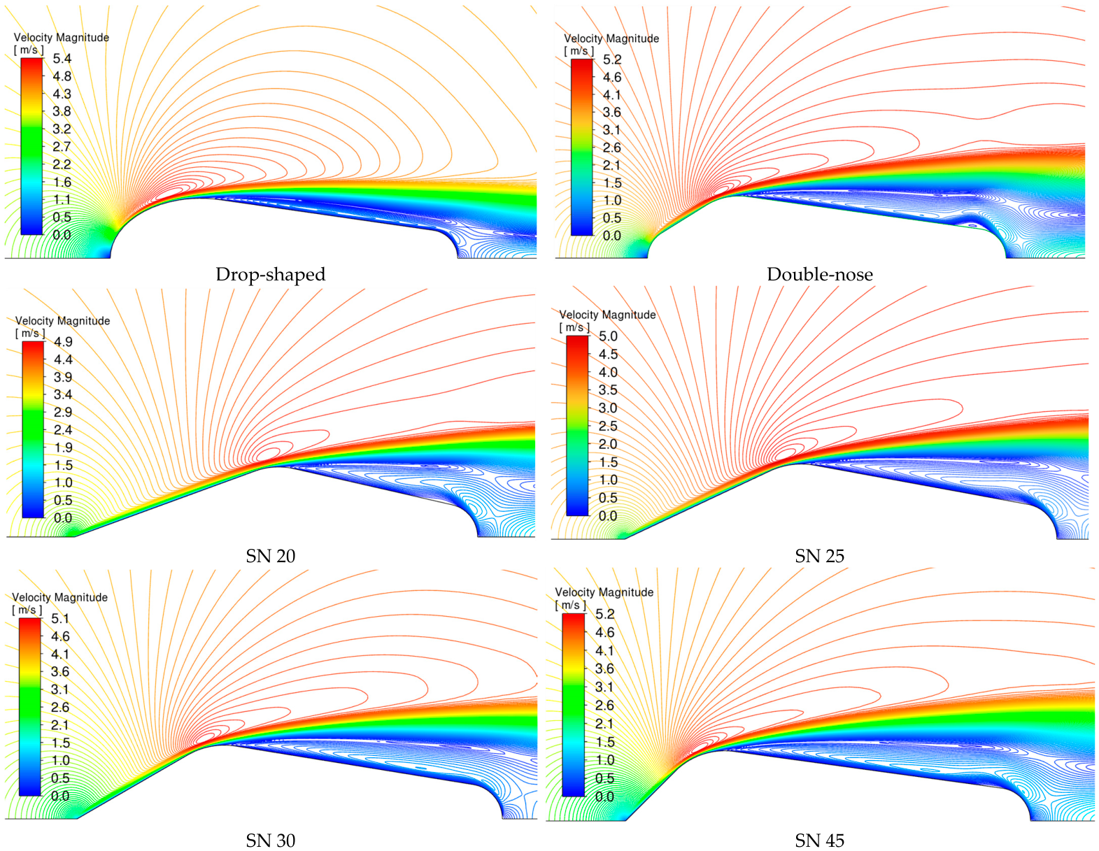
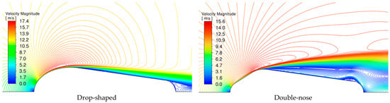
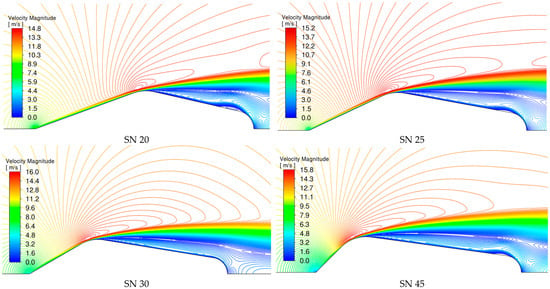
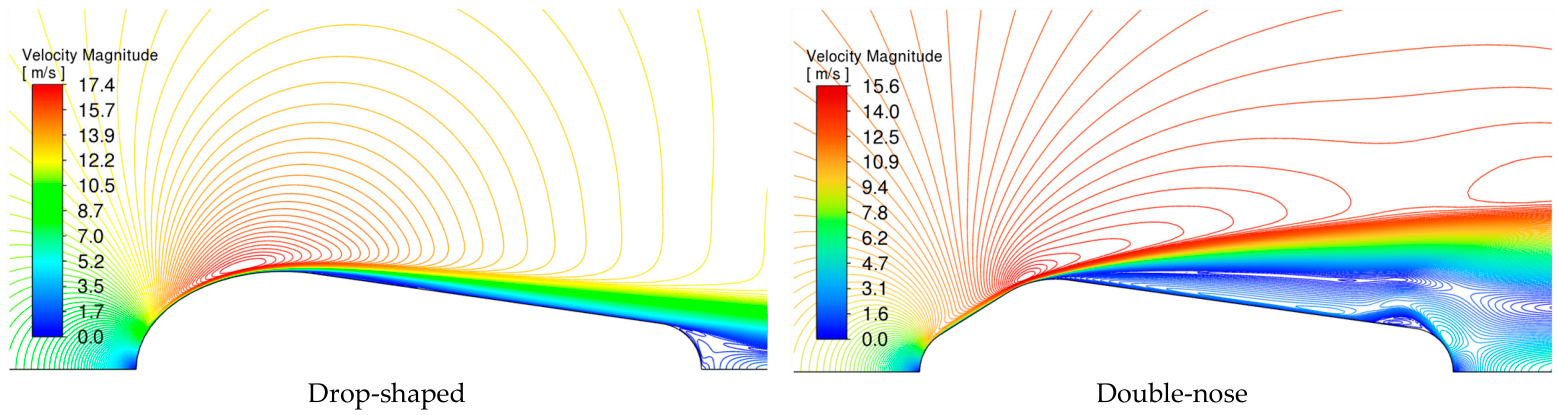
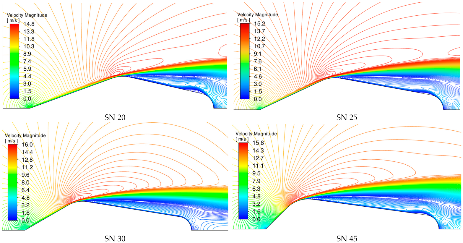
Figure 7 and Figure 8 show contour plots of the velocity magnitude for input flow velocity of 4 m/s and 12 m/s corresponding to flow Reynolds numbers of 7895 and 23,685, respectively, based on the reference length (chord) of the tubes for the six tube shapes shown in Figure 1c. From these plots, it is evident that the more streamlined the cross-section, the less intense the flow separation region marked by blue contour lines.
Figure 7.
Velocity magnitude contours in 4 m/s flow field.
Figure 8.
Velocity magnitude contours in 12 m/s flow field.
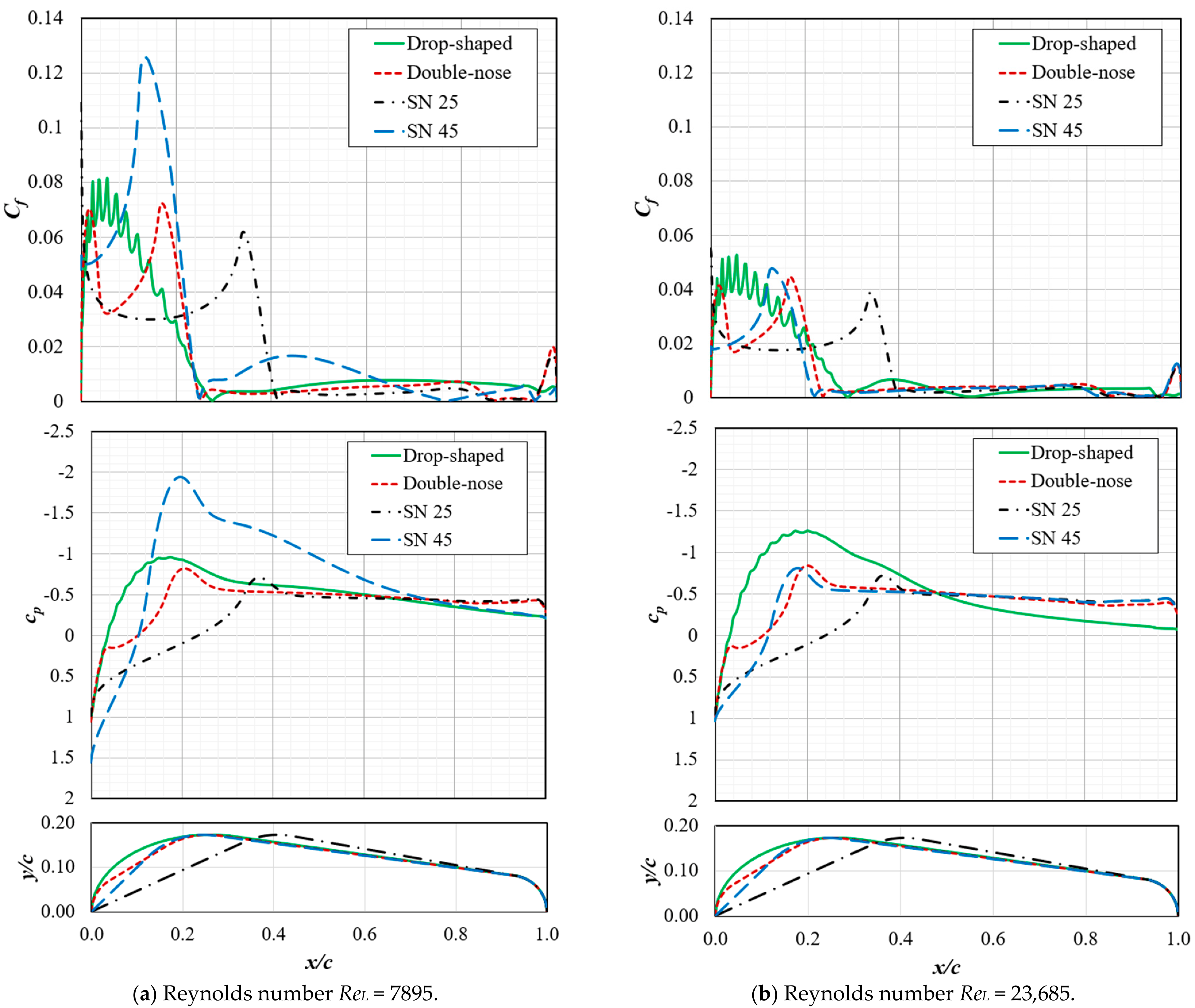
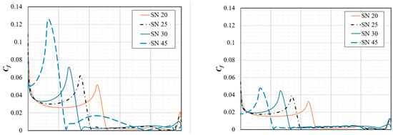
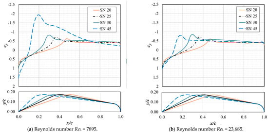
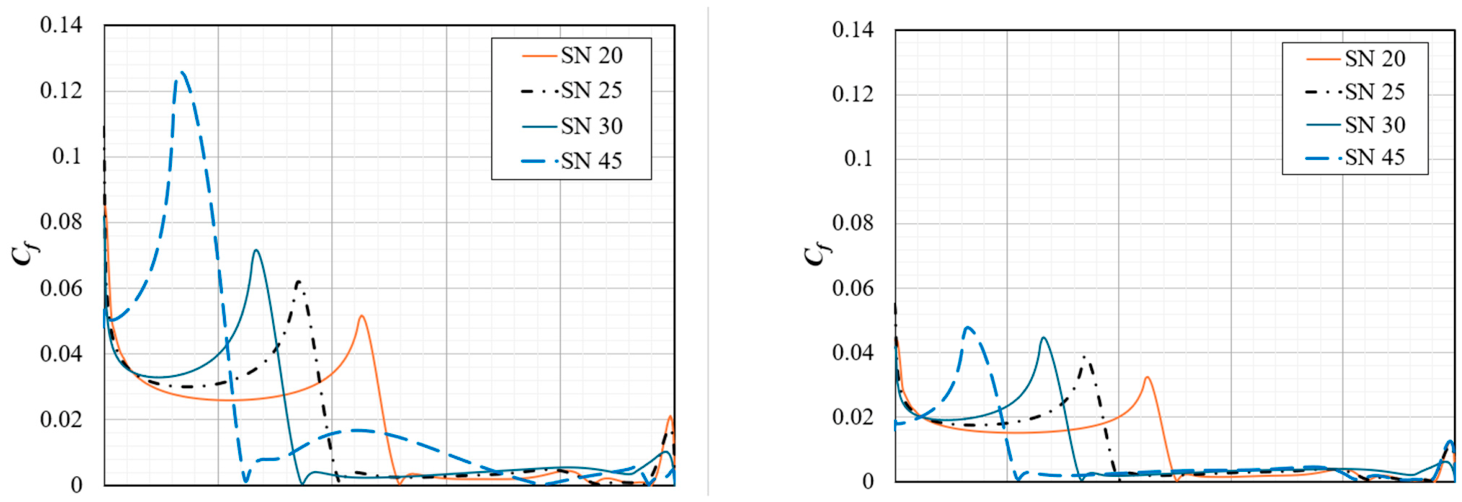
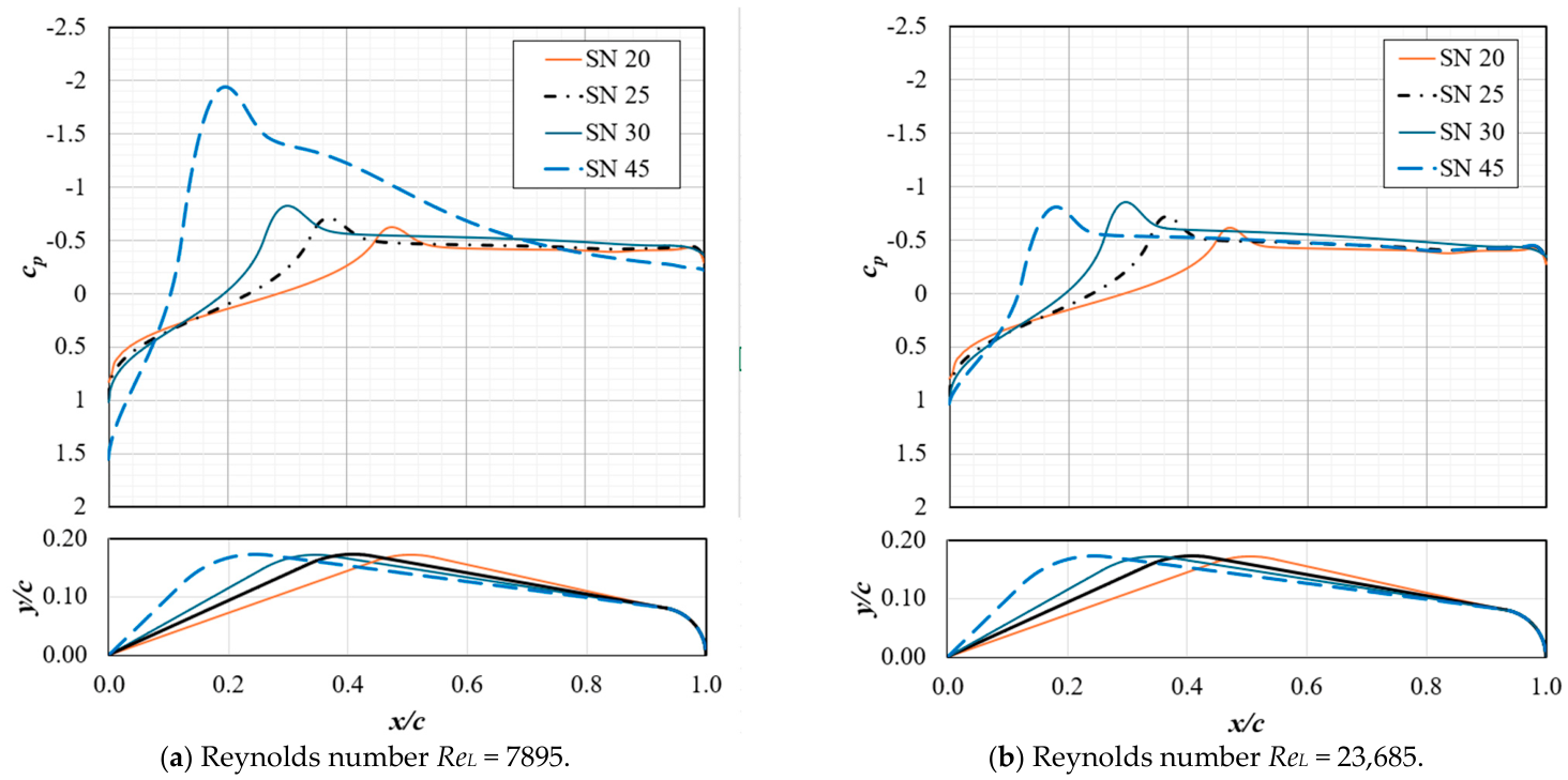
A better understanding of the flow field is revealed by the skin friction Cf and pressure coefficient cp plots shown in Figure 9 and Figure 10. The peaks in both the skin friction Cf and pressure coefficient cp plots are coincident at the maximum thickness location of all the profiles. It is noted here that although the bulk Reynolds numbers correspond to fully turbulent flow, localized flow features such as recirculation zones and near-wall effects may exhibit transitional characteristics which is often the case for surfaces with sudden changes in wall curvature. These transitional characteristics are marked by a sharp drop in the skin friction coefficient as reflected in Figure 9 and Figure 10. These results also indicate that as the nose profile changes from a round to a sharp ramp-type shape and the maximum thickness location moves further downstream, the peaks in both the skin friction Cf and pressure coefficient cp plots are also displaced further downstream and help to delay the transition to turbulence. Hence, the sharp-nose profiles further extend the laminar region over the surface of the tubes. In addition, the same trend is observed when the sharp-nose profiles are compared to each other, i.e., decreasing the nose angle θ from 45 deg to 20 deg corresponding to the tube profiles SN45 and SN20, respectively, as shown in Figure 10, results in the peaks in both the skin friction Cf and pressure coefficient cp plots being displaced further downstream and hence helping to delay transition. This fact is also intuitive since a sharp-nose profile will result in a lower friction drag in a flow as compared to a more blunt nose profile.
Figure 9.
Surface skin friction and pressure coefficient distribution comparison of select geometries at different flow Reynolds numbers: (a) ReL = 7895, and (b) ReL = 23,685.
Figure 10.
Surface skin friction and pressure coefficient distribution comparison of sharp-nose geometries at different flow Reynolds numbers: (a) ReL = 7895, and (b) ReL = 23,685.
3.3. Heat Transfer Characteristics
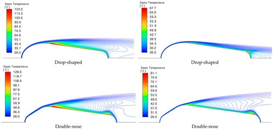
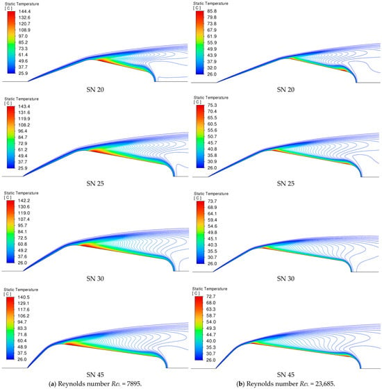
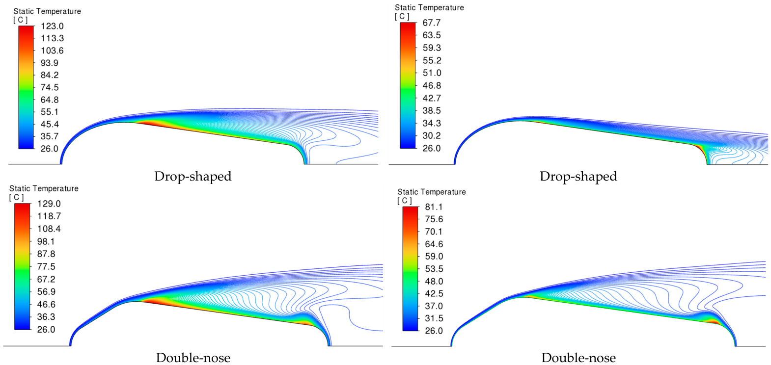
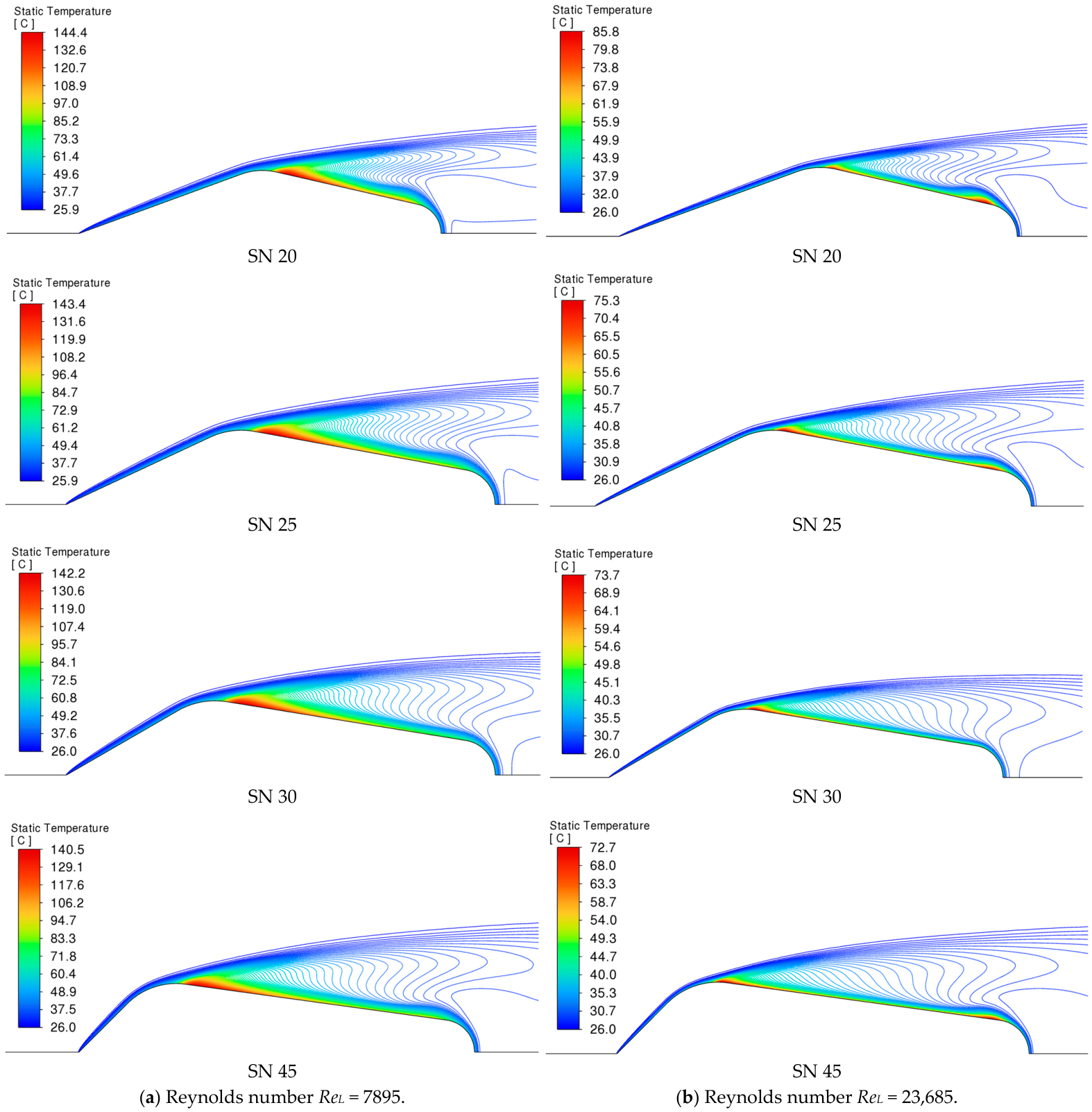
The effect of nose shape on the heat transfer characteristics of the profiles and the static temperature contours for the input flow velocity of 4 m/s and 12 m/s corresponding to flow Reynolds numbers of 7895 and 23,685, respectively, are presented side-by-side in Figure 11a,b. The simulation results indicate that the flow field exhibits higher static temperature levels at lower inlet velocities when the surface profile is maintained at the same prescribed temperature. This behavior is expected, as reduced flow velocities diminish the convective heat transfer capability of the fluid. Consequently, the flow remains in contact with the heated surface for a longer duration, allowing greater thermal energy absorption and limiting the ability of the flow to transport heat away. The weaker convective cooling at lower velocities therefore leads to elevated static temperatures within the boundary layer and the surrounding flow region.
Figure 11.
Comparison of static temperature contours between the two flow fields at different flow Reynolds numbers: (a) ReL = 7895, and (b) ReL = 23,685.
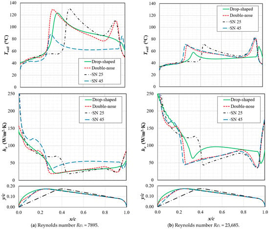
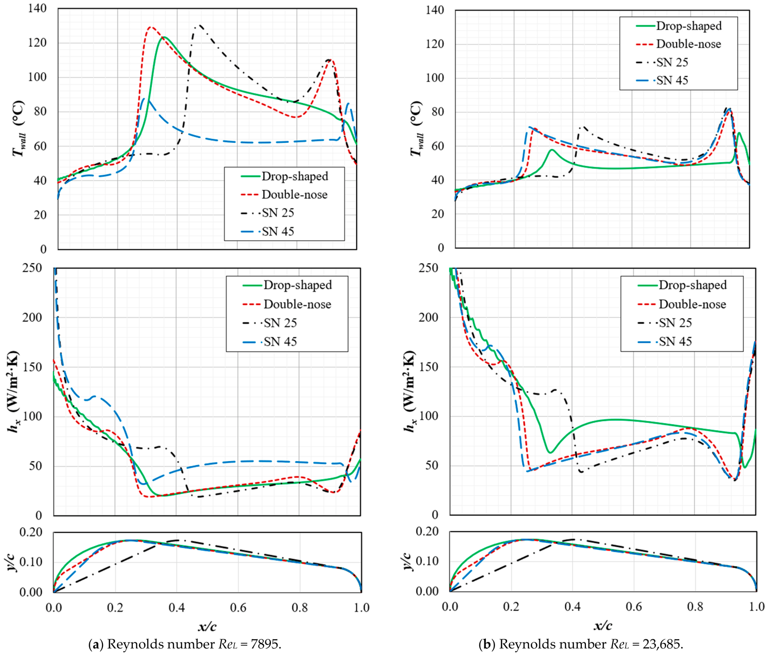
This reduced convective transport also manifests in the surface temperature distribution shown in Figure 12. Specifically, the surface exhibits higher temperature profiles at lower flow velocities, consistent with the reduced cooling capacity of the incoming fluid. Moreover, the results show a pronounced rise in surface temperature downstream of the point of maximum thickness. This sharp increase corresponds to the transition from laminar to turbulent flow, during which enhanced mixing intensifies the transfer of thermal energy from the surface into the fluid, leading to a rapid elevation in surface temperature. Following this region, the temperature profile displays a second significant increase near the trailing edge, where the effects of boundary-layer separation become more pronounced. In this separated flow region, the reduced momentum of the fluid further weakens convective heat removal, allowing additional temperature buildup near the surface. Taken together, these observations highlight the strong coupling between local flow behavior, particularly velocity, transition, and separation, and the resulting heat transfer characteristics of the surface and surrounding flow field. This phenomenon explains the reason behind the decreased heat transfer coefficient where surface temperatures are high and increased heat transfer coefficient when surface temperatures are low.
Figure 12.
Surface heat transfer coefficient and wall temperature distribution comparison at different flow Reynolds numbers: (a) ReL = 7895, and (b) ReL = 23,685.
3.4. Thermal–Hydraulic Performance
The thermal–hydraulic performance metric of a tube with a given profile shape as compared to that of some reference profile shape was proposed by Webb [26] as:
where the friction factor f for the particular tube profile in question is based on the non-dimensional value of the pressure drop across the channel based on the simulation results. In the present study, the thermal–hydraulic performance metric of a tube of a given profile shape as compared to that of the drop-shaped profile, used as the reference in the present study, is defined as
In the above equation, and are the area-weighted average values of the Nusselt number and skin friction coefficient, respectively, obtained from the numerical solution. The area-weighted average values of the Nusselt number and skin friction coefficient are obtained by numerically integrating the local (node) values of the Nusselt number and skin friction coefficient over the entire length L of the upper half of the discretized tube shape using the following relations:
The results for the drop-shaped tube have been chosen as a reference in the present study since a similar study performed by Deep and Sidenkov [8] compared the thermal–hydraulic performance of the tubes with round noses that included circular, elliptical, cam, flat and drop-shaped tubes in which they concluded that the drop-shaped tube yields the best thermal–hydraulic performance amongst all other selected tube shapes. The focus of the present study as stated earlier is to investigate the thermal–hydraulic performance of the tubes with sharp-nose angles as shown in Figure 1b,c. In addition, two round-nose tubes have been included in the present study that include: (a) a drop-shaped tube profile similar to the profile in Ref. [8] for the sake of comparison, and (b) a tube profile with a double (round) nose as an intermediate profile between the round- and sharp-nose profiles.
Table 3 and Table 4 list results of the numerical simulations of flow around eight different tube shapes at flow velocities of 4 m/s and 12 m/s corresponding to flow Reynolds numbers of 7895 and 23,685. These tables compare the key thermal and hydraulic performance parameters for the selected tube shapes. The results indicate that both the double-nose and the sharp-nose profiles with an optimum nose angle achieve between 4% and 25% higher thermal–hydraulic performance than that of the drop-shaped tube profile that showed superior thermal–hydraulic performance amongst the other round-nose tube profiles in the earlier study [1] over the range of flow Reynolds numbers considered in both the present and earlier study. In addition, the optimum nose angle θ = 25° yields the highest thermal–hydraulic performance amongst all the profiles within the range of flow Reynolds numbers considered, in general, and 25.3% higher than that of the drop-shaped tube at Re = 7895, in particular. Furthermore, at a low flow Reynolds number, sharp-nose tubes with nose angles 20° ≥ θ ≥ 45° also outperform the drop-shaped tube’s performance. The results also show that as the nose angle of the tube is increased beyond the optimum value, the thermal–hydraulic performance approaches that of the double-nose-shaped tube. In fact, the double-nose tube profile is very similar to the SN45 profile in that it has a more rounded nose and edges than the SN45 profile, which explains why the two profiles have almost similar thermal–hydraulic performance values. The results suggest that a higher value of the area-skin friction coefficient and the flow separation characteristics are the key behind determining the thermal–hydraulic performance measure, since both result in an increase in the resident time of the flow over the tube surface.
Table 3.
Thermal–hydraulic performance comparison at flow Re = 7895.
Table 4.
Thermal–hydraulic performance comparison at flow Re = 23,685.
4. Conclusions
In this study, the thermal and hydraulic performance of several sharp-nose tube profiles has been investigated through numerical simulations of flow around several sharp-nose tube profiles intended for use in heat exchangers or similar devices. Numerical simulations of flow around eight different tube shapes, including both round- and sharp-nosed profiles with a range of nose angles from 20° to 45°, were performed at flow velocities of 4 m/s and 12 m/s corresponding to flow Reynolds numbers of 7895 and 23,685, respectively. The thermal–hydraulic performance metric is used to compare the performance of the sharp-nose tube profiles with existing studies on round-nose tube profiles. The following main conclusions can be drawn from the present study:
- The results indicate that both the double-nose and sharp-nose profiles with an optimum nose angle achieve between 4% and 25% higher thermal–hydraulic performance than that of the drop-shaped tube profile. The drop-shaped geometry had previously exhibited the highest superior thermal–hydraulic performance amongst the rounded-nose tube profiles in an earlier study [8], and the present improvement is observed consistently across the investigated range of Reynolds numbers.
- The optimum nose angle θ = 25° provides the greatest enhancement in thermal–hydraulic performance within the range of flow Reynolds numbers considered, reaching an improvement of 25.3% relative to the drop-shaped tube at Re = 7895. At a lower flow Reynolds number, sharp-nose tubes with nose angles in the range 20° ≥ θ ≥ 45° also outperform the drop-shaped tube’s performance.
- The findings further indicate that as the nose angle increases beyond the optimum value, the thermal–hydraulic performance of the sharp-nose profile converges toward that of the double-nose tube. This trend is consistent with the geometric similarity between the two profiles: the double-nose tube possesses a more rounded nose and smoother edges, closely resembling the SN45 profile, which explains their nearly identical performance characteristics.
- Overall, the results suggest that the elevated value of the area-weighted average skin friction coefficient and the associated flow separation behavior play a dominant role in governing the thermal–hydraulic performance metric. Both factors contribute to an increased resident time of the fluid over the tube surface, thereby enhancing heat transfer effectiveness.
A logical extension of this work is to evaluate the performance of these tube geometries within a heat exchanger configuration, where multiple tubes are arranged in parallel and staggered layouts. Such an investigation is essential for identifying the arrangement that delivers the greatest enhancement in overall heat transfer effectiveness.
Author Contributions
Conceptualization, A.O.E.; Methodology, F.S. and A.O.E.; Software, F.S. and A.O.E.; Validation, F.S. and A.K.A.E.; Formal analysis, F.S.; Investigation, A.O.E. and A.K.A.E.; Data curation, A.K.A.E.; Writing—original draft, F.S.; Writing—review & editing, A.O.E. and A.K.A.E. All authors have read and agreed to the published version of the manuscript.
Funding
This research received no external funding.
Data Availability Statement
The original contributions presented in the study are included in the article, further inquiries can be directed to the corresponding author.
Acknowledgments
The authors would like to acknowledge the support of Imam Abdulrahman bin Faisal University in accomplishing the present study.
Conflicts of Interest
The authors declare no conflict of interest.
Nomenclature
| Symbol | Description | Unit |
| Skin friction coefficient () | – | |
| cp | Pressure coefficient | – |
| Deq | Equivalent diameter | m |
| Dh | Hydraulic diameter | m |
| hx | Heat transfer coefficient | W/(m2·K) |
| I | Turbulence intensity ( | % |
| k | Thermal conductivity | W/(m·K) |
| L | Characteristic length | m |
| Nu | Nusselt number | – |
| p | Air pressure | Pa |
| Reynolds number ( | – | |
| T | Air temperature | K |
| Friction velocity | m/s | |
| V | Free-stream velocity | m/s |
| y | First cell height () | m |
| y+ | Non-dimensional wall height | – |
| α | Angle of attack | deg |
| η | Thermal–hydraulic performance metric | – |
| θ | Nose angle | deg |
| μ | Dynamic viscosity | Pa·s |
| ρ | Air density | kg/m3 |
| ν | Kinematic viscosity | m2/s |
| Wall shear stress | Pa | |
| Subscript | ||
| i | Column number in tube array | |
| j | Row number in tube array | |
References
- Li, Y.; Fu, Y.; Zhang, J.; Zhang, J.; Xu, J.; Ma, S.; Sundén, B.; Xie, G. Investigation of heat transfer performance and enhancement mechanisms of supercritical carbon dioxide in PCHE with fractal airfoil fins. Case Stud. Therm. Eng. 2024, 60, 104802. [Google Scholar] [CrossRef] [Scilit]
- Kumar, S.; Das, R.K.; Kulkarni, K.; Alam, T.; Eldin, S.M. Designing of low-cost solar air heater equipped with roughness of streamlined cross-section. Case Stud. Therm. Eng. 2023, 45, 102915. [Google Scholar] [CrossRef] [Scilit]
- Deeb, R. Enhancing heat exchanger performance through hybrid angle of attack control for drop-shaped tubes. Phys. Fluids 2023, 35, 085122. [Google Scholar] [CrossRef] [Scilit]
- Deeb, R.; Sidenkov, D.V. Numerical simulation of the flow past the three-row staggered drop-shaped tube bundle at different angles of attack. In Proceedings of the IEEE International Conference Inforino 2022; IEEE: Moscow, Russia, 2022. [Google Scholar] [CrossRef] [Scilit]
- Deeb, R.; Sidenkov, D.V. Evaluation of turbulence models for flow and heat transfer of drop-shaped tubes. In Proceedings of the VI International Conference on Information Technologies in Engineering Education (Inforino), Moscow, Russia, 12–15 April 2022; pp. 1–5. [Google Scholar] [CrossRef] [Scilit]
- Deeb, R. Experimental and numerical investigation of the effect of angle of attack on air flow characteristics around drop-shaped tubes. Phys. Fluids 2021, 33, 065110. [Google Scholar] [CrossRef] [Scilit]
- Deeb, R.; Sidenkov, D.V. Numerical analysis of heat transfer and fluid flow around circular and non-circular tubes. J. Phys. Conf. Ser. 2021, 2088, 012008. [Google Scholar] [CrossRef] [Scilit]
- Deeb, R.; Sidenkov, D.V. The effects of the axis ratio on the flow and heat transfer characteristics around a drop-shaped tube. J. Phys. Conf. Ser. 2021, 2057, 012001. [Google Scholar] [CrossRef] [Scilit]
- Thejaraju, R.; Girisha, K.B.; Manjunath, S.H.; Dayananda, B.S. Experimental investigation of turbulent flow behavior in an air-to-air double pipe heat exchanger using novel para winglet tape. Case Stud. Therm. Eng. 2020, 22, 100791. [Google Scholar] [CrossRef] [Scilit]
- Ma, H.; Duan, Z. Similarities of flow and heat transfer around a circular cylinder. Symmetry 2020, 12, 658. [Google Scholar] [CrossRef] [Scilit]
- Deeb, R.; Sidenkov, D.V. Numerical investigation of heat transfer and friction factor characteristics for staggered double drop-shaped tube bundles in crossflow. J. Phys. Conf. Ser. 2020, 1675, 012017. [Google Scholar] [CrossRef] [Scilit]
- Gururatana, S.; Skullong, S. Experimental investigation of heat transfer in a tube heat exchanger with airfoil-shaped insert. Case Stud. Therm. Eng. 2019, 14, 100462. [Google Scholar] [CrossRef] [Scilit]
- Ahmed, S.A.; Ibrahiem, E.Z.; Mesalhy, O.M.; Abdellatief, M.A. Effect of attack and cone angles on air flow characteristics for staggered wing-shaped tubes bundle. Heat Mass Transf. 2015, 51, 1001–1016. [Google Scholar] [CrossRef] [Scilit]
- Ahmed, S.A.; Ibrahiem, E.Z.; Mesalhy, O.M.; Abdellatief, M.A. Heat transfer characteristics of staggered wing-shaped tube bundles at different angles of attack. Heat Mass Transf. 2014, 50, 1091–1102. [Google Scholar] [CrossRef] [Scilit]
- Murthy, M.S.R.; Gupta, A.V.S.S.K.S. Experimental investigation of flow and heat transfer characteristics over a NACA0018 airfoil for different height ratios. Heat Mass Transf. 2014, 50, 923–932. [Google Scholar] [CrossRef] [Scilit]
- Deeb, R.; Sidenkov, D.V. Numerical investigation of heat transfer and aerodynamics of single drop-shaped tubes. Vestn. Mezhdunarodnoi Akad. Kholoda 2020, 3, 91–99. [Google Scholar] [CrossRef] [Scilit]
- Deeb, R.; Sidenkov, D.V. Numerical simulation of the heat transfer of staggered drop-shaped tubes bundle. J. Phys. Conf. Ser. 2019, 1359, 012135. [Google Scholar] [CrossRef] [Scilit]
- Deeb, R. Correlations and numerical analysis of thermal-hydraulic performance of staggered mixed tube bundle composed of circular and drop-shaped tubes. Int. J. Heat Mass Transf. 2022, 199, 123487. [Google Scholar] [CrossRef] [Scilit]
- Deeb, R. Numerical analysis of the effect of longitudinal and transverse pitch ratio on the flow and heat transfer of staggered drop-shaped tubes bundle. Int. J. Heat Mass Transf. 2022, 183, 122123. [Google Scholar] [CrossRef] [Scilit]
- Matsuda, V.A.; Martins, I.T.; Moreira, D.C.; Cabezas-Gómez, L.; Filho, E.P.B. A modified enthalpic lattice Boltzmann method for simulating conjugate heat transfer problems in non-homogeneous media. Inventions 2024, 9, 57. [Google Scholar] [CrossRef] [Scilit]
- Li, C.; Qu, X.; Li, T. A hybrid immersed boundary–lattice Boltzmann method for flow and heat transfer within a fluid heat exchanger. Phys. Fluids 2025, 37, 037171. [Google Scholar] [CrossRef] [Scilit]
- Mukutmoni, D.; Shock, R.; Li, H.; Wanderer, J.; Gopalaswamy, N.; Miao, L. Simulation of conjugate heat transfer using the lattice Boltzmann method. In Proceedings of the WCX SAE World Congress Experience, Detroit, MI, USA, 14 April 2026. [Google Scholar] [CrossRef] [Scilit]
- Zhao, Y.; Liu, X.; Chen, Z.; Wang, L. Alternative multiple-relaxation-time lattice Boltzmann method for simulating conjugate heat transfer. Phys. Rev. E 2025, 111, 055304. [Google Scholar] [CrossRef] [Scilit] [PubMed]
- Landl, M.; Prieler, R.; Monaco, E.; Hochenauer, C. Numerical investigation of conjugate heat transfer and natural convection using the lattice-Boltzmann method for realistic thermophysical properties. Fluids 2023, 8, 144. [Google Scholar] [CrossRef] [Scilit]
- Zhou, Y.; De Rosis, A.; Revell, A. Coupling finite volume–lattice Boltzmann methods for advanced heat transfer simulations. Eng. Comput. 2026, 42, 56. [Google Scholar] [CrossRef] [Scilit] [PubMed]
- Webb, R.L. Performance evaluation criteria for use of enhanced heat transfer surfaces in heat exchanger design. Int. J. Heat Mass Transf. 1981, 24, 715–726. [Google Scholar] [CrossRef] [Scilit]

Disclaimer/Publisher’s Note: The statements, opinions and data contained in all publications are solely those of the individual author(s) and contributor(s) and not of MDPI and/or the editor(s). MDPI and/or the editor(s) disclaim responsibility for any injury to people or property resulting from any ideas, methods, instructions or products referred to in the content. |
© 2026 by the authors. Licensee MDPI, Basel, Switzerland. This article is an open access article distributed under the terms and conditions of the Creative Commons Attribution (CC BY) license.