


Abstract
This paper presents an adaptive and flexible Automatic Generation Control (AGC) scheme designed for power system splitting and reconnection. The proposed AGC remains fully operational throughout grid splitting, maintaining independent control over each separated area and supporting the transition toward reconnection through improved Area Control Error (ACE) and frequency recovery. It detects splitting by analyzing the frequency coherency of generating units and then autonomously configures the operational mode of each area in accordance with ENTSO-E rules. It applies an adaptive PI controller whose integral gain () is dynamically selected from a lookup table developed through offline tuning and correlation analysis to accommodate various grid configurations. Additionally, during splitting, the AGC performs adaptive reserve activation in each area, rather than relying on predetermined market-based reserve activation. The proposed AGC scheme is validated within a software-in-the-loop (SIL) environment using a representative model of the Turkish Transmission System. The results show that the proposed AGC maintains continuous and adaptive load frequency control (LFC) and improves reserve deployment in both interconnected and isolated operating modes of multi-area power systems. The proposed scheme reduces ACE recovery time by up to 87%, mitigates overshoots, and accelerates frequency recovery. These results demonstrate the scheme’s ability to maintain continuous AGC operation, improve frequency and ACE recovery, and satisfy the adopted ENTSO-E operational performance criteria under splitting conditions.
1. Introduction
The increasing penetration of renewable energy sources and the rising complexity of modern power systems present significant operational challenges for Transmission System Operators (TSOs). As renewable integration grows, the variability and low inertia of these sources complicate frequency stability, especially during disturbances [1]. In this context, AGC is critical for maintaining the supply–demand balance and regulating frequency. Its importance is heightened in power system splitting events, where the grid divides into small and independent control areas [2]. Such fragmentation can result from faults, overloads, or extreme operating conditions. In these cases, AGC must autonomously manage each area. However, conventional AGC approaches often lack the responsiveness needed for grid splitting scenarios [3], underscoring the need for adaptive and flexible control strategies to ensure reliable system operation.
Operating one of the world’s largest synchronous areas, ENTSO-E has recently faced growing challenges in managing system separations and frequency stability. In its 2021 Annual Report [4], ENTSO-E highlighted the impact of reduced inertia on frequency stability within the synchronous area due to large-scale integration of renewables. Additionally, ENTSO-E’s 2023 report on frequency stability in long-term scenarios emphasizes the progressive decline in resilience against system splits, underscoring the need for mitigation measures to address these challenges [5]. High-impact incidents, including the Continental Europe split on 8 January 2021 [6,7], the Iberian Peninsula separation in July 2021 [8], and the southeastern Europe split in June 2024 [9], illustrate the operational complexity and control limitations during such events. Turkey’s nationwide blackout on 31 March 2015 also demonstrates the risks posed by system splits, where extreme conditions or failures can escalate into widespread outages [10,11]. In response, ENTSO-E has introduced comprehensive policies [12] to strengthen LFC and coordination among TSOs.
Existing AGC strategies proposed in the literature have primarily focused on enhancing LFC performance under normal operating conditions or conventional disturbances, rather than explicitly addressing power system splitting and reconnection scenarios [1,13,14,15]. Traditional AGC implementations are typically based on proportional–integral (PI) or proportional–integral–derivative (PID) controllers, with performance improvements achieved through techniques such as fuzzy logic, artificial neural networks (ANNs), and metaheuristic optimization. For example, a cascade PID controller with an integrated filter (PIDF) was introduced in [16], while adaptive PID-based AGC approaches have also been proposed to improve control performance under varying operating conditions and load disturbances [17]. Bevrani et al. developed a Bayesian network-based multi-agent scheme for frequency stability in wind-integrated systems [18]. Other approaches include fuzzy segment-based control with PDCI and adaptive filters applied in the Southwest China Grid [19], and hybrid PSO–MSCA-based PID–FPID strategies designed for systems with electric vehicle aggregators [20]. In addition, various fuzzy logic controllers, ANN-based methods, and optimized fuzzy PI-based control schemes have been proposed to address nonlinear dynamics and improve AGC/LFC responsiveness [21,22].
More recently, advanced adaptive and predictive control techniques have been explored to cope with increasing system complexity. Li and Chen proposed a deep forest network-based AGC that combines PI and DFT logic for real-time optimization [23], while recent multi-agent reinforcement learning-based AGC schemes have been introduced to improve coordination and control performance in interconnected power systems [24]. Model predictive control (MPC) approaches have also been widely investigated due to their ability to explicitly consider system constraints and multivariable dynamics [25,26,27,28]. However, implementing such adaptive control techniques in real-world AGC applications presents significant practical challenges related to computational burden, online optimization requirements, model dependency, data training needs, and stability assurance. These challenges have been highlighted by Bhagat et al., who emphasize the trade-off between control complexity and operational reliability in practical deployments [29], and by Babu et al., who stress the difficulty of mitigating transient responses while maintaining robust control performance [30].
As a consequence, despite the extensive body of AGC research, the literature reveals a clear operational gap regarding AGC schemes that can remain continuously active and effective during power system splitting and subsequent reconnection. Most existing methods either assume intact network topologies or do not explicitly address the need for autonomous area management and uninterrupted control during separation events. To address this gap, this study proposes a novel AGC scheme capable of continuous operation under system splitting conditions. Rather than relying on computationally intensive data-driven or model-based predictive control frameworks that may involve online optimization, model evaluation, or data training, the proposed method employs a practical PI-based control structure with adaptive selected from a lookup table constructed through iterative offline tuning and supported by correlation analysis. This design enables rapid and deterministic gain selection upon confirmation of a splitting event with minimal computational overhead. In addition, the proposed AGC integrates an optimization-based reserve activation strategy to dynamically adjust automatic frequency restoration reserves (aFRRs), thereby enhancing post-disturbance recovery performance.
The basic architecture of the proposed AGC framework, including splitting detection and independent control-loop management, was initially presented in [31]. The present study extends this preliminary framework in two main methodological directions. First, an adaptive selection mechanism is developed, in which a lookup table constructed through iterative offline tuning and supported by correlation analysis enables context-aware gain selection through table indexing and bilinear interpolation. Second, a Sequential Least Squares Programming (SLSQP)-based reserve activation strategy is incorporated into the proposed framework to update the allocation of aFRR among generating units within each separated area, subject to reserve-capacity, ramp-rate, and activation-interval constraints. These two mechanisms are combined within the continuous AGC operation framework and evaluated under splitting and merging scenarios using a representative model of the Turkish transmission system in the software-in-the-loop (SIL) environment. Accordingly, the novelty of this study lies in the integrated use of adaptive gain selection and constrained reserve activation to maintain continuous AGC operation during network splitting and reconnection.
The remainder of this paper is organized as follows. Section 2 presents the proposed AGC methodology, including the control scheme and the adaptive control approach. Section 3 describes the test system and simulation scenarios. Section 4 presents and discusses the simulation results, and Section 5 concludes the paper.
2. Methodology
2.1. The AGC Control Scheme
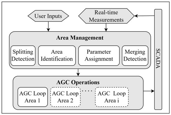
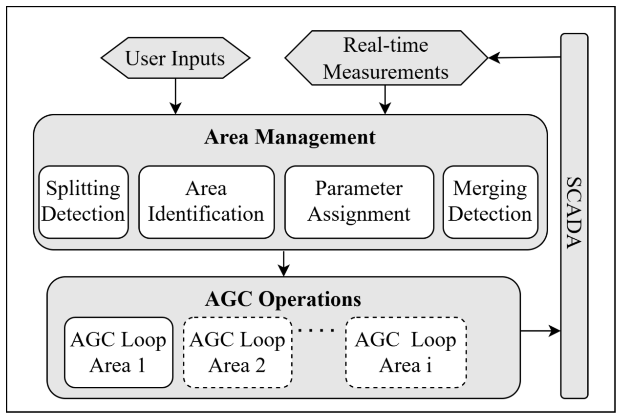
Building on the basic architecture introduced in [31], the extended multi-area AGC scheme comprises two main stages: Area Management and AGC operation, as shown in Figure 1. The Area Management stage processes user inputs and real-time measurements, detects network splitting and merging conditions, identifies the resulting control areas, and reconfigures the AGC into independent control loops when required. The AGC operation stage regulates system frequency and maintains tie-line power exchanges at their scheduled values by adjusting generator outputs within each control area [32]. When a split is detected, the system calculates the Area Control Error (ACE) separately for each resulting area using updated area-specific control parameters, thereby enabling independent frequency and tie-line power control.
Figure 1.
The proposed AGC scheme. Hexagonal blocks represent input data, whereas rounded rectangles represent processing stages and functions. Grey-filled blocks indicate the main processing stages, while white-filled blocks indicate individual functions. Solid outlines define the primary AGC structure, and dotted outlines denote additional control loops dynamically created for separated areas.
As illustrated in Figure 1, the Area Management stage processes both user inputs and real-time SCADA measurements to detect and manage system splitting/merging. It comprises four key functions: Splitting detection, area identification, parameter assignment, and merging detection. Splitting detection monitors frequency deviations among generating units and flags separation when the deviation exceeds a predefined threshold for a sustained duration. While ENTSO-E guidelines consider deviations above 0.2 Hz indicative of splitting and below 0.1 Hz sufficient for merging [6], this study applies stricter thresholds of Hz and Hz, respectively, to construct controlled validation cases on the dynamic model of the Turkish System in the SIL environment. These thresholds are configurable parameters of the proposed detection algorithm rather than universal settings; the stricter values used here enable controlled SIL validation and earlier AGC reconfiguration in the representative Turkish dynamic model. In real applications, the thresholds should be calibrated according to measurement quality, topology confirmation, protection settings, and operator policy; the ENTSO-E values may serve as reference values without limiting the applicability of the proposed framework.
Since AGC operates as a secondary frequency control mechanism, the proposed scheme is intended to act after the immediate transient response following a splitting event. Therefore, a two-cycle (8 s) confirmation period is applied to ensure that the separation is persistent and that the system remains operational following the initial transient dynamics. This duration corresponds to two consecutive AGC control cycles under the default 4 s cycle used in the simulations. It acts as a practical persistence check by requiring the detected frequency incoherency to remain present over two independent measurement updates, thereby reducing false triggering due to single-cycle measurement errors or short transient oscillations. Accordingly, the selected value should be interpreted as a practical validation setting rather than an analytically optimized confirmation time. Once a split is confirmed, unavailable units are excluded and the remaining generators are grouped according to their frequency coherency. The number of separated AGC areas is therefore not fixed in advance, but is determined by the number of coherent generator groups identified after the splitting event. Generating units with similar post-splitting frequency responses are assigned to the same control area, whereas groups exhibiting distinguishable frequency behavior are assigned to separate AGC areas. In the simulation scenarios considered in this study, the detected splitting events result in two AGC areas, denoted as Area-1 and Area-2. The area-specific parameters such as bias factors, reserve capacities, and topology status are then initialized based on whether the area is externally connected or islanded. Merging detection subsequently monitors reconnection conditions and issues a merge signal upon user (i.e., TSO) confirmation; the Hz value therefore defines a merge-eligibility criterion, while the residual realized at the operator-confirmed merge instant may be larger in some cases. After completing the Area Management functions, the AGC scheme activates independent control loops for each area, regulating frequency and tie-line flows based on their respective characteristics.
2.2. The Adaptive Control and Reserve Activation Strategy
This study proposes a systematic methodology for implementing adaptive AGC control. First, representative splitting scenarios are defined based on potential split conditions and examined under varying ACE levels. For each case, effective values are determined using a heuristic trial-and-error method, a common approach in large-scale systems where detailed dynamic modeling is impractical [33]. System parameters potentially correlated with are recorded for each split scenario. A correlation analysis is then performed using ACE and grid parameters, and the most influential and applicable parameter is selected to construct a lookup table. The lookup table is then filled with effective values mapped to corresponding ACE values and grid parameters. This table maps values to ACE and the selected system parameter. During AGC operation, when a split occurs, the corresponding is retrieved from the table considering the current system conditions at the beginning of splitting. If an exact match is unavailable, bilinear interpolation is used to calculate the gain.
To identify the network parameters that have the strongest influence on values, a Pearson correlation matrix is computed [34]. Pearson correlation is selected for its simplicity and effectiveness in identifying relationships between and system parameters. The correlation is determined as in (1).
where is the correlation coefficient between and the network parameter X, represents the covariance between the effective values and X, and and are the standard deviations of and X, respectively. In this study, X denotes one of the candidate network parameters evaluated in the correlation analysis, namely total load, frequency restoration reserve, total inertia contribution , or average inertia . For each area and ACE level, the covariance is calculated as the sample covariance over the representative splitting scenarios by averaging the product of the deviations in and X from their respective sample means. Each observation corresponds to one splitting scenario, where is the effective gain tuned for that scenario and X is the corresponding parameter value. These calculations are repeated separately for each candidate parameter, and total inertia contribution is selected as the common lookup table input to provide a unified and practically measurable basis for adaptive gain selection.
Table 1 presents the Pearson correlation coefficients between values and key network parameters (total load, total aFRR, total inertia contribution (), and inertia ) for various ACE levels. These values reflect the strength of the linear relationship between and each parameter. The correlation matrix indicates a strong negative correlation between and , particularly in Area-1, which remains connected to the ENTSO-E network. In Area-2, which operates in island mode, inertia shows a slightly stronger correlation with ; however, still exhibits a strong and consistent relationship with . Since is physically meaningful and can be calculated from real-time operating data, it was selected as the common scheduling parameter for both interconnected and islanded areas. This choice simplifies practical implementation by avoiding separate area-specific gain-scheduling structures. Accordingly, the proposed lookup table uses total inertia contribution and initial ACE to determine following system splitting, as presented in Table 2.
Table 1.
Pearson correlation coefficients between the effective values and candidate network parameters for various ACE levels.
Table 2.
Lookup table for the effective as a function of total inertia contribution () and ACE.
The proposed AGC algorithm dynamically determines using the lookup table shown in Table 2. For each area (Area-1 and Area-2), the table contains effective values corresponding to typical combinations of total inertia contribution and ACE. The algorithm retrieves the matching entry or, when values fall between table points, applies bilinear interpolation [35] to estimate an interpolated effective . This adaptive approach enables the AGC to accommodate varying operating conditions and splitting configurations through a lookup table-based gain scheduling mechanism supported by correlation analysis, while maintaining computationally efficient real-time implementation through table indexing and bilinear interpolation.
The effective values used in the lookup table were obtained through an offline iterative trial-and-error procedure under representative operating conditions. For each ACE level and splitting scenario, the tuning process was initiated using a predefined reference value. The gain was incrementally adjusted according to the observed ACE response following repeated disturbance events. It was reduced when excessive overshoot or oscillatory behavior was observed and increased when the recovery response remained slow without exhibiting such behavior. As the tuning process converged, the adjustment step size was reduced to enable finer tuning. The evaluation criteria included the avoidance of sustained oscillations, excessive overshoot, and violations of the adopted ACE performance thresholds while maintaining acceptable settling times. Once an value satisfying these criteria was identified, it was stored in the lookup table and reused during real-time operation. Since this procedure is performed offline, the trial-and-error process does not impose any computational burden during real-time AGC execution. The selected values are therefore characterized as effective rather than globally optimal.
The heuristic tuning procedure described above was adopted instead of classical PI/PID tuning rules based on step responses. Applying these rules generally requires a representative linearized process model and, for systems of high order, an appropriate reduced-order approximation [36]. Following network splitting, the dynamics of each resulting control area depend on the network topology and operating point. Consistent application of these rules would therefore require separate model derivation, reduction, and validation for each representative splitting configuration and operating condition. Such an extensive tuning study was considered beyond the scope of the present work.
This study also introduces an improved reserve activation strategy tailored to grid-splitting conditions. Since reserve activation under ramp-rate, capacity, and activation-interval constraints can be formulated as a constrained optimization problem, optimization-based formulations previously used in control applications provide a relevant methodological background [37]. In the proposed scheme, the SLSQP method is used to maximize the area under the production curve while satisfying the operational constraints of each control loop. The resulting optimization generates a dynamic and feasible reserve schedule that supports real-time AGC operation in each separated area. This strategy is designed to improve LFC performance during network splitting. The mathematical formulation is given in (2)–(5).
where is the total production from AGC units as a function of time, is the initial time, and is the final time. and are the minimum and maximum power outputs for unit i, respectively. is the ramp rate limit for unit i. represents the time of the activation for unit i, and is the minimum time interval between reserve activations.
The SLSQP-based reserve activation strategy is implemented as an online optimization layer after a confirmed splitting event. In each AGC control cycle, the optimization is solved separately for each separated area using the current upward and downward aFRR capacities, unit operating points, and ramp rate capabilities obtained from the reserve program and real-time SCADA measurements. The resulting reserve schedule, determined subject to reserve capacity, ramp rate, and activation interval constraints, is subsequently used by the allocation logic within the AGC operation stage to distribute the area control signal among the participating generating units, after which unit setpoints are dispatched through the AGC/SCADA interface. This online reserve allocation is distinct from the adaptive selection mechanism, which requires only lookup table indexing and bilinear interpolation and does not involve online optimization. The implemented SLSQP problem has a limited decision space, and its execution remained compatible with the 4 s AGC control cycle in the SIL environment. Throughout the SIL tests, the complete scheme exchanged data with the dynamic model through the OPC interface.
3. Simulation Environment and Scenarios
3.1. The Simulation and Test Environment
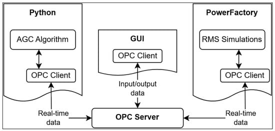
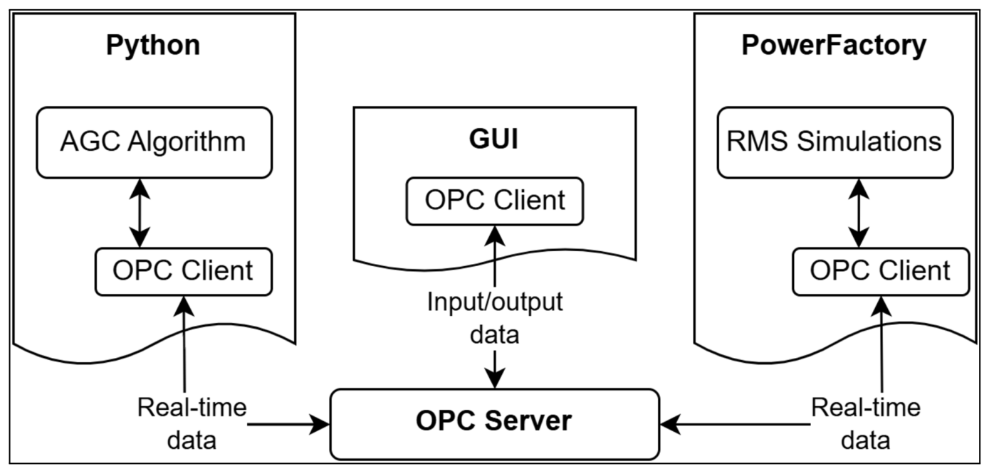
The simulation environment integrates four key interfaces [31]: A Python-based platform for executing the proposed AGC algorithm, DIgSILENT PowerFactoryTM for dynamic simulations, a Graphical User Interface (GUI) for user interaction, and an Open Platform Communications (OPC) interface for real-time data exchange between system components, as shown in Figure 2.
Figure 2.
The simulation and testing environment.
Verification of the proposed AGC scheme involves several sequential steps on the simulation platform. Static power system data is first transferred from PowerFactoryTM to the Python environment to initialize the AGC algorithm. The OPC interface enables real-time data exchange between all interfaces, while RMS time-domain simulations run in parallel. The GUI allows users to configure parameters such as the control cycle, predefined as 4 s and adjustable between 1–5 s in accordance with ENTSO-E policies [12]. During each cycle, the algorithm processes real-time measurements (e.g., frequency and active power) along with AGC modes and reserve settings.
Within this simulation workflow, the adaptive is determined once upon confirmation of each splitting event using a predefined lookup table based on the initial ACE and total inertia contribution. The selected gain is then held constant throughout the separated operation of the corresponding area. Because this selection involves only table indexing and, when required, a single bilinear interpolation, it is performed once per event at negligible computational cost. No iterative optimization, learning process, or model-based prediction is performed during gain determination; consequently, the gain-adaptation mechanism imposes no recurring computational burden within the 4 s AGC control cycle. The required ACE and operating data are available through standard SCADA/EMS infrastructure, while the total inertia contribution can be calculated using unit operating data and stored inertia parameters, supporting practical implementation in TSO environments.
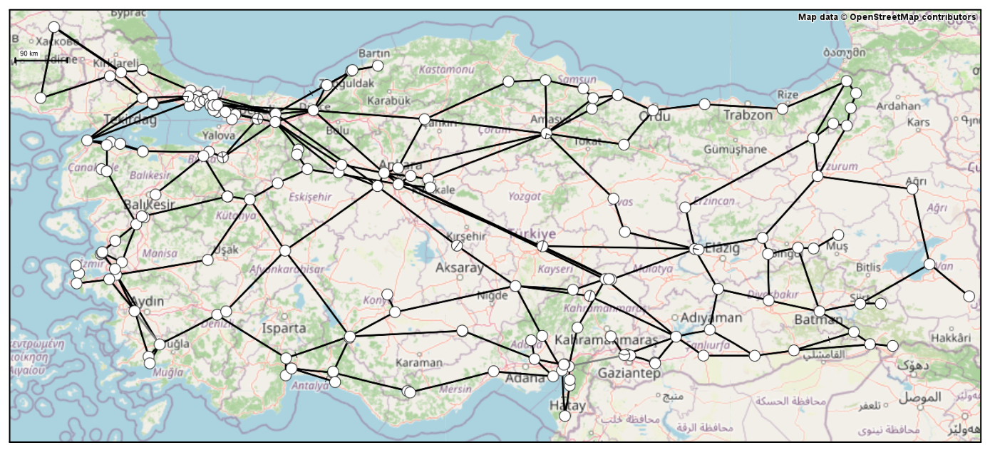
The dynamic system model used for this verification consists of a time-domain RMS representation of the Turkish transmission grid interconnected with a representative ENTSO-E system. While the interconnection structure reflects the real-world topology, generic dynamic models were used for the generators. The network model is shown in Figure 3.
Figure 3.
Representative Turkish Transmission System. White circles represent network buses, while black lines represent transmission lines. The geographical background map is sourced from OpenStreetMap; consequently, some place names appear in their native languages.
3.2. Operational Scenarios
This study defines one base (no-split) and three splitting scenarios (see Table 3) designed to demonstrate the benefits of the adaptive AGC scheme, particularly in improving ACE performance during system splitting. Although these scenarios also supported the correlation analysis between and key network parameters, their primary purpose is to evaluate AGC performance under splitting conditions.
Table 3.
Scenarios and corresponding network parameters.
The splitting scenarios are designed to reflect realistic operational challenges during grid separation and serve as test cases for evaluating the adaptive AGC’s ability to maintain frequency and ACE control. The base case represents normal operation without splitting, where AGC manages frequency and tie-line flows across the entire network. In Scenario 1, the system splits into two areas: Area-1 (ENTSO-E side) remains connected to the external grid, while Area-2 (Isolated side) becomes separated due to high east-to-west power transfers and a weak transmission corridor. This scenario represents a controlled version of the 2015 Turkish blackout [10], offering insight into how AGC could contribute to stability during partial separation. Scenario 2 models a more balanced split, with a relatively even distribution of generation units, inertia, and reserves, allowing performance evaluation under stable and coherent conditions. Scenario 3 simulates a highly asymmetric separation where a small, under-resourced area becomes islanded, challenging the AGC to maintain ACE and frequency stability with limited inertia and reserves. Together, these scenarios provide a comprehensive testbed for validating the proposed adaptive AGC scheme under realistic separation conditions.
4. Simulation Results
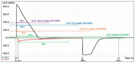
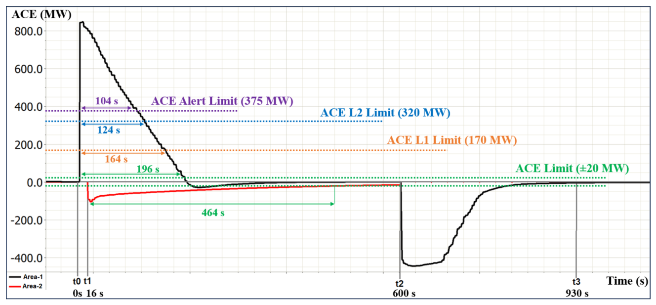
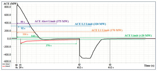
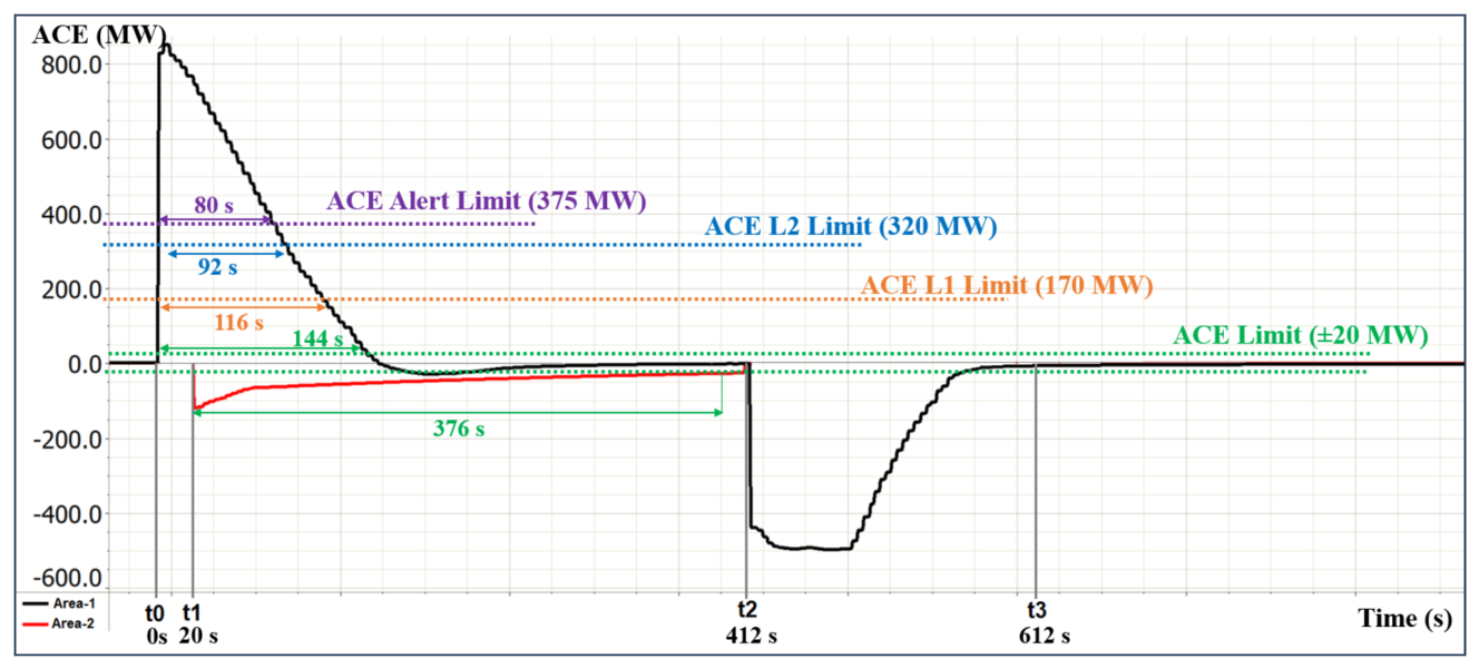
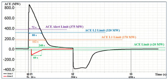
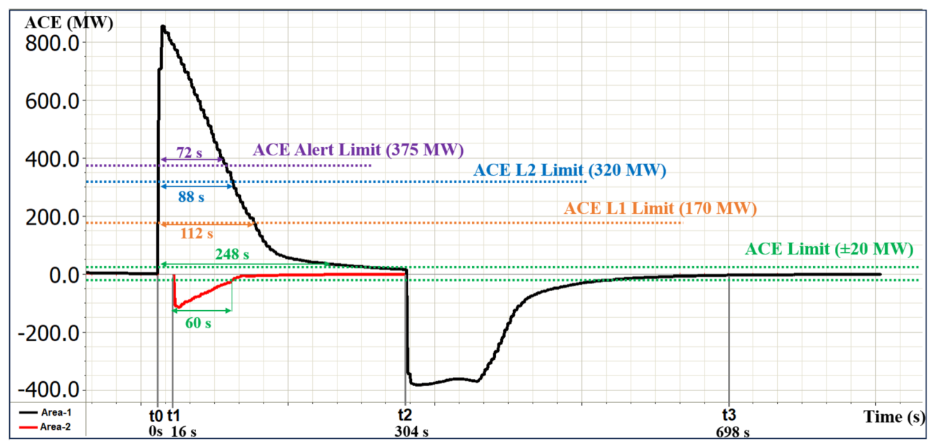
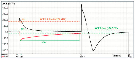
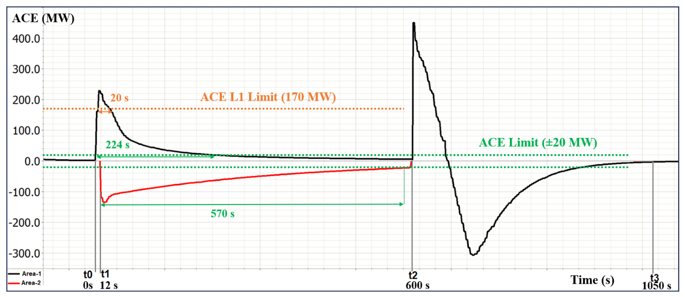
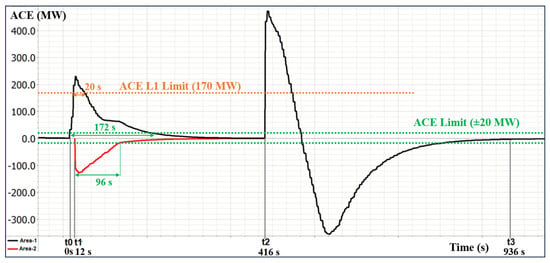
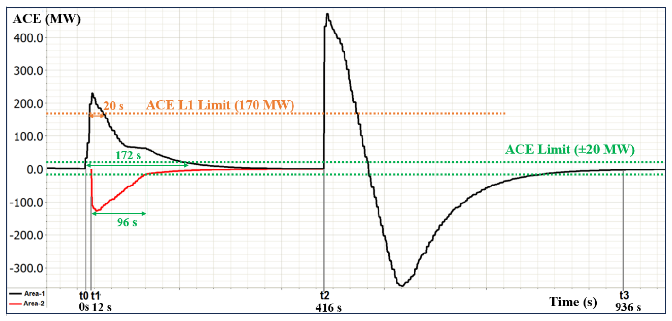
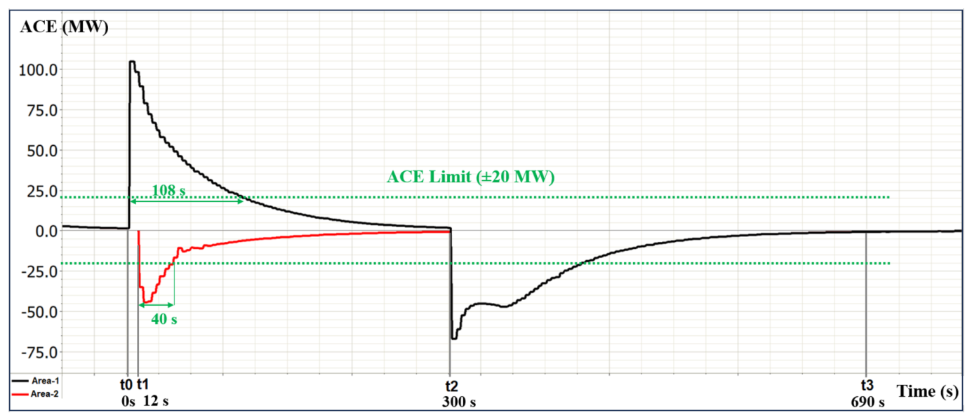
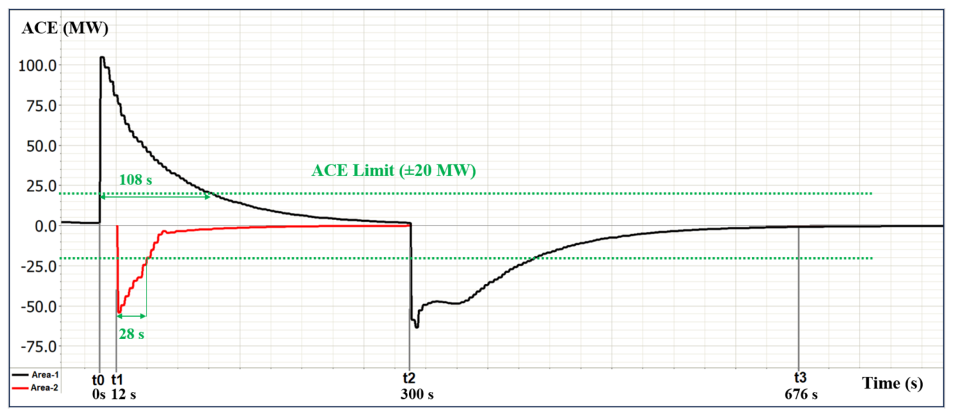
This section presents simulation results for the proposed AGC scheme in multiple scenarios, with the objective of demonstrating operational continuity during splitting and evaluating the effectiveness of adaptive and SLSQP-based reserve activation. System performance is assessed using four ACE-based metrics defined by ENTSO-E [12]. The Normal Operation Band (±20 MW), derived from a 10 mHz frequency deviation applied to TEİAŞ’s bias factor (2000 MW/Hz), represents the acceptable fluctuation range for ACE. The Level-1 (±170 MW) and Level-2 (±320 MW) thresholds are based on TEİAŞ’s historical ACE performance targets, calculated as the average values over the past eight years. The Critical Impact Level (±375 MW) reflects alert states for TSOs and triggers immediate coordination with the RCC and activation of extraordinary measures.
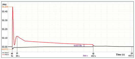
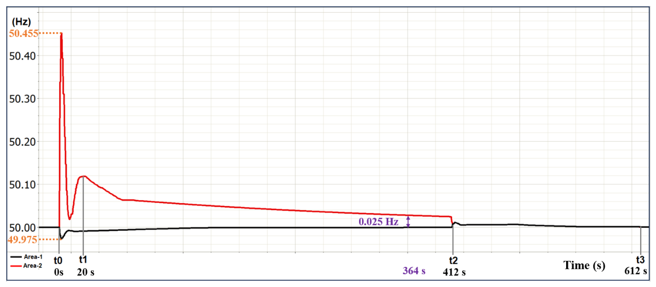
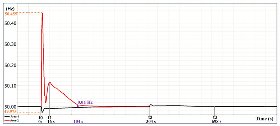
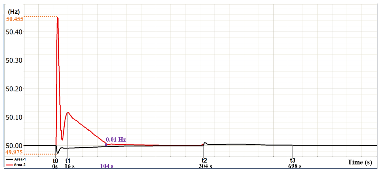
In each scenario, the x-axis denotes time and includes key phases: (onset of splitting), (start of isolated area operations), (merging point), and (post-merging re-stabilization). The black curve represents the ACE/frequency of Area-1 (connected to the external grid), while the red curve corresponds to Area-2 (isolated region), which emerges at and disappears after merging at .
4.1. Results for Scenario 1
Results for Scenario 1 are presented in Figure 4, Figure 5, Figure 6, Figure 7 and Figure 8. Area-1 remains connected to ENTSO-E and operates under tie-line and frequency control. Area-2, however, becomes isolated from the synchronous area and operates independently in frequency control mode. ACE responses are compared across three cases: Case 1 uses static with conventional (market-based) reserve activation; Case 2 applies static with the proposed SLSQP-based reserve strategy; and Case 3 employs adaptive with SLSQP-based reserve activation.
Figure 4.
The ACE value of each area (Case 1: Static & market-based reserve activation).
Figure 5.
The ACE value of each area (Case 2: Static & SLSQP-based reserve activation).
Figure 6.
The ACE value of each area (Case 3: Adaptive & SLSQP-based reserve activation).
Figure 7.
The frequency curve of each area (Case 2: Static & SLSQP-based reserve activation). The black curve represents Area-1, while the red curve represents Area-2.
Figure 8.
The frequency curve of each area (Case 3: Adaptive & SLSQP-based reserve activation). The black curve represents Area-1, while the red curve represents Area-2.
As illustrated in Figure 4, Figure 5 and Figure 6, during the splitting phase ( to ), adaptive with the proposed reserve activation strategy provides faster ACE reduction in Area-2 compared to the static cases. The improvement in Area-1 is more limited, as its lower initial ACE leaves less margin for acceleration. In contrast, static with market-based reserve activation results in slower ACE recovery, while static with SLSQP-based reserve activation improves performance slightly but remains less effective than the adaptive approach.
Figure 7 and Figure 8 show the frequency behavior before, during, and after the splitting event. Both static and adaptive cases exhibit significant frequency deviations in Area-2 at the onset of separation; however, the adaptive control achieves faster recovery to the nominal frequency. This accelerated stabilization enables TSOs to initiate merging (at ) earlier or at a lower frequency delta, allowing a controlled transition to normal operations. These results underscore the benefit of adaptive control in accelerating frequency recovery and reducing the overall time to restore interconnected operation.
4.2. Results for Scenario 2
Scenario 2 evaluates the proposed AGC scheme during a splitting and merging event under altered system conditions, as shown in Figure 9 and Figure 10. As in Scenario 1, the network is divided into Area-1 and Area-2. This scenario compares ACE responses for two cases: Case 1 uses static with the proposed reserve activation strategy, while Case 2 applies adaptive with the same reserve strategy. The market-based reserve case is excluded, as it showed no positive impact on ACE performance in Scenario 1.
Figure 9.
The ACE value of each area in Scenario 2 (Case 1: Static & SLSQP-based reserve activation).
Figure 10.
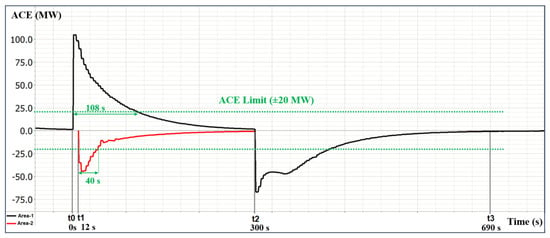
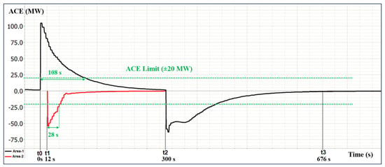
The ACE value of each area in Scenario 2 (Case 2: Adaptive & SLSQP-based reserve activation).
As shown in Figure 9 and Figure 10, during the splitting phase, the adaptive approach improves ACE stabilization in Area-2, enabling faster ACE reduction compared to the static configuration. This enhanced control allows the merging condition to be satisfied earlier and supports more efficient post-splitting recovery. In contrast, improvements in Area-1 are limited due to its initially low ACE. After merging, the AGC must reallocate the available reserves of participating units toward their pre-event market conditions due to the significant reserve transition during splitting.
4.3. Results for Scenario 3
Scenario 3 assesses the performance of the proposed scheme during another split and merging event, as illustrated in Figure 11 and Figure 12. This scenario evaluates ACE responses under two cases: Case 1 uses static with SLSQP-based reserve activation, and Case 2 implements adaptive with the reserve activation strategy.
Figure 11.
The ACE value of each area in Scenario 3 (Case 1: Static & SLSQP-based reserve activation).
Figure 12.
The ACE value of each area in Scenario 3 (Case 2: Adaptive & SLSQP-based reserve activation).
As shown in Figure 11 and Figure 12, during the splitting, the adaptive with the proposed reserve activation reflects sharper improvement in ACE stabilization for Area-2 compared to the static case. This enhanced performance for Area-2 facilitates earlier system merging and more efficient overall stabilization. However, the improvement for Area-1 remains limited due to its relatively low ACE level at the onset of the splitting phase. In this scenario, as shown in the figures, the merging process results in minimal ACE recovery due to the nature of the scenario, which involves a relatively small control area compared to the other.
In scenarios where the initial ACE magnitude in Area-1 is relatively low (i.e., Scenario 3), the achievable improvement through adaptive adjustment is inherently limited. From a control-theoretic perspective, when the control error is already small, the PI-based AGC does not require aggressive corrective action, and the integral term accumulates gradually, resulting in a smooth response with a finite settling time. Consequently, even with a higher , the observable improvement in ACE recovery may remain limited in strongly interconnected areas. This behavior reflects a deliberate balance between correction speed and stability rather than insufficient control performance and is consistent with ENTSO-E operational principles. As a result, the benefits of the adaptive strategy become more pronounced in areas experiencing larger ACE deviations or islanded operation.
4.4. Performance Comparison of AGC Scenarios
This section presents a comparative and quantitative analysis of the proposed AGC scheme across all cases. The performance is evaluated using multiple ACE-based recovery thresholds (375 MW, 320 MW, 170 MW, and 20 MW), ACE overshoots, and frequency deviation convergence. As shown in Table 4, the proposed scheme improves the main post-splitting recovery indicators, especially in islanded areas; however, some individual metrics show trade-offs rather than monotonic improvement. For instance, in Scenario 1, Area-2 ACE recovery to within ±20 MW improves from 464 s (Case 1) to 60 s (Case 3), representing an 87% reduction. Similarly, Case 3 reaches the tighter merging frequency criterion of 0.01 Hz in only 88 s, whereas Case 1 requires 584 s even to reach a residual deviation of 0.025 Hz, indicating that adaptive control enables merging both earlier and at a tighter frequency delta.
Table 4.
AGC performance comparison across scenarios and cases.
In addition to faster convergence in the islanded areas, the proposed scheme mitigates overshoot in the tested cases. For example, in Scenario 1, Case 1 exhibits a 30 MW overshoot in Area-1, whereas no overshoot is observed in Case 3. Moreover, adaptive tuning responds effectively to different system sizes, inertia levels, and ACE profiles. However, the performance improvement is metric-dependent, and some individual indicators, such as the final convergence to the narrow MW band or the post-merging return-to-normal time, may exhibit trade-offs. The longer post-merging return-to-normal time is partly due to earlier merging, since a larger amount of activated reserves must be redistributed after reconnection. Overall, the results show that the proposed adaptive AGC method improves the main post-splitting recovery indicators, particularly in islanded areas, while maintaining ENTSO-E-compliant performance under the tested grid-splitting conditions.
4.5. Sensitivity Analysis
To validate the robustness of the proposed AGC scheme, four sensitivity cases were analyzed with variations in total inertia contribution, generation dispatch, available reserves, and ACE levels. In the first case, both areas experienced reduced inertia and load-generation dispatch. The controller responded with slightly increased values in both areas, maintaining stable ACE and frequency performance as expected. The second case reduced the total inertia contribution in Area-2 only, while keeping Area-1’s inertia contribution unchanged; the load/generation level was reduced in both areas. Since the gain is selected from the total inertia contribution and the initial ACE, only Area-2’s was adjusted while Area-1’s remained unchanged, confirming that the control logic adapts locally without impacting other areas. In the third case, Area-2’s available aFRR was reduced from 715.1 to 579.4 MW. Since is selected from the total inertia contribution and the initial ACE, both of which remained unchanged, the gain and the resulting control performance were unaffected and remained within acceptable limits. Finally, an asymmetric ACE condition was tested by shifting 1000 MW of generation from Area-1 to Area-2. The adaptive controller responded appropriately, adjusting based on the new initial ACE values. A summary of the operating conditions and corresponding control responses for each case is provided in Table 5.
Table 5.
Summary of sensitivity analysis results. Base and perturbed (Sens.) values are reported for each area. Inertia contribution () is given in MW·s; load/generation and aFRR in MW.
4.6. Discussion and Limitations
The proposed AGC scheme demonstrates practical scalability potential for large and complex interconnected power systems. The coherency-based splitting detection and adaptive AGC framework have been validated on a realistic large-scale transmission network model, indicating that the underlying methodology is generalizable beyond the specific test cases considered. The portability of the lookup table is system-dependent: it can be systematically reconstructed for a target network through the same offline correlation-based procedure. Detection robustness can be further enhanced by adaptive threshold tuning, extended observation windows, and complementary indicators such as RoCoF and phase-angle measurements, particularly in PMU-based environments.
Despite the demonstrated effectiveness, certain limitations should be acknowledged. First, as the number of split areas increases, real-time identification of coherent generator groups may become more challenging, which can affect scalability in highly fragmented networks. Second, the simulation scenarios focus on network splitting events without explicitly superimposing large-scale renewable generation fluctuations. Although the sensitivity analyses consider variations in inertia, reserve availability, dispatch, and ACE levels, they do not fully represent composite disturbances involving converter-based renewable generation and rapid renewable power variations. The proposed framework is expected to be extendable to such conditions through recalibration of the lookup table and updated reserve-allocation inputs; however, this study does not claim full validation under high-renewable composite disturbances. Future validation should therefore include renewable ramp events, reduced-inertia operating points, and simultaneous grid-splitting events. Third, the current validation is performed in a SIL environment; therefore, hardware-related effects such as communication delays are not explicitly captured. However, due to the deterministic structure of the adaptive gain-selection mechanism and the demonstrated compatibility of the SLSQP-based reserve allocation with the real-time SIL execution, the proposed AGC scheme is suitable for real-time HIL validation, which is identified as a natural next step toward practical deployment. These limitations do not undermine the practical value of the proposed approach, but rather define clear directions for its extension and real-world implementation.
5. Conclusions
This study proposes a novel adaptive and continuous AGC scheme capable of maintaining stable frequency and tie-line control during power system splitting and reconnection events. The proposed approach ensures uninterrupted AGC operation throughout dynamic network transitions by autonomously managing separated control areas and dynamically adjusting control parameters in response to changing system conditions. A key contribution of the method is the adaptive mechanism, implemented through a correlation-based lookup table, which enables context-aware gain selection while remaining consistent with ENTSO-E operational principles. In addition, the integration of an optimization-based reserve activation strategy enhances system resilience by enabling fast and effective deployment of available reserves, particularly in isolated areas following system separation.
Simulation results demonstrate that the proposed scheme improves the most critical post-splitting recovery indicators compared with conventional static AGC configurations, particularly in islanded areas where adaptive gain selection and reserve reallocation have a stronger effect. The adaptive control approach achieves faster ACE recovery, mitigates overshoot where present, and shortens the duration of separated operation in scenarios with significant islanded-area ACE deviations. These findings are supported by quantitative performance indicators, including ACE recovery time, overshoot magnitude, and merging frequency deviation, as well as sensitivity analyses conducted under varying inertia, reserve availability, and dispatch conditions. Overall, the results indicate that continuous and adaptive AGC operation can contribute to maintaining system stability during grid-splitting and reconnection events, and they establish a practical foundation for future developments in scalable and resilient LFC solutions for TSO applications.
Author Contributions
Conceptualization, A.T. and A.N.G.; methodology, A.T. and A.N.G.; software, A.T.; validation, A.T.; formal analysis, A.T.; investigation, A.T.; resources, A.T. and A.N.G.; data curation, A.T.; writing—original draft preparation, A.T.; writing—review and editing, A.T. and A.N.G.; visualization, A.T. and A.N.G.; supervision, A.N.G. All authors have read and agreed to the published version of the manuscript.
Funding
This research received no external funding.
Data Availability Statement
The datasets generated and analyzed during this study are not publicly available but are available from the corresponding author on reasonable request.
Acknowledgments
The authors acknowledge ASELSAN A.Ş. for providing resources and assistance that supported the development and validation of this research.
Conflicts of Interest
Author A.T. is employed by ASELSAN A.Ş. The remaining authors declare that the research was conducted in the absence of any commercial or financial relationships that could be construed as a potential conflict of interest.
Abbreviations
The following abbreviations are used in this manuscript:
| ACE | Area Control Error |
| aFRR | Automatic Frequency Restoration Reserve |
| AGC | Automatic Generation Control |
| EMS | Energy Management System |
| ENTSO-E | European Network of Transmission System Operators for Electricity |
| Frequency deviation | |
| GUI | Graphical User Interface |
| H | Inertia constant |
| Total inertia contribution | |
| HIL | Hardware-in-the-loop |
| Integral gain of the AGC PI controller | |
| OPC | Open Platform Communications |
| PI | Proportional–Integral controller |
| PMU | Phasor Measurement Unit |
| RCC | Regional Coordination Center |
| RMS | Root Mean Square |
| RoCoF | Rate of Change of Frequency |
| LFC | Load Frequency Control |
| SCADA | Supervisory Control and Data Acquisition |
| SIL | Software-in-the-loop |
| SLSQP | Sequential Least Squares Programming |
| TSO | Transmission System Operator |
References
- Ullah, K.; Basit, A.; Ullah, Z.; Aslam, S.; Herodotou, H. Automatic Generation Control Strategies in Conventional and Modern Power Systems: A Comprehensive Overview. Energies 2021, 14, 2376. [Google Scholar] [CrossRef] [Scilit]
- Lam, L.H.; Nam, L.K.; Dung, N.K.T.; Hieu, N.H. Two-Area Automatic Generation Control for Power Systems with Highly Penetrating Renewable Energy Sources. Electronics 2024, 13, 2907. [Google Scholar] [CrossRef] [Scilit]
- Zhang, S. Review of the Development of Power System Out-of-Step Splitting Control and Some Thoughts on the Impact of Large-Scale Access of Renewable Energy. Energy AI 2024, 16, 100357. [Google Scholar] [CrossRef] [Scilit]
- ENTSO-E. ENTSO-E Annual Report 2021; ENTSO-E: Brussels, Belgium, 2021. [Google Scholar]
- ENTSO-E. PROJECT INERTIA—PHASE II: Updated Frequency Stability Analysis in Long Term Scenarios, Relevant Solutions and Mitigation Measures; Technical Report; ENTSO-E: Brussels, Belgium, 2023. [Google Scholar]
- ENTSO-E. Continental Europe Synchronous Area Separation on 08 January 2021: Executive Summary; ENTSO-E: Brussels, Belgium, 2021. [Google Scholar]
- Fotis, G.; Vita, V.; Maris, T.I. Risks in the European Transmission System and a Novel Restoration Strategy for a Power System After a Major Blackout. Appl. Sci. 2023, 13, 83. [Google Scholar] [CrossRef] [Scilit]
- ENTSO-E. Continental Europe Synchronous Area Separation on 24 July 2021; Technical Report; ENTSO-E: Brussels, Belgium, 2021. [Google Scholar]
- ENTSO-E. Grid Incident in South-Eastern Part of the Continental Europe Power System—Update; ENTSO-E: Brussels, Belgium, 2024. [Google Scholar]
- Project Group Turkey. Report on Blackout in Turkey on 31st March 2015; ENTSO-E Technical Report; ENTSO-E: Brussels, Belgium, 2015. [Google Scholar]
- Saribulut, L.; Ok, G.; Ameen, A. A Case Study on National Electricity Blackout of Turkey. Energies 2023, 16, 4419. [Google Scholar] [CrossRef] [Scilit]
- ENTSO-E. Synchronous Area Operational Agreement for the Synchronous Area CE—Annex 1: Policy on Load-Frequency Control and Reserves; ENTSO-E: Brussels, Belgium, 2024. [Google Scholar]
- Peddakapu, K.; Mohamed, M.R.; Srinivasarao, P.; Arya, Y.; Leung, P.K.; Kishore, D.J.K. A State-of-the-Art Review on Modern and Future Developments of AGC/LFC of Conventional and Renewable Energy-Based Power Systems. Renew. Energy Focus 2022, 43, 146–171. [Google Scholar] [CrossRef] [Scilit]
- Verma, R.; Gawre, S.K.; Patidar, N.P.; Nandanwar, S. A State-of-the-Art Review on the Opportunities in Automatic Generation Control of Hybrid Power System. Electr. Power Syst. Res. 2023, 226, 109945. [Google Scholar] [CrossRef] [Scilit]
- Ranjan, M.; Shankar, R. A Literature Survey on Load Frequency Control Considering Renewable Energy Integration in Power System: Recent Trends and Future Prospects. J. Energy Storage 2021, 45, 103717. [Google Scholar] [CrossRef] [Scilit]
- Güler, Y.; Nalbantoğlu, M.; Kaya, I. Cascade Controller Design via Controller Synthesis for Load Frequency Control of Electrical Power Systems. Turk. J. Electr. Eng. Comput. Sci. 2024, 32, 285–304. [Google Scholar] [CrossRef] [Scilit]
- Ashfaq, T.; Hassan, M.A.; Ahmad, S.; Alassaf, A.; Khan, I. Automatic Generation Control in Renewables-Integrated Interconnected Power Systems Using Adaptive-PID Control. Sustainability 2024, 16, 5735. [Google Scholar] [CrossRef] [Scilit]
- Bevrani, H.; Daneshfar, F.; Hiyama, T. A New Intelligent Agent-Based AGC Design with Real-Time Application. IEEE Trans. Syst. Man Cybern. Part C (Appl. Rev.) 2012, 42, 994–1002. [Google Scholar] [CrossRef] [Scilit]
- Tan, C.; Li, Y.; Lan, Q.; Xiao, X.; Ding, Q.; Zhang, X.; Wang, M.; Teng, X.; Wang, Y. Multi-Area Automatic Generation Control Scheme Considering Frequency Quality in Southwest China Grid: Challenges and Solutions. IEEE Access 2020, 8, 199813–199828. [Google Scholar] [CrossRef] [Scilit]
- Patel, N.C.; Sahu, B.K.; Debnath, M.K. Automatic Generation Control Analysis of Power System with Nonlinearities and Electric Vehicle Aggregators with Time-Varying Delay Implementing a Novel Control Strategy. Turk. J. Electr. Eng. Comput. Sci. 2019, 27, 3040–3054. [Google Scholar] [CrossRef] [Scilit]
- Nguyen, N.; Huang, Q.; Dao, T. An Investigation of Intelligent Controllers Based on Fuzzy Logic and Artificial Neural Network for Power System Frequency Maintenance. Turk. J. Electr. Eng. Comput. Sci. 2016, 24, 2893–2909. [Google Scholar] [CrossRef] [Scilit]
- Wazir, A.B.; Alghamdi, S.; Alobaidi, A.; Alhussainy, A.A.; Milyani, A.H. Efficient Frequency Management for Hybrid AC/DC Power Systems Based on an Optimized Fuzzy Cascaded PI-PD Controller. Energies 2024, 17, 6402. [Google Scholar] [CrossRef] [Scilit]
- Li, B.; Chen, J. Automatic Generation Control Strategy Based on Deep Forest. IEEE Access 2023, 11, 23495–23504. [Google Scholar] [CrossRef] [Scilit]
- Yang, F.; Shao, X.; Zhou, B.; Shi, Y.; Shen, Y.; Li, D. Data-Driven Automatic Generation Control Based on Learning to Coordinate and Teach Reinforcement Mechanism. Symmetry 2025, 17, 854. [Google Scholar] [CrossRef] [Scilit]
- Zeng, G.Q.; Xie, X.Q.; Chen, M.R. An Adaptive Model Predictive Load Frequency Control Method for Multi-Area Interconnected Power Systems with Photovoltaic Generations. Energies 2017, 10, 1840. [Google Scholar] [CrossRef] [Scilit]
- Chen, K.; Lin, J.; Qiu, Y.; Liu, F.; Song, Y. Model Predictive Control for Wind Farm Power Tracking With Deep Learning-Based Reduced Order Modeling. IEEE Trans. Ind. Inform. 2022, 18, 7484–7493. [Google Scholar] [CrossRef] [Scilit]
- He, J.; Shi, C.; Wei, T.; Jia, D. Stochastic Model Predictive Control of Hybrid Energy Storage for Improving AGC Performance of Thermal Generators. IEEE Trans. Smart Grid 2022, 13, 393–405. [Google Scholar] [CrossRef] [Scilit]
- Oshnoei, A.; Kheradmandi, M.; Khezri, R.; Mahmoudi, A. Robust Model Predictive Control of Gate-Controlled Series Capacitor for LFC of Power Systems. IEEE Trans. Ind. Inform. 2021, 17, 4766–4776. [Google Scholar] [CrossRef] [Scilit]
- Bhagat, S.K.; Babu, N.R.; Saikia, L.C.; Chiranjeevi, T.; Devarapalli, R.; García Márquez, F.P. A Review on Various Secondary Controllers and Optimization Techniques in Automatic Generation Control. Arch. Comput. Methods Eng. 2023, 30, 3081–3111. [Google Scholar] [CrossRef] [Scilit]
- Ram Babu, N.; Bhagat, S.K.; Saikia, L.C.; Chiranjeevi, T.; Devarapalli, R.; García Márquez, F.P. A Comprehensive Review of Recent Strategies on Automatic Generation Control/Load Frequency Control in Power Systems. Arch. Comput. Methods Eng. 2023, 30, 543–572. [Google Scholar] [CrossRef] [Scilit]
- Temiz, A.; Guven, A.N. An AGC Algorithm for Multi-Area Power Systems in Network Splitting Conditions. In Proceedings of the 2023 IEEE PES GTD International Conference and Exposition (GTD), Istanbul, Turkiye, 22–25 May 2023; pp. 77–81. [Google Scholar] [CrossRef] [Scilit]
- Kundur, P. Power System Stability and Control; McGraw-Hill: New York, NY, USA, 1994. [Google Scholar]
- Sung, S.W.; Lee, J.; Lee, I.B. Proportional–Integral–Derivative Controller Tuning. In Process Identification and PID Control; John Wiley & Sons (Asia) Pte Ltd.: Singapore, 2009; pp. 151–199. [Google Scholar]
- Chattamvelli, R. Pearson’s Correlation. In Correlation in Engineering and the Applied Sciences—Synthesis Lectures on Maths & Statistics; Springer: Cham, Switzerland, 2024. [Google Scholar] [CrossRef] [Scilit]
- Gribbon, K.T.; Bailey, D.G. A Novel Approach to Real-Time Bilinear Interpolation. In Proceedings of the DELTA 2004 Second IEEE International Workshop on Electronic Design, Test and Applications, Perth, Australia, 28–30 January 2004; pp. 126–131. [Google Scholar] [CrossRef] [Scilit]
- Bashishtha, T.K.; Singh, V.P.; Yadav, U.K.; Varshney, T. Reaction Curve-Assisted Rule-Based PID Control Design for Islanded Microgrid. Energies 2024, 17, 1110. [Google Scholar] [CrossRef] [Scilit]
- Torrisi, G.; Grammatico, S.; Smith, R.S.; Morari, M. A Variant to Sequential Quadratic Programming for Nonlinear Model Predictive Control. In Proceedings of the 2016 IEEE 55th Conference on Decision and Control (CDC), Las Vegas, NV, USA, 12–14 December 2016; pp. 2814–2819. [Google Scholar] [CrossRef] [Scilit]

Disclaimer/Publisher’s Note: The statements, opinions and data contained in all publications are solely those of the individual author(s) and contributor(s) and not of MDPI and/or the editor(s). MDPI and/or the editor(s) disclaim responsibility for any injury to people or property resulting from any ideas, methods, instructions or products referred to in the content. |
© 2026 by the authors. Licensee MDPI, Basel, Switzerland. This article is an open access article distributed under the terms and conditions of the Creative Commons Attribution (CC BY) license.