


Abstract
Exploitation of geothermal energy stored in hot dry rocks requires the application of enhanced geothermal system (EGS) technology, which enables artificial enhancement of reservoir permeability and improved heat extraction efficiency. This study addresses the assessment of geothermal potential in the Gorzów Block (NW Poland), an area identified as prospective for a CO2-enhanced geothermal system (CO2-EGS). Geological modeling was used as the primary tool to integrate structural, petrophysical, and thermal data in order to reduce exploration uncertainty and identify the most favorable reservoir interval. The workflow included structural interpretation and parameter modeling of key reservoir properties, with particular emphasis on porosity, clay mineral content, permeability, density, and temperature distribution. The results indicate that the optimal reservoir zone is located at depths of 4100–4300 m below ground level within Lower Permian volcanic formations (Autunian). At this depth, reservoir temperature reaches approximately 145 °C. The analyzed rocks exhibit low porosity (0.04), moderate clay content (0.12), very low permeability (0.008 mD), and an average density of 2.59 g/cm3, indicating tight reservoir conditions requiring hydraulic stimulation. The assessment is subject to limitations associated with the availability and spatial distribution of subsurface data, as well as uncertainties inherent in geological and petrophysical modeling of deep formations. Therefore, the identified reservoir interval and estimated parameters should be regarded as a preliminary assessment that requires further verification through additional exploration and reservoir testing. Nevertheless, the study confirms the value of integrated geological modeling for identifying deep geothermal reservoirs and supporting decision-making in EGS site selection.
1. Introduction
Enhanced geothermal systems (EGSs) represent one of the key technologies enabling the exploitation of geothermal energy stored in hot dry rocks, which lack natural permeability and formation fluids. Their operation is based on the artificial creation or enhancement of fracture systems through hydraulic stimulation, allowing the circulation of a working fluid and the efficient extraction of heat from the rock mass [1,2,3]. From a global perspective, EGS systems are considered an important component of the future energy mix, particularly in regions with limited hydrothermal resources, and their development is closely linked to the geological, tectonic, and petrophysical conditions of the rock medium [4]. An important direction in the development of this technology is the use of carbon dioxide as a working fluid (CO2-EGS). This concept was proposed by Brown [5], who highlighted the potential benefits of using supercritical CO2 instead of water, including improved flow properties and enhanced heat exchange efficiency. This idea was further developed by Pruess [6] and Randolph and Saar [7], who demonstrated that CO2-EGS systems can simultaneously serve as a means of energy production and geological CO2 sequestration. Such an approach aligns with the concept of a low-emission economy, combining the development of renewable energy sources with the reduction in greenhouse gas emissions. In this context, it is also emphasized that the use of supercritical CO2 as a working fluid offers both energetic and environmental benefits; however, its overall environmental footprint—particularly associated with the construction and installation phase of the system—should be carefully analyzed and minimized within a life cycle assessment framework [8].
In Poland, the potential for the development of EGS systems has been the subject of numerous studies, which indicate favorable conditions within the Polish Lowlands. Early works [9] emphasized the importance of Permian–Mesozoic structures as potential targets for petrothermal systems. Review studies concerning Poland and the Baltic Basin region point to a broad geothermal potential resulting from the presence of deep structures with elevated thermal parameters. Detailed studies for the Gorzów Block confirm that it is one of the most promising regions for the implementation of CO2-EGS technology. Petrophysical analyses of Lower Permian formations indicate the presence of rocks with suitable reservoir properties, including volcanic rocks and breccias, which may function as geothermal reservoirs [10]. Additionally, analyses of elastic properties and brittleness parameters confirm the susceptibility of these rocks to effective hydraulic stimulation [3]. Within the EnerGizerS project, the significance of these structures in the context of implementing EGS systems using CO2 as a working fluid was also highlighted [11]. Comprehensive multi-criteria analyses regarding site selection and technology choice for CO2-EGS systems indicate that the Gorzów Block meets a number of key technical and environmental criteria, making it particularly suitable for the deployment of such systems [12]. At the same time, it is emphasized that the development of such installations requires the integration of knowledge from geology, reservoir engineering, and numerical modeling. The reservoir parameters estimated in this study constituted a key input for further numerical analyses of CO2-EGS system performance. Based on these parameters, simulations of fluid flow and heat exchange were carried out, taking into account petrophysical properties of rocks, thermal conditions, and CO2 injection scenarios. For the Gorzów Block, the results of numerical modeling indicate the possibility of achieving stable thermal energy production and power generation on the order of several megawatts per well doublet, while maintaining long-term system efficiency [13].
The presented work constitutes one of the key components of the EnerGizerS project and fills the gap between petrophysical analyses and geothermal potential assessments on the one hand and subsequent numerical simulations of the CO2-EGS system performance in the Gorzów Block on the other. The results of the geological modeling presented in this study provided the direct basis for developing the reservoir conceptual model and preparing input data for further numerical analyses. Without a comprehensive geological model integrated with laboratory-derived petrophysical data, reliable simulations of geothermal system operation would be incomplete.
In contrast to previously published studies, which focused on individual reservoir parameters, multi-criteria site selection, or numerical modeling of fluid flow and heat transfer processes, the present study introduces an integrated approach to the construction of a three-dimensional geological model based on the interpretation of available geological data and laboratory measurements. The novelty of this work lies primarily in the integration of these diverse datasets into a coherent spatial model, enabling the identification of the most prospective reservoir interval and providing the foundation for subsequent numerical simulations of the CO2-EGS geothermal system.
The efficiency of EGS systems is strongly dependent on reservoir parameters, particularly effective permeability and the degree of fracture system development, which control CO2 flow and the intensity of heat exchange [3,14]. Although CO2-EGS systems have not yet been commercially implemented in Poland, they represent a promising direction for the development of renewable energy. Their implementation may contribute to increased utilization of geothermal resources, improved energy security, and reduced CO2 emissions through the integration of geothermal energy production with carbon dioxide sequestration [6,7,11]. Proper design of CO2-EGS installations requires a detailed characterization of reservoir parameters. In this context, geological modeling plays a key role as the primary tool integrating geological, geophysical, and well data [15]. It enables the determination of the spatial distribution of parameters such as porosity, permeability, and thermal properties of rocks, as well as the identification of optimal zones for hydraulic stimulation [13]. The results of modeling form the direct basis for further system performance simulations.
Geological modeling in the Gorzów Block area was carried out using Petrel software (version number 2020.4), which enables the integration of geological, geophysical, and well data and the construction of three-dimensional structural and petrophysical models. This tool enables the representation of the geological framework, including the distribution of parameters such as porosity and permeability, which is crucial for the analysis of CO2-EGS systems. As a result, it was possible to develop a geological model forming the basis for further numerical analyses. The modeling was conducted in two stages: initially, a larger regional model was developed, followed by a reduction in the modeling area to a local model centered on the OśnoIG-2 reference well.
Interpretation of all obtained results enabled the identification of a key reservoir zone for CO2-EGS at depths of 4200–4300 m below ground level. All available geological data were used in the modeling, including new laboratory data obtained within the EnerGizerS project, such as petrophysical parameters determined from laboratory analyses of drill cores. These data, described in detail in [10], allowed for a more accurate representation of rock petrophysical properties and a better assessment of the reservoir potential of the analyzed formation.
2. Geological Characterization of the Modeled Area
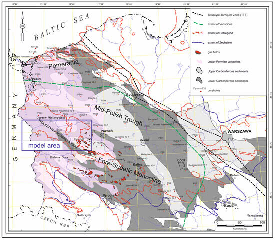
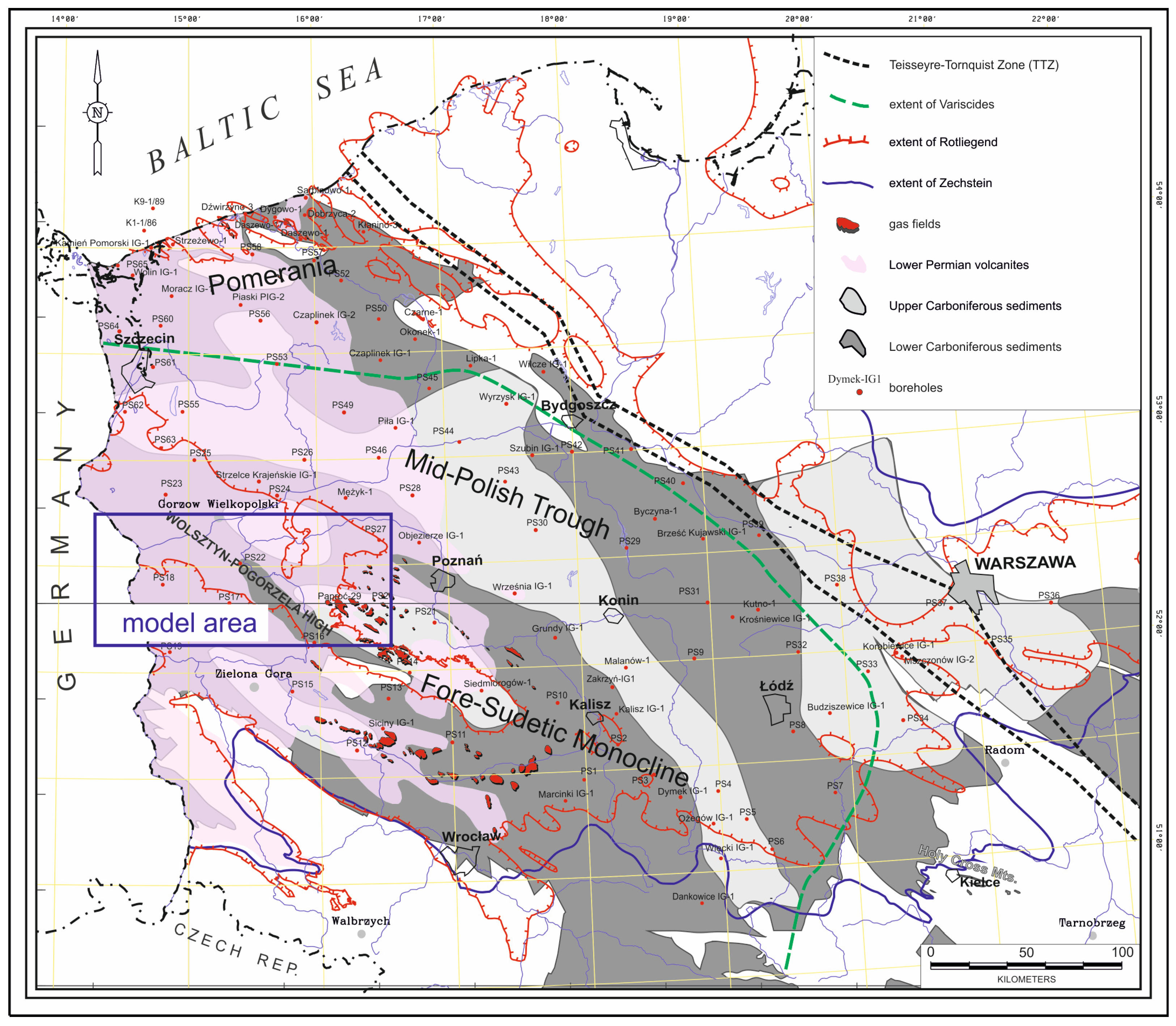
The study area is located in north-western Poland and encompasses the region of the Gorzów Block (Figure 1). The Gorzów Block is a regional geological unit [16,17] that has been intensively studied in recent decades due to the occurrence of oil and gas deposits within the Zechstein formations [18]. Its sedimentary development, thermal history, subsidence, and Moho surface configuration indicate an asymmetric, rift-like character, and its evolution began at the Carboniferous–Permian transition.
Figure 1.
Study area shown in relation to the subcrops of Lower Permian volcanic rocks and Lower–Upper Carboniferous complexes in the Polish Lowlands (modified after [16]).
Sedimentary and subvolcanic Rotliegend rocks are widely distributed in the area. Volcanic rocks are also present, with local thicknesses exceeding 1000 m. Almost the entire Gorzów Block is covered by lava flows and pyroclastic rocks [19,20]. Volcanic occurrences within the Gorzów Block show continuity toward the west [21].
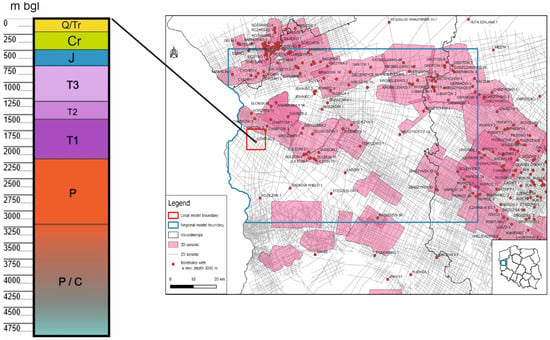
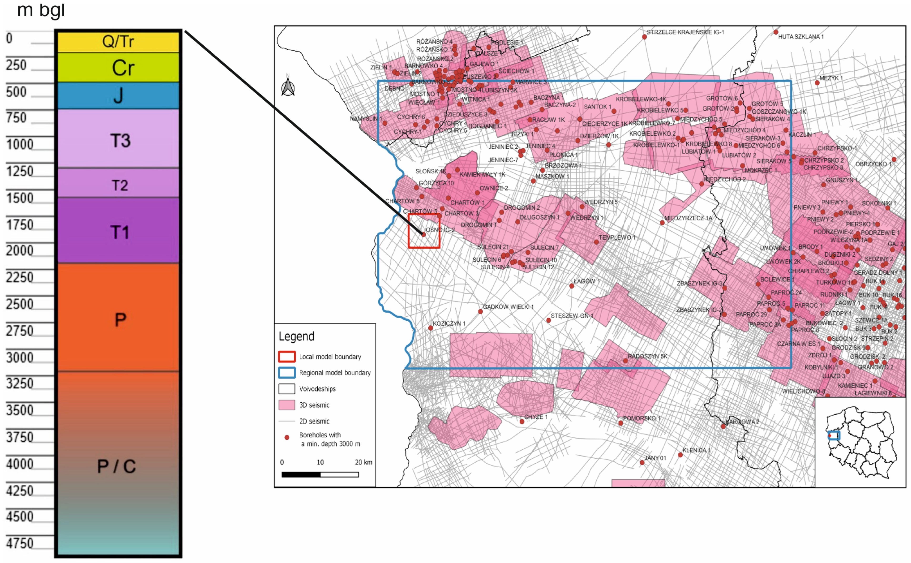
The geological setting of the area is closely related to the evolution of the Carboniferous source rocks of the Variscan foreland basin, which represent the primary source of hydrocarbons in Rotliegend and Zechstein reservoirs [22]. This is of particular importance due to German experience with the Groß Schönebeck EGS installation, which utilizes Lower Permian sandstones and volcanic rocks as geothermal reservoirs at depths of approximately 4000 m [23]. These rock types also occur in the Polish part of the basin and constitute one of the key factors in selecting this region for further modeling studies. The reference borehole providing information on the geological structure of this area is the Ośno IG-2 well (Figure 2), located in the village of Radówek, approximately 10 km west of Ośno, and thoroughly documented in [24]. This borehole was drilled between 1971 and 1973 as part of oil and gas exploration on the Fore-Sudetic Monocline. The main objective of the drilling was to investigate the Permian basement formations and assess their bitumen potential. The Permian basement was not reached at a depth of 4500 m; therefore, the borehole was deepened to 4950 m. In the borehole profile, a thick rock complex underlying the Zechstein deposits was identified, encompassing both Lower and Upper Rotliegend units. The lower part of the complex (down to approximately 3275 m) consists mainly of volcanic rocks, whereas the upper part, occurring at depths of 3275.5–3209.5 m, is composed predominantly of clastic rocks, which gradually transition upward into Zechstein deposits.
Figure 2.
Location of regional and local parametric models against the background of the geological data with chronostratigraphic profile of Ośno IG-2 borehole (according to [25]).
3. Materials and Methods
Modeling was carried out using the specialized software Petrel (version number 2020.4) in two steps: first, a regional-scale model was developed, followed by a refinement into a local model centered around the reference borehole Ośno IG-2 (Figure 2). The regional model covers an area of approximately 7245 km2, whereas the local model covers only 64 km2. Modeling was carried out using Petrel in two main steps. First, a regional-scale model was developed, followed by the construction of a refined local model centered on the Ośno IG-2 reference borehole (Figure 2). The regional model covers an area of approximately 7245 km2, whereas the local model is limited to 64 km2 in the immediate vicinity of the well.
The local model represents a downscaled refinement of the regional geological framework and preserves all key geological elements, including structural boundaries, stratigraphic horizons, reservoir architecture, and petrophysical properties. This ensures full consistency with the regional geological interpretation and provides a reliable basis for subsequent simulation studies.
The local model serves as the foundation for the conceptual reservoir model, which is further used in dynamic simulations of the CO2-EGS system. Its spatial extent and geometry are inherited directly from the regional model and define the boundary conditions for both conceptual and dynamic modeling.
The geometric framework of the local model was constructed using a simple grid with a horizontal resolution of 25 × 25 m and an average vertical increment of 13.56 m. This higher resolution enables a precise fit to petrophysical interpretations derived from the Ośno IG-2 well logs.
Petrophysical properties were estimated using a two-step workflow: first, regional model properties were upscaled to the local grid, and subsequently refined in Petrel using kriging for local-scale updates around the well, with a search radius of 5000 m.
Within the regional model area, 120 boreholes with depths of at least 3000 m were drilled with the aim of penetrating Upper Permian hydrocarbon-bearing formations (Figure 2). Of these, only 17 boreholes exceed 3500 m in depth, and only five penetrate the Carboniferous, with the Ośno IG-2 well (4950 m) being the deepest. Consequently, Lower Permian (Autunian) and Carboniferous formations remain poorly constrained by drilling data. Within the regional model domain, 3D seismic data cover an area of 3846 km2, which represents approximately 53% of the total model area. This is considered relatively good coverage compared to other regions in Poland. In contrast, the local model is covered by 3D seismic data over only about 8.26 km2. More than 1000 two-dimensional (2D) seismic surveys have been conducted across the regional model area, with a cumulative length exceeding 14,100 km. Within the local model area, the total length of 2D seismic profiles is approximately 128 km, consisting of 29 intersecting lines. Although the Gorzów Block is relatively well constrained by drilling and seismic data compared to other regions in Poland, the quality of seismic imaging below the Zechstein is generally poor, which introduces uncertainty in the interpretation of deeper Lower Permian and Carboniferous formations.
The input data for structural modeling consisted of structural maps developed based on the Gorzów Block model prepared by the Polish Geological Institute (PGI) in Warsaw [26], as well as maps of the Carboniferous, Autunian, and Rotliegend formations developed at AGH prior to 2010 [25,26,27] and subsequently updated. The geological model of the Gorzów Block [26] represents the upper 5000 m of the sedimentary succession, from the top of the Carboniferous to the Quaternary. The model is based on the most comprehensive geological dataset available for the area, including 23 seismic volumes covering a total of 5500 square kilometers, more than a thousand 2D seismic lines, and wireline logs from 300 deep boreholes [25,26]. For modeling purposes, only four key maps were selected from this dataset: the Zechstein top [22], the Rotliegend top and the sedimentary Autunian thickness map and volcanic Autunian thickness maps [19,20,21]. The structural and thickness maps of the Rotliegend, the sedimentary Autunian, and the Lower and Upper Carboniferous tops [19,20,21] extend laterally to the north, south, and east, as well as vertically within the PGI geological model. In addition, updates were applied to the reprocessed sedimentary Upper Rotliegend maps, as well as to the structural and thickness maps of the Lower and Upper Carboniferous (sedimentary), the sedimentary and volcanic Autunian, and the Zechstein formations [19,20,21,22]. The set of regional maps was used to define the geometric framework of the model and applied in the first regional phase of modeling. Finally horizons were introduced to the regional and local 3D structural models during the “Make Horizons” process of the Corner Point Grid method. After completing the “Make Horizons” process, the initial input surfaces were replaced with structured horizons. At this stage, the zonation of the model becomes clearly defined. Based on horizons, seven main geological zones were distinguished, each with their own properties: Zechstein, Sedimentary Upper Rotliegend, Upper Autunian, Volcanic Autunian, Lower Autunian, Upper Carboniferous, and Lower Carboniferous. Each zone was divided into layers. The vertical layering resolution was selected according to the volatility of the well logs. The final geocellural model is composed of 575 thousand cells. Despite its regional extent, the model requires moderate to high resolution in both horizontal and vertical directions to ensure accurate fitting between the generated structures and input datasets, such as well logs. This level of detail is achieved using Petrel modeling tools, particularly the Simple Grid (SG) and, more importantly, Corner Point Gridding (CPG) methods. This type of modeling approach is commonly referred to as pillar gridding or a surface-based approach. In the CPG method, faults are initially represented as pillar-like elements, while geological horizons are modeled as smooth surfaces. Subsequently, geological layers are constructed based on predefined topological relationships between these elements. The Lower Carboniferous and Zechstein complexes are not relevant to the primary assessment of the potential for applying combined CCS and EGS technologies; therefore, they were modeled at a lower resolution and serve as the lower and upper boundaries of the model. Given the regional-scale nature of the study, a relatively simple layering approach was adopted. The stratigraphic complexes were subdivided using proportional layering, with a minimum layer thickness of 1 m, generated upward from the base of each complex. The resultant structural model covers approximately 7245 km2 and includes eight horizons and seven complexes (zones), subdivided into 140 layers. Despite a relatively coarse grid resolution (ΔX × ΔY × ΔZ ≈ 501 × 501 × ~30 m), the model comprises 4,433,240 cells, providing a reasonable level of accuracy in representing structural trends (Table 1).
Table 1.
Geometry of the regional structural model.
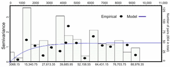
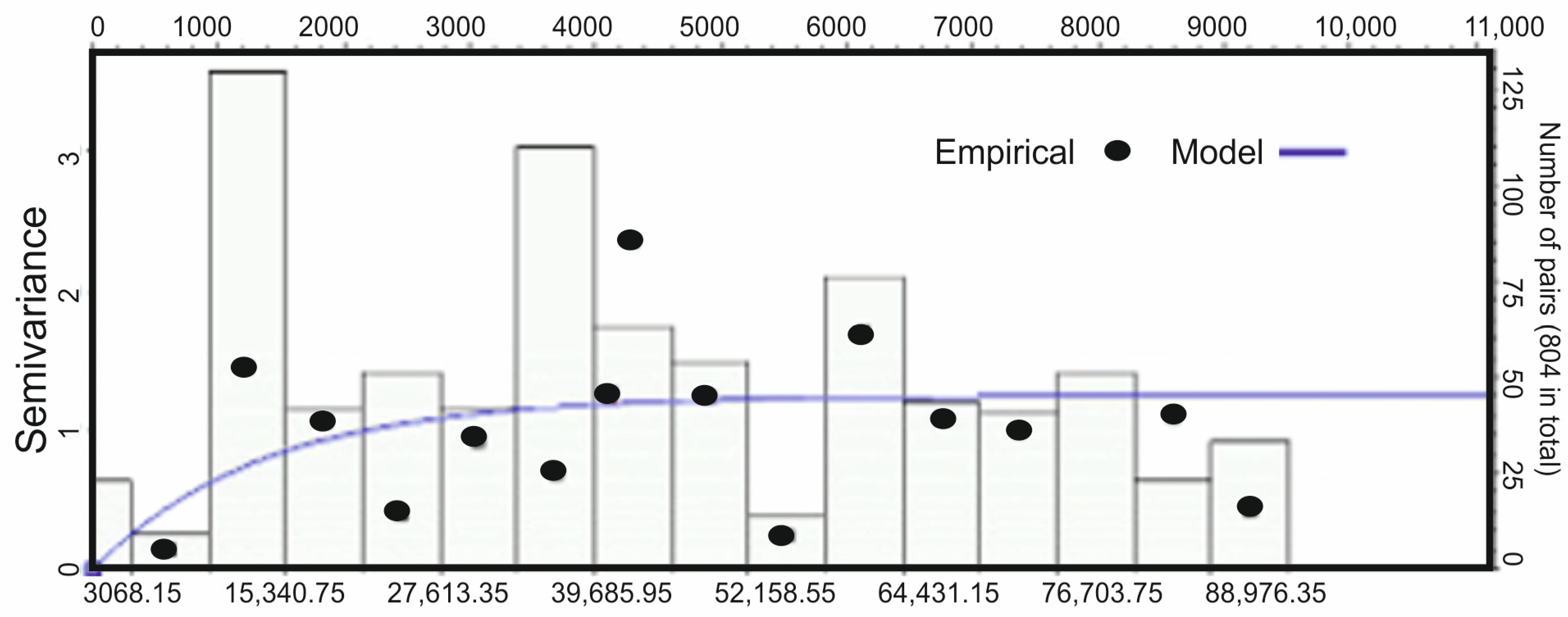
The presented structural framework was used to estimate regional parametric models of temperature (TEMP), porosity (PHI), shale volume (VSH), and bulk density (RHOB). The modeling procedure followed standard data analysis workflows, including normal transformation of the data and subsequent variogram modeling (Figure 3).
Figure 3.
Example of semivariogram constructed for regional-scale modeling purposes (VSH/Rotliegend).
These analyses were conducted separately for each variable and zone and then used in the modeling process. The dominant modeling algorithm was co-kriging. The variogram ranges are very large, varying between 37 and 67 km. The observed variability is isotropic or nearly isotropic.
The input data for the first stage of parametric modeling of porosity (PHI) and shale volume (VSH) were geophysical logs from 34 wells located over the area of the model. In the area of research, regional and local parametric models were enriched with the bulk density model (RHOB), which was based on the results of RHOB model prepared by PGI—NRI [26].
4. Results
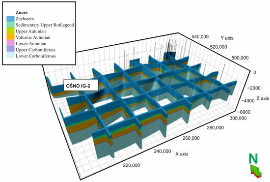
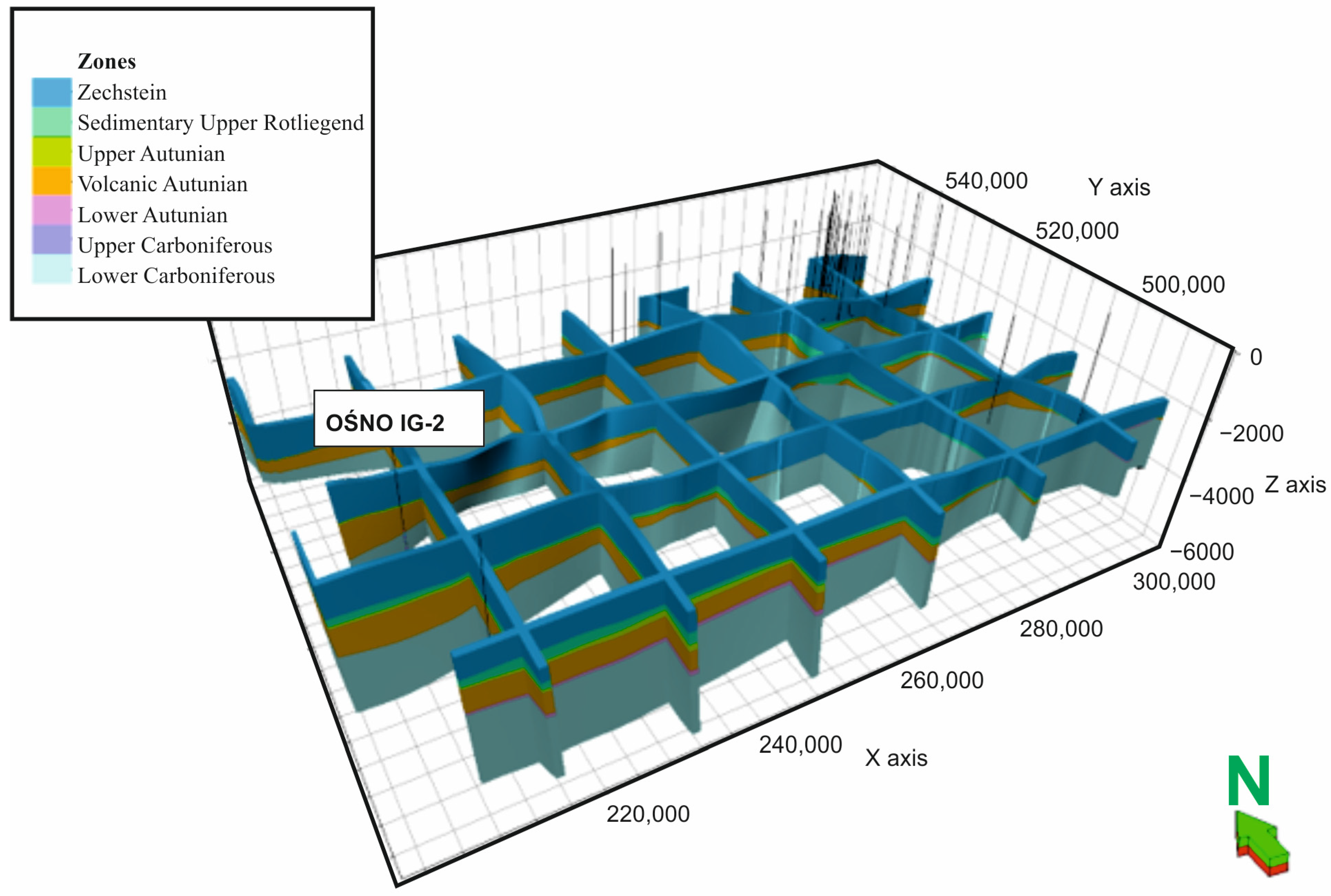
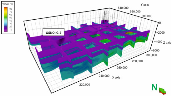
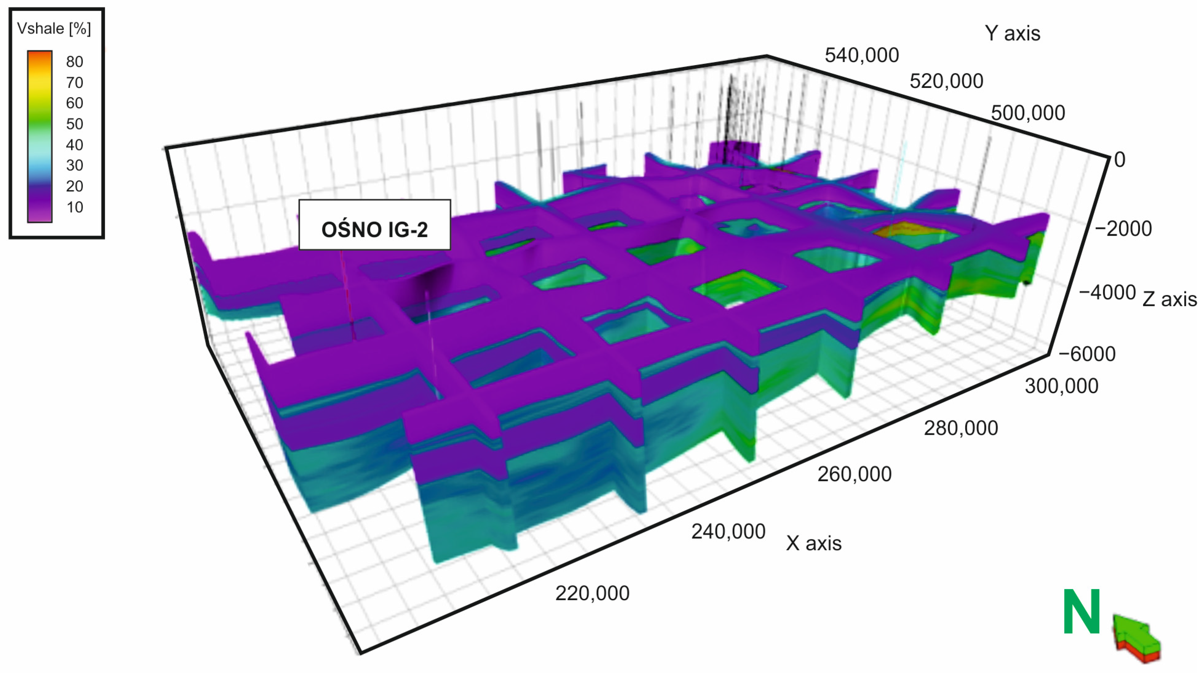
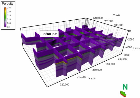
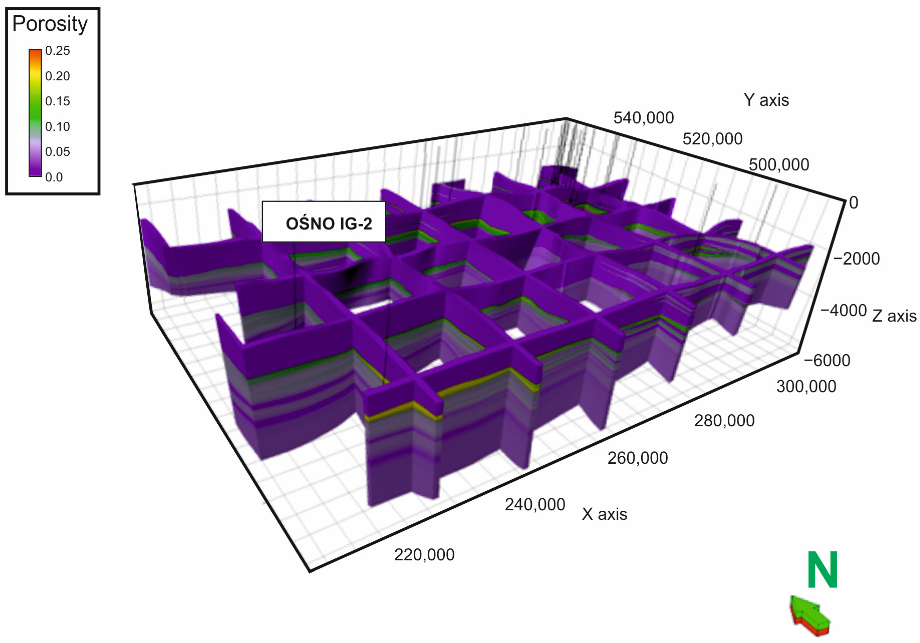
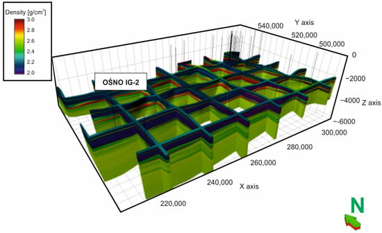
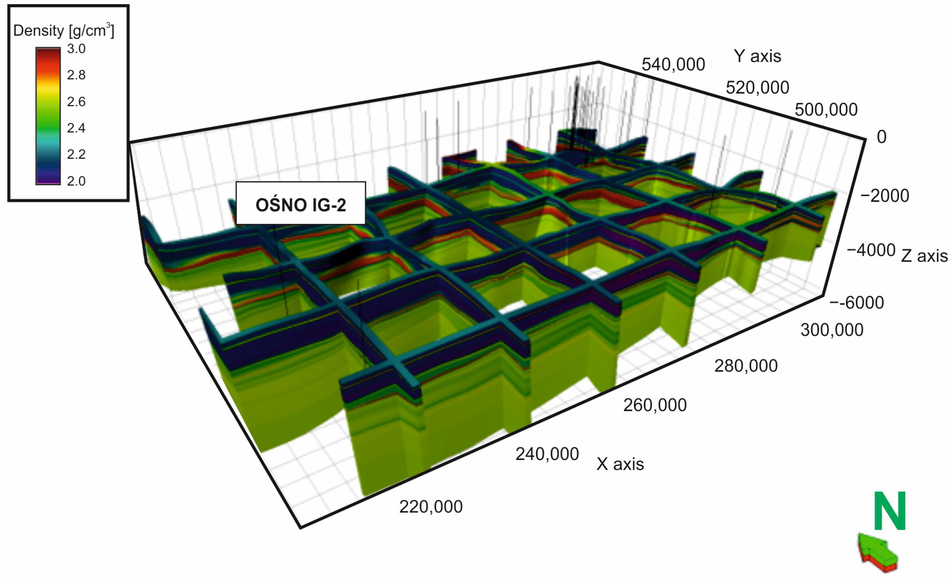
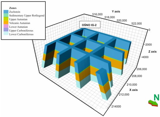
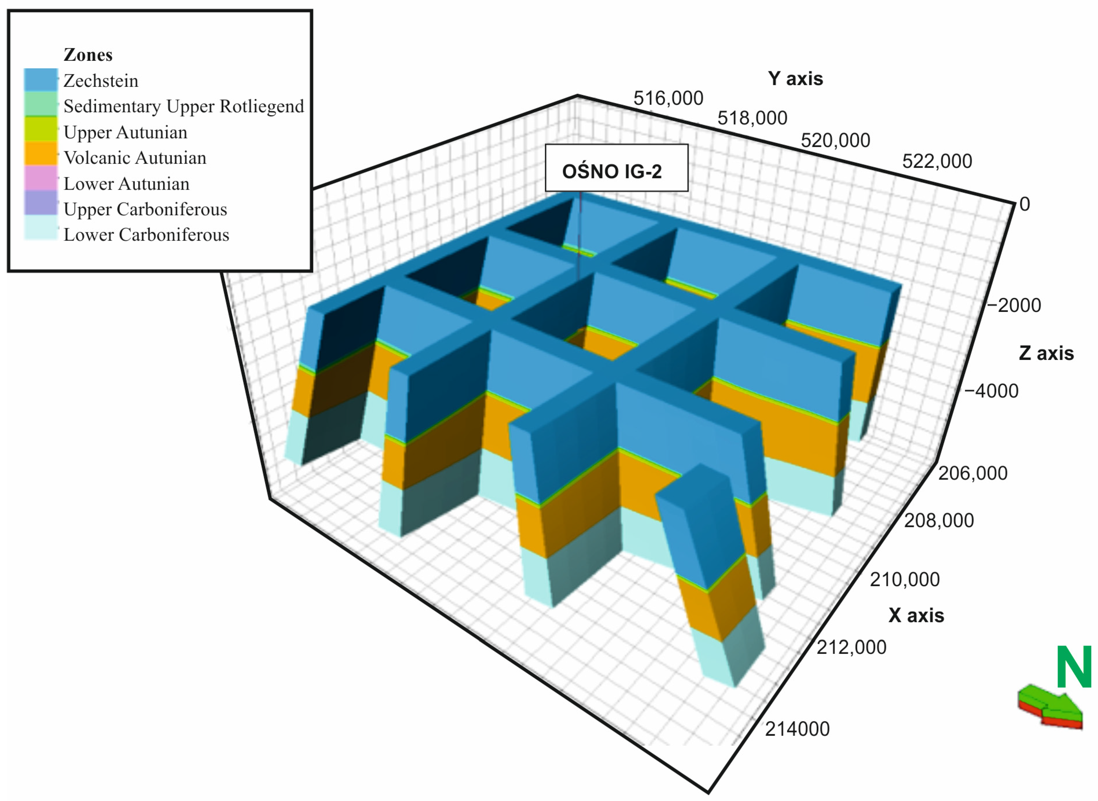
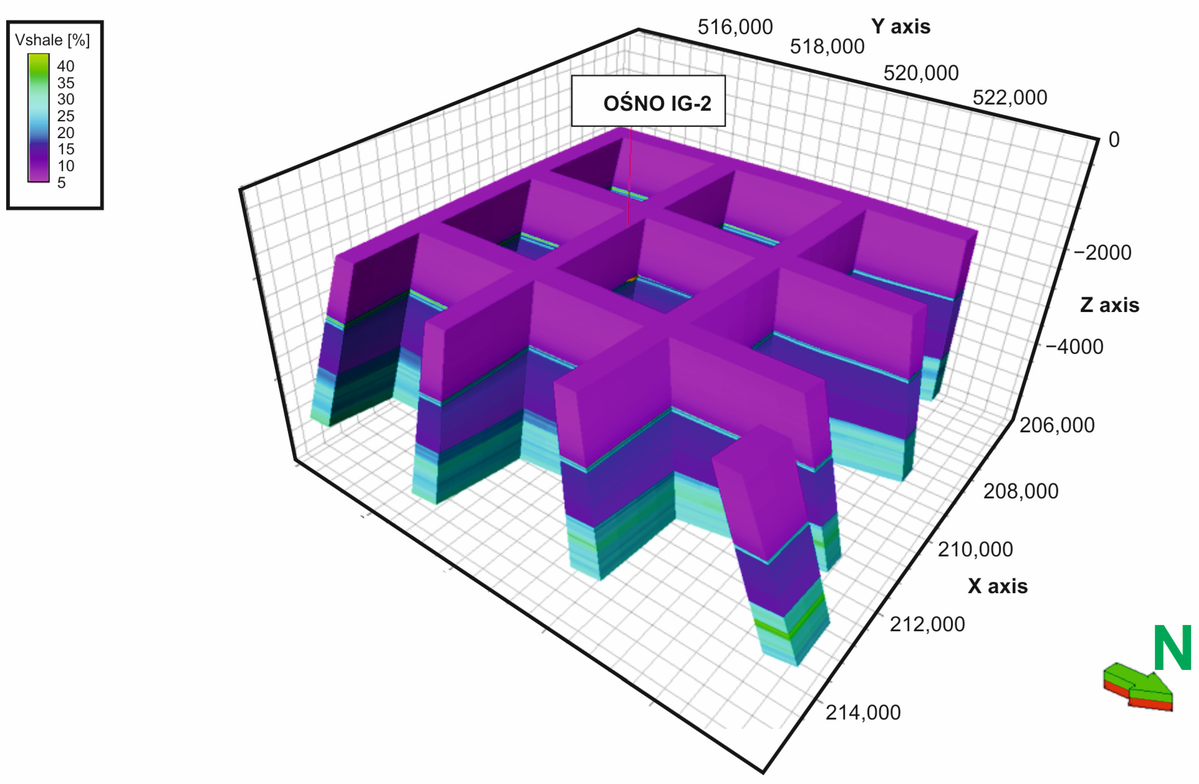
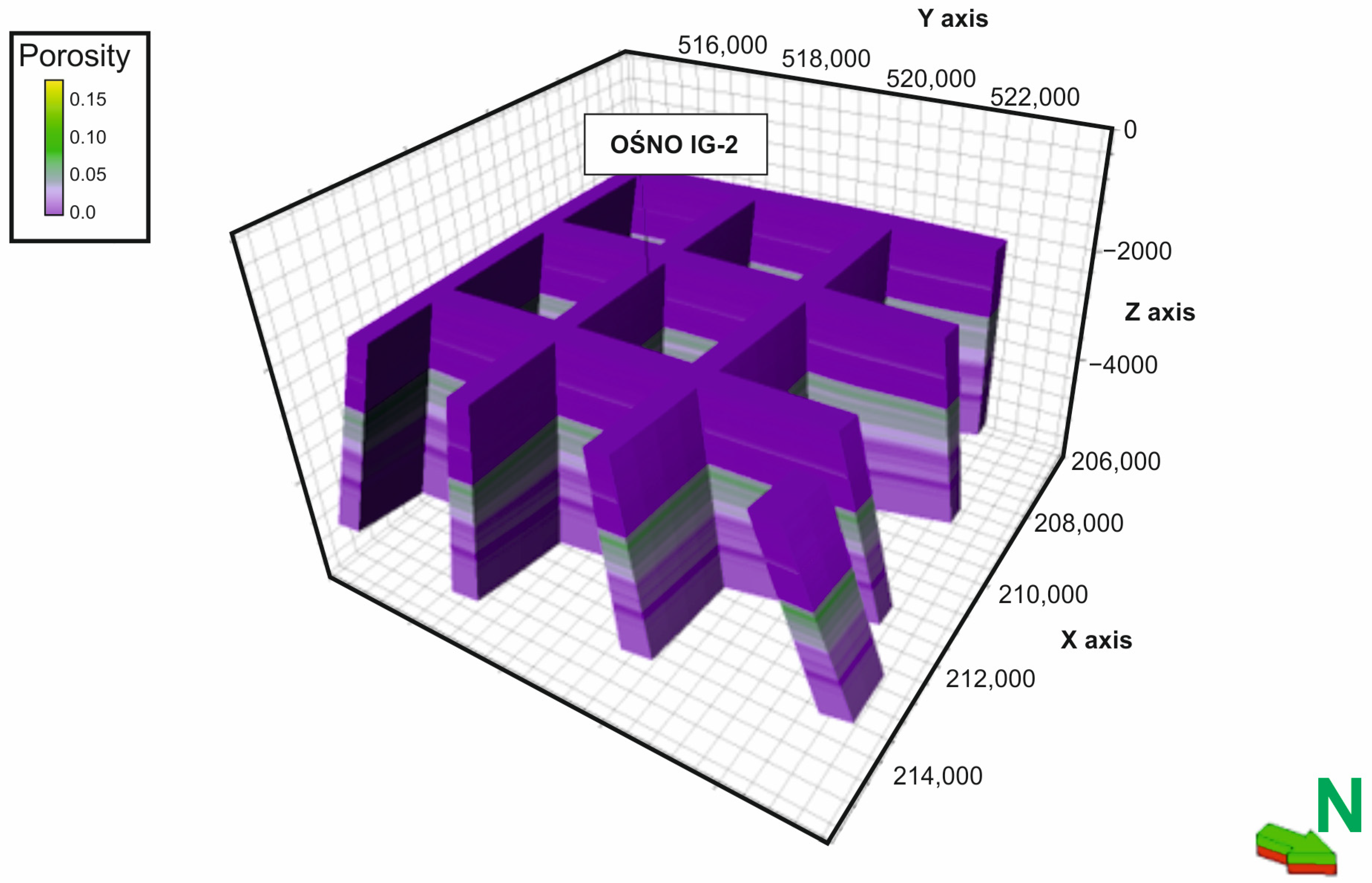
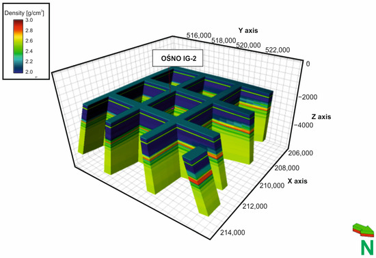
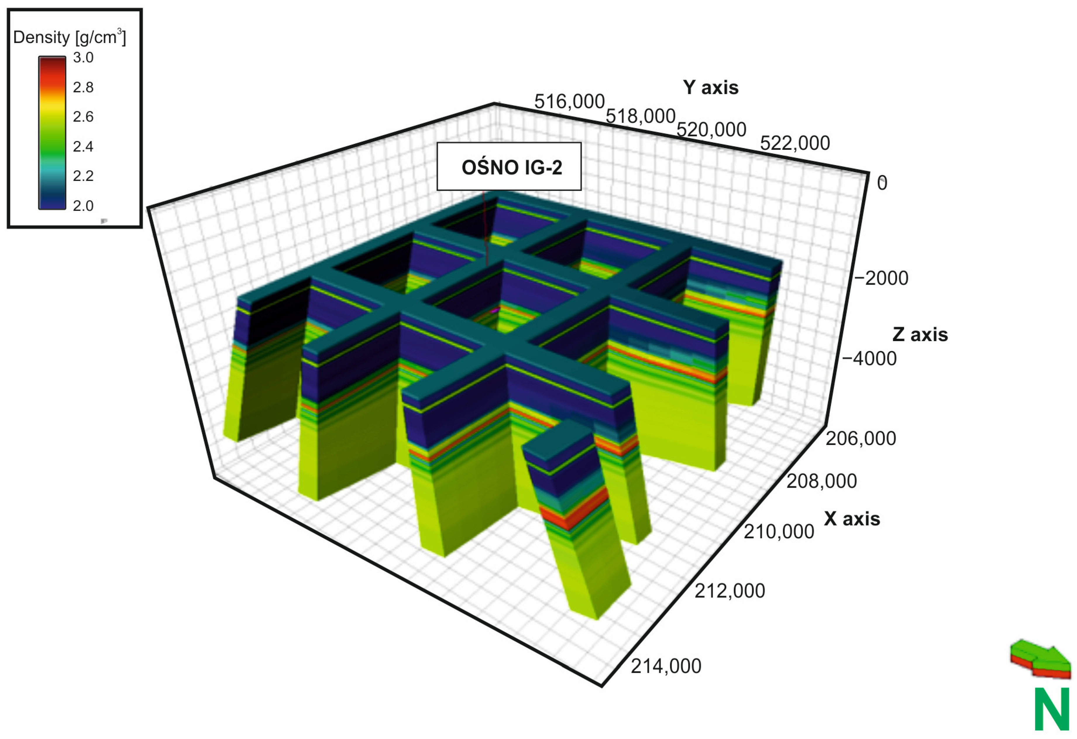
As a result of the conducted modeling, a regional structural (Figure 4) and parametric model (Figure 5, Figure 6 and Figure 7) as well as a local structural (Figure 8) and parametric model (Figure 9, Figure 10 and Figure 11) were obtained. The parametric model includes parameters such as shale content (Figure 5 and Figure 9), porosity (Figure 6 and Figure 10) and density (Figure 7 and Figure 11). For each parameter, a table was prepared showing the corresponding modeling results (Table 2, Table 3, Table 4, Table 5, Table 6 and Table 7).
Figure 4.
Plot diagram of 3D regional structural model.
Figure 5.
Plot diagram of 3D shale volume regional model.
Figure 6.
Plot diagram of 3D porosity regional model.
Figure 7.
Plot diagram of 3D density regional model.
Figure 8.
Plot diagram of 3D local structural model.
Figure 9.
Plot diagram of 3D shale volume local model.
Figure 10.
Plot diagram of 3D porosity local model.
Figure 11.
Plot diagram of 3D density local model.
Table 2.
Statistical parameters of shale volume for the 3D regional model.
Table 3.
Statistical parameters of porosity for the 3D regional model.
Table 4.
Statistical parameters of density for the 3D regional model.
Table 5.
Statistical parameters of shale volume for the 3D local model.
Table 6.
Statistical parameters of porosity for the 3D local model.
Table 7.
Statistical parameters of density for the 3D local model.
Cross-Sections and Maps
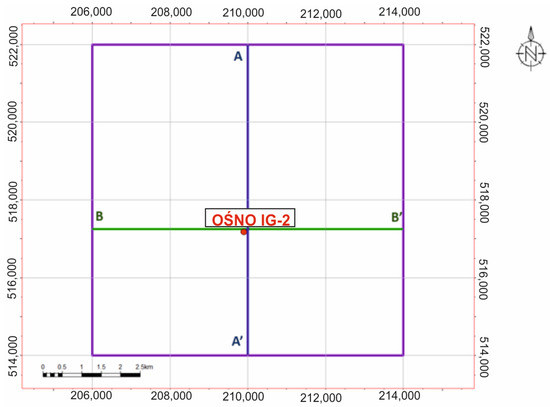
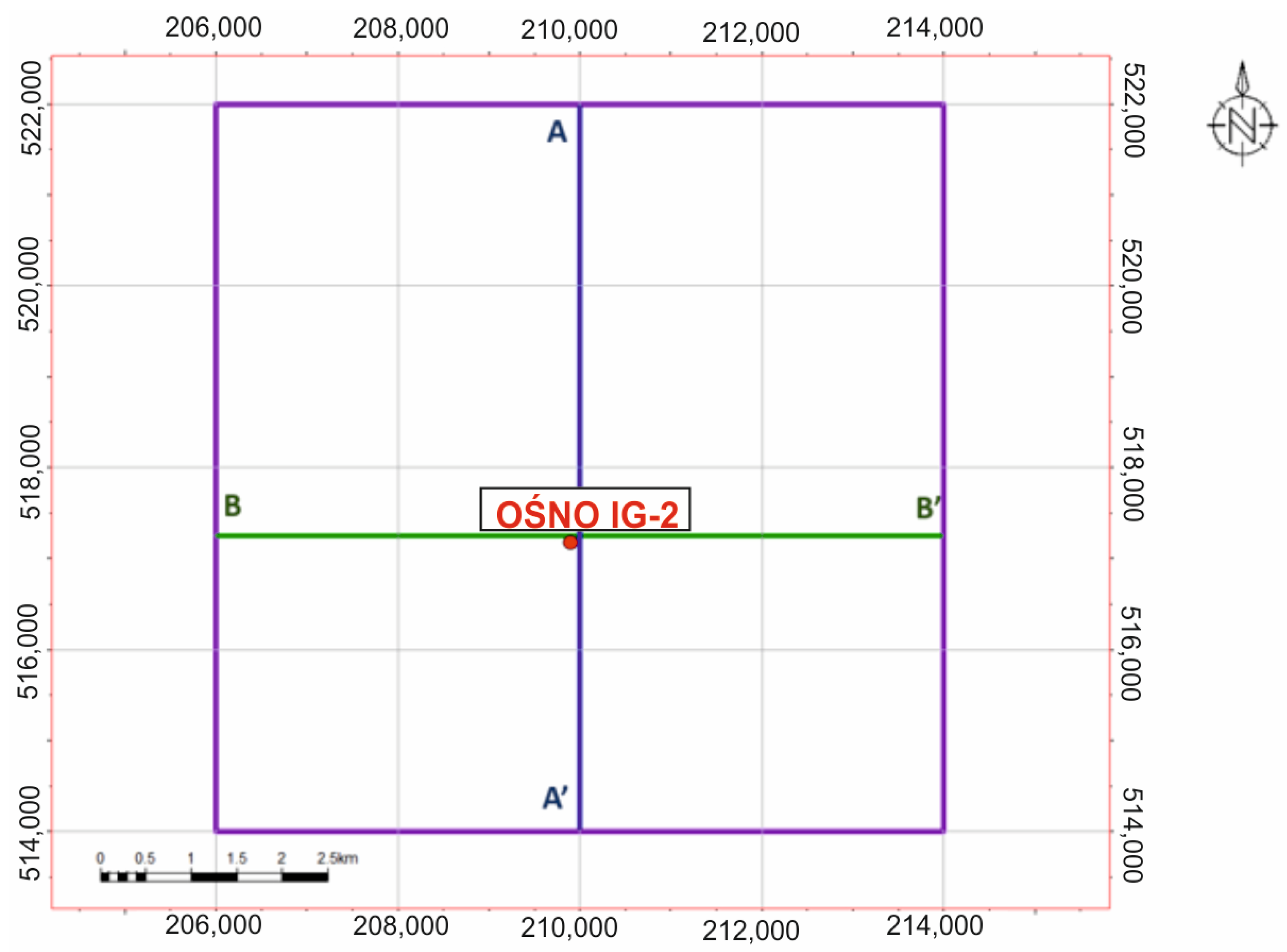
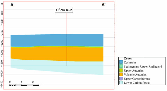
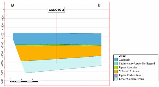
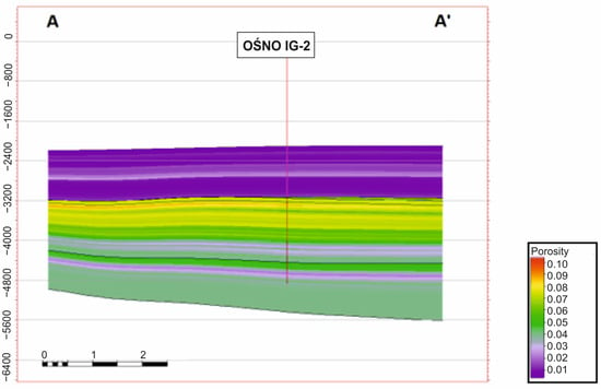
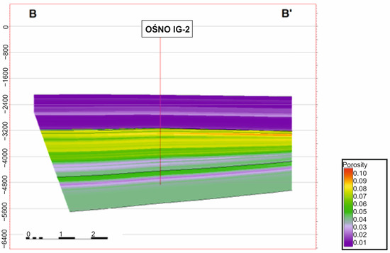
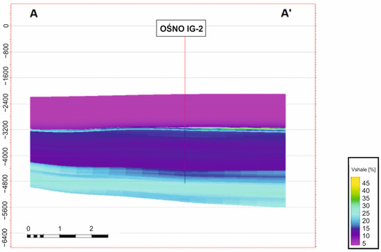
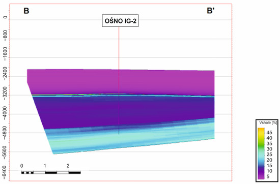
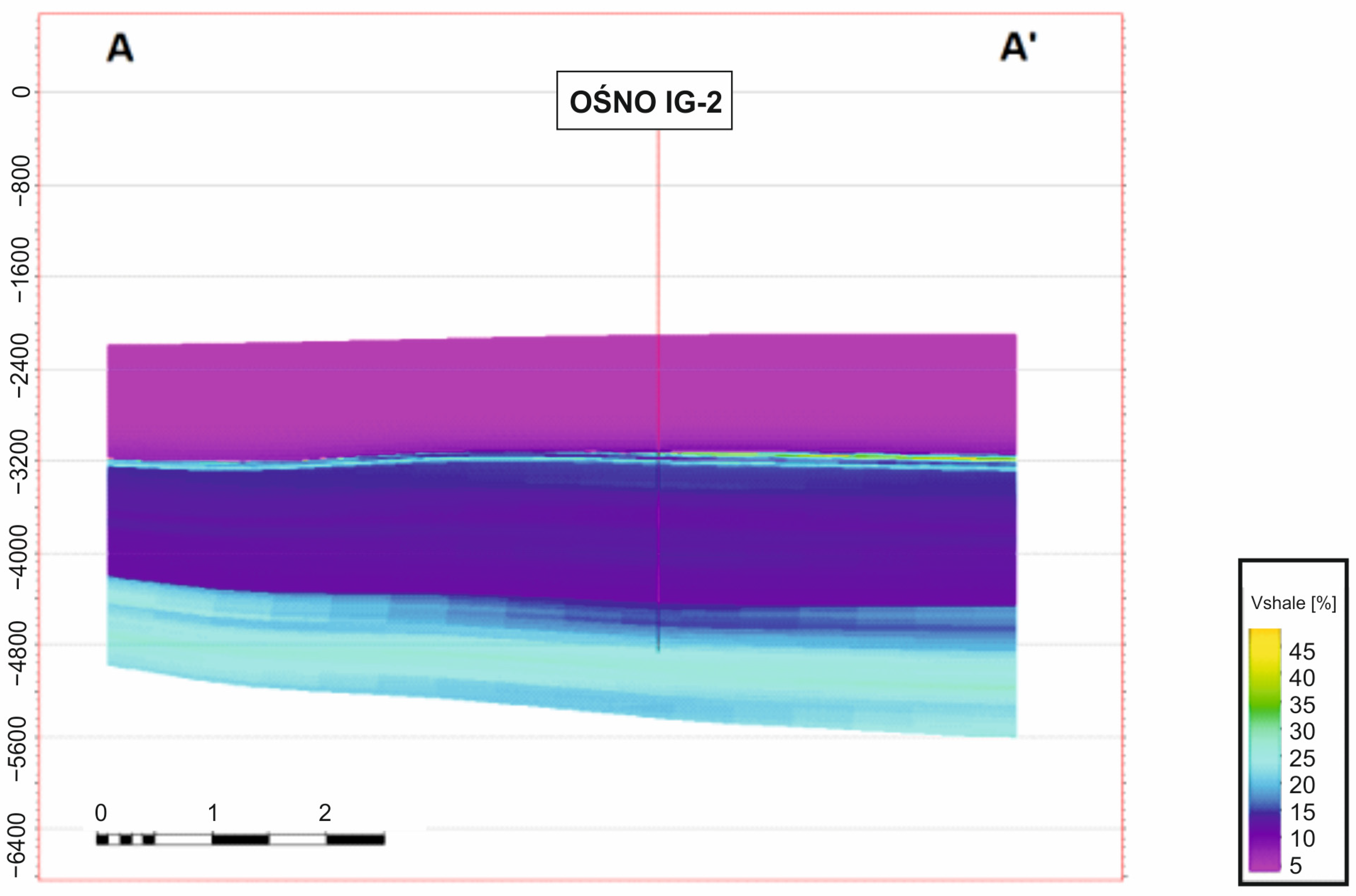
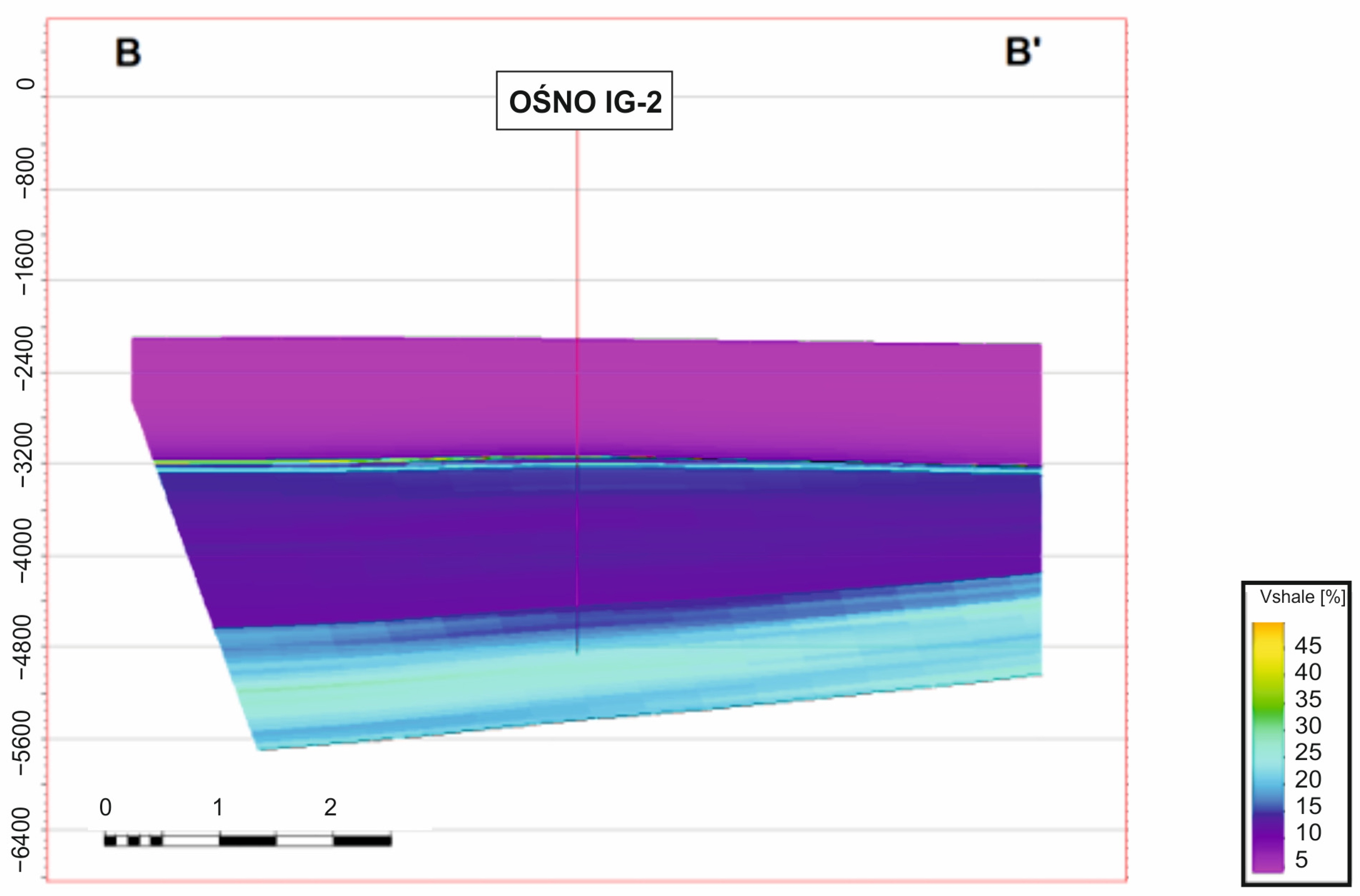
Based on the three-dimensional model, sections along the A-A′ and B-B′ lines were made (Figure 12, Figure 13, Figure 14 and Figure 15) as well as structural and thickness maps (Figure 16 and Figure 17). The cross-sections present the calculation zones and the distribution of parameters: porosity and shale volume content (VSH).
Figure 12.
Location map of local model with cross-section lines A-A′ and B-B′.
Figure 13.
Spatial distribution zones from model along A-A′ and B-B′ lines.
Figure 14.
Spatial distribution porosity from model along A-A′ and B-B′ lines.
Figure 15.
Spatial distribution shale volume content (VSH) from model along A-A′ and B-B′ lines.
Figure 16.
Thickness map of volcanic Autunian deposits.
Figure 17.
Structural map of volcanic Autunian horizon.
5. Discussion
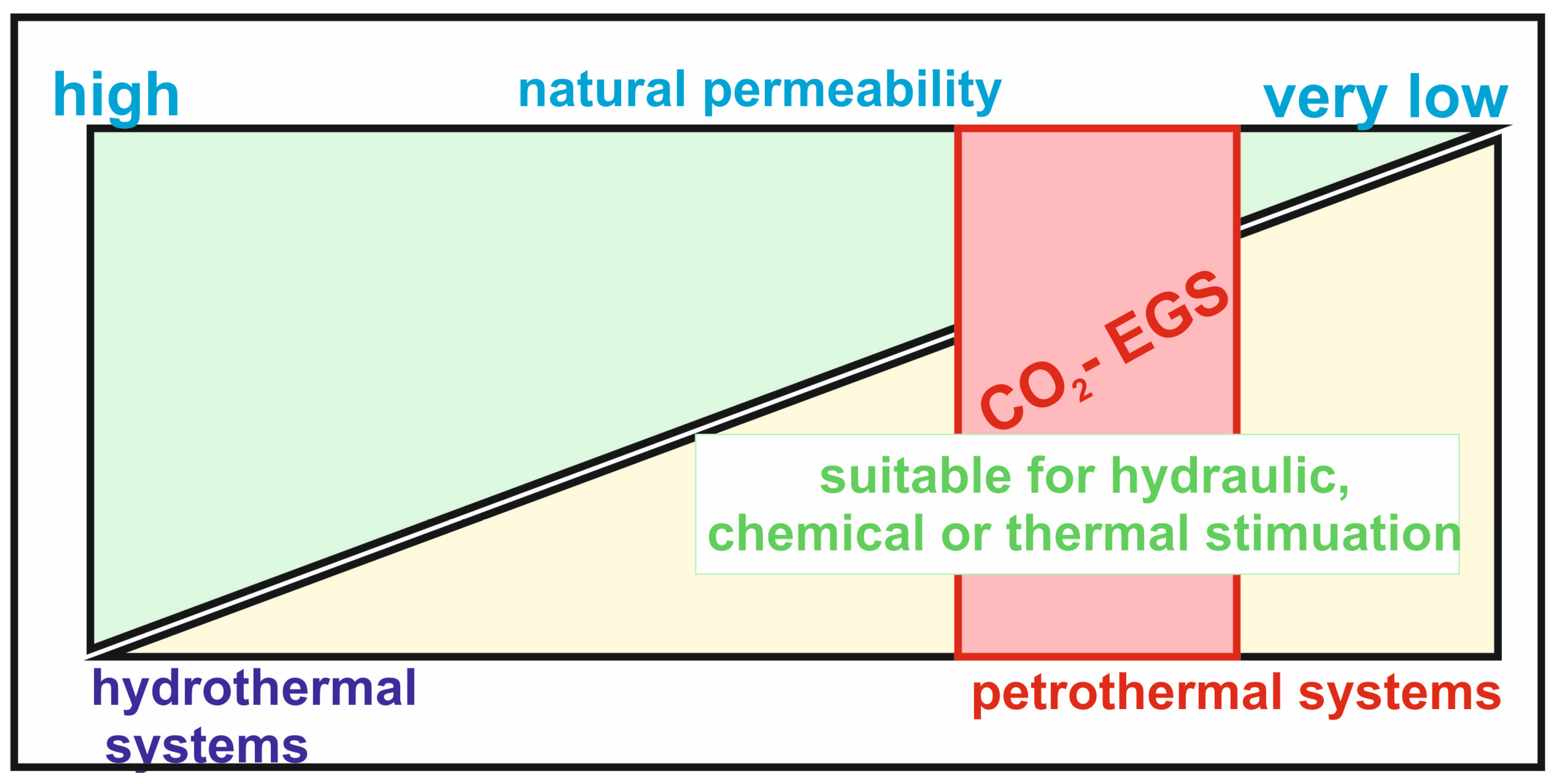
The aim of the geological modeling was to identify reservoir rocks with suitable properties in the Gorzów Block area for a CO2-enhanced geothermal system (CO2-EGS). The efficiency of CO2-EGS strongly depends on geological factors such as structural geometry, as well as the thermal and petrophysical properties of the reservoir. Optimizing these parameters through careful reservoir selection and stimulation is critical for maximizing energy output and extending operational lifetime [27]. In addition to geological criteria, non-geological factors must also be considered, including legal and environmental constraints and the availability of a CO2 source, all of which play a significant role in the site selection process [12]. Identifying a suitable reservoir will have a significant impact on the energy and economic efficiency of the CO2-EGS installation [28]. Petrophysical properties of reservoir rocks play an important role. Suitable formations are characterized by relatively low permeability and porosity, which is important for heat extraction purposes [29,30]; however, in the context of CO2 storage, the presence of rocks with parameters enabling CO2 flow is essential. Therefore, reservoir optimization is crucial in this regard [31,32]. The reservoir rock in a CO2-EGS system should be characterized by parameters that allow both energy extraction from the reservoir zone and the storage of a portion of the CO2 within the formation. It should therefore exhibit relatively low natural permeability to achieve favorable energy performance, while still being sufficiently permeable to enable CO2 storage within the reservoir (Figure 18) [33].
Figure 18.
Place of CO2-EGS systems in the background of the scheme, representing the relationship between the permeability range and hydrothermal and petrothermal systems, respectively (modified after [33]).
In the hydraulic fracturing process, the thickness of the reservoir formation is of key importance and should be at least 300 m [6,34] to enable the creation of an effective fractured reservoir. Equally important is the depth of occurrence of the reservoir rocks—it should be sufficient to ensure adequately high temperatures that support efficient energy production, while also accounting for the costs of reservoir development. Thermal conditions play a crucial role, directly affecting the energy production potential [29]. The reservoir temperature should be around or preferably exceed 150 °C, which under Polish conditions is achievable only at great depths of approximately 5 km. Therefore, the possibility of considering a lower temperature of around 140 °C was also taken into account, which would enable the development of an EGS installation based on shallower than 5 km petrogeothermal reservoirs. The rationale for this decision was the EGS installation in Groß Schönebeck, where the reservoir temperature is approximately 142–143 °C [23].
Considering the high costs of reservoir access at such depths, as well as the need to integrate thermal parameters with other key reservoir properties, this study assumes that the optimal reservoir level—combining petrophysical analyses and thermal conditions—is located at a depth of approximately 4100–4300 m b.g.l., where the temperature is around 145 °C.
This selection was preceded by a detailed analysis of the EGS installation in Groß Schönebeck, which represents the most comparable case to Polish conditions, particularly in terms of reservoir depth, rock types, and temperature distribution. In this case, the reservoir temperature is approximately 142–143 °C, and the system is classified as a petrothermal EGS system [23]. Importantly, thermal conditions in the Groß Schönebeck region, similar to those in the Gorzów area, do not exceed 150 °C, and nevertheless the installation has been successfully implemented and further developed. This provides a key justification for selecting the analyzed reservoir level under Polish conditions.
Additionally, the CO2-EGS reservoir should include an appropriate sealing layer to prevent uncontrolled CO2 migration and leakage.
Taking these criteria into account, the results of geological modeling were analyzed to select the optimal reservoir for a CO2-EGS system in the Gorzów Block area. The conducted geological modeling enables a precise determination of the depth of the EGS system as well as the physical parameters of reservoir rocks, such as porosity, permeability, and shale volume content (VSH). In addition, thermal conditions were considered, including an analysis of the subsurface temperature distribution based on temperature measurements from the Ośno IG-2 well. The heat flux density within the Gorzów Block, according to Szewczyk and Gientka, is approximately 90–100 mW/m2, taking into account palaeoclimatic correction [35]. Based on the analysis of borehole data from the Ośno IG-2 well, the average geothermal gradient along the entire well depth is approximately 30 °C/km. Below a depth of 4000 m, the thermal gradient averages about 3.3 °C/100 m.
The analysis of the obtained results focused primarily on identifying potential reservoir rocks and assessing their suitability for hydraulic fracturing. The highest shale volume (VSH) among the analyzed stratigraphic units was recorded in the sedimentary Upper Rotliegend Formation, ranging from 6.75% to 71.1% (mean 30.3%). The next unit is the Upper Autunian, where VSH varies from 5.64% to 40% (mean 17.9%). However, both formations are characterized by relatively limited thickness—within the local model they do not exceed 80 m. In the Volcanic Autunian, shale volume ranges from 0.28% to 44.9% (mean 12.4%, standard deviation 5.0%), indicating a relatively low clay content, which is favorable for reservoir quality and potential hydraulic fracturing. Regarding bulk density (RHOB), the Volcanic Autunian in the regional model ranges from 2.30 to 2.94 g/cm3 (mean 2.53 g/cm3), while in the local model the mean value is approximately 2.56 g/cm3. After upscaling to the parametric model grid, values range from 2.37 to 2.65 g/cm3 (mean 2.60 g/cm3). Overlying rocks (Upper Autunian) exhibit an average bulk density of approximately 2.51 g/cm3 in the regional model and 2.42 g/cm3 in the local model. For the underlying Lower Carboniferous formation, the average bulk density is approximately 2.64 g/cm3. It should be emphasized, however, that the RHOB model for the Autunian–Carboniferous interval is of low reliability due to sparse data, and the Volcanic Autunian model is based on only two laboratory measurements. Porosity in the Volcanic Autunian ranges from 0 to 29% in the regional model (mean 8%), while in the local model it varies from 0 to 14% (mean 6%). After upscaling, values range from 3% to 9% (mean 6%). The Upper Autunian shows an average porosity of about 7%, whereas the Zechstein formation (mainly rock salt) is characterized by very low porosity (~1%). In the case of the Lower Carboniferous, the average porosity is approximately 4%. Permeability in the Volcanic Autunian within the local model ranges from 0 to 0.5 mD (mean 0.1 mD). However, the most prospective interval in the vicinity of the Ośno IG-2 well exhibits significantly lower permeability, with an average value of approximately 0.003 mD (3 × 10⁻¹⁸ m2). The Upper Autunian shows a mean permeability of 0.27 mD (0.14–0.65 mD), while the Lower Carboniferous is characterized by an average value of approximately 0.004 mD (4 × 10⁻¹⁸ m2). The VSH modeling results indicate generally low shale content in both the Volcanic Autunian and Lower Carboniferous successions at both regional and local scales. In particular, the vicinity of the Ośno IG-2 well is characterized by very low shale volume, suggesting a low content of plastic minerals, which may be favorable for hydraulic fracturing. At the same time, the low porosity and permeability in this area indicate potentially high fracability of the lower part of the Volcanic Autunian.
Structural modeling results show that the stratigraphic framework of the study area is well defined and exhibits significant variability in the thickness of individual units. The top of the Zechstein formation in the Ośno IG-2 well occurs at a depth of 2190 m below ground level, with a thickness of 950–1100 m in the local model. This unit, composed mainly of limestones and dolomites, serves asan effective sealing formation for CO2 migration. A relatively thin Upper Rotliegend succession occurs beneath this unit; however, its distribution is not continuous across the entire local model. It is absent in the north-western part of the study area, whereas in the southern part its thickness reaches 60–80 m (approximately 30 m in the Ośno IG-2 well).
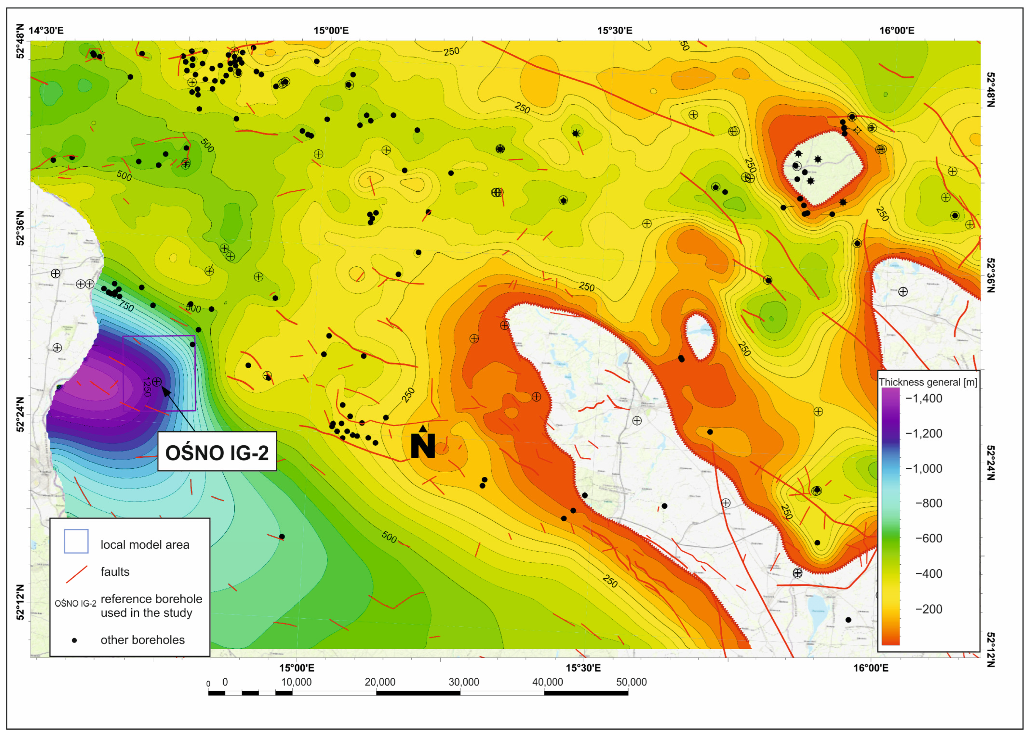
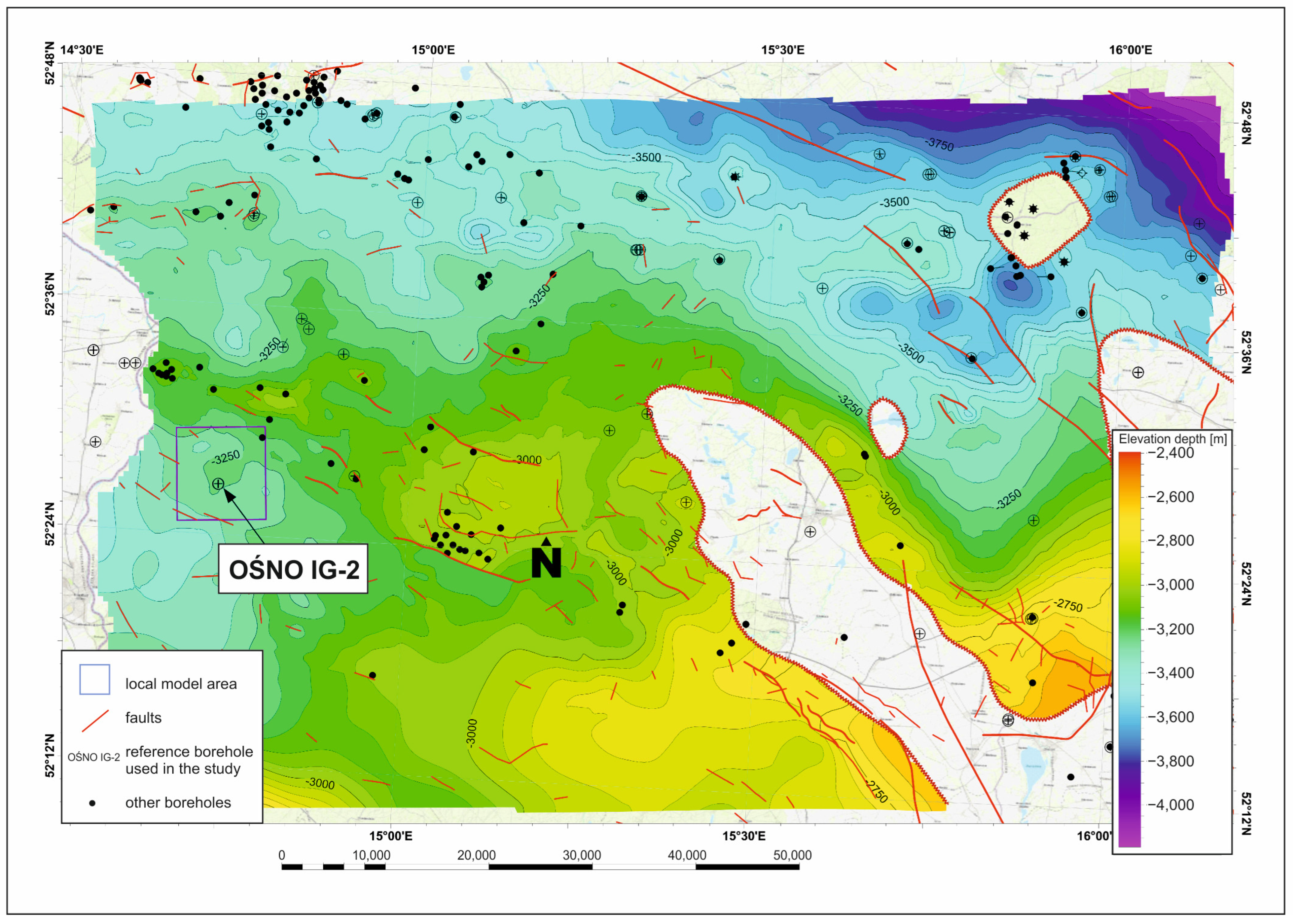
The top of the Upper Autunian in the Ośno IG-2 well is located at 3275.5 m below ground level (−3195.5 m a.s.l.), with a thickness of approximately 60–75 m. The Volcanic Autunian begins at approximately 3330 m below ground level and reaches a thickness of 750–1350 m, increasing towards the west. The Lower Carboniferous occurs from approximately 4530 m below ground level and has a thickness of about 1000 m in the vicinity of the well.
In summary, all analyzed units generally exhibit low porosity, while the most promising geothermal intervals (Volcanic Autunian and Lower Carboniferous) are characterized by both low porosity and low shale content. In particular, the vicinity of the Ośno IG-2 well indicates favorable conditions for hydraulic fracturing in the lower part of the Volcanic Autunian. However, due to limited data, the RHOB model in this interval remains of low reliability.
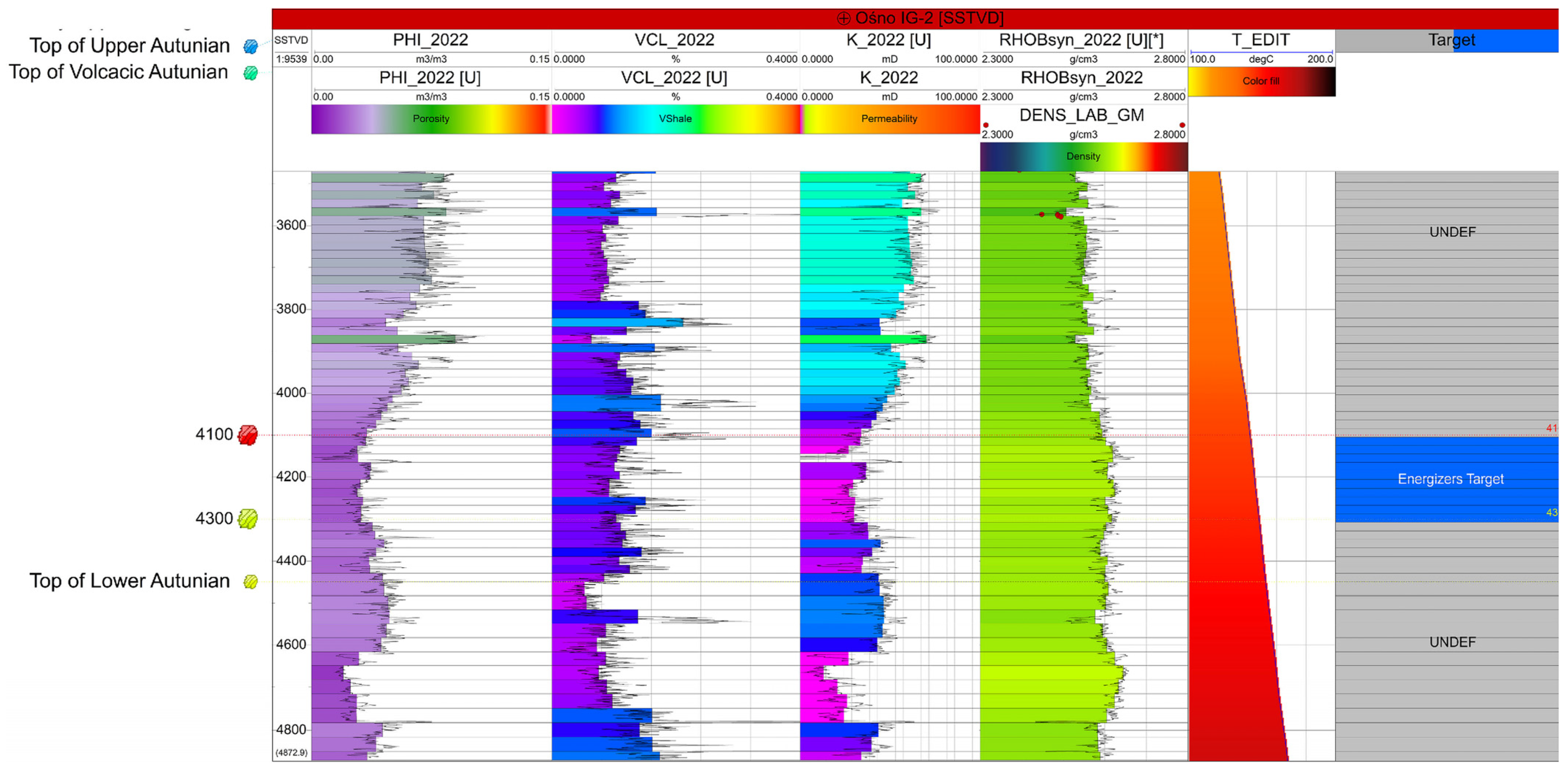
The analysis of the above results indicated that the optimal interval in terms of petrophysical parameters as a reservoir for CO2-EGSis is located at depths between 4100 and 4300 m below ground level. At this depth, volcanic formations of the Lower Permian (Autunian breccias and volcanic rocks) occur. Thermal profiling indicates temperatures at this depth of ca. 145 °C (Figure 19).
Figure 19.
Comparison of geophysical logs with the 1D model within the Ośno-IG2 well. The logs presented include porosity (Track 1), shale volume (VSH—Track 2), density (Track 3), permeability (Track 4), and temperature (Track 5). The interval from 4100 to 4300 m bgl, highlighted in blue, was designated as the potential CO2-EGS reservoir (Track 6).
Table 8 presents statistical data on reservoir parameters for the potential CO2-EGS interval at a depth of 4100–4300 m b.g.l. The average porosity is 0.04, while the clay mineral content (VCL) reaches 0.12. This indicates a moderately low clay fraction, which is favorable for reservoir properties and potential hydraulic fracturing. Permeability is characterized by a very low average value of 0.008 mD, confirming the tight, low-permeability nature of the formation, which requires hydraulic stimulation. Rock density averages 2.59 g/cm3, indicating typical properties of deep volcanic-sedimentary formations. Overall, the analyzed interval is characterized by low porosity and permeability as well as moderate clay content, which, combined with its great depth, makes it a potentially favorable candidate for a CO2-EGS system after appropriate stimulation.
Table 8.
Statistical information about parameters for CO2-EGS reservoir (from 4100 to 4300 m bgl).
The selection of the interval results from an integrated response of petrophysical and thermal parameters. Porosity (ϕ) defines the effective storage and flow capacity, while VSH/VCL is used to exclude clay-rich zones that reduce permeability and degrade reservoir quality [36]. The density log (RHOB) further refines the analysis by identifying low-density zones, which commonly correspond to fractured intervals associated with enhanced permeability [37]. Temperature logs, in turn, constrain the selection to zones with sufficient energy potential, in line with the operational requirements of CO2–geothermal systems [7]. In terms of permeability, the investigated interval should be characterized by relatively low natural matrix permeability, which supports favorable energy performance and system stability, while still maintaining sufficient permeability to enable CO2 storage and circulation within the reservoir, consistent with flow behavior in heterogeneous porous media [33]. Consequently, the interval shown in Figure 19 corresponds to a zone where elevated porosity, low clay content, reduced density, favorable permeability conditions, and elevated temperature co-occur.
This selection was preceded by a detailed analysis of the EGS installation in Groß Schönebeck, which represents the most comparable case to Polish conditions, particularly in terms of reservoir depth, rock types, and temperature distribution. In this case, the reservoir temperature is approximately 142–143 °C, and the system is classified as a petrothermal EGS system [23]. Importantly, thermal conditions in the Groß Schönebeck region, similar to those in the Gorzów area, do not exceed 150 °C; nevertheless, the installation has been implemented. This provides a key justification for selecting the analyzed reservoir interval under Polish conditions and supports the consideration of slightly lower temperatures, which would also enable the development of EGS systems based on shallower petrogeothermal reservoirs.
In Poland, temperatures of approximately 150 °C are typically encountered at depths exceeding 5 km. Considering the high costs of reservoir access at such depths, as well as the need to integrate thermal parameters with other key reservoir properties, this study assumes that the optimal reservoir interval—combining petrophysical analyses and thermal conditions—is located at depths between approximately 4100 and 4300 m b.g.l., where temperatures are around 145 °C. The analysis of the above results indicates that this interval represents the most favorable reservoir zone in terms of petrophysical parameters for CO2-EGS development. At this depth, volcanic formations of the Lower Permian (Autunian breccias and volcanic rocks) occur, which exhibit suitable reservoir characteristics.
6. Conclusions
This study presents a structural–parametric modeling approach for assessing the potential of deep geological formations for the application of CO2-enhanced geothermal systems (CO2-EGSs). The analysis focused on identifying the most suitable reservoir interval based on geological, petrophysical, and thermal parameters. In addition, the study demonstrates the usefulness of structural–parametric modeling as an effective screening tool for identifying prospective CO2-EGS reservoirs in deep volcanic formations.
The modeling results indicate that Lower Permian volcanic rocks (Autunian breccias and volcanic units) represent the most promising reservoir for CO2-EGS applications. The optimal reservoir interval was identified at depths of 4100–4300 m below ground level, where formation temperatures reach approximately 145 °C, providing favorable thermal conditions for geothermal energy production. The investigated interval is characterized by an average porosity of 0.04, low clay mineral content (0.12), and very low permeability (0.008 mD). These parameters indicate the necessity of hydraulic stimulation to enhance reservoir performance. At the same time, the low clay content and elevated formation temperature make this interval particularly suitable for the simultaneous production of geothermal energy and geological storage of CO2. The results therefore confirm that Lower Permian volcanic formations constitute the most prospective target horizon for integrated CO2 sequestration and geothermal energy recovery in the study area.
The obtained results should be regarded as an important stage in the preliminary assessment of the reservoir potential in the context of CO2-enhanced geothermal systems (CO2-EGSs) implementation. The main limitations of this study arise from the level of geological understanding and the limited availability of input data, which are typical for deep reservoir formations. These factors may introduce uncertainties in the model parameters and, consequently, affect the accuracy of the representation of reservoir conditions. Therefore, the presented results should be interpreted as a reliable yet preliminary characterization of the potential of the investigated reservoir.
The presented results provide an important contribution to the assessment of opportunities for expanding the utilization of deep geothermal reservoirs in Poland for sustainable energy production. The identified Lower Permian volcanic formations may constitute a promising target for the implementation of CO2-EGS technology, enabling the simultaneous recovery of geothermal energy and geological sequestration of CO2, the principal greenhouse gas responsible for climate change. Consequently, the proposed approach may support the development of low-carbon energy systems in Poland by enhancing the efficiency of geothermal resource utilization while contributing to national and international greenhouse gas emission reduction goals.
Author Contributions
Conceptualization, A.S.; methodology, A.S., B.P. and G.Z.; software, B.P. and G.Z.; validation, A.S., B.P. and G.Z.; formal analysis, A.S.; investigation, A.S. and B.P.; resources, A.S., B.P. and G.Z.; data curation, G.Z.; writing—original draft preparation, A.S.; writing—review and editing, A.S., B.P. and G.Z.; visualization, B.P. and G.Z.; supervision, A.S.; project administration, A.S.; funding acquisition, A.S. All authors have read and agreed to the published version of the manuscript.
Funding
Research project supported by program “Excellence initiative—research university” for the AGH University of Krakow. This publication was funded by the subsidy granted to the AGH University of Krakow by the Ministry of Science and Higher Education. The research leading to these results has received funding from the Norway Grants 2014–2021 via the National Centre for Research and Development.
Data Availability Statement
The original contributions presented in this study are included in the article. Further inquiries can be directed to the corresponding author.
Conflicts of Interest
The authors declare no conflicts of interest.
Abbreviations
| EGS | Enhanced geothermal system |
| CO2 | Carbon dioxide |
| CO2-EGS | Carbon dioxide-enhanced geothermal system |
| HDR | Hot Dry Rock |
| NW | North-West |
| m b.g.l. | meters below ground level |
| mD | milliDarcy (unit of permeability) |
| g/cm3 | grams per cubic centimeter (unit of density) |
| PHI (ϕ) | Porosity |
| VSH | Volume of shale (shale content) |
| RHOB | Bulk density log |
| k | Permeability |
| q | Heat flux density |
| LCA | Life Cycle Assessment |
| PGI | Polish Geological Institute (Państwowy Instytut Geologiczny) |
| NRI | National Research Institute |
| OŚNO IG-2 | Reference borehole used in the study |
| Rotliegend | Permian sedimentary–volcanic unit |
| Zechstein | Upper Permian evaporitic and carbonate formation |
| CO2 storage | Geological storage of carbon dioxide |
| CO2 circulation | Flow of CO2 in reservoir system |
| EnerGizerS | Research project on CO2-EGS development in Poland |
| Gorzów Block | Study area in NW Poland |
| Groß Schönebeck | Reference EGS site in Germany |
References
- Olasolo, P.; Juárez, M.C.; Morales, M.P.; D’Amico, S.; Nermoen, A. Enhanced geothermal systems (EGS): A review. Renew. Sustain. Energy Rev. 2016, 56, 139–159. [Google Scholar] [CrossRef] [Scilit]
- Lu, S.M. A global review of enhanced geothermal systems (EGS). Renew. Sustain. Energy Rev. 2018, 81, 2902–2921. [Google Scholar] [CrossRef] [Scilit]
- Moska, R.; Labus, K.; Kasza, P.; Moska, A. Geothermal potential of hot dry rock in South-East Baltic Basin countries—A review. Energies 2023, 16, 1542. [Google Scholar] [CrossRef] [Scilit]
- Moeck, I.S. Catalog of geothermal play types based on geologic controls. Renew. Sustain. Energy Rev. 2014, 37, 867–882. [Google Scholar] [CrossRef] [Scilit]
- Brown, D.W. A hot dry rock geothermal energy concept utilizing supercritical CO2 instead of water. In Proceedings of the 25th Workshop on Geothermal Reservoir Engineering; Stanford University: Stanford, CA, USA, 2000. [Google Scholar]
- Pruess, K. Enhanced geothermal systems (EGS) using CO2 as working fluid—A novel approach. Geothermics 2006, 35, 351–367. [Google Scholar] [CrossRef] [Scilit]
- Randolph, J.B.; Saar, M.O. Coupling carbon dioxide sequestration with geothermal energy capture in naturally permeable reservoirs. Geophys. Res. Lett. 2011, 38, L10401. [Google Scholar] [CrossRef] [Scilit]
- Strojny, M.; Gładysz, P.; Andresen, T.; Pająk, L.; Starczewska, M.; Sowiżdżał, A. Environmental impact of enhanced geothermal systems with supercritical carbon dioxide: A comparative life cycle analysis of Polish and Norwegian cases. Energies 2024, 17, 2077. [Google Scholar] [CrossRef] [Scilit]
- Sowiżdżał, A.; Papiernik, B.; Machowski, G.; Hajto, M. Characterization of petrophysical parameters of the Lower Triassic deposits in a prospective location for enhanced geothermal system (central Poland). Geol. Quart. 2013, 57, 729–744. [Google Scholar] [CrossRef] [Scilit]
- Sowiżdżał, A.; Machowski, G.; Krzyżak, A.; Puskarczyk, E.; Krakowska-Madejska, P.; Chmielowska, A. Petrophysical evaluation of the Lower Permian formation as a potential reservoir for CO2-EGS—Case study from NW Poland. J. Clean. Prod. 2022, 379, 134768. [Google Scholar] [CrossRef] [Scilit]
- Sowiżdżał, A.; Starczewska, M.; Papiernik, B. Future technology mix—Enhanced geothermal system (EGS) and carbon capture, utilization, and storage (CCUS)—An overview of selected projects in Poland. Energies 2022, 15, 1112. [Google Scholar] [CrossRef] [Scilit]
- Pająk, L.; Sowiżdżał, A.; Gładysz, P.; Tomaszewska, B.; Miecznik, M.; Andresen, T.; Frengstad, B.S.; Chmielowska, A. Multi-criteria studies and assessment supporting selection of CO2-EGS systems. Energies 2021, 14, 7683. [Google Scholar] [CrossRef] [Scilit]
- Miecznik, M.; Tyszer, M.; Sowiżdżał, A.; Pierzchała, K.; Pająk, L.; Gładysz, P. Numerical modeling of potential CO2-fed enhanced geothermal system in the Gorzów Block, Poland. Energies 2025, 18, 4825. [Google Scholar] [CrossRef] [Scilit]
- Labus, K.; Moska, R.; Labus, M. Potential enhanced geothermal systems in Western Poland—Petrothermal and geochemical issues. Energies 2025, 18, 876. [Google Scholar] [CrossRef] [Scilit]
- Liu, J.; Shao, C.; Yang, B.; Ngata, M.R.; Mwangomba, M.; Josephat, S.; Aminu, M.D. Advances in enhanced geothermal systems: Integrating laboratory, numerical and field insights. Appl. Therm. Eng. 2024, 236, 121395. [Google Scholar] [CrossRef] [Scilit]
- Dadlez, R. Types of local tectonic structures in the Zechstein–Mesozoic complex of northwestern Poland. Biul. Inst. Geol. 1974, 274, 149–177. [Google Scholar]
- Dadlez, R.; Marek, S. General outline of the tectonics of the Zechstein–Mesozoic complex in central and northwestern Poland. Biul. Inst. Geol. 1974, 274, 111–148. [Google Scholar]
- Karnkowski, P.H. Geological structure and evolution of the Gorzów Block (in Polish). Przegl. Geol. 2010, 58, 680–688. [Google Scholar]
- Karnkowski, P.H. Lithostratigraphy of Rotliegend in Wielkopolska (in Polish). Geol. Quart. 1987, 31, 643–672. [Google Scholar]
- Karnkowski, P.H. Rotliegend lithostratigraphy in central Polish Permian Basin. Geol. Quart. 1994, 38, 27–42. [Google Scholar]
- Kiersnowski, H.; Buniak, A. Evolution of the Rotliegend Basin of northwestern Poland. Geol. Quart. 2006, 50, 119–138. [Google Scholar]
- Wagner, R. Stratigraphy and Development of the Zechstein Basin in Poland; Państwowy Instytut Geologiczny: Warsaw, Poland, 1994; Volume 146, pp. 1–71.
- Huenges, E.; Holl, H.G.; Bruhn, D.; Brandt, W.; Saadat, A.; Moeck, I.; Zimmermann, G. Current state of the EGS project Groß Schönebeck. In Proceedings of the European Geothermal Congress 2007, Unterhaching, Germany, 30 May–1 June 2007. [Google Scholar]
- Gajewska, I. Profile of Deep Boreholes of the Geological Institute: Ośno IG-2 (No.57); Wydawnictwa Geologiczne, Polish Geological Instittute: Warsaw, Poland, 1983.
- Central Geological Database. Available online: https://baza.pgi.gov.pl/ (accessed on 10 June 2026).
- Szynkaruk, E. (Ed.) 3D Geological Model of Gorzów Block. Available online: https://geo3d.pgi.gov.pl/en/geomodels (accessed on 15 January 2026).
- Zhao, Y.; Shu, L.; Chen, S.; Zhao, J.; Guo, L. Optimization design of multi-factor combination for EGS power generation. Sustainability 2022, 14, 7001. [Google Scholar] [CrossRef] [Scilit]
- Tagliaferri, M.; Gładysz, P.; Ungar, P.; Strojny, M.; Talluri, L.; Fiaschi, D.; Manfrida, G.; Andresen, T.; Sowiżdżał, A. Techno-economic assessment of the Supercritical Carbon Dioxide Enhanced Geothermal Systems. Sustainability 2022, 14, 16580. [Google Scholar] [CrossRef] [Scilit]
- Wang, C.-L.; Cheng, W.-L.; Nian, Y.-L.; Yang, L.; Han, B.-B.; Liu, M.-H. Simulation of heat extraction from CO2-based EGS. Energy 2018, 142, 157–167. [Google Scholar] [CrossRef] [Scilit]
- Guo, T.; Gong, F.; Wang, X.; Lin, Q.; Qu, Z.; Zhang, W. Performance of EGS in fractured reservoirs with CO2 as working fluid. Appl. Therm. Eng. 2019, 152, 215–230. [Google Scholar] [CrossRef] [Scilit]
- Dalsania, K.P.; Sircar, A. Advancing enhanced geothermal systems: Novel strategies for sustainable energy extraction and risk mitigation. Unconv. Resour. 2026, 9, 100272. [Google Scholar] [CrossRef] [Scilit]
- Jung, H.B.; Carroll, K.C.; Kabilan, S.; Heldebrant, D.J.; Hoyt, D.; Zhong, L.; Varga, T.; Stephens, S.; Adams, L.; Bonneville, A.; et al. Stimuli-responsive hydraulic fracturing fluids. Green Chem. 2015, 17, 2799–2812. [Google Scholar] [CrossRef] [Scilit]
- Blöcher, G.; Peters, E.; Kluge, C.; Ilangovan, N.; Bruhn, D.; Nick, H. Report on Stimulation Technologies for Geothermal Reservoirs; GFZ: Potsdam, Germany, 2016. [Google Scholar]
- Gładysz, P.; Sowiżdżał, A.; Miecznik, M.; Pająk, L. Carbon dioxide-enhanced geothermal systems for heat and electricity production: Energy and economic analyses for central Poland. Energy Convers. Manag. 2020, 220, 113142. [Google Scholar] [CrossRef] [Scilit]
- Szewczyk, J.; Gientka, D. Terrestrial heat flow density in Poland. Geol. Quart. 2009, 53, 125–140. [Google Scholar]
- Nazemi, A.; Dashtgard, S.E.; Amarante, F.B.d.; Hassanzadeh, H.; La Croix, A.D. Geological screening for CO2 storage. Greenhouse Gases Sci. Technol. 2025, 15, 1–20. [Google Scholar] [CrossRef] [Scilit]
- Behzadi, S.S.; Alvarado, V.; Mallick, S. CO2 saturation and seismic response. Environ. Sci. Technol. 2011, 45, 101–108. [Google Scholar] [CrossRef] [Scilit] [PubMed]

Disclaimer/Publisher’s Note: The statements, opinions and data contained in all publications are solely those of the individual author(s) and contributor(s) and not of MDPI and/or the editor(s). MDPI and/or the editor(s) disclaim responsibility for any injury to people or property resulting from any ideas, methods, instructions or products referred to in the content. |
© 2026 by the authors. Licensee MDPI, Basel, Switzerland. This article is an open access article distributed under the terms and conditions of the Creative Commons Attribution (CC BY) license.