


Abstract
Maintaining a conductive network is essential for achieving high energy density and long-term reliability in lithium-ion batteries. However, its stability is often compromised by structural non-uniformity, and under high-voltage operation, by the oxidative degradation of carbon-based conductive additives. To address these issues, we propose a composite cathode design that combines multi-component electrophoretic deposition (EPD) with a chemically stable Ti4O7 conductive oxide. The EPD conditions were systematically investigated, and an applied voltage of 100 V was identified as the standard voltage for controlling electrode loading while avoiding cracking and delamination under severe deposition conditions. The electrochemical performance of the EPD-derived electrodes depended strongly on the Ti4O7 content in the initial EPD suspension. Ti-0 and Ti-1, prepared from suspensions containing 0 and 1 wt% Ti4O7, respectively, maintained stable capacity delivery over a wide loading range, with areal capacities in good agreement with the theoretical values. In contrast, Ti-5, prepared from a suspension containing 5 wt% Ti4O7, exhibited significant capacity degradation and failed under high-loading conditions. High-voltage cycling over 50 cycles and impedance analysis further showed that Ti-1 exhibited better cycling behavior than Ti-0, with less pronounced resistance growth, whereas Ti-5 displayed poor cycling performance. These results suggest that multi-component EPD with an appropriate amount of Ti4O7 can provide a balanced hybrid conductive network for improving the relative high-voltage cycling behavior of cathodes within the tested condition.
1. Introduction
Global trends toward decarbonization and the electrification of transportation systems are driving the rapid expansion of electric vehicles (EVs) and large-scale energy storage systems (ESSs). Accordingly, lithium-ion batteries (LIBs) have established themselves as a core technology for realizing carbon neutrality [1]. With this market expansion and the diversification of application environments, there is a continuous demand for LIBs to operate at higher voltages for increased energy density and to possess stable long-term reliability [2].
Recent studies on advanced lithium-battery systems have emphasized that electrode-level transport, interfacial stability, and microstructural control are critical for achieving high energy density and stable operation. In particular, thick or high-loading electrodes require continuous electron pathways and accessible ion-transport channels to avoid non-uniform reaction distribution and premature capacity loss [3]. In addition, recent studies on lithium-battery interfaces and functional components have shown that interfacial side reactions and unstable transport pathways remain major obstacles to durable high-voltage or high-energy operation [4]. These findings indicate that electrode-fabrication strategies must simultaneously consider active-material utilization, conductive-network stability, and microstructural uniformity. In particular, under high-voltage and high-loading conditions, long cycle life depends critically on maintaining a continuous conductive network [5,6,7].
The loss of this electrical continuity can be broadly attributed to two factors: physical disruption arising from processing limitations and chemical degradation originating from material instability. First, physical disruptions in electrical continuity can arise from processing-related limitations. Conventional slurry-based coating processes, including slurry casting and slot-die coating, are highly established for lithium-ion battery electrode manufacturing. However, when thick or compositionally complex electrodes are targeted, simultaneous control of electrode loading, thickness, and multi-component distribution can become increasingly challenging [8]. In particular, during the drying process after coating, relatively lighter conductive additives and binders can migrate toward the electrode surface along the solvent evaporation pathway, resulting in structural non-uniformity [9]. These effects may become more pronounced as the electrode loading increases, causing compositional non-uniformity along the electrode depth and ultimately hindering electrical continuity. Second, chemical degradation of the conductive network stems from material instabilities. Widely used carbon-based conductive additives (e.g., carbon black and graphite) are thermodynamically unstable under the operating potentials of LIB cathodes. During charge and discharge, carbon materials undergo side reactions with the electrolyte, forming irreversible films such as a cathode electrolyte interphase (CEI) on the surface [10,11,12], or they undergo electrochemical oxidation and are consumed as CO and CO2 gases [13,14]. In addition, the intercalation of electrolyte anions such as PF6− can induce volume expansion and exfoliation of the carbon lattice, further damaging its structure [10,15,16]. As a result, high-voltage operation can accelerate degradation of the conductive network, leading to increased internal resistance and shortened battery life.
Various advanced deposition strategies have been explored for functional multi-component oxide films, including approaches that enable precise control over composition, interface quality, and microstructure [17,18]. These methods provide important advantages for designing functional oxide layers and well-defined interfaces. However, battery composite cathodes require the integration of active material particles, conductive additives, and polymeric components over relatively large electrode areas. In this context, electrophoretic deposition (EPD) is attractive as a solution-based and electrically driven process because it can deposit heterogeneous particulate components onto a current collector while allowing the deposited mass and thickness to be tuned by the applied electric field and deposition time.
To address the need for both process-level control of electrode structure and material-level stabilization of the conductive network, the EPD and Magnéli phase titanium oxide (Ti4O7) can therefore be combined as a practical strategy for fabricating high-voltage composite cathodes. Specifically, EPD enables direct particle deposition onto a substrate under an electric field, allowing for the precise control of electrode thickness and loading [8] while also providing strong physical adhesion to the substrate [19,20,21,22,23,24,25,26]. In addition, the electric-field-driven deposition mechanism can mitigate the localized concentration phenomena that occur during drying in conventional coating processes [27,28]. Meanwhile, Ti4O7 exhibits high electronic conductivity, reported to exceed 103 S/cm, owing to its crystallographic shear structure and mixed-valence state (Ti3+/Ti4+) [29,30,31]. Its oxide-based chemical stability also makes it an attractive candidate for partially replacing carbon conductive additives in high-voltage cathodes.
However, despite these advantages, multi-component EPD involving the co-deposition of heterogeneous particles with different densities, dielectric constants, and surface charge characteristics requires complex process control [32,33,34]. Unlike single-particle deposition, multi-component suspensions can exhibit differences in deposition rate due to particle-dependent surface charge (zeta potential) and electrophoretic mobility [35]. Furthermore, density-dependent sedimentation may generate vertical concentration gradients in the suspension over time, which can lead to compositional non-uniformity in the deposited electrode [36]. Accordingly, although EPD has been widely explored for energy-storage electrodes, experimental studies that directly correlate co-deposition behavior, resulting electrode composition, and electrochemical performance in multi-component cathode systems remain limited. Therefore, a systematic analysis of how process parameters affect the deposited structure and final electrochemical behavior is needed to establish the reliability of the multi-component EPD process.
This study examines the applicability of multi-component EPD for fabricating composite cathodes and clarifies how process conditions influence electrode structure and electrochemical performance. Specifically, the effects of conductive additive composition, applied voltage, and deposition time on the physical properties of the deposited layer are quantitatively analyzed, and the influence of Ti4O7 incorporation on the electrochemical behavior of the resulting cells is comparatively evaluated. This work provides practical process and material insights into the design of structurally uniform and electrochemically stable EPD-derived composite electrodes.
2. Materials and Methods
2.1. Electrode Fabrication via EPD
The EPD suspension was prepared using isopropyl alcohol (IPA, 99.5%, Sigma-Aldrich, St. Louis, MO, USA) as the solvent. Li[Ni0.62Co0.2Mn0.18]O2 (NCM622, 4–7 μm, Rov Co., Incheon, Republic of Korea) was used as the cathode active material, while carbon black (50% compressed, 99.9+%, Alfa Aesar, Ward Hill, MA, USA) and conductive oxide Ti4O7 (<2 μm, Handan Muhua New Materials Co., Ltd., Handan, China) were used as conductive additives. Additionally, MgCl2 (Sigma-Aldrich, USA) and the polymeric binder polyvinylpyrrolidone (PVP, MW: 360,000, Thermo Fisher Scientific, Swindon, UK) were used as additives to induce surface charges on the particles within the suspension [26,37]. The suspension was prepared by first completely dissolving MgCl2 and PVP in IPA at concentrations of 0.2 g/L and 0.5 g/L, respectively, followed by the addition of the active material and conductive additive powders. The total solid content was fixed at 5 g/L. To evaluate the effect of conductive additive composition, the weight ratio of the solid components (NCM622:carbon black: Ti4O7) was set to 90:10:0, 90:9:1, and 90:5:5, and the corresponding suspensions/electrodes were hereafter denoted as Ti-0, Ti-1, and Ti-5, respectively. Subsequently, to ensure uniform dispersion, the mixture was ultrasonicated (5510, Branson Ultrasonics, Brookfield, CT, USA) for 30 min and then magnetically stirred (PC-4200, Corning Inc., Corning, NY, USA) for 60 min.
A schematic diagram of the EPD system is shown in Figure S1. The deposition cell was assembled with an Al foil (15 μm, UACJ, Tokyo, Japan) as the working electrode and a SUS304 foil (10 μm, UACJ, Japan) as the counter electrode, separated by a 1 cm gap. The deposition area was fixed at 2 cm × 3 cm. Constant voltages of 60, 100, and 200 V were applied, and the deposition time was adjusted in the range of 2–20 min. To suppress particle sedimentation during prolonged deposition and to maintain suspension homogeneity, the deposition was temporarily paused every 5 min, and the suspension was briefly re-dispersed by stirring before resuming the deposition. To ensure the reproducibility of the deposited mass and thickness data, experiments for each condition were repeated at least three times, and the results are presented as mean ± standard deviation. The deposited electrodes were naturally dried at room temperature for 12 h to primarily remove the solvent, and then dried in an oven (DS-520MP, Daewon Science, Bucheon, Republic of Korea) at 110 °C for 12 h to completely remove residual moisture. The mass loading was calculated from the weight difference of the Al foil before and after deposition and drying, normalized by the defined deposition area.
2.2. Electrode Microstructural Analysis
To analyze the microstructural characteristics of the electrodes prepared under different EPD conditions (conductive additive composition, applied voltage, and deposition time), a field-emission scanning electron microscope (FE-SEM, Mira3, TESCAN, Brno, Czech Republic) was used. Top-view observations were first performed to compare the surface cracks and defect patterns formed under different deposition conditions. Subsequently, to investigate the elemental distribution, the electrodes were calendered under the same condition used for electrochemical evaluation (Section 2.3) and then ion-milled (IM-4000, HITACHI, Tokyo, Japan) to prepare flat cross-sections. On these prepared cross-sections, elemental mapping was performed using an energy-dispersive X-ray spectrometer (EDS, 51-XMZ1004, Oxford Instruments, Abingdon, UK) to examine the spatial distribution of the major constituent elements (Ni, C, and Ti). Furthermore, additional quantitative EDS analysis was conducted to determine the compositional ratio (wt%) of each deposited material, from which the phase ratio of NCM622:carbon:Ti4O7 in the deposited electrodes was estimated based on the elemental compositions and the nominal stoichiometries of the constituent phases.
To further quantify the spatial distribution of Ti-containing regions, grid-based image analysis was performed using the Ti elemental maps with ImageJ software (version 1.54k, National Institutes of Health, Bethesda, MD, USA). Each Ti map was divided into 5 × 5 subregions, and the Ti-covered area fraction was calculated in each subregion using the same thresholding procedure. The average Ti area fraction was used to compare the overall Ti-containing area, while the standard deviation among the 25 subregions was used as an indicator of spatial heterogeneity in the Ti distribution. The electrode porosity was estimated from the measured electrode density and the theoretical density of the solid components. The electrode density was calculated from the areal mass loading and electrode thickness, while the theoretical solid density was estimated from the final NCM622:carbon:Ti4O7 phase ratio obtained by quantitative EDS analysis. The porosity was calculated using the following equation: Porosity (%) = [1 − electrode density/solid density] × 100.
2.3. Cell Assembly and Electrochemical Evaluation
To evaluate the electrochemical properties, the as-deposited electrodes were calendered in two successive passes, with the roll gap set to 50% of the measured electrode thickness before each pass, to enhance the physical adhesion and electrical contact between the deposited particles and the current collector. The electrodes were then punched into 14 mm diameter disks to serve as working electrodes and assembled into CR2032-type coin cells (Hohsen Corporation, Tokyo, Japan). Lithium metal foil (99.9%, 10 μm, MTI Corporation, Richmond, CA, USA) and a Celgard 2400 membrane (Celgard LLC, Charlotte, NC, USA) were used as the counter electrode and separator, respectively. The electrolyte consisted of 1 M lithium hexafluorophosphate (LiPF6) dissolved in a mixture of ethylene carbonate and ethyl methyl carbonate (EC/EMC, 3:7 vol.%) (Dongwha Electrolyte, Seoul, Republic of Korea). All cells were assembled in an argon-filled glove box (O2, H2O < 0.1 ppm, MBraun, Garching, Germany).
For the initial activation, the cells were cycled three times at 0.1 C within the voltage range of 2.5–4.3 V (vs. Li/Li+). The C-rate was calculated based on a nominal specific capacity of NCM622 of 170 mAh g−1. The areal capacity corresponding to the electrode loading was determined based on the discharge capacity of the third cycle. The high-voltage cycle life was evaluated by performing 50 charge/discharge cycles at 0.5 C in the range of 2.5–4.5 V. Electrochemical impedance spectroscopy (EIS) was conducted to analyze the changes in the internal resistance of the electrodes. The EIS measurements were performed before and after the cycle tests at a 50% state of charge (SoC 50) under open-circuit voltage (OCV) conditions, over a frequency range from 1 MHz to 0.1 Hz with an AC amplitude of 10 mVrms. Before each EIS measurement, the cells were rested at SoC 50 for 1 h to ensure a stabilized OCV condition. At least three cells were tested for each condition. The electrochemical trends discussed in this study were reproducibly observed across repeated cells, and representative data are shown in the main figures. All electrochemical measurements were carried out at room temperature (25 °C). The charge/discharge tests were performed using a multichannel potentiostat/galvanostat system (BCS; Biologic Co., Seyssinet-Pariset, France) equipped with EC-Lab software, and the AC impedance analysis was conducted using a Solartron 1470E multichannel potentiostat coupled with a Solartron 1455A frequency response analyzer (AMETEK Scientific Instruments, Wokingham, UK) using ZView software.
3. Results
3.1. Effect of EPD Parameters on Co-Deposition Behavior and Microstructure
The deposition behavior and physical structure formation of electrodes were investigated as a function of process conditions in a multi-component EPD system containing the active material (NCM622) and heterogeneous conductive additives (carbon black and Ti4O7). To this end, changes in the electrode mass loading, thickness, and density were evaluated according to the applied voltage, deposition time, and conductive additive condition (Ti-0, Ti-1, and Ti-5). Given the nature of the EPD process, the actual composition of the deposited electrode may differ from the initial suspension composition due to differences in particle mobility. Therefore, the subsequent results were interpreted primarily in terms of overall trends in electrode characteristics as a function of conductive additive composition, rather than absolute compositional values.
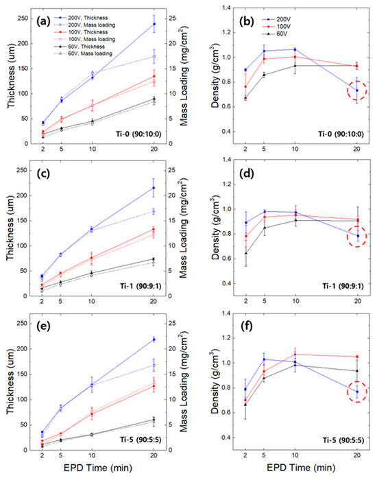
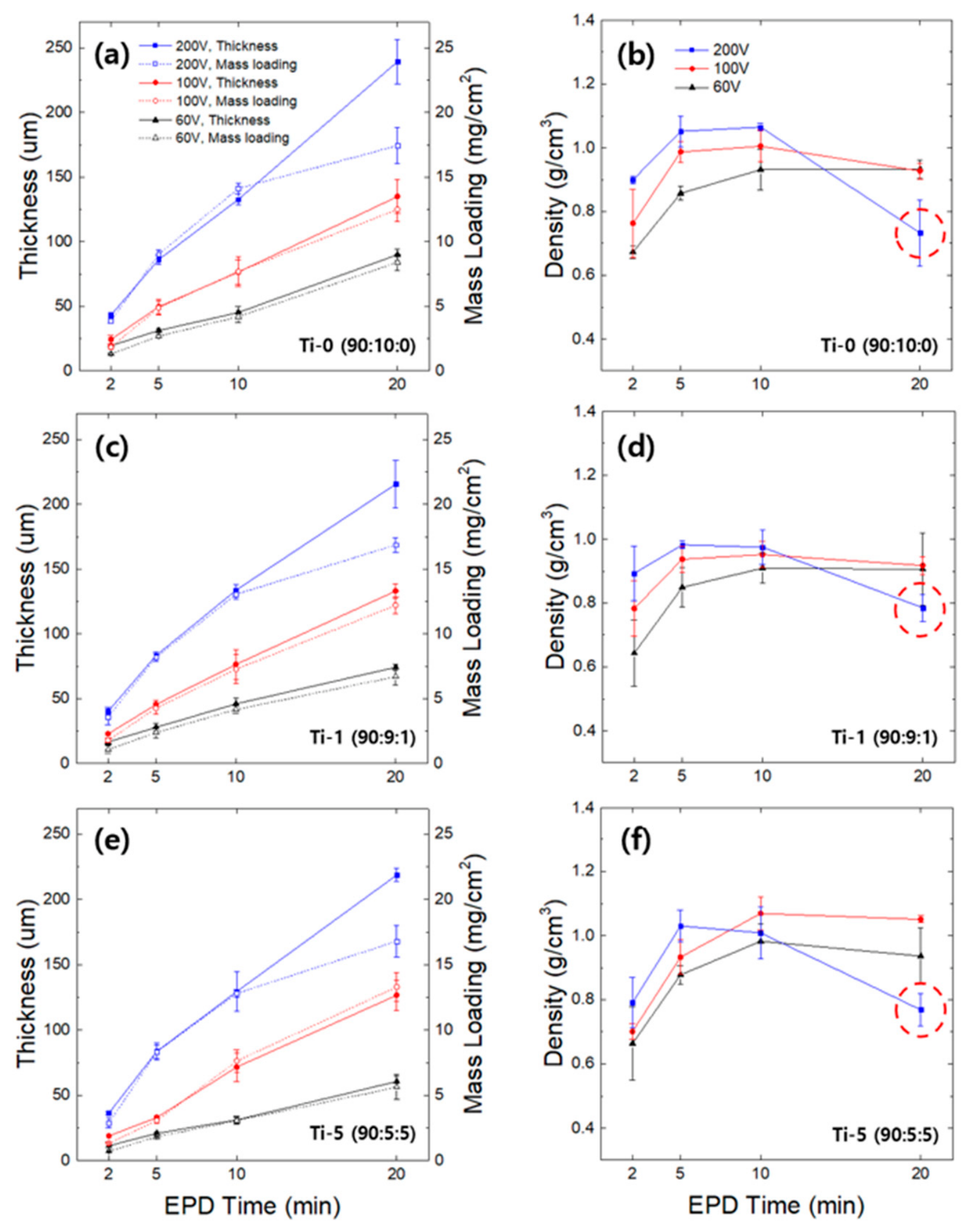
Figure 1 shows the changes in the physical properties of the electrodes according to the applied voltage (60, 100, and 200 V) and deposition time (2–20 min) under the three conductive additive conditions (Ti-0, Ti-1, and Ti-5). The electrode thickness and mass loading increased with the deposition time, and this trend was similar across all three compositions (Figure 1a,c,e). This demonstrates that the multi-component EPD process exhibited broadly similar deposition behavior across the conductive-additive compositions examined in this study. However, under conditions of both high voltage and prolonged deposition time, the increasing trend became less pronounced. Notably, at 200 V for 20 min, a distinct slowdown in the loading increase rate was observed.
Figure 1.
Physical characteristics of the multi-component EPD electrodes as a function of deposition time and applied voltage. (a,c,e) Electrode thickness (left y-axis) and areal mass loading (right y-axis), and (b,d,f) calculated packing density of the films fabricated under Ti-0 (a,b), Ti-1 (c,d), and Ti-5 (e,f) conditions. The red dotted circles highlight the significant drop in electrode density observed at the extreme condition of 200 V for 20 min. Error bars represent the standard deviation obtained from three independent experiments (n = 3). Some error bars are smaller than the data markers.
This trend is also reflected in the changes in electrode density (Figure 1b,d,f). During the initial deposition stage (2–5 min), the electrode density increased under all conditions, with a higher initial density forming at a higher applied voltage. However, as the deposition time increased, the extent of the density increase gradually diminished, approaching saturation after 10 min under most conditions. Notably, under the 200 V condition, the density slightly decreased after 10 min, and at 20 min, a drastic density drop was confirmed, as indicated by the red dotted circles in Figure 1b,d,f.
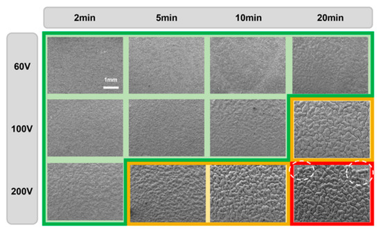
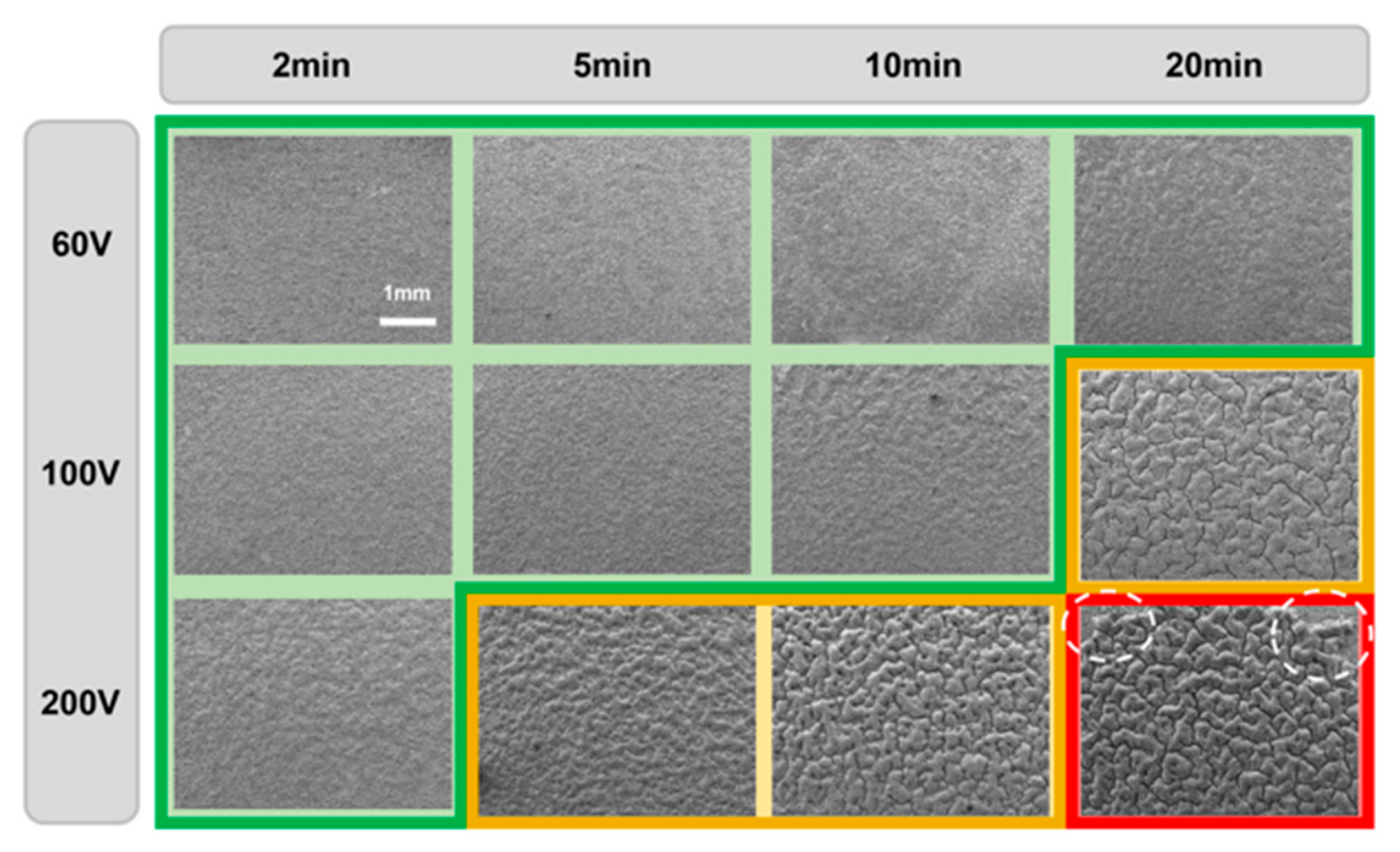
To identify the cause of this decrease in density, the surface microstructure of the electrode was analyzed (Figure 2 and Figure S2). Under conditions of low voltage and short deposition time, a relatively uniform structure with almost no surface defects was observed (green region). In contrast, under the 100 V, 20 min and 200 V, 5–10 min conditions, surface micro-cracks began to appear (yellow region), and under the 200 V, 20 min condition, severe cracks, and delamination were clearly observed across the entire electrode surface (red region).
Figure 2.
Surface morphological evolution of the multi-component EPD electrode prepared under the representative Ti-5 condition as a function of applied voltage and deposition time. Top-view scanning electron microscopy (SEM) images are categorized by colored borders indicating the structural integrity: uniform and stable surfaces without visible defects (green region), the onset of surface micro-cracks (yellow region), and severe structural degradation including macroscopic delamination (red region). In particular, the specific areas where delamination occurred are highlighted by white dotted circles. The results demonstrate that while uniform and dense coatings are formed at low voltages and short durations, mechanical failure becomes evident under high-voltage and prolonged deposition conditions.
Additionally, to more clearly identify the physical limits of the EPD process, conditions exceeding 200 V and 20 min were also examined. As shown in Figure S3, under the condition of an excessively prolonged deposition time of 200 V and 30 min, severe pores were formed on the electrode surface. On the other hand, under the condition of an excessively high applied voltage of 300 V and 5 min, the solvent boiled due to Joule heating, preventing the formation of the electrode.
To further examine whether the intermittent pause-and-stirring procedure affected the deposited structure, cross-sectional SEM images of electrodes prepared with and without intermediate stirring were compared (Figure S4). The electrode deposited without intermediate stirring showed more noticeable thickness variation along the vertical direction. In contrast, the electrode prepared with intermediate stirring exhibited a more uniform coating thickness. Importantly, no clear interlayer boundary or discontinuous interface corresponding to the temporary pause was observed. However, since the particle size, density, and surface charge characteristics are different in multi-component EPD, the suppression of surface defects alone is insufficient to determine the compositional uniformity inside the electrode. Accordingly, the cross-sectional composition and particle distribution of the electrodes fabricated under the standard condition were additionally analyzed.
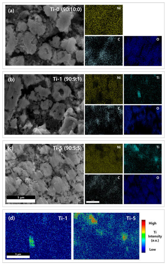
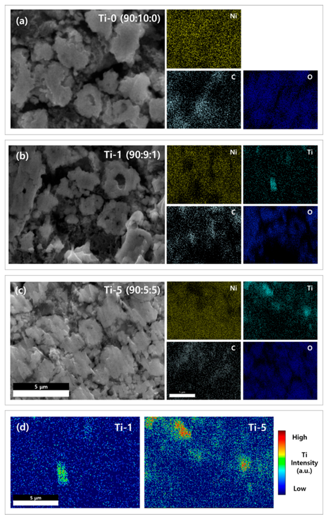
Figure 3 presents the cross-sectional morphology of the electrodes fabricated at 100 V for each composition, together with the corresponding EDS elemental maps. To improve the visibility of the local Ti distribution, the Ti elemental maps were replotted using adjusted contrast, and pseudo-color heatmap visualization was additionally applied. In all electrodes, the Ni signal associated with the cathode active material was broadly distributed over the mapped region. The C signal was also detected across the electrode in all cases. In the Ti-1 electrode, the Ti signal was relatively dispersed over the mapped region. In contrast, the Ti-5 electrode showed more pronounced local variation in the Ti signal. This visual difference was further quantified by grid-based Ti area-fraction analysis. The Ti-1 electrode showed an average Ti area fraction of 5.87%, with a standard deviation of 2.72 percentage points among the 25 subregions. In contrast, the Ti-5 electrode showed a higher average Ti area fraction of 9.91%, with a much larger standard deviation of 8.43 percentage points. Here, the standard deviation represents the spatial variation of the Ti-covered area fraction among the grid subregions, rather than experimental uncertainty. In addition, the calculated porosity values of the Ti-0, Ti-1, and Ti-5 electrodes were 46.05%, 45.52%, and 44.28%, respectively. These porosity values, together with the EDS mapping results, indicate that the electrochemical behavior of the electrodes should be interpreted not only in terms of electronic conductivity, but also in terms of local packing structure and ion-transport pathways.
Figure 3.
Cross-sectional compositional analysis and co-deposition behaviors of the multi-component EPD electrodes. Cross-sectional SEM images and corresponding EDS elemental maps for the films deposited under (a) Ti-0, (b) Ti-1, and (c) Ti-5 conditions, together with (d) pseudo-color heatmap visualization of the Ti distribution in Ti-1 and Ti-5 electrodes. Grid-based quantitative analysis of the Ti-covered area fraction was performed by dividing each Ti map into 5 × 5 subregions, and the results are discussed in the main text. The results show that the heterogeneous particles were co-deposited without apparent macroscopic segregation, although local Ti-related compositional heterogeneity became more noticeable with increasing Ti4O7 content.
Subsequently, to determine the compositional ratio, quantitative EDS analysis was performed on the cross-sections of the electrodes. From the quantitative analysis results in Figure S5, the final compositional ratios (NCM622:carbon: Ti4O7) of the deposited electrodes were confirmed as 90.5:9.5:0 for Ti-0, 90.6:8.2:1.2 for Ti-1, and 91.9:4.3:3.8 for Ti-5, respectively. Although some differences were observed in the absolute values, the overall compositional trends remained consistent with those of the initial suspension. These confirmed final compositions were utilized as the basis for interpreting the electrochemical properties hereafter.
Based on these microstructural observations, the subsequent electrochemical evaluations were performed under the 100 V condition, where structural stability and broadly distributed constituent particles were secured.
3.2. Effect of Conductive Additive Composition on Electrochemical Properties
Using electrodes fabricated at the optimized applied voltage of 100 V, the effects of conductive additive composition on electrochemical performance and high-voltage cycle-life stability were evaluated. Prior to electrochemical evaluation, tape-peel and bending tests qualitatively confirmed the good adhesion and flexibility of the EPD electrodes (Figure S6). Although micro-cracks began to appear at 100 V under the longest deposition time, 100 V was retained as the standard applied voltage because it provided the most practical balance between loading controllability and structural stability across the investigated conditions. In this study, the Ti-0 electrode was used as a carbon-only reference electrode because it was fabricated using the same NCM622 active material, EPD process, and loading-control protocol as the Ti-1 and Ti-5 electrodes, but without Ti4O7. Thus, a comparison among Ti-0, Ti-1, and Ti-5 allows for the composition-dependent role of Ti4O7 to be evaluated while minimizing the influence of other processing variables.
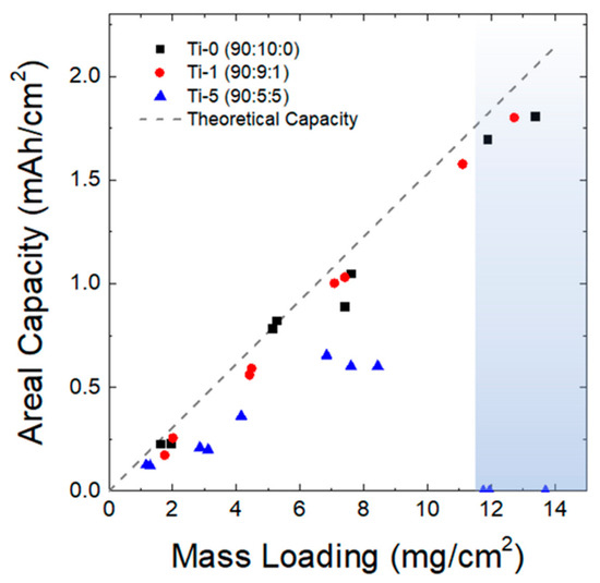
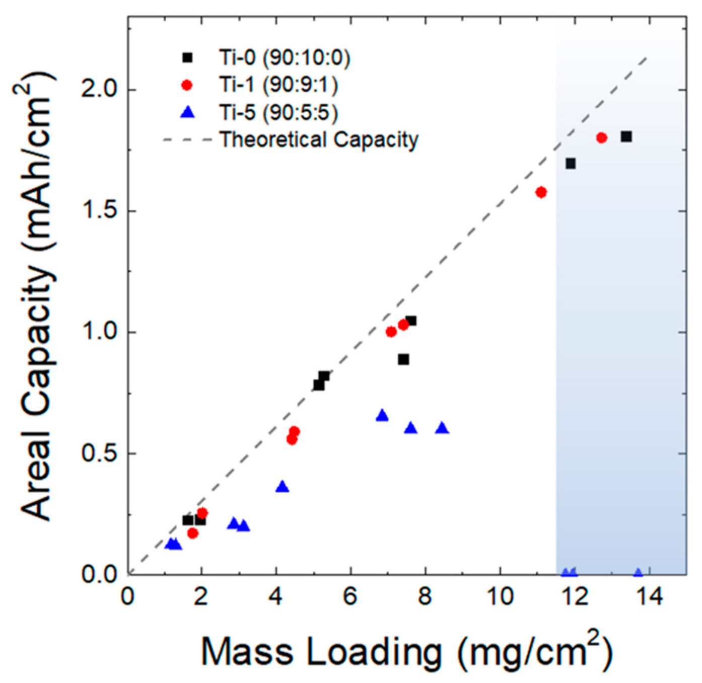
Figure 4 illustrates the changes in areal capacity relative to the mass loading of the EPD electrodes according to the conductive additive conditions (Ti-0, Ti-1, and Ti-5). Each loading condition was achieved by adjusting the deposition time (2, 5, 10, and 20 min), and the dotted line represents the theoretical areal capacity calculated based on the specific capacity of the active material. Under both the Ti-0 electrode (carbon-only) and the Ti-1 electrode (with a small amount of Ti4O7 added), the areal capacity increased linearly, close to the theoretical capacity, as the loading increased. This demonstrates that these compositions can maintain a relatively stable capacity delivery even as the electrode becomes thicker. Conversely, for the Ti-5 electrode (with a higher nominal Ti4O7 content), the rate of increase in areal capacity gradually diminished with increased loading. Particularly in the high-loading region of approximately 12 mg/cm2 or more, as indicated by the shaded region in the figure, the capacity delivery significantly deteriorated, leading to cell failure.
Figure 4.
Areal capacity as a function of mass loading for the multi-component EPD electrodes. The electrodes were deposited at a constant applied voltage of 100 V, with the mass loading controlled by varying the deposition duration. The discharge capacities were measured at a 0.1 C-rate within a voltage range of 2.5–4.3 V vs. Li+/Li. The graph compares three conductive additive conditions: Ti-0 (carbon-only reference electrode), Ti-1, and Ti-5. The gray dashed line represents the theoretical areal capacity based on the specific capacity of the active material. The shaded region indicates the critical high-loading region above approximately 12 mg cm−2, where the Ti-5 electrode exhibited severe capacity loss and cell failure.
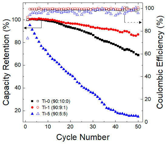
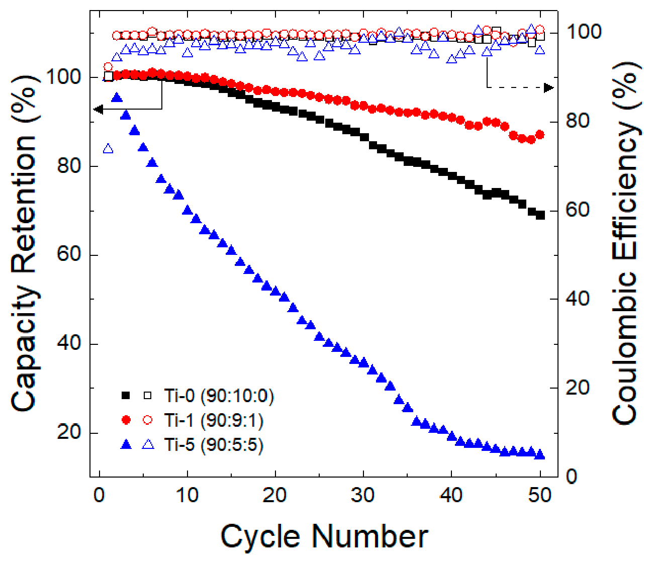
Subsequently, to evaluate the effect of Ti4O7 incorporation on battery durability in a high-voltage (4.5 V) environment, the electrode deposited for 10 min, which achieved the highest loading under the 100 V applied-voltage condition while retaining acceptable structural stability, was selected as the standard electrode for cycle-life evaluation. Figure 5 presents the cycle-life results and Coulombic efficiency changes over 50 cycles in a 4.5 V high-voltage environment for the electrodes fabricated under these conditions. The electrochemical trends described below were reproducibly observed across repeated cells, and representative data are shown. As the cycling progressed, the Ti-1 electrode with a small amount of Ti4O7 added generally exhibited the highest capacity-retention trend, while the Ti-0 electrode (carbon-only) showed a somewhat lower retention behavior in comparison. In contrast, the Ti-5 electrode exhibited a rapid capacity drop from the initial cycles. This trend was also consistent with the changes in Coulombic efficiency. While the Ti-1 and Ti-0 electrodes maintained a relatively stable Coulombic efficiency at the level of 98–99% during the 50 cycles, the Ti-5 electrode showed an unstable behavior, with the efficiency fluctuating irregularly between 94% and 98%.
Figure 5.
Electrochemical cycle performance and coulombic efficiency of the multi-component EPD electrodes. The cells were cycled at a constant current density of 0.5 C-rate under high-voltage conditions (2.5–4.5 V vs. Li/Li+). The capacity retention and coulombic efficiency are compared for three different conditions: Ti-0 (carbon-only reference electrode), Ti-1, and Ti-5. Representative cycling data are shown. The same composition-dependent trends were reproducibly observed across repeated cells.
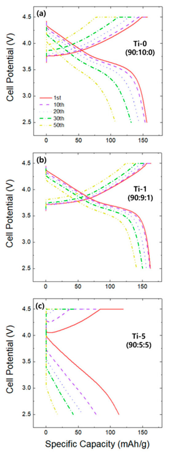
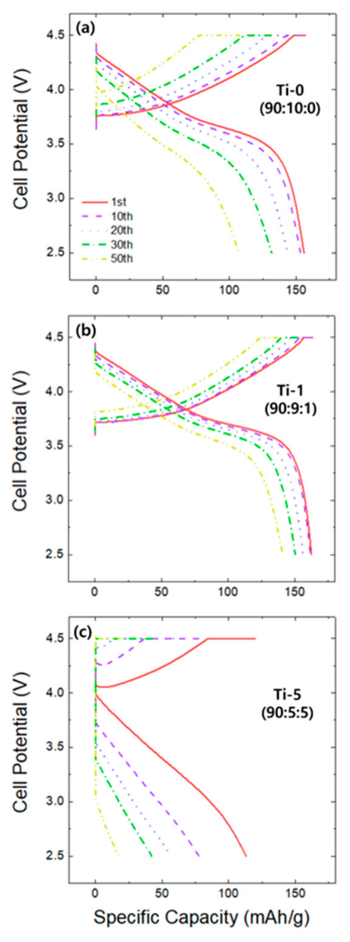
To further examine the cycle-life behavior of each composition, the changes in the galvanostatic charge–discharge voltage profiles as the cycling progressed were analyzed. Figure 6 presents the voltage curves of the Ti-0, Ti-1, and Ti-5 electrodes at the 1st, 10th, 20th, 30th, and 50th cycles. As cycling progressed, polarization phenomena were commonly observed in all electrodes. However, the rate of degradation and the pattern of voltage drop exhibited distinct differences depending on the conductive additive composition. The carbon-only electrode (Ti-0; Figure 6a) exhibited a clear pattern of increasing polarization over 50 cycles, characterized by a gradually increasing initial voltage drop and a noticeable increase in voltage hysteresis. Conversely, for the Ti-1 electrode with an appropriate amount of Ti4O7 (Figure 6b), the initial voltage drop and the extent of the polarization increase were significantly suppressed, keeping the charge–discharge curves highly compact throughout the 50 cycles. This suggests that the increase in polarization was relatively suppressed during cycling. In contrast, Ti-5 (Figure 6c) showed a significantly larger initial voltage drop than the other electrodes from the first cycle, and as the cycling progressed, the voltage profiles degraded rapidly, with both charge and discharge capacities decreasing substantially. Consequently, the voltage profile analysis suggests that polarization growth was relatively moderate with an appropriately designed hybrid conductive additive (Ti-1), supporting its improved relative cycling stability within the tested cycle range.
Figure 6.
Galvanostatic charge–discharge voltage profiles of the multi-component EPD electrodes at the 1st, 10th, 20th, 30th, and 50th cycles: (a) Ti-0 (carbon-only reference electrode), (b) Ti-1, and (c) Ti-5. The cells were tested within a voltage range of 2.5–4.5 V (vs. Li/Li+) at a 0.5 C-rate. The progressive widening of the gap between the charge and discharge curves represents the increased voltage hysteresis (polarization) during cycling, which was notably suppressed in the Ti-1 electrode compared to the Ti-0 and Ti-5 electrodes.
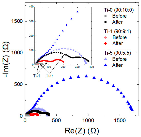
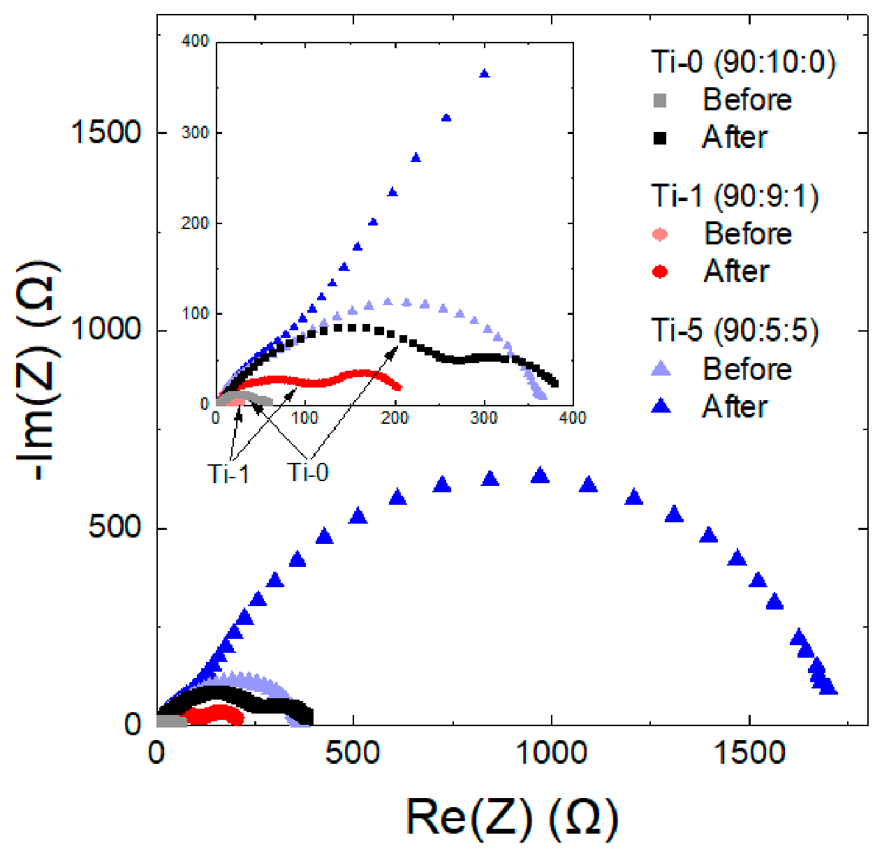
To electrochemically compare the composition-dependent degradation behavior identified in the preceding high-voltage cycle-life evaluation, EIS analysis was performed on the electrodes before and after the cycle-life test. Figure 7 shows the impedance measurement results presented as Nyquist plots according to the conductive additive conditions (Ti-0, Ti-1, and Ti-5). Because the impedance of the Ti-5 electrode was much larger than those of Ti-0 and Ti-1, the differences between Ti-0 and Ti-1 were difficult to distinguish in the full-scale Nyquist plot. Therefore, an enlarged linear-scale inset focusing on the high-frequency semicircle region of Ti-0 and Ti-1 is provided. In addition, the apparent resistance was estimated from the semicircle diameter to enable a more quantitative comparison of resistance evolution among the electrodes. This value should be regarded as an apparent interfacial resistance reflecting the combined contribution of multiple interfacial and transport-related processes, rather than a separately fitted charge-transfer resistance. Thus, the EIS analysis was used to compare the relative resistance evolution among the electrodes, rather than to strictly separate individual resistance components. After undergoing the cycle life evaluation under the 4.5 V high-voltage condition, the size of the semicircles increased in all electrodes. This result suggests an accumulation of interfacial changes and electrode degradation due to cycling. The Ti-0 electrode exhibited a relatively large increase in semicircle size after the cycle-life evaluation. On the other hand, the Ti-1 electrode maintained a relatively smaller semicircle compared to Ti-0 even after cycling, indicating that resistance growth under high-voltage cycling was relatively suppressed in Ti-1. Furthermore, the Ti-5 electrode exhibited a remarkable increase in semicircle size after cycling, suggesting the further deterioration of resistance-related processes within the electrode. The resistance changes observed before and after cycling in the EIS analysis were generally consistent with the capacity-retention results (Ti-1 > Ti-0 > Ti-5) observed in the cycle-life evaluation (Figure 5).
Figure 7.
Electrochemical impedance spectroscopy (EIS) analysis of the multi-component EPD electrodes. Nyquist plots were measured before and after 50 cycles for Ti-0 (carbon-only reference electrode), Ti-1, and Ti-5. The evolution of the semicircle size represents the change in interfacial resistance for each condition. The inset provides a magnified view of the high-frequency region to clearly distinguish the smaller semicircles of the Ti-0 and Ti-1 conditions, which are otherwise obscured in the main plot due to the severe resistance increase of the Ti-5 electrode after cycling.
4. Discussion
4.1. Structural Stability and Co-Deposition Behavior in Multi-Component EPD
Based on the density changes observed during the initial deposition stage (Figure 1), the higher initial density formed at a higher applied voltage suggests the possibility of a denser initial deposition under a stronger electric field. Furthermore, the drastic density drop confirmed at 200 V and 20 min indicates that structural changes leading to this density decrease likely occurred within the deposited layer formed under these high-voltage conditions. As observed in the surface microstructures (Figure 2), the formation of severe cracks is consistent with the density degradation observed in Figure 1 and indicates increased structural instability in the thick electrode layer formed under severe deposition conditions. Such cracking and delamination phenomena can be attributed to the shrinkage stress generated during the drying process. The electrode formed immediately after EPD is subjected to internal stress as the solvent evaporates during drying, and it is known that this stress increases as the electrode layer becomes thicker [38,39]. Therefore, when a thick electrode is formed, as in the 200 V, 20 min condition, the cracks likely intensified due to the influence of stress during drying. Consequently, the rapid density reduction observed under the 200 V, 20 min condition is likely associated with an increase in structural defects, such as cracking and delamination induced during the drying process.
Moreover, the observations under extreme conditions (Figure S3) demonstrate that excessive deposition times and high-voltage conditions are inappropriate in terms of process stability. Taken together, these findings indicate that the overall deposition behavior of the electrodes in the multi-component EPD process was largely independent of changes in the conductive additive composition, whereas the structural stability was significantly governed by the applied voltage and deposition time. Therefore, in this study, 100 V was selected as the standard applied voltage because it provided a practical balance between loading controllability and structural stability, offering a higher loading capability than 60 V while avoiding the severe structural deterioration observed at 200 V. The selection of 100 V can be further understood in terms of the balance between deposition kinetics and microstructural stability. At 60 V, the electric-field driving force was relatively weak, resulting in a slow increase in electrode loading, although the deposited layers remained mechanically stable. In contrast, at 200 V, the stronger electric field accelerated particle migration and deposition, enabling higher loading within a shorter time. However, this rapid accumulation likely promoted less uniform particle packing and greater stress buildup during drying, leading to surface microcracking, and under prolonged deposition, severe cracking and delamination. The 100 V condition therefore represents an intermediate deposition regime that provides sufficient loading controllability while avoiding the severe structural deterioration observed at 200 V.
To further ensure the microstructural uniformity required for high-performance electrodes, the effect of the intermittent pause-and-stirring procedure was also examined (Figure S4). The noticeable thickness variation along the vertical direction observed without intermediate stirring can be attributed to the sedimentation of relatively dense particles during deposition. Consequently, these results indicate that the pause-and-stirring procedure helped suppress sedimentation-induced non-uniformity without causing noticeable interfacial discontinuity in the deposited layer.
Based on the cross-sectional EDS analysis (Figure 3), the broad distribution of the Ni signal indicates that the active material was incorporated throughout the deposited layer. Similarly, for the Ti-1 electrode, the relatively dispersed Ti signal suggests that a small amount of Ti4O7 was incorporated without severe local accumulation. In contrast, the larger spatial variation in Ti-5 indicates that Ti-containing regions were more locally concentrated at a higher Ti4O7 content. These results suggest that the multi-component EPD process enabled co-deposition of the heterogeneous particles without apparent macroscopic phase separation, while local compositional heterogeneity became more pronounced as the Ti4O7 content increased. Furthermore, regarding the final compositional ratios confirmed by quantitative analysis (Figure S5), the observed deviation from the input composition likely reflects differences in electrophoretic mobility, sedimentation behavior, and dispersion stability among the particle types.
In summary, these results indicate that in the multi-component EPD process, electrode deposition behavior was relatively consistent across the compositional conditions examined, whereas structural stability was strongly influenced by the applied voltage and deposition time. In particular, under the 100 V condition, it was possible to form a structure where surface cracking was suppressed and the constituent particles were incorporated throughout the electrode without apparent segregation, although some local compositional heterogeneity remained depending on the Ti4O7 content.
4.2. Mechanistic Role of the Conductive Network in High-Voltage Stability
As comprehensively summarized in Table 1, the conductive additive composition significantly influenced both the local microstructural characteristics and the resulting high-voltage electrochemical performances of the composite electrodes fabricated at 100 V.
Table 1.
Summary of the quantitative and qualitative properties of the multi-component EPD electrodes under different conductive additive conditions (Ti-0, Ti-1, and Ti-5).
Specifically, regarding the performance under high-loading conditions (Figure 4), the slowdown in capacity delivery and the inability to operate under high-loading conditions can be understood in terms of a practical limitation in the effective percolation of the conductive network. Carbon black forms a chain-like structure consisting of agglomerated nanosized primary particles, which is advantageous for constructing continuous electronic pathways between active material particles. In contrast, although Ti4O7 possesses high intrinsic electronic conductivity, the Ti4O7 particles used in this study were relatively coarse and dense compared with carbon black. Consequently, when carbon black is excessively replaced by Ti4O7 on a weight basis, the effective volume fraction of the chain-like carbon network can be substantially reduced, making it more difficult to maintain long-range electronic percolation through the electrode thickness. This interpretation is supported by the quantitative cross-sectional EDS analysis (Figure S5). The final carbon contents in the Ti-0 and Ti-1 electrodes were maintained at approximately 9.5 and 8.2 wt%, respectively, and both electrodes exhibited stable capacity delivery over the investigated loading range. In contrast, the carbon content in Ti-5 decreased to 4.3 wt%, while the deposited Ti4O7 content was estimated to be 3.8 wt%. Although this amount of Ti4O7 contributes electronic conductivity, it appears insufficient to fully compensate for the reduced nanoscale carbon network. As the electrode loading increases, the electron-transport distance through the electrode thickness also increases. Therefore, above the critical high-loading region of approximately 12 mg cm−2, the reduced carbon network in Ti-5 likely becomes insufficient to maintain continuous electronic pathways throughout the thick electrode. This can increase internal resistance, intensify reaction non-uniformity, and eventually lead to capacity failure. These results indicate that the electrochemical performance of multi-component EPD electrodes is governed not only by the intrinsic conductivity of each additive, but also by the balance between particle morphology, effective volume fraction, and conductive-network percolation.
Furthermore, the differences in cycle-life characteristics (Figure 5) can be interpreted as reflecting the varying patterns of electrode performance degradation depending on the conductive additive composition in a high-voltage environment. The carbon-only electrode (Ti-0) showed gradual performance degradation as the cycles progressed, which is likely related to the limited high-voltage stability of the carbon-only conductive additive. Conversely, the Ti-1 electrode exhibited more moderate performance degradation compared to Ti-0. In contrast, as the proportion of the carbon conductive additive substantially decreased in the Ti-5 electrode, a rapid capacity drop and unstable Coulombic efficiency were observed from the early stages of cycling. This behavior is likely associated with the restricted conductive pathways within the electrode due to the change in conductive additive composition [6,7]. This limitation of conductive pathways is consistent with the rapid performance degradation observed during the high-voltage cycling process. In summary, the Ti-1 electrode, incorporating an appropriate amount of Ti4O7, exhibited more gradual capacity fade than Ti-0 and demonstrated the best cycle-life performance among the conditions examined in this study. It should be noted that the 50-cycle test at 4.5 V is not sufficient to conclusively demonstrate long-term stabilization of the NCM622 cathode. Therefore, the cycling results should be interpreted as a relative improvement within the tested high-voltage cycling condition. In addition, the Coulombic efficiencies of approximately 98–99% for Ti-0 and Ti-1 indicate that parasitic reactions are still present under the 4.5 V condition. Because the present study focused on conductive-additive design rather than electrolyte optimization or surface-coating strategies, high-voltage electrolyte oxidation and cathode/electrolyte interfacial side reactions may still contribute to the observed irreversible capacity loss. Extended cycling tests combined with additional interfacial-stabilization strategies will be required to evaluate long-term practical durability.
This limitation of conductive pathways is also evident in the voltage profiles and impedance spectra. The abnormal voltage behavior observed in Figure 6c indicates pronounced initial polarization, which is likely attributable to restricted conductive pathways inside the electrode. Importantly, even before cycling, the impedance semicircle of Ti-5 appeared significantly larger than those of the other electrodes (Figure 7). This is consistent with the pronounced initial voltage drop observed in the voltage profiles (Figure 6c) and the inability to operate under high-loading conditions (Figure 4), supporting the interpretation that the Ti-5 electrode had unfavorable initial transport characteristics.
Taken together, the cycling, voltage-profile, and EIS results are consistent with the interpretation that the improved behavior of Ti-1 arises from a balanced hybrid conductive network rather than from the simple replacement of carbon black by Ti4O7. In the Ti-0 electrode, electronic conduction is mainly provided by the percolating carbon black network, which is effective in forming continuous electron pathways because of its nanoscale primary particles, chain-like agglomerated structure, and large effective volume fraction. However, under high-voltage operation, carbon-based conductive additives can participate in interfacial side reactions and may gradually lose electrical connectivity. In the Ti-1 electrode, most of the carbon black network is preserved, while a small amount of Ti4O7 is incorporated into the conductive framework. Because Ti4O7 has high intrinsic electronic conductivity and oxide-based chemical stability, it may serve as a stable conductive bridge or contact-supporting component between the active material and the carbon network [40]. This complementary role is consistent with the reduced polarization growth and smaller apparent resistance increase observed for Ti-1. In contrast, excessive Ti4O7 incorporation in Ti-5 substantially reduces the carbon fraction, and the relatively coarse and dense Ti4O7 particles cannot fully replace the nanoscale percolating network formed by carbon black. Therefore, the favorable behavior of Ti-1 is plausibly attributed to a balanced hybrid conductive structure rather than the simple replacement of carbon black by Ti4O7. Among the conditions investigated in this study, the process condition of 100 V for 10 min combined with the Ti-1 composition showed the most favorable performance within the tested high-voltage cycling condition. Although Ti-1 showed the most favorable performance in this study, additional intermediate Ti4O7/carbon ratios will be required to determine the full composition–performance relationship and to identify the precise optimum composition. In addition, because no direct post-mortem surface analysis was performed in this study, the suppression of carbon degradation or cathode-electrolyte-interphase growth cannot be concluded directly. Therefore, the role of Ti4O7 should be regarded as a plausible interpretation based on the electrochemical results and the expected oxide-based stability of Ti4O7.
From a practical perspective, the present multi-component EPD approach provides a controllable platform for preparing composite cathodes over a broad loading range and for systematically investigating the co-deposition behavior of heterogeneous particles such as NCM622, carbon black, and Ti4O7. Because the deposited mass can be tuned by the applied voltage and deposition time, this process is useful for examining how electrode loading and conductive-additive composition affect electrochemical performance. In principle, EPD can also be extended to larger substrates or continuous processing systems because it is driven by an externally applied electric field. However, several technical challenges must be addressed for practical scale-up. First, suspension stability is critical because particles with different size, density, surface charge, and electrophoretic mobility can sediment or deposit at different rates. Second, excessive Ti4O7 addition can increase local compositional heterogeneity and reduce the effective carbon network, as observed for Ti-5. Third, for large-area deposition, uniform electric-field distribution, bath agitation, and suppression of Joule heating will be important engineering factors. Therefore, the present results demonstrate the usefulness of multi-component EPD as a controllable electrode-fabrication platform, while further optimization is required for practical large-scale implementation.
It should be noted that the present study does not aim to provide a direct process-level benchmark between EPD and optimized slurry-cast electrodes. Such a comparison would require the independent optimization of slurry formulation, binder content, drying conditions, calendaring pressure, and accessible loading range. Therefore, direct comparison with optimized slurry-cast reference electrodes under equivalent practical processing conditions remains an important topic for future work. At the same time, direct post-mortem surface and interfacial analyses after cycling will be necessary in future work to verify whether Ti4O7 actually suppresses carbon degradation or other interfacial degradation processes during high-voltage cycling.
5. Conclusions
In this study, NCM622/carbon black/Ti4O7 composite cathodes were fabricated by a multi-component EPD process, and the effects of the process conditions and conductive additive composition on electrode microstructure and electrochemical performance were systematically investigated. The main results are as follows:
- The deposition behavior was broadly similar across the compositional conditions examined, whereas structural stability strongly depended on the applied voltage and deposition time. Increasing voltage and deposition time increased mass loading, but severe conditions, particularly 200 V for 20 min, caused density reduction accompanied by cracking and delamination. In contrast, 100 V provided a practical balance between loading controllability and structural stability. Cross-sectional EDS analysis further showed that the heterogeneous particles were co-deposited throughout the electrode without apparent phase separation at the electrode scale, although local compositional heterogeneity became more noticeable at higher Ti4O7 content.
- The conductive additive composition had a clear influence on areal capacity and high-voltage cycle-life stability. Ti-0 and Ti-1 exhibited nearly linear increases in areal capacity with increasing loading, indicating stable capacity delivery over the loading range investigated. Among the compositions examined, Ti-1 showed the best electrochemical performance under 4.5 V cycling, with improved capacity retention and less pronounced resistance growth compared to Ti-0. This behavior is plausibly attributed to a balanced hybrid conductive structure, in which most of the percolating carbon black network is preserved while a small amount of Ti4O7 provides additional stable conductive contact points. In contrast, Ti-5 showed poor capacity delivery at high loading, unstable Coulombic efficiency, and severe performance degradation during cycling, which is likely to be associated with restricted conductive pathways resulting from reduced carbon content and increased local compositional heterogeneity. Further optimization using additional intermediate compositions is required to determine the full composition–performance relationship.
- EIS analysis before and after cycling revealed that resistance increased in all electrodes, but the extent of this increase depended strongly on composition. Ti-1 maintained the smallest post-cycle semicircle, whereas Ti-5 exhibited the largest resistance growth, consistent with the cycling and voltage-profile results. These findings indicate that multi-component EPD combined with an appropriate amount of Ti4O7 is a promising strategy for improving the structural and electrochemical stability of cathodes under high-voltage operation.
Supplementary Materials
The following supporting information can be downloaded at: https://www.mdpi.com/article/10.3390/en19133014/s1, Figure S1: Schematic illustration of the cathodic electrophoretic deposition (EPD) process and an optical photograph of the resulting as-deposited electrode; Figure S2: Top-view SEM images demonstrating the morphological evolution of the (a) Ti-0 and (b) Ti-1 electrodes under various EPD conditions (applied voltage: 60–200 V, deposition time: 2–20 min); Figure S3: Identification of EPD process limitations and morphological defects formed under extreme conditions; Figure S4: Cross-sectional SEM comparison of EPD electrodes prepared (a) without and (b) with the intermediate pause-and-stirring procedure during a total deposition time of 10 min; Figure S5: Energy-dispersive X-ray spectroscopy (EDS) spectra and the corresponding quantitative elemental analysis tables for the EPD electrodes prepared with different initial suspension formulations: (a) Ti-0, (b) Ti-1, and (c) Ti-5; Figure S6: Macroscopic mechanical stability and flexibility of the prepared EPD electrode.
Author Contributions
Conceptualization, C.-H.P.; Methodology, C.-H.P. and S.-Y.K.; Validation, C.-H.P., S.-Y.K. and H.-C.S.; Investigation, C.-H.P.; Data curation, C.-H.P. and S.-Y.K.; Writing—original draft, C.-H.P.; Writing—review & editing, S.-Y.K. and H.-C.S.; Supervision, H.-C.S.; Project administration, H.-C.S.; Funding acquisition, H.-C.S. All authors have read and agreed to the published version of the manuscript.
Funding
This work was supported by the National Research Foundation of the Ministry of Science and ICT (RS-2025-00512708), by the Technology Innovation Program (20007045) funded by the Ministry of Trade, Industry & Energy (MOTIE), and by the Korea Institute of Energy Technology Evaluation and Planning (KETEP) and the Ministry of Climate, Energy & Environment (MCEE) of the Republic of Korea (No. 20224000000400).
Data Availability Statement
The original contributions presented in this study are included in the article/Supplementary Materials. Further inquiries can be directed to the corresponding author.
Conflicts of Interest
The authors declare no conflicts of interest.
References
- Choi, D.; Shamim, N.; Crawford, A.; Huang, Q.; Vartanian, C.K.; Viswanathan, V.V.; Paiss, M.D.; Alam, M.J.E.; Reed, D.M.; Sprenkle, V.L. Li-ion battery technology for grid application. J. Power Sources 2021, 511, 230419. [Google Scholar] [CrossRef] [Scilit]
- Ghosh, S.; Bhattacharjee, U.; Bhowmik, S.; Martha, S.K. A review on high-capacity and high-voltage cathodes for next-generation lithium-ion batteries. J. Energy Power Technol. 2022, 1, 002. [Google Scholar]
- Fu, K.; Li, X.; Sun, K.; Zhai, S.; Yang, H.; Gong, L.; Tan, P. Thick electrode design for lithium-ion batteries from an ion-electron coupled transport perspective: From independent regulation to cooperative design. Energy Z 2026, 2, 200002. [Google Scholar]
- Wang, T.; Yao, H.; Luo, Z.; Zhu, J.; Liang, J.; Shi, Z.; Wu, Y. Interface-regulated bifunctional separator for highly robust lithium sulfur batteries. Mater. Today 2026, 97, 103363. [Google Scholar] [CrossRef] [Scilit]
- Su, F.Y.; He, Y.B.; Li, B.; Chen, X.C.; You, C.H.; Wei, W.; Lv, W.; Yang, Q.H.; Kang, F. Could graphene construct an effective conducting network in a high-power lithium ion battery? Nano Energy 2012, 1, 429–439. [Google Scholar] [CrossRef] [Scilit]
- Schmidt, O.; Röder, F. Conductive networks and their impact on uncertainty, degradation, and failure of lithium-ion battery electrodes. ACS Appl. Energy Mater. 2021, 4, 4845–4860. [Google Scholar] [CrossRef] [Scilit]
- Baumgärtner, J.F.; Kravchyk, K.V.; Kovalenko, M.V. Navigating the Carbon Maze: A Roadmap to Effective Carbon Conductive Networks for Lithium-Ion Batteries. Adv. Energy Mater. 2025, 15, 2400499. [Google Scholar]
- Chakrabarti, B.K.; Gençten, M.; Bree, G.; Dao, A.H.; Mandler, D.; Low, C.T.J. Modern practices in electrophoretic deposition to manufacture energy storage electrodes. Int. J. Energy Res. 2022, 46, 13205–13250. [Google Scholar] [CrossRef] [Scilit]
- Kumano, N.; Yamaguchi, Y.; Akimoto, Y.; Ohshima, A.; Nakamura, H.; Yamamura, M. Migration of binder and conductive agent during drying process of Li-ion battery cathodes. J. Power Sources 2024, 591, 233883. [Google Scholar]
- Zheng, J.; Xiao, J.; Xu, W.; Chen, X.; Gu, M.; Li, X.; Zhang, J.G. Surface and structural stabilities of carbon additives in high voltage lithium ion batteries. J. Power Sources 2013, 227, 211–217. [Google Scholar] [CrossRef] [Scilit]
- Younesi, R.; Christiansen, A.S.; Scipioni, R.; Simonsen, S.B.; Edström, K.; Hjelm, J.; Norby, P. Analysis of the interphase on carbon black formed in high voltage batteries. J. Electrochem. Soc. 2015, 162, A1289. [Google Scholar] [CrossRef] [Scilit]
- Liu, S.; Zeng, X.; Liu, D.; Wang, S.; Zhang, L.; Zhao, R.; Kang, F.; Li, B. Understanding the conductive carbon additive on electrode/electrolyte interface formation in lithium-ion batteries via in situ scanning electrochemical microscopy. Front. Chem. 2020, 8, 114. [Google Scholar] [CrossRef] [Scilit] [PubMed]
- Qi, X.; Blizanac, B.; DuPasquier, A.; Lal, A.; Niehoff, P.; Placke, T.; Oljaca, M.; Li, J.; Winter, M. Influence of thermal treated carbon black conductive additive on the performance of high voltage spinel Cr-doped LiNi0.5Mn1.5O4 composite cathode electrode. J. Electrochem. Soc. 2014, 162, A339. [Google Scholar]
- Kajiyama, A.; Masaki, R.; Wakiyama, T.; Matsumoto, K.; Yoda, A.; Inada, T.; Yokota, H.; Kanno, R. Principal factors of carbon conductive agents that contribute to the gas formation in high-voltage cathode systems. J. Electrochem. Soc. 2015, 162, A1516. [Google Scholar] [CrossRef] [Scilit]
- Qi, X.; Blizanac, B.; DuPasquier, A.; Meister, P.; Placke, T.; Oljaca, M.; Li, J.; Winter, M. Investigation of PF6− and TFSI- anion intercalation into graphitized carbon blacks and its influence on high voltage lithium ion batteries. Phys. Chem. Chem. Phys. 2014, 16, 25306–25313. [Google Scholar] [CrossRef] [Scilit] [PubMed]
- Ko, S.; Yamada, Y.; Yamada, A. An overlooked issue for high-voltage Li-ion batteries: Suppressing the intercalation of anions into conductive carbon. Joule 2021, 5, 998–1009. [Google Scholar] [CrossRef] [Scilit]
- Golovina, I.S.; Falmbigl, M.; Plokhikh, A.V.; Parker, T.C.; Johnson, C.; Spanier, J.E. Effect of annealing conditions on the electrical properties of ALD-grown polycrystalline BiFeO3 films. J. Mater. Chem. C 2018, 6, 5462–5472. [Google Scholar] [CrossRef] [Scilit]
- Ramazanov, S.; Sobola, D.; Ţălu, Ş.; Orudzev, F.; Arman, A.; Kaspar, P.; Ramazanov, G. Multiferroic behavior of the functionalized surface of a flexible substrate by deposition of Bi2O3 and Fe2O3. Microsc. Res. Tech. 2022, 85, 1300–1310. [Google Scholar] [PubMed]
- Kanamura, K.; Goto, A.; Rho, Y.H.; Umegaki, T. Electrophoretic fabrication of LiCoO2 positive electrodes for rechargeable lithium batteries. J. Power Sources 2001, 97, 294–297. [Google Scholar] [CrossRef] [Scilit]
- Wu, M.S.; Huang, C.Y.; Lin, K.H. Electrophoretic deposition of nickel oxide electrode for high-rate electrochemical capacitors. J. Power Sources 2009, 186, 557–564. [Google Scholar] [CrossRef] [Scilit]
- Mazor, H.; Golodnitsky, D.; Burstein, L.; Gladkich, A.; Peled, E. Electrophoretic deposition of lithium iron phosphate cathode for thin-film 3D-microbatteries. J. Power Sources 2012, 198, 264–272. [Google Scholar] [CrossRef] [Scilit]
- Lalau, C.C.; Low, C.T.J. Electrophoretic deposition for lithium-ion battery electrode manufacture. Batter. Supercaps 2019, 2, 551–559. [Google Scholar] [CrossRef] [Scilit] [PubMed]
- Gonzalez, Z.; Yus, J.; Moratalla, R.; Ferrari, B. Electrophoretic deposition of binder-free TiN nanoparticles to design 3D microstructures. The role of sintering in the microstructural robustness of supercapacitor electrodes. Electrochim. Acta 2021, 369, 137654. [Google Scholar] [CrossRef] [Scilit]
- Chakrabarti, B.K.; Low, C.T.J. Practical aspects of electrophoretic deposition to produce commercially viable supercapacitor energy storage electrodes. RSC Adv. 2021, 11, 20641–20650. [Google Scholar] [CrossRef] [Scilit] [PubMed]
- Majumder, T.; Das, D.; Majumder, S.B. Investigations on the electrochemical characteristics of electrophoretically deposited NiTiO3 negative electrode for lithium-ion rechargeable cells. J. Phys. Chem. Solids 2021, 158, 110239. [Google Scholar] [CrossRef] [Scilit]
- Bree, G.; Low, C.T.J. Full Cell Lithium-Ion Battery Manufacture by Electrophoretic Deposition. Batter. Supercaps 2023, 6, e202200441. [Google Scholar]
- Besra, L.; Liu, M. A review on fundamentals and applications of electrophoretic deposition (EPD). Prog. Mater. Sci. 2007, 52, 1–61. [Google Scholar] [CrossRef] [Scilit]
- Van der Biest, O.O.; Vandeperre, L.J. Electrophoretic deposition of materials. Annu. Rev. Mater. Sci. 1999, 29, 327–352. [Google Scholar] [CrossRef] [Scilit]
- Li, X.; Zhu, A.L.; Qu, W.; Wang, H.; Hui, R.; Zhang, L.; Zhang, J. Magneli phase Ti4O7 electrode for oxygen reduction reaction and its implication for zinc-air rechargeable batteries. Electrochim. Acta 2010, 55, 5891–5898. [Google Scholar]
- Wang, Y.; Zhao, D.; Zhang, K.; Li, Y.; Xu, B.; Liang, F.; Dai, Y.; Yao, Y. Enhancing the rate performance of high-capacity LiNi0.8Co0.15Al0.05O2 cathode materials by using Ti4O7 as a conductive additive. J. Energy Storage 2020, 28, 101182. [Google Scholar]
- Ekanayake, S.A.; Mai, H.; Chen, D.; Caruso, R.A. Recent advances in synthesis and application of Magnéli phase titanium oxides for energy storage and environmental remediation. Chem. Sci. 2025, 16, 2980–3018. [Google Scholar] [CrossRef] [Scilit] [PubMed]
- Benehkohal, N.P.; Sussman, M.J.; Chiu, H.C.; Uceda, M.; Gauvin, R.; Demopoulos, G.P. Enabling green fabrication of Li-ion battery electrodes by electrophoretic deposition: Growth of thick binder-free mesoporous TiO2-carbon anode films. J. Electrochem. Soc. 2015, 162, D3013. [Google Scholar] [CrossRef] [Scilit]
- Michaud, X.; Shi, K.; Zhitomirsky, I. Electrophoretic deposition of LiFePO4 for Li-ion batteries. Mater. Lett. 2019, 241, 10–13. [Google Scholar] [CrossRef] [Scilit]
- Miyazaki, H.; Mimaru, Y.; Makinose, Y.; Tsuji, T.; Yamada, H.; Mutai, T. Improvement of the cycle property of binder-free LiCoO2 positive electrode film deposited via the pulsed electrophoretic deposition. Mater. Trans. 2019, 60, 2576–2579. [Google Scholar]
- Vandeperre, L.; Van der Biest, O.; Clegg, W.J. Silicon carbide laminates with carbon interlayers by electrophoretic deposition. Key Eng. Mater. 1996, 127, 567–574. [Google Scholar] [CrossRef] [Scilit]
- Ye, L.; Wen, K.; Zhang, Z.; Yang, F.; Liang, Y.; Lv, W.; Lin, Y.; Gu, J.; Dickerson, J.H.; He, W. Highly efficient materials assembly via electrophoretic deposition for electrochemical energy conversion and storage devices. Adv. Energy Mater. 2016, 6, 1502018. [Google Scholar] [CrossRef] [Scilit]
- Tolganbek, N.; Zhalgas, N.; Kadyrov, Y.; Umirov, N.; Bakenov, Z.; Mentbayeva, A. Facile deposition of the LiFePO4 cathode by the electrophoresis method. ACS Omega 2023, 8, 8045–8051. [Google Scholar] [CrossRef] [Scilit] [PubMed]
- Peng, Z.; Liu, M. Preparation of Dense Platinum-Yttria Stabilized Zirconia and Yttria Stabilized Zirconia Films on Porous La0.9Sr0.1MnO3 (LSM) Substrates. J. Am. Ceram. Soc. 2001, 84, 283–288. [Google Scholar]
- Sarkar, P.; De, D.; Rho, H. Synthesis and microstructural manipulation of ceramics by electrophoretic deposition. J. Mater. Sci. 2004, 39, 819–823. [Google Scholar] [CrossRef] [Scilit]
- Wang, H.; Guo, B.; Xiong, Z.; Jian, X.; Zhu, X. Impact of Ti4O7 conductive additive in NCM111 cathode for high-performance lithium-ion batteries. J. Mater. Sci. 2025, 60, 10380–10392. [Google Scholar] [CrossRef] [Scilit]

Disclaimer/Publisher’s Note: The statements, opinions and data contained in all publications are solely those of the individual author(s) and contributor(s) and not of MDPI and/or the editor(s). MDPI and/or the editor(s) disclaim responsibility for any injury to people or property resulting from any ideas, methods, instructions or products referred to in the content. |
© 2026 by the authors. Licensee MDPI, Basel, Switzerland. This article is an open access article distributed under the terms and conditions of the Creative Commons Attribution (CC BY) license.