


Abstract
Wound-rotor synchronous machines (WRSMs) offer a promising, magnet-free alternative for safety-critical transportation sectors like electric vehicles (EVs) and marine propulsion. While multiphase structures enhance fault tolerance in these applications, conventional WRSMs still suffer from reliance on maintenance-prone slip rings and brushes. Brushless multiphase self-excitation presents a compelling solution, but it introduces a critical design challenge: ensuring decoupled control between the torque-producing (αβ) and magnetizing () subspaces to prevent severe performance degradation. To address this cross-coupling issue, this paper proposes a 20-slot/18-pole five-phase architecture. By exploiting distinct spatial harmonics, the stator generates two independently controlled magnetic fields with a dedicated rotor harmonic winding. An integrated diode rectifier then seamlessly converts the induced AC voltages into the required DC field excitation. Extensive finite-element analysis (FEA) using ANSYS Maxwell is conducted to validate the design and rigorously evaluate subspace cross-coupling. Simulation results confirm that the proposed machine meets design specifications, demonstrating stable self-excited operation, acceptable efficiency, and representative fault-tolerant operation under a single open-phase condition, thereby confirming the electromagnetic feasibility of the proposed topology as a promising magnet-free candidate for future alternatives to PMSM-based traction solutions.
1. Introduction
The push toward green mobility has made the electrification of the transportation sector a major engineering priority [1]. Electric vehicles (EVs) and marine propulsion systems, in particular, require electric drives capable of delivering high torque density, thermal robustness, and sustained efficiency across a wide range of operating conditions [2,3]. Permanent Magnet Synchronous Machines (PMSMs) are the current industry standard due to their high specific power [4,5]. However, the volatile cost of rare-earth materials remains a major concern. Furthermore, there is a significant risk of thermal demagnetization under heavy loads [6,7].
Consequently, researchers are revisiting magnet-free alternatives such as wound-rotor synchronous machines (WRSMs), also known as electrically excited synchronous machines (EESMs) [8]. WRSMs offer an extra degree of control freedom through an adjustable excitation flux. This feature allows for efficiency optimization across varying loads and deep flux-weakening regions [9]. Safety-critical transportation systems also demand strict fault tolerance. To meet these demands, multiphase machine structures are often employed [10,11]. Extensive research demonstrates that among the available configurations, five-phase and six-phase architectures generally offer the most optimal trade-offs [12,13]. These specific phase numbers strike a practical balance, improving system reliability and lowering torque pulsation while keeping inverter costs and control complexity manageable [14].
Despite their electromagnetic advantages, conventional WRSMs rely on mechanical brushes and slip rings. These components deliver the necessary excitation power to the rotor [15,16]. These mechanical contacts wear out quickly and introduce sparking risks. As a result, they frequently become the primary point of failure in the machine [17]. Wireless power transfer (WPT) using rotary transformers and a high-frequency dual-active-bridge (DAB) converter can remove these physical contacts [18,19]. However, this method introduces added penalties to the overall system volume [20].
An alternative and increasingly attractive concept to achieve maintenance-free operation is self-excitation [21]. Instead of relying on separate rotary transformers, self-excitation utilizes the machine’s existing magnetic circuit to induce power across the air gap [22,23]. Among the various proposed techniques detailed in recent surveys [24], the multiphase-based harmonic self-excitation architecture is particularly promising. This approach achieves wireless power transfer by exploiting targeted spatial harmonics. These harmonics are inherent in the stator’s magneto-motive force (MMF). This greatly simplifies the rotor-side electronics because only a passive diode bridge rectifier is required to convert the induced alternating current into a stable DC field excitation [25]. This creates a highly reliable self-excited brushless WRSM (SBWRSM). This improvement optimizes both the volumetric footprint and the long-term reliability of the machine.
It is also useful to distinguish the SBWRSM topology from induction machines (IMs), which are another major magnet-free drive solution. In both IMs and SBWRSMs, field-oriented control (FOC) can regulate torque-producing and flux-producing current components independently. The IM has the advantage of a simple, robust, and low-cost squirrel-cage rotor, making it attractive where mechanical simplicity is the dominant requirement. However, synchronous machines are generally preferred in many transportation drives because they can achieve higher torque density and higher efficiency than IMs.
In this context, the comparison reported in [25] showed that SBWRSMs can outperform IMs over the investigated speed range and can become nearly competitive with PMSMs in the constant-power region. Therefore, the investigated 20-slot/18-pole SBWRSM is positioned as a magnet-free synchronous-machine candidate that combines controllable rotor excitation, brushless operation, and multiphase fault-tolerant capability. The main trade-off is the more complex rotor structure, since it must include a harmonic winding, a field winding, and a rotating diode rectifier, in addition to the extra losses and voltage demand associated with the high-frequency excitation path.
However, despite this immense potential, the design of multiphase self-excited machines remains an emerging and highly complex research area. The current literature lacks detailed design methodologies, particularly for high pole-count fractional-slot configurations. More critically, previous studies have not sufficiently addressed the cross-coupling phenomena between the fundamental torque-producing subspace () and the harmonic magnetizing subspace (), a relationship governed by Vector Space Decomposition (VSD) theory [26]. In multiphase self-excited machines driven by a single inverter, keeping the torque-producing current and the magnetizing current fully decoupled is essential. Without careful winding design, specific spatial harmonics are shared between the two subspaces. This cross-coupling heavily may degrade dynamic performance, cause asymmetrical magnetic saturation, and lead to severe torque ripples. While Fractional-Slot Concentrated Winding (FSCW) designs offer a pathway to shape the MMF spectrum [27,28], applying them to brushless excitation requires analytical decoupling.
A further consequence of this decoupled mechanism is its ability to fully establish the rotor field at standstill. This means the field can be built even when the fundamental torque-producing stator frequency is zero. The excitation path relies solely on the independently injected high-frequency -subspace current. Therefore, a full-field build-up at a zero fundamental frequency is entirely possible. This requires only that the inverter retains a sufficient high-frequency voltage headroom. This feature guarantees a maximum torque capability during startup. Importantly, it achieves this without requiring any physical rotor rotation.
The current literature lacks investigations into high-pole-count FSCW combinations for self-excited operation. Specifically, the feasibility of a five-phase 20-slot/18-pole (20s/18p) configuration remains unexplored. Therefore, this paper assesses whether this specific combination provides suitable harmonic separation, acceptable cross-coupling behavior, and viable brushless excitation. Among the feasible five-phase FSCW candidates identified in [29], the 20s/18p topology was selected for its high power density and fault-tolerant potential. As summarized in Table 1, it provides a favorable compromise between high winding-factor quality and rotor implementation simplicity. While the 15/16 combination offers comparable winding factors, its odd-slot stator increases the risk of unbalanced magnetic pull (UMP) and elevated acoustic noise. The even-slotted 20s/18p design successfully avoids these mechanical vulnerabilities. In this configuration, the 9th spatial harmonic drives torque production. Concurrently, the 7th spatial harmonic induces rotor excitation [24]. This mechanism requires only a relatively simple 14-pole, three-phase rotor harmonic winding and an onboard rectifier.
Table 1.
Comparison of the most promising five-phase FSCW slot/pole candidates for self-excited operation.
To evaluate this topology, the proposed 20s/18p SBWRSM is analyzed using analytical design and ANSYS Maxwell (Version 2021) finite-element analysis (FEA). The evaluation focuses on self-excitation capability, subspace cross-coupling, and efficiency. This study is intended strictly as a prototype-scale electromagnetic feasibility assessment, rather than a complete transportation-machine validation.
The remainder of this paper is organized as follows: Section 2 details the proposed machine topology, VSD integration, and the working principle of multiphase harmonic excitation. Section 3 presents the analytical sizing equations and the proposed systematic multi-stage machine design procedure. Section 4 provides FEA and comprehensive performance evaluation. Finally, Section 5 outlines the conclusions.
2. System Overview
This section details the system architecture and the multiphase harmonic excitation physics that govern the proposed 20s/18p five-phase SBWRSM.
2.1. System Architecture
The core operational principle of the proposed SBWRSM relies on the generation of two independent rotating magnetic fields within the same air gap.
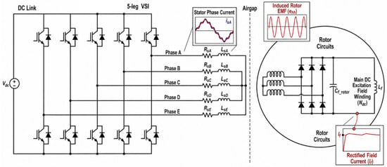
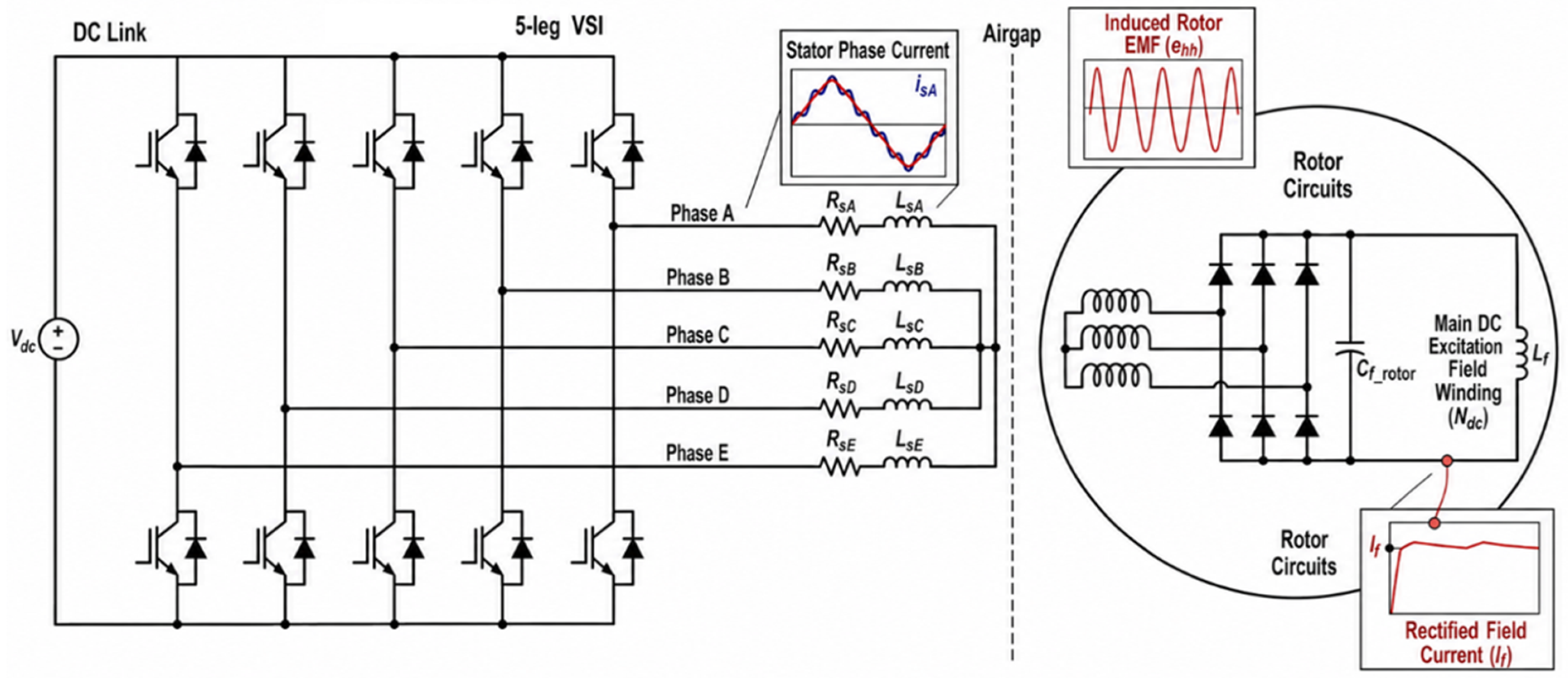
To achieve this with minimal mutual interference, the system exploits the additional degrees of freedom inherent in a five-phase stator architecture. As illustrated in the detailed block diagram of Figure 1, the complete drive system integrates a conventional five-phase two-level Voltage Source Inverter (VSI), a fractional-slot five-phase stator winding armature, and a specifically configured brushless self-excited rotor assembly.
Figure 1.
Proposed five-phase topology for a SBWRSM.
On the stator side, the 20-slot winding is driven by the VSI. To achieve independent control of torque and excitation within a single machine structure, the system utilizes the VSD theory. Through standard VSD-based FOC, the injected stator phase currents are mapped into mathematically orthogonal subspaces. Current components mapped to the fundamental torque-producing subspace () generate the primary rotating magnetic field responsible for electromagnetic torque. Simultaneously, current components mapped to the harmonic magnetizing subspace () are utilized to inject a targeted spatial sub-harmonic MMF into the air-gap solely for rotor excitation. Since VSD-based control of five-phase machines is a well-established topic, only its role in generating the required and current components is considered here; full controller details can be found in [30].
To harness this excitation power, the 18-pole rotor houses two specialized, electrically distinct winding sets: a three-phase 14-pole harmonic winding (HW) and the main 18-pole direct-current (DC) field winding (FW), as depicted in Figure 1. During operation, the spatial sub-harmonic MMF generated by the stator subspace currents couples magnetically with the rotor’s harmonic winding (HW), wirelessly inducing alternating current (AC) voltages through integrated transformer action. The conversion from AC induction to stable DC excitation is managed seamlessly on the rotating shaft via a three-phase full-bridge diode rectifier. This passive rectifier assembly converts the induced AC voltages into a stable DC field current (), directly powering the main field winding (FW) to establish the necessary machine flux. More specifically, the rotor harmonic winding is designed to couple primarily with the dominant spatial harmonic generated by the stator -subspace current sequence, whereas the dominant spatial harmonic associated with the stator subspace is responsible for torque production through interaction with the main 18-pole field winding. Crucially, because the magnitude of the harmonic magnetizing current in the stator subspace is regulated independently from the fundamental torque current, this topology provides the basis for flux-weakening capability and torque regulation without requiring wear-prone mechanical brushes, slip rings, or supplementary external DC converters.
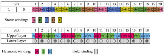
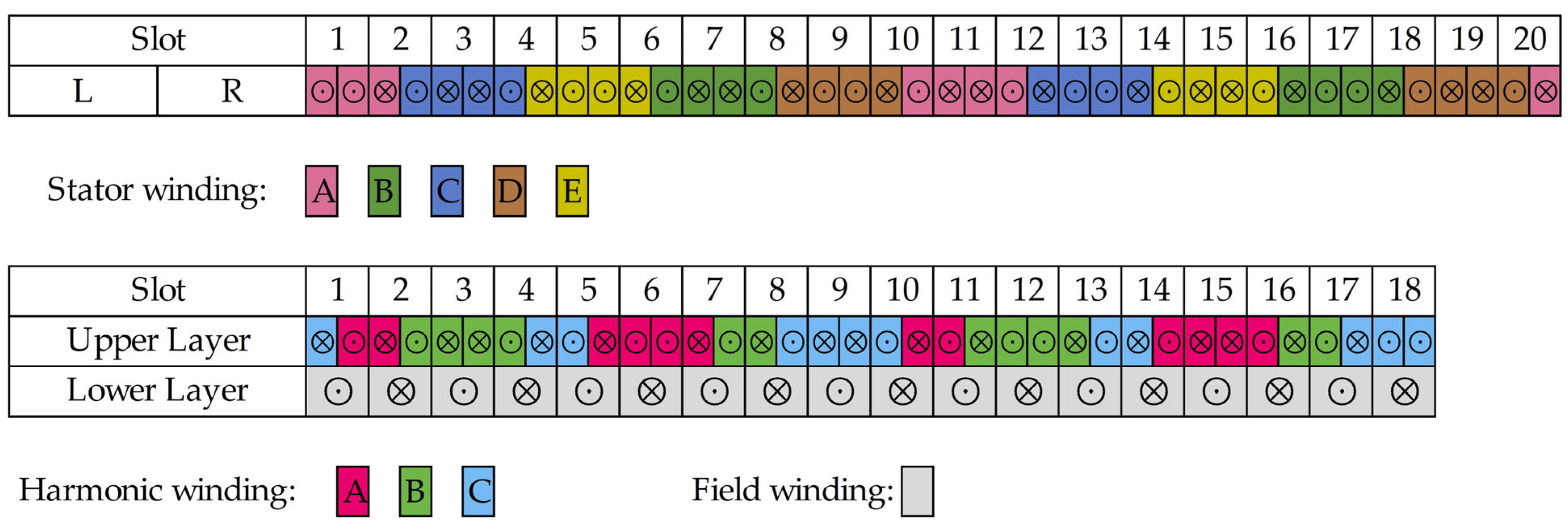
To achieve the required decoupled operation, the winding layout must be carefully designed to generate the precise spatial MMF distributions for both subspaces. For the proposed 20s/18p combination and its corresponding phase sequence, the specific winding arrangement is configured according to the fractional-slot harmonic decoupling concepts introduced in [27]. The complete spatial layout of the multiphase stator armature and the associated rotor windings are illustrated in Figure 2. In this representation, the symbols ⊙ and ⊗ indicate outgoing and return conductors, respectively. The figure shows the spatial distribution of the conductors around the stator and rotor periphery and is intended to clarify the physical placement of the three winding systems, namely the five-phase stator armature winding, the three-phase rotor harmonic winding, and the main DC rotor field winding.
Figure 2.
Circumferential winding layout of the proposed 20-slot/18-pole self-excited brushless synchronous machine. The symbols ⊙ and ⊗ denote outgoing and return conductors, respectively. The figure includes the five-phase stator armature winding, the three-phase 14-pole rotor harmonic winding, and the 18-pole main DC rotor field winding.
2.2. Working Principle and Spatial Harmonic Spectra
For an isolated-neutral five-phase machine, the standard VSD transformation from the phase currents to the orthogonal subspaces is expressed as:
To simultaneously drive the machine and excite the rotor, the stator phase currents are intentionally superimposed. The total current injected into any stator phase (where ) can be generalized as the sum of the fundamental torque-producing current and the harmonic excitation current:
where is the magnitude of the fundamental current, is the fundamental electrical angular frequency, is the magnitude of the harmonic excitation current, is the angular frequency of the injected harmonic sequence, and dictates the specific phase sequence shift for the respective subspaces.
The selection of the harmonic angular frequency () serves as a critical operational parameter. To induce a sufficient electromotive force (EMF) in the rotor’s HW while minimizing the required stator magnetizing current (), thereby reducing stator copper losses, should be established at a relatively higher value than the fundamental frequency . However, this high-frequency injection inherently increases the requisite voltage demand () in the harmonic subspace due to the machine’s inductive impedance. Because the VSI must simultaneously synthesize both the fundamental torque-producing voltage and the harmonic excitation voltage, their superimposed peak phase voltage must strictly respect the absolute limits of the available DC-link voltage. Consequently, a dedicated voltage reserve must be strategically accounted for during the preliminary machine design phase to ensure the inverter retains adequate voltage headroom to drive the required current without encountering saturation.
According to winding function theory, when the superimposed currents given by (2) flow through the FSCW of the stator, they produce a highly specific MMF distribution. The total resultant stator MMF, , is the spatial superposition of the MMFs generated by the respective current sequences:
Because the and subspaces are mathematically orthogonal, their primary spatial MMFs rotate independently. The harmonic spectra of the machine under these current sequences are detailed in Figure 3, confirming the decoupling strategy while also revealing the practical harmonic interactions within the air gap:
- Torque Production ( sequence): When the stator is excited by the primary current sequence, the dominant MMF component corresponds to , as shown in Figure 3a. This harmonic synchronizes with the 18-pole DC field winding and is therefore responsible for the main electromagnetic torque production.
- Rotor Excitation ( sequence): Injection of the auxiliary -subspace current generates the targeted sub-harmonic MMF profile. As shown in Figure 3b, the dominant component is , which is intentionally selected to couple with the dedicated rotor harmonic winding rather than the main 18-pole field winding. This component is therefore the principal excitation component responsible for wireless power transfer to the rotor.
- Rotor Harmonic Winding: Figure 3c shows that the dominant MMF component of the rotor harmonic winding is also , confirming the intended magnetic coupling with the stator -subspace field. Through this coupling, a three-phase AC voltage/current is induced in the rotor harmonic winding and subsequently rectified by the onboard diode bridge to supply the DC current required by the main rotor field winding.
- Cross-Coupling Assessment: The combined MMF distribution during simultaneous operation is shown in Figure 3d. Although the dominant working harmonics ( for torque and for excitation) remain effectively decoupled, Figure 3a,c reveal minor shared harmonics, most notably and . These shared components are the source of the residual magnetic cross-coupling discussed later in the paper.
Consequently, a quantifiable degree of magnetic cross-coupling inevitably exists between the two subspaces due to these shared harmonics. While this phenomenon contributes to a certain torque ripple, the primary concern with cross-coupling in self-excited architectures is its potential to cause undesirable variations in the induced rotor field current () under varying mechanical loads. In a perfectly decoupled system, an increase in the torque-producing -axis (or ) current should not alter , provided the magnetizing current is held constant. The presence of these shared spatial harmonics causes a deviation from this ideal behavior, introducing a steady-state error in the induced field current when the mechanical load changes.
Figure 3.
The 20-slot/18-pole five-phase MMF spectra and distributions (): (a) stator -subspace MMF spectrum with dominant torque-producing harmonic; (b) stator -subspace MMF spectrum with dominant excitation-related harmonic; (c) rotor harmonic-winding MMF spectrum showing coupling; (d) combined MMF distribution under simultaneous operation.
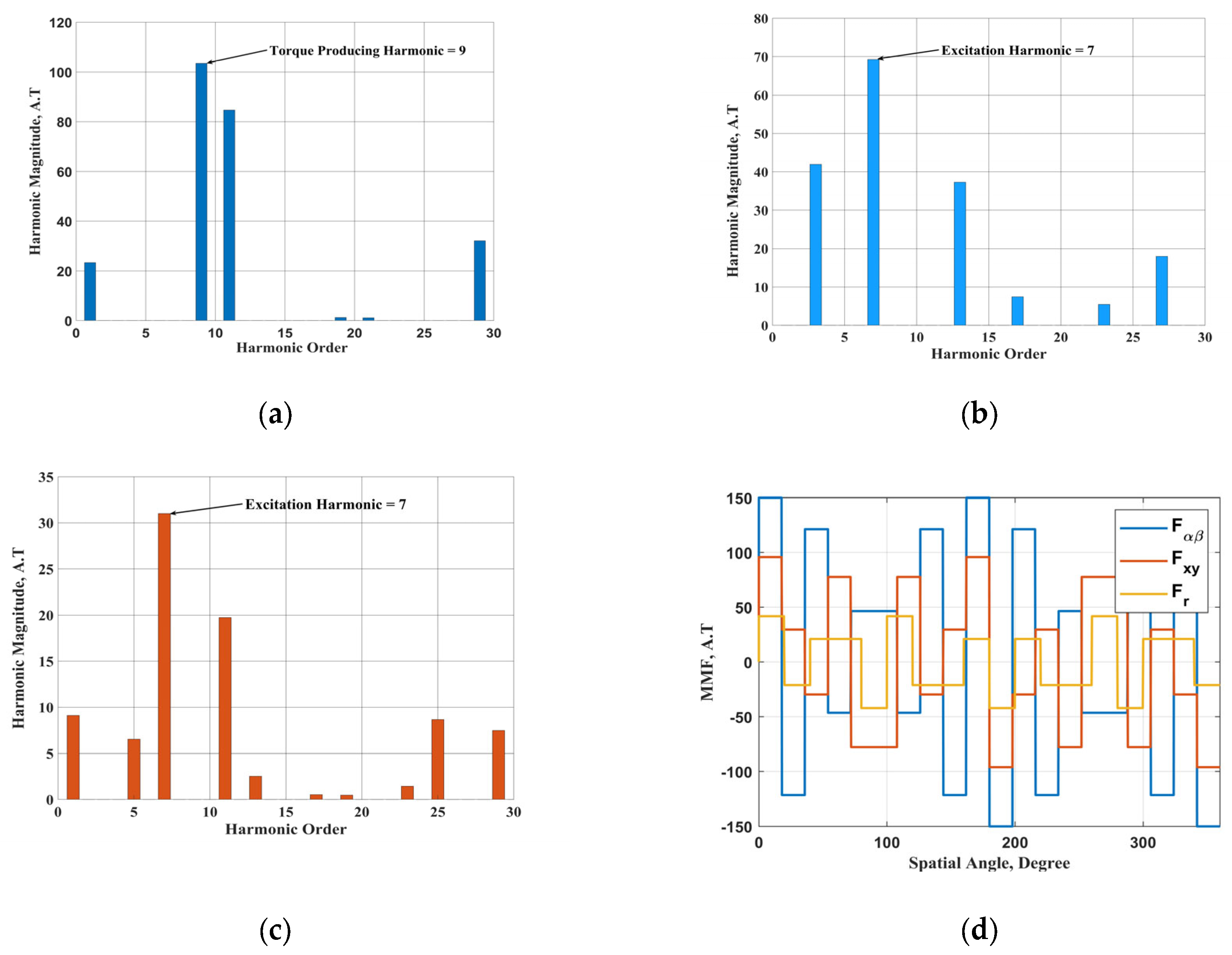
Although the analytical MMF spectra indicate that the relative magnitudes of these shared harmonics are small compared to the dominant 9th and 7th working harmonics, the actual severity of this cross-coupling on field current regulation cannot be definitively judged from the spatial spectrum alone. Therefore, the specific quantitative impact of mechanical loading on the steady-state field winding current must be rigorously evaluated through FEA, as detailed in the Section 4.
2.3. Fault-Tolerant Current Reference Selection Under Single Open-Phase Operation
One of the key advantages of multiphase machines is their ability to continue operating under open-phase faults by appropriately redistributing the currents among the remaining healthy phases. In such conditions, the post-fault phase currents can be selected so that the pre-fault torque-producing condition is preserved as closely as possible, while the remaining degrees of freedom are utilized to satisfy a given optimization criterion. In the available literature [31,32], the most common criteria are maximum torque per ampere, where all remaining healthy phase currents are kept equal, and minimum copper loss (MCL). In the present study, the MCL criterion is adopted because it minimizes the additional copper loss under faulted operation and reduces the undesired interaction between the torque-producing and excitation-related subspaces.
For an isolated-neutral five-phase machine, the zero-sequence component () is zero, reducing the system to four independent current components. In the healthy case where the subscript denotes the healthy condition, the low-frequency fundamental current vector is denoted by the superscript , as it is responsible for torque production, whereas the high-frequency excitation current vector is denoted by the superscript , as it is responsible for rotor harmonic excitation. Therefore, the healthy-case sequence vectors can be written as shown in (4).
Under a single open-phase fault, the number of independent phase currents is reduced by one. Assuming that phase- is open-circuited (), the inverse VSD transformation dictates the following fundamental constraint:
For the torque-producing current set, the primary objective is to preserve the pre-fault current vector, as this vector directly governs electromagnetic torque production. Therefore, the post-fault components are set to and , where the subscript denotes the faulted condition. Applying the open-phase constraint from (5) yields , which directly defines the -axis component as . The only remaining free variable in this scenario is . Under the minimum-loss criterion, the post-fault copper-loss-related objective function is given by:
This function is minimized by setting . This choice not only yields the minimum additional copper loss for the torque-producing current set, but it also minimizes the magnitude of the parasitic subspace component associated with the torque current. By restricting this parasitic component to a stationary -axis term, its influence on the induced harmonic-winding current is significantly reduced.
The same reasoning is applied to the high-frequency excitation current set. The healthy excitation is primarily produced by the balanced subspace current pair (). To preserve the pre-fault excitation conditions, similar to the torque-producing subspace, the post-fault components are selected as and . Under the phase- open condition, the constraint mandates that . To minimize the additional copper loss introduced into the subspace by the excitation current set, the -component is set to . This represents the minimum-loss solution for the excitation current set under the adopted open-phase constraint. This selection effectively preserves the desired balanced high-frequency excitation in the subspace while minimizing the undesired contamination of the torque-producing subspace.
Accordingly, the total post-fault sequence current vectors adopted in this work are summarized in (7).
The total post-fault current reference is then obtained by superimposing the torque-producing and excitation-related components and transforming them back to the phase domain using the inverse VSD transformation. These current references are subsequently utilized in Section 4 to evaluate the fault-tolerant performance of the proposed machine under single open-phase operation.
3. Analytical Sizing and Systematic Machine Design
3.1. Phase A: Preliminary SPM Baseline Sizing and Analytical Equations
To establish the foundational geometric framework, specifically the stator outer diameter, slot–pole combination, and fundamental magnetic loading, a baseline SPM motor is initially designed using Ansys Motor-Cad 15.1.2. The preliminary sizing is conducted according to a predefined set of performance requirements and constraints for the target transportation application [33,34]. Crucially, in this preliminary stage, the machine’s voltage rating is intentionally limited to 50% of the available DC link voltage (). This conservative voltage reserve is essential to ensure adequate headroom for the subsequent injection of the subspace voltage component required to regulate the self-excited magnetizing current. The straightforward magnetic circuit of the SPM topology is utilized at this stage for rapid initial geometric estimation.
The analytical sizing of this baseline machine begins with the fundamental output power equation, which determines the required air-gap volume [35]. The air-gap diameter, , and the effective machine stack length, , are derived as follows:
where is the rated power, is the winding factor, is the target efficiency, is the average air-gap flux density, is the stator electrical loading, and is the electrical frequency. The winding factor is determined based on the mathematical expressions described in [36].
To systematically dimension the machine, the aspect ratio () and the split ratio () are defined to relate the effective length and stator outer diameter () to the air-gap diameter:
Based on fundamental electromagnetic principles and the required flux densities, the stator core dimensions specifically the back-iron thickness (), tooth height (), and tooth width () are computed to prevent magnetic saturation. These are defined by the following expressions:
where and represent the permissible flux densities in the back iron and stator teeth, respectively, is the number of pole pairs, and is the number of stator slots.
3.2. Phase B: Flux-Driven Conversion to WRSM
In the second stage, the analytically derived stator framework and overall specifications are retained, but the baseline permanent magnets are mathematically and structurally replaced with a standard wound-field rotor topology. The primary design objective for this conversion is to replace the magnets with a field winding that produces the same fundamental air-gap flux density () while respecting the strict saturation limits established in the stator teeth and back iron during Phase A. Because field winding coils occupy significantly more volumetric space than permanent magnets to achieve the same magnetic flux density, the standard intermediate diameter of the rotor must be increased when moving from the SPM to the WRSM topology. This geometric shift provides adequate rotor slot area for the main field coils. Consequently, the stack length of the machine is adjusted iteratively in this stage to maintain the required output torque target.
3.3. Phase C: Multiphase Winding Design and SBWRSM Iterative Implementation
Following the WRSM conversion, the architecture is upgraded to the proposed SBWRSM. To achieve high torque density and facilitate self-excitation, an FSCW layout is adopted for the five-phase stator. FSCW topologies represent a highly promising option for SBWRSMs because their MMF distribution inherently contains a rich spectrum of spatial harmonics, which are crucial for wireless power transfer without demanding excessive magnetizing current from the primary supply.
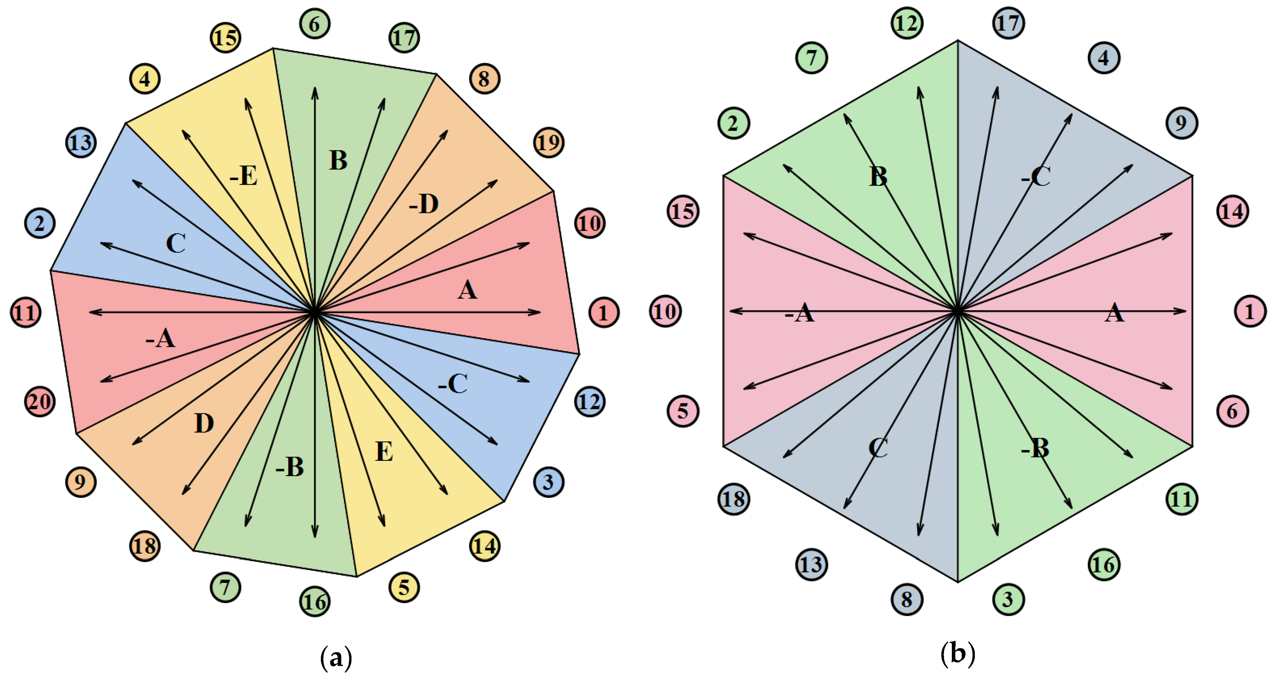
Unlike conventional machine topologies that rely on a single winding set, the proposed architecture requires the precise coordination of three independent windings: the five-phase stator armature, the rotor HW, and the main rotor FW. The design of these windings for the 20s/18p configuration follows a structured harmonic decoupling strategy to make the two required harmonics independent using the star of slots technique. The resulting star of slots for the stator and harmonic windings are shown in Figure 4.
Figure 4.
The 20-slot/18-pole, five-phase motor star of slots. (a) Stator winding star of slots. (b) Rotor harmonic winding star of slots.
Because the machine is driven by a five-phase inverter, the current vectors are decomposed into orthogonal sequence subspaces:
- Fundamental Torque Production ( sequence): When excited by the current sequence, the primary fundamental MMF component is generated. For the chosen 20s/18p configuration, the dominant torque-producing harmonic corresponds to 9 pole pairs (). Consequently, the main rotor FW is explicitly designed as a DC winding with 18 poles to synchronize perfectly with this fundamental field.
- Harmonic Excitation ( sequence): To induce power into the rotor, an auxiliary current sequence is injected. Fourier analysis of the resulting MMF distribution reveals a dominant sub-harmonic component with a distinct pole-pair number (). To ensure maximum induced EMF and strong magnetizing inductance, the rotor HW is specifically configured with to magnetically couple solely with this sequence.
To simplify the construction of the rotating rectifier, the number of phases for the harmonic winding () must be minimized. This is governed by maintaining a balanced symmetry condition [24]:
where is the number of rotor slots allocated for the harmonic winding, represents the greatest common divisor between the rotor slots and the harmonic pole pairs, and is an integer. By satisfying this constraint, the 20s/18p architecture supports efficient operation with improved harmonic decoupling.
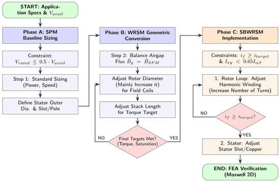
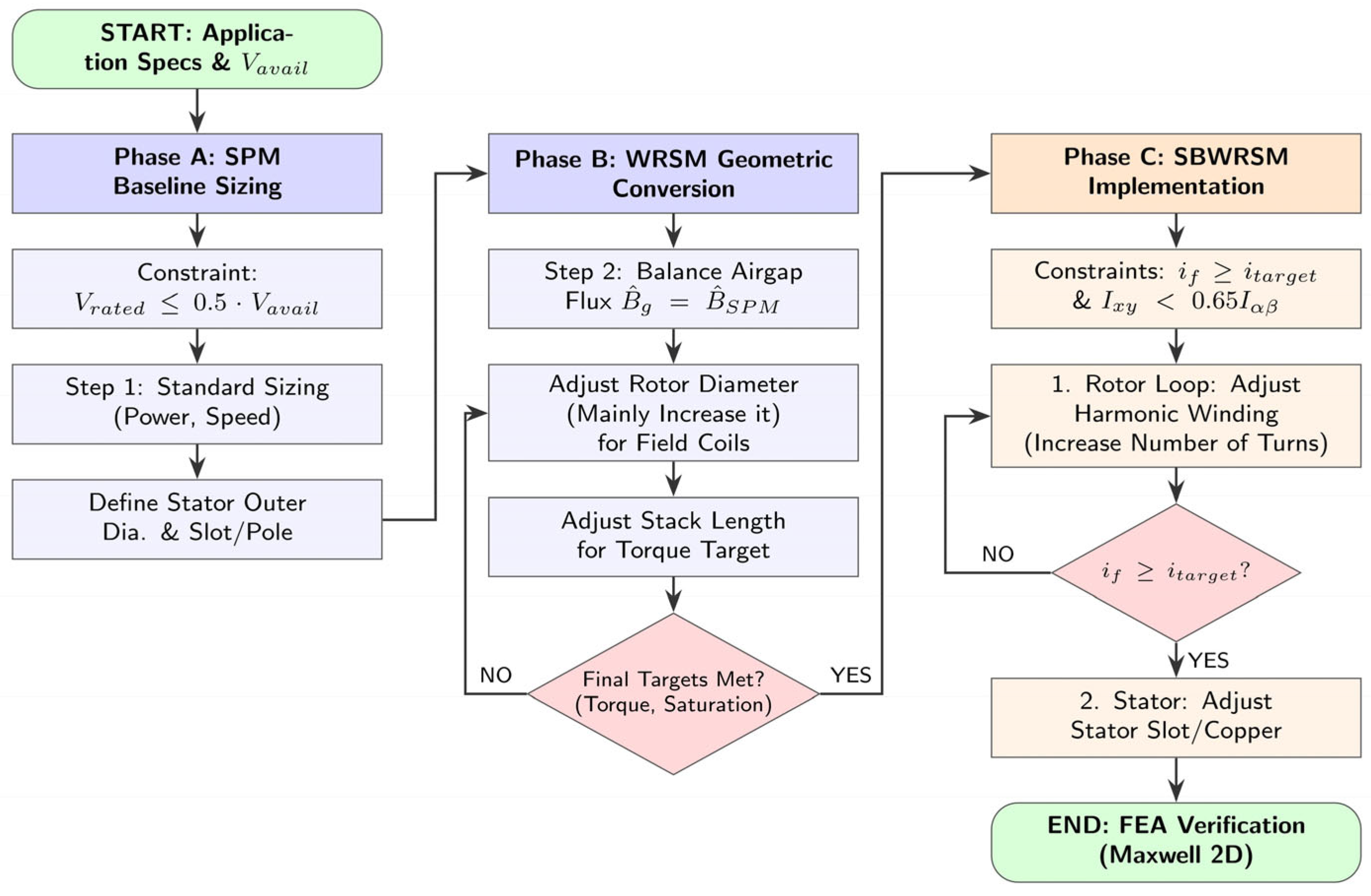
With the winding layout mathematically established, the critical geometric challenge in this final stage is the simultaneous allocation of space for both the main field winding and the specialized harmonic winding within the restricted rotor slots. As shown in the multi-variable iterative loop in the flow chart given by Figure 5, the geometric allocation and turns of the rotor harmonic winding are tuned to increase its volume and induce the required field current () rating. A concurrent constraint is that the magnitude of the stator-injected current component, which drives the excitation, should not exceed 65% of the fundamental torque-producing current component (corresponding to a maximum 20% increase in the RMS phase current). This constraint is vital to minimize copper losses in the stator winding and preserve high torque density.
Figure 5.
Design flow chart of SBWRSM.
When allocating additional copper volume to manage this current, the stator slot dimensions must be adjusted to respect the maximum allowed current density. Through these iterative solutions, the geometric dimensions are optimized until both the torque target and the required field current level are simultaneously achieved. Finally, the complete geometric and analytical model is exported to Ansys Electronics Desktop Maxwell 2D for rigorous finite-element verification, ensuring that the self-excitation dynamic performance is stable and meets specifications.
To improve the traceability of the design methodology shown in Figure 5, the main outputs of each stage are summarized in Table 2, highlighting the transition from the baseline PMSM to the converted WRSM and finally to the proposed SBWRSM.
Table 2.
Evolution of the machine design according to the staged procedure of Figure 5.
4. Finite Element Analysis and Performance Evaluation
4.1. Simulation Setup and Machine Parameters
Building upon the multi-stage conversion and iterative sizing methodology summarized in Table 2, the baseline SPM motor has been successfully transformed into the proposed 20-slot/18-pole five-phase SBWRSM. For this prototype-scale design, self-ventilated air cooling using a shaft-mounted fan is assumed to support the nominal stator current density. To verify the analytical consistency of this design process, Table 3 compares the principal analytical design targets with the final FEA-obtained results and thereby confirms the consistency of the staged design methodology.
Table 3.
Comparison between the main analytical design targets and the final FEA-validated results of the proposed SBWRSM.
As dictated by the self-excited brushless architecture, the customized rotor incorporates two distinct winding sets: an 18-pole main DC field winding designed to synchronize with the fundamental torque-producing MMF, and a 14-pole auxiliary harmonic winding specifically configured to capture the targeted spatial sub-harmonic excitation. To rigorously validate the theoretical operating principles and evaluate the steady-state and dynamic performance of this finalized design, a comprehensive 2D finite-element analysis (FEA) was conducted.
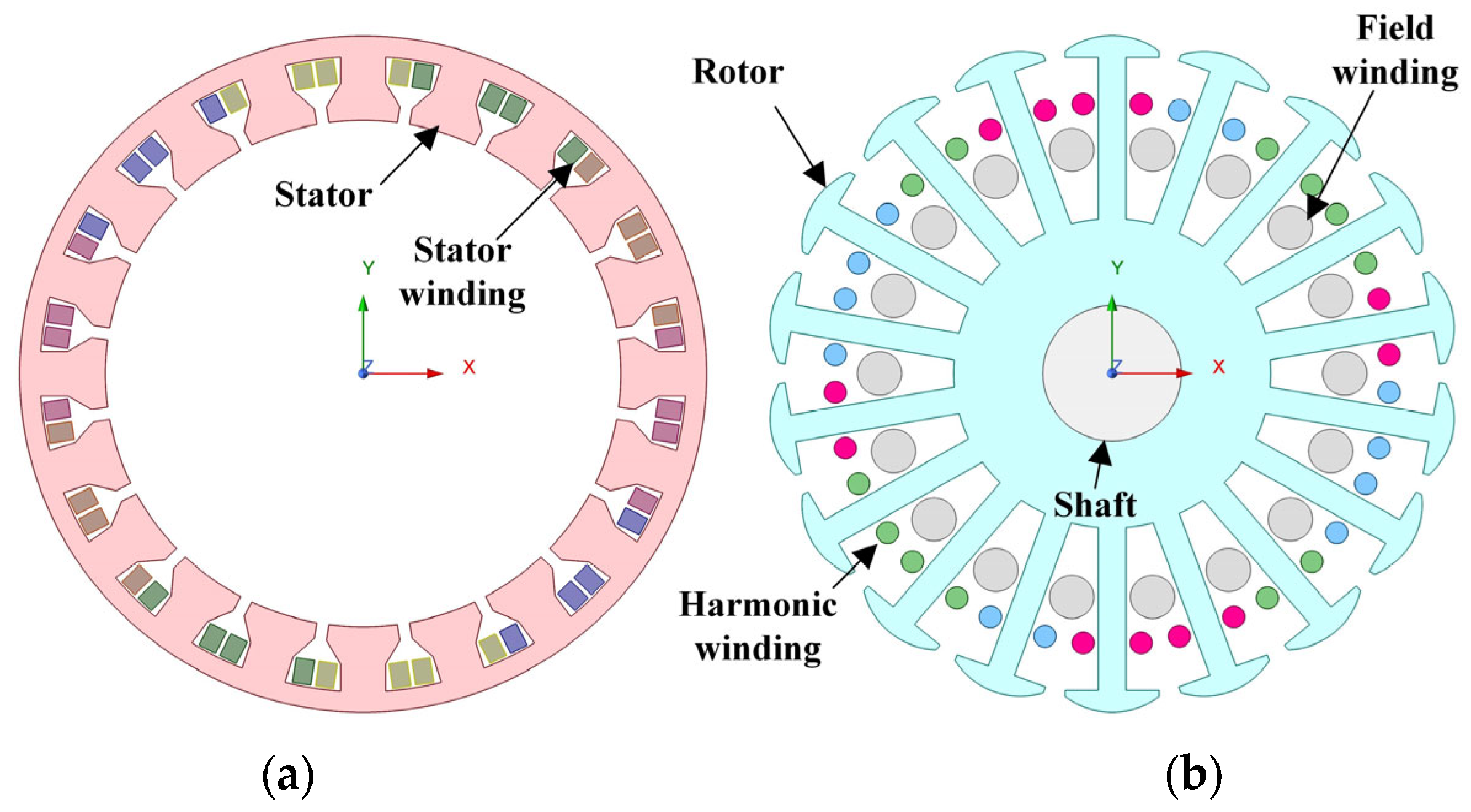
The electromagnetic modeling and transient simulations were executed using Ansys Electronics Desktop (Maxwell 2D), which was directly coupled with an external circuit simulator. This co-simulation environment is essential to accurately model the non-linear switching behavior of the onboard rotating diode rectifier and to capture the precise dynamics of the induced field current. The full cross-sectional FEA model of the developed 20s/18p SBWRSM, highlighting both the stator and rotor winding distributions, is illustrated in Figure 6. The selected 1.8 kW rating is intended as a prototype-scale demonstrator for first-stage electromagnetic validation of the proposed topology and should not be interpreted as a final transportation-machine specification.
Figure 6.
SBWRSM configuration. (a) Stator assembly. (b) Rotor assembly.
As presented in Table 3, the strong correlation across all key electromagnetic parameters validates the accuracy of the proposed analytical sizing equations. Naturally, slight divergences are observed; for instance, the FEA-computed average torque exhibits minor reduction compared to the ideal analytical model. Furthermore, the FEA explicitly captures the anticipated increase in torque ripple, which is a direct and expected consequence of utilizing a sub-harmonic magnetic field for brushless rotor excitation.
4.2. Multiphase Current Injection and Rotor Excitation
To comprehensively evaluate the electromagnetic performance and validate the self-excitation capability of the proposed SBWRSM, five complementary simulation scenarios are investigated in this subsection. First, the steady-state operation is analyzed under nominal conditions. The torque-producing current and the magnetizing subspace current are commanded to their reference values of 10 A and 6.4 A, respectively, to verify the generation of the target 2 A maximum DC field current. Second, a dynamic response scenario is introduced to evaluate the impact of mechanical load step changes on the induced field current. This transient analysis is critical for observing the real-time operational effects of the magnetic cross-coupling discussed analytically in Section 2. Third, a representative single open-phase fault case is considered to assess fault-tolerant operation. Fourth, a parametric sweep is performed to quantify magnetic cross-coupling across the operating range.
By systematically evaluating the average field current under a wide range of combined and injections, a complete surface relationship is derived. This resulting 3D surface explicitly characterizes how the simultaneous application of and dictates , providing a definitive quantitative assessment of the steady-state cross-coupling severity. Finally, an efficiency and winding-loss comparison is carried out between externally excited and self-excited operations.
4.2.1. Steady-State Operation and Magnetic Flux Distribution
The primary objective of the initial FEA simulation is to verify the brushless excitation of the rotor field winding under a maximum-excitation operating case and rated torque and speed. To achieve this, the five-phase stator is supplied with composite phase currents containing both the fundamental torque-producing component () and the sub-harmonic excitation component ().
Based on the design-stage excitation limit, the peak amplitudes are set to 10 A and 6.4 A, with operational electrical frequencies for the fundamental and secondary subspaces of 450 Hz and 1800 Hz, respectively. As established in Section 2, the 1800 Hz injection frequency is specifically selected to ensure sufficient induced EMF in the rotor while minimizing the required magnetizing current as well as voltage reserve.
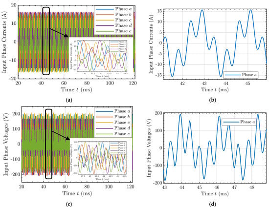
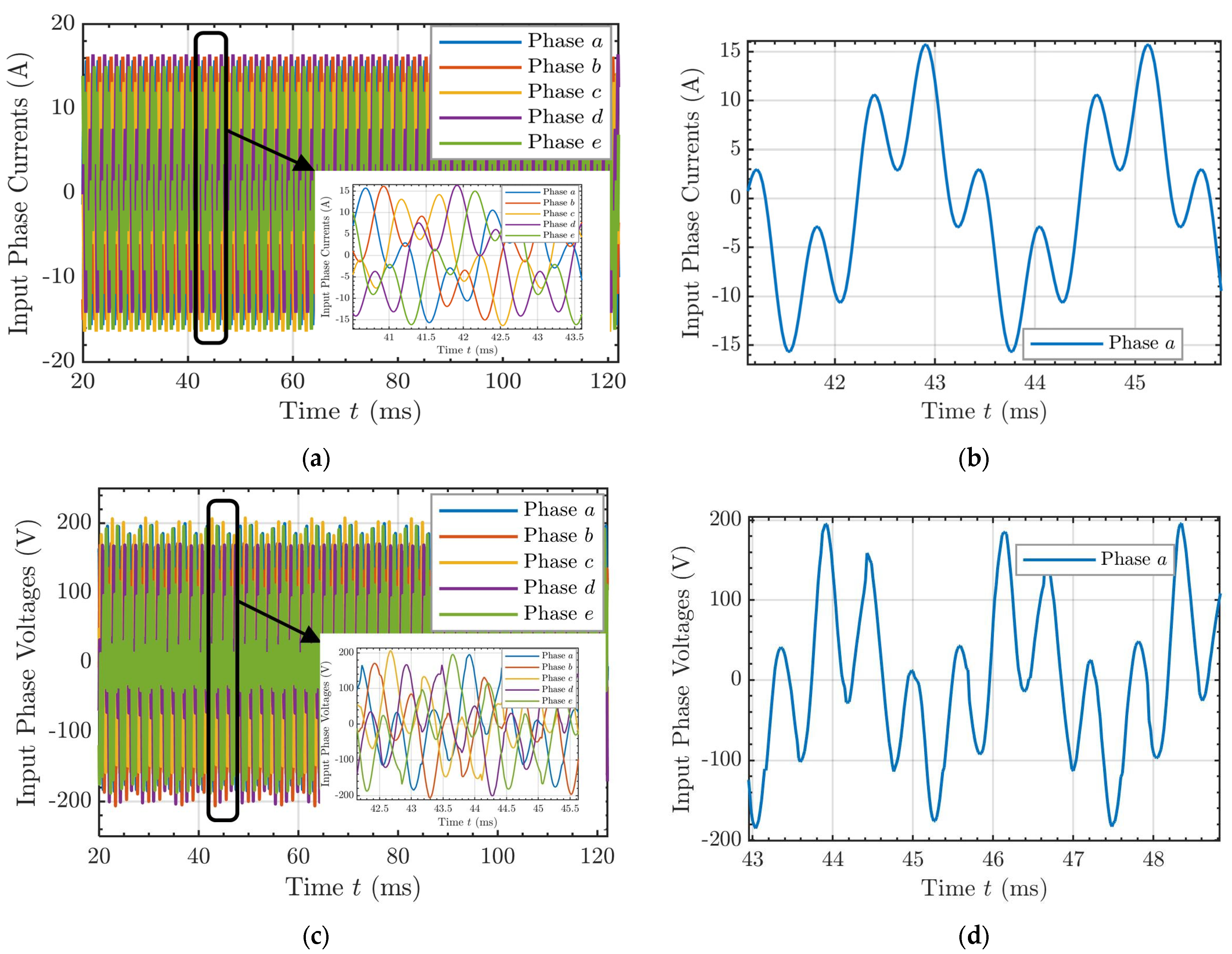
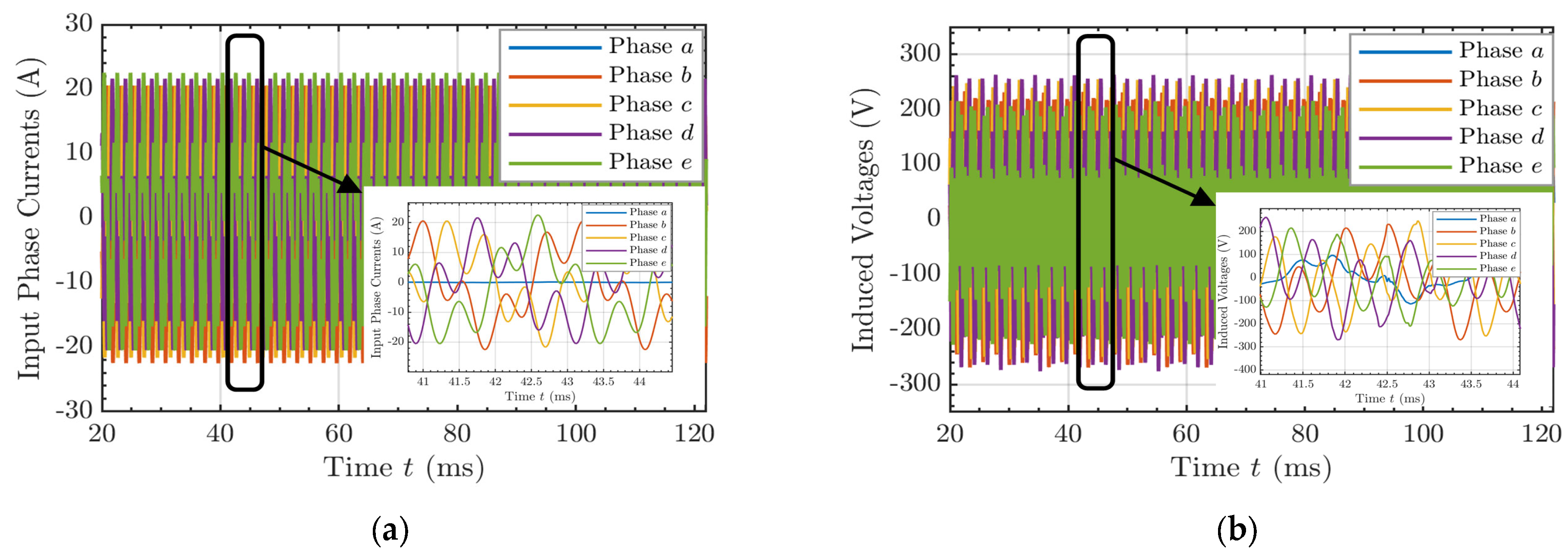
Figure 7 illustrates the simulated steady-state electrical waveforms at the stator terminals under the proposed dual-sequence excitation. The composite five-phase input currents, along with a magnified view of Phase a, are shown in Figure 7a,b, respectively. The injected high frequency current component provides the excitation mechanism for brushless operation, generating a spatial sub-harmonic MMF that crosses the air gap to magnetically couple with the rotor’s HW. Consequently, Figure 7c,d depict the corresponding composite phase voltages required from the inverter to synthesize these currents. The detailed voltage waveform highlights the complex demands placed on the system, as the inverter must simultaneously output the fundamental voltage for torque production alongside the secondary high-frequency voltage for rotor excitation.
Figure 7.
Simulated steady-state electrical waveforms of the stator winding. (a) Five-phase stator currents. (b) Phase a current. (c) Five-phase input voltages. (d) Phase a voltage.
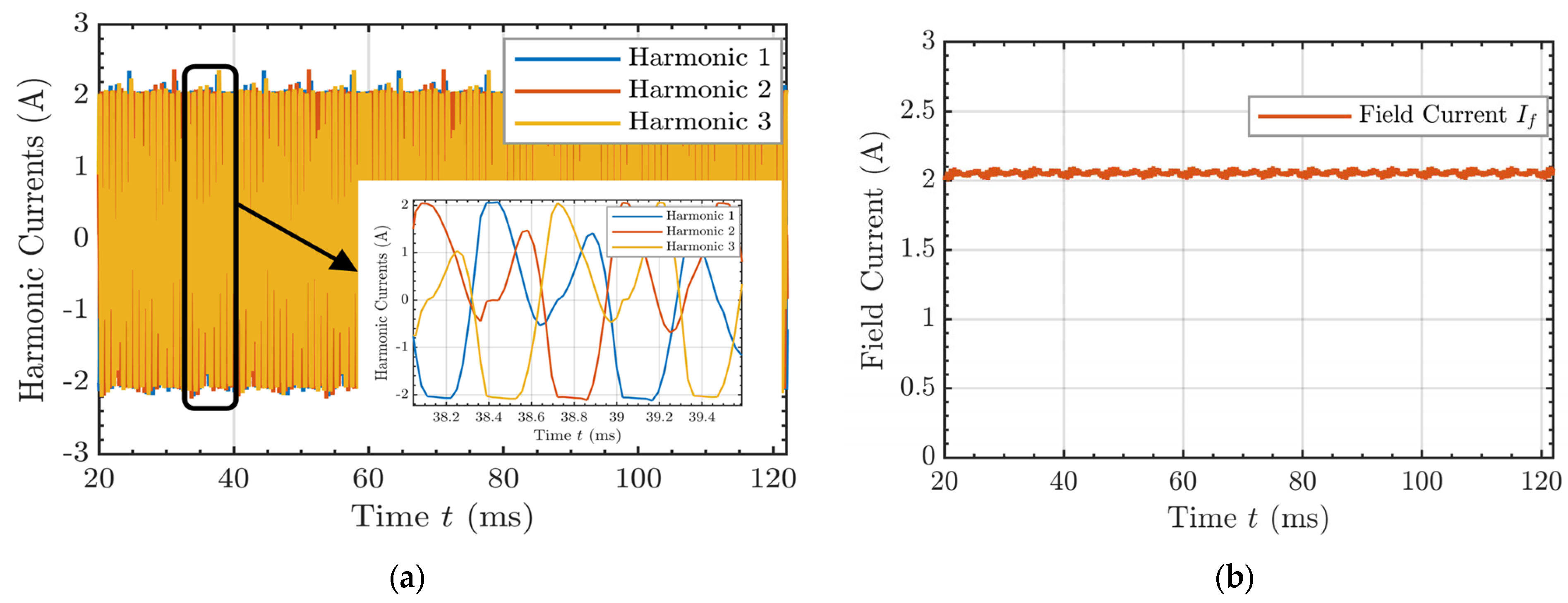
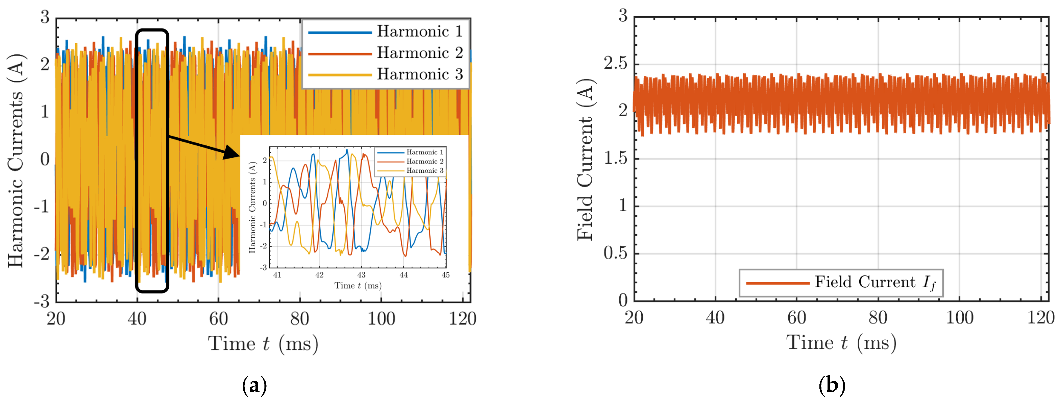
Figure 8a illustrates the three-phase ACs induced within the harmonic circuit. These high-frequency AC waveforms are subsequently rectified by the onboard diode bridge to supply the main field winding. As demonstrated in Figure 8b, after an initial transient build-up phase, the rectified field current stabilizes at the target 2 A DC value. This result validates the analytical sizing of the HW and confirms the viability of the self-excitation mechanism. It should also be noted that this operating condition corresponds to the maximum-excitation design limit and is used here to validate the self-excitation capability of the proposed topology under the highest intended field-current level.
Figure 8.
Simulated steady-state rotor currents during self-excited operation. (a) Three-phase AC induced within the rotor’s HW. (b) The rectified DC field current.
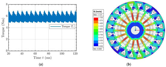
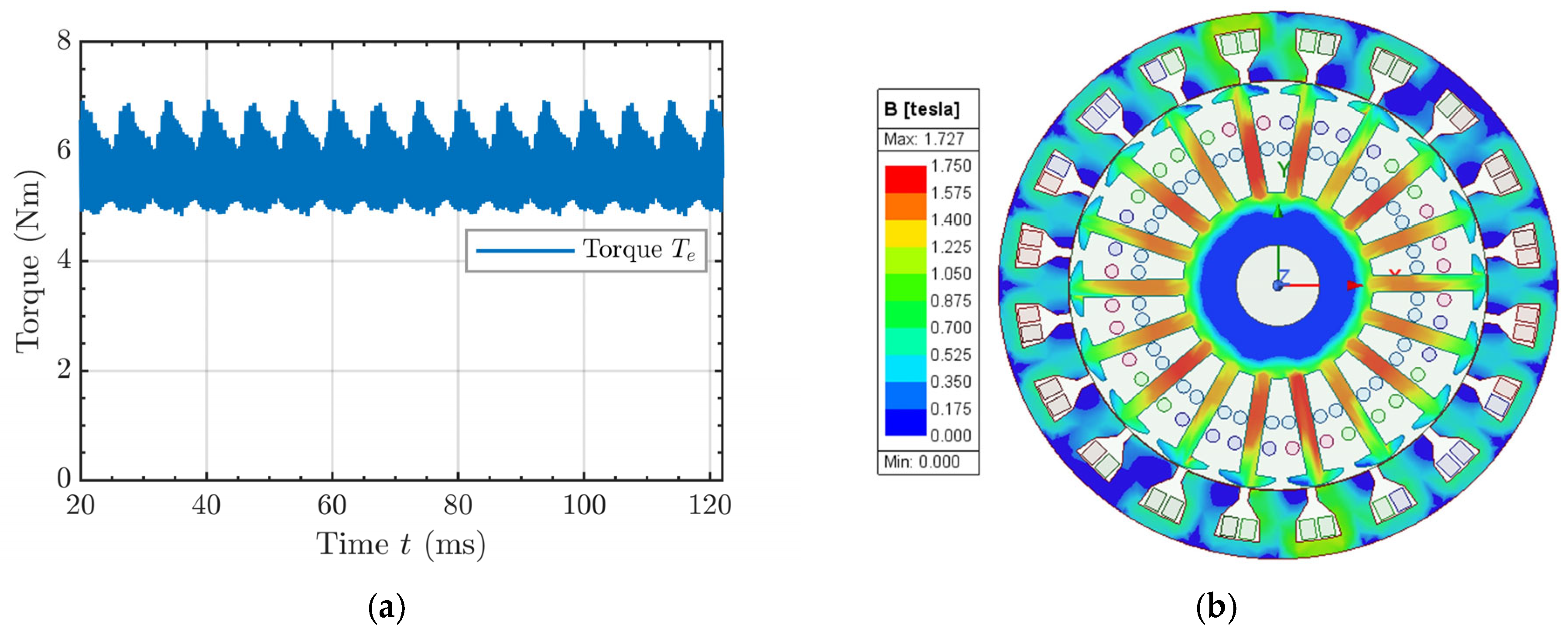
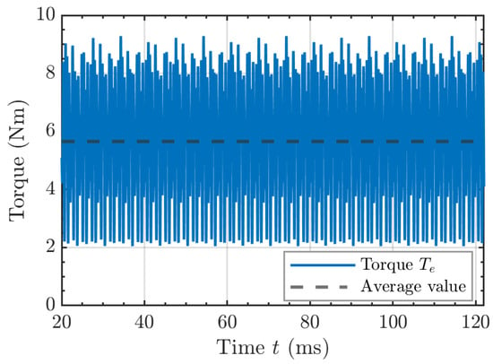
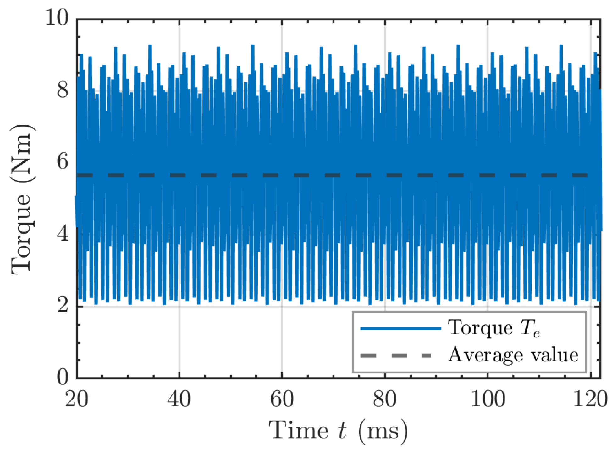
With the nominal field current fully established, the 18-pole rotor flux interacts with the fundamental 18-pole stator MMF to generate electromagnetic torque. The steady-state torque profile under these rated conditions is presented in Figure 9a, yielding an average torque of 5.7 Nm. The observable torque ripple in the steady-state waveform is primarily attributed to standard stator slotting effects combined with the magnetic cross-coupling of the 11th spatial harmonic identified during the MMF spectrum analysis.
Figure 9.
(a) Electromagnetic torque profile. (b) Cross-sectional magnetic flux density distribution.
Finally, to evaluate the structural viability of the electromagnetic design, the magnetic flux density distribution across the machine cross-section was mapped under rated steady-state operation. As shown in Figure 9b, the peak flux density reaches 1.73 T, localized primarily within the stator teeth and rotor yokes. This distribution demonstrates an effective utilization of the core material operating near the knee of the B-H curve thereby maximizing power density without driving the machine into severe, loss-inducing magnetic saturation.
4.2.2. Dynamic Response and Flux Regulation
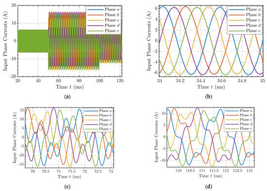
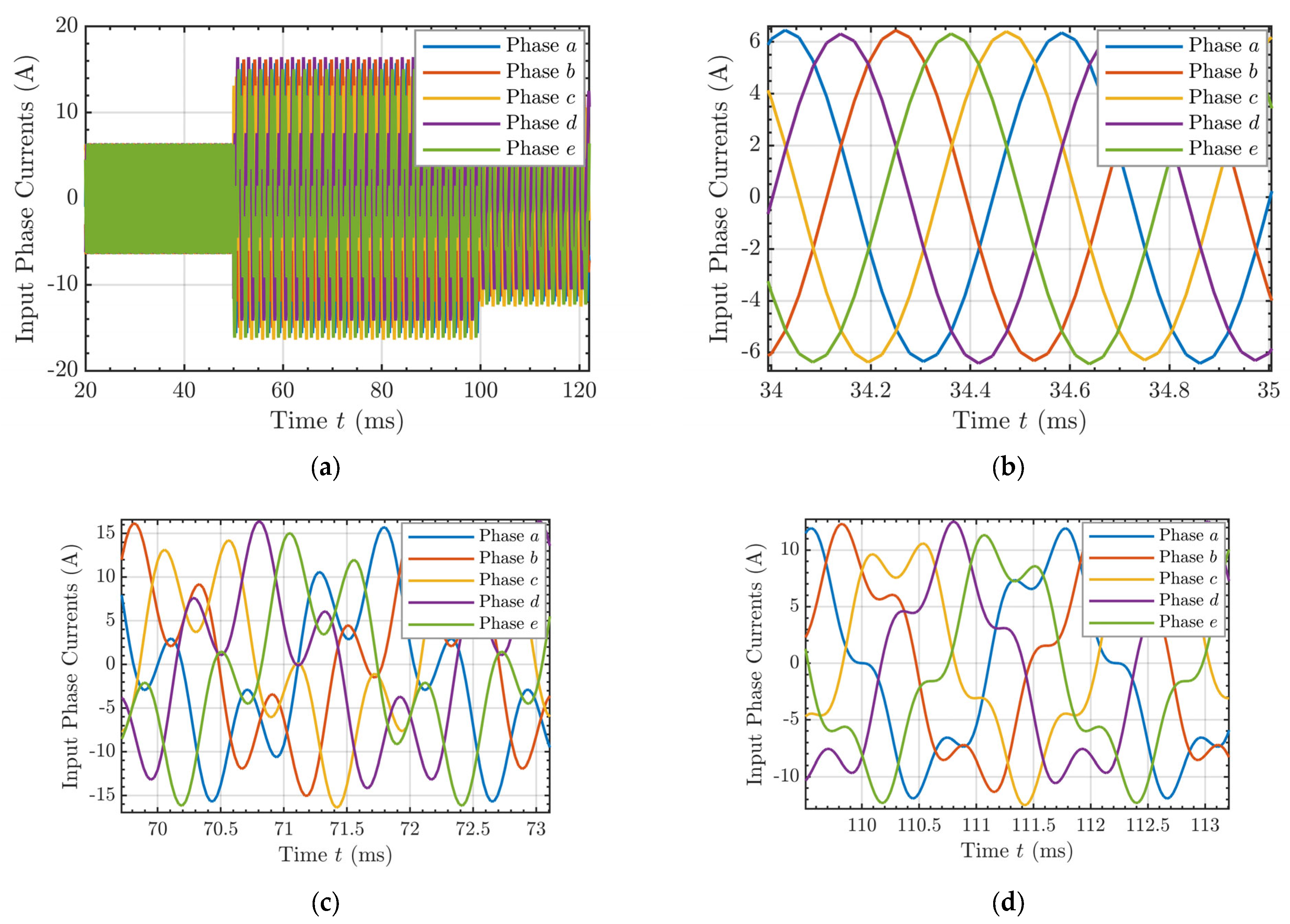
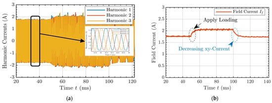
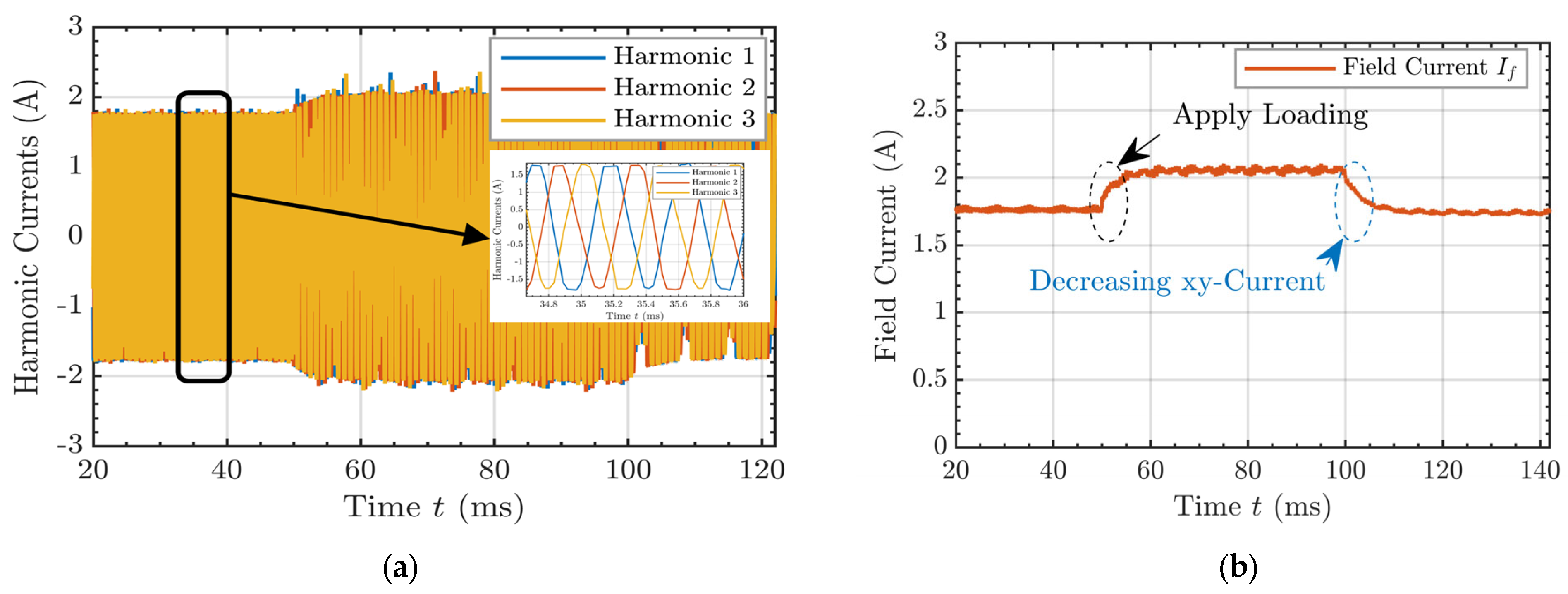
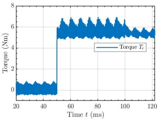
Beyond steady-state operation, a primary advantage of the proposed SBWRSM topology is its capability for independent rotor flux regulation. To evaluate this feature, a dynamic transient simulation was performed to observe the system’s response to step changes in the load and active field control commands. The resulting dynamic profiles for the phase currents, induced harmonic currents, rectified field current, and electromagnetic torque are shown in Figure 10, Figure 11 and Figure 12, respectively.
Figure 10.
Dynamic transient response of the stator phase currents under load stepping and active flux regulation. (a) The five-phase input currents. (b) Pure xy excitation currents prior to load application (). (c) Superimposed composite currents during rated load operation (). (d) Composite currents during active field weakening via -subspace reduction ().
Figure 11.
Dynamic response of the rotor excitation circuit to sudden load variations and active flux control. (a) The induced HW currents. (b) Corresponding variations in the rectified DC field current.
Figure 12.
Dynamic electromagnetic torque response to step changes in the fundamental and sub-harmonic stator currents.
The simulation sequence is divided into three distinct operational stages:
Initial Excitation (): During this initial period, the stator is supplied solely with the rated excitation sequence, keeping the fundamental torque-producing component at zero. The induced high-frequency ACs in the harmonic winding are rectified by the onboard diode bridge, allowing the rotor field current to gradually build up and stabilize at approximately 1.7 A. Because no fundamental current is injected, the electromagnetic torque remains at zero.
Load Step Application (): A mechanical load step is simulated by abruptly injecting the rated current into the stator. As identified during the analytical MMF spectral analysis in Section 2, the shared spatial harmonics between the two VSD subspaces cause a degree of magnetic cross-coupling. Figure 11b demonstrates that in this specific 20s/18p design, the cross-coupling operates constructively; the addition of the fundamental air-gap flux assists the excitation circuit, further increasing the induced field current from 1.7 A to its rated steady-state value of 2 A. In response to the fundamental current injection, the machine develops an average electromagnetic torque of approximately 5.7 Nm, maintaining a stable rotor field without experiencing transient excitation collapse.
Active Flux Regulation (): To verify the independent flux control capability, the amplitude of the excitation current is intentionally reduced to 2.5 A at , while the torque-producing current is maintained at its rated value. The rotor field current smoothly tracks this command, dropping back to 1.7 A. Because the developed electromagnetic torque is directly proportional to the rotor field flux, the average torque exhibits a corresponding reduction, settling at approximately 5 Nm as shown in Figure 12. Furthermore, as observed in the torque profile, reducing the current component notably decreases the amplitude of the induced torque ripple. This behavior suggests the potential existence of an optimal excitation current ratio that minimizes torque pulsations while maintaining the required average torque. A detailed investigation into optimal current injection strategies for torque ripple mitigation falls outside the scope of this study and is deferred to future work.
These dynamic transitions confirm that adjusting the current magnitude enables direct, real-time scaling of the rotor field strength. Consequently, the proposed 20s/18p SBWRSM shows the capability for field-weakening operation over an extended speed range, offering flux-control flexibility comparable to complex dual-inverter configurations but utilizing a single, compact multiphase drive.
4.2.3. Post-Fault Operation
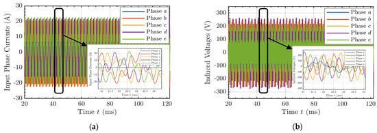
To validate the mathematical framework derived in Section 2.3, a single open-phase fault in phase- was introduced into the FEA co-simulation environment. The present study focuses on the steady-state post-fault operating condition; the detailed transient control transition from healthy to post-fault operation is not explicitly investigated here, since fault transition management in multiphase drives is already a well-established topic and lies outside the scope of this work. As illustrated in the composite and detailed views of the stator phase currents in Figure 13a, the system immediately transitions from a balanced five-phase state to the MCL fault-tolerant scenario. Upon the loss of Phase-A (), the remaining four healthy phases dynamically redistribute their amplitudes and phase angles to compensate. Because the MCL strategy superimposes modified fundamental and high-frequency sequences, the resulting post-fault current waveforms become asymmetric and distorted.
Figure 13.
Stator phase currents and voltages under a single open-phase fault phase-, employing the MCL control strategy. (a) Complete currents profile. (b) Full voltages profile.
Consequently, this asymmetric current redistribution places uneven demands on the inverter. As shown in the phase-voltage waveforms of Figure 13b, the peak voltage requirements for the remaining healthy phases increase notably post-fault. This highlights a critical design consideration: while the MCL strategy successfully minimizes the extra thermal burden on the stator windings, sufficient DC-bus voltage margin must be reserved during the initial machine sizing to accommodate the elevated voltage peaks required during fault-tolerant operation. To avoid overvoltage operation under such conditions, the achievable rated speed may need to be limited, and field-weakening operation may have to be initiated at a speed lower than 3000 rpm, which in turn would imply operation under a reduced load-torque condition.
A primary concern in self-excited brushless machines under fault conditions is the potential collapse of the rotor field due to MMF distortion. However, the simulation results demonstrate the robustness of the proposed topology. Figure 14a displays the induced currents within the rotor’s HW. Despite the unbalance in the stator MMF caused by the open phase, the harmonic winding successfully continues to capture the sub-harmonic spatial flux, sustaining the necessary high-frequency AC. Most importantly, as depicted in Figure 14b, the rectified main DC field current () maintains its rated value of approximately 2.0 A.
Figure 14.
Simulated steady-state rotor currents during fault-tolerant operation. (a) Three-phase AC induced within the rotor’s HW. (b) The rectified DC field current.
This outcome directly validates the analytical hypothesis from Section 2.3: by appropriately selecting the post-fault sequence-current components according to the MCL criterion, the controller preserves the required excitation conditions and ensures uninterrupted wireless power transfer to the rotor even under asymmetrical operation.
The ultimate objective of the fault-tolerant strategy is to maintain mechanical output, so as demonstrated by the torque profile in Figure 15, the average electromagnetic torque is successfully preserved at its rated target of 5.7 Nm following the phase- fault. The preservation of the average torque confirms that the and current references were accurately reshaped to maintain the fundamental rotating MMF.
Figure 15.
Electromagnetic torque profile under the phase- open-circuit fault.
However, as anticipated in multiphase fault-tolerant theory, this sustained average torque comes at the performance cost of increased torque ripple. Post-fault, the torque ripple exhibits a substantial increase. Nonetheless, for high-reliability applications, this increase in torque ripple is an entirely acceptable engineering trade-off for the ability to sustain rated torque and continuous self-excitation during emergency operations.
4.2.4. Parametric Analysis of Magnetic Cross-Coupling
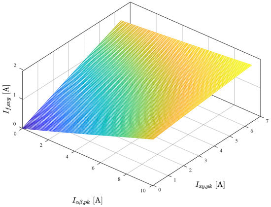
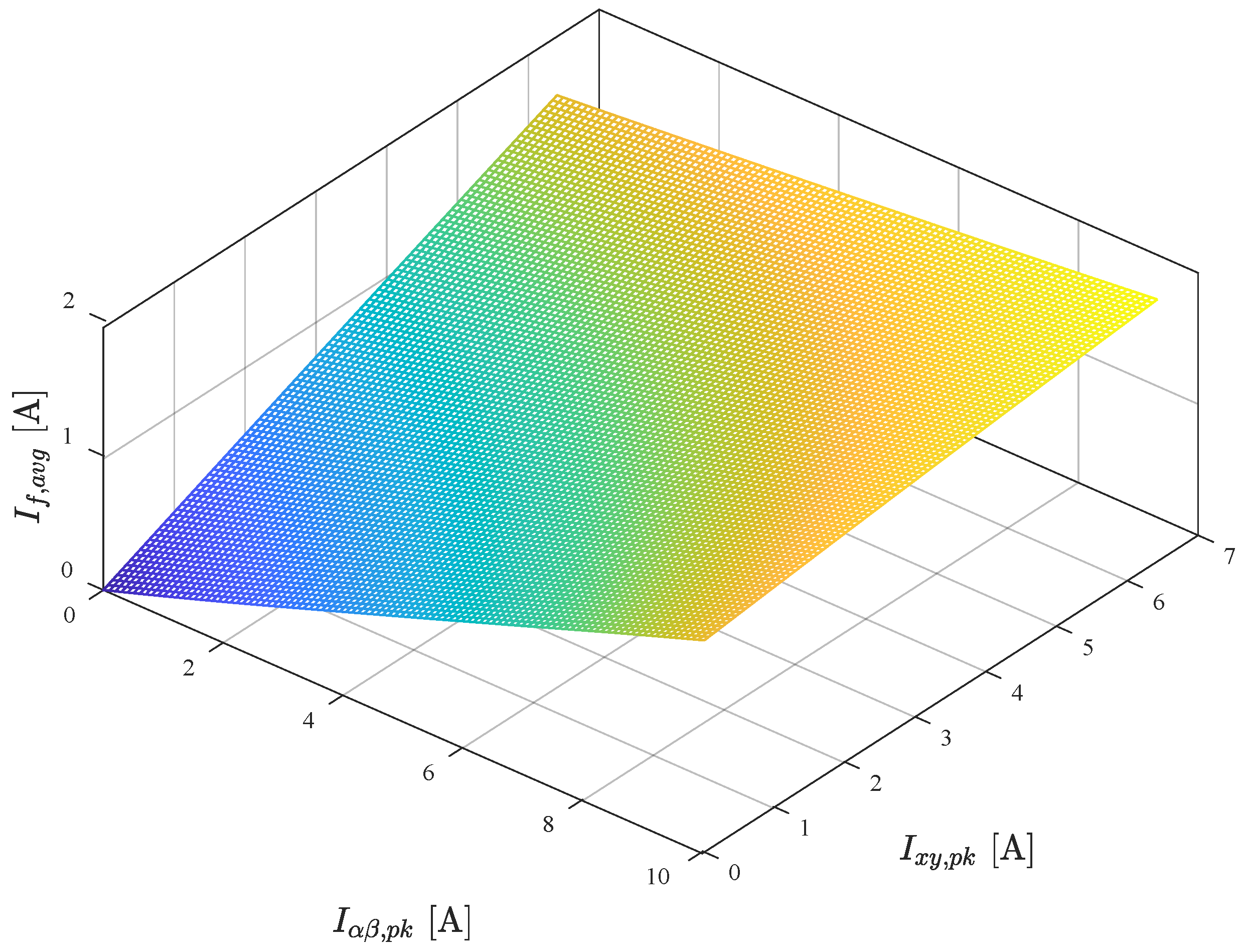
While the dynamic transient simulations confirmed effective independent control of the motor, they also indicated a non-ideal interaction between the torque-producing and excitation fields during mechanical loading. To evaluate this cross-coupling effect across the machine’s full operational envelope, a parametric sweep was performed using FEA. The analysis maps the average rectified rotor field current () over a range of steady-state operating points. The generated 3D surface map, representing the dependency of the induced rotor field current on the simultaneous injection of both spatial sequences, is shown in Figure 16.
Figure 16.
A 3D surface map of the average rectified rotor field current () as a function of fundamental torque-producing current () and sub-harmonic excitation current ().
To derive a precise mathematical representation of the field current dependency, the discrete FEA data points from the generated surface were analytically approximated using a second-order polynomial equation. The established relationship between the composite stator currents and the resulting average induced field current is defined by the following curve-fitting model:
The five fitting gains, determined using MATLAB 2019a curve-fitting toolbox, are summarized in Table 4.
Table 4.
Evaluated curve-fitting coefficients for the steady-state field current approximation.
Analyzing the physical meaning of these numerical coefficients provides a quantitative assessment of the cross-coupling mechanism:
- Primary Excitation Gain: The term is the most dominant coefficient with a value of 0.247. This positive linear gain explicitly confirms that the sub-harmonic sequence is the primary driver of rotor field excitation. Its large positive value validates the fundamental design objective of the proposed topology.
- Constructive Cross-Coupling Term: A notable finding from the parametric sweep is the value of the linear coefficient , which is 0.153. This positive gain provides the mathematical proof that the torque-producing fundamental current independently and constructively contributes to the field excitation. Increasing autonomously raises , directly reinforcing the qualitative constructive excitation discussed in Section 2.
- Non-Linear Saturation Effects: The small positive values obtained for the quadratic terms ( and ) indicate a slight non-linear amplification of the induced field current when each sequence operates independently at higher magnitudes. However, the negative interaction term () reveals a critical physical constraint: when high-amplitude and currents are applied simultaneously, their superimposed MMF leads to localized magnetic cross-saturation within the core. This interaction mildly counteracts the independent constructive effects, dampening the overall field current increase under combined heavy loading.
It is important to contextualize these FEA and curve-fitting results within the broader spectrum of physical multiphase machine behavior. A recent experimental assessment of a five-phase machine with distributed winding [30] demonstrates that increasing the fundamental current can induce destructive cross-coupling, ultimately leading to a drop in the field current. However, it is critical to recognize that the machine in [30] utilized a distributed winding architecture, whereas the proposed topology employs a FSCW. The stark divergence between the destructive coupling observed in [30] and the constructive excitation mapped in Figure 16 indicates that the nature of magnetic cross-coupling is fundamentally dictated by the specific slot–pole combination and the resulting spatial harmonic spectrum of the winding layout.
Consequently, cross-coupling behavior cannot be broadly generalized across different self-excited machine topologies and must be rigorously investigated on a case-by-case basis. Regardless of whether a specific design exhibits constructive or destructive coupling, this inherent load-dependent flux variation underscores the requirement for active, load-adaptive field current regulation. As demonstrated in the dynamic response evaluation, real-time compensation within the FOC scheme remains strictly necessary to counteract these non-ideal VSD coupling effects and maintain a consistent flux linkage across the torque-speed operational envelope.
4.2.5. Efficiency and Winding Loss Comparison
Before comparing the externally excited and self-excited operating modes, it is first necessary to define the practical rated operating point used in this subsection. As observed previously from the dynamic results in Figure 12, reducing the field current from the maximum-excitation value of A to approximately A leads to a significant reduction in torque ripple while still preserving the required average torque. To maintain the same average torque of about 5.7 Nm at this lower excitation level, the torque-producing current component must be increased only slightly, reaching approximately A.
At the same time, and according to the cross-coupling relation given in Figure 16, the required excitation current is significantly reduced to about A. Since the stator conductor was originally selected with a 20% current reserve, the allowable RMS current limit is about 12 A. This reserve was defined during the initial sizing stage relative to the rated 10 A dq-current level. Therefore, the resulting total RMS current at this operating point remains within the adopted current rating. Accordingly, this point is considered a more representative practical rated operating point for the self-excited machine and is used here for the efficiency and loss comparison. By contrast, the previously considered A case is interpreted as a maximum-excitation validation case.
To assess the electromagnetic impact of the proposed brushless excitation topology, a comparative evaluation was conducted between two operating modes of the same main wound-field machine structure over the same torque-speed operating range. In the first case, the -subspace current was set to zero, the rotor harmonic winding was kept open-circuited, and the main field winding was excited by an external DC source, thereby representing conventional externally excited WRSM operation. In the second case, the -subspace current was injected to excite the rotor harmonic winding, and the induced three-phase AC quantity was rectified to supply the same main field winding, thereby representing the proposed brushless self-excited operation. This comparison therefore isolates the additional electromagnetic penalty associated with brushless excitation, while keeping the main field winding configuration unchanged in both cases.
The overall system efficiency () for both configurations was quantified by evaluating the mechanical output power against the total aggregate losses, namely, copper losses () and core losses (), as expressed in (16). In both operating modes, the efficiency was evaluated using the same definition and under the same output power and speed, so that the influence of the different excitation mechanisms could be compared on a consistent electromagnetic basis.
The total copper loss represents the summation of loss components from both the stator and rotor windings, given by (17), while the core loss is estimated using FEA.
For the conventional externally excited case, the -subspace current and rotor harmonic winding current are zero, and the field winding is supplied directly from an external DC source. Accordingly, the associated losses are limited to the fundamental stator copper loss, the main field-winding copper loss, and the core loss produced by the torque-producing -flux component. In contrast, for the proposed brushless self-excited case, both the -subspace current and the rotor harmonic winding current become nonzero, introducing additional excitation-related losses in the stator, rotor harmonic winding, and core.
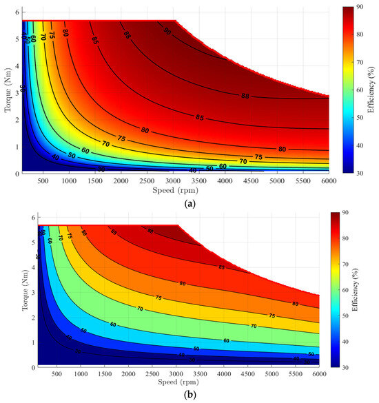
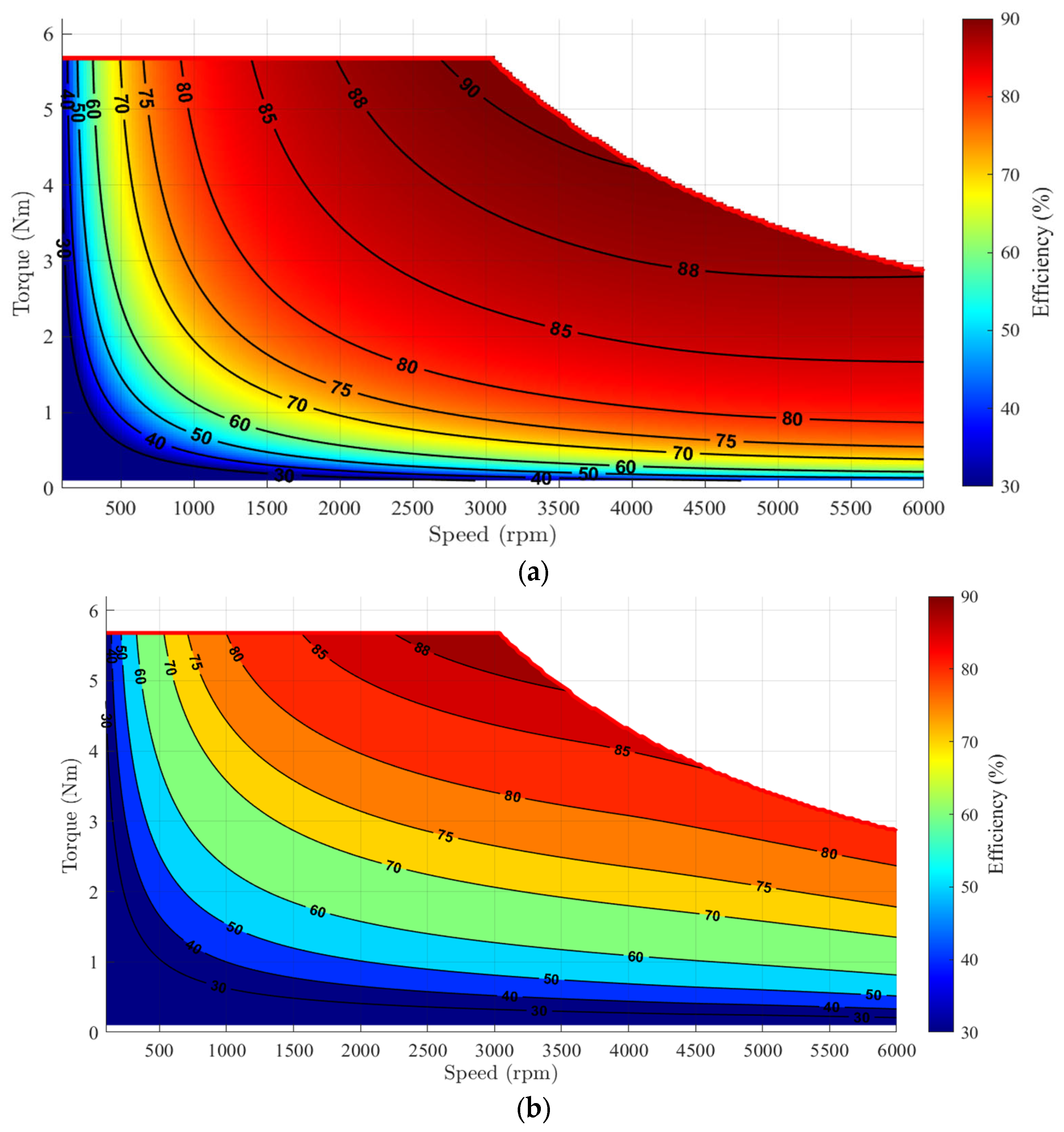
The resulting operating efficiency maps are shown in Figure 17. As expected, the conventional externally excited mode exhibits a broader high-efficiency region, whereas the self-excited mode shows a reduced high-efficiency region because of the additional excitation-related losses. Nevertheless, the two maps remain close to each other, confirming that the proposed self-excited topology preserves the same general operating capability while incurring a moderate efficiency penalty.
Figure 17.
Operating efficiency maps under: (a) conventional externally excited mode; (b) proposed brushless self-excited mode.
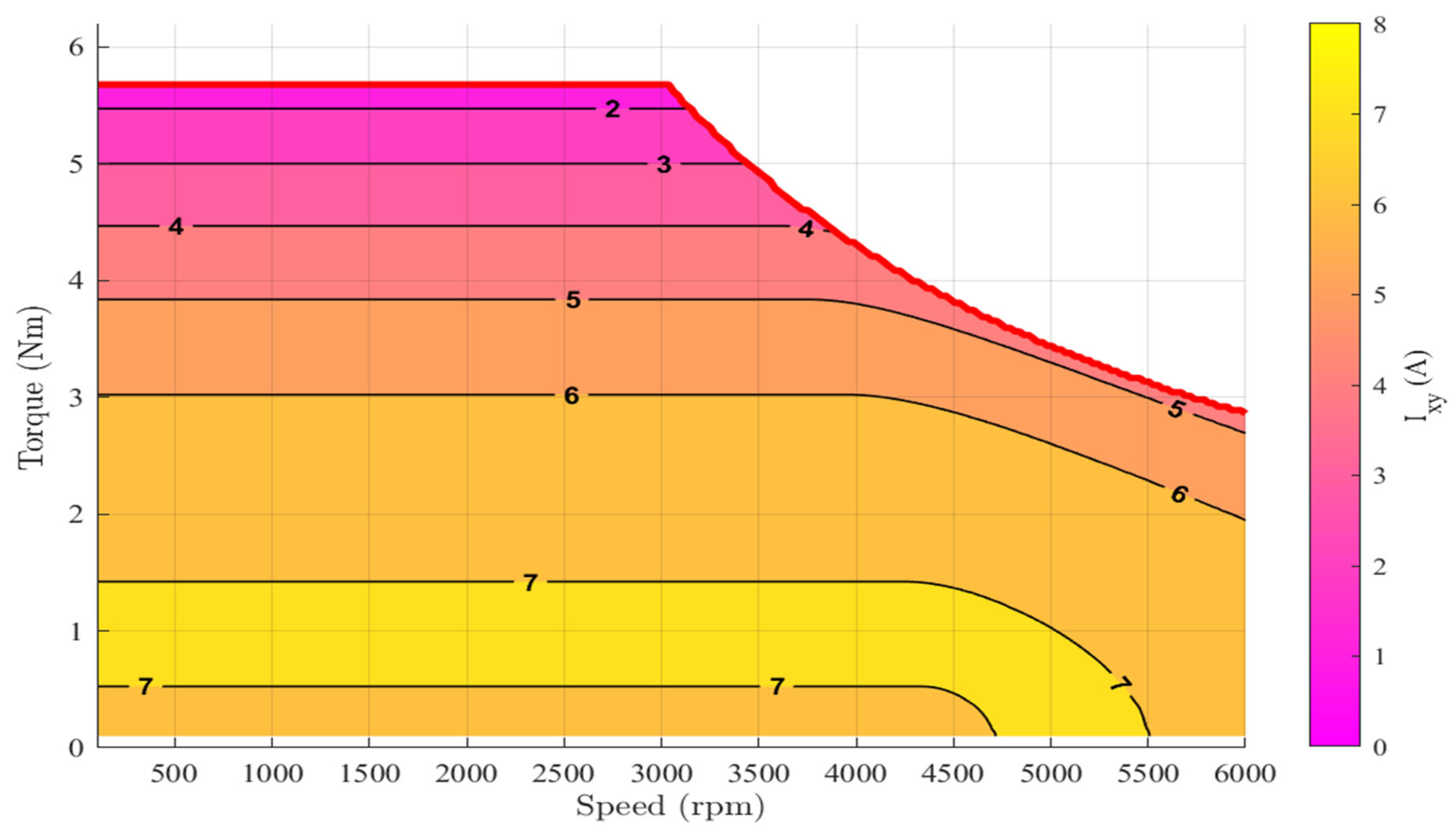
To explain this behavior, the required operating map for the self-excited mode is shown in Figure 18. The map indicates that, near the selected rated operating point, the required excitation current is relatively low, which explains why the self-excited and externally excited machines remain very close in efficiency in that region. By contrast, at lower torque values, if the field current is kept constant, the required increases noticeably as torque decreases. This increase raises the excitation-related stator copper loss, the harmonic-winding copper loss, and the associated high-frequency core loss, causing the efficiency deviation between the two machines to become more pronounced.
Figure 18.
Required operating map for the proposed brushless self-excited mode.
A quantitative comparison at the selected rated operating point is summarized in Table 5. The results show that, at rated load, the efficiency of the self-excited mode remains very close to that of the conventional externally excited mode, reaching 90.2% compared with 90.8% for the externally excited machine. This small difference is consistent with the modest excitation demand at the selected rated point. However, the operating maps also show that this close agreement is mainly limited to the rated region, whereas under lighter-load operation the efficiency deviation becomes more noticeable.
Table 5.
Power loss breakdown and efficiency comparison of conventional vs. self-excited EESM topologies at rated load.
It is worth noting that, in practical wound-field machines, reducing the excitation level at lighter load is a common technique for improving efficiency. Therefore, if were optimized for each torque-speed operating point, the efficiency of the self-excited machine would be expected to improve significantly over a wider operating range. However, such operating-point optimization would require a full joint optimization problem for and , which lies beyond the scope of the present paper and is therefore deferred to future work.
Overall, the results confirm that the efficiency penalty of brushless self-excitation is strongly operating-point-dependent. When the machine is operated near the updated nominal rated point, the excitation effort is relatively modest and the self-excited mode approaches the performance of the conventional externally excited machine. At lower torque values, however, the increasing demand leads to larger additional losses and therefore a wider efficiency deviation. These results show that the proposed topology can retain a practically useful efficiency region while eliminating slip rings and brushes, thereby offering an attractive trade-off between efficiency and maintenance-free operation.
5. Conclusions
This paper presented the analytical design and prototype-scale electromagnetic evaluation of a five-phase 20-slot/18-pole SBWRSM based on a fractional-slot concentrated winding stator. The results confirmed that the proposed topology can achieve brushless self-excitation by assigning the dominant component to torque production and the dominant component to rotor excitation through a dedicated 14-pole, three-phase harmonic winding and an onboard diode rectifier. The machine also exhibited constructive magnetic cross-coupling, in the sense that the torque-producing current assists the excitation circuit under loading, while dynamic simulations confirmed practical flux regulation and stable fault-tolerant operation under a representative single open-phase fault.
The operating-map analysis further showed that the efficiency penalty of brushless self-excitation is strongly operating-point-dependent. Near the selected rated operating point, the self-excited and externally excited machines remain very close in efficiency because the required current is relatively low. At lower torque levels, however, the required increases in order to maintain the same field current, which raises both the excitation-related copper losses and the associated high-frequency core losses, causing a more noticeable efficiency deviation.
These results also indicate that, if the excitation level were optimized for each torque-speed operating point, the efficiency could be improved further over a wider operating range. Overall, the results confirm the prototype-scale electromagnetic feasibility of the proposed 20s/18p topology as a promising magnet-free brushless excitation solution. Future work will include experimental assessment of the prototype and optimal loss-minimization studies based on joint operating-point optimization of and , in addition to 3D/end-effect assessment, thermal and mechanical analysis, inverter-loss modelling, and broader torque-speed/field-weakening evaluation.
Author Contributions
Conceptualization, H.T.A., A.S.A.-K. and S.A.; methodology, H.T.A. and A.S.A.-K.; software, H.T.A.; validation, H.T.A., A.S.A.-K., T.A.S. and S.A.; formal analysis, H.T.A. and A.S.A.-K.; investigation, H.T.A.; resources, A.S.A.-K. and S.A.; data curation, H.T.A.; writing—original draft preparation, H.T.A.; writing—review and editing, A.S.A.-K., T.A.S. and S.A.; visualization, H.T.A.; supervision, A.S.A.-K., T.A.S. and S.A.; project administration, A.S.A.-K. and S.A.; funding acquisition, S.A. All authors have read and agreed to the published version of the manuscript.
Funding
This research was funded by the Ministry of Higher Education, Research and Innovation, Oman, through the Block Funding Program—Research Grant (RG), Call 2025, grant number RC/RG/ENG/ECE/25/460.
Data Availability Statement
The original contributions presented in this study are included in the article. Further inquiries can be directed to the corresponding author.
Conflicts of Interest
The authors declare no conflicts of interest.
Abbreviations
The following abbreviations are used in this manuscript:
| WRSMs | wound-rotor synchronous machines |
| EVs | electric vehicles |
| FEA | finite-element analysis |
| PMSMs | Permanent Magnet Synchronous Machines |
| EESMs | electrically excited synchronous machines |
| WPT | wireless power transfer |
| DAB | dual-active-bridge |
| VSD | Vector Space Decomposition |
| FSCW | Fractional-Slot Concentrated Winding |
| MMF | Magneto-Motive Force |
| SBWRSM | self-excited brushless wound-rotor synchronous machine |
| IMs | Induction Machines |
| FEM | finite-element modeling |
| VSI | Voltage Source Inverter |
| FOC | Field-Oriented Control |
| DC | direct current |
| HW | harmonic winding |
| AC | alternating current |
| FW | field winding |
| EMF | electromotive force |
| SPM | surface-mounted permanent magnet |
| MCL | Minimum Copper Loss |
| UMP | Unbalanced magnetic pull |
References
- Zhang, M.; Yuan, M.; Jiang, J. A Comprehensive Review of the Multiphase Motor Drive Topologies for High-Power Electric Vehicle: Current Status, Research Challenges, and Future Trends. IEEE Trans. Transp. Electrif. 2025, 11, 3631–3654. [Google Scholar] [CrossRef] [Scilit]
- Arish, N.; Kamper, M.J.; Wang, R.J. Advancements in electrical marine propulsion technologies: A comprehensive overview. SAIEE Afr. Res. J. 2025, 116, 14–29. [Google Scholar] [CrossRef] [Scilit]
- Yang, Y.; Chen, Y.; Liu, C. A Computationally Efficient Model Predictive Control Energy Management Strategy for Hybrid Vehicles Considering Driving Style. IEEE Access 2025, 13, 58136–58151. [Google Scholar] [CrossRef] [Scilit]
- Wang, B.; Wang, Y.; Zhang, Z.; Tang, M.; Vakil, G.; Yang, T. Review of Fault-Tolerant Permanent Magnet Synchronous Machine Design and Control for Future Aircraft Application. Chin. J. Electr. Eng. 2025, 11, 165–187. [Google Scholar] [CrossRef] [Scilit]
- Yu, Y.; Xie, S.; Chai, F.; Pei, Y.; Zhang, X.; Lee, C.H.T. Analysis and Suppression of Core and PM Losses in Fractional-Slot Permanent Magnet Vernier Machine and PMSM for in-Wheel Application. IEEE Trans. Ind. Appl. 2025, 61, 6305–6316. [Google Scholar] [CrossRef] [Scilit]
- Yang, Y.-J.; Kim, D.-H.; You, Y.-M. Demagnetization Analysis of Interior Permanent Magnet Synchronous Motors Under Realistic Vehicle Driving Conditions. IEEE Access 2026, 14, 6501–6513. [Google Scholar] [CrossRef] [Scilit]
- Niu, L.; Li, X.; Xi, Z. Research on Temperature Rise and Demagnetization Performance of IPMSM Based on Electromagnetic–Thermal Coupling with Typical Working Conditions. World Electr. Veh. J. 2026, 17, 299. [Google Scholar] [CrossRef] [Scilit]
- Boscaglia, L.; Sugumar, H.S.N.; Sharma, N.; Liu, Y. Design and Verification of an Electrically Excited Synchronous Machine Rotor with Direct Oil Cooling for Truck Applications. IEEE Trans. Transp. Electrif. 2025, 11, 236–245. [Google Scholar] [CrossRef] [Scilit]
- Breda, R.; Andrioli, G.; Calligaro, S.; Petrella, R. Extended MTPA and Flux-Weakening Control with Total Copper Loss Minimisation and Transient Torque Compensation for Wound-Rotor Synchronous Machines. In Proceedings of the 2023 IEEE Energy Conversion Congress and Exposition (ECCE), Nashville, TN, USA, 29 October–2 November 2023; pp. 4829–4836. [Google Scholar]
- Liu, X.; Liu, S.; Fu, Z.; Ge, L. A Critical Review of Fault-Tolerant Control for Multiphase PMSM Drive Systems. IEEE Trans. Transp. Electrif. 2025, 11, 13684–13704. [Google Scholar] [CrossRef] [Scilit]
- Tokgoz, F.; Zhu, Z.Q.; Chen, X.; Liu, C.; Yang, L.; Yuan, Y.; Yang, H.; Huang, Y. Feasibility Analysis of Multiphase Machines for Electric Vehicle Applications. IEEE Trans. Ind. Appl. 2025, 61, 9216–9231. [Google Scholar] [CrossRef] [Scilit]
- Li, X.; Tian, Y.; Dai, W.; Dai, J. Three-Phase Decoupling SVPWM-Based Natural Fault-Tolerant Control of Six-Phase Vernier PM Motor with Open-Phase Fault for Reducing Torque Ripple. IEEE J. Emerg. Sel. Top. Power Electron. 2026, 14, 411–421. [Google Scholar] [CrossRef] [Scilit]
- Xu, X.; Hang, J.; Cao, K.; Ding, S.; Wang, W. Unified Open-Phase Fault Diagnosis of Five-Phase PMSM System in Normal Operation and Fault-Tolerant Operation Modes. IEEE Trans. Transp. Electrif. 2025, 11, 12063–12075. [Google Scholar] [CrossRef] [Scilit]
- Chen, C.; Sun, X.; Chen, Z.; Liu, X.; Zhu, Z.Q.; Liao, X. Fault-Tolerant Control with Faulty Phase Winding Currents Compensation for Current Source Inverter-Fed Five-Phase PMSM Under Adjacent Double-Phase Open-Circuit Fault. IEEE Trans. Transp. Electrif. 2025, 11, 7697–7709. [Google Scholar] [CrossRef] [Scilit]
- Hall, R.D.; Roberge, R.P. Carbon brush performance on slip rings. In Proceedings of the Conference Record of 2010 Annual Pulp & Paper Industry Technical Conference, San Antonio, TX, USA, 21–23 June 2010; pp. 1–6. [Google Scholar]
- Morita, N.; Mori, M.; Ueno, T.; Ishikawa, Y. Comparison of Brush Sliding Contact Characteristics between Structure Steel Ring & Stainless Steel Ring for Large AC Motors. In Proceedings of the 54th IEEE Holm Conference on Electrical Contacts 2008, Orlando, FL, USA, 27–29 October 2008; pp. 98–102. [Google Scholar]
- Steyaert, B.W.; Swint, E.; Pennington, W.W.; Preindl, M. Piecewise Affine Modeling of Wound-Rotor Synchronous Machines for Real-Time Motor Control. IEEE Trans. Ind. Electron. 2023, 70, 5571–5580. [Google Scholar] [CrossRef] [Scilit]
- Xie, L.; Yuan, X. A High-Performance Phase-Shift Full-Bridge Converter with a Rotary Transformer for the Field Excitation of Electric Machines. IEEE Trans. Ind. Appl. 2025, 61, 7410–7420. [Google Scholar] [CrossRef] [Scilit]
- Zhang, B.; Jiang, C.Q.; Yang, F.; Chen, C.; Lu, Y.; Zhou, J. An Antirotation Wireless Power Transfer System with a Flexible Magnetic Coupler for Autonomous Underwater Vehicles. IEEE Trans. Power Electron. 2025, 40, 2593–2603. [Google Scholar] [CrossRef] [Scilit]
- Tang, J.; Jiang, B.; Boscaglia, L.; Liu, R.; Lundberg, S.; Liu, Y. High-Frequency Brushless Excitation with Bi-Directional Power Flow for Electrically Excited Synchronous Machines. In Proceedings of the 2024 International Conference on Electrical Machines (ICEM), Torino, Italy, 1–4 September 2024; pp. 1–7. [Google Scholar]
- Jiang, B.; Tang, J.; Liu, Y. Extended-Kalman-Filter-Based Field Current Estimation for Brushless Electrically Excited Synchronous Machines Using Stator Current Measurements. IEEE Trans. Transp. Electrif. 2025, 11, 5042–5054. [Google Scholar] [CrossRef] [Scilit]
- Ul Haq, M.A.; Farooq, H.; Hussain, A.; Kashif, S.A.R. A Novel Brushless Wound Rotor Synchronous Machine Utilizing Inherent Sub-Harmonic Component. IEEE Access 2025, 13, 15683–15693. [Google Scholar] [CrossRef] [Scilit]
- Ayub, M.; Arif, A.; Rehman, A.U.; Nadeem, A.; Sirewal, G.J.; Abido, M.A.; Siddiqi, M.R. Brushless Wound-Field Synchronous Machine Topology with Excellent Rotor Flux Regulation Freedom. Machines 2026, 14, 110. [Google Scholar] [CrossRef] [Scilit]
- Abdel-Wahed, A.T.; Abdel-Khalik, A.S.; Hamdy, R.A.; Hamad, M.S.; Ahmed, S. Self-excited wound rotor synchronous motors for electric vehicles: Techniques and multiphase winding design strategies. Alex. Eng. J. 2025, 123, 271–310. [Google Scholar] [CrossRef] [Scilit]
- Chung, J.; Hofmann, H. Brushless Self-Excited Synchronous Field-Winding Machine with Five- and Higher-Phase Design Using Independently Controlled Spatial Harmonics. IEEE Trans. Energy Convers. 2024, 39, 533–543. [Google Scholar] [CrossRef] [Scilit]
- Levi, E. Multiphase Electric Machines for Variable-Speed Applications. IEEE Trans. Ind. Electron. 2008, 55, 1893–1909. [Google Scholar] [CrossRef] [Scilit]
- Alberti, L.; Bianchi, N. Theory and design of fractional-slot multilayer windings. In Proceedings of the 2011 IEEE Energy Conversion Congress and Exposition; IEEE: Piscataway, NJ, USA, 2011; pp. 3112–3119. [Google Scholar]
- Qiu, H.; Yuan, C.; Ma, X.; Chen, W. Improvement in Performance of Flux-Torque Regulation Hybrid Excitation Machine with Fractional Slot Concentrated Winding. IEEE Trans. Ind. Electron. 2026, 73, 1782–1792. [Google Scholar] [CrossRef] [Scilit]
- Kang, H.; Zhou, L.; Wang, J. Harmonic Winding Factors and MMF Analysis for Five-phase Fractional-slot Concentrated Winding PMSM. J. Int. Conf. Electr. Mach. Syst. 2014, 3, 20–26. [Google Scholar] [CrossRef] [Scilit]
- Abdel-Moneim, M.G.; Ismail, A.; Abdel-Wahed, A.T.; Abdel-Khalik, A.S.; Ahmed, S. Experimental Assessment and Mathematical Modeling of a Self-Excited Wound Rotor Synchronous Motor with Multiphase Stator Design. IEEE Trans. Energy Convers. 2026, 1–13. [Google Scholar] [CrossRef] [Scilit]
- Yepes, A.G.; Gonzalez-Prieto, I.; Lopez, O.; Duran, M.J.; Doval-Gandoy, J. A Comprehensive Survey on Fault Tolerance in Multiphase AC Drives, Part 2: Phase and Switch Open-Circuit Faults. Machines 2022, 10, 221. [Google Scholar] [CrossRef] [Scilit]
- Yepes, A.G.; Lopez, O.; Gonzalez-Prieto, I.; Duran, M.J.; Doval-Gandoy, J. A Comprehensive Survey on Fault Tolerance in Multiphase AC Drives, Part 1: General Overview Considering Multiple Fault Types. Machines 2022, 10, 208. [Google Scholar] [CrossRef] [Scilit]
- Hemeida, A. Electromagnetic and Thermal Design of Axial Flux Permanent Magnet Synchronous Machines. Ph.D. Thesis, Ghent University, Ghent, Belgium, 2017; pp. 127–132. [Google Scholar]
- Pyrhönen, J.; Jokinen, T.; Hrabovcová, V. Design of Rotating Electrical Machines, 2nd ed.; John Wiley & Sons, Ltd.: Chichester, UK, 2013; p. 298. [Google Scholar]
- Surong, H.; Jian, L.; Leonardi, F.; Lipo, T.A. A general approach to sizing and power density equations for comparison of electrical machines. IEEE Trans. Ind. Appl. 1998, 34, 92–97. [Google Scholar] [CrossRef] [Scilit]
- Bianchi, N.; Bolognani, S.; Frare, P. Design Criteria for High-Efficiency SPM Synchronous Motors. IEEE Trans. Energy Convers. 2006, 21, 396–404. [Google Scholar] [CrossRef] [Scilit]

Disclaimer/Publisher’s Note: The statements, opinions and data contained in all publications are solely those of the individual author(s) and contributor(s) and not of MDPI and/or the editor(s). MDPI and/or the editor(s) disclaim responsibility for any injury to people or property resulting from any ideas, methods, instructions or products referred to in the content. |
© 2026 by the authors. Licensee MDPI, Basel, Switzerland. This article is an open access article distributed under the terms and conditions of the Creative Commons Attribution (CC BY) license.