


Abstract
The integration of energy dissipation units into the Modular Multilevel Converter (MMC) enables surplus power dissipation without the need for additional energy dissipation devices outside the converter valve, thereby reducing the cost of the surplus power fault ride-through (FRT) solution. The existing topology integrates energy dissipation units in all submodules (SMs) of the MMC, increasing the difficulty of modification. To address this issue, this paper proposes a single-phase integrated configuration of energy dissipation units, in which only the SMs in the outermost phase unit of the converter valve need to be modified. This configuration simplifies on-site construction and facilitates equipment operation and maintenance. This paper studies the control strategy of the topology and determines the corresponding parameters, which can reduce the number of energy dissipation units that need to be retrofitted while suppressing voltage fluctuations. The feasibility of the scheme is verified through simulations and experiments. Finally, a technical and economic analysis is conducted in terms of the investment cost and control performance of the single-phase MMC with integrated energy dissipation equipment (IEDE-MMC). Compared with the three-phase IEDE-MMC, the investment cost is reduced by 33%, the DC voltage fluctuation range is reduced by 66.7%, and the lower limit of the SM capacitor voltage is raised by 10.8%.
1. Introduction
Offshore wind power Voltage-Source Converter-based High-Voltage Direct-Current (VSC-HVDC) transmission feature low losses, low manufacturing difficulty, and flexible control, making them particularly suitable for the transmission of deep-sea large-capacity wind farms and offering broad engineering prospects [1,2,3,4,5]. At present, the surplus power FRT schemes for such systems can be divided mainly into wind turbine output power adjustment schemes [6,7,8] and surplus power absorption schemes based on energy dissipation devices [9,10]. Owing to their fast response and high control reliability, energy dissipation devices have become a widely used FRT solution in engineering applications. Existing studies on energy dissipation devices mainly focus on installation location, topology, control strategy, and parameter design.
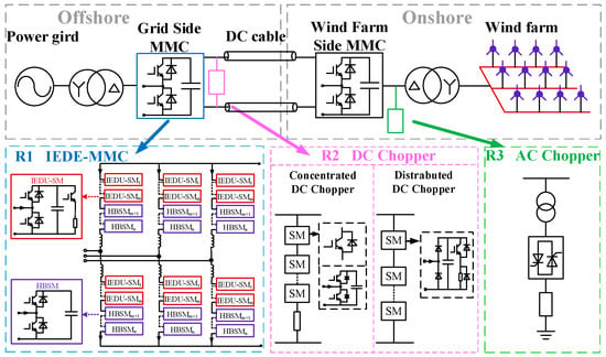
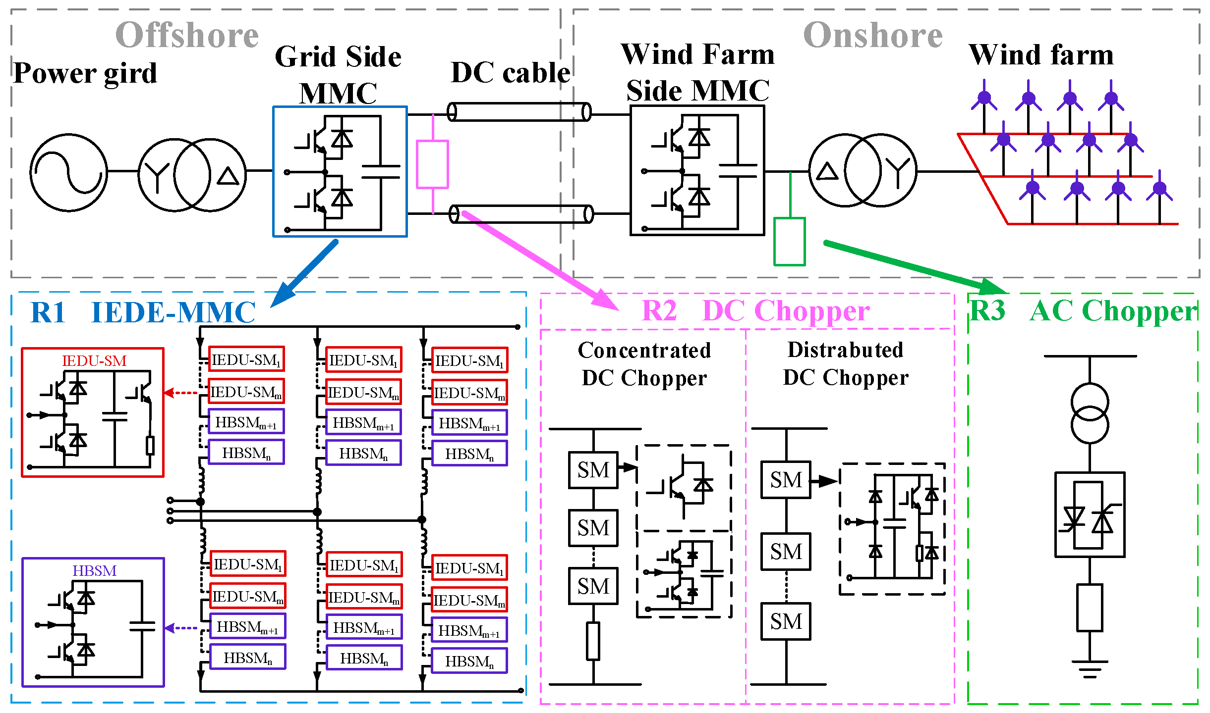
An AC chopper (ACC) installed at the AC outlet of the wind farm is proposed in [11], as shown in Figure 1 (R3), which can directly absorb surplus power from the AC side. However, for offshore platforms, additional ACCs increase the platform weight, installation space, insulation coordination complexity, and water-cooling system burden. A DC chopper (DCC) installed between the positive and negative DC lines is introduced in [12], as shown in Figure 1 (R2). The concentrated DCC can meet the heat dissipation requirements by arranging the resistors outside the valve hall. However, this scheme concentrates the dissipation power in an independent DC dissipation branch, where the power devices and resistors need to withstand high voltage and current stresses. The dynamic voltage sharing of series-connected switching devices, local thermal load, cooling capacity, and additional installation space are its main engineering issues [13]. To address this, a distributed DCC is proposed in [14], which overcomes the shortcomings of the concentrated scheme through modular design. However, this scheme still requires additional modular hardware, communication links, insulation design, and coordinated control, which may still lead to high costs and space requirements in offshore wind power applications. A comparison of ACC and DCC topologies is presented in [15], concluding that DCCs have more obvious development advantages. A DCC with a coupling transformer and a voltage–current double-loop control strategy is proposed in [16] to effectively reduce the disturbance of faults on the DC voltage. Three topologies of DCCs are discussed in [17], along with their control methods and parameter design, to limit the DC overvoltage within the range of 1.02 p.u. to 1.05 p.u. In addition, the DCC is an independent apparatus located outside the converter valve, which introduces a series of issues such as footprint, equipment cost, and technology [18].
Figure 1.
Schematic diagram of grid connection system of offshore wind farm through MMC-HVDC.
The modular design of the MMC provides a more cost-effective way to realize the distributed layout of dissipation resistors. Since the submodules of a modular DCC are structurally similar to traditional MMC submodules, integrating energy dissipation devices into the MMC is a feasible solution. The IEDE-MMC directly integrates the energy dissipation units into the MMC submodules, as shown in Figure 1 (R1). By leveraging the inherent modular structure of the MMC, it eliminates the need for constructing external dissipation valve groups for the dissipation resistors and switching devices, thereby avoiding additional footprint and valve tower construction costs. Meanwhile, the distributed dissipation structure can reduce the voltage-sharing stress of high-voltage series-connected switching devices and can be extended based on the existing MMC water-cooling system. However, the conventional three-phase IEDE-MMC requires the submodules in all three phase arms to be retrofitted, which increases the engineering retrofit complexity, valve section modification workload, and subsequent maintenance difficulty.
To address the above problems, this paper proposes a single-phase IEDE-MMC. In this scheme, Submodules with Integrated Energy Dissipation Units (IEDU-SMs) are configured in only one phase unit, while the other two phases still adopt conventional Half-Bridge Submodules (HBSMs). This structure reduces the number of phase units requiring retrofit, which can simplify on-site installation, shorten the retrofit time, and improve operation and maintenance convenience. For the water-cooling system, the dissipation resistor cooling system is centrally arranged in one phase unit, which makes the cooling pipelines more compact and avoids large-scale modifications to the water-cooling systems of all three valve sections. In terms of cost, the reduced number of IEDU-SMs, auxiliary devices, and installation workload can lower the total investment. Therefore, the single-phase IEDE-MMC is particularly suitable for the retrofitting and upgrading of existing Modular Multilevel Converter based High Voltage Direct Current (MMC-HVDC) converter valves, especially in engineering scenarios with limited retrofit space and outage windows. The comparison of the different schemes is shown in Table 1.
Table 1.
Comparison of various schemes.
The rest of the article is organized as follows. The proposed single-phase IEDE-MMC is introduced in Section 2. In Section 3, the design method of the single-phase IEDE-MMC is discussed. Section 4 verifies the effectiveness of the simulation platform and experimental platform in terms of single-phase topology and control strategy. Section 5 is the technical and economic analysis of single-phase topology and control strategy. Finally, conclusions are summarized in Section 6.
2. Proposed Single-Phase IEDE-MMC
2.1. Topology of Single-Phase IEDE-MMC
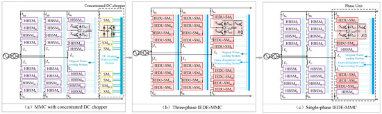
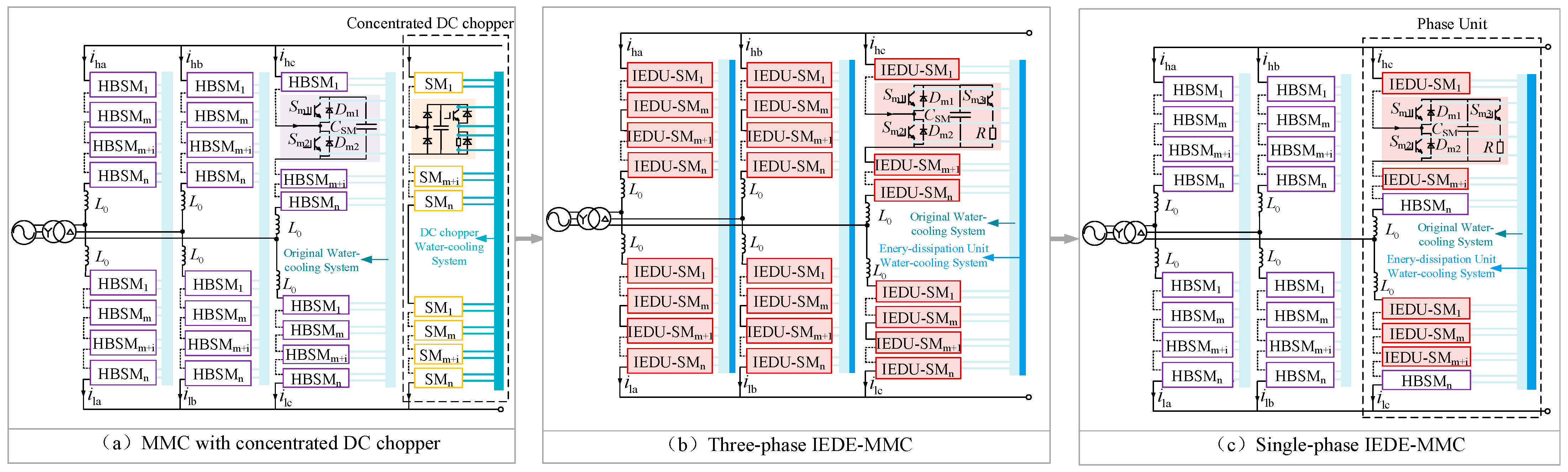
As shown in Figure 2a, a conventional concentrated DC chopper is placed outside the MMC, and the energy dissipation resistors are installed in the chopper branches to dissipate surplus power. This scheme involves a large number of devices, leading to a relatively high cost. Since the SM of the MMC is structurally similar to that of a distributed DC chopper, the two can be combined to form the IEDE-MMC. By integrating energy dissipation units into the MMC, conventional SMs are transformed into IEDU-SMs with active power dissipation capability, enabling the MMC to achieve surplus power FRT. Figure 2b shows the conventional IEDE-MMC, in which IEDU-SMs are evenly distributed across the three-phase bridge arms. However, when this configuration is applied in practical projects, the arrangement of power devices and water-cooling systems in all three phase arms must be modified. For each phase, the water-cooling system must be expanded to accommodate the energy dissipation units, resulting in a larger converter size and complex engineering issues related to on-site construction and equipment operation and maintenance.
Figure 2.
Comparison of three surplus power FRT schemes.
Therefore, to ensure FRT capability, this paper proposes a single-phase optimal configuration of the IEDE-MMC, in which the energy dissipation units are added to only one phase unit SM, and the remaining two-phase unit SMs are HBSMs. The topology is shown in Figure 2c. The more centralized arrangement of the dissipation units simplifies the water connections to the heat sinks and reduces electrical connection costs. Only one phase unit needs to be retrofitted without changing the relative position of the other two phases, making the system easy to install.
2.2. Control Strategy of Single-Phase IEDE-MMC
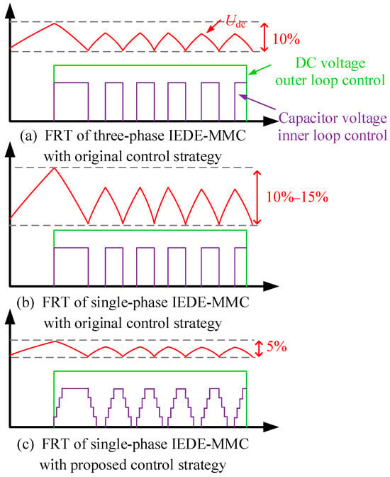
For single-phase IEDE-MMC, the energy dissipation units are more centrally arranged in the single-phase unit. If the original double-loop control strategy for DC voltage and capacitor voltage is adopted when the voltage increases, the number of series-connected power devices involved in switching increases, and the turn-off transient processes of these devices may become inconsistent. As a result, larger DC voltage fluctuations occur when the energy dissipation units are switched in and out.
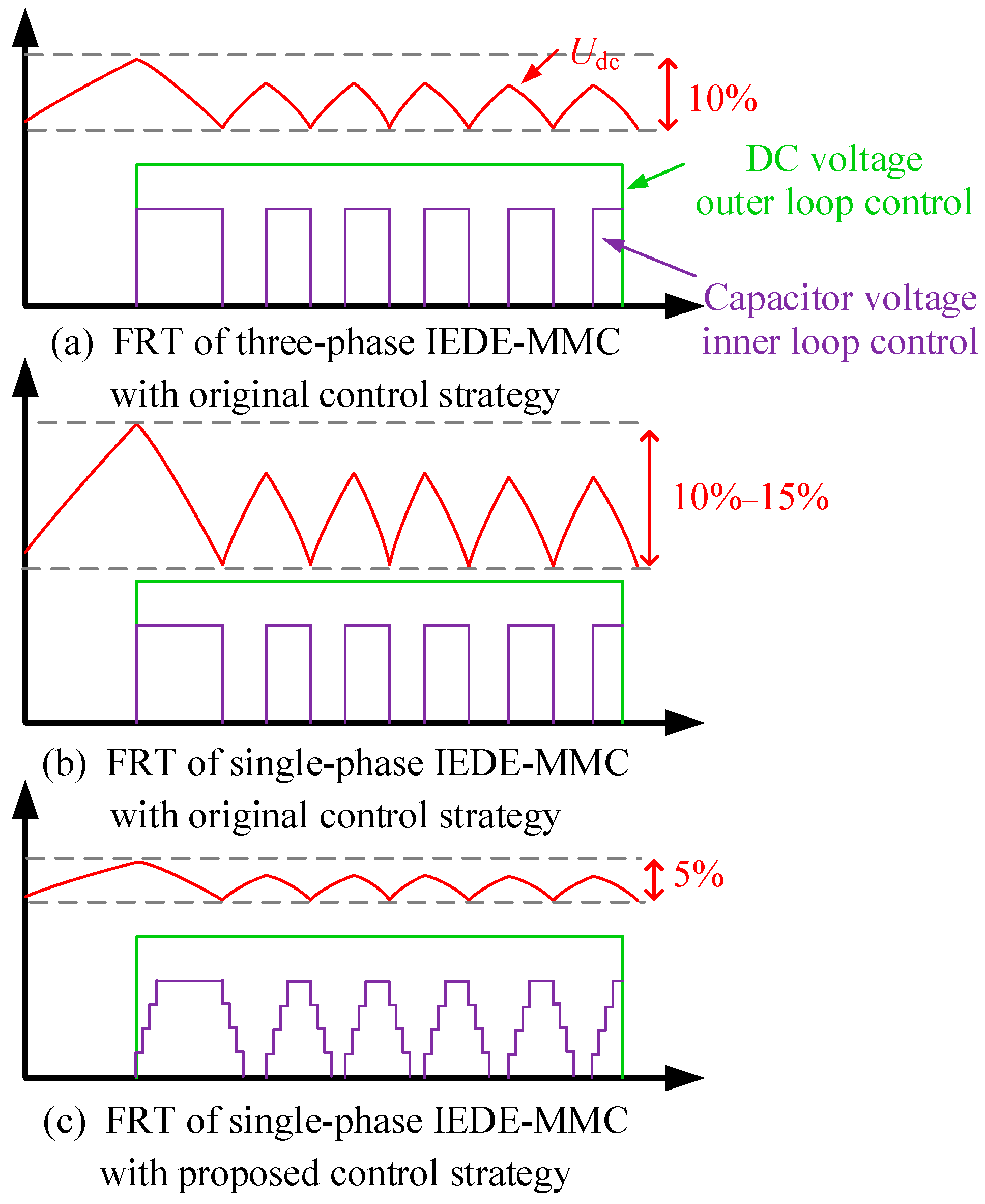
Figure 3 shows the FRT of IEDE-MMC with different control strategies. As shown in Figure 3a, in the three-phase IEDE-MMC adopting the original control strategy, the energy dissipation units are evenly distributed, and the power impact is relatively dispersed; therefore, the DC voltage fluctuation is only approximately 10%. In contrast, in Figure 3b, in the single-phase IEDE-MMC adopting the original control strategy, the energy dissipation units are concentrated in the same phase, producing a step-change in power during switching and resulting in a voltage fluctuation of 10–15%, which affects system stability. To address this issue, this paper proposes a DC voltage hysteresis and stepwise switching control strategy, as shown in Figure 3c. By limiting the upper and lower voltage boundaries through hysteresis control and decomposing the abrupt power change into multiple small steps through stepwise switching, the voltage fluctuation is suppressed to approximately 5%.
Figure 3.
FRT of IEDE-MMC with different control strategy.
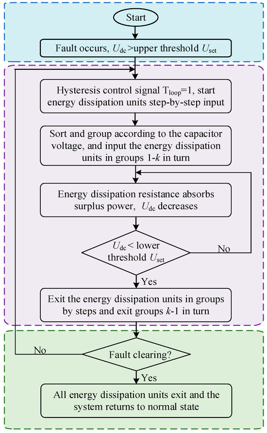
This paper proposes a soft control strategy for energy dissipation units based on hysteresis loop control and stepwise switching, and its flow chart is shown in Figure 4. In this strategy, the hysteresis control is responsible for the macroscopic DC voltage range constraint, while the stepwise switching is responsible for the microscopic engagement speed and capacitor voltage balancing.
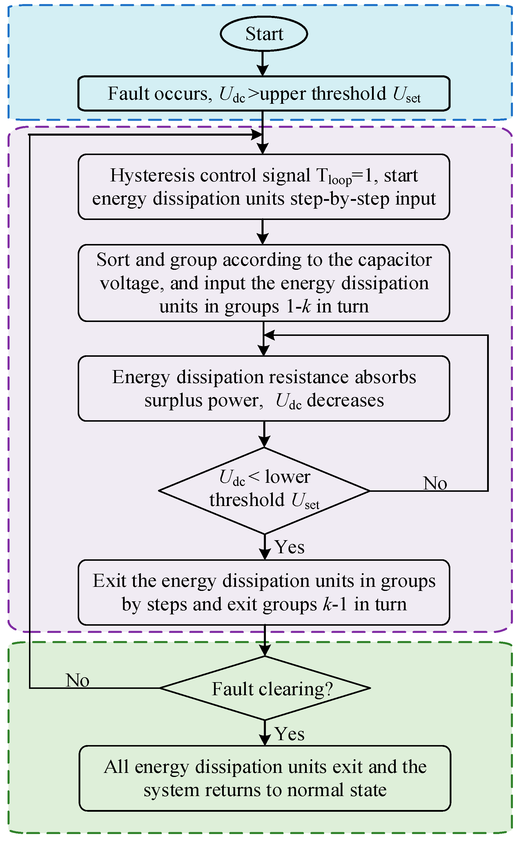
Figure 4.
Flow chart of control strategy proposed by single-phase IEDE-MMC.
The IEDE-MMC incorporates independent energy dissipation unit control logic into the original MMC control. Moreover, the energy dissipation control does not influence the operation and transmission capacity of the MMC itself. The outer loop adopts DC voltage hysteresis control, which is used as the enabling signal of the energy dissipation unit. The hysteresis thresholds are selected according to the allowable DC overvoltage range and the allowable lower voltage limit of the submodule capacitors. The upper threshold Umax must be lower than the DC overvoltage protection level, so that FRT control is activated before protection is triggered. The lower threshold Umin prevents excessive energy dissipation from reducing both the DC voltage and the IEDU-SM capacitor voltages too much.
Owing to the arm reactors employed in the single-phase IEDE-MMC, the simultaneous switching of a large number of IEDU-SMs produces an effect comparable to that of engaging a lumped energy dissipation resistor. This results in significant voltage and current transients (du/dt and di/dt) on the DC side, and the severity of this phenomenon increases with the number of SMs. Stepwise switching is an effective strategy to address this issue. By engaging or disengaging one group of energy dissipation units at each step, the DC voltage rises or falls in a stepwise manner, leading to smoother voltage fluctuations. The sequence of engagement and disengagement is designed to balance the surplus power dissipated among the resistors. On one hand, this ensures that the power absorbed by each energy dissipation resistor is relatively balanced, preventing some energy dissipation resistors from experiencing serious overheating due to prolonged continuous operation. On the other hand, it balances the thermal load on the SM water-cooling system, which helps prolong its service life.
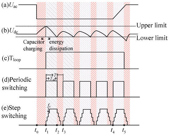
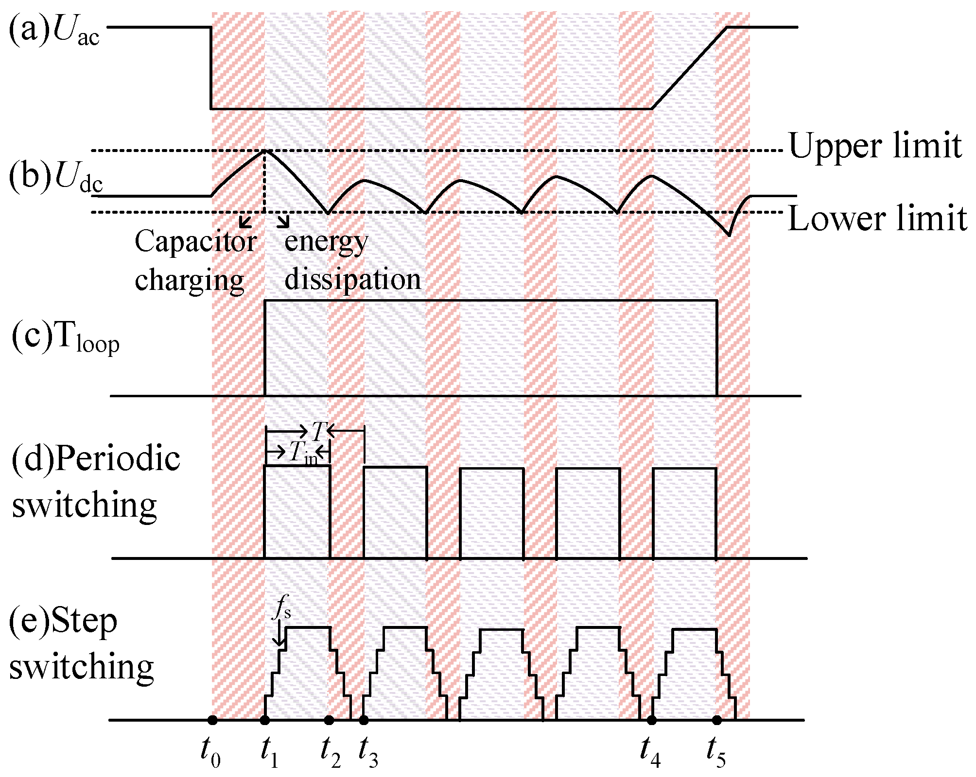
Figure 5 shows the waveforms of single-phase IEDE-MMC during the FRT. Figure 5a–d show the waveforms of the following quantities during a grid-side AC main network fault, respectively: the grid-side AC fault voltage Uac, the DC voltage Udc, the DC voltage hysteresis output Tloop and the periodic switching signal of the energy dissipation units.
Figure 5.
Surplus power FRT of single-phase IEDE-MMC action waveform.
Before t0, the system operates normally. The energy dissipation units remain in standby mode, and the single-phase IEDE-MMC serves only for active power transmission. When a grid fault occurs at t0, fault phase voltage drops rapidly, the wind-farm-side MMC is limited in its power delivery capability, while the input power Pin of the system remains unchanged. This generates surplus power ΔP, which charges the equivalent capacitance Ceq of the DC submarine cable and the MMC, causing Udc to rise. At t1, Udc rises to the upper limit, Tloop transitions from 0 to 1, the energy dissipation units are engaged, the resistors absorb the surplus power, and then Udc decreases. At t2, Udc reaches the hysteresis lower limit, and the energy dissipation units are disengaged. The surplus power recharges the SM capacitor and Udc rises until the completion of a switching cycle at t4. Thereafter, the above process repeats, and the DC voltage exhibits a sawtooth waveform. The fault starts to clear at t5, Udc drops to the shutdown voltage at t6, Tloop turns from 1 to 0, and the energy dissipation function of the single-phase IEDE-MMC turns off. Thereafter, the MMC will experience power overshoot due to instantaneous grid-connected power recovery, and Udc will return to its rated value after regulation.
3. Design Method of the Single-Phase IEDE-MMC
3.1. Number of IEDU-SM Configurations
Table 2 below describes the symbols used in the parameter derivation.
Table 2.
Variables and definitions.
According to the short-term constancy assumption of surplus power, the system surplus power is approximately constant within tens to hundreds of milliseconds after the AC power grid failure at the receiving end. Under this time scale, the surplus power to be absorbed by the energy dissipation units can be expressed as xPrated, where Prated is the rated transmission power of the system, and x is a constant between 0 and 1. To maintain the SM capacitor voltage near its rated value, the number of energy dissipation units that need to be engaged in each bridge arm, denoted as num can be expressed as Equation (1). It is worth noting that at the parameter design stage, according to the assumption of dissipative resistance power approximation and current waveform linearization, Uc,i ≈ USM is assumed to calculate the rated capacity of a single dissipative unit.
where function round () is a rounding function, p is the number of phase units with energy dissipation units installed, USM is the rated voltage of SM capacitor, and R is the energy dissipation resistance value of a single energy dissipation unit.
In extreme case of a three-phase grounding short-circuit fault on the AC grid side, the grid-side MMC station loses all power transmission capacity, and the energy dissipated by the energy dissipation units reaches its maximum value [19]. During the fault period, the power transmitted by the wind-farm-side MMC is balanced with the power consumed by energy dissipation resistors, x is taken as 1 in Equation (1), and the obtained value of num is defined as the required number of IEDU-SMs in a single bridge arm, denoted as m.
Compared to the three-phase symmetric configuration, p is reduced to 1/3 in the single-phase configuration scheme. The SM capacitor voltage can be equalized by increasing the number of IEDU-SMs on a single bridge arm m or by reducing the value of the resistor R. As m increases, the device cost increases. If R decreases, the power absorbed on a single resistor increases and the cost of heat dissipation increases. Meanwhile, the current flowing through the switching devices increases and the Insulated Gate Bipolar Transistor (IGBT) cost increases. Therefore, selecting an appropriate configuration scheme can ensure the FRT performance, minimize the investment cost, and keep the current flowing through the switching devices in the energy dissipation unit within the allowable range [20].
The investment cost of IEDE-MMC consists of two parts: the cost of devices in the energy dissipation units and the cost of heat dissipation. Let W be a composite index of the investment cost, which can be expressed as
where α1 and α2 are the weight coefficients of each parameter. The corresponding values can be selected according to the actual situation; in this paper, to simplify the calculation, both are taken as 1. Wheat and Wdevice represent the heat dissipation cost and device cost of a single energy dissipation unit, respectively.
In addition to the cost factor, it is also necessary to limit the current flowing through the switching devices in the energy dissipation unit, denoted as IIGBT, which is affected by the turn-off current of selected switching device I1 and bridge arm blocking current I2.
Based on Equations (3) and (4), the required number of IEDU-SMs m is obtained. The resistance value R can then be calculated using Equation (2).
3.2. Control Frequency
When Tloop is active, the energy dissipation units are engaged following a specific periodic pattern. During the engagement phase, the resistors dissipate the surplus power, thereby reducing the DC voltage. Assume that the DC voltage drops to the lower limit Umin just before the energy dissipation units exit, that the engagement duration of energy dissipation units is Tin, and that the switching period is T. Accordingly, the energy relationship governing the system during FRT is given by Equation (5).
where PR is the power dissipated by each resistor.
Based on the linear equivalent capacitance assumption, the parasitic capacitance of the DC cable and the MMC submodule capacitances are combined into an equivalent linear lumped capacitance Ceq, neglecting parameter variations during FRT. Based on this, during the disengagement phase of the energy dissipation units, the output power of the wind farm charges the equivalent capacitance of the system. Assuming that the DC voltage rises to the upper limit Umax just before the energy dissipation units are engaged, and that the disengagement duration is Tout = T − Tin, the energy relationship during this phase can be expressed as Equation (6).
From Equations (5) and (6), the appropriate switching frequency f and duty cycle D of the energy dissipation units can be derived, as shown in Equations (7) and (8), respectively.
The capacitor voltage can reflect, to some extent, the amount of power dissipated by the corresponding resistor. A higher capacitor voltage indicates that less power is currently being dissipated and that the corresponding unit should be prioritized for engagement. When the energy dissipation function is activated, the IEDU-SMs are sorted according to their capacitor voltages and then divided into k groups. The first group is set to have the highest average capacitor voltage, while the k-th group has the lowest average capacitor voltage. Subsequently, at a time interval of Δt, the energy dissipation units are engaged stepwise in the order of groups 1, 2, …, k. As each group is engaged, the total dissipated power increases by one step. Once all k groups are engaged, the dissipation capacity reaches its maximum, and the DC voltage continues to decrease. Similarly, during the stepwise removal process, groups k, k − 1, …, 1 exit sequentially after Δt. This switching strategy, based on sorting and grouping according to SM capacitor voltages, prioritizes the activation of energy dissipation units connected in parallel with SMs having higher capacitor voltages, allowing them to dissipate energy over a longer period and thereby reducing their capacitor voltages more effectively. The dynamic grouping method based on capacitor voltage sorting allows each unit to take turns undertaking the dissipation task, thereby avoiding localized overheating. The grouped stepwise switching prevents all resistors from simultaneously bearing the maximum thermal shock, thereby improving thermal management stability.
The capacitance of the SMs serve as the basis for determining the stepwise switching frequency fs. As illustrated in Figure 5e, engagement begins at t1 with the group having the highest average capacitor voltage, and the corresponding SM capacitors continue to discharge until t3. During the period from t2 to t3, all energy dissipation units are engaged, and the system reaches a steady-state balance between the dissipated power and the surplus power. Therefore, precise control of the stepwise switching frequency is required to discharge the SM capacitors to the preset lower voltage limit at t2.
When xPrated is dissipated, the average capacitor voltage of the k-th group of energy dissipation units is lowest during the period from t1 to t2, having been continuously charged over k − 1 step intervals. With the discharge current approximated as linearly rising, the charging current is half of the rated current, IIEDU. This yields the stepwise switching interval Δt as given in Equation (9).
4. Simulation and Experimental Verification
4.1. Simulation System Parameters
The offshore wind farm MMC-HVDC transmission system shown in Figure 1 is built on the PSCAD/EMTDC simulation platform to verify the rationality of the proposed single-phase optimal configuration of the IEDE-MMC topology and control strategy in this paper. The conventional half-bridge MMC is used for the wind-farm-side MMC with V/F control, and the single-phase IEDE-MMC topology with Vdc/Q control is used for the grid-side MMC station. No additional energy dissipation devices are installed.
The configuration ratio of IEDU-SM to HBSM is calculated according to Equations (3) and (4). A 4.5 kV/1 kA IGBT module is used as the switching device, which allows a higher current to flow through the energy dissipation unit compared with the 4.5 kV/0.65 kA IGBT module selected in [20]. The cost of the two models of IGBT is similar, but the configuration quantity of IEDU-SM can be further reduced to one-third. The main system circuit parameters are listed in Table 3.
Table 3.
Main circuit parameters.
4.2. Simulation Results
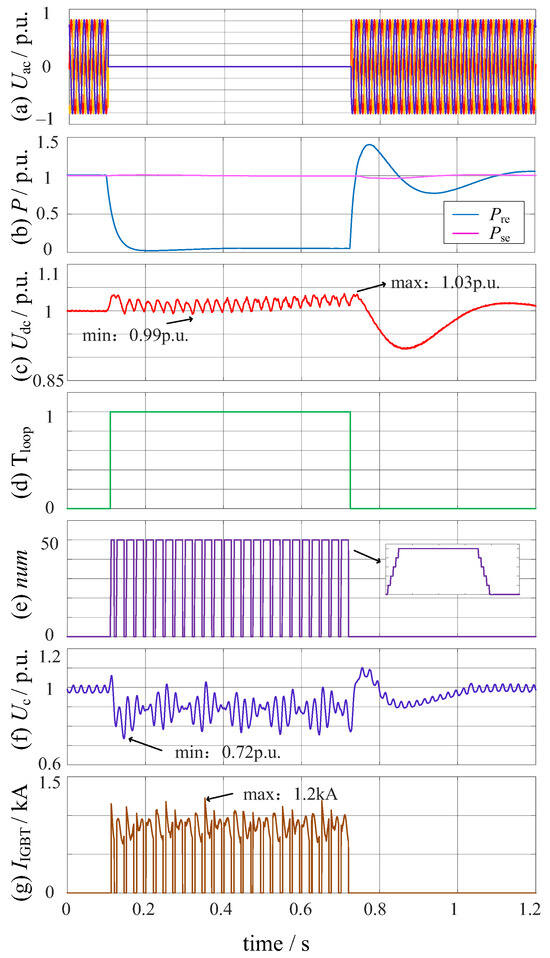
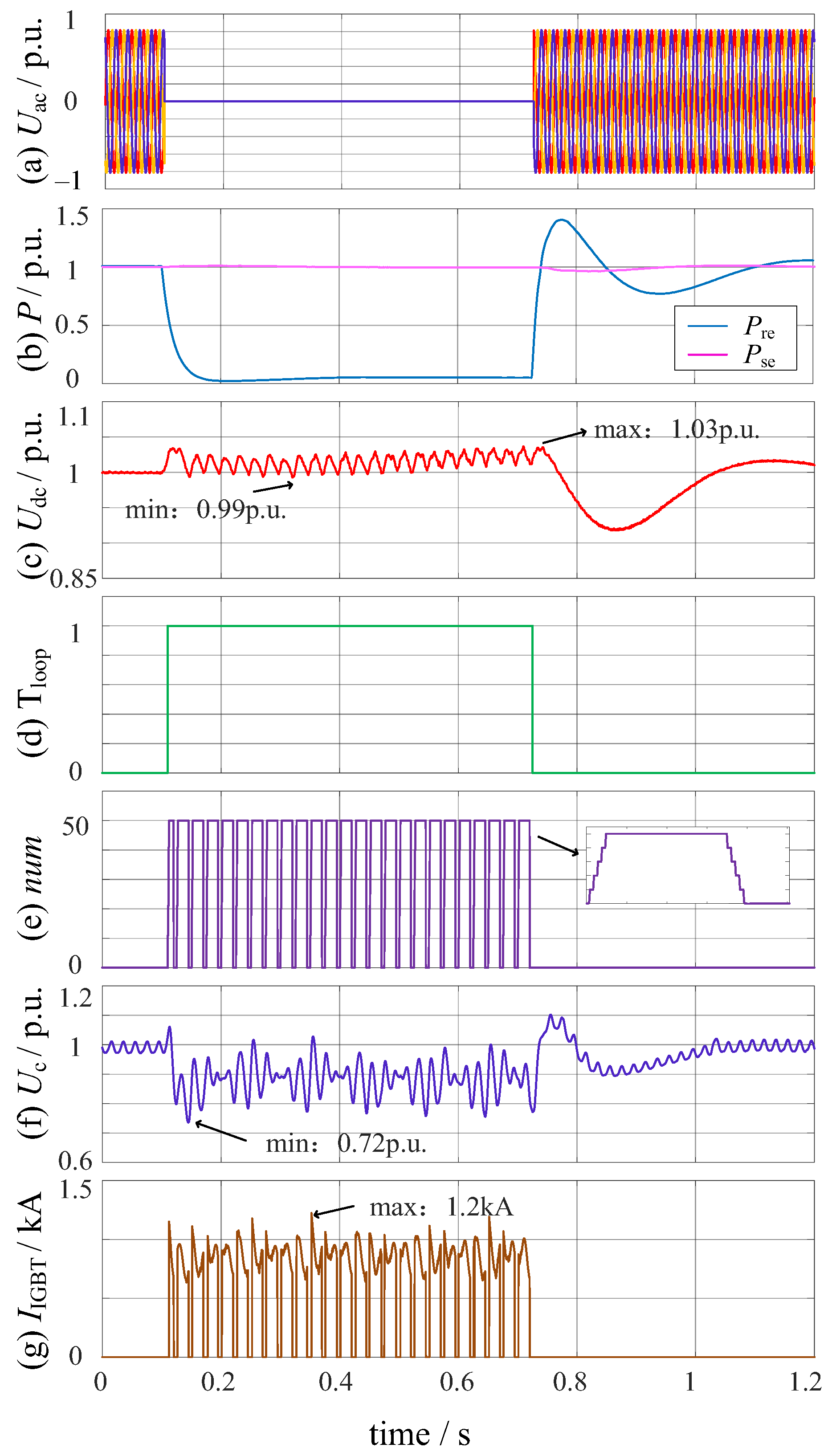
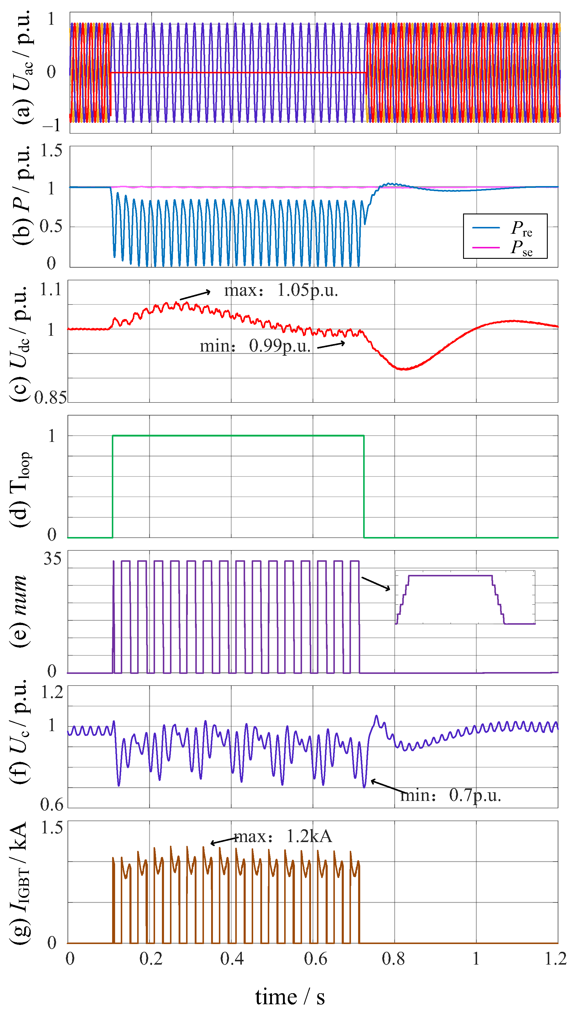
A three-phase short-circuit fault is applied at the grid-side AC transformer at 0.1 s and lasts for 0.625 s before clearing. Figure 6 shows the simulated waveforms of the system with the fault. Figure 6a,b show that at t = 0.1 s, the grid-side voltage drops to zero; the active power received by the wind-farm-side MMC from the offshore wind farm remains unchanged, while the grid-side MMC station completely loses the power transmission capacity, resulting in surplus power. From Figure 6c,d, surplus power charges the capacitor, causing the DC voltage to rise, and when the voltage limit is reached, Tloop is activated. During energy dissipation, the surplus power generated by the system is balanced by the power dissipated by the resistor, and the DC voltage reaches up to 1.03 p.u. and down to 0.99 p.u. The fault is cleared at 0.725 s, and the IEDU-SMs are disengaged group by group. The simulation results show that the single-phase IEDE-MMC with the control strategy proposed in this paper can limit the DC voltage fluctuation to within 4% and avoid an overall DC system overvoltage.
Figure 6.
Simulation waveforms of three–phase short–circuit fault.
Figure 6e shows the engaged number of energy dissipation units. The energy dissipation units installed on each bridge arm are all engaged during the three-phase short circuit, which corresponds to the calculation result of Equation (1), and the energy dissipation units are switched stepwise according to the duty cycle and frequency calculated by Equations (7)–(9). From Figure 6f,g, the capacitor voltage of the IEDU-SM decreases slightly throughout the FRT period, but does not fall below 0.72 p.u. The maximum current flowing through the switching devices in the energy dissipation unit is 1.2 kA, which ensures safe operation of the switching devices.
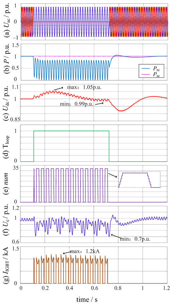
For an asymmetrical short-circuit fault in the AC system at the receiving end, the simulation waveforms taking the two-phase grounding short-circuit fault as an example are shown in Figure 7. As shown in Figure 7a, a two-phase grounding short-circuit fault occurs at the grid-side AC transformer at t = 0.1 s and is cleared after 0.625 s. Figure 7b shows that the grid-side MMC still retains a certain power transmission capacity during a two-phase grounding fault. As shown in Figure 7c, the DC voltage does not exceed 1.05 p.u. nor does it fall below 0.99 p.u., which is within the permissible fluctuation range. The DC voltage fluctuation increases slightly compared to the previous operating condition.
Figure 7.
Simulation waveforms of two-phase grounding short-circuit fault.
Figure 7e shows the number of engaged energy dissipation units under this fault condition. According to Equation (1), only 32 energy dissipation units are needed to meet the FRT requirement. Figure 7f,g show the SM capacitor voltage and the current flowing through the switching devices in energy dissipation units, respectively. The capacitor voltage of the IEDU-SM drops slightly during the fault, reaching a minimum of 0.7 p.u. The current flowing through the switching devices in the energy dissipation units reaches 1.2 kA, within the range allowed by the selected switching device.
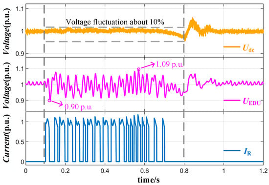
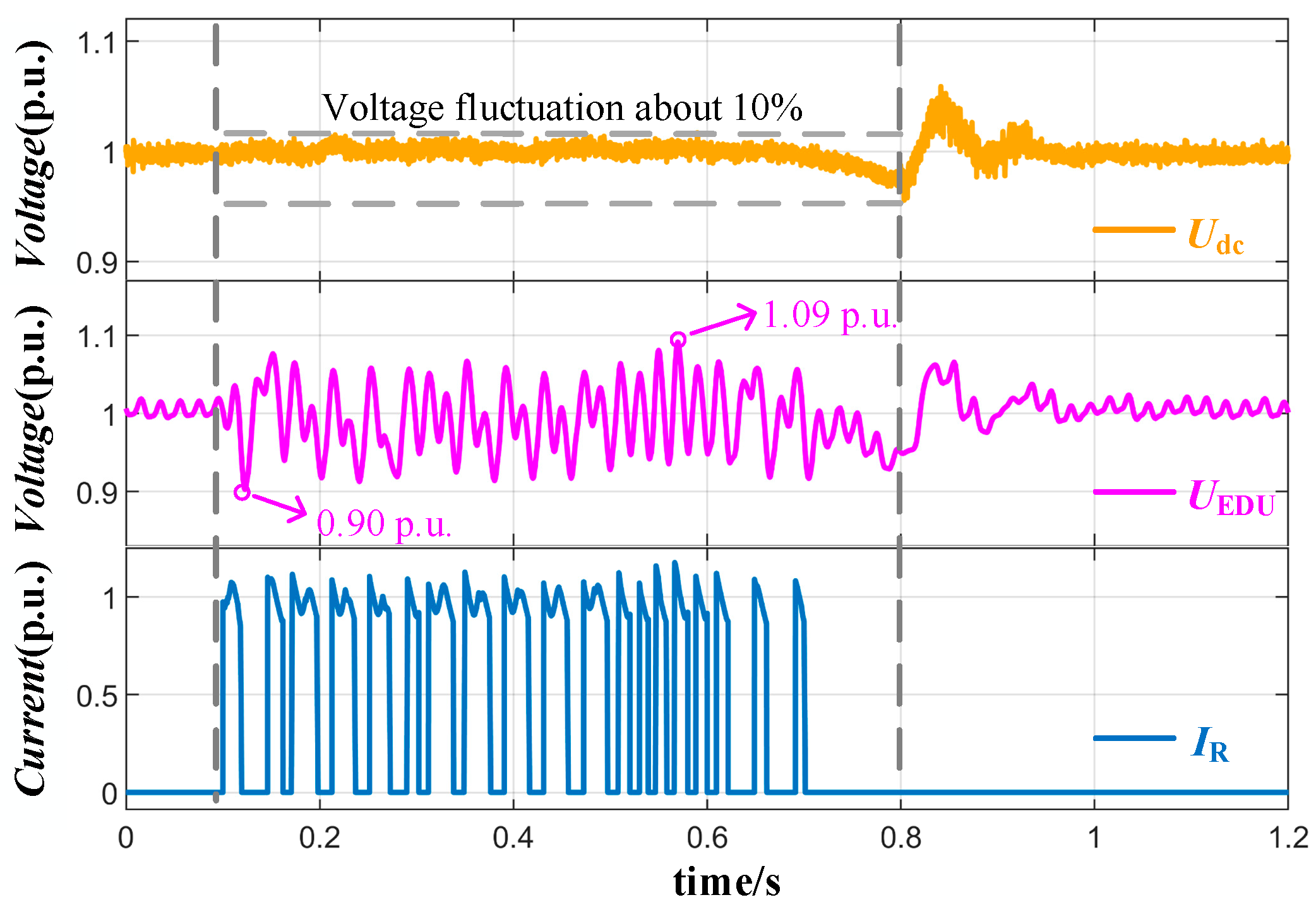
On this basis, the performance of the proposed scheme is further compared with that of the concentrated DCC and the three-phase IEDE-MMC, and the responses under three-phase short-circuit and two-phase-to-ground short-circuit faults are analyzed. The three-phase short-circuit is the most severe operating condition, where the grid-side MMC almost completely loses its active power transmission capability. Compared with the concentrated DCC, the single-phase IEDE-MMC integrates the dissipation units into the submodules, eliminating the need for an independent DC dissipation device and avoiding the issues faced by the DCC, such as high DC voltage stress, concentrated heat dissipation, and installation space requirements. Compared with the three-phase IEDE-MMC, the single-phase structure requires retrofitting only one phase unit, resulting in less engineering modification. However, this advantage comes with a significant cost: because that phase must independently undertake a greater dissipation task, its low-frequency arm current pulsations become more pronounced, and the capacitor voltage drop increases accordingly. Moreover, the asymmetric inter-phase energy distribution further induces internal circulating current issues. In contrast, in the three-phase IEDE-MMC, the DC voltage fluctuation is effectively controlled within 10%, and the submodule capacitor voltage fluctuates only within the range of 0.90 p.u. to 1.09 p.u., as shown in Figure 8, exhibiting more balanced overall operational characteristics.
Figure 8.
Simulation waveforms of three-phase short-circuit fault in the three-phase IEDE-MMC.
Under the two-phase-to-ground short-circuit fault, the receiving-end MMC still retains part of its active power transmission capability, and the surplus power is lower. The proposed strategy adaptively reduces the number of engaged dissipation units to avoid excessive dissipation. For asymmetrical faults, the concentrated DCC operates only based on the DC voltage and cannot mitigate the arm energy imbalance caused by AC-side asymmetry; the three-phase IEDE-MMC, with its uniformly distributed dissipation units, achieves more balanced energy sharing, whereas the single-phase IEDE-MMC relies more heavily on capacitor voltage sorting and grouped stepwise switching to suppress arm voltage deviation, capacitor voltage drop, negative-sequence-related circulating current, and concentrated thermal load.
4.3. Experimental Methods and Analysis
Based on the analysis of system simulation characteristics, a towing test platform is further constructed to carry out equivalent experimental research on the IEDE-MMC.
The experimental platform includes voltage differential probes, a digital signal processor (DSP) power supply, an isolation transformer, Rogowski coils, an experimental platform control board, and a high-potential measurement system. The voltage differential probe is used to measure the voltage across the device under test, with a sampling rate of 10 MHz; the Rogowski coil is used to measure the arm current, with a sampling rate ranging from 10 MHz to 100 MHz. The DSP power supply is used for pre-charging and for compensating power losses during operation. The isolation transformer supplies the driver board, and the control board generates the clock and sinusoidal pulse-width modulation (SPWM) signals. The high-potential acquisition unit converts the voltage and current probe signals into optical signals and transmits them to the receiver, where they are converted back into electrical signals for display.
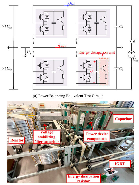
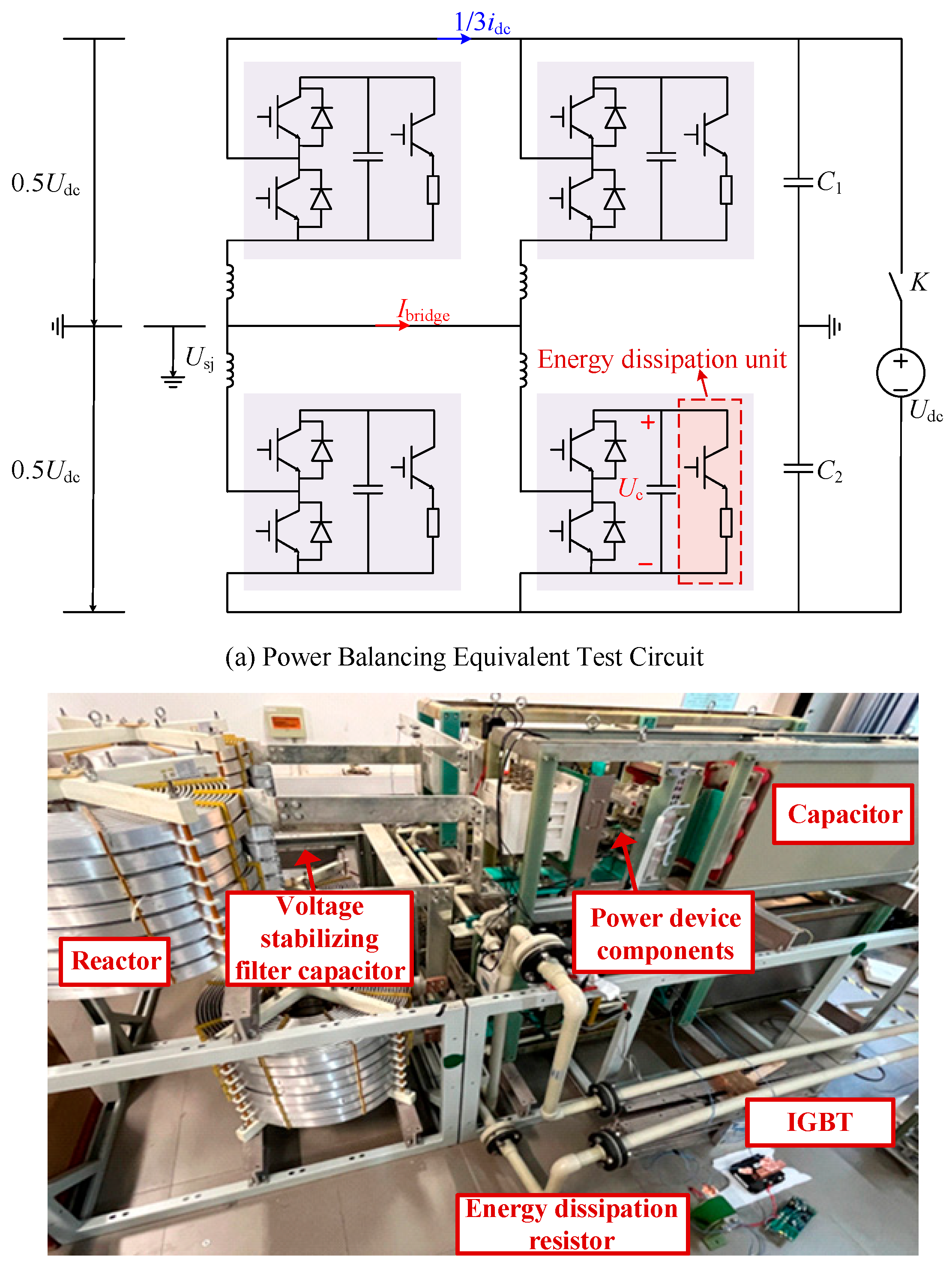
Based on the measurement equipment described above, the main measurement points of the experiment include the submodule capacitor voltage and the arm current. These measurement points correspond to the key variables required to verify the equivalent FRT process, as shown in Figure 9a.
Figure 9.
Equivalent test circuit.
Figure 9 illustrates the equivalent test circuit. This circuit utilizes the power hedging equivalent test principle to achieve bidirectional power exchange, and simulates the generation of surplus power by adjusting the DC voltage source. An energy dissipation unit is connected in parallel with the submodule, thereby introducing FRT capability and enabling the equivalent simulation of the FRT process. In the figure, K is the charging switch, Udc is the DC charging power supply, C1 and C2 are voltage stabilizing filter capacitors, and the AC-side output voltage of phase j of the MMC valve is denoted by Usj (j = a, b, c).
To more accurately emulate the behavior of the converter valve under FRT conditions, the FRT equivalent test method based on the IEDE-MMC equivalent test circuit is proposed. The specific steps are as follows: Once the converter valve enters normal operation, the DC voltage source output is increased to charge the SM capacitors, thereby emulating a rising DC voltage condition. When the capacitor voltage reaches a preset threshold, the control strategy regulates the turn-on and turn-off of the energy dissipation switch to achieve engagement and disengagement of the energy dissipation unit.
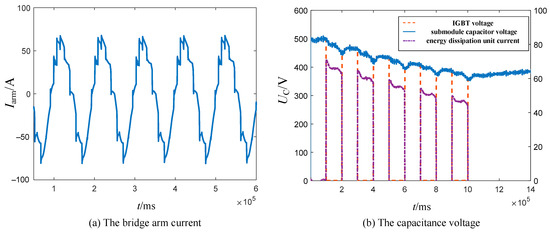
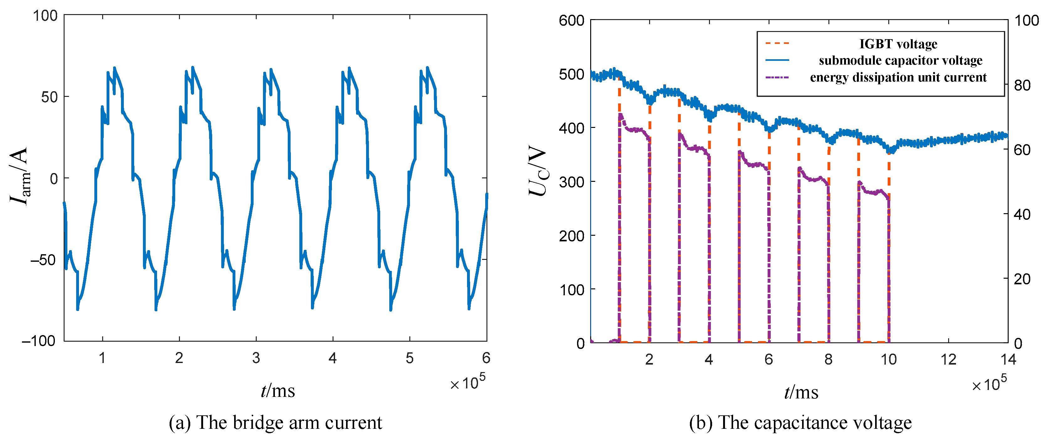
When the converter valve is in the steady-state operation stage, the exchanged power is controlled by adjusting the phase angle. The arm current waveform is shown in Figure 10a, which demonstrates good current waveform quality. When the capacitor voltage rises to 500 V, the energy dissipation unit is controlled to periodically engage and disengage to absorb the surplus power, as illustrated in Figure 10b. As shown in the figure, during the engagement period of the energy dissipation unit, the IGBT operates five times in total, dissipating a cumulative energy of 3.075 MJ. The above experimental results demonstrate that the equivalent test circuit is capable of absorbing surplus power.
Figure 10.
The experimental waveform.
Furthermore, a quantitative comparison between the experimental and simulation results is presented: in the equivalent experiment, the capacitor voltage drops by 50 V each time the dissipation unit is engaged, with a dissipated energy of 615 kJ; in the simulation, the voltage drops by 360 V each time, with a dissipated energy of 4430 kJ. Over the same time interval, both the voltage drop amplitude and the dissipated energy in the experiment are approximately 1/7.2 of those in the simulation, which is consistent with the theoretical value, thereby verifying the effectiveness of the equivalent experimental method.
5. Technical Economy Analysis
In order to verify the superiority of the proposed single-phase optimal configuration of the IEDE-MMC over the three-phase uniform configuration in terms of cost and control strategy, a technical economy analysis of the different schemes is conducted using the above simulation model and parameters.
5.1. Cost Analysis
The IEDE-MMC investment cost includes the inherent cost of the conventional MMC as well as the additional cost resulting from the installation of energy dissipation units. The investment cost of energy dissipation depends on the rated withstand voltage level and device usage of various power switching devices in the SM. In this paper, it is assumed that all power devices in each topology share the same voltage rating; that is, the IGBT modules, diodes, and resistors are selected with the same voltage rating. The device selection for the single-phase configuration IEDE-MMC scheme is shown in Table 3. The IGBT module for the three-phase configuration IEDE-MMC is a 4.5 kV/0.65 kA IGBT module with a resistance of 3 Ω. The same type of diode is selected for both configuration schemes. When the capacitor voltage is relatively constant, the resistance value is inversely proportional to the power consumed by the resistor. Therefore, for the single-phase configuration of IEDE-SM, a lower resistance value is adopted, implying that the water-cooling system needs to be further expanded. Based on the cost of a single 4.5 kV/0.65 kA IGBT module, the required equipment type, equipment cost, and the number of retrofitted IEDE-SMs for the two configuration options are shown in column (a), (b) and (c) in Table 4, respectively. The cost required for each type of equipment and the total cost of retrofitting energy dissipation units after considering the quantities are given in column (d), (e) in Table 4, respectively. As shown in column (e), the use of the scheme proposed in this paper offers a 33% cost reduction compared to the three-phase configuration scheme, demonstrating a significant cost advantage.
Table 4.
Equipment paraments and cost comparison.
5.2. Control Strategy Analysis
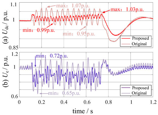
The superiority of the control strategy proposed in this paper is demonstrated by using the three-phase short-circuit fault as an example. Figure 11 presents the voltage waveforms under the original versus the proposed control strategy. Under the original control strategy, the switching of the single-phase IEDE-MMC based on voltage thresholds tends to cause multiple units to be engaged almost simultaneously, leading to a sudden surge in dissipation power. As a result, the DC voltage fluctuation reaches 12%, and the minimum capacitor voltage drops to 0.65 p.u. In contrast, the proposed strategy introduces DC voltage hysteresis control and grouped stepwise switching based on capacitor voltage sorting, which decompose the high-power dissipation into several small steps. Consequently, the DC voltage fluctuation is reduced to 4%, corresponding to a reduction of 66.7%, while the minimum capacitor voltage is increased to 0.72 p.u., representing an increase of 10.8%. Meanwhile, the proposed strategy reduces the risk of overvoltage protection misoperation, mitigates capacitor voltage stress and IGBT thermal shock, improves bridge arm voltage balancing, and suppresses circulating current disturbances.
Figure 11.
Comparison of control strategy applied to single-phase IEDE-MMC.
6. Conclusions
To address the surplus power FRT issue in offshore wind power VSC-HVDC transmission systems, this paper proposes a single-phase IEDE-MMC scheme. Compared with the conventional three-phase IEDE-MMC, the proposed scheme installs IEDU-SMs in only one phase unit, while the other two phases are left unchanged. This reduces the number of submodules requiring retrofitting and simplifies installation, cooling arrangement, maintenance, and engineering implementation.
To suppress DC bus voltage fluctuations caused by the concentrated single-phase energy dissipation units, this paper develops a control strategy that combines DC bus voltage hysteresis control with capacitor-voltage-based grouped stepwise switching. The hysteresis control determines the enabling and disabling of the energy dissipation function, while the grouped stepwise switching strategy determines the engagement and disengagement sequence of the IEDU-SMs. By prioritizing submodules with higher capacitor voltages for engagement, the proposed strategy improves submodule capacitor voltage balancing and mitigates the voltage impact caused by simultaneous switching.
Simulation results under three-phase short-circuit and two-phase short-circuit faults verify the effectiveness of the proposed topology and control strategy. Under severe three-phase short-circuit faults, the DC bus voltage is limited within the range of approximately 0.99 p.u. to 1.03 p.u., and the capacitor voltages of the IEDU-SMs are maintained above 0.72 p.u. Experimental results further validate the feasibility of the proposed energy dissipation method. The technical economy analysis demonstrates that, compared with the three-phase IEDE-MMC, the proposed single-phase IEDE-MMC can reduce the investment cost by approximately 33%. In the single-phase IEDE-MMC, compared with the original control strategy, the proposed control strategy reduces the DC bus voltage ripple by approximately 66.7% and raises the lower limit of the submodule capacitor voltage by approximately 10.8%.
It should be noted that the single-phase configuration concentrates the energy dissipation task and thermal load in one phase unit. Therefore, in practical applications, the local heat dissipation capacity, thermal distribution, and circulating current suppression should be carefully evaluated. Future work will focus on long-duration thermal testing and the coordinated control between the energy dissipation strategy and MMC circulating current suppression.
Author Contributions
Conceptualization, Y.L. and W.J.; methodology, Y.L.; software, W.J.; validation, Y.L., D.S. and Q.C.; formal analysis, P.Q.; investigation, Q.C.; resources, F.X.; data curation, X.N.; writing—original draft preparation, W.J.; writing—review and editing, D.S. and F.X.; visualization, S.W.; supervision, S.W.; project administration, Y.L.; funding acquisition, Y.L. All authors have read and agreed to the published version of the manuscript.
Funding
This work was supported by State Grid Zhejiang Electric Power Co., Ltd., under Grant No. 5211DS250007.
Data Availability Statement
The data presented in this study are available on request from the corresponding author.
Conflicts of Interest
Authors Yi Lu, Qian Chen, Peng Qiu, Feng Xu, and Xiaojun Ni were employed by the company State Grid Zhejiang Electric Power Research Institute. The remaining authors declare that the research was conducted in the absence of any commercial or financial relationships that could be construed as a potential conflict of interest. The authors declare that this study received funding from State Grid Zhejiang Electric Power Co., Ltd. The funder was not involved in the study design, collection, analysis, interpretation of data, the writing of this article or the decision to submit it for publication.
Abbreviations
The following abbreviations are used in this manuscript:
| MMC | Modular Multilevel Converter |
| FRT | Fault Ride Through |
| SM | Submodule |
| IEDE-MMC | Integrated Energy Dissipation Equipment of MMC |
| VSC-HVDC | Voltage Source Converter based High Voltage Direct Current |
| ACC | AC chopper |
| DCC | DC chopper |
| IEDU-SM | Integrated Energy Dissipation Unit of SM |
| HBSMs | Half-Bridge submodules |
| MMC-HVDC | Modular Multilevel Converter based High Voltage Direct Current |
| IGBT | Insulated Gate Bipolar Transistor |
| DSP | Digital Signal Processor |
| SPWM | Sinusoidal Pulse Width Modulation |
References
- Jia, G.; Chen, M.; Tang, S.; Zhang, C.; Zhao, B. A Modular Multilevel Converter with Active Power Filter for Submodule Capacitor Voltage Ripples and Power Losses Reduction. IEEE Trans. Power Electron. 2020, 35, 1401–11417. [Google Scholar] [CrossRef] [Scilit]
- Guo, J.; Zou, L.; Zhang, N.; Jia, Y.; Pan, X.; Sun, X. Coordinated Active and Reactive Power Control of VSC-HVDC for Enhancing Static Voltage Stability in AC/DC Systems. Energies 2025, 18, 6127. [Google Scholar] [CrossRef] [Scilit]
- Xu, B.; Gao, C.; Zhang, J.; Yang, J.; Xia, B.; He, Z. A Novel DC Chopper Topology for VSC-Based Offshore Wind Farm Connection. IEEE Trans. Power Electron. 2021, 36, 3017–3027. [Google Scholar] [CrossRef] [Scilit]
- Xing, C.; Liu, M.; Peng, J.; Wang, Y.; Shang, C.; Zheng, Z.; Liao, J.; Gao, S. Frequency Stability Control Strategy for Voltage Source Converter-Based Multi-Terminal DC Transmission System. Energies 2024, 17, 1195. [Google Scholar] [CrossRef] [Scilit]
- Zafari, L.; Liu, Y.; Ukil, A.; Nair, N.-K.C. Aspects, Principles, and a Comprehensive Review of Signal Processing Techniques for Fault Detection Advances in HVDC Systems. Energies 2025, 18, 3106. [Google Scholar] [CrossRef] [Scilit]
- Paulo, M.S.; Almeida, A.d.O.; Almeida, P.M.d.; Barbosa, P.G. Control of an Offshore Wind Farm Considering Grid-Connected and Stand-Alone Operation of a High-Voltage Direct Current Transmission System Based on Multilevel Modular Converters. Energies 2023, 16, 5891. [Google Scholar] [CrossRef] [Scilit]
- Karaagac, U.; Mahseredjian, J.; Cai, L.; Saad, H. Offshore wind farm modeling accuracy and efficiency in MMC-Based multiterminal HVDC connection. IEEE Trans. Power Deliv. 2017, 32, 617–627. [Google Scholar] [CrossRef] [Scilit]
- Silva, B.; Moreira, C.L.; Leite, H.; Peças Lopes, J.A. Control strategies for AC fault ride through in multiterminal HVDC grids. IEEE Trans. Power Deliv. 2014, 29, 395–405. [Google Scholar] [CrossRef] [Scilit]
- Kirakosyan, A.; El Moursi, M.S.; Khadkikar, V. Fault Ride Through and Grid Support Topology for the VSC-HVDC Connected Offshore Wind Farms. IEEE Trans. Power Deliv. 2017, 32, 1592–1604. [Google Scholar] [CrossRef] [Scilit]
- Yin, L.; Chen, Q.; Li, B.; Liu, J.; Li, Z.; Liu, Y. A Novel DC Energy Dissipation Topology with Concentrated Dissipation Resistor and Control Method for Offshore Wind VSC-HVDC System. IEEE Trans. Ind. Appl. 2024, 60, 2880–2890. [Google Scholar] [CrossRef] [Scilit]
- Li, Y.; Liu, H.; Liu, C.; Wei, C.; Jiang, W.; Wang, F.; Wang, Z. Study on AC-side dynamic braking-based fault ride-through control for islanded renewable energy system with grid-connected VSC-HVDC transmission. In Proceedings of the Chinese Automation Congress (CAC), Jinan, China, 20–22 October 2017; pp. 6108–6111. [Google Scholar]
- Nentwig, C.; Haubrock, J.; Renner, R.H.; Van Hertem, D. Application of DC choppers in HVDC grids. In Proceedings of the IEEE International Energy Conference (ENERGYCON), Leuven, Belgium, 4–8 April 2016; pp. 1–5. [Google Scholar]
- Chaudhary, S.K.; Teodorescu, R.; Rodriguez, P.; Kjær, P.C. Chopper controlled resistors in VSC-HVDC transmission for WPP with full-scale converters. In Proceedings of the IEEE PES/IAS Conference on Sustainable Alternative Energy (SAE), Valencia, Spain, 28–30 September 2009; pp. 1–8. [Google Scholar]
- Birkel, A.; Schön, A.; Bakran, M.M. Analysis and semiconductor based comparison of energy diverting converter topologies for HVDC transmission systems. In Proceedings of the IEEE 17th European Conference on Power Electronics and Applications, Geneva, Switzerland, 8–10 September 2015; pp. 1–10. [Google Scholar]
- Xu, C.; Zhang, X.; Yu, Z.; Zhao, B.; Chen, Z.; Zeng, R. A Novel DC Chopper with MOV-Based Modular Solid-State Switch and Concentrated Dissipation Resistor for ±400 kV/1100 MW Offshore Wind VSC-HVDC System. IEEE Trans. Power Electron. 2020, 35, 4483–4488. [Google Scholar] [CrossRef] [Scilit]
- Qi, L.; Wu, S.; Zhang, X.; Zhang, M.; Liu, C.; Wang, H.; Wu, L. A Low-Cost DC Chopper with Coupling Transformer for Offshore Wind VSC-HVdc System. IEEE Trans. Power Electron. 2022, 37, 4979–4984. [Google Scholar] [CrossRef] [Scilit]
- Maneiro, J.; Tennakoon, S.; Barker, C.; Hassan, F. Energy diverting converter topologies for HVDC transmission systems. In Proceedings of the 2013 15th European Conference on Power Electronics and Applications (EPE), Lille, France, 2–6 September 2013; pp. 1–10. [Google Scholar]
- Moawwad, A.; El Moursi, M.S.; Xiao, W. Advanced Fault Ride-Through Management Scheme for VSC-HVDC Connecting Offshore Wind Farms. IEEE Trans. Power Syst. 2016, 31, 4923–4934. [Google Scholar] [CrossRef] [Scilit]
- Zhang, C.; Tang, S.; Jiang, F.; Chen, M. A MMC Topology with AC Short-Circuit Fault Ride-Through Capability and its Control Strategies. In Proceedings of the IECON 2021—47th Annual Conference of the IEEE Industrial Electronics Society, Toronto, ON, Canada, 13–16 October 2021; pp. 1–6. [Google Scholar]
- Wu, S.; Zhang, X.; Jia, W.; Zhu, Y.; Qi, L.; Guo, X.; Pan, X. A Modular Multilevel Converter with Integrated Energy Dissipation Equipment for Offshore Wind VSC-HVDC System. IEEE Trans. Sustain. Energy 2022, 13, 353–362. [Google Scholar] [CrossRef] [Scilit]

Disclaimer/Publisher’s Note: The statements, opinions and data contained in all publications are solely those of the individual author(s) and contributor(s) and not of MDPI and/or the editor(s). MDPI and/or the editor(s) disclaim responsibility for any injury to people or property resulting from any ideas, methods, instructions or products referred to in the content. |
© 2026 by the authors. Licensee MDPI, Basel, Switzerland. This article is an open access article distributed under the terms and conditions of the Creative Commons Attribution (CC BY) license.