


Abstract
Metal hydride (MH) systems offer a compelling route to solid-state hydrogen storage, yet their practical charging rate is fundamentally limited by the low effective thermal conductivity of the hydride bed and the substantial exothermic heat generated during absorption. Addressing this thermal bottleneck without sacrificing hydride volume remains a central challenge in MH reactor design. This study proposes an integrated thermal enhancement strategy in which transverse fins are coupled with a sinusoidal corrugated heat transfer tube, combining the boundary-layer disruption effect of corrugated geometry with the extended heat transfer surface provided by fins. A three-dimensional transient numerical model is developed within a porous-medium framework to compare straight-tube and corrugated-tube reactors equipped with different fin arrangements. The influences of corrugated-tube inlet radius, fin length, and fin inclination angle on hydrogen absorption performance are then systematically evaluated. The results show that positioning transverse fins on the upper side of the wave crests establishes the most direct conductive pathway between the hydride bed and the coolant, while appropriate fin geometry effectively suppresses low-conversion dead zones and improves the spatial uniformity of the reaction field. Compared with the finless sinusoidal corrugated-tube reactor and the conventional transverse-finned straight-tube reactor, the optimized configuration shortens hydrogen storage time by 62.74% and 42.05%, respectively, confirming that the synergistic combination of transverse fins and corrugated-tube geometry constitutes an effective and compact thermal management solution for MH hydrogen storage reactors.
1. Introduction
Hydrogen has emerged as a widely studied clean energy carrier owing to its high gravimetric energy content, zero-carbon combustion products, and natural compatibility with renewable electricity generation [1,2]. Among the various storage technologies, solid-state hydrogen storage via metal hydrides stands out for its high volumetric capacity, relatively low operating pressure, and intrinsically safe characteristics [3,4,5]. Despite these merits, the inherently low thermal conductivity of typical MH powders, combined with the substantial exothermic heat released during hydrogen uptake, gives rise to pronounced temperature heterogeneity within the reactor vessel. Such thermal non-uniformity suppresses reaction kinetics, curtails effective material utilization, and degrades long-term cyclic stability [6]. Consequently, implementing efficient thermal management at the reactor scale is a prerequisite for enhancing the hydrogen absorption/desorption rate and maximizing the practical storage capacity of MH-based systems [7].
Embedding heat transfer structures within the MH bed is a widely adopted strategy to address this challenge. Incorporating heat exchange channels into the bed simultaneously enlarges the effective heat transfer area and shortens the thermal conduction path through the low-conductivity hydride powder, both of which promote temperature homogeneity and accelerate the absorption/desorption kinetics [8]. Straight-tube heat exchanger configurations have been extensively investigated as reference designs due to their geometric simplicity and manufacturing convenience. Tong et al. [9] compared several internal heat transfer layouts under the same reactor volume and reported that a single straight heat transfer tube reduced the hydrogen storage time by 33.9% relative to a reactor without an internal tube. Meng et al. [10] showed that increasing the tube number from 4 to 16 significantly decreased the thermal resistance of the bed and shortened the storage time by 58%. Muthukumar et al. [11] further examined the effect of tube number and found that 20 embedded heat transfer tubes yielded the most favorable heat transfer enhancement, reducing the storage time to 235 s.
Helical-tube configurations represent another widely studied approach for heat transfer augmentation, as their curved geometry promotes secondary flow patterns and Dean vortices within the coolant, resulting in enhanced convective mixing. Tong et al. [9] found that the hydrogen storage time decreased by 58.6%, 68.08%, and 73.22% when a helical tube, a helical tube combined with a central straight tube, and double helical tubes were used, respectively, instead of a straight-tube heat exchanger. Wu et al. [12] developed a helical-coil reactor and demonstrated that, under the same heat transfer area, it exhibited better heat and mass transfer behavior than conventional straight-tube and finned-tube heat exchangers; at 4000 s, most regions of the MH bed reached a reacted fraction above 0.6. Guan et al. [13] designed a spherical reactor equipped with a spindle-shaped helical-tube heat exchanger and achieved a 58.26% reduction in storage time versus the structure without helical tubes.
Despite the considerable improvements in absorption/desorption rate offered by helical geometries, the coolant temperature increases progressively along the extended helical flow path. This monotonic rise generates an axial thermal gradient that translates into spatially non-uniform reaction conversion within the MH bed [14], potentially causing localized mechanical stress and accelerating structural degradation. To reconcile thermal uniformity with rapid reaction kinetics, researchers have proposed a variety of embedded heat exchange channels with engineered geometries. Bai et al. [15] optimized a cylindrical reactor containing six rectangular internal channels, and the optimized configuration reduced the hydrogen storage time to 427.0 s, approximately 60% lower than that of a conventional longitudinal finned-tube reactor. Afzal et al. [16] proposed a hexagonal honeycomb heat exchanger and obtained a 30% improvement in storage performance while maintaining high volumetric utilization. Bi et al. [17] developed an MH reactor with corrugated cooling tubes and optimized its structural parameters using a Monte Carlo algorithm, with the optimized design achieving 1.36 times the storage performance of a conventional straight-tube reactor at 560.0 s.
Extended fin structures represent a complementary heat transfer enhancement strategy, as they project high-conductivity solid conduction paths deep into the MH bed and can be combined with internal tube heat exchangers. Yang et al. [18] modeled a U-shaped tube reactor with fins on the straight sections and found that fin-assisted heat removal significantly accelerated hydrogen absorption; when arc-shaped fins were arranged at the curved section of the U-tube, the storage rate almost doubled. Wang et al. [19] proposed a corrugated finned-tube reactor and optimized the fin height, length, and number. Their optimized structure reduced the time required to reach a storage density of 0.8 wt% by 32% compared with a conventional circular-fin configuration. Krishna et al. [20] redesigned longitudinal fins on heat transfer tubes through topology optimization, and the optimized fins shortened the storage time by 8% and 52% compared with genetic-algorithm-optimized tree-shaped fins and conventional longitudinal fins, respectively.
The body of literature reviewed above demonstrates that both the heat transfer tube geometry and fin configuration exert a decisive influence on the thermal behavior of MH reactors. Corrugated heat transfer tubes are especially advantageous in this regard, as their undulating wall profile disrupts the thermal boundary layer of the coolant and promotes localized turbulence, yielding an elevated convective heat transfer coefficient at the tube surface [21]. Nevertheless, fins and corrugated heat transfer tubes have predominantly been explored as independent enhancement strategies, and the synergistic behavior of an integrated fin-corrugated-tube assembly has yet to be comprehensively characterized.
Beyond geometric optimization of heat transfer tube configurations and fin arrangements, alternative thermal enhancement strategies have also attracted considerable attention. Metal foams embedded within the MH bed provide a continuous high-conductivity solid network that substantially raises the effective thermal conductivity of the porous matrix; Bai et al. demonstrated that a coupled fin-metal foam configuration reduced the hydrogen charging time by 38% relative to a fin-only reactor [22]. Phase-change materials (PCMs) exploit latent heat to buffer the exothermic reaction heat during absorption and release it during desorption, offering a passive thermal management route particularly suited to cyclic operation; however, the inherently low thermal conductivity of most PCMs requires supplementary enhancement via fins or metal foam [23]. Topology-optimized fins redistribute high-conductivity solid material to regions of steepest temperature gradient, maximizing conductive heat extraction per unit fin mass, though at the cost of increased geometric complexity and manufacturing difficulty [20]. These strategies primarily target either the solid-phase conduction resistance within the MH bed or the thermal storage capacity of the surrounding medium. The present work, by contrast, simultaneously addresses both the solid-phase conduction resistance—through transverse fins—and the fluid-side convective resistance—through the sinusoidal corrugated heat transfer tube geometry—within a single compact integrated structure.
Motivated by this gap, the present work proposes a composite thermal enhancement structure that couples transverse fins with a sinusoidal corrugated heat transfer tube. A three-dimensional transient numerical model is developed within a porous-medium framework to compare the hydrogen absorption performance of straight-tube and corrugated-tube reactors under different fin configurations. Systematic parametric investigations of the corrugated-tube inlet radius, transverse fin length, and fin inclination angle are then conducted to identify an optimized design. The findings are intended to provide quantitative design guidance for thermally efficient and compact MH hydrogen storage reactors, thereby contributing to the broader advancement of solid-state hydrogen storage technology.
2. Model Formulation and Numerical Methodology
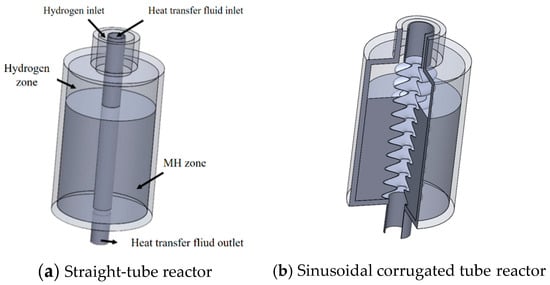
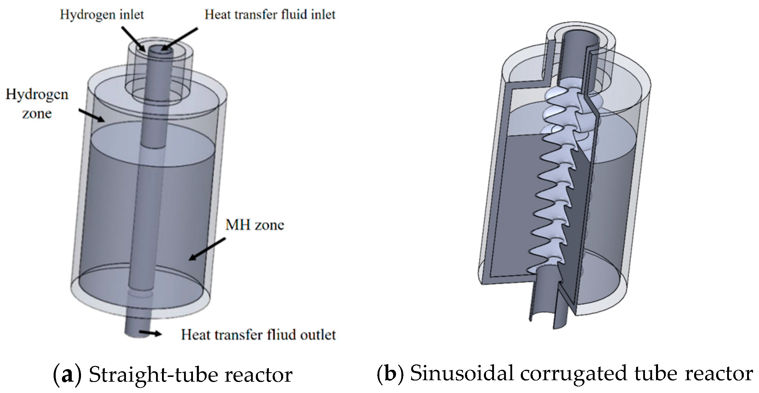
The subject of investigation is a vertically oriented cylindrical MH hydrogen storage vessel with the heat exchange tube running concentrically along the central axis. A plain axial tube serves as the starting reference geometry. It is subsequently replaced by a sinusoidal corrugated tube, and fins are progressively introduced to construct the finned sinusoidal corrugated-tube reactor. This incremental geometric sequence enables the individual and combined contributions of tube corrugation and fin placement to be systematically evaluated. The three-dimensional reactor configurations are shown in Figure 1.
Figure 1.
Three-dimensional schematics of the MH hydrogen storage reactor.
In operation, coolant enters from the top inlet of the sinusoidal corrugated tube and exits from the bottom outlet, traversing the full length of the heat transfer passage. Gaseous hydrogen is fed in the axial direction. The upper interior of the reactor serves as a cylindrical gas plenum, while the lower portion contains the packed MH bed. Hydrogen admitted through the annular inlet at the reactor apex fills the plenum before diffusing downward into the hydride bed.
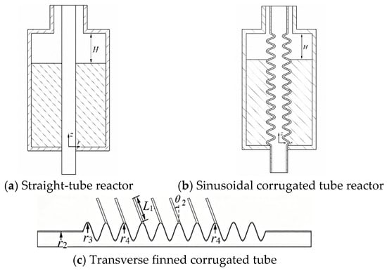
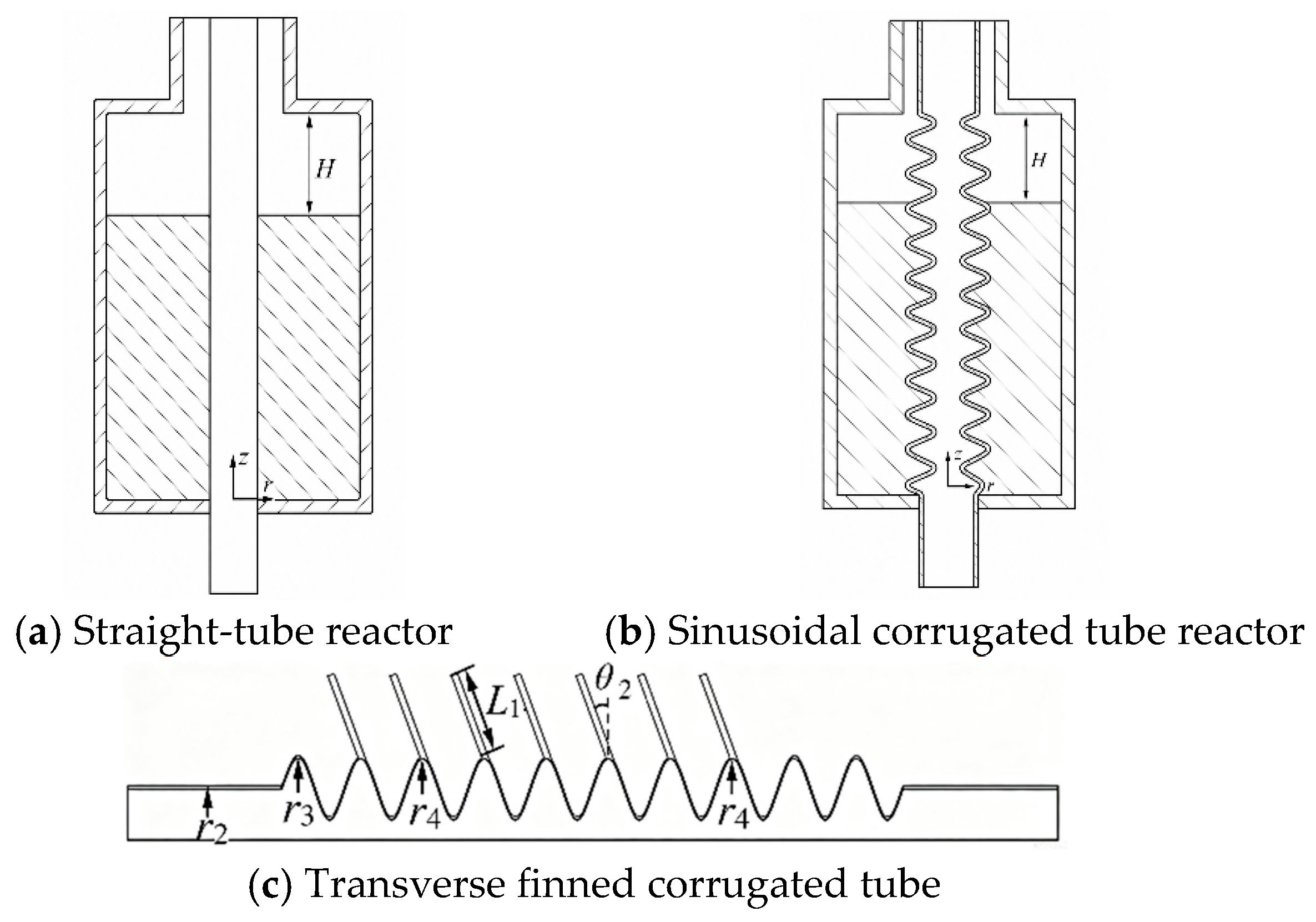
The two-dimensional reactor geometry is illustrated in Figure 2. A cylindrical coordinate framework is employed, with the coordinate origin located at the junction of the reactor axis and the lower boundary of the MH zone. The axial and radial position variables are labeled z and r, respectively, both reported in millimeters. Table 1 lists the geometric parameters together with their physical interpretations. The outer and inner radii of the sinusoidal corrugated tube are defined by the following analytical expressions.
Figure 2.
Two-dimensional schematics of the MH hydrogen storage reactor.
Table 1.
Geometric parameters and physical meanings of the MH hydrogen storage reactor model.
To decouple the effect of internal heat exchange geometry from macroscopic reactor size effects, the principal reactor dimensions were held fixed throughout all computational cases. The reactor had an inner diameter of 25 mm, a wall thickness of 3 mm, and an outer diameter of the top annular inlet of 20 mm, with the axial thickness of the MH bed set to 60 mm [24,25]. Under hydrogen absorption conditions, the outer reactor wall was treated as thermally insulated. Reaction heat generated within the MH bed was dissipated via solid-phase conduction through the porous matrix and via forced convection between the circulating coolant and the inner heat transfer structure. The operating conditions [25,26] were specified as an absorption pressure of pa = 1 MPa, a heat transfer fluid inlet temperature of Tf,a = 293.15 K, and a heat transfer fluid inlet velocity of v = 0.3 m/s. The height of the upper hydrogen region was maintained at H = 20 mm.
LaNi5 is selected as the model hydride material owing to its moderate absorption/desorption thermodynamics, which allow the effects of the heat transfer structure to be isolated from material-dependent thermodynamic factors. The reactor body and fin components are made from aluminum, and pressurized water serves as the working coolant. The thermophysical and kinetic parameters of LaNi5, hydrogen, aluminum, and water are given in Table 2.
Table 2.
Thermophysical and kinetic parameters of LaNi5, H2, aluminum, and water [25,26,27].
To keep the computational cost manageable while retaining the governing physics of heat transfer, mass transport, and chemical reaction, the following modeling assumptions are introduced:
- Geometric and material assumptions: volumetric swelling or contraction of the hydride during absorption is disregarded; the MH powder is assumed to be spatially uniform; bed porosity is considered homogeneous and isotropic; and thermophysical properties of both the hydride and hydrogen gas are treated as temperature-independent constants.
- Transport and phase modeling: hydrogen gas obeys the ideal-gas equation of state; the coolant is modeled as an incompressible Newtonian fluid; and the hydrogen pressure throughout the MH bed is taken as spatially uniform. This assumption is quantitatively justified by a Darcy-law pressure-drop estimate. Using the bed permeability K = 10−8 m2, hydrogen dynamic viscosity μg ≈ 8.9 × 10⁻⁶ Pa·s, a characteristic superficial velocity of v ≈ 8.9 × 10⁻³ m/s derived from the mean absorption rate of 0.86 g/min, and the bed height L = 0.06 m, the estimated pressure drop across the bed is Δp ≈ 0.48 Pa—approximately six orders of magnitude smaller than the absorption pressure of 1 MPa (Δp/p ≈ 4.8 × 10⁻⁷).
- Thermal and gravitational simplifications: local thermal equilibrium is assumed between the gas and solid phases; buoyancy-driven convection and radiative heat transfer within the bed are neglected; and gravitational effects on the hydrogen absorption process are neglected.
2.1. Conservation Equations for the MH Bed and Reactor Structure
The hydrogen absorption process in the MH bed involves coupled gas-phase transport, solid-phase conversion, and unsteady heat transfer. These interacting phenomena are captured through a porous-medium framework incorporating the kinetic and thermodynamic equilibrium relations of LaNi5 [28,29,30].
The conservation equation for hydrogen mass within the porous bed takes the form of Equation (3), with the hydrogen density evaluated from the ideal-gas law as given in Equation (4).
In Equations (3) and (4), ε denotes the bed porosity, ρg the hydrogen density, t the time, the superficial gas velocity in the porous bed, and represents the volumetric rate of hydrogen uptake. The remaining variables are the reactor hydrogen pressure pg, the molar mass of hydrogen Mg, the universal gas constant R = 8.314 J/(mol·K), and the gas temperature Tg.
The corresponding mass balance for the solid hydride phase is expressed by Equation (5) [31].
The variable ρs represents the instantaneous density of the solid MH phase. For LaNi5, the absorption source term is evaluated using the kinetic relation in Equation (6), together with the reaction condition given in Equation (7) [25].
The parameters in Equations (6) and (7) include the absorption rate constant Ca, the equilibrium absorption pressure peq,a, the absorption activation energy Ea, the bed temperature T, and the saturated and hydrogen-free hydride densities ρs,sat and ρemp. The equilibrium pressure is calculated using Equation (8), which describes the van’t Hoff equation [9].
In Equation (8), A and B are the van’t Hoff constants for absorption, where A is dimensionless and B is expressed in K; the reference pressure pref = 1 MPa ensures dimensional consistency of the logarithmic equilibrium pressure correlation.
Although the bed pressure is assumed uniform for the reaction calculation, Darcy’s law is retained to describe the macroscopic seepage velocity associated with pressure-driven gas transport in the porous domain [22,32].
In Equation (9), the permeability of the porous MH bed is denoted by K, while μg represents the dynamic viscosity of hydrogen. The permeability is evaluated from the Kozeny–Carman-type expression in Equation (10) [33].
The term dp in Equation (10) denotes the MH particle diameter. The small MH particle diameter (63 μm) yields a large solid–gas interfacial area that promotes rapid interphase heat exchange, and the moderate reaction enthalpy of LaNi5 precludes the development of significant temperature differences between the solid and gas phases. The local thermal equilibrium (LTE) model [29,34] is therefore adopted to describe heat transfer within the MH bed.
The time-dependent energy equation governing the MH bed is expressed as Equation (11), in which the effective volumetric heat capacity and effective thermal conductivity of the bed are determined respectively by Equations (12) and (13) [35].
The symbols λeff and (ρcp)eff represent the effective thermal conductivity and the volumetric heat capacity of the MH bed, respectively. The heat source is determined by the absorption enthalpy change ΔH and the hydrogen mass source term. The symbols cp,s, cp,g, λs, and λg represent the specific heat capacities and thermal conductivities of the solid hydride and hydrogen, respectively.
Within the aluminum heat exchange tube and surrounding reactor wall, the energy transport is governed solely by unsteady heat conduction, as described by Equation (14) [15].
In this equation, (ρcp)Al and λAl are the volumetric heat capacity and thermal conductivity of aluminum, respectively.
2.2. Conservation Equations for the Heat Transfer Fluid
The hydrodynamic and thermal behavior of the coolant is governed by the coupled conservation equations for mass, linear momentum, and thermal energy. The continuity equation is written as Equation (15) [33].
In Equation (15), ρf is the fluid density and uf is the fluid velocity vector.
The momentum balance of the heat transfer fluid is expressed by Equation (16) [30].
The variables pf and μf represent the fluid pressure and dynamic viscosity, respectively.
The fluid energy equation is given by Equation (17) [19].
Here, (ρcp)f is the volumetric heat capacity of the heat transfer fluid, and λf is its thermal conductivity.
2.3. Initial and Boundary Conditions
The simulation is initialized with spatially uniform distributions of temperature, hydrogen pressure, and hydride density throughout the MH bed. The corresponding initial state is defined by Equation (18) [30].
The initial variables p0, T0, and ρ0 denote the hydrogen pressure, bed temperature, and MH density at t = 0, respectively, while Tf is the inlet temperature of the heat transfer fluid.
At the outer wall of the reactor, homogeneous Neumann conditions (zero normal flux) are imposed on both the temperature and hydrogen pressure fields. These conditions enforce adiabatic insulation at the wall boundary and prohibit hydrogen mass exchange with the external environment [15], as shown in Equation (19).
2.4. Evaluation Indicators for Reactor Performance
The degree of hydride conversion during hydrogen absorption is quantified by the reacted fraction X [17]. Its definition is given in Equation (20).
The hydrogen storage time τa [28] is defined as the elapsed time until the volume-averaged reacted fraction across the bed attains 0.900.
The average hydrogen storage rate va is obtained from the absorbed hydrogen mass over the storage period, as expressed by Equation (21).
In Equation (21), m denotes the total amount of absorbed hydrogen in grams.
The volume fraction of the heat transfer structure φ is expressed by Equation (22):
where Vbe,s is the volume occupied by the heat transfer structure within the MH region, m3; and is the total volume of the MH region without any embedded heat transfer structure, m3.
2.5. Mesh Independence and Numerical Validation
The coolant flow regime was assessed by computing the Reynolds number at the tube inlet. At the operating inlet velocity of v = 0.3 m/s and for the range of tube inlet radii investigated (r2 = 5–7 mm, corresponding to hydraulic diameters of 10–14 mm), the Reynolds number ranges from approximately 2988 to 4183, indicating transitional-to-turbulent flow. The k-ω SST turbulence model was therefore employed to simulate the coolant-side flow field, owing to its established capability in resolving near-wall turbulence and flow separation in internal flows with adverse pressure gradients—conditions representative of sinusoidal corrugated-tube geometries. In Fluent, the first-order implicit transient formulation was adopted, and the SIMPLE algorithm was used to handle the pressure–velocity coupling. The pressure term was discretized using a second-order scheme, while the momentum, turbulent kinetic energy, specific dissipation rate, and energy equations were discretized using the second-order upwind scheme. The residual convergence criteria for the continuity equation, momentum equations, turbulent kinetic energy, and specific dissipation rate were set to 10−8, whereas that for the energy equation was set to 10−10.
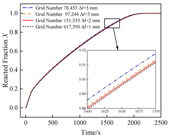
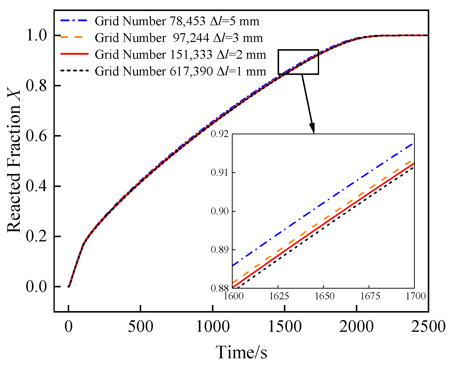
Mesh sensitivity was assessed using a reactor with a plain axial tube. The computational domain encompassed both the MH bed and the heat exchange tube, discretized with a polyhedral unstructured grid generated in Fluent Meshing. Inflation layers were inserted adjacent to the inner tube wall to adequately resolve near-wall fluid velocity and temperature gradients. The maximum element size is denoted by Δl. As illustrated in Figure 3, decreasing Δl from 2 mm to 1 mm results in a cell count increase from 151,333 to 617,390, and the deviation in predicted hydrogen storage time stays below 0.2%. Thus, the mesh with 151,333 cells, corresponding to Δl = 2 mm, was selected as it provides an appropriate compromise between accuracy and computational cost.
Figure 3.
Grid independence verification.
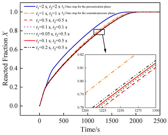
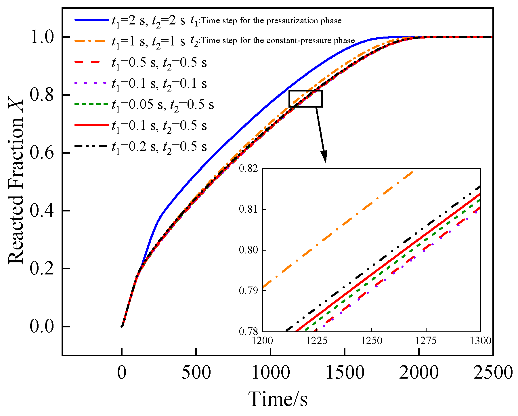
The time-step effect was evaluated separately because the simulations are transient. The symbol t1 denotes the time step used during pressurization, whereas t2 is used during the constant-pressure stage. As illustrated in Figure 4, when t1 = t2, reducing the time step from 0.5 s to 0.1 s yields a variation in storage time of less than 0.1%, confirming that a step size of 0.5 s provides sufficient temporal resolution under constant-pressure conditions. However, pressure variation during pressurization is rapid, and enhanced heat transfer structures can increase the absorption rate, which may lead to numerical instability if a large time step is used. Variable-time-step calculations with t1 < t2 are therefore performed. When t1 is reduced from 0.1 s to 0.05 s, the storage-time deviation remains below 0.2%, and its difference from the t1 = t2 = 0.5 s case is less than 0.6%. Accordingly, t1 = 0.1 s and t2 = 0.5 s are adopted in the subsequent calculations.
Figure 4.
Time-step independence verification.
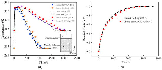
The predictive accuracy of the model is validated against experimental data from a LaNi5 reactor reported by Jemni et al. [36], in which a reactor containing 422 g of alloy was instrumented at r = 15 mm and z = 25 mm. Chung et al. [25] also validated their numerical results using the same dataset. The present predictions are compared with both references in Figure 5. For a heat transfer fluid temperature of 293.00 K, the maximum temperature deviations relative to the experimental and numerical benchmarks are less than 2.5% and 0.3%, respectively. At 313.00 K, the corresponding deviations are below 1% and 0.2%, and the maximum reacted-fraction deviation remains within 1%. Although the corrugated-tube reactor configuration studied in this work differs geometrically from the straight-tube reactor used for model validation, both share an identical set of governing equations, encompassing reaction kinetics and the mass and energy conservation equations for porous media. This commonality lends credibility to the present modeling approach. Nevertheless, it must be acknowledged that direct experimental validation of the finned corrugated-tube geometry itself has not been performed in this study. The present work therefore provides a theoretical baseline, and experimental verification is planned for future work.
Figure 5.
Model validation. (a) Temperature evolution during hydrogen absorption at r = 15 mm and z = 25 mm. (b) Reacted fraction evolution during hydrogen absorption.
3. Results and Discussion
3.1. Comparison of Hydrogen Absorption Performance Among Reactors with Different Finned-Tube Configurations
Longitudinal and transverse fins are first attached to the outer surfaces of the straight tube with r1 = 5 mm and the sinusoidal corrugated tube with r2 = 5 mm. The structural volume fraction is fixed at φ = 15% so that the influence of finned-tube configuration on hydrogen absorption performance can be compared under an identical solid-structure volume constraint.
For the sinusoidal corrugated tube, the corrugation period is maintained at Tbe = 8 mm. The MH region includes the lowest eight wave crests and seven wave troughs. To ensure a consistent comparison, seven fins are adopted for all cases. The fins are installed on the straight tube or on the corrugated tube with r2 = 5 mm, Tbe = 8 mm, and A = 2.5 mm, and the radial distance from the fin outer edge to the reactor axis is fixed at rL = 22 mm. The fin type and installation position are then varied.
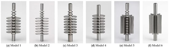
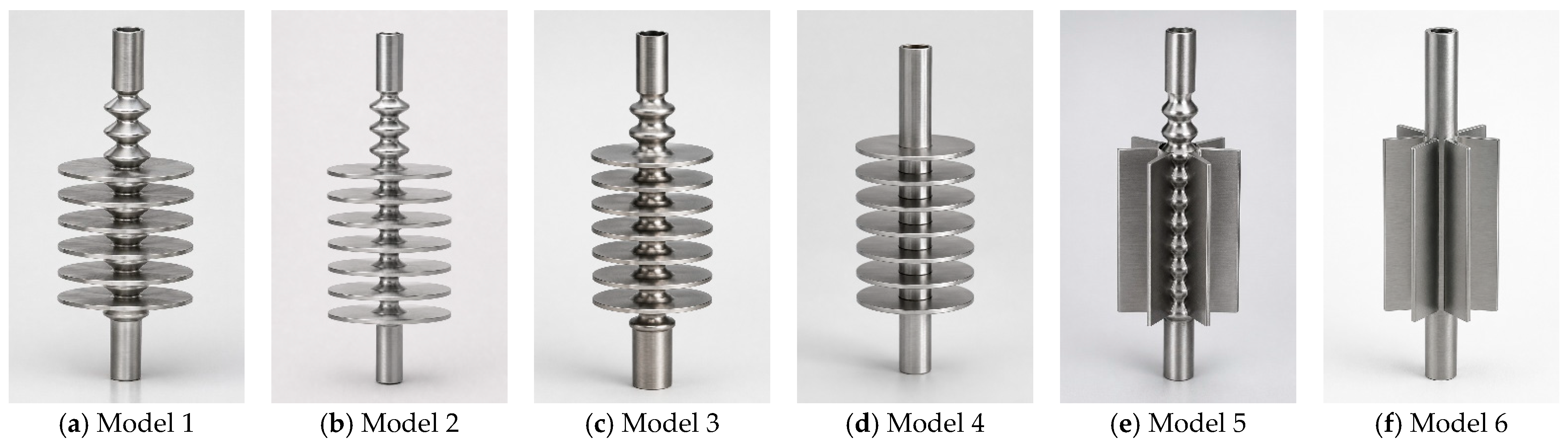
Figure 6 presents the six finned-tube models, all of which place the fins within the MH bed. The straight-tube cases and the longitudinal-finned corrugated-tube case use uniformly distributed fins along the bed height. Model 1 places transverse fins at the wave troughs of the sinusoidal corrugated tube; Model 2 locates the transverse fins on the lower side of seven wave crests; Model 3 locates the transverse fins on the upper side of these wave crests; Model 4 is the transverse-finned straight-tube reactor; Model 5 is the longitudinal-finned corrugated-tube reactor; and Model 6 is the longitudinal-finned straight-tube reactor. The main geometric parameters are listed in Table 3.
Figure 6.
Geometric models of finned tubes with different configurations.
Table 3.
Geometric parameters of different finned-tube models.
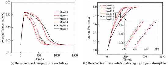
Figure 7 presents the temporal evolution of the volume-averaged bed temperature and reacted fraction for all six finned-tube configurations. In each reactor, the mean bed temperature climbs steeply during the initial absorption stage owing to exothermic reaction heat release, attains a maximum, and subsequently declines as the circulating coolant progressively extracts heat from the bed. The reacted fraction, which quantifies the degree of hydride conversion, increases rapidly at first and then gradually approaches saturation. Models 1 through 4 (transverse-fin configurations) display broadly consistent temporal profiles with no curve crossings throughout the absorption process. In contrast, Models 5 and 6 (longitudinal-fin configurations) initially achieve a lower mean bed temperature and a higher early-stage absorption rate compared with their transverse-fin counterparts. However, their thermal decay rate diminishes at later times, ultimately resulting in a higher mean bed temperature during the late absorption stage.
Figure 7.
Temporal variations in hydrogen storage temperature and reacted fraction for MH reactors with different finned-tube configurations.
Fin addition substantially improves reactor absorption performance. Relative to the unfinned sinusoidal corrugated-tube baseline, Models 1, 2, 3, and 5 achieve reductions in hydrogen storage time ranging from 67.43% to 73.12%. Against the unfinned straight-tube reference, Models 4 and 6 cut storage time by 69.06% and 65.35%, respectively. These figures collectively demonstrate the effectiveness of tube-integrated fins in enhancing the heat dissipation performance of MH reactors.
Direct comparison of Models 4 and 6 shows that Model 4 sustains a higher mean bed temperature beyond 100.0 s but subsequently undergoes more rapid cooling, ultimately reducing storage time by 10.73% relative to Model 6. This performance divergence is attributable to the spatial distribution of conducting solid material. In the longitudinal-fin layout, a disproportionate share of metallic fin volume is concentrated near the tube wall, which promotes heat extraction from the immediately adjacent hydride region while leaving the bed interior relatively thermally isolated. Transverse fins, by contrast, establish radial conductive bridges that penetrate into the central MH zone, compressing the effective conduction length from 10.01 mm to 4.5 mm and thereby strengthening overall heat removal. Model 5 likewise achieves a 30.71% reduction in storage time relative to Model 6, confirming that the sinusoidal corrugated tube geometry inherently provides superior thermal performance over a plain straight tube. Despite recording the lowest peak bed temperature among all six configurations, Model 5 still cannot match the storage times attained by the transverse-finned corrugated-tube variants.
Model 5 achieves a 22.38% reduction in storage time relative to Model 4, confirming that the intrinsic geometry of the heat exchange tube retains a meaningful influence on overall performance even after fins have been incorporated. Models 1 and 2 reduce storage time by 26.26% and 33.91%, respectively, establishing that positioning fins at wave crests is mechanistically more beneficial than placing them at wave troughs. This advantage arises because the corrugated tube promotes intensified secondary flows and recirculation zones predominantly in the crest region, where local convective heat transfer to the coolant is inherently stronger. Model 3 provides a 35.95% reduction in storage time, indicating that upper-side wave-crest placement is more effective than lower-side placement. Since the lower part of the bed already benefits from heat exchange through the reactor wall, its reaction rate is higher than that near the bed surface. Placing the transverse fins on the upper side preferentially improves the reaction in the upper region of the bed while only slightly weakening that in the lower region.
On the basis of these findings, Model 3 is selected as the superior configuration, recording a hydrogen storage time of 330.5 s and a mean absorption rate of 0.78 g/min. Subsequent geometric optimization is built upon Model 3, with Model 4 (storage time 516.0 s, mean rate 0.50 g/min) retained as the transverse-finned straight-tube reference for comparative assessment.
3.2. Optimization of Ccorrugated-Tube Inlet Radius in the Finned Corrugated-Tube Reactor
Building on Model 3 as the reference geometry, the influence of corrugated-tube inlet radius is systematically evaluated at r2 = 5, 6, and 7 mm. The corrugation period, structural volume fraction, and fin outer-edge radius are kept at Tbe = 8 mm, φ = 15%, and rL = 22 mm, respectively. Because the volume fraction constraint is enforced, any variation in r2 necessitates corresponding modifications to transverse fin length and thickness. The study therefore captures the interdependent effects of tube radius, fin dimensions, and bed radial depth simultaneously. The geometric parameters of the three models are summarized in Table 4.
Table 4.
Geometric parameters of transverse-finned sinusoidal corrugated-tube models with different inlet radii.
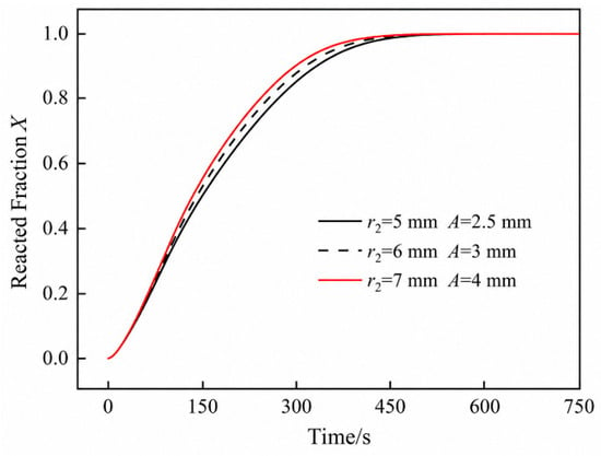
Figure 8 shows the reacted-fraction evolution for the finned sinusoidal corrugated-tube reactors with different inlet radii. The reacted fraction, which quantifies the degree of hydride conversion, increases more rapidly as r2 increases, indicating progressively enhanced absorption kinetics. For r2 = 5, 6, and 7 mm, the hydrogen storage times are 330.5, 314.0, and 299.0 s, respectively. Relative to r2 = 5 mm, the storage time decreases by 4.99% at r2 = 6 mm and by 9.53% at r2 = 7 mm. This performance gain is attributable to the combined effect of a wider internal coolant passage, a thinner radial hydride layer, and adjusted fin dimensions mandated by the constant-volume constraint—factors that collectively intensify heat extraction from the bed. The reactor at r2 = 7 mm is selected for the subsequent fin-geometry optimization, and its average hydrogen storage rate is 0.86 g/min. It should be noted that the performance improvement observed with increasing r2 is valid only within the investigated range of 5–7 mm and does not imply a monotonically beneficial trend for arbitrarily large tube radii. As with any geometric parameter, diminishing returns are expected: beyond a certain threshold, further enlargement of the tube radius would progressively reduce the hydride packing volume, leading to a pronounced decrease in total hydrogen storage capacity while the kinetic gains progressively saturate. The selection of r2 = 7 mm therefore represents a balanced choice between absorption kinetics and hydride inventory under the geometric constraints and volume fraction limitation (φ = 15%) of the present reactor design.
Figure 8.
Reacted-fraction evolution in finned sinusoidal corrugated-tube reactors with different inlet radii.
For reference, a bare sinusoidal corrugated-tube reactor without fins, operating at r2 = 7 mm, Tbe = 8 mm, and A = 4 mm, yields a mean storage rate of only 0.38 g/min. The inlet-radius-optimized finned corrugated-tube reactor reduces storage time by 62.74% and increases the mean rate by 126.89% relative to this finless baseline, with a 5.49 percentage-point increase in structural volume fraction. Against Model 4, storage time is reduced by 42.05% and the mean rate increases by 72.60%, while the structural volume fraction remains at the same 15% level.
3.3. Effect of Transverse Fin Geometry on Reactor Performance
In the following parametric study, the structural volume fraction is maintained at φ = 15%, and the sinusoidal corrugated tube is defined by r2 = 7 mm, Tbe = 8 mm, and A = 4 mm. The transverse fin dimensions are then systematically varied to further refine the integrated thermal enhancement provided by the fin-corrugated-tube assembly.
3.3.1. Optimization of Transverse Fin Length
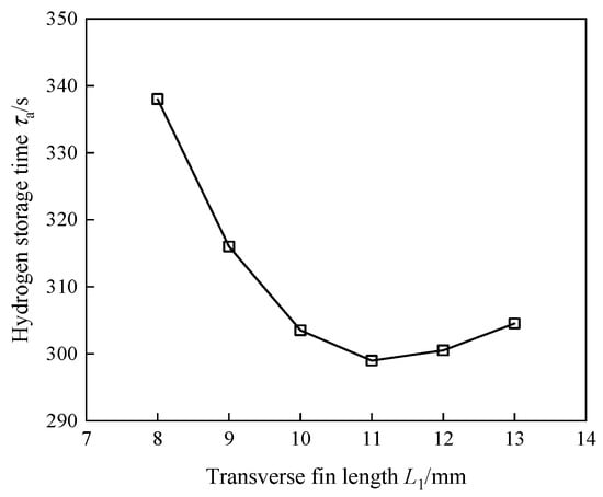
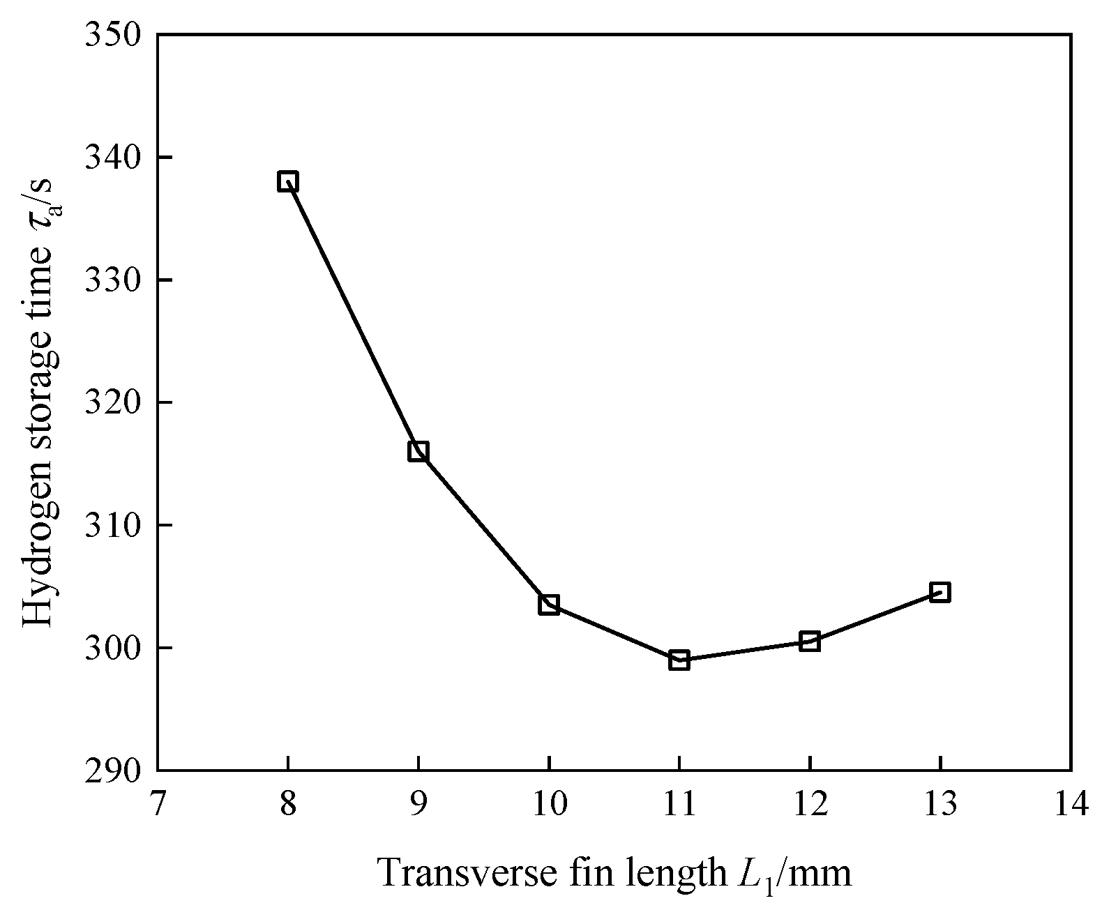
With the structural volume fraction held constant, the transverse fin length L1 is varied from 8 to 13 mm. To satisfy the constant-volume constraint, the fin thickness is correspondingly set to 1.21, 1.05, 0.92, 0.81, 0.72, and 0.65 mm for each case. The corresponding geometric parameters are summarized in Table 5.
Table 5.
Geometric parameters of transverse-finned sinusoidal corrugated-tube models with different fin lengths (r2 = 7 mm, Tbe = 8 mm, A = 4 mm).
As shown in Figure 9, storage time falls monotonically as L1 rises from 8 to 11 mm, then rebounds when L1 is extended beyond this value. The global minimum storage time therefore occurs at L1 = 11 mm.
Figure 9.
Variation in hydrogen storage time with transverse fin length.
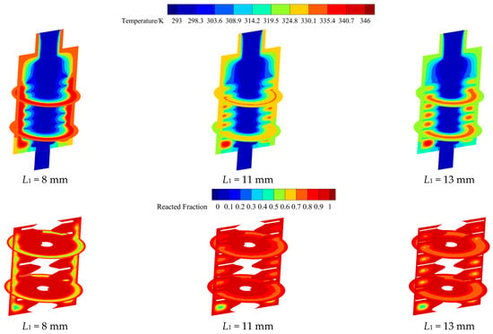
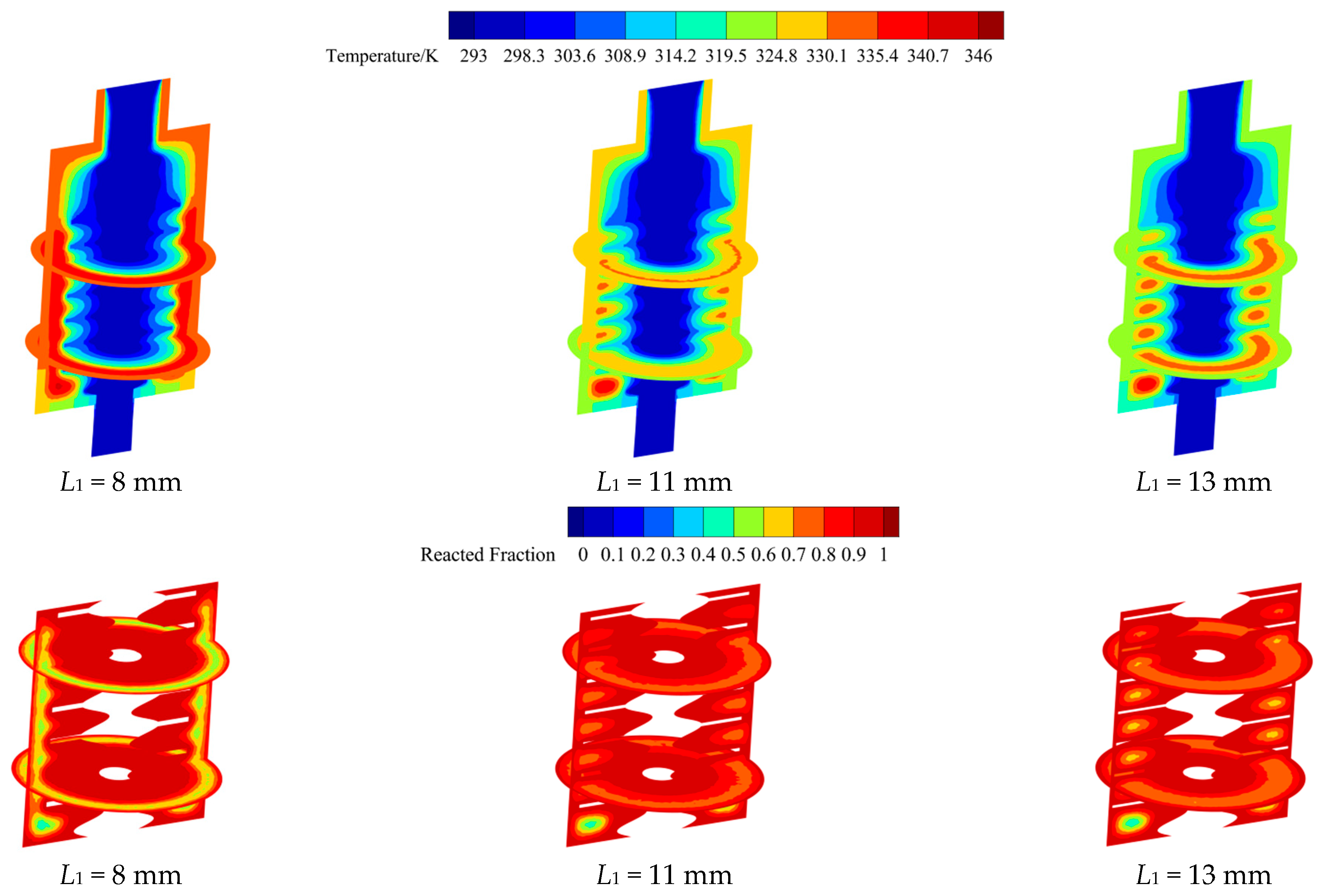
Figure 10 presents the temperature and reacted-fraction contours at 300.0 s for representative fin lengths. When L1 = 8 mm, a large high-temperature and low-conversion zone remains near the reactor wall and at the lower part of the bed, with temperatures of approximately 335.40–340.70 K and reacted fractions of 0.5–0.7. When L1 = 11 mm, the high-temperature region is greatly reduced except near the bed bottom; the temperature decreases to approximately 324.80–335.40 K, and the reacted fraction increases to 0.7–0.9. When L1 = 13 mm, the temperature near the reactor wall decreases further, but a high-temperature zone develops between adjacent fins and the local reacted fraction decreases.
Figure 10.
Temperature and reacted-fraction contours under different transverse fin lengths at 300.0 s.
This non-monotonic behavior reflects a fundamental trade-off between geometric reach and thermal conductance. When fins are short, the annular hydride zone between the outer wall and the corrugated tube is poorly connected to the main heat removal path, impeding efficient dissipation of reaction heat. Extending L1 brings fin tips progressively closer to the wall, establishing a more direct conductive pathway and accelerating heat extraction. Beyond the optimum, however, the volume-fraction constraint demands that additional length gains be offset by proportional fin thinning, which reduces per-fin conductance, slows absorption in the inter-fin hydride zone, and increases storage time. Therefore, L1 = 11 mm represents the optimal balance between radial heat transfer reach and fin conduction resistance.
Among the surveyed fin lengths, L1 = 8 mm yields the poorest absorption kinetics, with a storage time of 338.0 s—11.54% longer than the optimum at L1 = 11 mm. Accordingly, L1 = 11 mm is fixed for the subsequent inclination-angle investigation.
3.3.2. Optimization of Transverse Fin Inclination Angle
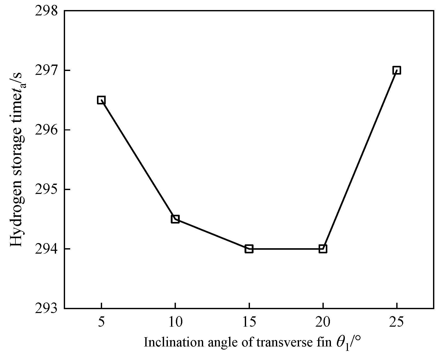
In the transverse-finned sinusoidal corrugated-tube reactor, a persistently sluggish conversion zone remains near the bed base, while the hydride situated between adjacent fins reacts considerably faster, as is evident from Figure 11. To mitigate this spatial heterogeneity, the fin inclination angle θ1 is swept between 5° and 25°; for each angle, the projected fin length and fin thickness are adjusted accordingly to maintain the structural volume fraction at φ = 15%.
Figure 11.
Variation in hydrogen storage time with transverse fin inclination angle.
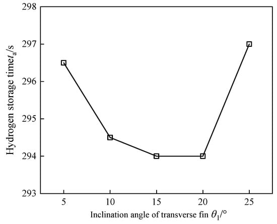
Figure 11 plots hydrogen storage time as a function of θ1. Storage time decreases as the angle rises from 5° toward an intermediate optimum, then increases again at larger values. The shortest hydrogen storage time of 294.0 s is obtained at θ1 = 15° and 20°.
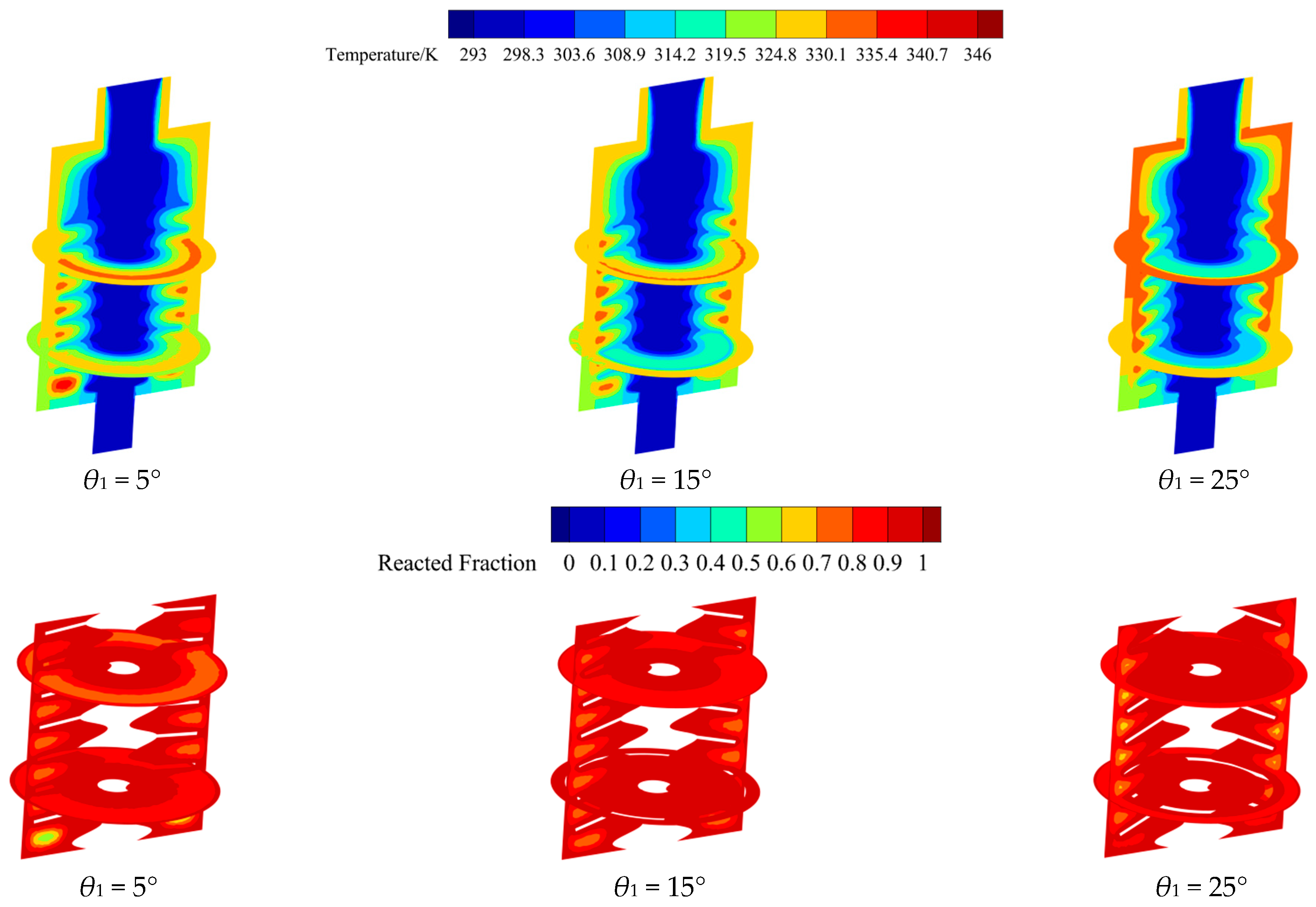
The temperature and reacted-fraction contours at 300.0 s for different inclination angles are shown in Figure 12. At θ1 = 15°, the temperature near the fins is mainly distributed within 319.50–335.40 K, and the reacted fraction in this region reaches 0.7–0.9. At θ1 = 5°, a relatively large high-temperature and low-conversion region remains at the bed bottom. At θ1 = 25°, the bottom temperature is reduced, but the temperature near the reactor wall and fins increases, and areas with reacted fraction below 0.7 appear. This behavior arises from the redistribution of fin coverage along the bed height. A small angle places the uppermost fin close to the bed surface and enhances the reaction in the upper bed region, but it leaves insufficient heat transfer enhancement near the bottom. An excessively large angle increases the distances from the fins to the wall and the bed surface, thereby weakening heat removal in those regions. An intermediate inclination angle can therefore reduce the bottom dead zone without markedly impairing the surface reaction.
Figure 12.
Temperature and reacted-fraction contours under different transverse fin inclination angles at 300.0 s.
The total spread in storage time across all tested angles is below 1.3%, confirming that fin inclination exerts only a modest influence on the globally averaged absorption rate. Nevertheless, strategic angle selection demonstrably enhances spatial homogeneity in both temperature and reacted fraction by suppressing the underperforming zone at the bed base. Since θ1 = 15° and θ1 = 20° yield identical minimum storage times, θ1 = 15° is adopted as the preferred angle to minimize structural complexity. Accordingly, the configuration with mm, mm, and θ1 = 15° is regarded as the optimized finned sinusoidal corrugated-tube reactor.
For this optimized configuration, the trade-off between thermal enhancement and usable hydrogen storage capacity is further examined. The conventional straight-tube reactor has a tube radius of 5 mm and a heat transfer structure volume fraction of approximately 4%, whereas the optimized reactor has a structural volume fraction of 15%. After hydrogen absorption is completed, the total hydrogen storage capacity decreases from 5.37 g to 4.76 g, corresponding to a reduction of approximately 11.4%. However, the hydrogen storage time is shortened from 1419 s to 294 s, representing a reduction of 79.28%. These results demonstrate that the kinetic improvement achieved by the proposed structure far outweighs the moderate loss in storage capacity. Therefore, for compact MH hydrogen storage reactors requiring rapid charging and efficient thermal management, a moderate reduction in volumetric storage capacity represents a rational engineering trade-off for substantial improvement in heat transfer performance.
4. Conclusions and Outlook
This study proposed a transverse-finned sinusoidal corrugated-tube reactor and numerically investigated its hydrogen absorption performance in an MH bed. The main conclusions are as follows:
- Among the investigated configurations, the transverse-finned sinusoidal corrugated-tube reactor exhibited the best overall hydrogen absorption performance. Placing the transverse fins on the upper side of the sinusoidal wave crests provided the most effective thermal enhancement. Under this configuration, the hydrogen storage time was 330.5 s and the mean hydrogen absorption rate reached 0.78 g/min, corresponding to a 35.95% reduction in storage time compared with the transverse-finned straight-tube reactor.
- Increasing the corrugated-tube inlet radius effectively improved the hydrogen absorption performance. When r2 was increased from 5 to 7 mm, the hydrogen storage time decreased from 330.5 to 299.0 s, while the mean hydrogen absorption rate increased to 0.86 g/min. Compared with the finless corrugated-tube reactor and the transverse-finned straight-tube reactor, the optimized configuration reduced the hydrogen storage time by 62.74% and 42.05%, respectively. Meanwhile, the structural volume fraction was maintained at 15%, indicating that the performance improvement was achieved without further increasing the structural volume fraction.
- The transverse fin length had a significant influence on the thermal response and reaction uniformity of the MH bed. The optimal fin length was L1 = 11 mm, which reduced the hydrogen storage time by 11.54% compared with L1 = 8 mm. In contrast, the fin inclination angle had a limited effect on the overall storage time, with variations below 1.3%, but it helped improve the spatial uniformity of temperature and reacted fraction, especially in the lower region of the MH bed.
- The enhanced performance of the proposed reactor mainly results from the coupling between corrugated-tube-induced convective disturbance and fin-assisted heat conduction. This coupled heat transfer mechanism shortens the heat transfer path, improves the thermal uniformity of the MH bed, and accelerates the hydrogen absorption process.
In summary, the finned sinusoidal corrugated-tube reactor constitutes a viable and high-performance structural solution for advancing MH hydrogen storage technology. The computational findings reported in this study provide a quantitative parameter reference and theoretical foundation for subsequent experimental validation and prototype engineering. Owing to its rapid hydrogen absorption/desorption kinetics and compact thermal architecture, the proposed design holds particular promise for applications requiring fast hydrogen charging/discharging cycles and space-efficient integration, including lightweight hydrogen fuel-cell vehicles and portable energy supply units. It should be noted that pressure drop cannot be neglected in large-scale systems, high-flow-rate operating conditions, or multi-tube parallel configurations, where its influence may become significantly more pronounced. Within the scope of the present study, however, the optimized corrugated-tube structure substantially enhances heat transfer and improves the hydrogen absorption rate while only slightly increasing flow resistance. Therefore, in practical reactor design, accepting a modest increase in pumping power in exchange for a considerable improvement in absorption kinetics represents a reasonable and well-established engineering trade-off. The inherent safety and high volumetric energy density of solid-state hydrogen storage further motivate the exploration of this structure for distributed power generation and microgrid energy buffering, where thermally stable operation is essential. The parametric study reported here follows a sequential one-factor-at-a-time procedure, which provides physically interpretable performance trends for each design variable. However, owing to the interdependence among the geometric parameters, this approach does not guarantee identification of a globally optimal solution. The identified configuration therefore represents the best-performing design within the studied parameter ranges rather than a guaranteed global optimum. Future work should consider applying systematic multi-objective optimization frameworks—such as response surface methodology or genetic algorithms—to more comprehensively explore the full design space and further refine the recommended configuration. Furthermore, the present study focuses on the hydrogen absorption process. The underlying thermal enhancement mechanisms—namely, corrugated-tube-induced convective intensification and fin-mediated solid-phase conduction—are, however, theoretically applicable to hydrogen desorption as well, where efficient heat supply to the bed interior is the governing bottleneck. A systematic numerical investigation of the desorption process and full absorption–desorption cycling behavior is currently underway and will be reported in a subsequent study. Future research will also focus on constructing an experimental test rig to validate the performance of the sinusoidal corrugated-tube configuration under realistic operating conditions.
Author Contributions
Conceptualization, H.Z. and M.G.; Methodology, H.Z. and M.G.; Software, H.Z.; Validation, Z.C.; Formal analysis, H.Z. and S.W.; Investigation, H.Z. and J.S.; Resources, S.W.; Data curation, Z.C.; Writing—original draft, H.Z.; Writing—review & editing, S.W.; Visualization, Z.C.; Supervision, M.G.; Project administration, J.S. and M.G.; Funding acquisition, M.G. All authors have read and agreed to the published version of the manuscript.
Funding
This work was supported by the Natural Science Foundation of Shandong Province of China (No. ZR2023ME025).
Data Availability Statement
The original contributions presented in this study are included in the article. Further inquiries can be directed to the corresponding author.
Conflicts of Interest
The authors declare no conflict of interest.
Nomenclature
| Abbreviations | Greek symbols | ||
| LTE | Local thermal equilibrium approximation | ΔH | Absorption reaction enthalpy, J/mol |
| MH | Metal hydride | ε | Bed porosity |
| Symbols | θ1 | Transverse fin inclination angle, ° | |
| A | Amplitude of sinusoidal corrugation | λ | Thermal conductivity, W/(m·K) |
| Aa | van’t Hoff constant for absorption | μ | Dynamic viscosity, kg/(m·s) |
| Ba | van’t Hoff constant for absorption, K | ρ | Density, kg/m3 |
| Ca | Absorption rate constant, 1/s | τa | Hydrogen storage time, s |
| cp | Specific heat capacity, J/(kg·K) | φ | Heat transfer structure volume fraction, % |
| dp | MH particle diameter, μm | Subscripts and Superscripts | |
| Ea | Absorption activation energy, J/mol | 0 | Initial condition |
| K | MH bed permeability, m2 | Al | Aluminum |
| L1 | Transverse fin length, mm | a | Absorption |
| M | Molar mass, kg/mol | be | Corrugation period |
| Volumetric hydrogen mass source term, kg/(m3·s) | eff | Effective property | |
| p | Pressure, Pa | emp | Hydrogen-free state |
| r | Radial coordinate, mm | eq | Equilibrium state |
| R | Universal gas constant, J/(mol·K) | f | Fluid phase |
| T | Temperature, K | g | Gas phase |
| Tbe | Corrugation period, mm | L | Fin outer edge |
| Hydrogen velocity in the MH bed, m/s | ref | Reference condition | |
| va | Average hydrogen storage rate, g/min | s | Solid |
| X | Reacted fraction | sat | Saturated condition |
References
- Li, Z.; Zhang, M.; Xu, H. Revealing the Roles of Heat Transfer, Thermal Dynamics, and Reaction Kinetics in Hydrogenation/Dehydrogenation Processes for Mg-Based Metal Hydride Hydrogen Storage. Energies 2025, 18, 2924. [Google Scholar] [CrossRef] [Scilit]
- Song, J.; Wang, S.; Zhang, H.; Guo, W.; Lyu, Q.; Yang, L.; Gao, M. Research Status and Progress of Thermal Management Technology in Metal Hydride Hydrogen Absorption/Desorption Processes. Clean Coal Technol. 2025, 31, 97–113. [Google Scholar]
- Kudiiarov, V.; Elman, R.; Pushilina, N.; Kurdyumov, N. State of the Art in Development of Heat Exchanger Geometry Optimization and Different Storage Bed Designs of a Metal Hydride Reactor. Materials 2023, 16, 4891. [Google Scholar] [CrossRef] [Scilit] [PubMed]
- Maggini, M.; Facci, A.L.; Falcucci, G.; Ubertini, S. Increasing the Metal-Hydride Power Density Using Phase-Change Materials, Advanced Thermal Supports, and Expanded Graphite Nano-Particles. Energies 2026, 19, 185. [Google Scholar] [CrossRef] [Scilit]
- Ye, Y.; Zhang, Z.; Zhang, Y.; Liu, J.; Yan, K.; Cheng, H. Structure and Performance Optimization of a MgH2-Based Array Hydrogen Storage Reactor. Renew. Energy 2026, 256, 124319. [Google Scholar] [CrossRef] [Scilit]
- Wang, J.; Dai, M.; Liu, J.; Wu, Z.; Zhang, Z.; Grbović Novaković, J.; Yang, F. A Novel Design for Fin Profile in Metal Hydride Reactor towards Heat Transfer Enhancement: Theoretical Derivations and Analysis. J. Energy Storage 2023, 72, 108570. [Google Scholar] [CrossRef] [Scilit]
- Zhu, J.; Lin, X.; Lv, L.; Li, M.; Luo, Q.; Kudiiarov, V.N.; Liu, W.; Leng, H.; Han, X.; Ma, Z. The Relationship between Thermal Management Methods and Hydrogen Storage Performance of the Metal Hydride Tank. J. Mater. Sci. Technol. 2024, 203, 66–77. [Google Scholar] [CrossRef] [Scilit]
- Kamran, M.; Turzyński, M. Exploring Hydrogen Energy Systems: A Comprehensive Review of Technologies, Applications, Prevailing Trends, and Associated Challenges. J. Energy Storage 2024, 96, 112601. [Google Scholar] [CrossRef] [Scilit]
- Tong, L.; Xiao, J.; Yang, T.; Bénard, P.; Chahine, R. Complete and Reduced Models for Metal Hydride Reactor with Coiled-Tube Heat Exchanger. Int. J. Hydrogen Energy 2019, 44, 15907–15916. [Google Scholar] [CrossRef] [Scilit]
- Meng, X.; Wu, Z.; Bao, Z.; Yang, F.; Zhang, Z. Performance Simulation and Experimental Confirmation of a Mini-Channel Metal Hydrides Reactor. Int. J. Hydrogen Energy 2013, 38, 15242–15253. [Google Scholar] [CrossRef] [Scilit]
- Muthukumar, P.; Singhal, A.; Bansal, G.K. Thermal Modeling and Performance Analysis of Industrial-Scale Metal Hydride Based Hydrogen Storage Container. Int. J. Hydrogen Energy 2012, 37, 14351–14364. [Google Scholar] [CrossRef] [Scilit]
- Wu, Z.; Yang, F.; Zhu, L.; Feng, P.; Zhang, Z.; Wang, Y. Improvement in Hydrogen Desorption Performances of Magnesium Based Metal Hydride Reactor by Incorporating Helical Coil Heat Exchanger. Int. J. Hydrogen Energy 2016, 41, 16108–16121. [Google Scholar] [CrossRef] [Scilit]
- Guan, S.; Gao, X.; Wang, Y.; Li, F.; Chen, J.; Wang, D.; Zheng, L.; Wu, L.; Zhang, Z. Design Optimization and Performance Evaluation of Spherical Hydrogen Storage Reactor. Renew. Sustain. Energy Rev. 2025, 211, 115228. [Google Scholar] [CrossRef] [Scilit]
- Chen, Z.; Yan, S.; Zhang, W.; Yang, L.; Zhou, S.; Gao, M. Numerical Simulation on Effect of Reaction Dead Zone Optimization on Hydrogen Storage Performance in Metal Hydride Hydrogen Storage Reactor. J. Chin. Soc. Power Eng. 2025, 45, 474–480. [Google Scholar]
- Bai, X.-S.; Yang, W.-W.; Tang, X.-Y.; Yang, F.-S.; Jiao, Y.-H.; Yang, Y. Hydrogen Absorption Performance Investigation of a Cylindrical MH Reactor with Rectangle Heat Exchange Channels. Energy 2021, 232, 121101. [Google Scholar] [CrossRef] [Scilit]
- Afzal, M.; Sharma, P. Design and Computational Analysis of a Metal Hydride Hydrogen Storage System with Hexagonal Honeycomb Based Heat Transfer Enhancements—Part A. Int. J. Hydrogen Energy 2021, 46, 13116–13130. [Google Scholar] [CrossRef] [Scilit]
- Bi, W.; Hou, Y.; Wan, J.; Hu, J.; Yu, M.; Xu, X.; Sun, Y.; Zhou, Q.; Xie, S.; Li, T.; et al. Influence of Corrugated Tube Structure and Flow Rate on the Hydrogen Absorption Performance of Metal Hydride Reactor and Structural Optimization. Process Saf. Environ. Prot. 2024, 190, 97–109. [Google Scholar] [CrossRef] [Scilit]
- Yang, W.; Ye, Y.; Cheng, H.; Liu, J.; Yan, K.; Miao, H. Performance Optimization of a U-Tube Heat Exchanger Type Hydrogen Storage Reactor with a Novel Fin Structure. Int. J. Hydrogen Energy 2024, 82, 272–280. [Google Scholar] [CrossRef] [Scilit]
- Wang, H.; Yi, G.; Ye, J.; Feng, X.; Li, Z.; Wang, S.; Gao, Z. Intensification of Hydrogen Absorption Process in Metal Hydride Devices with Novel Corrugated Fins: A Validated Numerical Study. J. Alloys Compd. 2022, 926, 166759. [Google Scholar] [CrossRef] [Scilit]
- Krishna, K.V.; Pandey, V.; Maiya, M.P. Topology Optimized Fin Structures for Performance Enhancement of Metal Hydride Reactors. Int. J. Hydrogen Energy 2024, 60, 491–502. [Google Scholar] [CrossRef] [Scilit]
- Liu, X.; Yi, X.; Ren, Q.; Zheng, B.; Liang, F. Performance Evaluation of a Metal Hydride Reactor Using Metal-Based Composite Pellets. Int. Commun. Heat Mass Transf. 2026, 172, 110343. [Google Scholar] [CrossRef] [Scilit]
- Bai, X.; Yang, W.; Tang, X.; Dai, Z.; Yang, F. Parametric Optimization of Coupled Fin-Metal Foam Metal Hydride Bed towards Enhanced Hydrogen Absorption Performance of Metal Hydride Hydrogen Storage Device. Energy 2022, 243, 123044. [Google Scholar] [CrossRef] [Scilit]
- El Mghari, H.; Huot, J.; Xiao, J. Analysis of Hydrogen Storage Performance of Metal Hydride Reactor with Phase Change Materials. Int. J. Hydrogen Energy 2019, 44, 28893–28908. [Google Scholar] [CrossRef] [Scilit]
- Krishna, K.V.; Pandey, V.; Maiya, M.P. Bio-Inspired Leaf-Vein Type Fins for Performance Enhancement of Metal Hydride Reactors. Int. J. Hydrogen Energy 2022, 47, 23694–23709. [Google Scholar] [CrossRef] [Scilit]
- Chung, C.A.; Ho, C.J. Thermal-Fluid Behavior of the Hydriding and Dehydriding Processes in a Metal Hydride Hydrogen Storage Canister. Int. J. Hydrogen Energy 2009, 34, 4351–4364. [Google Scholar] [CrossRef] [Scilit]
- Chang, H.; Tao, Y.B.; Wang, W.Y. Numerical Study on Storage Performance of Metal Hydride Reactors with Multiple Spiral Fins. Int. J. Hydrogen Energy 2023, 48, 35170–35184. [Google Scholar] [CrossRef] [Scilit]
- Wang, H.; Prasad, A.K.; Advani, S.G. Hydrogen Storage Systems Based on Hydride Materials with Enhanced Thermal Conductivity. Int. J. Hydrogen Energy 2012, 37, 290–298. [Google Scholar] [CrossRef] [Scilit]
- Chandra, S.; Sharma, P.; Muthukumar, P.; Tatiparti, S.S.V. Modeling and Numerical Simulation of a 5 kg LaNi5-Based Hydrogen Storage Reactor with Internal Conical Fins. Int. J. Hydrogen Energy 2020, 45, 8794–8809. [Google Scholar] [CrossRef] [Scilit]
- Mohan, G.; Maiya, M.P.; Murthy, S.S. Performance Simulation of Metal Hydride Hydrogen Storage Device with Embedded Filters and Heat Exchanger Tubes. Int. J. Hydrogen Energy 2007, 32, 4978–4987. [Google Scholar] [CrossRef] [Scilit]
- Bai, X.-S.; Yang, W.-W.; Tang, X.-Y.; Yang, F.-S.; Jiao, Y.-H.; Yang, Y. Optimization of Tree-Shaped Fin Structures towards Enhanced Absorption Performance of Metal Hydride Hydrogen Storage Device: A Numerical Study. Energy 2021, 220, 119738. [Google Scholar] [CrossRef] [Scilit]
- Lewis, S.D.; Chippar, P. Numerical Investigation of Hydrogen Absorption in a Metal Hydride Reactor with Embedded Embossed Plate Heat Exchanger. Energy 2020, 194, 116942. [Google Scholar] [CrossRef] [Scilit]
- Wang, W.; Wang, M.; Wang, J.; Chen, X.; Xu, W.; Wang, W. Numerical Study on Hydrogen Desorption Performance of a New MgH2 Solid-State Hydrogen Storage Device. Int. J. Hydrogen Energy 2024, 86, 530–541. [Google Scholar] [CrossRef] [Scilit]
- Aadhithiyan, A.; Bhargav, K.; Sreeraj, R.; Anbarasu, S. Multi-Objective Design Optimization of Hydride Hydrogen Storage Reactor Structured with Finned Helical Tubes Based on Energetic and Economic Analyses. J. Energy Storage 2023, 64, 107194. [Google Scholar] [CrossRef] [Scilit]
- Hasnain, M.; Sezer, H.; Mason, J.H. Mathematical Modeling of Heat and Mass Transfer in Metal Hydride Hydrogen Storage Systems: A Comprehensive Review. Renew. Sustain. Energy Rev. 2026, 226, 116294. [Google Scholar] [CrossRef] [Scilit]
- Wang, Y.; Zhang, H.; He, S.; Wang, W.; Gao, M.; Koltsova, E.; Vasilenko, V. Dynamic Analysis and Control Optimization of Hydrogen Supply for the Proton Exchange Membrane Fuel Cell and Metal Hydride Coupling System with a Hydrogen Buffer Tank. Energy Convers. Manag. 2023, 291, 117339. [Google Scholar] [CrossRef] [Scilit]
- Jemni, A.; Ben Nasrallah, S.; Lamloumi, J. Experimental and Theoretical Study of a Metal-Hydrogen Reactor. Int. J. Hydrogen Energy 1999, 24, 631–644. [Google Scholar] [CrossRef] [Scilit]

Disclaimer/Publisher’s Note: The statements, opinions and data contained in all publications are solely those of the individual author(s) and contributor(s) and not of MDPI and/or the editor(s). MDPI and/or the editor(s) disclaim responsibility for any injury to people or property resulting from any ideas, methods, instructions or products referred to in the content. |
© 2026 by the authors. Licensee MDPI, Basel, Switzerland. This article is an open access article distributed under the terms and conditions of the Creative Commons Attribution (CC BY) license.