


Abstract
In order to solve the easily scalable problem of evaporative condensing equipment, re-search was conducted on the development of a new type of self-priming scaling evaporative condenser with a built-in electrochemical scale absorber which changes the traditional water quality treatment cycle method from “preventing scaling” to “self-priming scaling”, integrating treatment devices and an evaporative condenser in order to realize the integration and modularization of the equipment. Experimental results show that the new self-priming scaling evaporative condenser has a condensing temperature range of 36.7~38.9 °C, heat rejection range of 716.69~768.66 kW, and, under different load rates, a condensing temperature range of 22.7~36.7 °C. The new self-priming scaling evaporative condenser system’s energy efficiency ratio COP has a range of 3.26~3.44. The coefficient of performance IPLV is 3.9, which exceeds the design index value. After the unit ECT electrochemistry meter is turned on, it effectively reduces the concentration multiplier of water quality: the total hardness increase per minute is reduced from 0.4 mg/L to 0.23 mg/L, a reduction of 42.5%. Turning on the electrochemistry meter also effectively reduces the increase in the total hardness and reduces the occurrence of scaling in the evaporative condenser unit.
1. Introduction
Building energy consumption in China occupies a sizeable proportion of the country’s total social energy consumption, with air conditioning system energy consumption representing a major component [1]. The national “carbon peak, carbon neutral” goal was proposed in order to guide China’s refrigeration and air conditioning industry toward a greener, lower-carbon, and energy-saving future [2].
In the field of data centers, along with the rise of the big data era, the total heat load and heat density of data centers have risen sharply, and the heat generation of a single cabinet is now 20–30 kW [3]. Because the air conditioning systems of data centers needs to run uninterruptedly throughout the year, the energy consumption of air conditioning systems accounts for about 40% of the energy consumption of the entire data center [4]. The vast majority of data center air conditioning methods are still dominated by traditional mechanical refrigeration air conditioning [5]. In order to reduce the energy consumption of data center air conditioning systems, we must start from the condenser; air-cooled and water-cooled condensers have a low cooling efficiency, and their overall energy consumption is high. The use of evaporative condensers is proposed to solve these problems.
With the deepening of research, different forms and structures of evaporative condensers have emerged, and researchers have begun to study evaporative condensers with different tube types. Chuklin [6] was the first to study plate evaporative condensers. Fisher et al. [7] studied the combination of evaporative condensers in the form of light tubes or finned tubes with cooling towers and obtained an empirical correlation formula for the heat transfer film coefficient. P. J. Erens [8] compared different forms of evaporative condensers and proposed that adding plastic fillers has a significant impact on improving heat transfer performance. This is the theoretical basis for increasing heat transfer efficiency by installing fillers in evaporative condensers nowadays.
In terms of theoretical research on evaporative condensers, Boris Halasz [9] proposed a general mathematical model for cooling towers, evaporative condensers, etc., but this model is too simple to match the actual process. U. Wittek [10] studied the improvement of cooling tower structure design to enhance heat and mass transfer in cooling towers, but did not analyze the heat and mass transfer mechanism between water and air in cooling towers. Lucas EM [11] introduced the potential of evaporative cooling applications to reduce energy consumption and environmental pollution. Krishan Kant [12] introduced the use of evaporative cooling air conditioning in Delhi during summer to cool indoor spaces. K. A Manske [13] demonstrated through modeling that evaporative condensers in refrigeration systems can reduce energy consumption by 11%.
In terms of studying the heat transfer efficiency of evaporative condensers, H.-Y. Kim [14] conducted experimental research on copper tubes of different tube types and found that whether the outer wall surface of the copper tube is treated with hydrophilicity has a significant impact on water evaporation. Islam [15] developed a theoretical model to calculate the heat transfer coefficients of water film temperature and latent heat exchange, and established a dimensionless formula for the total heat transfer coefficient. When designing and calculating, this formula can be directly used to obtain the heat transfer coefficient of evaporative condensation, providing a basis for the design and calculation of evaporative condensers. Fiorentino [16] conducted experimental research on the dry bulb temperature and relative humidity of imported air, and simulated the heat transfer relationship of a countercurrent evaporative condenser. He established formulas for calculating the wet bulb temperature and relative humidity of the export air. Within a certain range, the water flow rate also has a significant impact on the cooling capacity of the evaporative condenser. Khan A [17] proposed a thermodynamic model for systems utilizing an ideal mixture of refrigerant and oil displacement agent. Results indicate that for air conditioning and refrigeration applications, this approach can significantly enhance the system architecture’s COP, achieving improvements ranging from 18% to 51%.
For the scaling issues common in evaporative condensers, no comprehensive solution has been established in practical engineering applications. Based on this, a new type of self-priming scaling evaporative condenser is proposed; the evaporative condenser’s innovations are as follows: (1) changing the traditional water quality treatment cycle method from “preventing scaling” to “scale absorption” to solve the problem of reduced evaporative condenser efficiency due to easy scaling; (2) integrating the water treatment device and evaporative condenser, thus saving a great amount of system space to facilitate user maintenance and management; and (3) adopting a combination of downstream and cross-flow to enhance the thermal efficiency. This article mainly focuses on the testing and analysis of the new self-priming scaling evaporative condenser. The experimental results indicate that this self-priming scaling technology has important practical significance in solving the scaling problem of evaporative condensers.
2. Self-Priming Scaling Evaporative Condensation Technology
2.1. Evaporative Condensation Technology and Difficulties
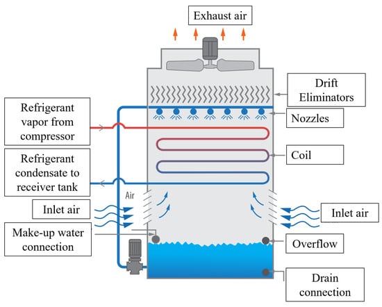
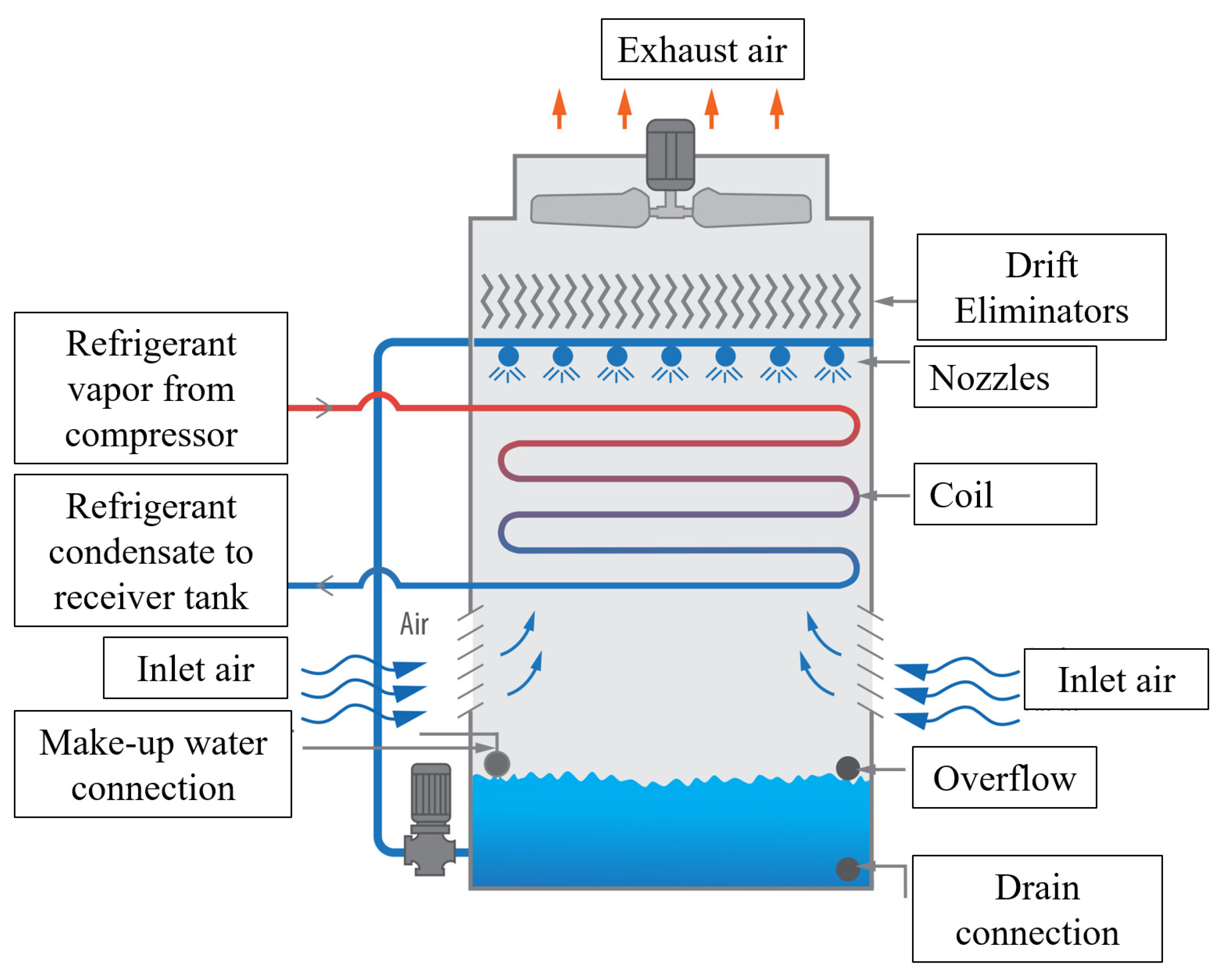
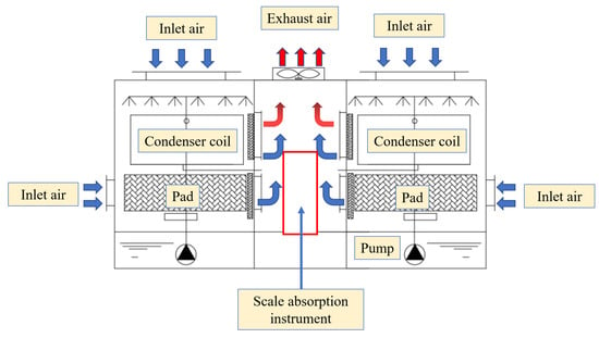
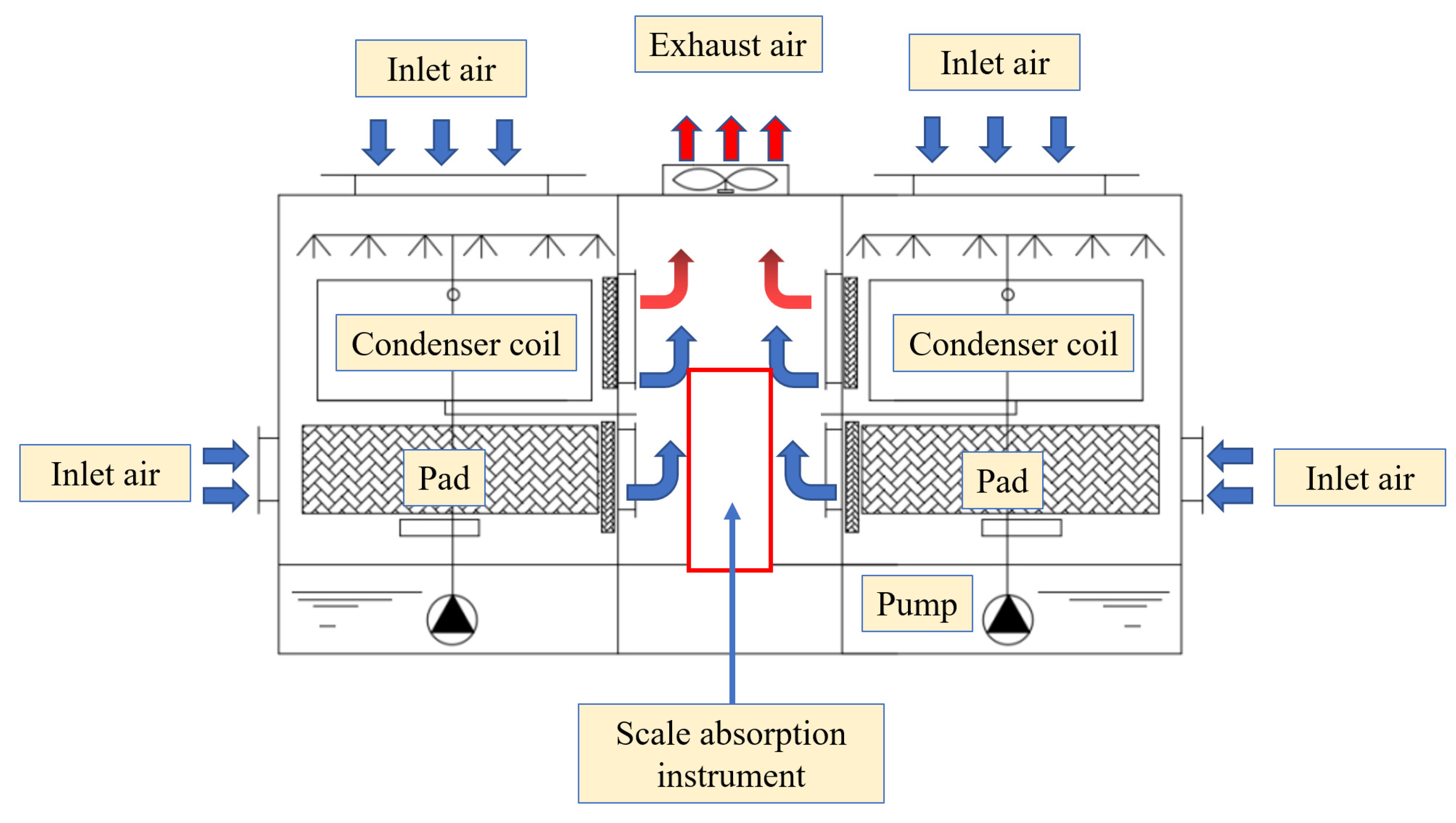
The evaporative condenser is a device that combines a cooling tower and condenser (sometimes it can also spray water directly on the surface of the condenser) and uses the evaporation of water to dissipate heat for the condenser. When the evaporative condenser is working, the water pump extracts cold water from the unit’s circulating water tank and sprays it onto the surface of the heat exchange coil through a nozzle, forming a uniform water film. Ambient air enters through the inlet of the evaporative condenser, and under the action of the exhaust fan, the inlet air is forced to sweep over the surface of the heat exchange coil. On the surface of the heat exchange coil, air and water exchange heat and mass under the combined action of temperature difference and water vapor pressure difference, thereby cooling the refrigerant inside the tube and causing the high-temperature and high-pressure refrigerant in the condenser to condense and dissipate heat. During the entire heat exchange process, the condensation heat is first transferred to the water film through sensible heat exchange, and then transferred to the cooling air through latent heat exchange. Finally, it is discharged into the ambient air through a fan [18]. Figure 1 is a schematic diagram of evaporative condensation technology.
Figure 1.
Schematic diagram of evaporative condensation technology.
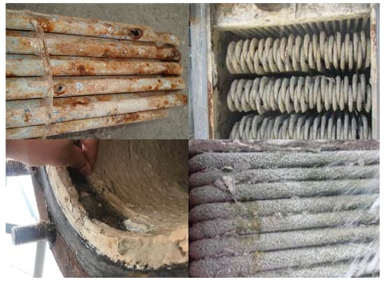
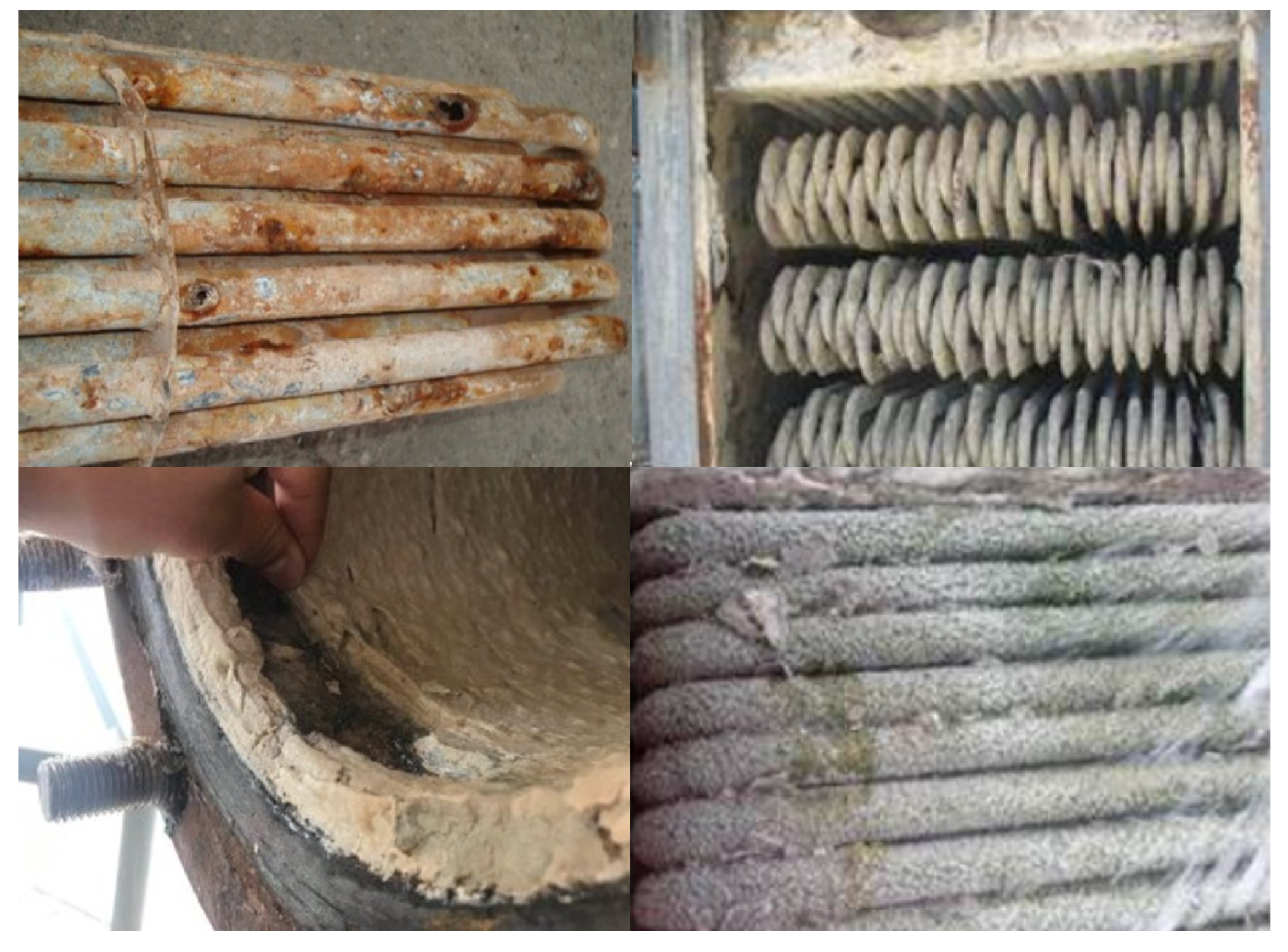
However, the practical application of evaporation condensation technology faces many challenges, the greatest of which is due to water on the condenser surface causing condenser surface scaling, which then causes the condensing efficiency to decline. Relevant data show that 1 mm thick scale on the heat exchanger surface reduces heat transfer efficiency equivalent to adding a 100 mm thick steel plate to the heat exchanger. Therefore, solving the problem of evaporative condenser scaling should not be delayed, as shown in Figure 2.
Figure 2.
Evaporative condenser with serious scaling problems in practical applications.
2.2. Self-Priming Technology
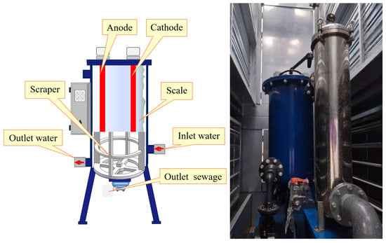
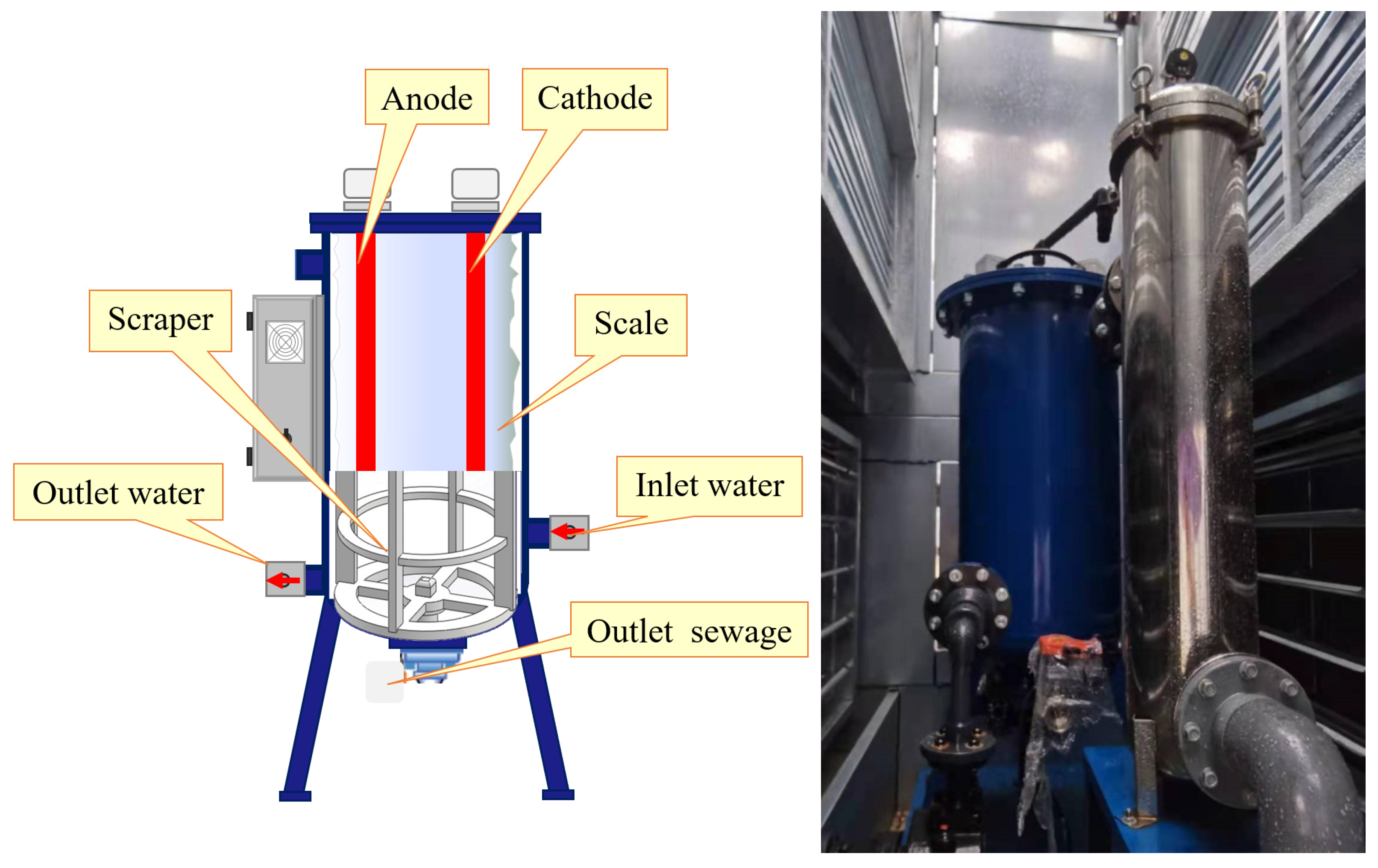
Self-priming scaling water treatment methods use a unique electrochemical process that can positively, efficiently, and economically solve the problems associated with hard water without the use of harmful chemicals. They are characterized by their green environmental protection, with no chemicals in or out, and have a significant effect on scaling and corrosion. One of the latest circulating water electrochemical comprehensive treatment systems (ECTs) is cooling tower circulating water treatment technology. ECT circulating water treatment system can prevent scaling, biological contamination, and microbial growth; inhibit corrosion; produce oxidants in the water to kill microorganisms; and prevent airborne bacteria. It works through a unique electrochemical process that is part of active pre-scaling technology: through electrolysis, scale-forming ions in the water are pre-precipitated on the cathode surface and removed. Figure 3 is a structural and physical diagram of the electrochemical scale absorber.
Figure 3.
Structure and object diagram of electrochemical scale absorber.
2.3. Self-Priming Scaling Scale Evaporative Condenser
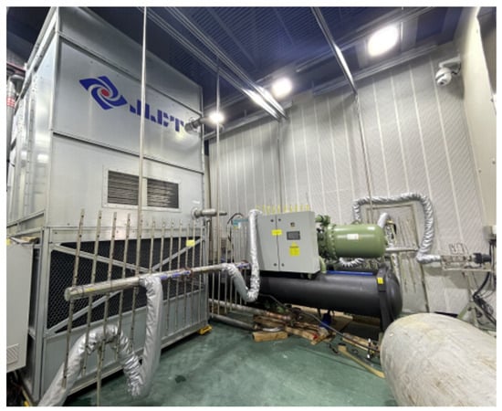
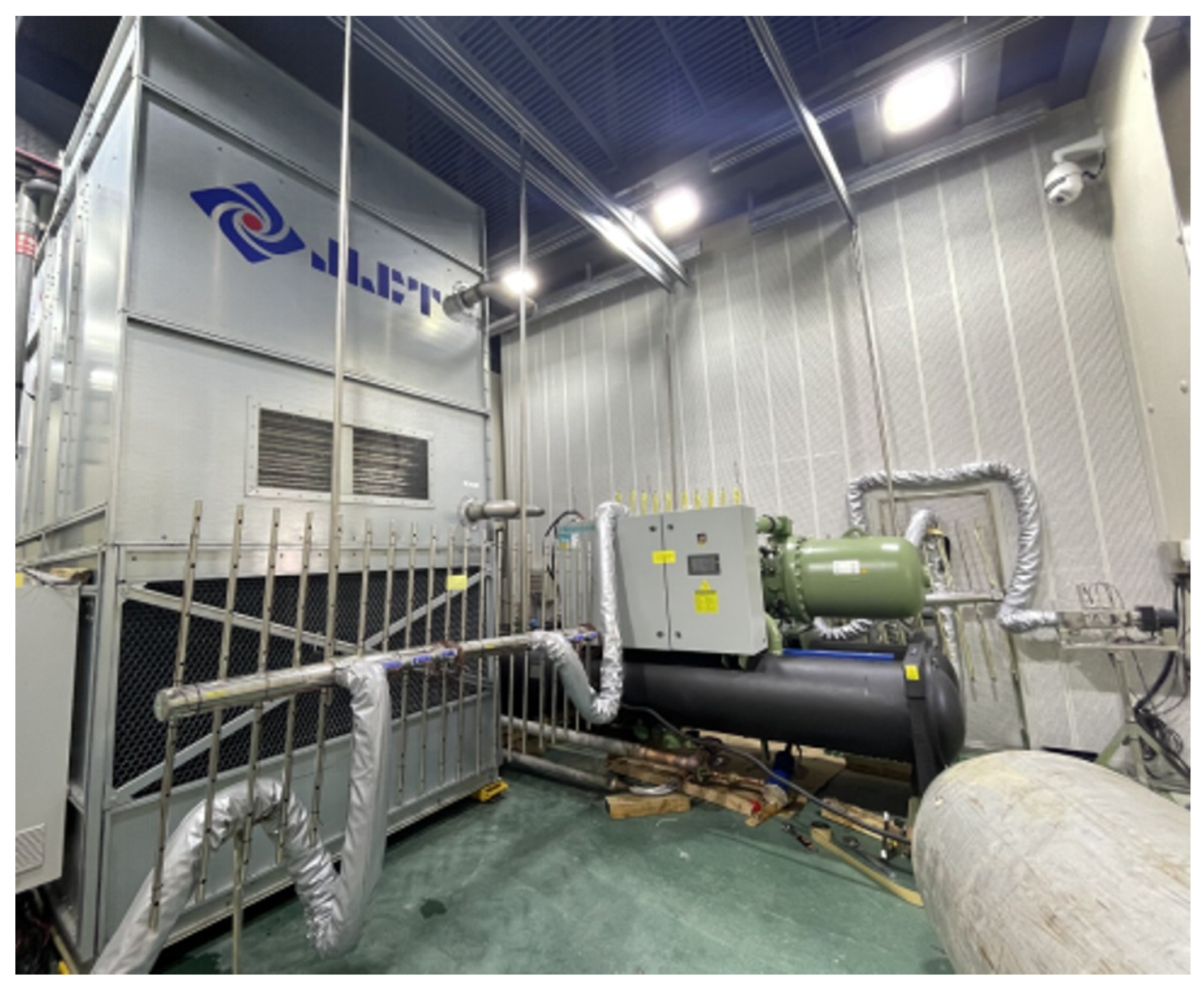
The proposed innovations are as follows: (1) building on the traditional evaporative condenser, the new type of self-priming scaling evaporative condenser with a built-in electrochemical scale absorber changes the traditional water quality treatment cycle method from “preventing scaling” to “scale absorption” to solve the problem of condensation efficiency decline of the evaporative condenser due to easy scaling; (2) integrating the water treatment device and evaporative condenser to increase system simplicity and save system space to facilitate user maintenance and management. When more than one evaporative condenser is used in combination, there can also be more than one evaporative condenser tank in parallel with a common electrochemical scale absorber, greatly reducing the equipment investment; (3) adopting a combination of downstream and cross-flow to enhance the thermal efficiency. At the same time, packing media is added to reduce the circulating spray water temperature and increase the heat dissipation effect. Figure 4 and Figure 5 show the model and physical drawings of the unit, respectively.
Figure 4.
Unit modeling diagram.
Figure 5.
Physical drawing of the unit.
3. Experimental Methods
3.1. Technical Parameters of the Equipment
The evaporative condenser’s condensate coil uses round steel tubes arranged in a positive triangle forked discharge placement. The evaporative condenser’s basic parameters are shown in Table 1; the basic parameters of the condensate coil are shown in Table 2.
Table 1.
Unit design parameters.
Table 2.
Condensation coil basic parameter.
3.2. Experimental System Introduction
In order to test the performance of this new evaporative condenser, a complete refrigeration system was built, and the equipment list of the experimental system is shown in Table 3.
Table 3.
Experimental system equipment list.
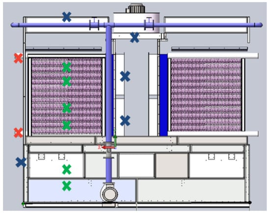
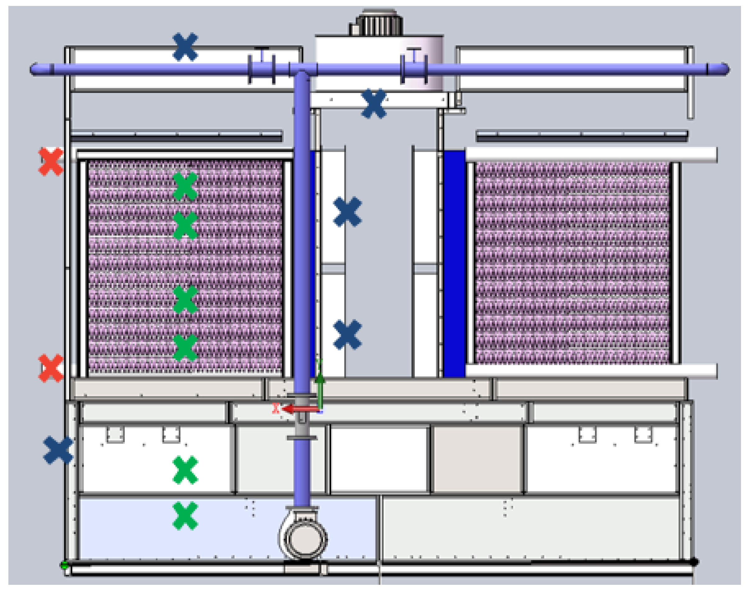
The measurement points in the air inlet, air outlet, circulating water tank, and scale absorber of the evaporative condenser are shown in Figure 6.
Figure 6.
Arrangement of measurement points in the evaporative condenser.
3.3. Experimental Step
The test site was located in the Enthalpy Difference Laboratory at the Shion Air Conditioning Plant in Zhuji City, Zhejiang Province, and the test period was from 29 May to 1 June 2021. The main contents of this test are as follows: (1) air parameters (wind speed, temperature, relative humidity); (2) refrigerant parameters (inlet and outlet pressures, inlet and outlet temperatures); (3) parameters related to sprinkler water (changes in water temperature); and (4) water quality test (including pH, TDS, conductivity, total alkalinity, total hardness, water temperature).
3.4. Evaluation Indicators
The new self-priming scaling evaporative condenser’s exhaust air volume under different fan frequencies for air intake is shown in Equation (1):
In the equation:
—Wind volume, m3/s;
—Head wind speed, m/s;
—Windward area, m2.
The calculation of the density of circulating water spray for the new self-priming scaling evaporative condenser at different pump frequencies is based on the real-time readings from the ultrasonic flow meter, which calculates the amount of sprayed water, as shown in Equation (2):
In the equation:
Γ—Spray water density, kg/(m−1·s−1);
—Spray water volume, kg/s;
—Number of tubes per layer;
—Heat transfer tube length, m.
The refrigeration capacity of the experimental system is calculated based on the change in chilled water temperature at the chilled water side of the evaporator, as shown in Equation (3):
In the equation:
—System cooling capacity, kW;
—Chilled water quality, kg;
—Specific heat of chilled water, J/(kg·K);
—Temperature difference of chilled water passing through the evaporator, °C.
According to the principle of refrigeration and the law of conservation of energy in a system, the actual heat rejection of the evaporative condenser for the system cooling capacity and the compressor power Pc sum are shown in Equation (4):
In the equation:
—Quantity of heat discharged, kW;
—Compressor power, kW.
From the condensing pressure measured in the experiment, the condensing temperature of this refrigeration system is calculated as shown in Equation (5).
In the equation:
—Condensing temperature, °C;
—Condensing pressure, Pa.
The energy efficiency ratio EER of the evaporative condenser is calculated as shown in Equation (6).
In the equation:
—Compressor power for refrigeration systems, kW;
—Pump power for refrigeration systems, kW;
—Fan power for refrigeration systems, kW.
The partial load performance factor IPLV is calculated based on EER as shown in Equation (7):
In the equation:
A—EER at 100% load;
B—EER at 75% load;
C—EER at 50% load;
D—EER at 25% load.
The power consumption ratio of the evaporative condenser is the ratio of the self-power of the evaporative condenser to the measured converted nominal heat rejection [19], as shown in Equation (8):
In the equation:
—Evaporative condenser power consumption ratio.
4. Discussion of Results
4.1. Air and Water Volume Testing
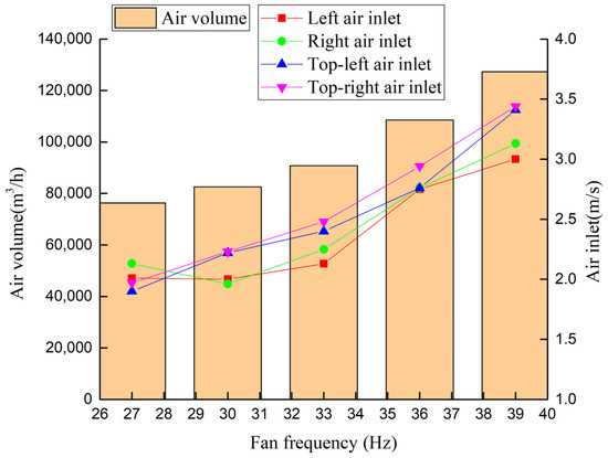
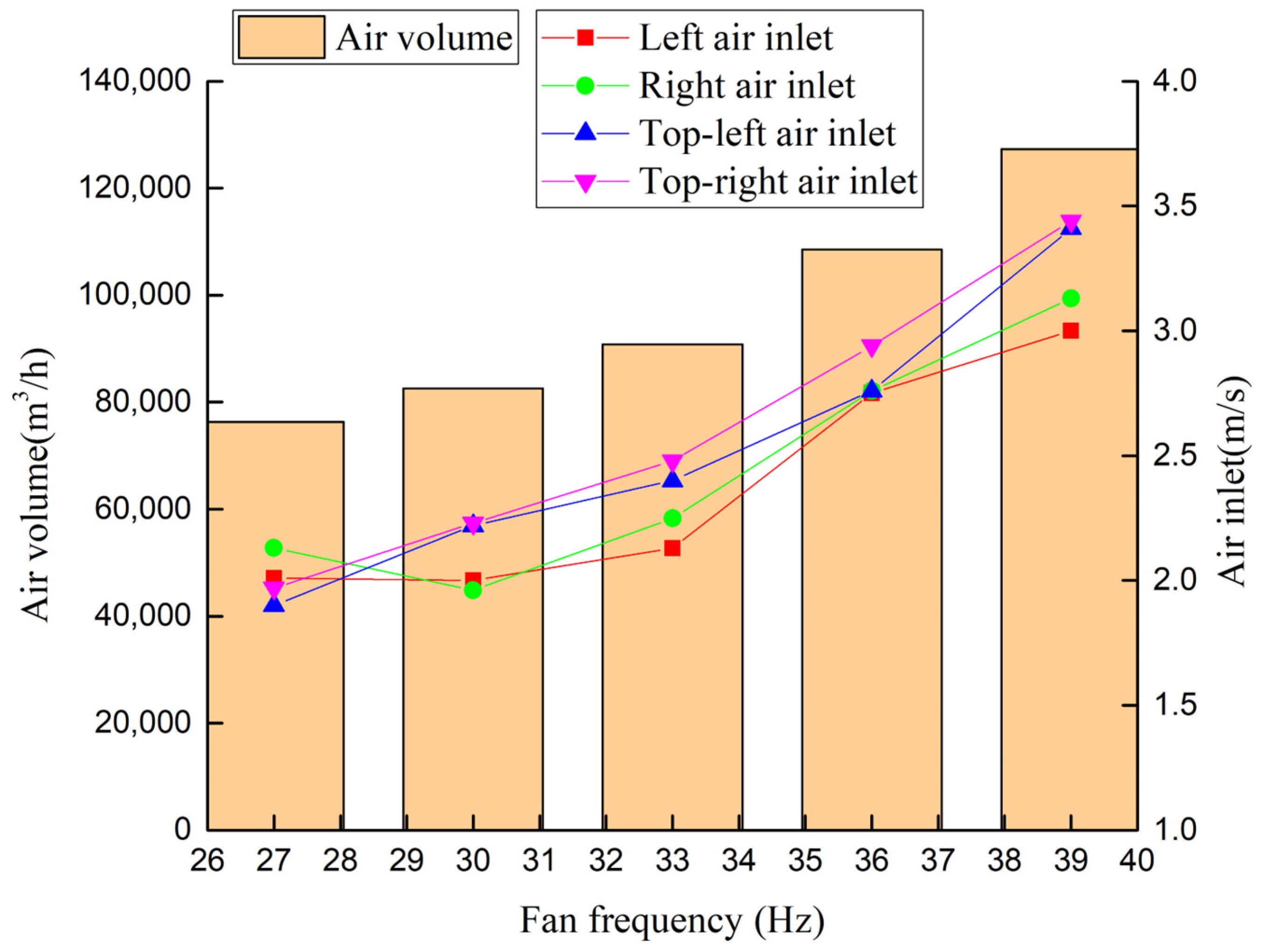
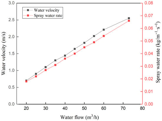
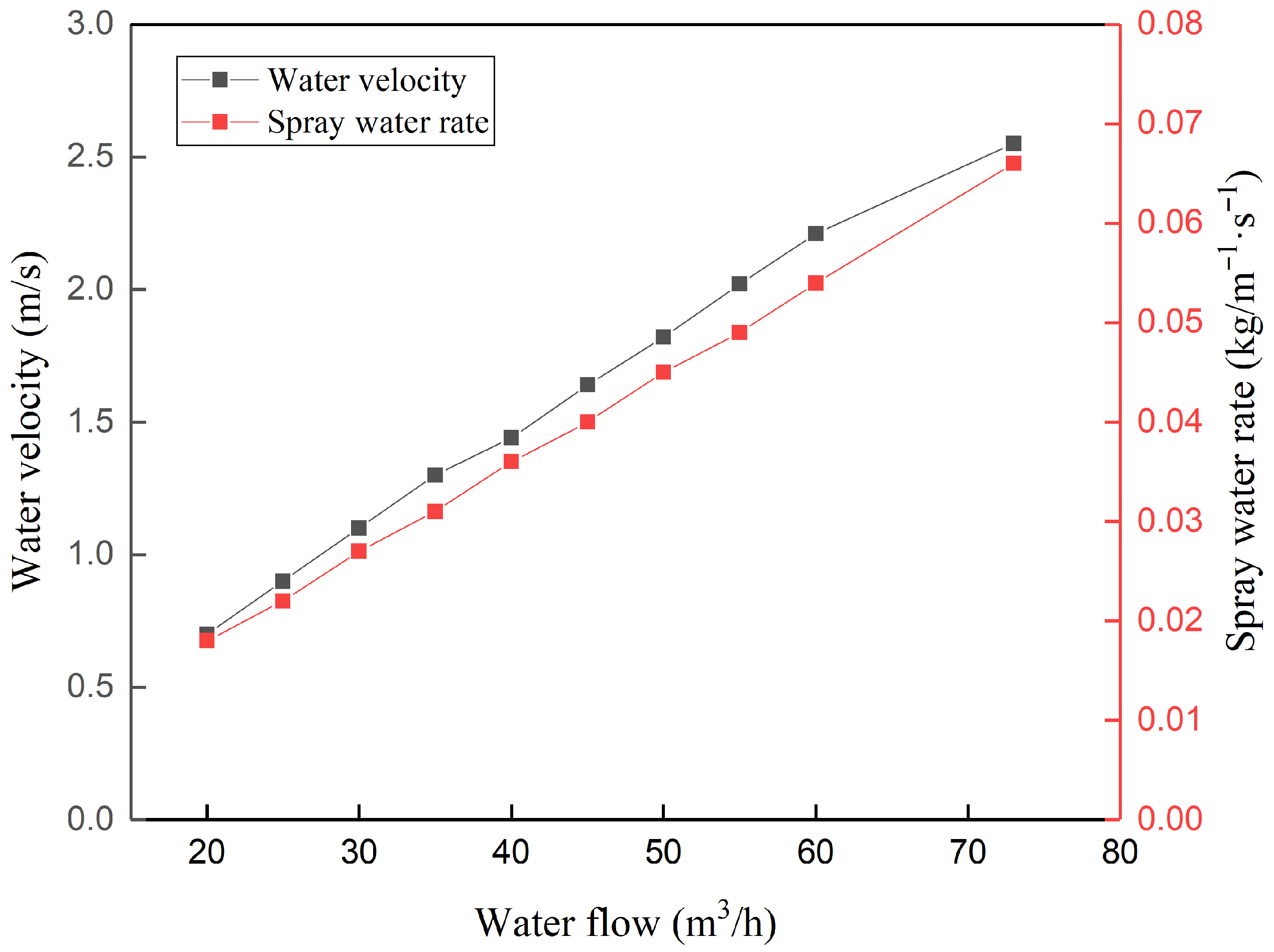
Under the design conditions (inlet air dry bulb temperature 31.2 °C, wet bulb temperature 25 °C) and fixed spray water volume for the design value, the air velocity of each air outlet was tested under different fan frequencies, and the air volume was calculated. Calculation results are shown in Table 4 below; Figure 7 and Figure 8 show their airflow test and drench density results, respectively.
Table 4.
Unit air opening area.
Figure 7.
Airflow test results.
Figure 8.
Drenching density results.
4.2. Exhaust Heat Analysis
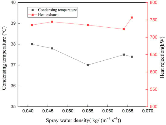
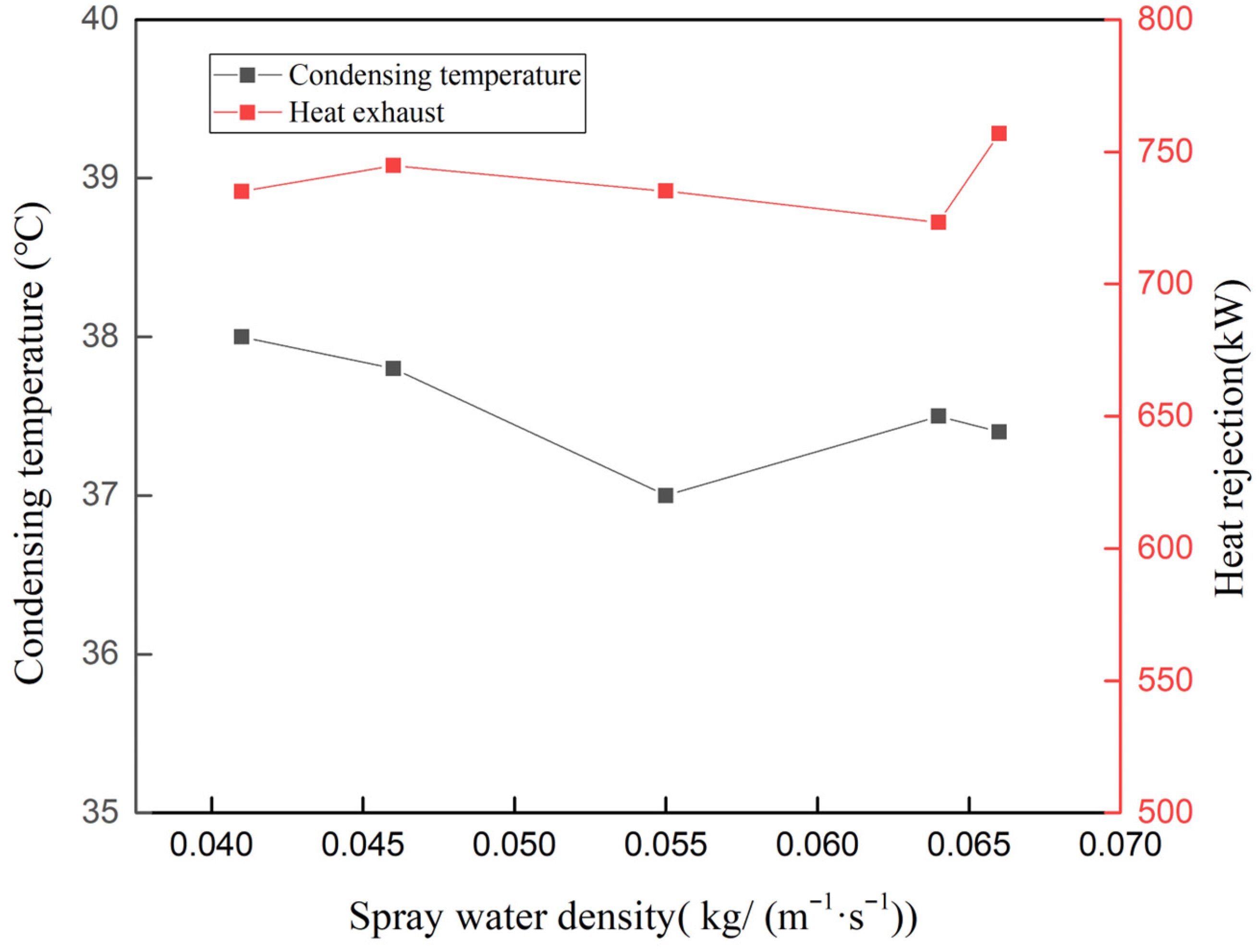
The relationship between spray density, condensation temperature, and heat rejection was analyzed, as shown in Figure 9. As spray density increased, condensation temperature first decreased and then increased, reaching its minimum at a spray density of 0.055 kg/m−1·s−1. With the increase in spray density, the evaporative condenser’s heat rejection first increased and then decreased; at a spray density of 0.046 kg/(m−1·s−1), the heat rejection reached 744.81 kW. Therefore, for the new self-priming scaling evaporative condenser, the spray density significantly impacts thermal performance. The spray density must reach a certain level to ensure that the entire outer surface of the heat exchanger coil is completely wetted by the spray water in order to achieve the best performance.
Figure 9.
Relationship between drench density, condensation temperature, and heat rejection.
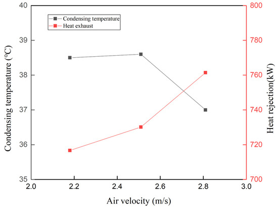
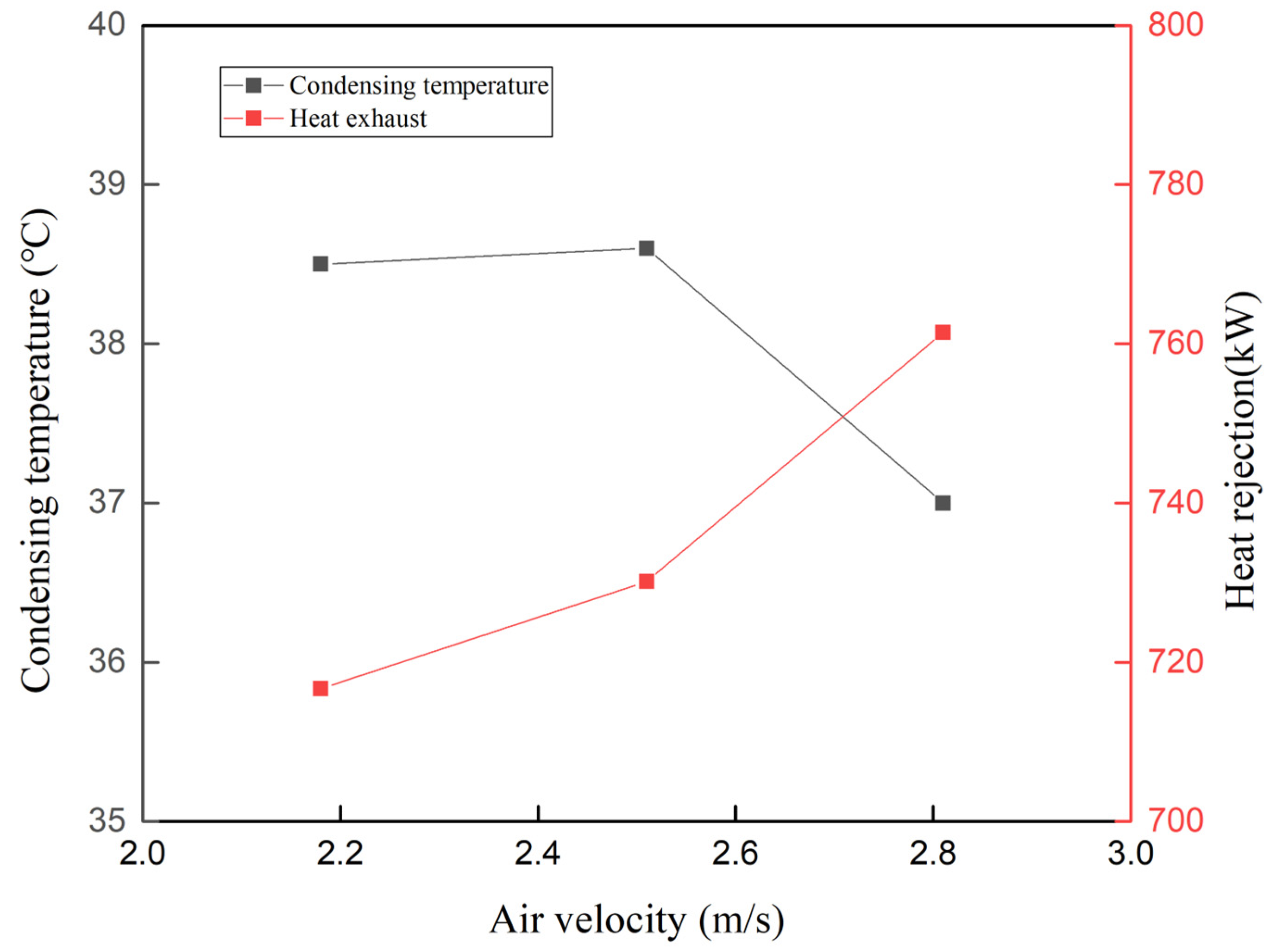
The relationship between inlet wind speed, condensing temperature, and heat rejection was analyzed, as shown in Figure 10. With the increase in head wind speed, condensing temperature decreased, reaching its lowest point at a head wind speed of 2.81 m/s. With the increase in head wind speed, the evaporative condenser’s heat rejection first increased and then decreased; due to limitations of the experimental conditions, we failed to perform experimental research on the head wind speed in smaller cases. In previous tests, the results indicated that the performance of the evaporative condenser was optimal when the wind speed was 2.9–3.1 m/s. The present experiment concluded that the heat rejection of the evaporative condenser increased when the wind speed increased. This experiment concludes that the unit performs best when the head wind speed is 2.81 m/s.
Figure 10.
Relationship between inlet air velocity, condensing temperature, and heat rejection.
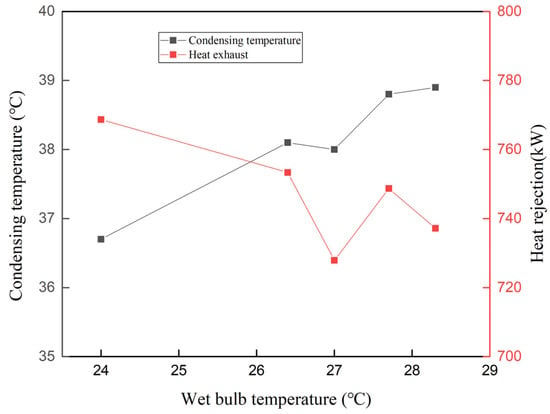
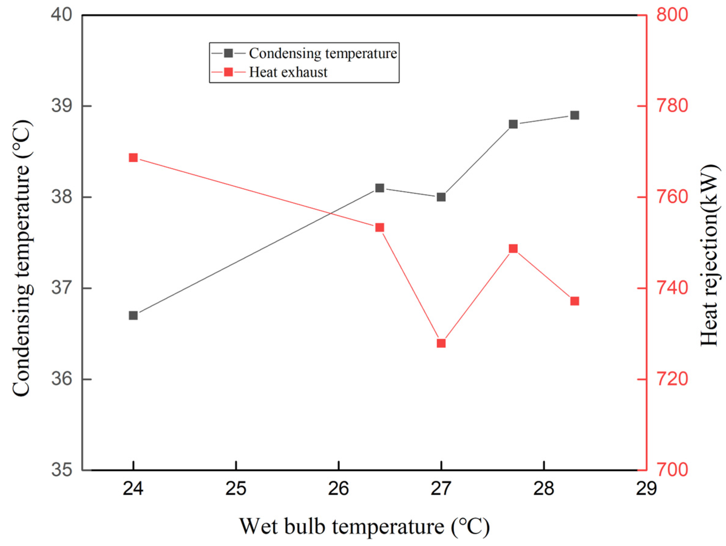
Next, we analyzed the relationship between the inlet air wet bulb temperature, condensing temperature, and heat rejection, as shown in Figure 11. With the increase in inlet air wet bulb temperature, condensing temperature gradually increased; the lower the inlet air wet bulb temperature, the lower the system condensing temperature. With the increase in inlet air wet bulb temperature, the evaporative condenser’s heat rejection gradually decreased; the lower the inlet air wet bulb temperature, the larger the unit heat rejection.
Figure 11.
Relationship between inlet air wet bulb temperature, condensing temperature, and heat rejection.
4.3. Part-Load Performance
The optimal combination of air velocity and water spray density was selected for the experiments, and the results of several experiments were synthesized to derive the performance changes of evaporative condensing air conditioning systems under different cooling load rates, as shown in Table 5 and Table 6.
Table 5.
Performance parameters of the unit under the optimal combination of head wind speed and spray density.
Table 6.
Unit performance parameters at different load rates.
After testing and calculation, the IPLV of the evaporative condensing unit is 3.29. According to the national standard GBT 18430.1 2007 “Vapor Compression Cycle Chilled Water (Heat Pump) Unit Part 1: Chilled Water (Heat Pump) Units for Industrial or Commercial Use and Similar Purposes” [20], the performance coefficient of the integrated part of the evaporative condenser system should be greater than or equal to 3.2. The consumptive electric power ratio is 0.018, which is lower than the recommended value of 0.022 in the relevant standards, proving that the unit is reasonably designed with excellent performance.
4.4. Water Quality Testing
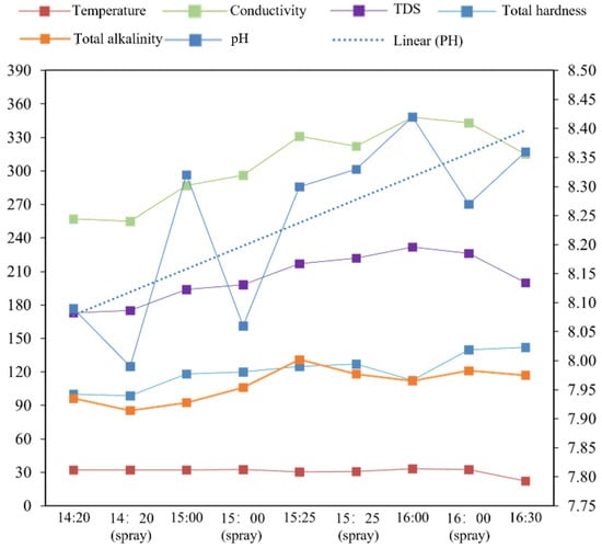
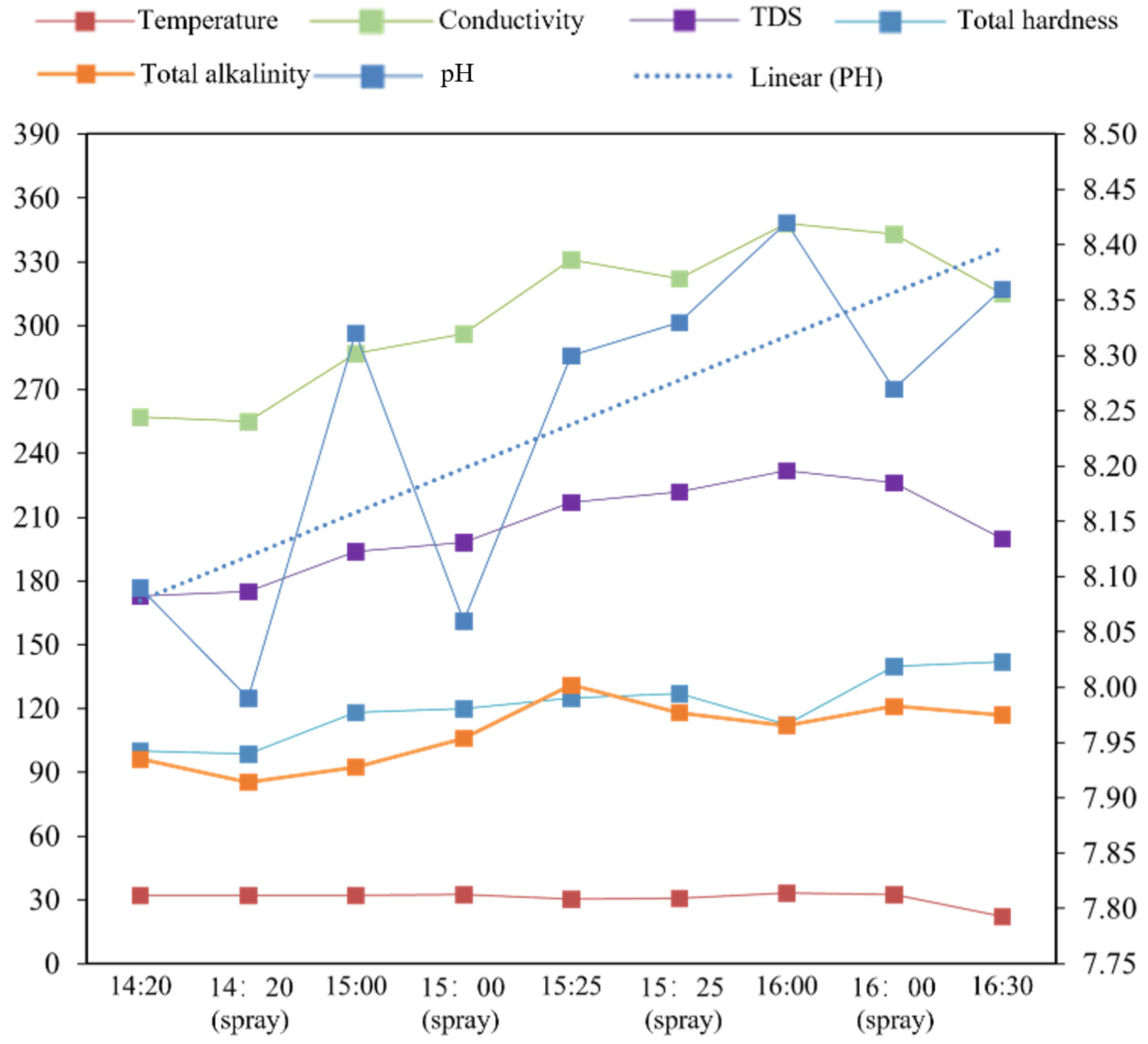
The new self-priming scaling evaporative condensing unit was tested without any water treatment device. The unit was stabilized and then operated continuously for 100 min (from 14:20 to 16:00), as shown in Figure 12. The pH, conductivity, TDS, total hardness, and total alkalinity of the circulating water in the water tank all increased over time. The numerical value of the total hardness concentration was multiplied by 1.4, the average (conductivity, TDS, total hardness, total hardness) concentration was multiplied by 1.4, and the average (conductivity, TDS, total hardness, total alkalinity) concentration was multiplied by 1.34.
Figure 12.
ECT electrochemical scale absorber without water quality changes.
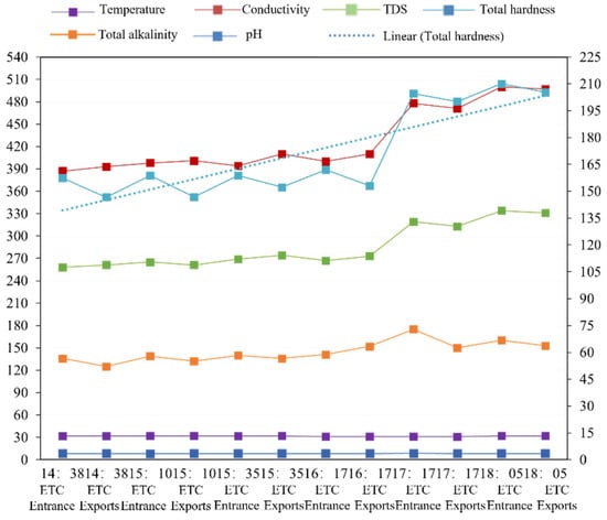
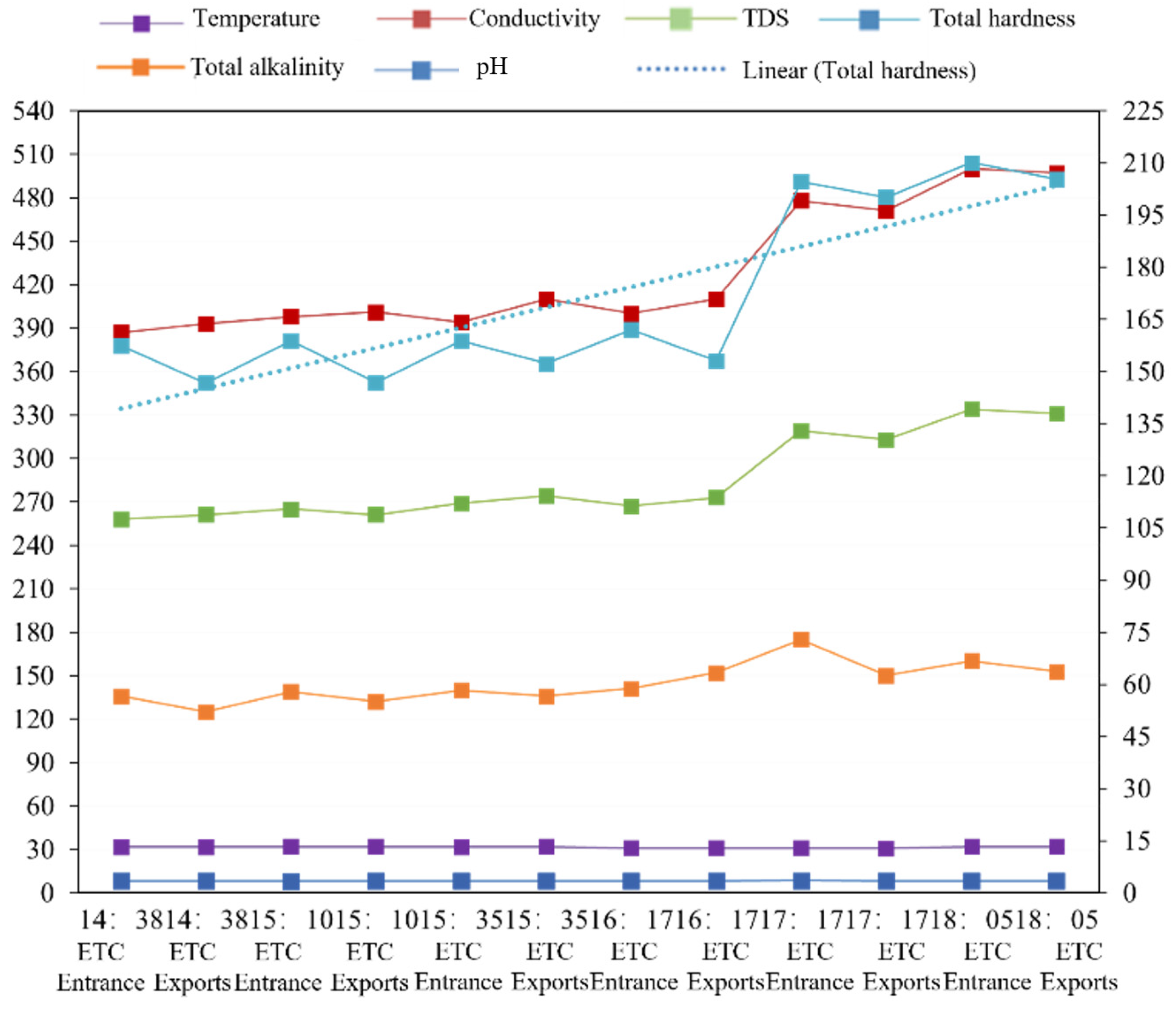
The new self-priming scaling evaporative condensing unit was tested with circulating water treated by the ECT electrochemical scale absorber (10 tons per hour). After stabilization, the unit and water treatment equipment were operated continuously for 207 min (from 14:38 to 18:05), as shown in Figure 13. The pH, conductivity, TDS, total hardness, and total alkalinity of the circulating water increased over time. The total hardness concentration was multiplied by 1.3, and the average (conductivity, TDS, total hardness, total alkalinity) concentration was multiplied by 1.24.
Figure 13.
ECT electrochemical scale absorber with water quality changes.
A comparison of the unit with the ECT electrochemical instrument on and off shows that when the instrument is on, the running time is twice as long as when closed, and the average concentration is multiplied by 1.24 instead of 1.34. Thus, it can be concluded that, when turned on, the ECT electrochemical instrument can effectively reduce the concentration of water quality parameters; for example, the rate of increase in total hardness per minute decreases from 0.4 mg/L to 0.23 mg/L, a reduction of 42.5%. The electrochemical meter effectively reduces the increase of total hardness and reduces the occurrence of scaling in the unit.
5. Conclusions
- (1)
- Under different working conditions, the condensing temperature of the new self-priming scaling evaporative condenser ranges from 36.7 to 38.9 °C, and the heat rejection ranges from 716.69 to 768.66 kW. The condensing temperature under different load rates ranges from 22.7 to 36.7 °C. The IPLV of the evaporative condenser unit is 3.29, and the performance coefficient of the integrated part of the evaporative condenser system should be equal to or greater than 3.2.
- (2)
- The IPLV of the evaporative condensing unit is 3.29, and the performance coefficient of the integrated part of the evaporative condenser system should be greater than or equal to 3.2. The power consumption ratio (consumptive electric power ratio) is 0.018, which is lower than the recommended value of 0.022 of the relevant standards, and the unit has a good overall performance.
- (3)
- In terms of water quality treatment, the use of the ECT electrochemical instrument can effectively reduce the concentration multiplier of water quality; for example, the rate of increase in total hardness per minute decreases from 0.4 mg/L to 0.23 mg/L, a reduction of 42.5%. Turning on the electrochemical instrument effectively reduces the increase in total hardness and reduces the occurrence of scaling in the unit.
Author Contributions
Conceptualization, J.C. and X.H.; methodology, X.H.; software, N.X.; validation, Z.P., X.H. and G.D.; formal analysis, J.T.; resources, R.H.; data curation, J.C.; writing—original draft preparation, J.C.; writing—review and editing, G.D.; project administration, N.X.; funding acquisition, Z.P. All authors have read and agreed to the published version of the manuscript.
Funding
This research was funded by (1) Science and Technology Projects of Xizang Autonomous Region, China Research on Key Technologies, Equipment, and Standard Systems for Low-Carbon Buildings under the Unique Climatic Resource Characteristics of Tibet (Grant No. XZ202401ZY0109); (2) the Opening Funds of the State Key Laboratory of Building Safety and Built Environment (Grant No. BSBE-EET2024-04); (3) the Key Project of the Scientific Research Plan of Shaanxi Provincial Department of Education (No. 24JR069); (4) the Xizang Autonomous Region Technological Innovation Guidance Plan Project: Research and Application of Key Technologies for Intelligent Computing Integration (No. XZ202501JX0005).
Data Availability Statement
The data presented in this study are available on request from the corresponding authors.
Conflicts of Interest
Author Rentu He is employed by Zhejiang Jinling Refrigeration Engineering Co., Ltd. The authors declare that the research was conducted in the absence of any commercial or financial relationships that could be construed as a potential conflict of interest.
References
- Sun, H.; Chen, C.; Zhang, G. Survey and research on the current situation of operation and management of air conditioning systems in large public buildings in China. Build. Energy Conserv. 2020, 48, 8–13. [Google Scholar]
- Shang, R.; Lu, C.; Hui, X.; Wang, L.; Chen, D.; Geng, J. Research on the mechanism and path of industrial Internet to help realize the goal of “double carbon”. New Ind. 2024, 14, 33–42+50. [Google Scholar]
- Xiao, X. Progress in the application of wind wall technology in data centers. Refrig. Air Cond. 2023, 23, 1–9. [Google Scholar]
- Chu, J.; Huang, X. Research status and development trends of evaporative cooling air-conditioning technology in data centers. Energy Built Environ. 2021, 4, 86–110. [Google Scholar] [CrossRef] [Scilit]
- Data Center Cooling Working Group of the China Institute of Refrigeration. Annual Development Research Report on Data Center Cooling Technology in China, 2022; China Construction Industry Press: Beijing, China, 2022; pp. 9–10. [Google Scholar]
- Chuklin, S.G.; Yanovskiy, Y.L. Heat transfer in a plate-type evaporative condenser. Heat Transf.-Res. 1975, 7, 79–84. [Google Scholar]
- Fisher, U.; Leidenfrost, W.; Li, J.S. Hybrid Evaporative Condenser Cooling Tower. Heat Transf. Eng. 1983, 4, 28–41. [Google Scholar] [CrossRef] [Scilit]
- Erens, P.J. Comparison of Some Design Choices for Evaporative Cooler Cores. Heat Transf. Eng. 1988, 9, 29–35. [Google Scholar] [CrossRef] [Scilit]
- Halasz, B. A general mathematical model of evaporative cooling devices. Rev. Oenerale Therm. 1998, 37, 245–255. [Google Scholar] [CrossRef] [Scilit]
- Wittek, U.; Meiswinkel, R. Uon-linear behaviour of RC cooling towers and its effects on the structural design. Eng. Struct. 1998, 20, 890–898. [Google Scholar]
- Lucas, E.M.; Randall, J.M.; Meneses, J.F. Potential for evaporative cooling during heat stress periods in pig production in Protugal. J. Agric. Engng. Res. 2000, 76, 363–371. [Google Scholar] [CrossRef] [Scilit]
- Krishan, K.; Ashvini, K.; Mullick, S.C. Space conditioning using evaporative cooling for summers in Delhi. Build. Environ. 2001, 36, 15–25. [Google Scholar] [CrossRef] [Scilit]
- Manske, K.A.; Reindl, D.T.; Klein, S.A. Evaporative condenser control in industrial refrigeration systems. Int. J. Refrig. 2001, 21, 676–691. [Google Scholar] [CrossRef] [Scilit]
- Kim, H.-Y.; Kang, B.H. Effects of hydrophilic surface treatment on evaporation heat transfer at the outside wall of horizontal tubes. Appl. Therm. Eng. 2003, 23, 449–458. [Google Scholar] [CrossRef] [Scilit]
- Islam, M.R.; Jahangeer, K.A.; Chua, K.J. Experimental and numerical study of an evaporatively cooled condenser of air-conditioning systems. Energy 2015, 87, 390–399. [Google Scholar] [CrossRef] [Scilit]
- Fiorentino, M.; Starace, G. The design of counter current evaporative condensers with the hybrid method. Appl. Therm. Eng. 2018, 130, 889–898. [Google Scholar] [CrossRef] [Scilit]
- Khan, A.; Bradshaw, C.R. Quantitative comparison of the performance of vapor compression cycles with compressor vapor or liquid injection. Int. J. Refrig. 2023, 154, 386–394. [Google Scholar] [CrossRef] [Scilit]
- Chu, J.; Xu, W.; Huang, X.; Geng, Z.; Xuan, J. Study on optimization of indirect-direct evaporative chiller for producing cold water in hot and dry areas. Renew. Energy 2022, 181, 898–913. [Google Scholar] [CrossRef] [Scilit]
- T/CGMA 101002-2019; Evaporative Condenser. China General Machinery Industry Association: Beijing, China, 2019.
- GB/T 18430.1-2007; Vapor Compression Cycle Chilled Water (Heat Pump) Units Part 1: Chilled Water (Heat Pump) Units for Industrial or Commercial Use and Similar Applications. General Administration of Quality Supervision, Inspection and Quarantine of the People’s Republic of China: Beijing, China; Standardization Administration of China: Beijing, China, 2007.

Disclaimer/Publisher’s Note: The statements, opinions and data contained in all publications are solely those of the individual author(s) and contributor(s) and not of MDPI and/or the editor(s). MDPI and/or the editor(s) disclaim responsibility for any injury to people or property resulting from any ideas, methods, instructions or products referred to in the content. |
© 2025 by the authors. Licensee MDPI, Basel, Switzerland. This article is an open access article distributed under the terms and conditions of the Creative Commons Attribution (CC BY) license.