


Abstract
To investigate the energy loss characteristics of magnetic pumps, an experimental setup for magnetic transmission in pumps was constructed. Through experiments, the impact of various factors on the eddy current loss of the magnetic coupling was examined, including rotational speed, electrical conductivity of the isolation sleeve material, axial coupling length of the magnetic coupling, and the physical properties of the fluid medium. Additionally, the temperature variation at different axial positions along the isolation sleeve was measured. The results indicated that eddy current loss increases with higher rotational speeds and shows a nearly linear relationship with the axial coupling length of the magnetic coupling. Furthermore, as the conductivity of the isolation sleeve material rises, the eddy current loss also increases linearly. The conductivity and viscosity of the fluid medium were found to have negligible effects on eddy current loss. Friction losses due to the liquid medium inside the metal isolation sleeve were much smaller than the eddy current losses generated by the sleeve, and thus can be ignored. For non-metallic isolation sleeves, the energy loss is primarily attributed to fluid friction. Finally, the temperature along the axial direction of the isolation sleeve increases progressively from the flange to the bottom.
1. Introduction
Magnetic pumps are widely used for liquid transportation in industries such as petroleum, chemical, aerospace, etc. They have the advantage of no shaft seal leakage and are safer and more reliable than conventional centrifugal pumps. The main characteristics of magnetic couplings for pumps are the following: the magnetic rotor is a cylindrical structure with internal and external distribution; the inner magnetic rotor and the outer magnetic rotor operate synchronously with an isolation sleeve between them; the inner magnetic rotor is immersed in the fluid medium inside the isolation sleeve, which is a “wet” type. Relatively speaking, a magnetic coupling without an isolation sleeve can be referred to as a “dry” type.
The magnetic coupling of a magnetic pump often experiences severe heating of the metal isolation sleeve, deviation of magnetic torque from the design value, low efficiency and stability of magnetic drive, and even problems such as internal and external magnetic rotor slippage. With the promotion and application of high-speed magnetic drive pumps in key fields such as aviation and aerospace, any failure of permanent magnet couplings used in pumps can have catastrophic consequences. Therefore, it is urgent to conduct research on these issues.
In recent years, many scholars have carried out a great deal of research on magnetic coupling by means of empirical coefficient methods, theoretical analysis, experimental research and numerical calculation methods, mainly focusing on the following aspects: structural design of magnetic coupling [1,2,3,4], magnetic field analysis and transmission performance study [5,6,7], eddy current loss and transmission performance of magnetic pump isolation sleeve and multi-field coupling analysis of magnetic coupling [8,9,10]. Ziolkowski [11] combined theoretical analysis and experimental study to prove that there is drag force and repulsion force in the process of vortex-magnetic coupling transmission, and compared and analyzed the finite element simulation results and practical data, indicating that the quasi-static finite element method has the highest accuracy in three-dimensional finite element calculation. Li Bingfan [12] established a mathematical model of the magnetic coupling transmission process to solve the problem of torque transmission lag in a magnetic coupling rheological testing system. This model was developed on the basis of torque balance in a magnetic coupling rotatory rheometer test system, which considered friction loss for the jewel bearing, as well as the inertia of both the motor and fixture. Thierry Lubin [13] established a two-dimensional magnetic field model for permanent magnet couplings. In addition, the influence of magnetic air gap and pole pairs on output torque and axial force was studied. The parameters of the two-dimensional model were compared and modified by using the COMSOL finite element method. An experimental platform was set up to verify the theoretical analysis results, which confirmed the rationality of the theoretical model. Jiang [14] studied electromagnetic losses such as copper loss, iron loss and magnetic eddy current loss by using the two-dimensional transient finite element method, calculated electromagnetic power loss as the main source of heat flow field, and made a new evaluation of material performance according to temperature distribution. Chen [15] proposed an electromagnetic–thermal coupling method combining a thermal network model and the finite element method to study a doubly salient permanent magnet double-rotor motor; the finite element analysis method, testing and so on of the system were analyzed and compared. Zhang [16] divided the model into different temperature calculation segments by the finite element method, which predicted the electromagnetic heat distribution more quickly and with similar accuracy compared to the traditional synchronous magnetocaloric field coupling finite element analysis method. Gang-Hyeon Jang [17] and his team put forward a permanent magnet coupling with Halbach array configuration, and conducted detailed comparative analysis and research with the traditional axial flux permanent magnet coupling. The research results show that the permanent magnet coupling adopting Halbach array configuration performs better in terms of magnetic energy efficiency, and has higher efficiency than the traditional design. Hyeon-Jae Shin et al. [18] put forward a prototype of a double-layer permanent magnet eddy current magnetic coupling drive and built an experimental device. Through finite element analysis and experimental research, the thickness of the permanent magnet, magnetic air gap, and the influence of yoke thickness and other structural parameters on transmission torque were examined. In order to improve the output performance of a high-voltage electric energy harvester by optimizing the magnetic field conditions, Liu, Lei et al. [19] conducted a detailed study on the influence of the number and arrangement of magnets on the output performance.
When the inner magnetic rotor of a magnetic pump rotates in the liquid medium, it is simultaneously subjected to the dual effects of flow field and magnetic field, which jointly affect the efficiency and stability performance of the inner magnetic rotor. To examine pump magnetic coupling, Ravaud et al. [20] comparatively analyzed the magnitude of torque in three magnetizing directions: radial, axial, tangential. A new expression for torque was proposed and a magnetic field model was established to analyze the magnetic field distribution in the air gap; the authors established the magnetic field distribution and built a finite element model to calculate the eddy current loss of the magnetic coupling for pumps. In order to solve the problem of demagnetization in high-temperature magnetic drive pumps, Yuan et al. [21] used Ansoft Maxwell analysis software to numerically simulate the new magnetic drive pump drive device through the electromagnetic coupling method, and focused on analyzing some influencing factors of magnetic torque. An [22] developed a new permanent magnet axial thrust balance structure and numerically calculated and experimentally verified the magnetic force and fluid thrust of a magnetically driven pump using Ansoft software. Cristian [23] investigated the finite element model of a magnetically induced pump and simulated its transient magnetic field. Wang [24] used the magnetic torque and the magnetic vortex loss as the judging index, using Ansoft-Maxwell software to numerically calculate the magnetic rotor model, and investigated the effects of pole pairs and magnet gap on the transmission performance of the magnetic coupling.
In summary, previous studies have conducted extensive analysis and experimental research on the structural design, magnetic field analysis, and transmission performance of magnetic couplings, mostly focusing on “dry” magnetic couplings. In terms of “wet” magnetic couplings for pumps, simulation analysis and theoretical research have mainly been conducted, and there is still a lack of sufficient experimental research on the impact of different influencing factors on energy loss. In addition, studies have shown that the flow field and magnetic field interact with each other [25], and it is worth exploring whether the conductivity and viscosity of the flowing medium have an impact on eddy current losses. This paper will conduct experimental research on the above issues.
2. Theory Related to Energy Loss of Magnetic Pump Coupling
2.1. Isolation Sleeve Eddy Current Loss
When the magnetic coupling used for pumping is running normally, the inner magnetic steel and the outer magnetic steel rotate synchronously at a certain angle. At this time, the isolation sleeve is in an alternating magnetic field, and the magnitude and direction of the magnetic field change according to a certain law, causing the magnetic flux in the isolation sleeve to change over time. Due to the fact that the material of the isolation sleeve is generally metal, the isolation sleeve will generate eddy currents, which not only reduces the magnitude of the magnetic field of magnetic coupling, but also reduces the transmission efficiency of magnetic torque. At the same time, part of the energy is released in the form of heat due to the eddy current, which reduces the efficiency of the unit. The heat generated by the eddy current increases the temperature of the permanent magnet and reduces the magnetic performance of the permanent magnet. When the temperature rises to a certain extent, the phenomenon of high temperature demagnetization may even occur. Accurate calculation of eddy current loss of magnetic coupling can effectively estimate the efficiency of the machine and indicate reasonable power combinations, which have important reference value for optimizing the design of magnetic coupling. The eddy current loss is usually calculated by the eddy current reaction torque formula [26], magnetic permeability eddy current formula [27] and Maxwell equation derivation formula [28]. The reverse torque generated by eddy currents can be calculated from the solved maximum static magnetic torque formula, as shown in Equation (1).
where Tw is the vortex counter torque, N·m; Tmax is the maximum static magnetic torque, N·m; n is the rated speed of magnetic coupling, r/min; r is the average radius of the isolation sleeve, m; tb is the wall thickness of the isolating sleeve, m; ξ is the resistivity of the isolating sleeve, Ω·m.
The formula of magnetic permeability eddy current is shown in Formula (2).
where r3 is the inner diameter of the isolating sleeve, m; lx is the axial magnetization length of the isolation sleeve, m; ηx is magnetic susceptibility; ξ is the resistivity of the isolating sleeve, Ω·m; tb is the wall thickness of the isolating sleeve, m; f is the working frequency of the magnetic pole, Hz; B0 is the magnetic induction intensity acting on the isolation sleeve, Gs, 1 Gs = 10−4 T. According to the eddy current formula of magnetic permeability, the eddy current loss of the magnetic coupling is related to the thickness of the isolation sleeve, the material of the isolation sleeve, the overall dimensions and the rotation speed of the isolation sleeve, and the strength of the magnetic field.
The formula for the derivation of Maxwell’s equation is given in Equation (3).
where n is the rotation speed of the motor, r/min; σ is conductivity, S/m; σcy is current density, A/m2; l is the magnetization length, m; tb is the wall thickness of the isolating sleeve, m; r3 is the inner diameter of the isolating sleeve, m; B0 is the magnetic induction intensity acting on the isolating sleeve, T. The derivation formula of Maxwell’s equation is one of the widely used formulas at present.
2.2. Friction Loss Between Internal Magnetic Steel and Liquid Medium
In addition to eddy current losses, the high-speed rotation of the inner magnetic rotor generates a tangential force on the circumferential surface of the rotor due to the viscous effect of the fluid, which hinders its rotation in the opposite direction, resulting in frictional losses between the inner magnetic steel and the liquid medium.
This friction loss consists of two parts: the column surface friction loss between the inner magnetic rotor and the cooling medium (cylindrical surface friction loss); and the end surface friction loss between the inner magnetic rotor and the cooling medium (disk loss) [29]. The friction loss of the cylindrical surface is calculated by Equation (4).
where cf is the coefficient of frictional resistance (cf is related to the viscosity, pressure, flow state of the medium and the roughness of the cylindrical surface); ρ is density of liquid medium, kg/m3; ω is the angular velocity of the internal magnetic steel, rad/s; r1o is the outer diameter of the inner magnetic steel, m; L is the axial length of the magnetic coupling, m; g is the acceleration of gravity. The disc loss is calculated by Equation (5).
where cτ is the coefficient of frictional resistance; ρ is the density of the liquid medium, kg/m3; ω is the angular velocity of the internal magnetic steel, rad/s; r1o is the outer diameter of the inner magnetic steel, m. Therefore, the friction loss between the inner magnetic steel and the liquid medium is shown in Formula (6).
According to Equations (4) and (5), the cylindrical friction loss is proportional to the fourth power of the sleeve radius and the axial length of the magnetic coupler, while the disk friction loss is proportional to the fifth power of the sleeve outer diameter. Reasonable design of the length-to-diameter ratio of the magnetic coupler can effectively reduce the total friction loss between the inner magnet and the liquid medium. According to the simulation analysis and theoretical calculation by the project team members, the friction loss and other losses between the inner magnet and the liquid medium are smaller than the eddy current loss and can be neglected. The energy loss measured in the test is mainly the eddy current loss of the isolation sleeve, which is also verified by the following experimental study.
3. Experimental Device for Transmission Performance of Magnetic Coupling for Pumps
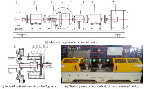
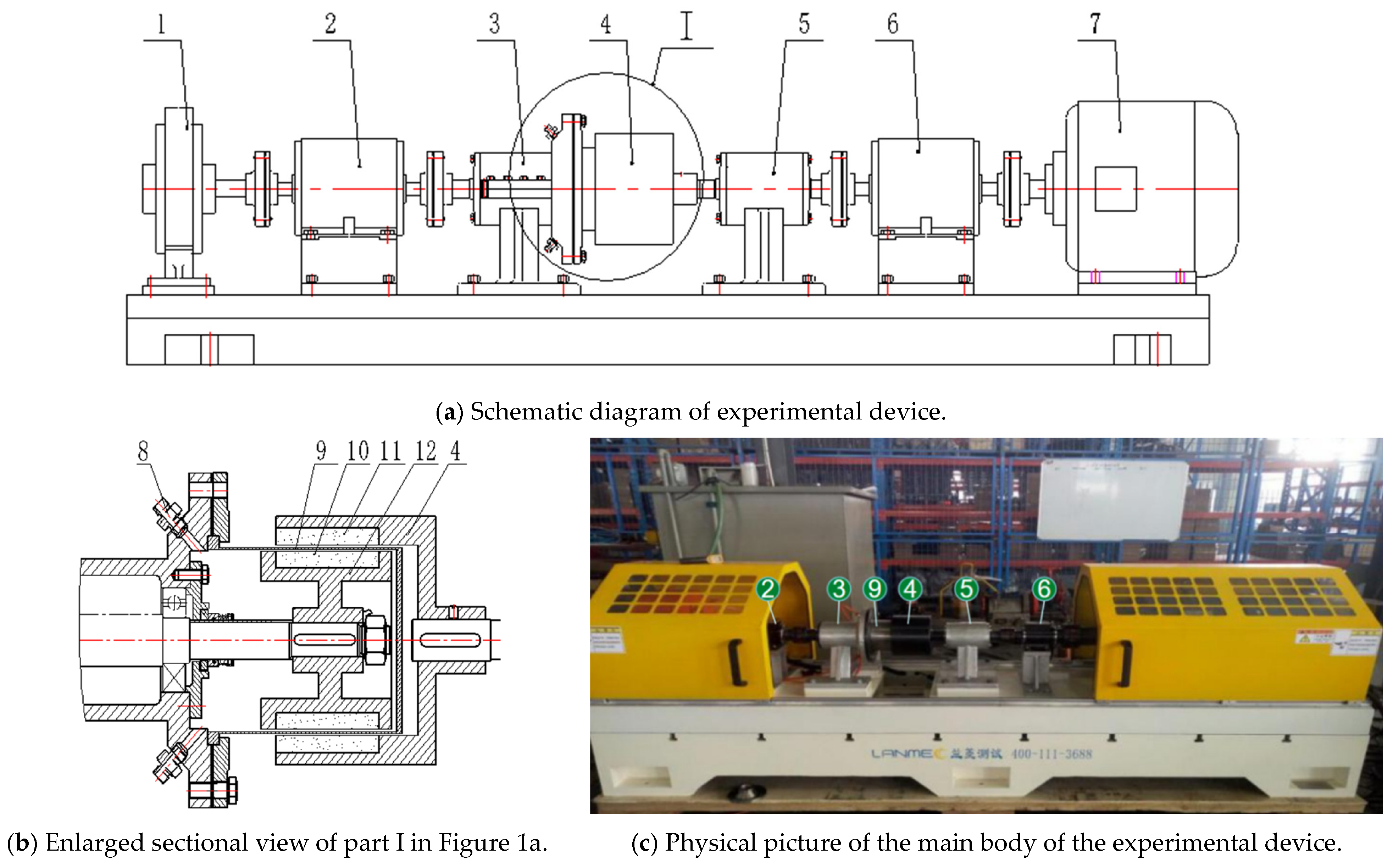
A magnetic coupling transmission performance experimental device for pumps has been established, which consists of the main body of the experimental device, computer control system, 45 kW inverter and cooling system as shown in Figure 1. Figure 1a is the schematic diagram of the experimental device, Figure 1b is an enlarged sectional view of part I in Figure 1a, and Figure 1c is a physical picture of the main parts of the experimental device, which consists of an eddy current brake, two torque and speed sensors, a magnetic coupling, and a variable frequency motor. The eddy current brake loads the output end of the magnetic coupling. The power range of the experimental device is 0~40 kW, the torque range is 0~160 N·m, the speed range is 0~6000 r/min, and the loading accuracy is 0.1% F.S.
Figure 1.
Experimental device of magnetic pump coupling. 1—eddy current brake, 2—output end speed and power tester, 3—output end bearing pedestal, 4—outer magnetic rotor, 5—input end bearing pedestal, 6—input end speed and power tester, 7—variable frequency high-speed motor, 8—cooling medium joint, 9—isolation sleeve, 10—inner magnetic steel, 11—outer magnetic steel, 12—inner magnetic rotor.
The magnetic coupling and eddy current brake need to be cooled; a large amount of heat is taken away by the cooling water, and the water heated by the device flows into the water tank for recycling. The water tank has two water inlets and two water outlets, which are correspondingly connected with the water outlet and the water inlet of the main body of the experimental device through a flexible water pipe, so as to form a cooling circulating loop to cool the coupling, bearing and vortex brake of the experimental device. Meanwhile, the circulating cooling liquid exists as the medium in the coupling.
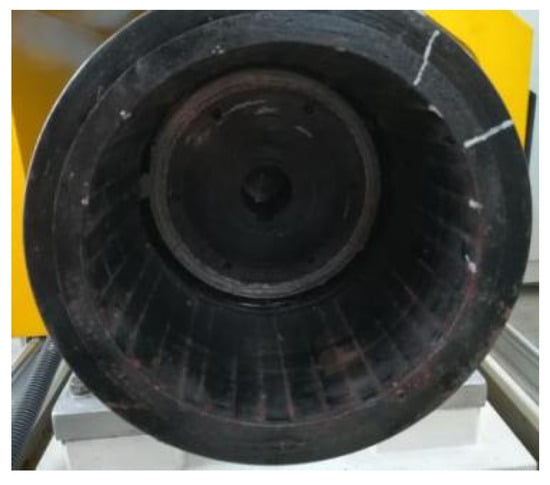
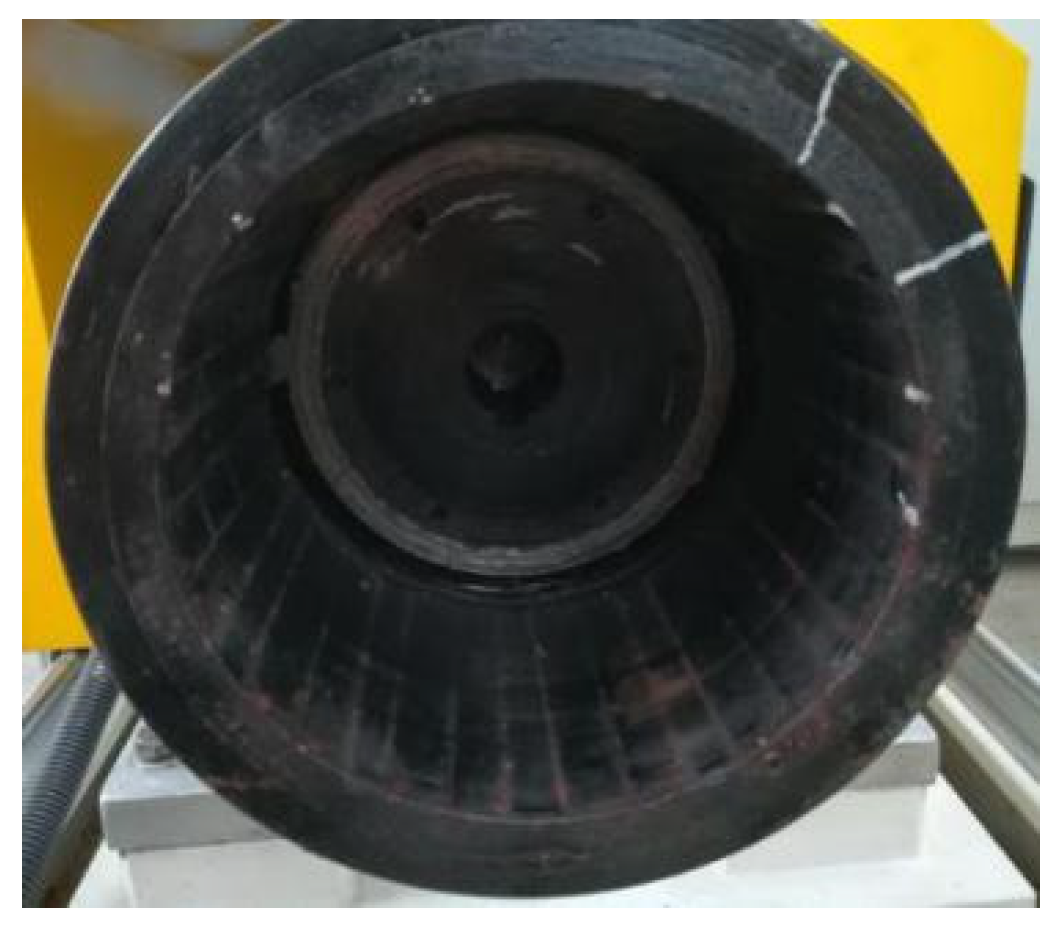
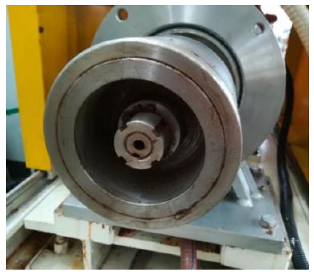
The magnetic coupling used in this study has six pairs of magnetic poles, and neodymium iron boron N38SH was selected as the permanent magnet. The residual magnetic induction intensity Br of neodymium iron boron N38SH is 1.23 T, and the Hc (coercivity of magnetic induction) is 920 kA/m. The magnetic properties of neodymium iron boron permanent magnetic materials are good, with a high Curie temperature of about 310–410 °C. This material has significant magnetic loss at high temperatures and is prone to rusting. Therefore, the surface of the outer magnetic steel in contact with the air of the magnetic coupling is sprayed with paint, while the inner magnetic steel is coated with a sealing layer to prevent rusting. The physical diagram of the external magnetic steel of the magnetic coupling is shown in Figure 2, the physical diagram of the magnetic steel inside the magnetic coupling is shown in Figure 3, and the specific shape, size and material parameters of the magnetic coupling are shown in Table 1. The axial coupling length l of the inner and outer magnetic steel of the magnetic coupling can be adjusted through the track and rocker arm. In the experiment, isolation sleeves made of stainless steel, titanium alloy, and organic glass can be interchanged. Note: in addition to studying the effect of the axial coupling length l of the magnetic steel on eddy current losses, l = 100 mm was used in all other experiments. In addition to studying the effect of isolation sleeve material on eddy current loss, stainless steel was used as the isolation sleeve material in all other experiments.
Figure 2.
Outer magnetic rotor.
Figure 3.
Inner magnetic rotor.
Table 1.
Main structure parameters of magnetic coupling.
4. Results and Discussion
4.1. Experimental Study on Factors Influencing Eddy Current Loss
4.1.1. The Influence of Rotation Speed on Eddy Current Loss
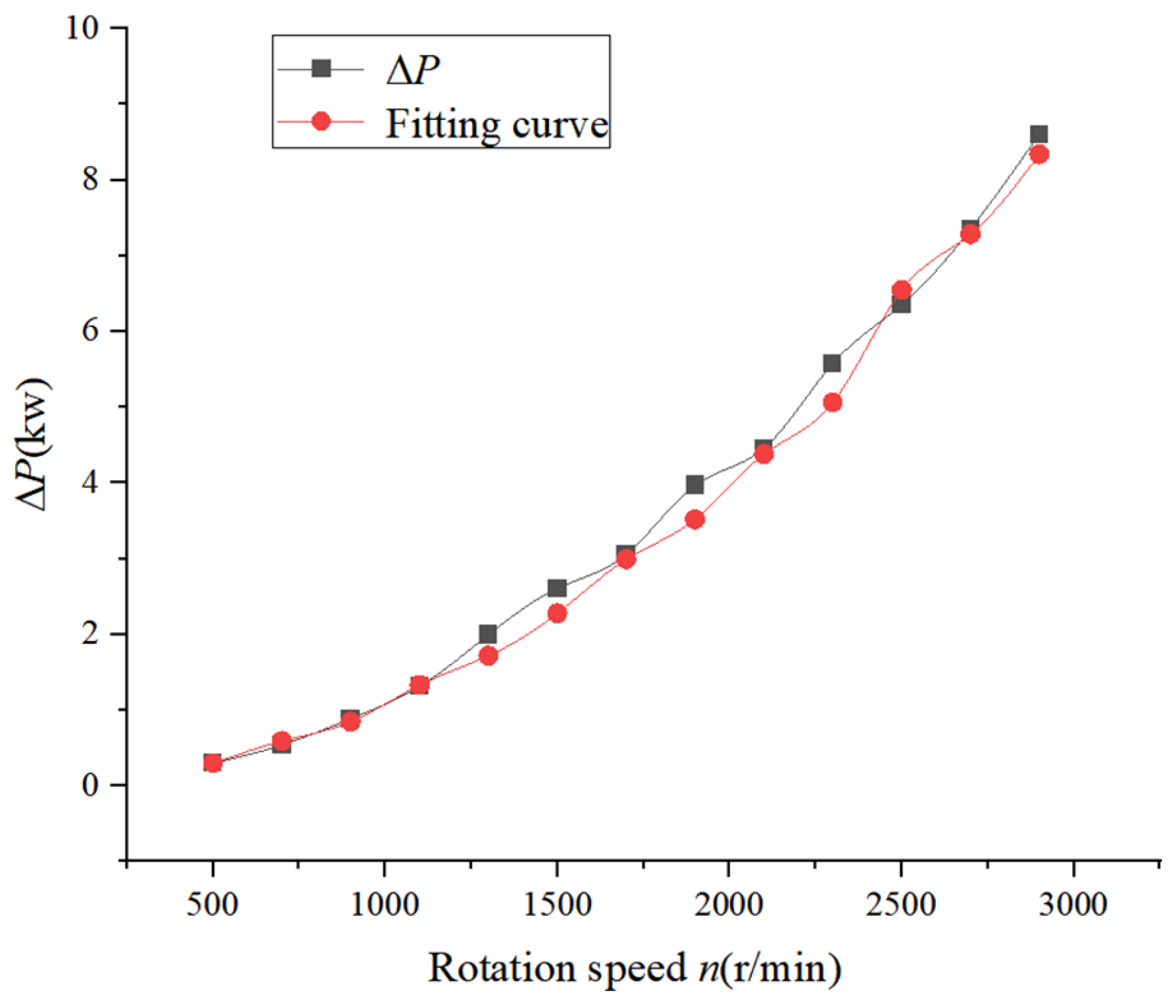
With the aid of a wet magnetic coupling experimental device, the law of influence of rotation speed on eddy current losses is investigated at a rated load of 0 N.m. When the experimental device is operated at a certain speed, the input power P1 and output power P2 of the magnetic pump coupling are measured at this speed; according to the previous analysis, the energy loss is mainly the eddy current loss of the isolation sleeve of the magnetic coupling, and the eddy current loss . Then, slowly remove the load, readjust to another rated speed, and repeat the test many times. The range of regulating speed is 500 r/min~2900 r/min, and the test shall be conducted every 200 r/min. The curve fitting of the eddy current loss of magnetic coupling under different rotating speeds was carried out using Origin 8.0 software, and the fitting model was determined according to the principle of maximum confidence. The eddy current loss and fit at different speeds are shown in Figure 4. It can be seen that the eddy current loss increases with the increase of the rotating speed, and the fitting formula between the eddy current loss and the rotating speed is . This is slightly different from the theoretical Formula (3) in which the eddy current loss is directly proportional to the square of the rotating speed. The main reason is that the energy loss in this test includes the mechanical loss and the friction loss between the magnetic steel inside the isolation sleeve and the liquid medium. Although this component loss is small, it also has a slight influence on the eddy current loss fitting.
Figure 4.
Eddy current loss at different speeds.
4.1.2. The Influence of Axial Coupling Length on Eddy Current Loss
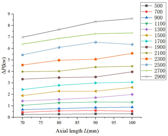
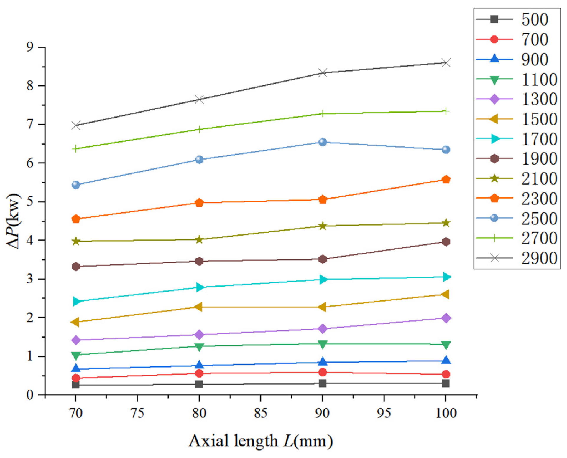
In order to understand the influence of the magnetization length of the magnetic coupling on the eddy current loss of the isolation sleeve, the axial coupling length between the inner magnetic steel and the outer magnetic steel can be approximated as the magnetization length, and positions with axial coupling lengths of 70 mm, 80 mm, 90 mm, and 100 mm can be marked on the isolation sleeve. After aligning the outer magnetic steel with the corresponding position, experiments were conducted to obtain the eddy current losses of the magnetic coupling at different axial coupling lengths and at different speeds, as shown in Figure 5.
Figure 5.
Eddy current loss with different axial coupling lengths at different speeds.
As can be seen from Figure 5, the eddy current loss of the magnetic coupling increases slightly when the axial coupling length increases, and at low rotation speeds, the eddy current loss of the magnetic coupling does not increase significantly with axial length; but at high rotation speeds, the eddy current loss increases significantly with the increase of the axial coupling length. This is consistent with the trend in Equation (3), that the eddy current loss is proportional to the axial magnetization length and the square of the rotation speed. Therefore, at high rotation speeds, the selection of a reasonable magnetic coupling length and length-to-diameter ratio has great influence on optimizing the performance of the magnetic coupling.
4.1.3. The Influence of Isolation Sleeve Material on Eddy Current Loss
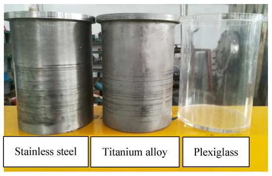
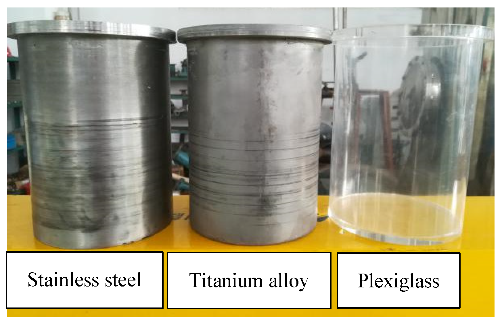
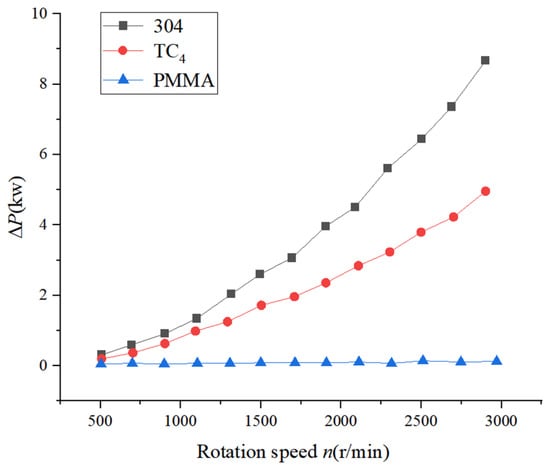
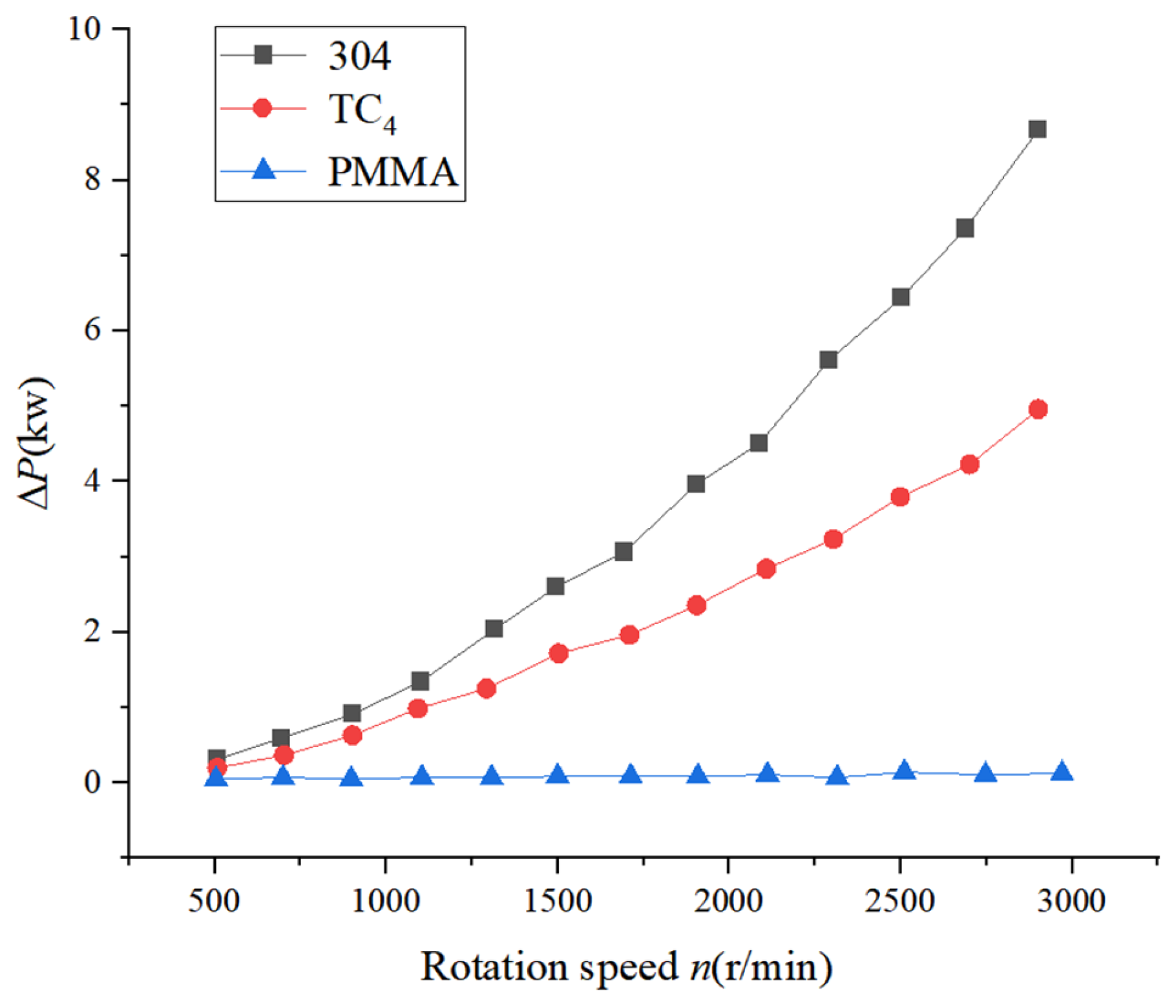
In order to study the effect of isolation sleeve material on eddy current loss, three different materials of isolation sleeves with the same size, namely stainless steel (304), titanium alloy (TC4), and organic glass (PMMA), were manufactured. The physical objects are shown in Figure 6. Due to the brittle material of the organic glass isolation sleeve, it is prone to damage when the bolts are tightened and sealed, resulting in a sealing gap. Therefore, it is necessary to use sealant for sealing. The main physical performance parameters of the three materials, including conductivity σ, thermal conductivity λ, and density ρ, are shown in Table 2. According to Table 2, the ratio of conductivity of 304 stainless steel to TC4 titanium alloy is σ304/σTC4 = 1.66. According to Formula (3), eddy current loss is only related to electrical conductivity and is independent of thermal conductivity and density. By disassembling the flange bolts that fix the isolation sleeve, the isolation sleeve can be replaced while maintaining the axial coupling length of the magnetic coupling at l = 100 mm. The eddy current losses of isolation sleeves made of different materials are shown in Figure 7.
Figure 6.
Isolating covers of different materials.
Table 2.
Physical properties of different materials.
Figure 7.
Eddy current loss of isolation sleeves of different materials.
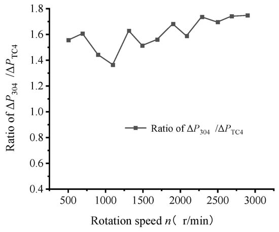
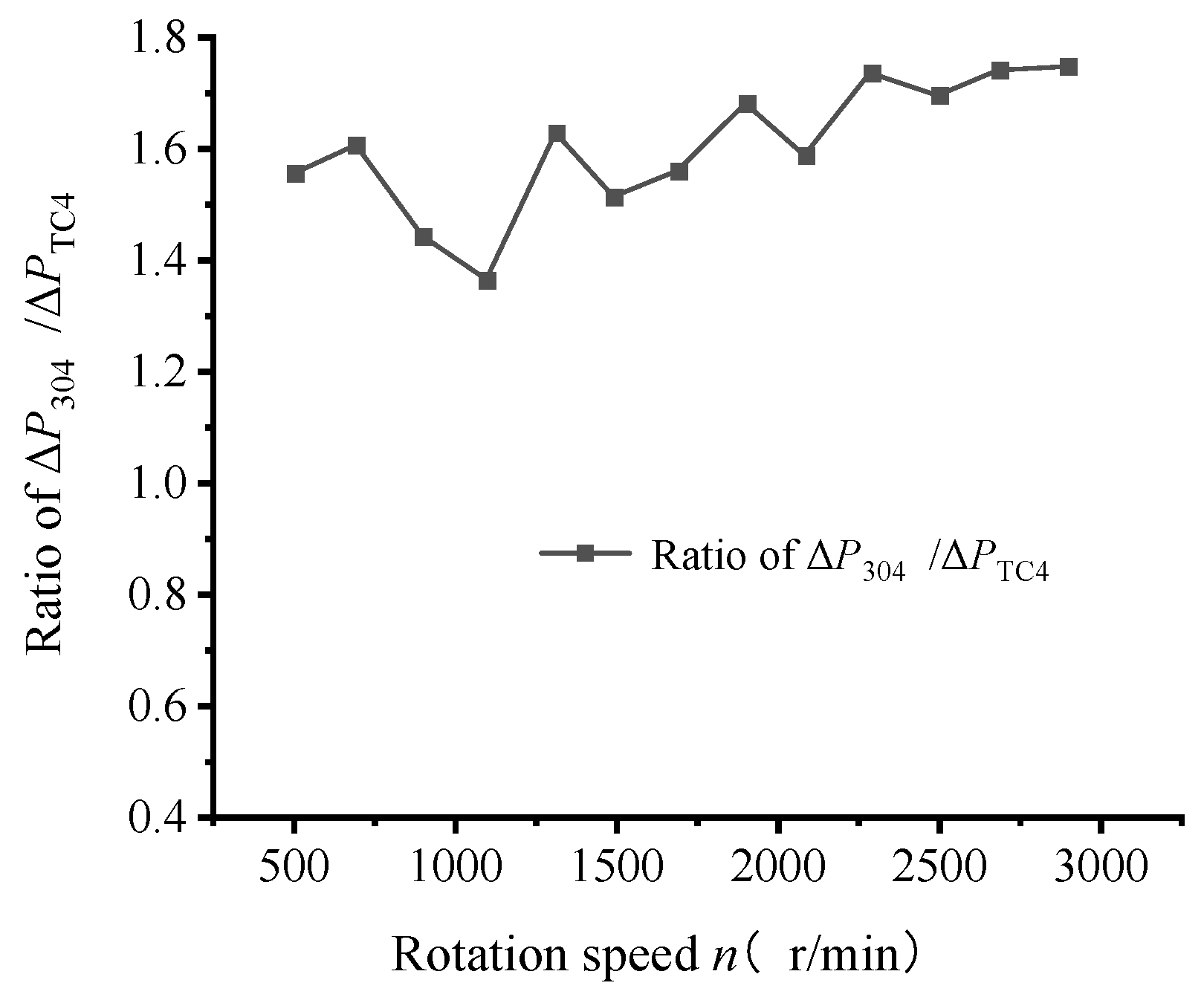
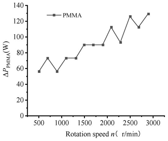
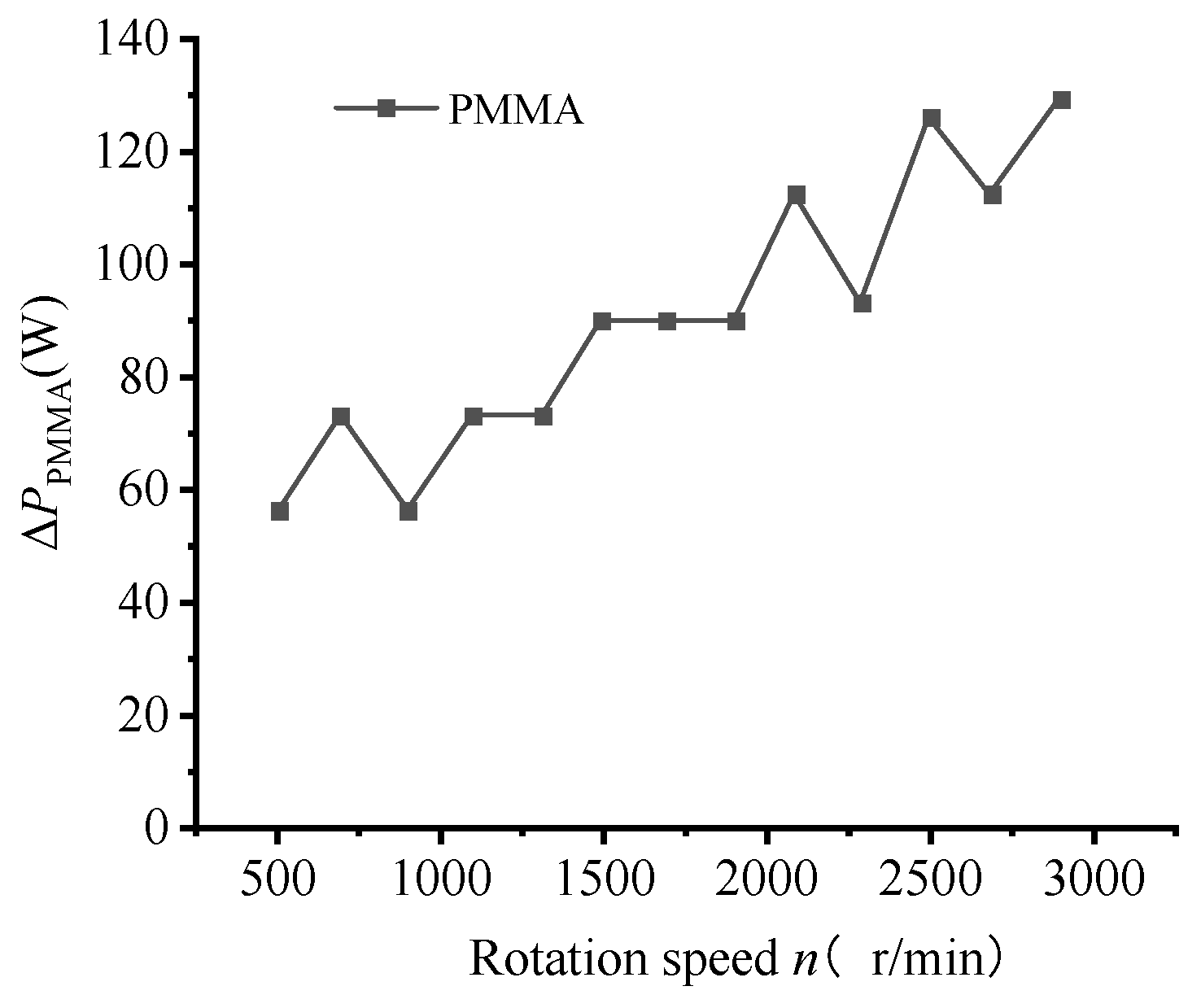
From Figure 7, it can be seen that within any speed range studied, the eddy current loss of the isolation sleeves made of the three materials is P304 > PTC4 > PPMMA. The ratio of eddy current loss of 304 stainless steel to eddy current loss of TC4 titanium alloy at different speeds is shown in Figure 8. Except for a singularity at 1100 r/min, the ratio of other measurement points is relatively stable, with an average value of 1.6, which is close to σ304/σTC4 = 1.66 with an error rate of 3.61%. This confirms that the eddy current loss in Formula (3) is proportional to the conductivity. The conductivity σ of organic glass is almost zero, and its eddy current loss and total energy loss are also extremely small. However, for the other two materials used for isolation sleeves, the eddy current loss increases rapidly due to the increase in conductivity; this verifies the correctness of the previous statement that for metal isolation sleeves, the energy loss is mainly eddy current loss, and the friction loss between the inner magnetic steel and the liquid medium, as well as other losses, are relatively small compared to eddy current loss and can be ignored. As shown in Figure 9, which is an enlarged view of the total energy loss of the organic glass in Figure 7, with the increase of rotation speed, the energy loss of the organic glass isolation sleeve gradually increases from 56.2 W to 129.2 W. The reason for this is that the eddy current loss in this case is almost zero, with the total energy loss being caused mainly by friction losses, pipe losses and other losses.
Figure 8.
Ratio of ΔP304/ΔPTC4 at different speeds.
Figure 9.
ΔPPMMA at different speeds.
4.1.4. The Influence of Fluid Medium on Vortex Loss
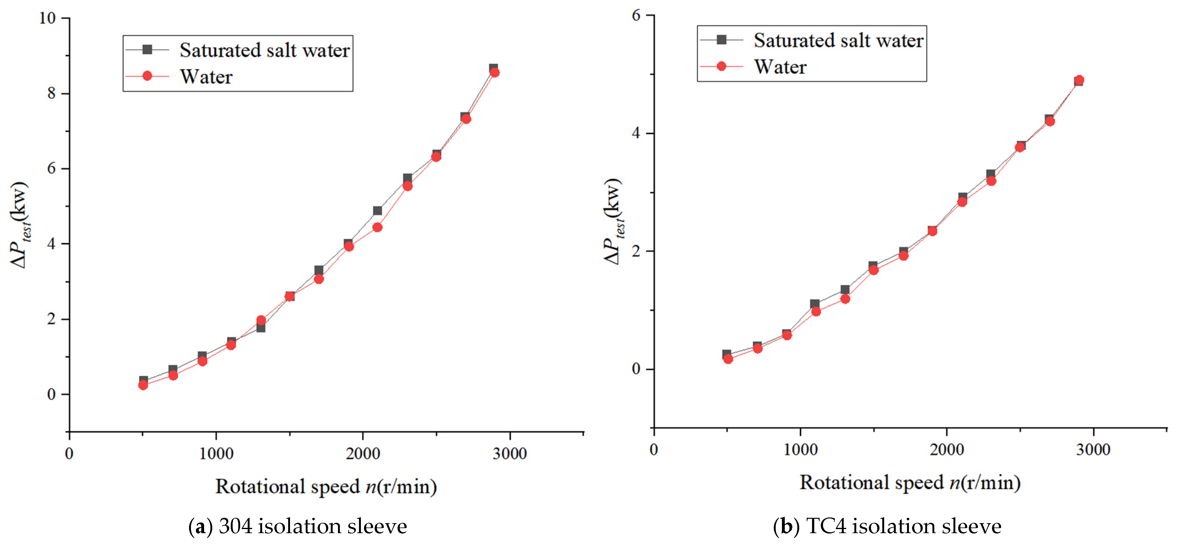
In order to find out whether the physical properties of the conveying and cooling medium inside the pump isolation sleeve, especially the conductivity, have a certain effect on the eddy current loss, the eddy current loss is studied at normal temperature by using low conductivity water and high conductivity saturated salt water (NaCl solution) as media. The physical parameters of both media were measured as shown in Table 3, from which it can be seen that the conductivity of saturated saline solution is 28.16 times that of water.
Table 3.
Related physical properties of fluid media.
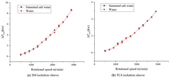
The eddy current loss test results for the stainless steel isolation sleeve and titanium alloy isolation sleeve are shown in Figure 10a and Figure 10b, respectively. As shown, under two different isolation sleeves, the eddy current loss in saturated saline solution medium is slightly greater than the eddy current loss generated with plain water in the medium. The maximum difference in eddy current loss of the stainless steel isolation sleeve is obtained at a speed of 2100 r/min, which is 0.0557 kw, while the maximum difference in eddy current loss of the titanium alloy isolation sleeve is obtained at a speed of 1300 r/min, which is 0.6017 kw. At high speeds, the energy loss is almost the same for different media. The conductivity of saturated saline solution is 28.16 times that of water, and the viscosity is 1.62 times that of water, but the eddy current loss is almost the same. The above results indicate that the influence of the conductivity and viscosity of the flowing medium on eddy current losses can be ignored.
Figure 10.
Eddy current losses of different fluid media.
4.2. Isolation Sleeve Temperature Distribution
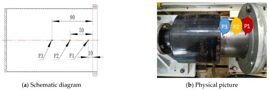
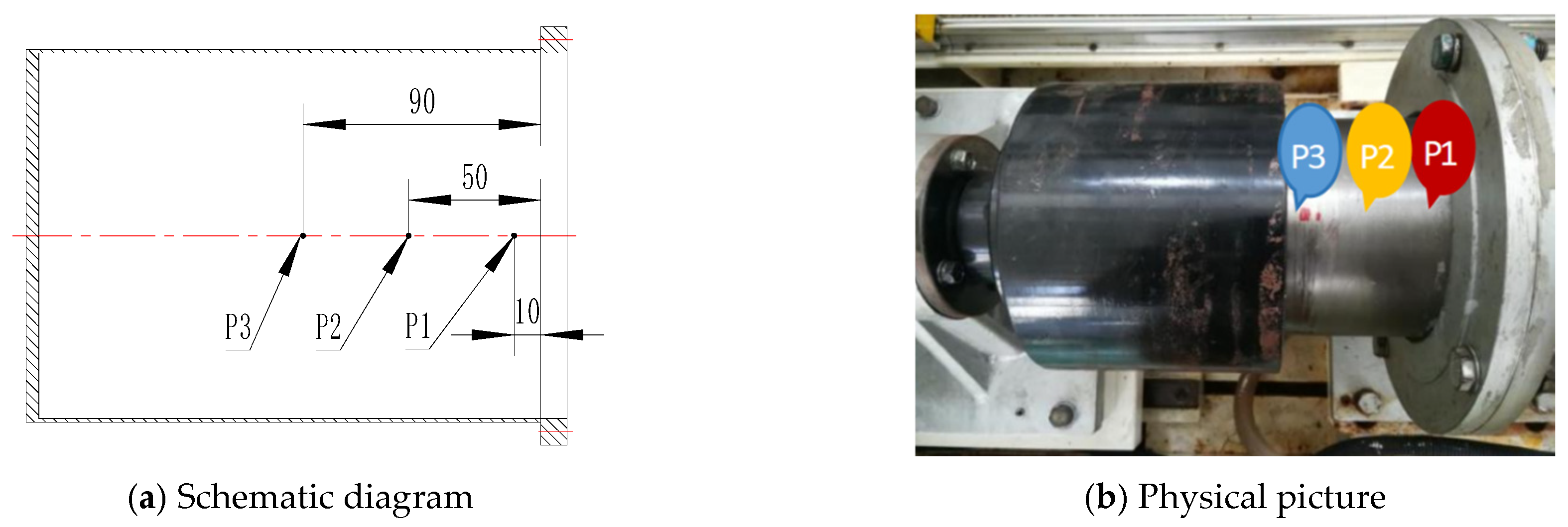
The eddy current loss of the isolation sleeve will cause the temperature of the isolation sleeve, the internal media and the magnetic steel to rise. Excessive temperature rise can cause demagnetization of the magnetic steel, leading to operational failure. Understanding the temperature rise of the isolation sleeve can provide a basis for the design of the cooling circuit. During the experiment on the influence of rotation speed on eddy current loss, infrared temperature guns were used to measure the temperature of the isolation sleeve cylinder surface at positions P1, P2, and P3, as shown in Figure 11.
Figure 11.
Temperature measurement points on the isolation sleeve.
The initial measured temperature on the surface of the isolation sleeve before the experiment was 20.6 °C. The temperature measurement results at the same operating duration (15 min) and different speeds are shown in Table 4.
Table 4.
Temperature measurement results of the isolation sleeve at different speeds.
The temperature measurement points P1, P2, and P3 (10 mm, 50 mm, and 90 mm from the flange position, respectively) are marked on the isolation sleeve. Since the temperature measurement results are related to the magnetic coupling running time, the test time was kept consistent during the test. As can be seen from Table 4, the temperature at different rotation speeds increases from P1 to P3; i.e., along the axial direction away from the bottom of the isolation sleeve, the temperature gradually increases. At low rotation speeds, the eddy current loss of the isolation sleeve is small, so the temperature rise is not obvious; at rotation speeds above 1900 r/min, the temperature rise increases substantially with the eddy current loss. It was also found that when the temperature increased, the load display values of the magnetic coupling were unstable and eddy current losses increased substantially.
5. Conclusions
Tests were conducted to examine the influence of the rotation speed of the pump magnetic coupling, the material of the isolation sleeve, the axial coupling length of the magnetic coupling, the physical parameters of the cooling medium on the eddy current loss of the pump magnetic coupling, and the temperature rise at different positions of the isolation sleeve on an experimental magnetic pumping device. The following conclusions were reached:
- (1)
- The fitting formula for the variation of eddy current loss with rotation speed is .
- (2)
- The eddy current loss increases almost linearly with the axial coupling length of the magnetic coupling.
- (3)
- The eddy current loss increases linearly with the increase of the conductivity of the isolation sleeve material.
- (4)
- The influence of the conductivity and viscosity of the flowing medium on eddy current losses can be ignored.
- (5)
- The friction loss caused by the liquid medium inside the metal isolation sleeve is much lower than the eddy current loss generated by the isolation sleeve, and can be ignored; the energy loss of non-metallic isolation sleeves is mainly due to fluid friction loss and other losses.
- (6)
- The temperature rise is higher near the pump side of the isolation sleeve. The flow distribution of the cooling medium inside the isolation sleeve should be improved at the design stage, and the heat dissipation near the pump side of the isolation sleeve should be strengthened.
The above points provide reference for the design of magnetic coupling for pumps.
Author Contributions
Conceptualization, R.Z.; Validation, J.D., R.Z. and J.S.; Data curation, R.Z.; Writing—original draft, J.W. and J.S.; Writing—review & editing, J.D.; Visualization, J.D.; Funding acquisition, J.W. All authors have read and agreed to the published version of the manuscript.
Funding
This project is funded by the self-supporting program of the Wenling Research Institute of Fluid Mechanics, Jiangsu University (07001).
Data Availability Statement
The original contributions presented in this study are included in the article. Further inquiries can be directed to the corresponding author.
Conflicts of Interest
The authors declare no conflict of interest.
References
- Kowol, P.; Karol, B. Calculations for electromagnetic linear pump with magnetic fluid as movable element. In Proceedings of the 2019 Applications of Electromagnetics in Modern Engineering and Medicine, Janow Podlaski, Poland, 9–12 June 2019. [Google Scholar]
- Ravaud, R.; Lemarquand, G. Magnetic couplings with cylindrical and plane air gaps:influence of the magnet polarization direction. Prog. Electromagn. Res. B 2009, 16, 333–349. [Google Scholar] [CrossRef] [Scilit]
- Akcay, Y.; Tweedy, O.; Giangrande, P.; Galea, M. Design and analysis of a double coaxial magnetic coupling to improve torque density. In Proceedings of the IICON 2021-47th Annual Conference of the IEEE Industrial Electronics Society, Toronto, ON, Canada, 13–16 October 2021. [Google Scholar]
- Aberoomand, V.; Mirsalim, M.; Fesharakifard, R. Design optimization of double-sided permanent-magnet axial eddy-current couplers for use in dynamic applications. IEEE Trans. Energy Convers. 2019, 34, 909–920. [Google Scholar] [CrossRef] [Scilit]
- Seo, K.; Park, G.S. A research on the pumping forces in the magnetic fluid linear pump. IEEE Trans. Magn. 2005, 41, 1580–1583. [Google Scholar]
- Kong, F.Y.; Shen, X.K.; Wang, W.T.; Zhou, S.Q. Performance study based on inner flow field numerical simulation of magnetic drive pumps with different rotate speeds. Chin. J. Mech. Eng. 2012, 25, 137–143. [Google Scholar] [CrossRef] [Scilit]
- Seo, S.W.; Kim, Y.H.; Lee, J.H.; Choi, J.Y. Analytical torque calculation and experimental verification of synchronous permanent magnet couplings with Halbach arrays. AIP Adv. 2018, 8, 056609. [Google Scholar] [CrossRef] [Scilit]
- Tonoli, A.; Amati, N. Dynamic modeling and experimental validation of eddy current dampers and couplers. J. Vib. Acoust. 2008, 130, 021011. [Google Scholar] [CrossRef] [Scilit]
- Strinić, T.; Wex, B.; Jungmayr, G.; Stallinger, T.; Frevert, J.; Panholzer, M. An Alternative Method for Calculating the Eddy Current Loss in the Sleeve of a Sealless Pump. Actuators 2021, 10, 78. [Google Scholar] [CrossRef] [Scilit]
- Mohammadi, S.; Mojtaba, M.; Sadegh, V.-Z.; Heidar, A.-T. Analytical modeling and analysis of axial-flux interior permanent-magnet couplers. IEEE Trans. Ind. Electron. 2014, 61, 5940–5947. [Google Scholar] [CrossRef] [Scilit]
- Ziolkowski, M.; Brauer, H. Fast computation technique of forces acting on moving permanent magnet. IEEE Trans. Magn. 2010, 46, 2927–2930. [Google Scholar] [CrossRef] [Scilit]
- Li, B.F.; Liu, G. A shear model for unsteady state for viscoelastic fluids, based on the correction of torque transfer lag. Phys. Fluids 2019, 31, 023103. [Google Scholar] [CrossRef] [Scilit]
- Lubin, T. Simple analytical expressions for the force and torque of axial magnetic couplings. IEEE Trans. Energy Convers. 2012, 27, 536–546. [Google Scholar] [CrossRef] [Scilit]
- Jiang, Y.; Wang, D.; Chen, J.; Zhang, Q.; Xuan, T. Electromagnetic-thermal-fluidic analysis of permanent magnet synchronous machine by bidirectional method. IEEE Trans. Magn. 2018, 54, 8102705. [Google Scholar] [CrossRef] [Scilit]
- Chen, Y.; Zhu, X.; Quan, L.; Wang, L. Performance analysis of a double-salient permanent-magnet double-rotor motor using electromagnetic–thermal coupling method. IEEE Trans. Appl. Supercond. 2016, 26, 5205305. [Google Scholar] [CrossRef] [Scilit]
- Zhang, G.; Hua, W.; Cheng, M.; Zhang, B.; Guo, X. Coupled magnetic-thermal fields analysis of water cooling flux-switching permanent magnet motors by an axially segmented model. Electromagn. Field Comput. 2017, 53, 8106504. [Google Scholar] [CrossRef] [Scilit]
- Jang, G.H.; Seo, S.W.; Kim, C.W.; Shin, K.H.; Nah, J.; Choi, J.Y. Design of axial flux type permanent magnet coupling with halbach magnet array for optimal performance considering eddy current loss reduction using 3-D finite element method. Int. J. Eng. Technol. 2018, 7, 184–187. [Google Scholar] [CrossRef] [Scilit]
- Hyeon-Jae, S.; Jang-Young, C.; Seok-Myeong, J.; Kwang-Youn, L. Design and Analysis of Axial Permanent Magnet Couplings Based on 3D FEM. IEEE Trans. Magn. 2013, 49, 3985–3988. [Google Scholar]
- Liu, L.; He, L.; Liu, X.; Han, Y.; Sun, B.; Cheng, G. Design and experiment of a low frequency non-contact rotary piezoelectric energy harvester excited by magnetic coupling. Energy 2022, 258, 124882. [Google Scholar] [CrossRef] [Scilit]
- Ravaud, R.; Lemarquand, G.; Lemarquand, V.; Depollier, C. Permanent Magnet Couplings:field and torque three-dimensional expressions based on the coulombian model. IEEE Trans. Magn. 2009, 45, 1950–1958. [Google Scholar] [CrossRef] [Scilit]
- Yuan, D.Q.; He, Y.Q.; Li, J.Q.; Zhang, H.; Chang, C.F. Numerical simulation and experiment of a new drive device of high-temperature magnetic pump. Appl. Mech. Mater. 2010, 26–28, 736–741. [Google Scholar] [CrossRef] [Scilit]
- An, Y.J.; Liu, G.M.; Wang, P.; Wen, H.L.; Meng, Z.J. Magnetic force analysis and experiment of novel permanent magnet axial thrust balance structure in canned motor pump. In Proceedings of the 2nd IEEE International Conference on Advanced Computer Control, Shenyang, China, 27–29 March 2010; Volume 1, pp. 396–398. [Google Scholar]
- Roman, C.; Fireteanu, V.; Vitry, S.; Rey, F. Transient magnetic-Translating motion finite element model of the Annular Linear Induction Pump. In Proceedings of the 2012 International Conference on Applied and Theoretical Electricity, Craiova, Romania, 25–27 October 2012; pp. 25–27. [Google Scholar]
- Wang, J.Q.; Qian, W.F.; Wang, K. Influencing factors of magnetic coupling transmission of magnetic pump. Paiguan Jixie Gongcheng Xuebao 2022, 40, 244–249. [Google Scholar]
- Khan, A.; Yamaguchi, H. On the Rosensweig instability of ferrofluid-infused surfaces under a uniform magnetic field. Phys. Fluids 2023, 35, 113306. [Google Scholar]
- Yamazaki, K.; Yu, F.; Sato, M. Loss Analysis of Permanent-Magnet Motors with Concentrated Windings-Variation of Magnet Eddy-Current Loss Due to Stator and Rotor Shapes. IEEE Trans Ind. Appl. 2009, 45, 1334–1342. [Google Scholar] [CrossRef] [Scilit]
- Lu, M.; Meng, X.; Huang, R.; Chen, L.; Peyton, A.; Yin, W. A high-frequency phase feature for the measurement of magnetic permeability using eddy current sensor. NDT Int. 2021, 123, 102519. [Google Scholar] [CrossRef] [Scilit]
- Simpkin, R. Derivation of Lichtenecker’s Logarithmic Mixture Formula from Maxwell’s Equations. IEEE Trans. Microw. Theory Tech. 2010, 58, 545–550. [Google Scholar] [CrossRef] [Scilit]
- Chen, G. Design and Research of High Speed Magnetic Driven Centrifugal Pump. Master’s Thesis, Jiangsu University, Zhenjiang, China, 2005. [Google Scholar]

Disclaimer/Publisher’s Note: The statements, opinions and data contained in all publications are solely those of the individual author(s) and contributor(s) and not of MDPI and/or the editor(s). MDPI and/or the editor(s) disclaim responsibility for any injury to people or property resulting from any ideas, methods, instructions or products referred to in the content. |
© 2025 by the authors. Licensee MDPI, Basel, Switzerland. This article is an open access article distributed under the terms and conditions of the Creative Commons Attribution (CC BY) license (https://creativecommons.org/licenses/by/4.0/).