


Abstract
Efficiency optimization is an important goal in the design of permanent magnet generators. However, traditional design optimization methods only focus on improving the rated efficiency without considering the annual cycle for overall efficiency improvement. To overcome this drawback, this paper presents a design optimization method for improving annual energy production (AEP) of wind direct-drive permanent magnet generators. Unlike the conventional efficiency optimization method that only improves the rated point efficiency, the proposed method improves the overall efficiency of the generator during the operating cycle by matching the maximum power point trajectory of the wind turbine. The periodic loss model of the permanent magnet generator is established and further constituted as the objective function to perform the optimization search using a genetic algorithm. Through simulation and experimental verification, the proposed method can obtain a higher AEP compared with the conventional design optimization method, and the proposed method can be extended to other variable speed power generation fields.
1. Introduction
As a clean energy resource, wind power has received great research attention and achieved continuous development [1]. Because of their low failure rate and high-power-density, permanent magnet synchronous generators (PMSGs) are increasingly used in wind energy conversion systems (WECSs) [2]. In order to obtain high efficiency, reliable operation, and low cost-effectiveness of WECSs, the generator design optimization is an important aspect [3]. Power electronic converters allow synchronous generators to operate with variable speed while guaranteeing a constant electricity generation frequency [4]. In the period of variable speed operation, the PMSG needs to match the maximum energy trajectory of the turbine by regulating the mechanical speed under different operating conditions. Therefore, for PMSGs of WECSs, it is a new challenge to realize high efficiency operation under variable speed and load during the working cycle.
Currently, intelligent stochastic algorithms such as the genetic algorithm (GA) [5], evolutionary algorithm [6], and other algorithms [7] are commonly utilized to design and optimize the performances of PMSGs. They are mainly based on establishing an analytical or numerical link between structural parameters and generator performance, and then evolving the optimal combination of structural parameters to maximize or minimize the target value by random search and successive iterations.
The optimal design of a PMSG considering the uncertainty of raw material cost is proposed in [8] using a GA, and a hybrid process of GA and pattern search was used to optimize a 6 MW direct-drive PMSG to reduce the cost of energy [9]. In [10], a sensitivity analysis of structural parameters on the performance of a hybrid-excited dual-PM wind generator was carried out, and some leading parameters were identified and further optimized using a combination of finite elements and GA. High efficiency is a valuable optimization goal for generators to increase system energy production and reduce the temperature rise due to operating losses, which has been investigated in many studies [11,12].
However, most of the existing papers are only optimized for rated efficiency, i.e., the objective function only includes the generator efficiency at the rated point, without considering the improvement of the cycle operation efficiency. This may not be applicable to WECSs, where wind turbines are less likely to operate near the rated conditions due to climatic and seasonal influences. Therefore, the classical approach of design optimization with rated efficiency may instead lead to a lower AEP.
In [13], a generator’s operation range is divided into four parts, these four parts are equated into four feature points, and the efficiencies of all four points are optimized collaboratively, allowing the overall efficiency to be enhanced. However, its operating conditions are relatively simple, with a fixed rotational speed of 4200 rpm. For variable speed WECS, the PMG speed needs to rise with increasing input power to improve the energy conversion efficiency, which increases the difficulty of design optimization.
In this paper, a new design optimization method is proposed to maximize the AEP of the PMSG considering the maximum power point trajectory (MPPT) of the wind turbine. First, the aerodynamic model of the wind turbine is introduced to develop the relationship between its MPPT and optimal shaft speed, and the wind speed distribution is investigated to obtain the feature operating points with multiple wind speeds. Secondly, the loss models of the PMSG with multiple feature points are formulated as the objective function, and the GA is utilized to improve the overall efficiency. Finally, the optimization scheme to improve the AEP is obtained and verified by the simulation and experiment.
2. Direct-Drive WECS
2.1. Wind Speed Distribution
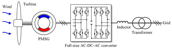
With the elimination of gearboxes in direct-drive WECS, the efficiency and reliability of the system can be improved greatly. The system features a PMSG driven directly by the wind turbine and synchronizes the power generation with the grid frequency through a full-size AC/DC/AC converter, and is capable of variable speed operation in the full speed range, the structure of which is shown in Figure 1.
Figure 1.
Structure of direct-drive WECS.
The wind speed of the wind farm conforms to the Rayleigh distribution [14], and the probability distribution is as follows:
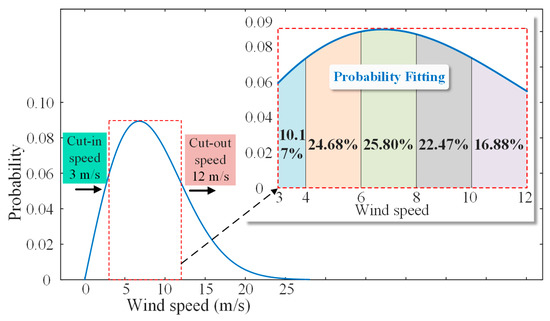
where is the wind speed, is the average value of the wind speed, and the annual average wind speed of the case study is about 8.5 m/s. The cut-in speed is 3 m/s, and the cut-out speed is 12 m/s. The cut-in and cut-out wind speeds are made according to the comprehensive situation of site conditions, the mechanical strength of the generation unit, operating condition characteristics, etc. On the basis of lightweight and large blade design, the cut-out wind speed is therefore relatively lower in this study.
Five feature points are selected to represent the overall distribution of wind speed for design optimization trade-offs, since too many feature points would lead to convergence failure and too few would not be representative. According to the calculation of the definite integral, the probability at each typical wind speed can be obtained as
It can be calculated that is equal to 0.1017 (corresponding to the wind speed range of 3–4 m/s); is 0.2468, (4–6 m/s); is 0.2580 (6–8 m/s); is 0.2247 (8–10 m/s); and is 0.1688 (10–12 m/s). The plotted wind speed curve and the probability fitting results are shown in Figure 2.
Figure 2.
Wind speed Rayleigh distribution and the probability fitting of representative wind speeds.
2.2. Aerodynamic Model of Wind Turbines
The output power (mechanical power ) of the wind turbine is given by [14]
where is the air density, and is the turbine radius. is the wind turbine power coefficient, which is a function of the tip speed ratio λ and the pitch angle , and it can be expressed as
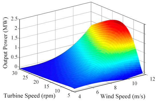
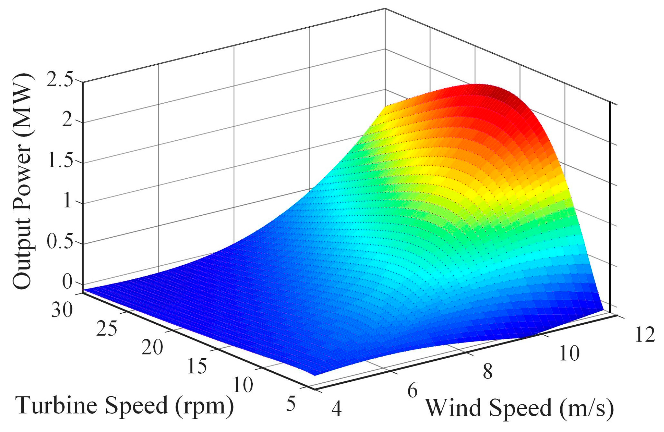
where is the turbine rotational speed. The energy available to the generator is determined by both the wind speed as well as the turbine speed, and their relationship is shown in Figure 3.
Figure 3.
The three-dimensional characteristics of wind turbine energy conversion.
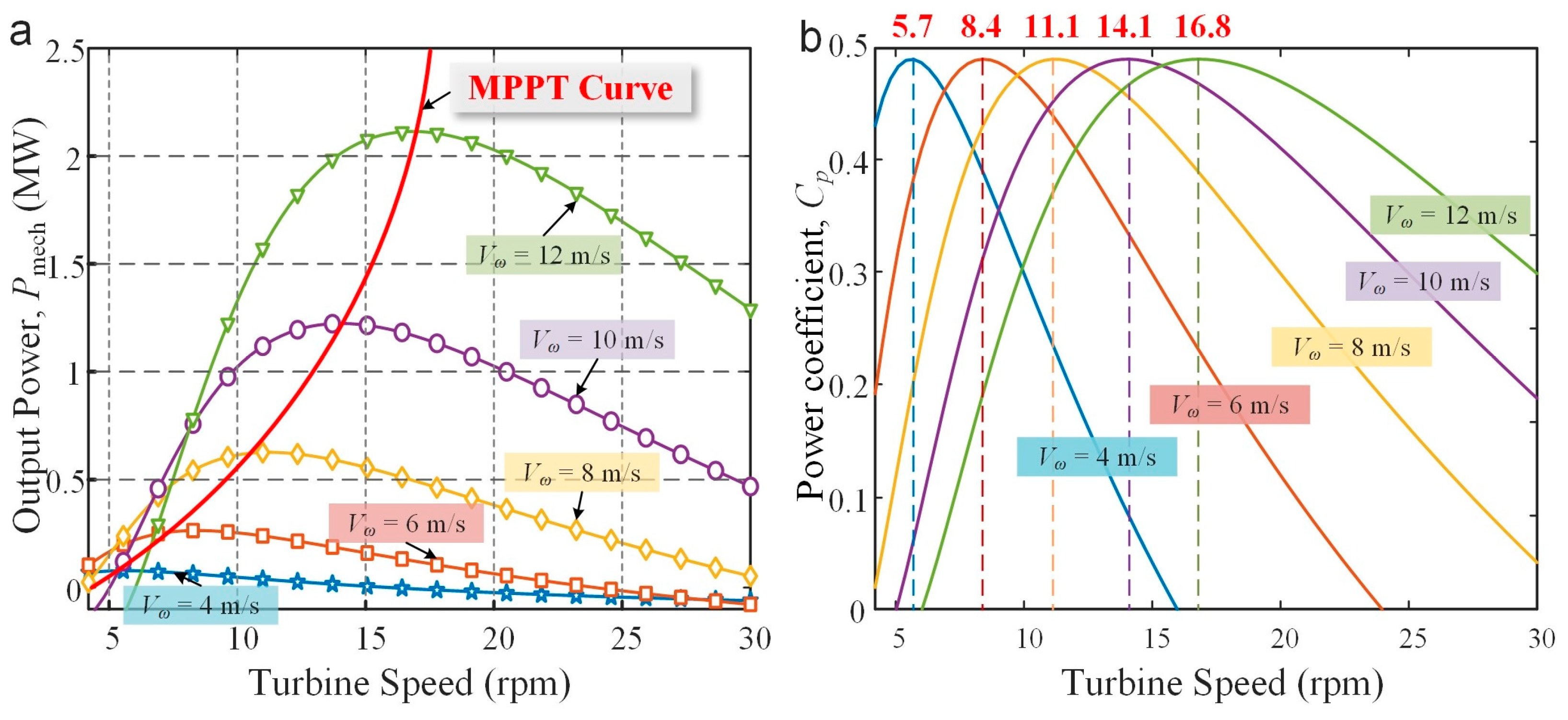
The variable-speed operation of the wind turbine is beneficial to improving the energy conversion efficiency of the system, from which the MPPT curve of the turbine can be obtained, as shown in Figure 4a, and the optimal turbine shaft speed corresponding to the five feature points can also be derived, as shown in Figure 4b.
Figure 4.
Operating characteristics of the wind turbine at representative wind speeds. (a) Output power vs. turbine speed. (b) Power coefficient vs. turbine speed.
Therefore, the actual operating conditions of the generator during the annual cycle can be predicted (including shaft speed, mechanical power, and operating hours) and are concisely represented as five feature operating points, as shown in Table 1. It should be noted that these characteristic points are the basis of the generator’s cycle loss modeling and are closely related to the objective function in the optimization procedure.
Table 1.
Feature operating points of the designed PMSG.
3. Design Optimization
3.1. Optimization Process
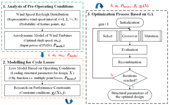
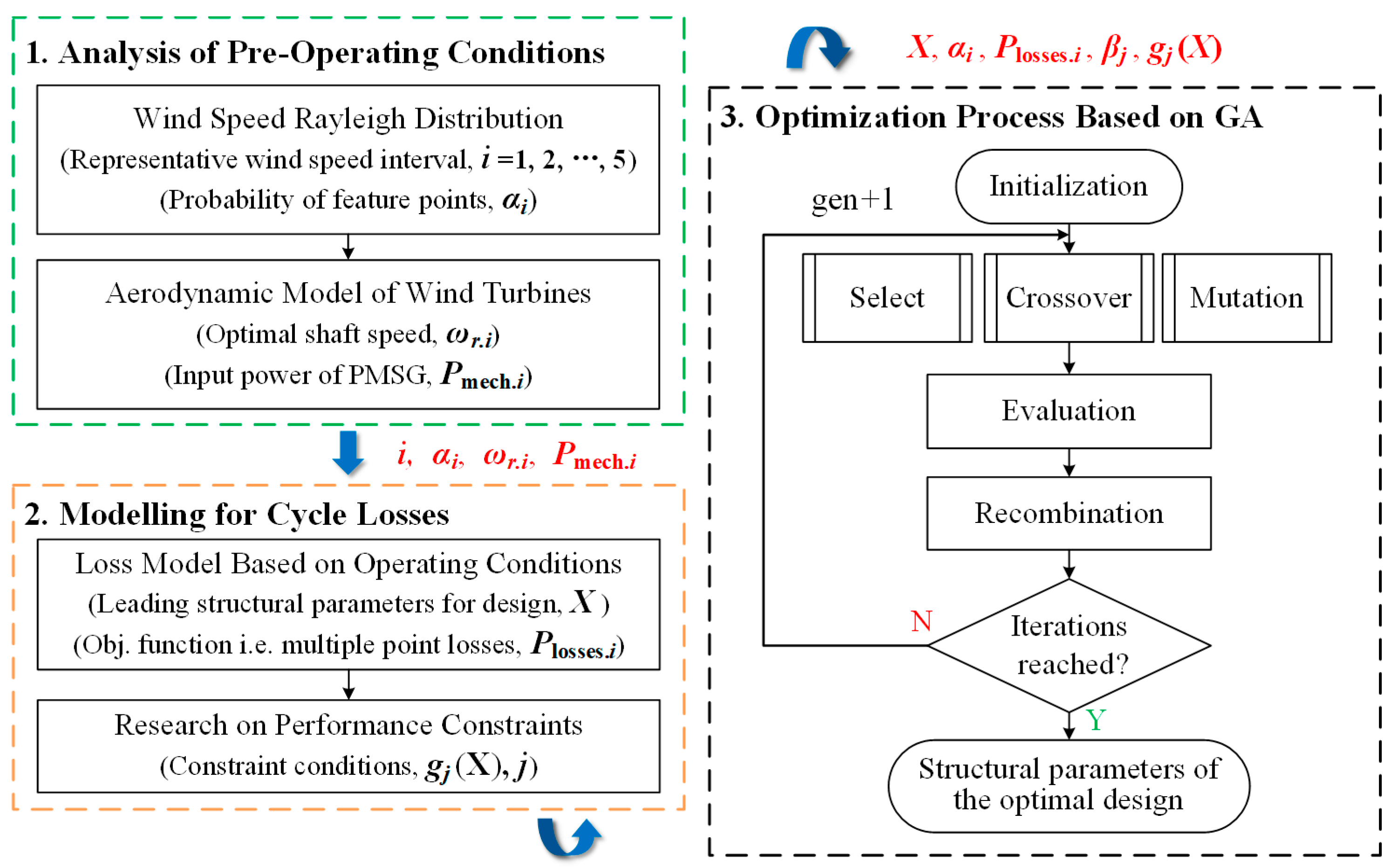
Design optimization is performed by constructing a mathematical correlation between generator structural parameters and losses, and using GA to find the optimal weighted minimum value of losses at multiple feature points so as to obtain the structural parameters of PMSG that achieve the maximum cycle efficiency. The optimization process is shown in Figure 5.
Figure 5.
Flowchart of cycle efficiency design optimization.
As seen from the workflow, the optimization is divided into: (1) operating conditions pre-analysis, (2) cycle loss calculation, and (3) the stochastic algorithm optimization process, of which the operating conditions pre-analysis has been introduced in Section 2. The rest will be introduced in this section, and the optimization process is completed when the number of iterations reaches a set value.
3.2. Modelling for Cycle Losses
The accuracy of the loss model of the PM generators is crucial, and directly determines the validity of the optimization results. The model can provide a straightforward link between structural parameters, operating conditions, and losses.
The losses of permanent magnet synchronous generators come from many sources, and the total losses are expressed as follows [15]
where is the copper Joule loss of stator windings, is the iron core loss including the stator and rotor core, is the eddy current loss of PMs, is the windage loss, and is the friction loss.
First, the Joule loss of copper windings is the main component of PM machine loss, which can be expressed as [16]:
where is the current density, indicating the winding current density per unit area, and is affected by the skin effect and proximity effect; the current density in the winding is not uniformly distributed, especially under high frequency current; is the copper area; and is the electrical resistivity, which is related to the material properties and proportional to the temperature.
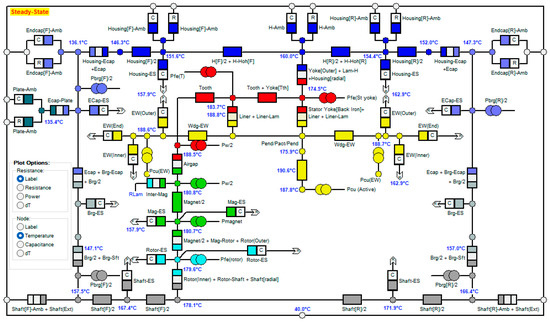
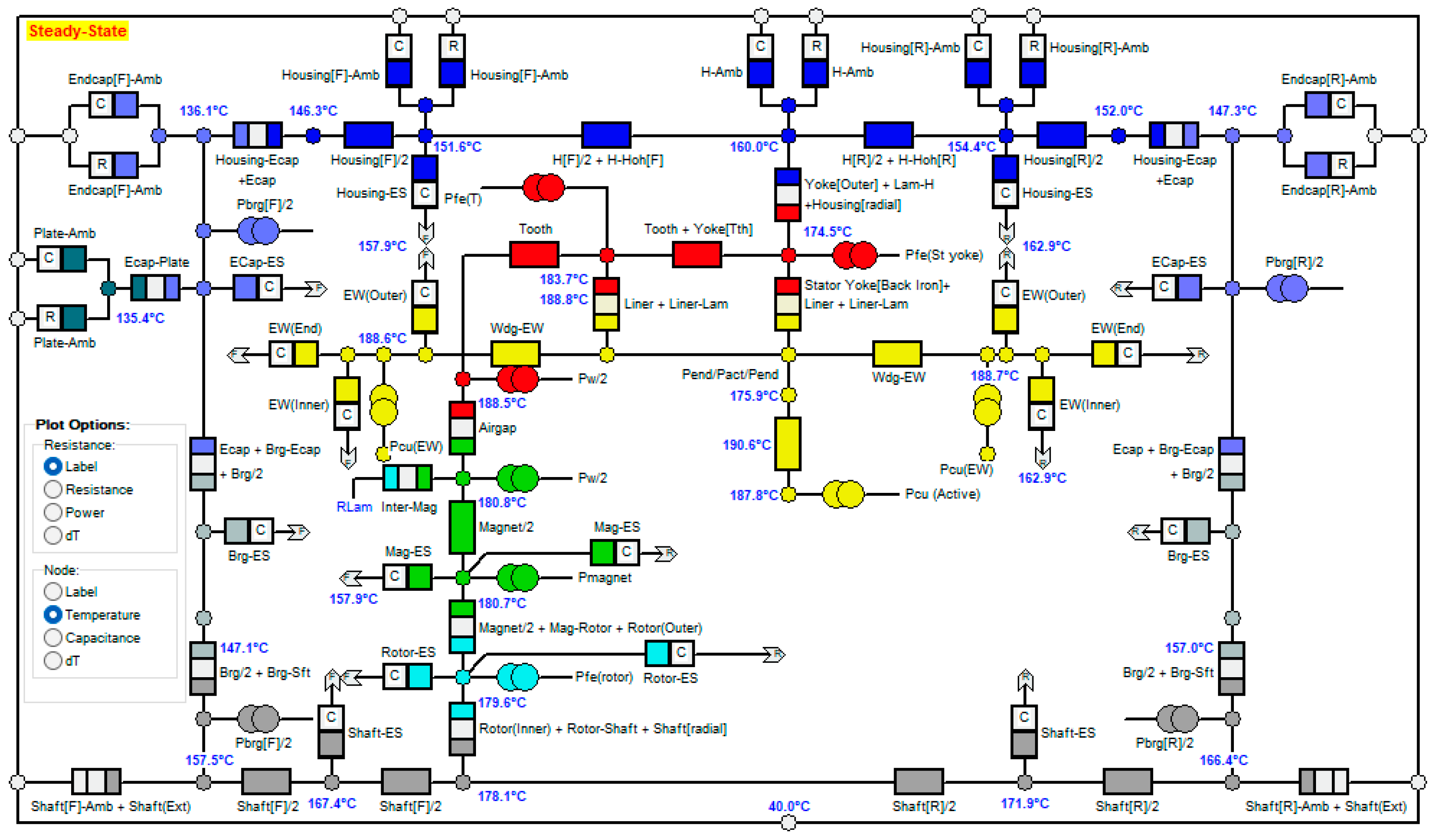
where is the resistivity at 20 °C, about 1.724 × 10⁻⁸ [Ohm·m] for pure copper, is the temperature coefficient, which equals about 0.003862 per degree C, is the winding temperature, and can be solved analytically by the thermal equivalent circuit method or numerically, where the analytical method has a significant computational speed advantage and the numerical method has a more reliable computational accuracy. In order to speed up the optimization process, the thermal network method of ANSYS Motor-CAD is used in this paper. During the iteration of the algorithm, electromagnetic and thermal calculations are required in each design case, and an example of the thermal network calculation diagram for the maximum operating condition of the generator under the natural cooling method is shown in Figure 6.
Figure 6.
Diagram of thermal network circuit solving.
Next, the core loss is also the main component of the PM motor loss, especially in the case of high electrical speed and high magnetic saturation. This accounts for a significant proportion, and the core loss is expressed as follows:
where , are the iron hysteresis and eddy-current loss, respectively, and they are generated in the stator and rotor iron core, and dominated in the stator. They can be expressed as [16].
where is the volume of the iron core, and are the coefficients of hysteresis and eddy-current losses, is the harmonic order of iron flux density, and is the amplitude of the nth harmonic order of flux density. It can be seen that the iron core loss is mainly related to the parameters such as core flux density, operational speed, and iron core volume, etc.
In addition, as a surface-mounted PM machine structure, the eddy current loss of the PMs is also not negligible, and it can be calculated as [17].
where is the electrical resistivity of PMs, , are the radius of the inner and outer PM, respectively, and is the induced eddy current in PMs due to the time-varying armature reaction field, which can be calculated by the 2D finite-element method.
Furthermore, and are the windage and friction losses of the PM generator, respectively, and they are related to the generator structure and the operating speed, etc. Their calculation formula are as follows [18]:
where , are the factors of the windage and friction loss, respectively. is the rotor diameter; is the effective length of the core; is the rotor mass. It can be seen that almost all types of losses are closely related to the generator speed and the input power of the generator.
According to the investigation of the wind turbine operating conditions in Section 2.1, the loss model with multiple feature points can be developed, and the cycle loss function is as follows:
where is the set of design variables, and is the total loss for each feature point.
3.3. Relevant Parameters for Optimization
The fixed parameters of the PMSG to be designed through the preliminary research are shown in Table 2. The material used for the stator and rotor is a silicon steel sheet with 50 mm thickness, and the material used for the PMs is NdFeB of the brand N38UH and has a residual magnetic density of 1.26 T at 20 °C.
Table 2.
Fixed parameters of the designed PMSG.
In order to improve the operating efficiency of the PMSG at multiple wind speeds, a stochastic algorithm is used to find the optimal solution between multiple efficiency objective functions. Furthermore, multiple constraints are considered to rationalize the optimization process. The processing of the objectives and constraints is as follows:
where is the constraint function derived by the design constraints, including the flux density, current density, power density, and slot filling factor; and is the penalty coefficient of the constraint conditions. Table 3 shows the parameters of the constraint conditions.
Table 3.
Parameters of constraint conditions.
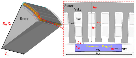
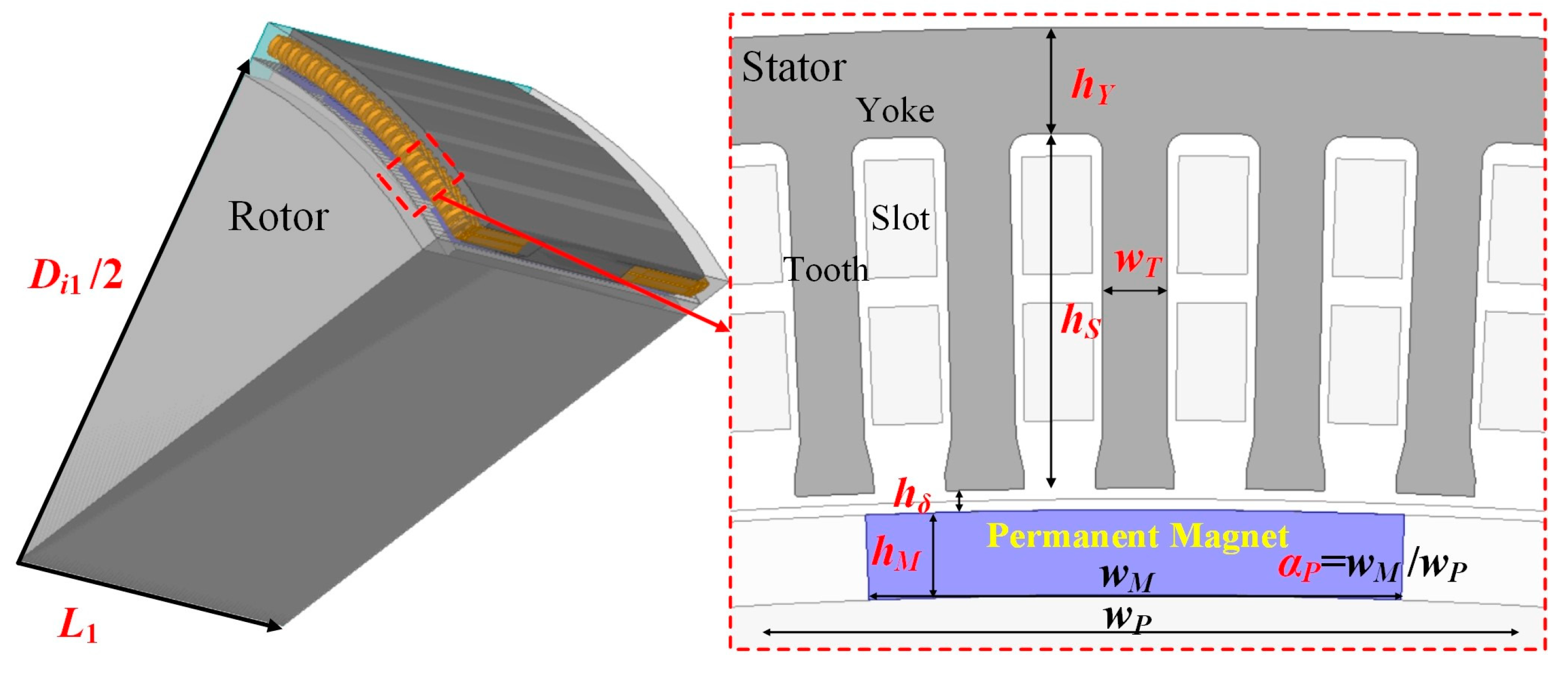
Eight design variables with specific ranges are selected in this paper, as shown in Table 4. Figure 7 shows the PMSG structure and the geometric description of the design variables.
Table 4.
Parameters of the design variables.
Figure 7.
Generator structure and its design parameters.
4. Results and Verification
4.1. Results from Algorithm Calculation
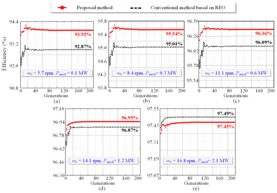
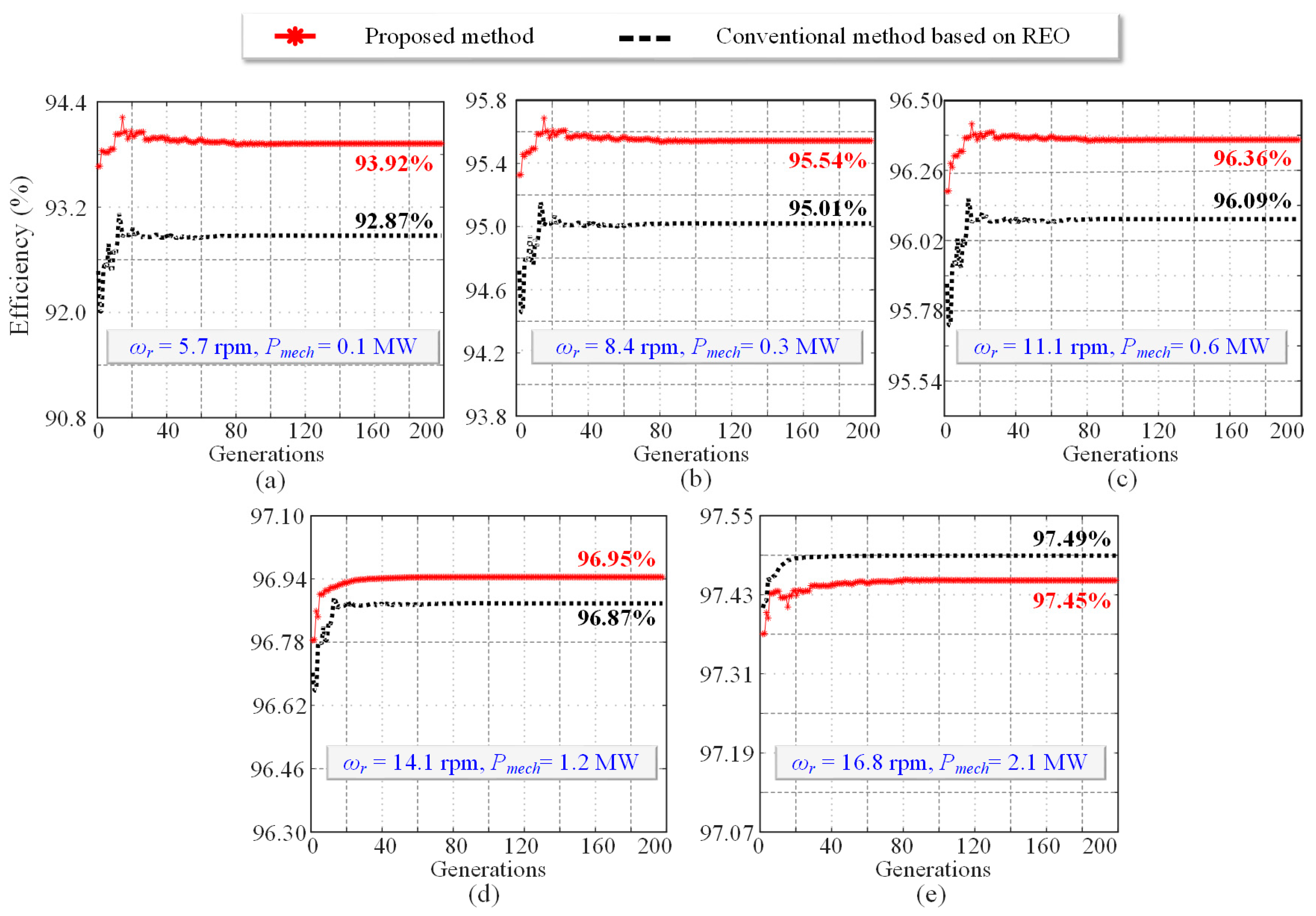
In order to demonstrate the effectiveness of the proposed method for cycle efficiency improvement, a comparison experiment based on rated efficiency optimization (REO) is provided in this paper. The parameters of the two optimization schemes are the same except for the difference of the objective function (the objective function of the comparison experiment is the rated loss of the generator). The genetic algorithm was used to optimize the two optimization schemes in turn. For the trade-off between convergence and computational time, the number of iterations is set to 200 in this paper, and it can be seen in Figure 8 that multiple efficiencies have converged. The two optimization schemes are optimized by GA in turn. Each population of GA contains 500 individuals, and the number of generations is 200. After the iterative calculations, the variation of the fitness values for each feature operating condition is shown in Figure 8. The optimized design parameters of the proposed method are shown in Table 5.
Figure 8.
Iterative optimization of the proposed method and the conventional method based on REO. (a) Generator efficiency at the wind speed of 4 m/s. (b) Generator efficiency at the wind speed of 6 m/s. (c) Generator efficiency at the wind speed of 8 m/s. (d) Generator efficiency at the wind speed of 10 m/s. (e) Generator efficiency at the wind speed of 12 m/s.
Table 5.
Optimized design parameters.
From the comparison in Figure 8, it can be seen that the conventional optimization method is effective in optimizing the rated point efficiency, which is 97.49% for a wind speed of 12 m/s, 96.87% for 10 m/s, 96.09% for 8 m/s, 95.01% for 6 m/s, and 92.87% for a wind speed of 4 m/s, while its cycle-weighted efficiency is 95.91%. On the other hand, the proposed optimization method has a higher cycle efficiency, which is 97.45% for a wind speed of 12 m/s, 96.95% for 10 m/s, 96.36% for 8 m/s, 95.54% for 6 m/s, 93.92% for a cycle-efficiency of 4 m/s, and a cycle-weighted efficiency of 96.23%. In summary, the proposed method has a higher annual cycle efficiency than the conventional REO-based method, with a weighted average efficiency of 0.32% higher.
4.2. Simulation Verification
The optimized design parameters were brought into the finite-element electromagnetic Ansys Maxwell software, and the simulated performances of the designed PMSG under various operating conditions is shown in Table 6. The results show that the performance indicators are well within the constraint conditions, and the generator has high operating efficiency under different operating conditions.
Table 6.
Simulation performance of the optimized PMSG.
4.3. Experimental Verification
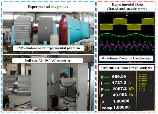
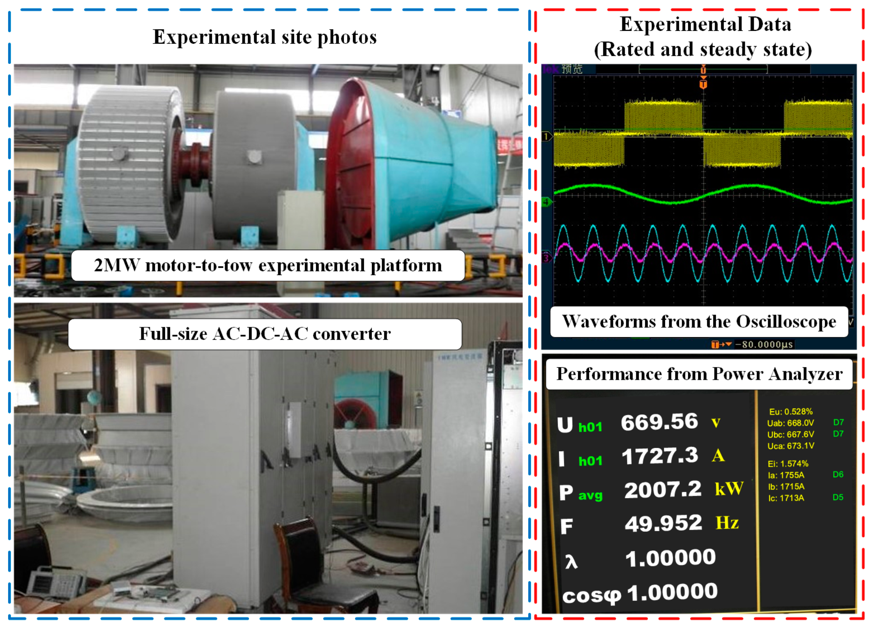
The designed PMSG was fabricated and assembled, and its performance was tested on a dragging experimental platform. The photos of the test site and the performance demonstration are shown in Figure 9. The efficiencies obtained from the tests and model calculations at different speeds and powers are shown in Table 7. The results show that the experimental data are closer to the model calculations, and the effectiveness of the proposed method can be verified.
Figure 9.
Experimental site photos and performance demonstration.
Table 7.
Comparison of the efficiency data between model calculations and experiments.
5. Conclusions
This paper presented a design optimization method for direct-drive wind PMSGs to improve the AEP of WECSs. The proposed method considered the optimal trajectory of the wind turbine and optimized the efficiency of several feature operating points in an integrated manner, and the method was compared with the conventional design optimization method based on the rated point efficiency. The computational results of the algorithm showed that the proposed method effectively improved the annual weighted efficiency by 0.32%, and the designed generator was validated by simulation and an experimental platform.
The proposed method is not only applicable to the design of wind turbines, but also has implications for the design and optimization of other electric machines with variable speeds and variable operating conditions.
Author Contributions
Methodology, W.Z.; Software, W.F. and H.Z.; Validation, H.Y., W.Z. and H.Z.; Formal analysis, W.Z. and L.D. All authors have read and agreed to the published version of the manuscript.
Funding
This work was supported in part by the Natural Science Foundation of China (52277034) and the Changsha Major Science and Technology Special Project of China (kq2205003).
Conflicts of Interest
The authors declare no conflict of interest.
References
- Yaramasu, V.; Wu, B.; Sen, P.C.; Kouro, S.; Narimani, M. High-power wind energy conversion systems: State-of-the-art and emerging technologies. Proc. IEEE 2015, 103, 740–788. [Google Scholar] [CrossRef] [Scilit]
- Gao, J.; Dai, L.T.; Zhang, W.J. Improved genetic optimization algorithm with subdomain model for multi-objective optimal design of SPMSM. CES Trans. Elect. Mach. Syst. Mar. 2018, 2, 160–165. [Google Scholar] [CrossRef] [Scilit]
- Xu, Y.; Maki, N.; Izumi, M. Overview Study on Electrical Design of Large-Scale Wind Turbine HTS Generators. IEEE Trans. Appl. Supercond. 2018, 28, 1–5. [Google Scholar] [CrossRef] [Scilit]
- Borkowski, D.; Wegiel, T. Small Hydropower Plant with Integrated Turbine-Generators Working at Variable Speed. IEEE Trans Energy Conv. Jun. 2013, 28, 452–459. [Google Scholar] [CrossRef] [Scilit]
- Zhang, P.; Sizov, G.Y.; Li, M.; Ionel, D.M.; Demerdash, N.A.O.; Stretz, S.J.; Yeadon, A.W. Multi-Objective Tradeoffs in the Design Optimization of a Brushless Permanent-Magnet Machine with Fractional-Slot Concentrated Windings. IEEE Trans. Ind. Appl. 2014, 50, 3285–3294. [Google Scholar] [CrossRef] [Scilit]
- Sindhya, K.; Manninen, A.; Miettinen, K.; Pippuri, J. Design of a Permanent Magnet Synchronous Generator Using Interactive Multiobjective Optimization. IEEE Trans. Ind. Electron. Dec. 2017, 64, 9776–9783. [Google Scholar] [CrossRef] [Scilit]
- de Paula Machado Bazzo, T.; Kölzer, J.F.; Carlson, R.; Wurtz, F.; Gerbaud, L. Multiphysics Design Optimization of a Permanent Magnet Synchronous Generator. IEEE Trans. Ind. Electron. Dec. 2017, 64, 9815–9823. [Google Scholar] [CrossRef] [Scilit]
- Pinilla, M.; Martinez, S. Optimal design of permanent-magnet direct-drive generator for wind energy considering the cost uncertainty in raw materials. Renew. Energy 2012, 41, 267–276. [Google Scholar] [CrossRef] [Scilit]
- McDonald, A.; Bhuiyan, N.A. On the Optimization of Generators for Offshore Direct Drive Wind Turbines. IEEE Trans. Energy Convers. 2017, 32, 348–358. [Google Scholar] [CrossRef] [Scilit]
- Zhao, X.; Niu, S.; Fu, W. Sensitivity Analysis and Design Optimization of a New Hybrid-Excited Dual-PM Generator With Relieving-DC-Saturation Structure for Stand-Alone Wind Power Generation. IEEE Trans. Magn. 2020, 56, 1–5. [Google Scholar] [CrossRef] [Scilit]
- Wang, Q.; Niu, S.; Yang, L. Design Optimization of a Novel Scale-Down Hybrid-Excited Dual Permanent Magnet Generator for Direct-Drive Wind Power Application. IEEE Trans. Magn. 2018, 54, 1–4. [Google Scholar] [CrossRef] [Scilit]
- Sabioni, C.L.; Ribeiro, M.F.O.; Vasconcelos, J.A. Robust Design of an Axial-Flux Permanent Magnet Synchronous Generator Based on Many-Objective Optimization Approach. IEEE Trans. Magn. 2018, 54, 1–4. [Google Scholar] [CrossRef] [Scilit]
- Gao, J.; Dai, L.; Zhang, W.; Huang, S.; Wu, X. Multi-interval Efficiency Design Optimization for Permanent Magnet Synchronous Generators Used in Hybrid Electric Special Vehicles. IEEE Trans. Ind. Electron. 2021, 68, 4646–4656. [Google Scholar] [CrossRef] [Scilit]
- Eriksson, S.; Bernhoff, H. Loss evaluation and design optimisation for direct driven permanent magnet synchronous generators for wind power. Appl. Energy 2011, 88, 265–271. [Google Scholar] [CrossRef] [Scilit]
- Liu, C.; Chau, K.T.; Lee, C.H.T.; Song, Z. A Critical Review of Advanced Electric Machines and Control Strategies for Electric Vehicles. Proc. IEEE 2020, 109, 1004–1028. [Google Scholar] [CrossRef] [Scilit]
- Belahcen, A.; Arkkio, A. Permanent magnets models and losses in 2D FEM simulation of electrical machines. In Proceedings of the XIX International Conference on Electrical Machines—ICEM 2010, Rome, Italy, 6–8 September 2010; pp. 1–6. [Google Scholar] [CrossRef] [Scilit]
- Ishak, D.; Zhu, Z.Q.; Howe, D. Eddy-current loss in the rotor magnets of permanent-magnet brushless machines having a fractional number of slots per pole. IEEE Trans. Magn. 2005, 41, 2462–2469. [Google Scholar] [CrossRef] [Scilit]
- Zarko, D. A Systematic Approach to Optimized Design of Permanent Magnet Motors with Reduced Torque Pulsations. Ph.D. Dissertation, Univ. Wisconsin—Madison, Madison, WI, USA, 2004. [Google Scholar]


Disclaimer/Publisher’s Note: The statements, opinions and data contained in all publications are solely those of the individual author(s) and contributor(s) and not of MDPI and/or the editor(s). MDPI and/or the editor(s) disclaim responsibility for any injury to people or property resulting from any ideas, methods, instructions or products referred to in the content. |
© 2023 by the authors. Licensee MDPI, Basel, Switzerland. This article is an open access article distributed under the terms and conditions of the Creative Commons Attribution (CC BY) license (https://creativecommons.org/licenses/by/4.0/).