


Abstract
This paper presents a novel method for current control for a modular multilevel converter (MMC). The proposed current control methodology is based on a modified sliding mode control (SMC) with proportional and integral (PI) sliding surface which allows fast transient responses and improves the robustness of the MMC control performance. As the proposed method is derived via Lyapunov direct method, the closed-loop stability is ensured and results in globally asymptotically stable. Furthermore, the reaching time is also guaranteed by the proposed method, leading to fast transient responses. The proposed method is validated by comparing with some existing methods, which are proportional integral controller and conventional SMC, via offline and hardware-in-loop (HIL) simulations where a 10 MW, medium-voltage MMC system is tested. According to these results, the proposed method is able to provide fast transient responses, zero overshoot, and robustness to the weak grid and short-circuit conditions.
1. Introduction
Renewable energy (RE) technologies offer the promise of clean, abundant energy gathered from self-renewing resources such as the sun and wind [1]. In fact, power grids have managed the ever-increasing shares of RE, as evident from the fact that there was an increase of of renewable electricity generation in the first quarter of year 2020, compared to that of 2019 [2].
To extract the RE, power converters are used as interface from renewable sources to the grid or load. A voltage source converter (VSC) is the main interconnection device for distributed generators (DGs) and energy storage systems. According to their topologies, VSCs are categorized into two-level VSCs [3], cascaded multilevel converters [4], diode-clamped VSCs [5], flying capacitor converters [4], and MMCs [6]. Among them, an MMC provides modular and scalable structures which can satisfy any voltage requirements. In addition, the superior harmonic performance can be generated by this converter since the the output voltage is produced based on stacking-up of a large number of identical submodules (SMs) leading to a sinusoidal voltage waveform with less filtering effort. Due to its feature, this converter is suitable for medium- and high-voltage applications, e.g., high-power motor drives [7], high-voltage direct current transmission (HVDC) [8], unified power flow controller (UPFC) [9], and static synchronous compensators (STATCOM) [10,11]. Moreover, for grid-connected PV systems [12], modular multilevel inverters are the preferred solution to connect large-scale PV plants [13] to the medium-voltage (MV) grid because then the costly and bulky transformer can be removed.
Various control strategies from the classical to the more advanced ones have been devoted to regulate the current and power of MMCs. Proportional integral (PI) [14,15] and proportional resonant (PR) controllers [16,17] have been applied for MMC control. However, when the power system is subjected to uncertain disturbances, the performance of both controllers will be degraded. To overcome the influence of uncertainties, there have been various nonlinear controllers proposed to deal with this issue. Predictive control methods have been employed to regulate the grid-side current of MMCs [18]. The control signal is obtained by minimizing the cost function, which is a function of the error. The Lagrange-based optimization is then used to solve iteratively in every sampling time, which may suffer from computational burden. Furthermore, the optimality may be achieved, but the stability cannot be ensured. Although the computational effort has been reduced by [19], the robustnessof the system has not been investigated yet. Such uncertainty occurrences may lead to system instability. The feedback linearization has been proposed to control the MMC output current [20]. However, the control design is based on a linearized model. Recently, the application of sliding mode control (SMC) in power converters has attracted the attention of researchers because it has many advantages compared to other types of controllers. SMC is a nonlinear controller which provides robust features for parameter variations and is insensitive to uncertainties. In addition, SMC is relatively easy to implement in the system. Nevertheless, in SMC, the discontinuous control signal causes a phenomenon called chattering [21]. There are many ways to reduce the chattering phenomenon. One of them is called second-order sliding mode control (SOSMC) [22]. The concept of the SOSMC is to convert the discontinuous function into a continuous function by employing higher-order derivative of the control signals. Chattering phenomenon is also commonly caused by high switching gain applied to compensate the system uncertainties. The high switching gain will cause the system to be overconservative, so that the control signal provided is too excessive and causes chattering. To overcome these problems, the saturation function replaces the sign function. Yang et al. implemented the SMC in MMC control [23]. However, the sliding surface is based on conventional one. The conventional sliding surface can ensure that the plant will be converged in finite time, but the steady-error cannot be eliminated. Ishfaq et al. proposed an SMC controller which is called the super-twisting controller (STC) [24]. The advantage of the STC is the ability to prevent chattering, and the controller design is not based on the time derivative of the sliding variable. However, if the sliding surface is not properly selected for the STC, the result may lead to an unacceptable performance. Uddin et al. [25] designed a controller to control both output current and circulating current along with suppression of second harmonics contents in circulating current. The switching law is also based on the super-twisting algorithm.
In this paper, a new control method based on SMC with integral surface is proposed for an MMC. The integral sliding surface is employed to eliminate the steady-state error and improve the performance of the closed-loop system. To demonstrate the practicability of the proposed method, a hardware-in-the-loop (HIL) simulation for an MMC was implemented.
2. Modular Multilevel Converter Modeling
2.1. Modular Multilevel Converter Modeling
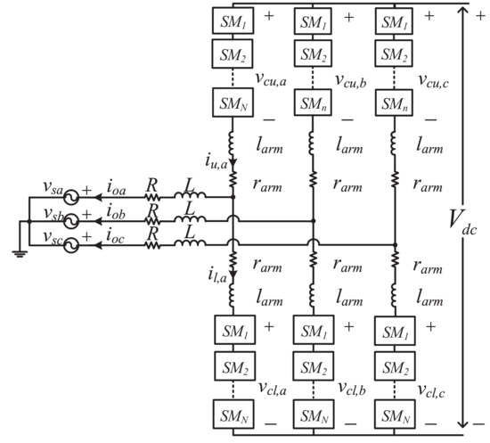
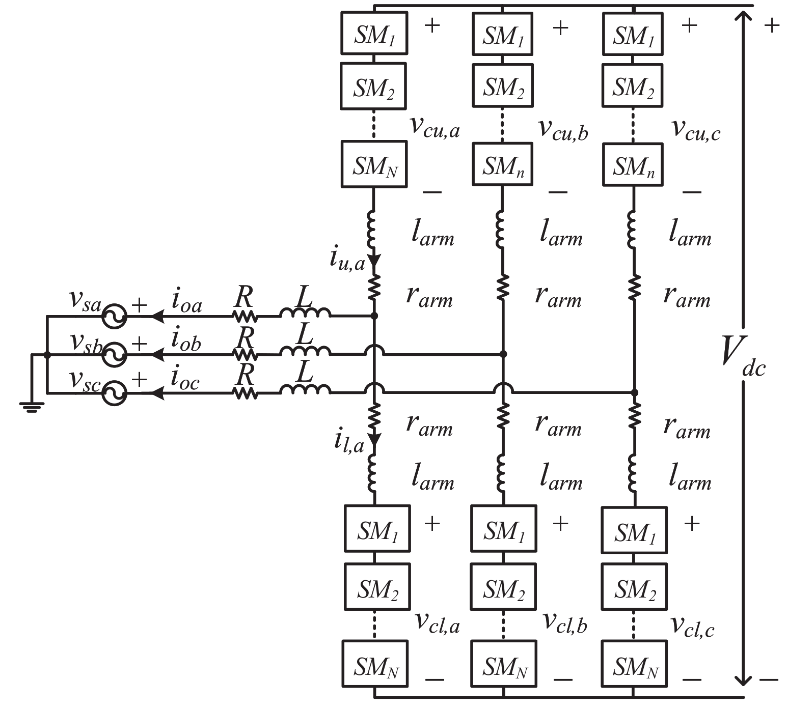
The schematic of a three-phase MMC is depicted in Figure 1. Each phase is composed of two arms connected in series between the DC terminals. Each arm consists of an arm inductor, , and N series-connected half-bridges SMs, in which each SM is equipped with a capacitor. The main function of the arm inductor is to limit fault and parasitic currents [26]. The arm resistance represents the arm power loss of each arm in the converter.
Figure 1.
The schematic circuit of MMC.
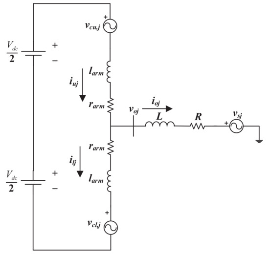
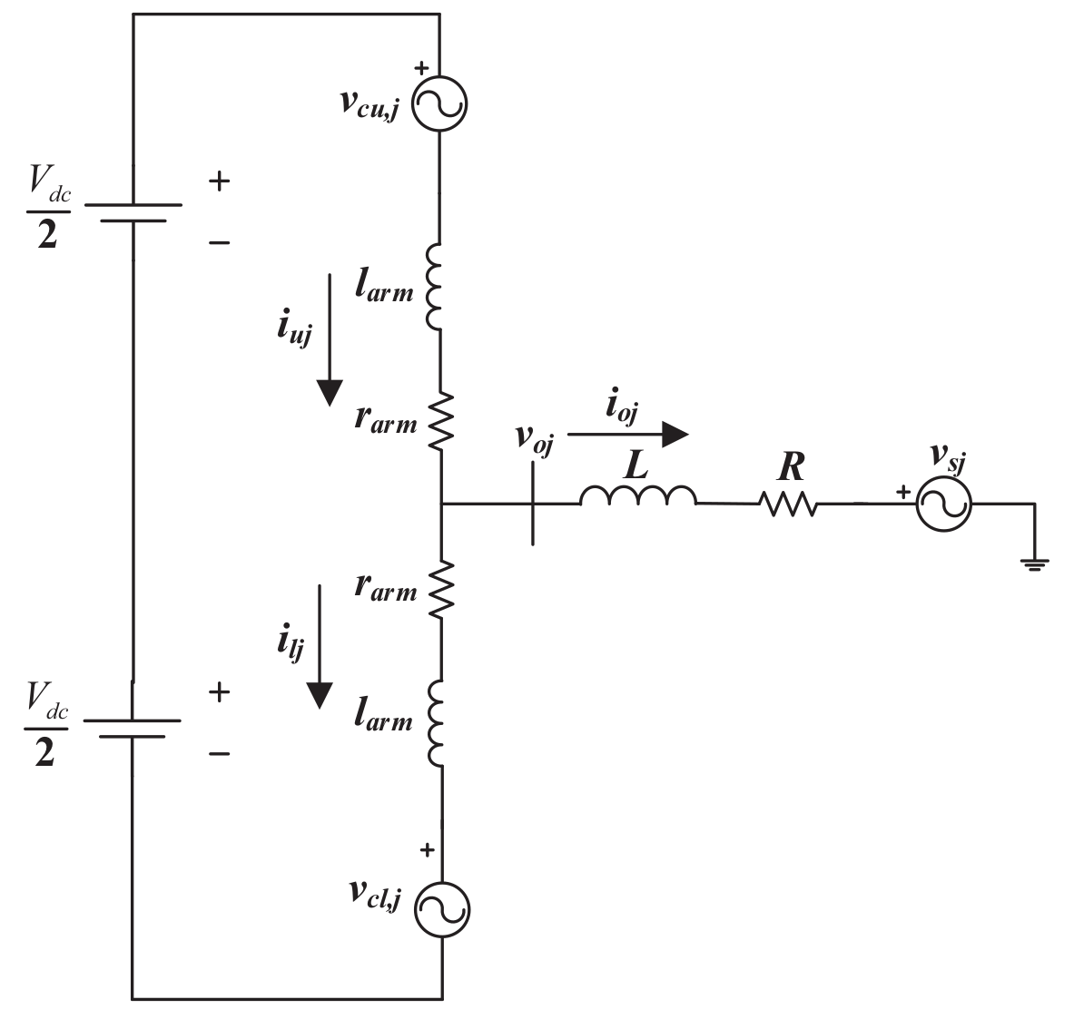
To derive the model of the MMC, one may follow the analysis presented in [11,27], and the single-phase equivalent circuit, as shown in Figure 2 is considered. The voltage sources and represent the AC voltages produced by SMs. The DC voltage is considered as constant and is denoted by in Figure 2. By applying Kirchhoff’s current law (KCL), the line current can be obtained as
where and are the upper and lower arm currents of the single phase of MMC, and . Furthermore, two sets of equations can be written for the AC side via Kirchhoff’s voltage law (KVL), as defined in (2) and (3).
Figure 2.
Single-phase equivalent circuit of MMC.
Since , (4) can be rewritten as
Without loss of generality, the single-phase model of (6) can be extended into three-phase form (7).
Applying Park transformation to (7), the dynamic of MMC in -axis can be obtained as
where and are the output current in -axis, and are the grid voltage in -axis, and and are the MMC output voltage in -axis.
2.2. Modular Multilevel Converter Control System
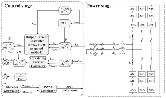
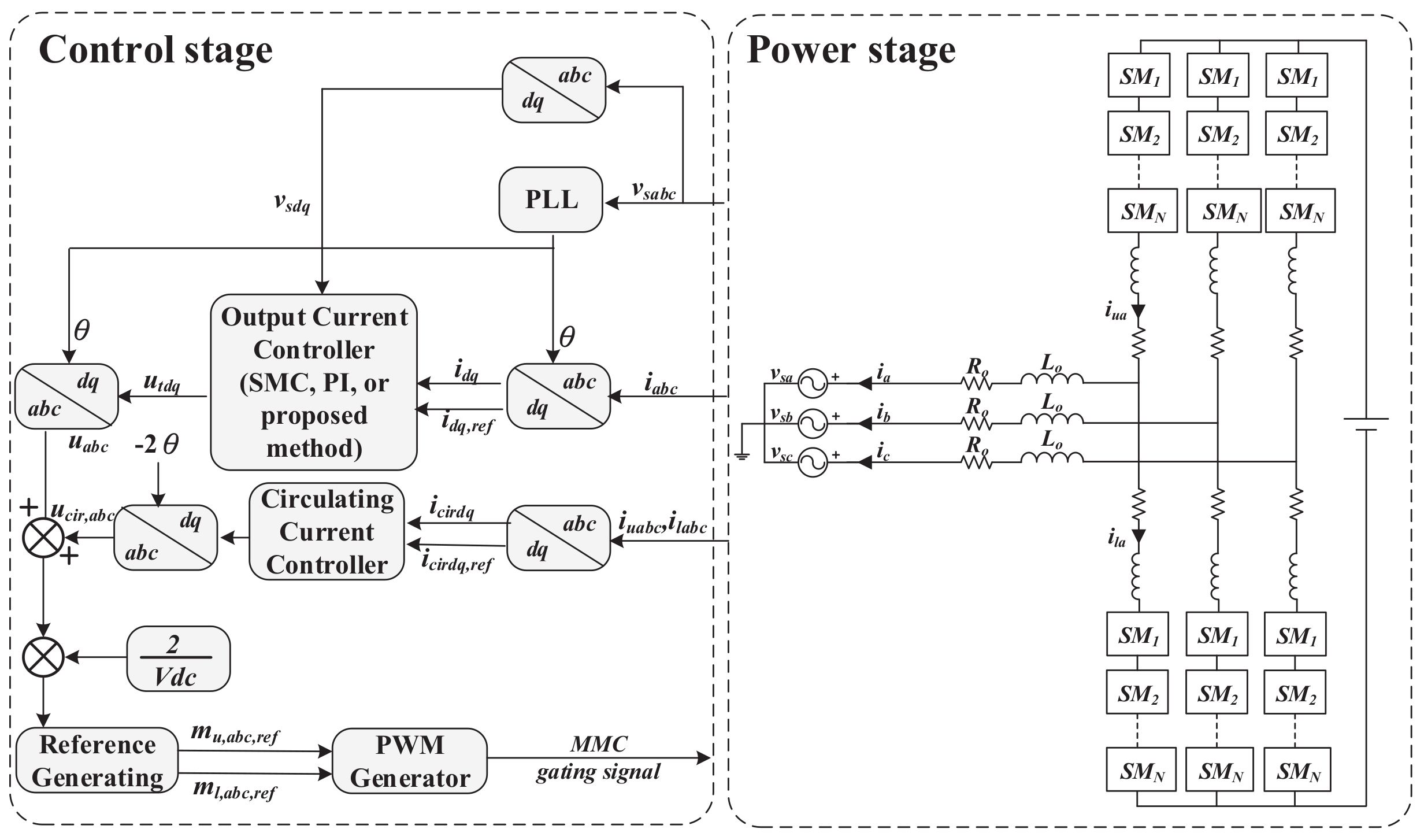
In this section, the proposed method, the conventional SMC, and PI control methods are implemented in the output current controller to compare their performances. To have a balance control of the capacitor voltages, a circulating current control (CCC) is also needed, as shown in Figure 3. In order to obtain a fair comparison for various output current control methods, the CCC control remains the same.
Figure 3.
The general control strategy for MMC.
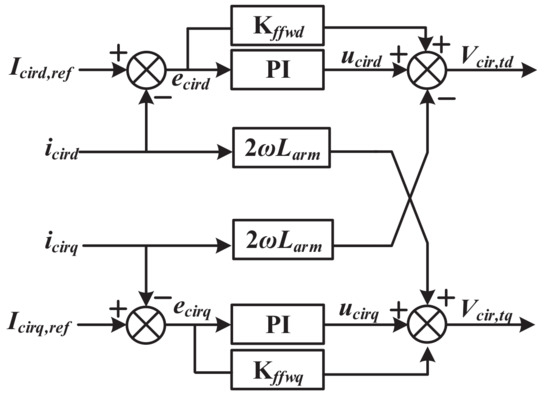
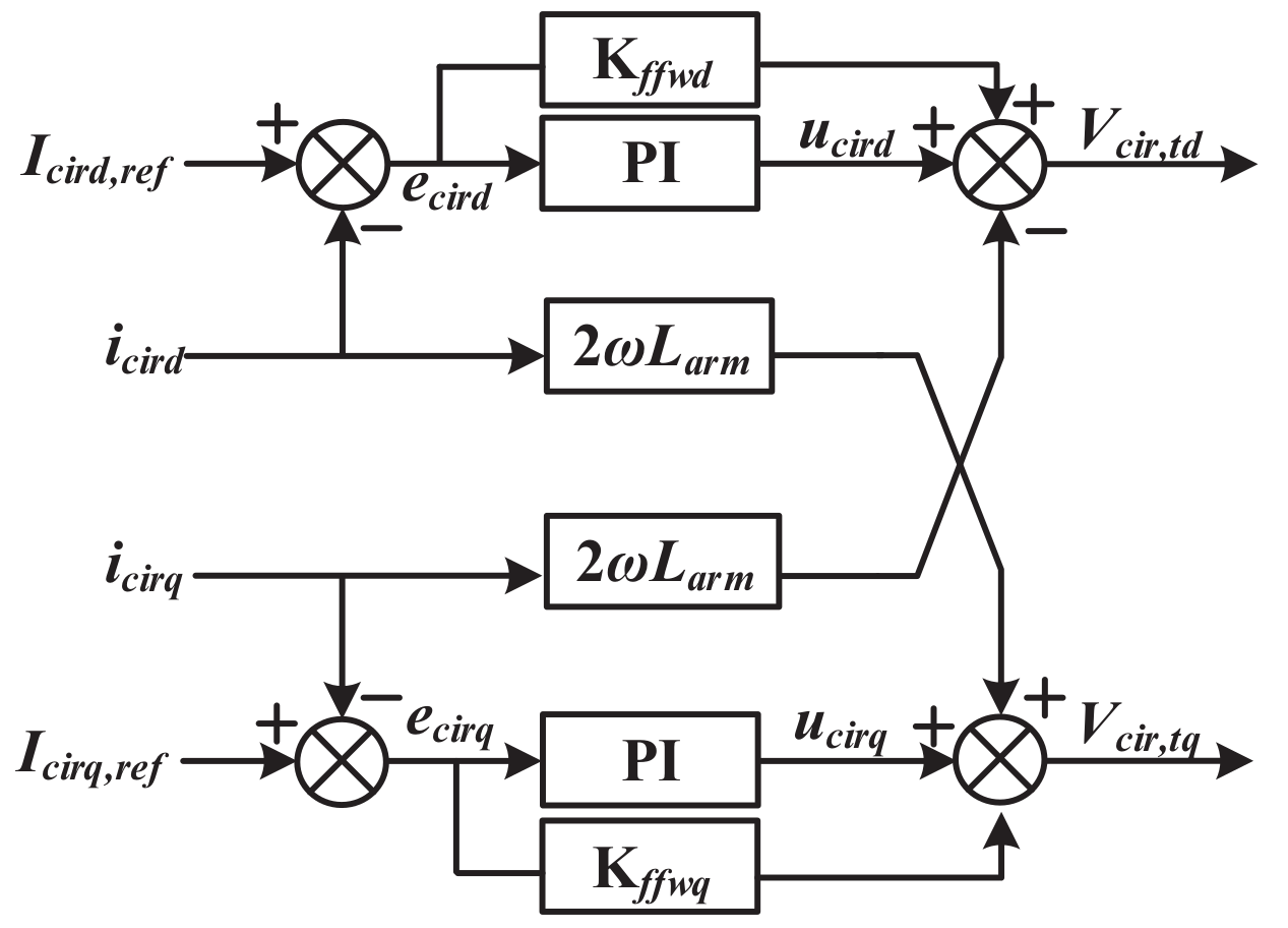
Figure 4 shows the block diagram of CCC. This is based on the control scheme proposed in [28,29], with feedforward control implemented to minimize the disturbance of the circulating current on the output current.
Figure 4.
Block diagram of the circulating current control designed in -frame.
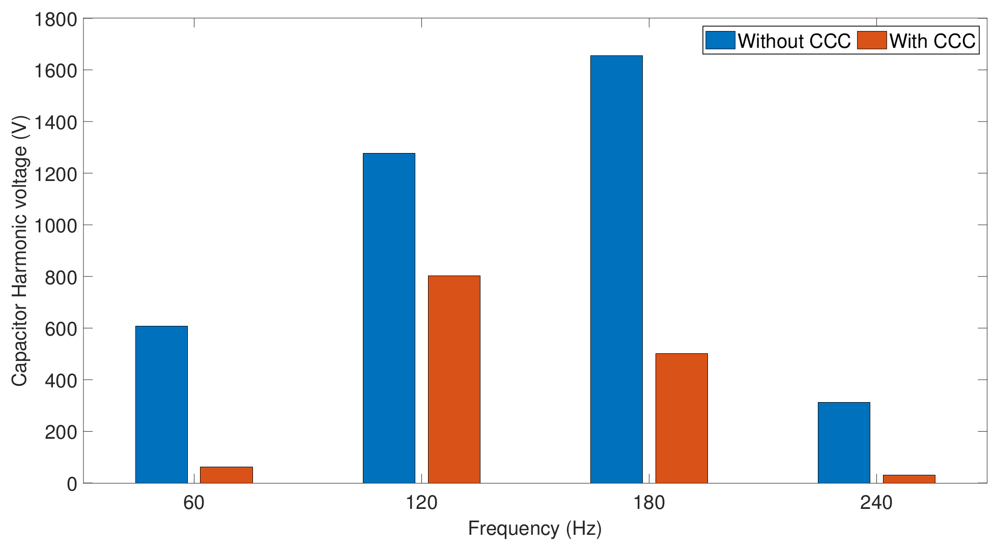
It is to be noted that the submodule capacitor voltage is closely related to the circulating current. Thus, controlling the circulating current can effectively suppress the capacitor voltage fluctuation [30]. As demonstrated in [30], such an approach can effectively suppress the capacitor voltage ripple. Figure 5 shows a comparison of the total capacitor voltage ripples in frequency domain with and without CCC. The figure clearly shows that the fundamental, second, and the third harmonic components are effectively reduced by the CCC, demonstrating that CCC together with the proposed output current control (this will be discussed in Section 2.2.3) is able to regulate the capacitor voltage.
Figure 5.
FFT analysis of the total submodule capacitor voltage.
2.2.1. PI Controller
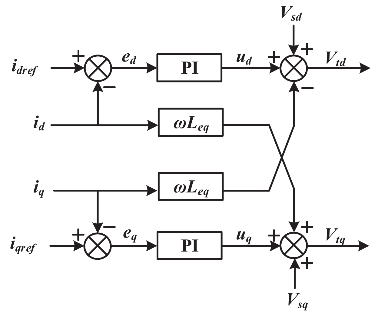
The block diagram of PI controller for regulating and can be depicted by Figure 6. The control structure is simply derived from the dynamics (8), and the decoupling term is added for allowing independent and control. The control laws for d and q-axes are obtained as
where and are the proportional and integral constants. The d- and q-axis current references are denoted by and . Substituting (10) and (11) results in
where
Figure 6.
The current controller of MMC based on PI controller.
Taking Laplace transform of (11) results in
For d-axis current,
For q-axis current,
Closed-loop transfer function can be obtained as
and
where
is integral time constant and is defined as ,
selecting , resulting in
where is the desired closed-loop time constant. Note that the right-hand side of the above equation is the desired first-order system. The first-order system is chosen as an ideal model. Thus, proportional and integral constants can be obtained as
In the paper, we select equal to 0.5 ms. Thus, and can be obtained as 2.07 and 310.35, respectively.
2.2.2. Sliding Mode Control
Consider the sliding surfaces as the function of the difference between actual and reference of current in d- and q-axis.
The equivalent control signals for d- and q-axis can be achieved by letting and , respectively, which yield
The discontinuous control signals are derived based on positive definite Lyapunov, function defined in (29):
where subscript n represents the axis, i.e., d- or q-axis.
Taking the time derivative of (29) yields
To satisfy (30) to be negative definite, the discontinuous control signal is obtained as
where is the switching gain, and . Hence, the total control laws for SMC for d- and q-axis are
2.2.3. Proposed Method
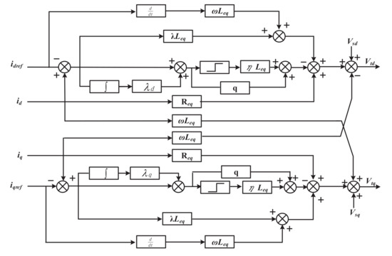
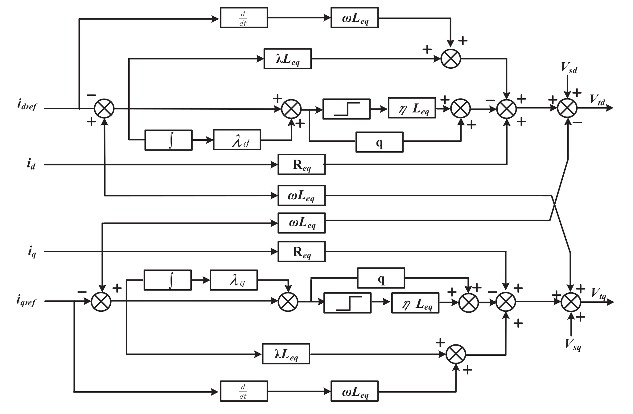
Figure 7 illustrates the block diagram of the proposed method. To enhance the control performance of conventional SMC, the PI structure is introduced for the sliding surface. The integral sliding surface is expressed as
where is defined as the difference between reference and actual value in d- and q-axis. Note that is a positive definite constant. Hence, the sliding surfaces in d- and q-axis can be represented as
Figure 7.
The current controller of MMC based on the proposed method.
Taking the time derivative of the sliding surfaces and and substituting (8) into (37) and (38), the equivalent control signals can be yielded as
Using the reaching law dynamics introduced by [31],
where and > 0. To test the stability and error convergence of SMC, a positive Lyapunov function is selected as (29).
The total control law becomes
3. Offline Simulation and Experimental Validations
In this section, the performance of the proposed method is compared with those of the PI controller and conventional SMC via offline simulation and real-time hardware-in-loop (HIL). The offline simulation is performed in PSCAD/EMTDC with 0.5 s sampling time. HIL is realized by implementing an MMC system in Real Time Digital Simulator (RTDS) and the current controller in Peripheral Component Interconnect (PCI) eXtensions for Instrumentation (PXI) from National Instruments (NI) Corporation. A 10 MW, medium-voltage MMC system was adapted from [32,33]. Table 1 lists the MMC parameters for offline and HIL simulations.
Table 1.
MMC and grid parameters.
Table 2 lists the controller parameters. For PI controller, the control parameters are obtained by using zero-pole cancellation. In addition, the carrier phase shift pulse width modulation (PWM) is employed for PWM generator.
Table 2.
Controller parameters.
3.1. Simulation Results
Three cases will be studied, and they are active and reactive currents tracking, currents regulation under short-circuit conditions, and investigation on the interaction between the output current and circulating current control to show the superior performances of the proposed method. The number of output level is selected to be seven.
3.1.1. Case 1 Active and Reactive Currents Tracking
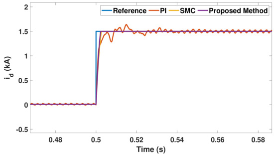
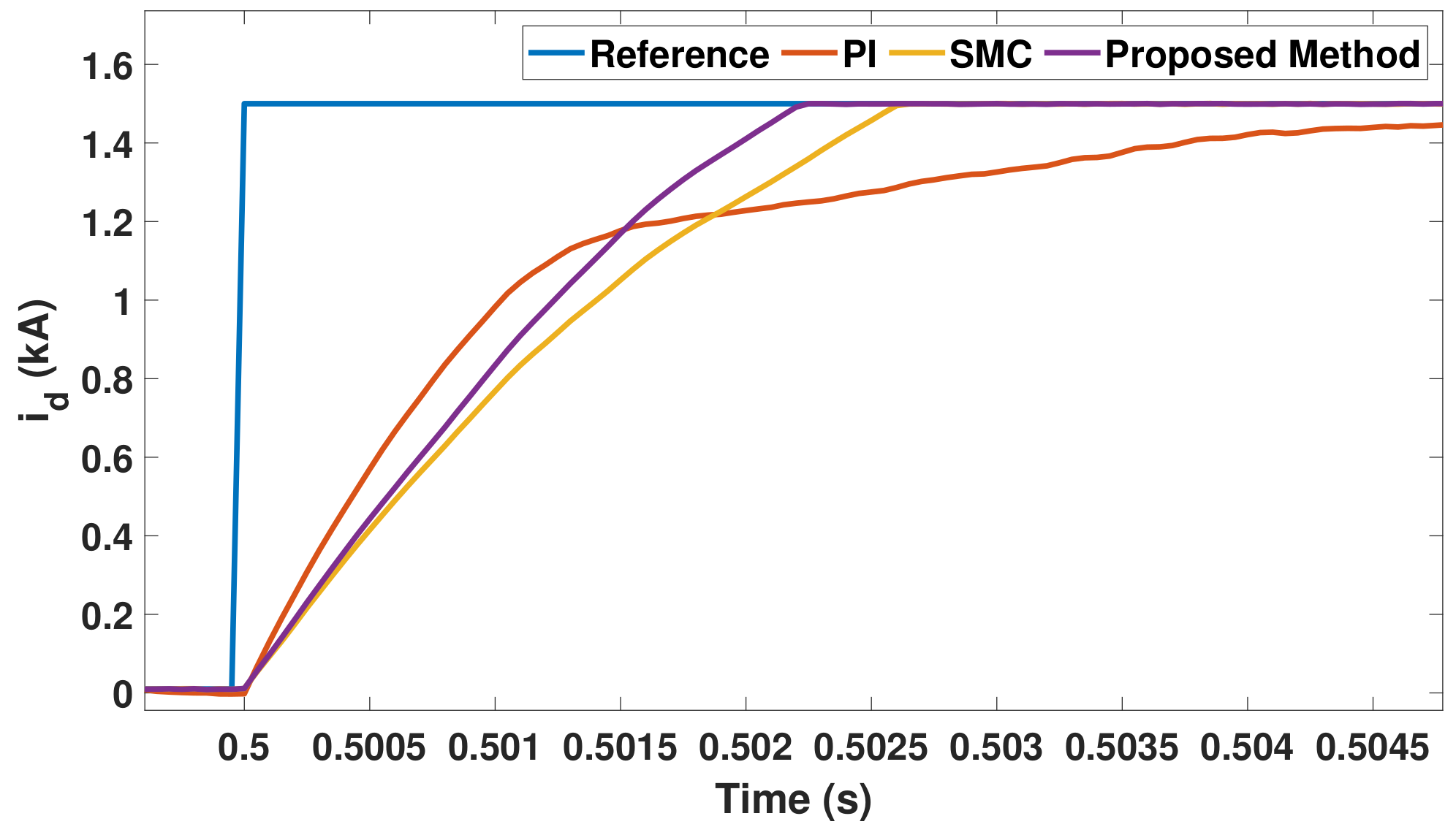
This case demonstrates the tracking performance of and . Figure 8 shows that the results for change from kA to kA at s, while is kept constant at 0 kA. As can be seen in Figure 8, the settling time of PI controller and conventional SMC in the d-axis current components requires a longer time than the proposed method.
Figure 8.
The trajectory of subjected to active current change.
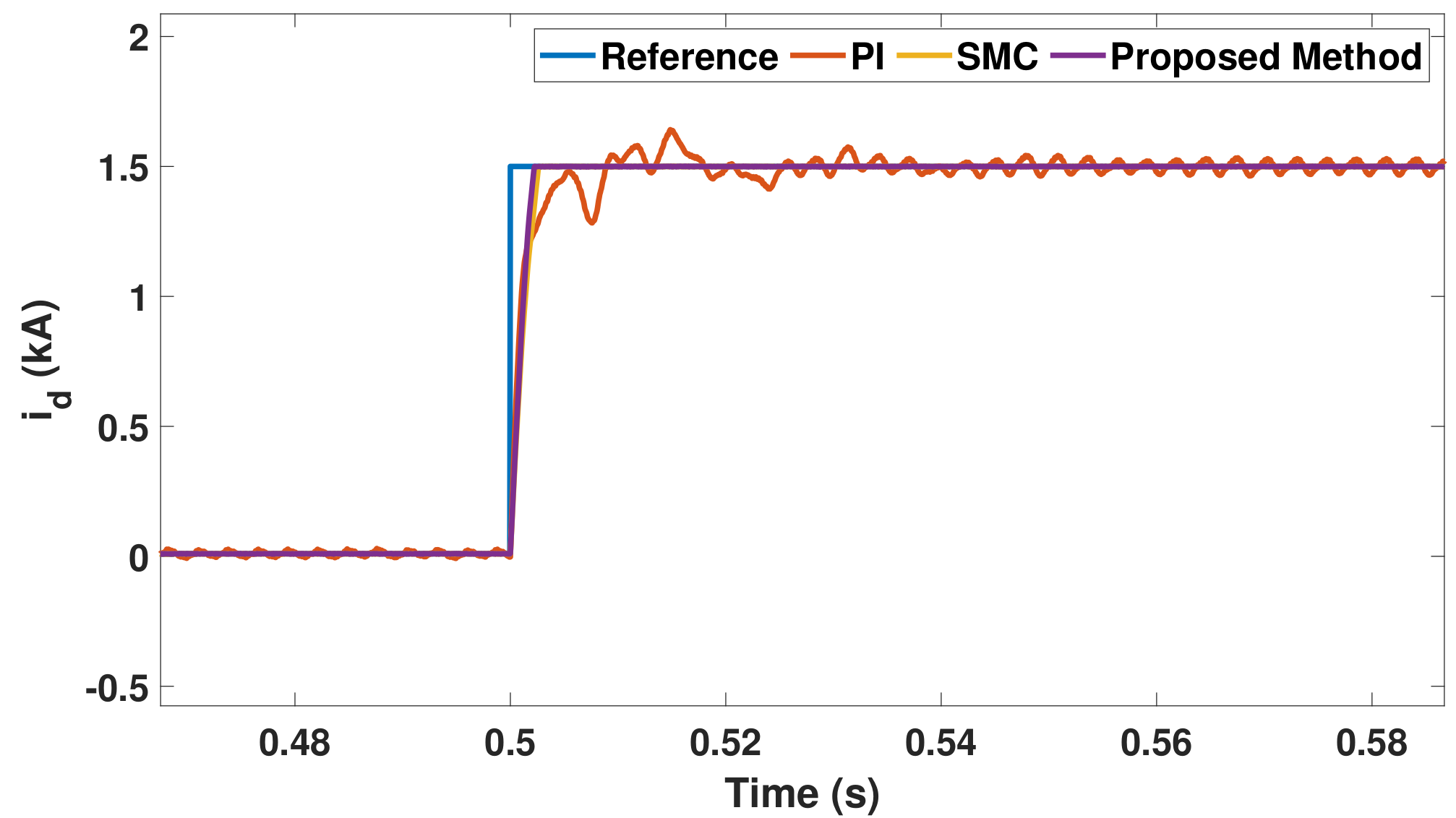
Furthermore, the proposed method produces zero overshoot and oscillations. On the other hand, PI controller generates ripples current and oscillations. Moreover, as can be seen from Figure 9, which enlarges the transient parts of Figure 8, the proposed method yields the best performance among the three controllers.
Figure 9.
Zoom-in of Figure 8.
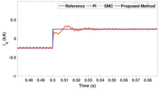
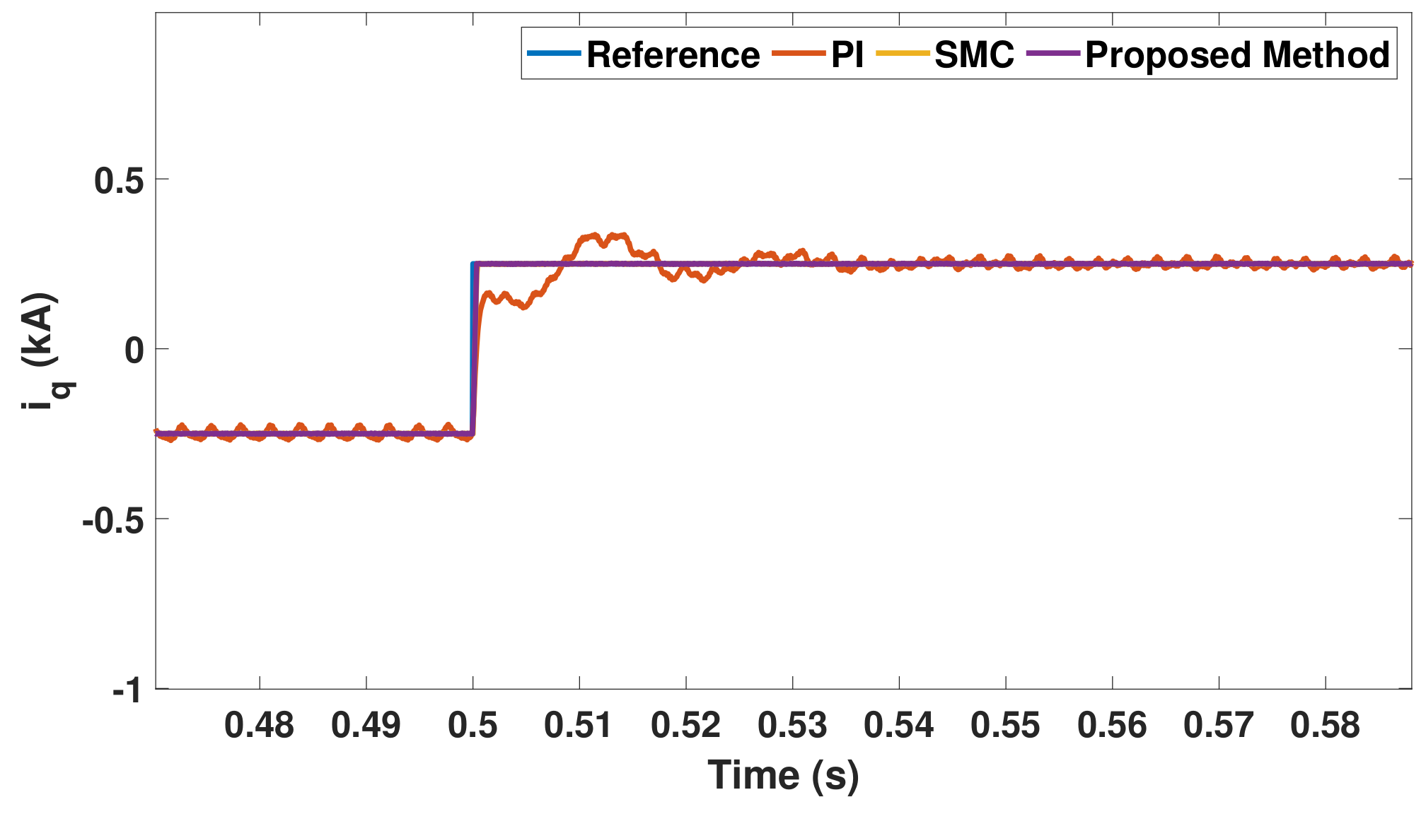
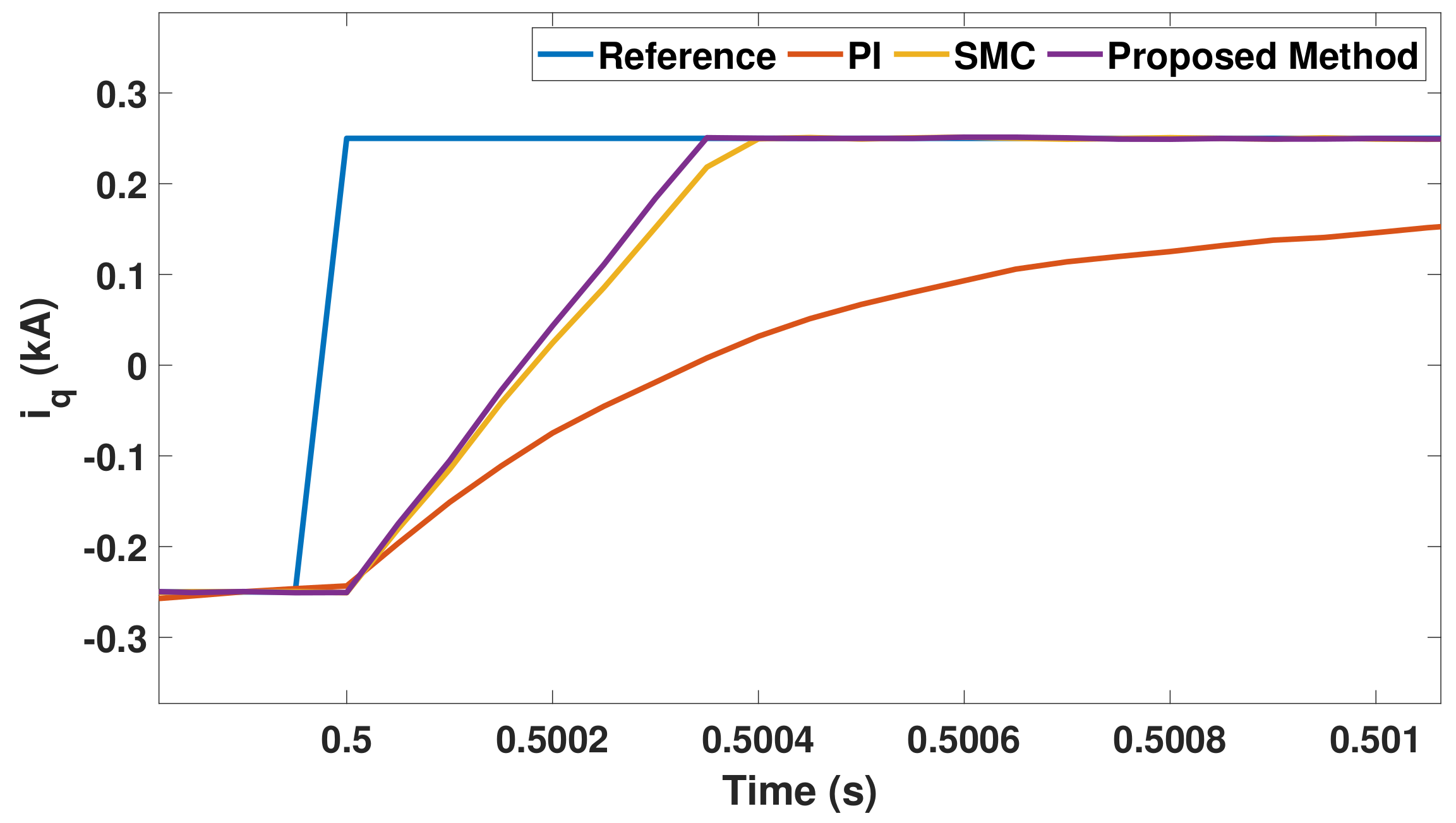
Similarly, the reactive current tracking is shown in Figure 10, where the current reference in q-axis () is stepping from kA to kA at s while the current reference in d-axis () is kept at kA. Figure 10 demonstrates the resulting step response. Although all of the controllers can track the reference well, PI controller and conventional SMC require a longer time to settle, as evident from Figure 11. Moreover, ripple current are observed for the PI controller while the conventional SMC and the proposed method exhibit freedom of current distortion. Table 3 lists the rise time (), settling time () of the output current, and steady-state errors for and , which are and , respectively. As the tables indicates, the proposed method yields the best performance.
Figure 10.
The trajectory of subjected to reactive current change.
Figure 11.
zoom-in of Figure 10.
Table 3.
Comparative table of Case 1.
3.1.2. Case 2 Current Regulations under Short Circuit Conditions
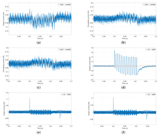
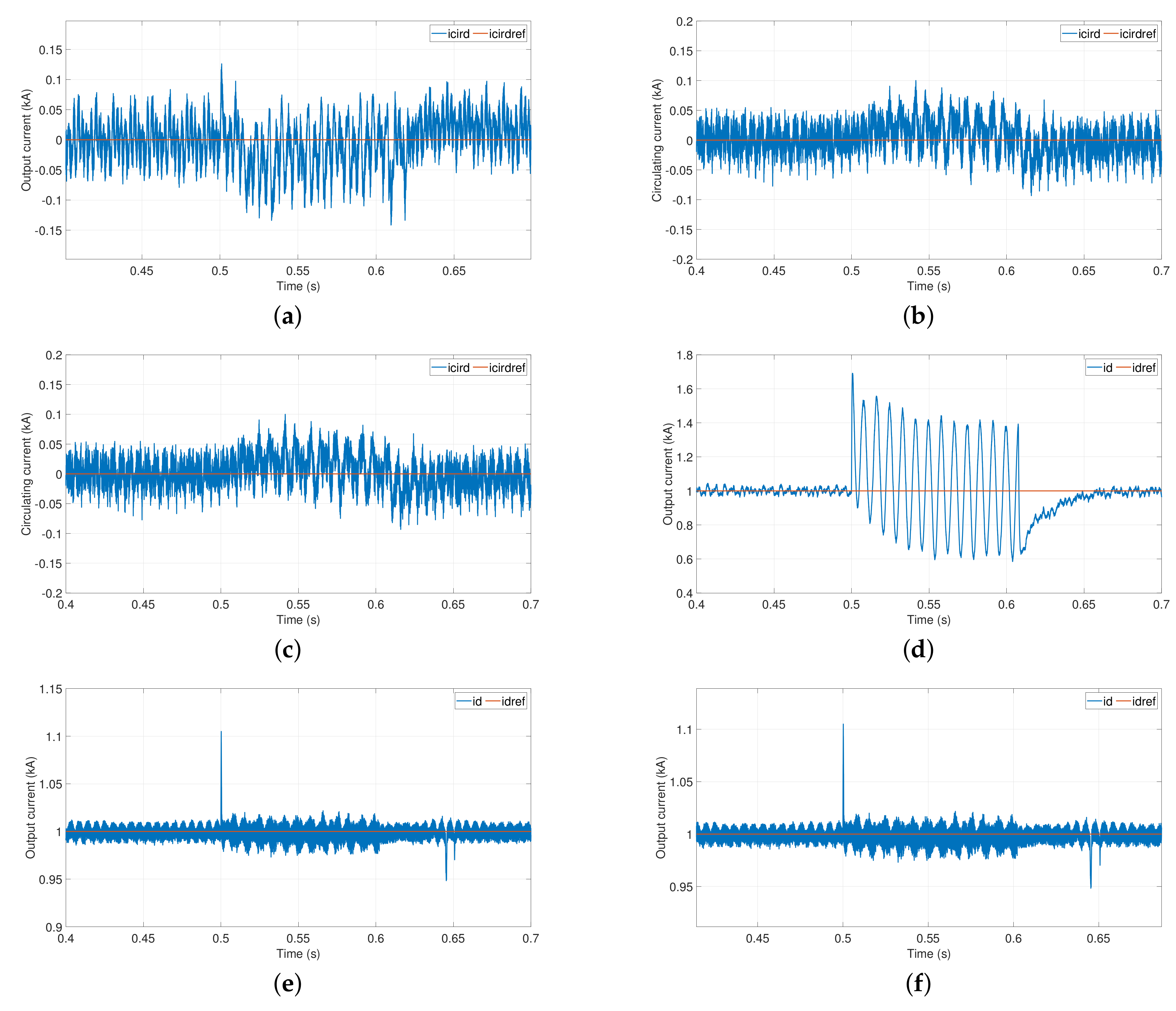
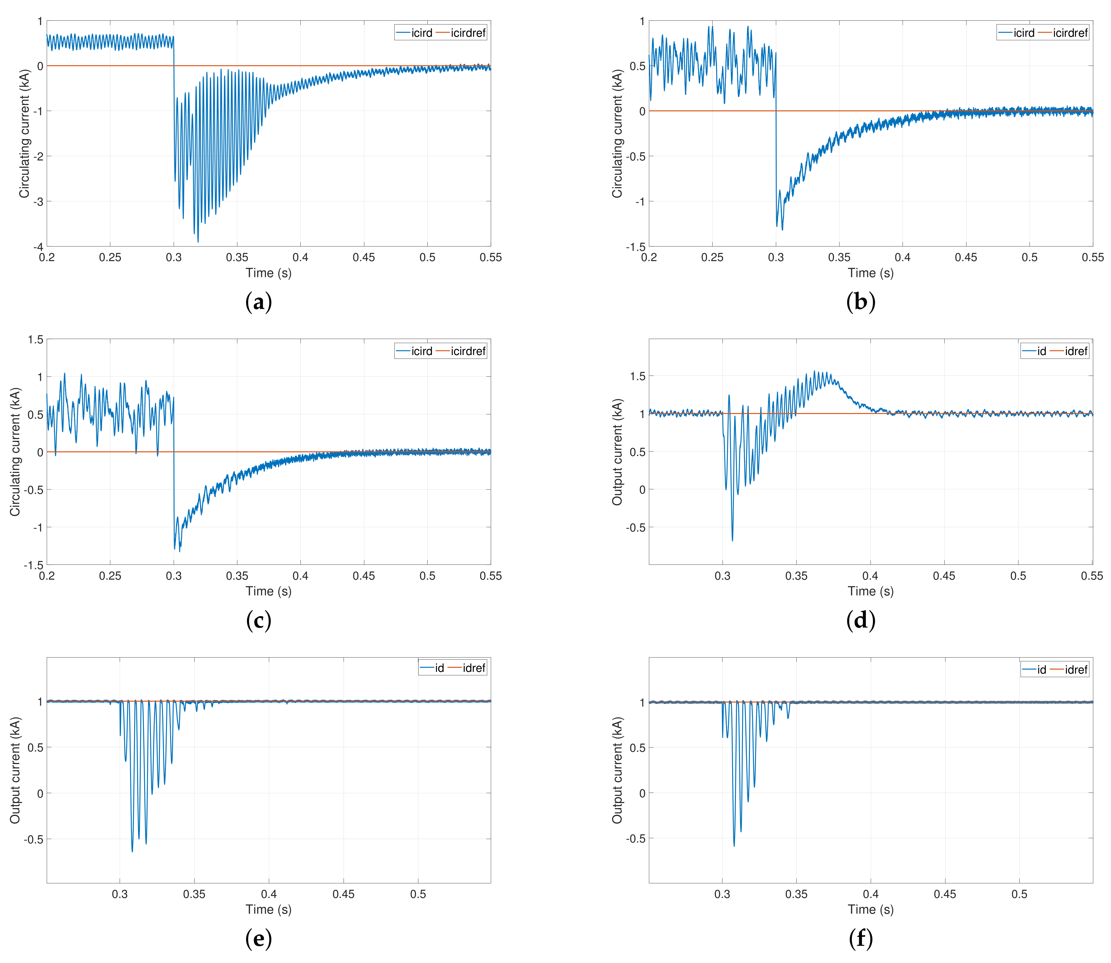
In this case, the single-phase ground fault in phase-a occurs at s, and fault resistance, , is selected to be 1 , while the reference current in d-axis is kept at 1 kA. As shown in Figure 12, the conventional SMC and the proposed method can track the reference with slight overshoot under the fault, while PI controller suffers severe oscillations before reaching steady state. The circulating currents are only slightly disturbed for the SMC and proposed method, whereas that of the PI control is affected more noticeably at s.
Figure 12.
Circulating currents in d-axis: (a) PI control, (b) SMC, (c) proposed method; the output current in d-axis: (d) PI control, (e) SMC, (f) proposed method.
3.1.3. Case 3 Investigation of the Interaction between Output and Circulating Currents Control
This case investigates the coupling effect between the circulating current control and various output current controls. The transient output currents of various control methods, caused by turning on the circulating current control at s, are compared.
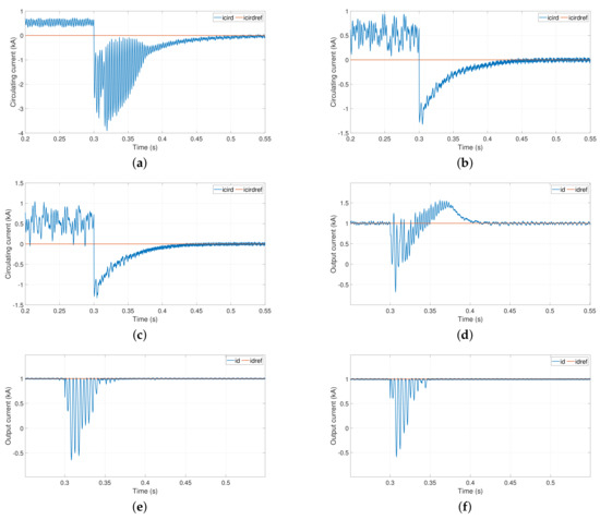
As can be seen in Figure 13, when the circulating current is turned on, the coupling effect between output current () and the circulating current () are minimum among all three methods. For instance, the maximum undershoot deviation from the steady state value () for of the proposed method is kA, while those of PI and SMC are kA and kA, respectively. The maximum undershoot deviation from the steady state value for of the proposed method is kA, whereas those of PI and SMC are kA and kA, respectively. Moreover, the maximum overshoot deviation from the steady-state value () for the PI control is kA; the other controls do not have overshoots. Table 4 lists the rise time (), settling time (), and steady-state errors () for the circulating current, and the ripple of upper () and lower capacitor voltage (). Generally, the proposed method performs the best among the three methods.
Figure 13.
Circulating currents in d-axis: (a) PI control, (b) SMC, (c) proposed method; the output current in d-axis: (d) PI control, (e) SMC, (f) proposed method.
Table 4.
Comparative table of Case 3.
3.2. Experimental Results
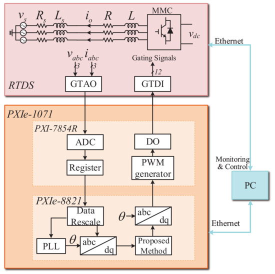
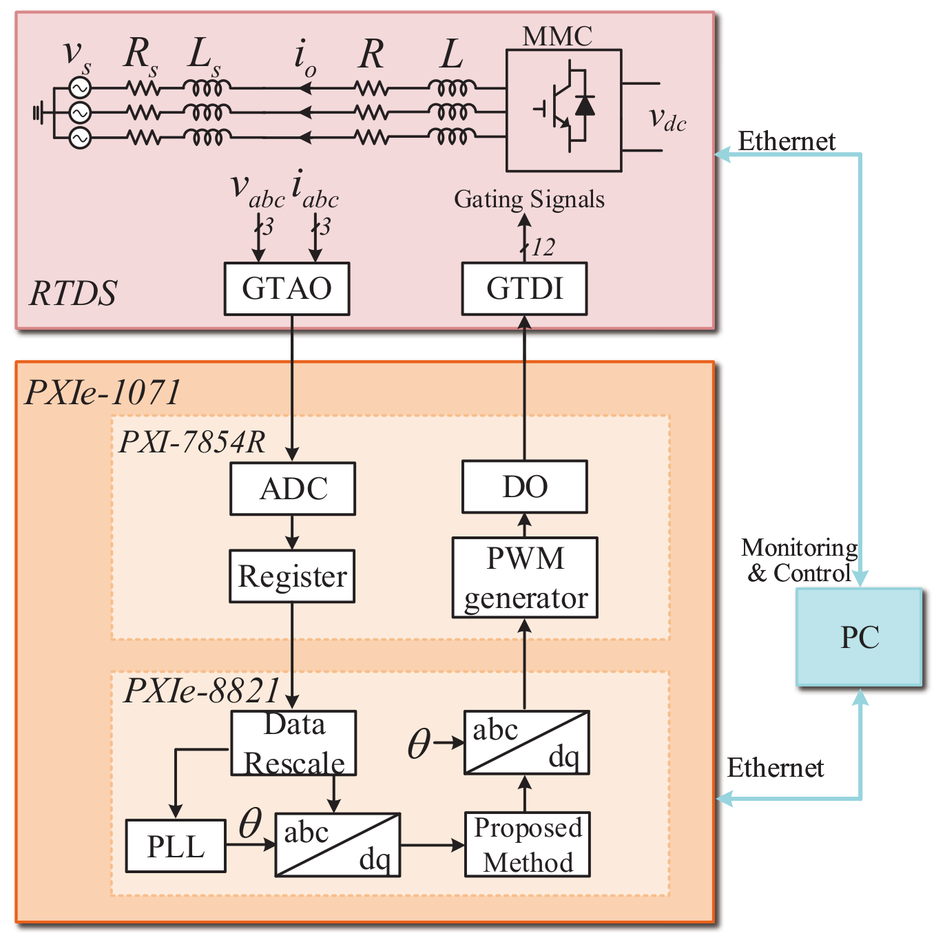
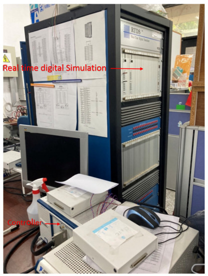
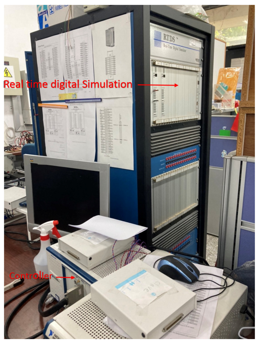
In the HIL setup, the power system, i.e., MMC, filter, and grid are realized in RTDS, while the proposed method is implemented in NI PXIe-8821. Due to the limited rack available in our RTDS, the output level for the MMC is selected to be three in the HIL simulation. The controller sends the gating signals to digital input of the RTDS via a giga-transceiver digital input (GTDI) card. The current and voltage measurements from the RTDS are sent out via a giga-transceiver analogue output (GTAO) card to the controller through an analog-to-digital converter (ADC) of PXI-7854R. The block diagram and the setup photo of the experimental setup are depicted in Figure 14 and Figure 15.
Figure 14.
Block diagram of experimental setup.
Figure 15.
The experimental test bench.
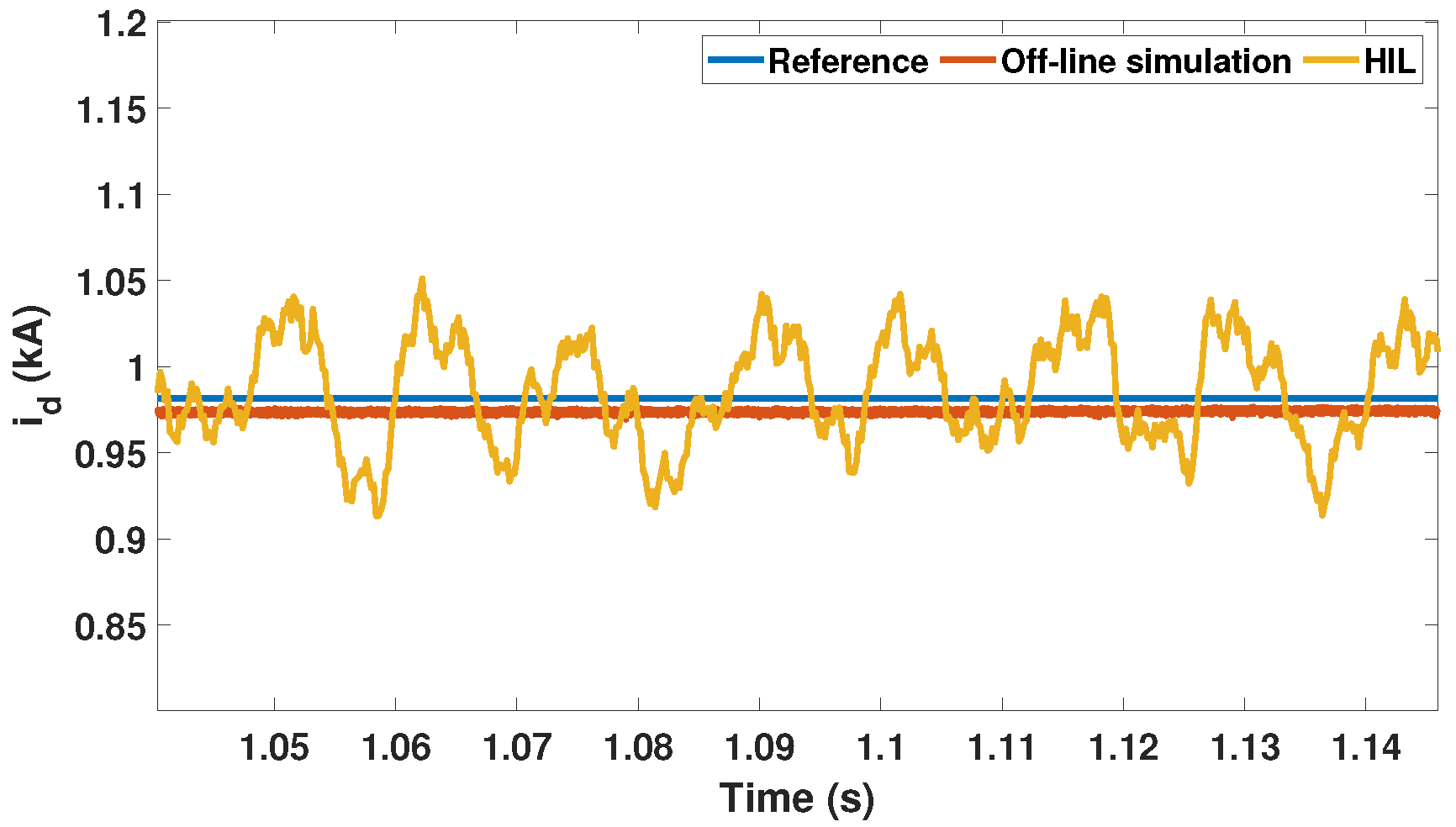
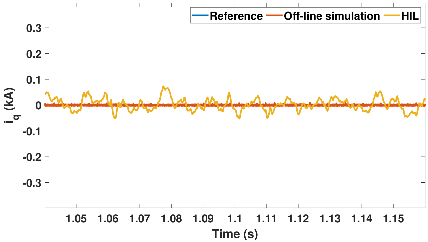
Furthermore, to verify the robustness of the proposed method, an additional test is demonstrated, i.e., grid frequency variations [34].
3.2.1. Case 1 Active and Reactive Currents Tracking
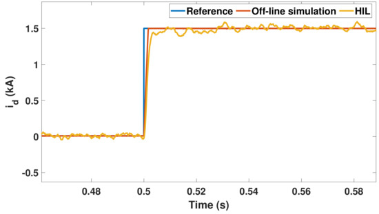
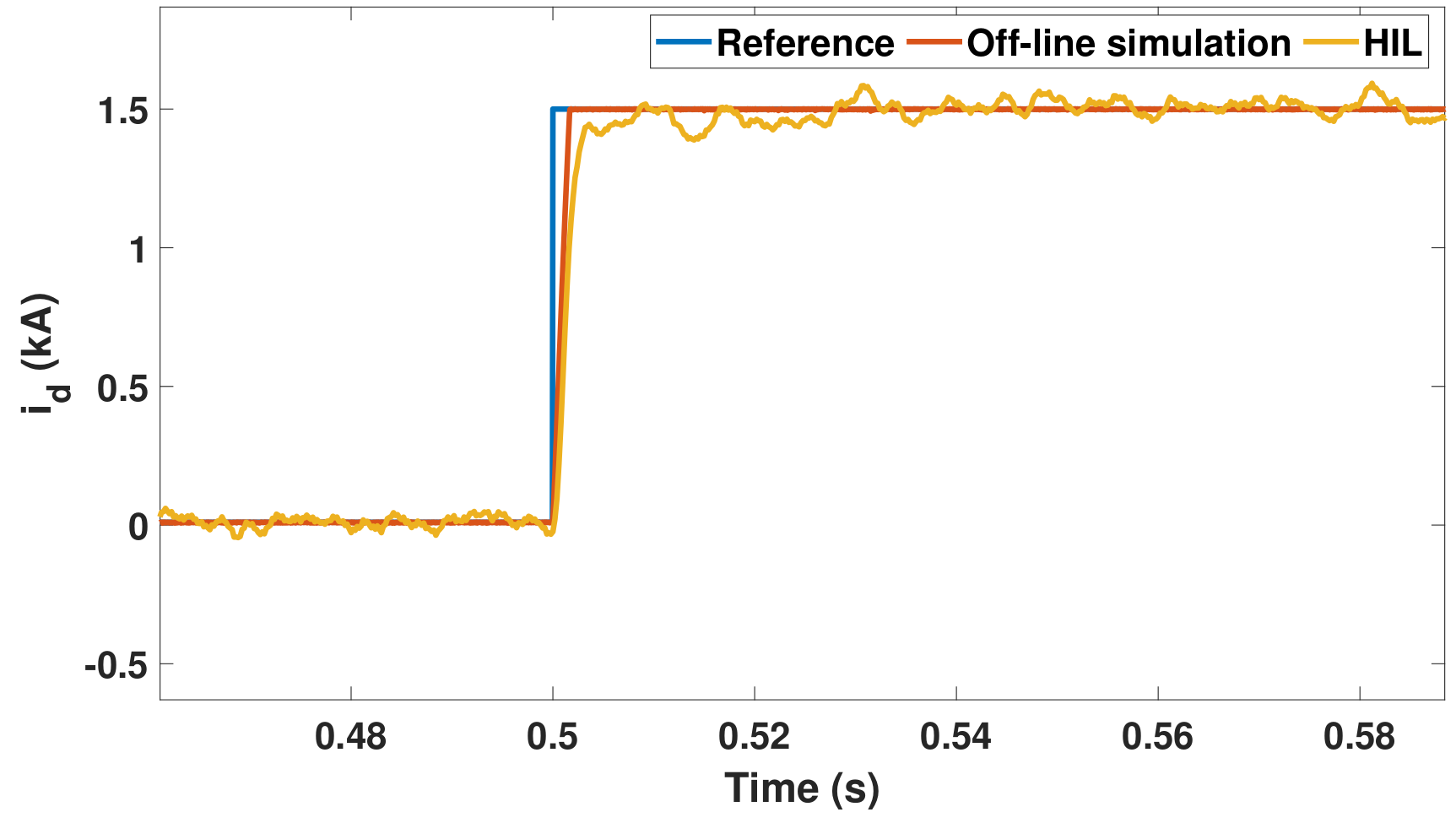
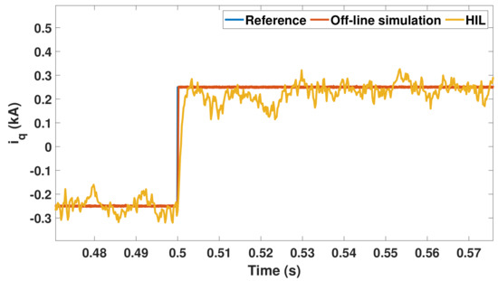
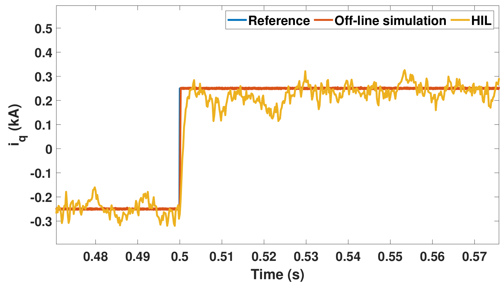
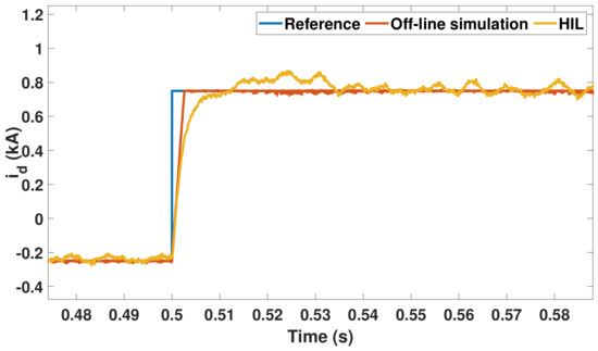
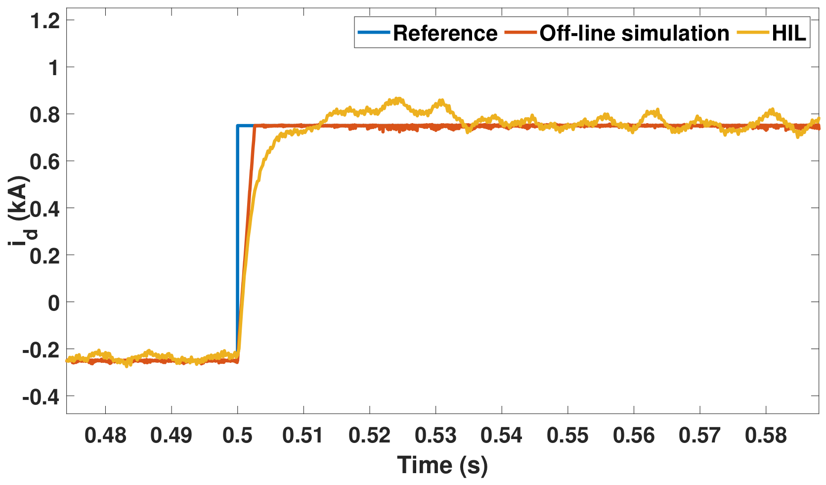
In this case, the scenario is similar to Section 3.1.1. The offline simulation and HIL simulation results are presented in Figure 16 and Figure 17. These figures validate the strong agreement between offline simulation and HIL simulation.
Figure 16.
Experimental results of using the proposed method subjected to active current change.
Figure 17.
Experimental results of using the proposed method subjected to reactive current change.
3.2.2. Case 2 Active Current Tracking under Weak Grid
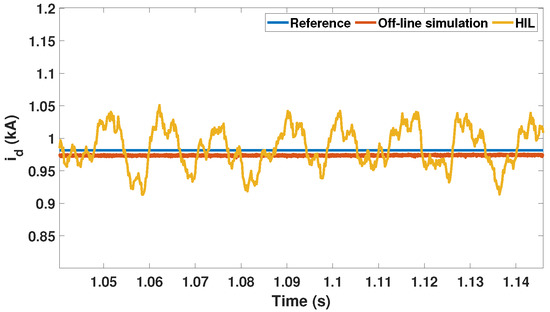
The experimental setup for this case is similar to Section 3.1.2. The comparison of offline simulation and HIL simulation results are depicted in Figure 18. As can be seen, the slight difference occurs on the settling time due to the control delay of the actual controller in an HIL setup. However, the steady-state behavior of both offline simulation and HIL simulation are similar.
Figure 18.
Experimental results of using the proposed method subjected to active current change under weak grid conditions.
3.2.3. Case 3 Currents Regulation under Grid Frequency Change
The grid frequency is reduced from 60 Hz to Hz at s. Current references, and , are kept to be constant, i.e., 1 kA and 0 kA, respectively. As can be clearly seen in Figure 19 and Figure 20, and can be still well regulated by the proposed method, even under the presence of grid frequency fluctuation. This justifies the robustness of the proposed method under grid frequency variations.
Figure 19.
Experimental results of proposed method subjected to grid frequency change: () .
Figure 20.
Experimental results of proposed method subjected to grid frequency change: () .
4. Conclusions
In this paper, an integral-based sliding surface of SMC is proposed for current control of MMC. The proposed method exhibits the superior performance among other existing methods in various conditions. All offline simulation tests clarify the capability of the proposed method compared to the PI controller and conventional SMC for producing fast transient responses, zero overshoot, and robustness to the weak grid and short-circuit conditions. Furthermore, HIL also verifies that the proposed method provides more stable and robust performance, exhibiting great agreement with offline simulation. Thus, the proposed method proves to be highly practical and functional.
Author Contributions
The research was carried out successfully with contribution from all authors. The main research idea, case scenario studies, and the design of experimental setup were contributed by B.-Y.L., R.K.S. and K.-L.L. R.K.S. and B.-Y.L. contributed to the implementation of simulation and experiment, and the analysis of these data. C.-Z.W. and B.-Y.L. partially contributed to the implementation of the experiment and simulation. B.-Y.L., C.-Z.W. and K.-L.L. mainly contributed to the preparation of the manuscript. All authors have read and agreed to the published version of the manuscript.
Funding
This work was financially supported by Connect Co. Ltd., Ministry of Science and Technology (MOST), Taiwan (under Grant No. 110-2221-E-011-158) and the Taiwan Building Technology Center from the Featured Areas Research Center Program within the framework of the Higher Education Sprout Project by the Ministry of Education in Taiwan.
Acknowledgments
The authors would like to sincerely thank the editor and anonymous reviewers for their valuable comments and suggestions, which improved the quality of the paper.
Conflicts of Interest
The authors declare no conflict of interest.
Nomenclature
| Acronym | Meaning |
| j = abc | three phases (abc) |
| , | upper and lower arm currents |
| , | upper and lower arm voltages |
| arm resistor | |
| arm inductor | |
| R | line resistor |
| L | line inductor |
| circulating current | |
| output line current | |
| output line voltage | |
| , | output current in dq-axis |
| , | output voltage in dq-axis |
| modulating signals in dq-axis | |
| equivalent resistor | |
| equivalent inductor | |
| abc/dq | quantity in three phase (abc) and dq, respectively |
| , | proportional and integral constants, respectively |
| sgn | signum function |
| error of id | |
| error of iq | |
| switching gain | |
| sliding surface gain | |
| integral sliding surface | |
| discontinuous control signals | |
| angular frequency of grid voltage | |
| rise time for the output current tracking | |
| settling time for the output current tracking | |
| steady-state error for | |
| steady-state error for | |
| rise time for circulating current tracking | |
| settling time for the circulating current tracking | |
| steady-state error for | |
| steady-state error for | |
| ripple of upper arm capacitor voltage | |
| ripple of lower arm capacitor voltage |
References
- Bull, S.R. Renewable energy today and tomorrow. Proc. IEEE 2001, 89, 1216–1226. [Google Scholar] [CrossRef] [Scilit]
- IEA. Global Energy Review. Available online: https://www.iea.org/reports/global-energy-review-2020 (accessed on 21 September 2020).
- Mohan, N.; Undeland, T.; Robbins, W. Power Electronics: Converters, Applications, and Design; John Wiley & Sons: Hoboken, NJ, USA, 2003. [Google Scholar]
- Lai, J.-S.; Peng, F.Z. Multilevel converters-a new breed of power converters. IEEE Trans. Ind. Appl. 1996, 32, 509–517. [Google Scholar]
- Busquets-Monge, S.; Rocabert, J.; Rodriguez, P.; Alepuz, S.; Bordonau, J. Multilevel Diode-Clamped Converter for Photovoltaic Generators With Independent Voltage Control of Each Solar Array. IEEE Trans. Ind. Electron. 2008, 55, 2713–2723. [Google Scholar] [CrossRef] [Scilit]
- Glinka, M.; Marquardt, R. A new AC/AC multilevel converter family. IEEE Trans. Ind. Electron. 2005, 52, 662–669. [Google Scholar] [CrossRef] [Scilit]
- Du, S.; Wu, B.; Zargari, N. Delta-Channel Modular Multilevel Converter for a Variable-Speed Motor Drive Application. IEEE Trans. Ind. Electron. 2018, 65, 6131–6139. [Google Scholar] [CrossRef] [Scilit]
- Xu, F.; Xu, Z.; Zheng, H.; Tang, G.; Xue, Y. A Tripole HVDC System Based on Modular Multilevel Converters. IEEE Trans. Power Deliv. 2014, 29, 1683–1691. [Google Scholar] [CrossRef] [Scilit]
- Yang, J.; Song, P.; Xu, Z.; Xiao, H.; Cai, H.; Xie, Z. Small-signal model of vector current-controlled MMC-UPFC. IET Gener. Transm. Distrib. 2019, 13, 4180–4189. [Google Scholar] [CrossRef] [Scilit]
- Yu, X.; Wei, Y.; Jiang, Q. STATCOM Operation Scheme of the CDSM-MMC During a Pole-to-Pole DC Fault. IEEE Trans. Power Deliv. 2016, 31, 1150–1159. [Google Scholar] [CrossRef] [Scilit]
- Du, S.; Dekka, A.; Wu, B.; Zargari, N. Review of High-Power Converters. In Modular Multilevel Converters: Analysis, Control, and Applications; Wiley-IEEE Press: Hoboken, NJ, USA, 2018; pp. 1–36. [Google Scholar]
- Sher, H.A.; Addoweesh, K.E.; Al-Haddad, K. An Efficient and Cost-Effective Hybrid MPPT Method for a Photovoltaic Flyback Microinverter. IEEE Trans. Sustain. Energy 2018, 9, 1137–1144. [Google Scholar] [CrossRef] [Scilit]
- Alotaibi, S.; Darwish, A. Modular Multilevel Converters for Large-Scale Grid-Connected Photovoltaic Systems: A Review. Energies 2021, 14, 6213. [Google Scholar] [CrossRef] [Scilit]
- Wang, W.; Beddard, A.; Barnes, M.; Marjanovic, O. Analysis of Active Power Control for VSC-HVDC. IEEE Trans. Power Deliv. 2014, 29, 1978–1988. [Google Scholar] [CrossRef] [Scilit]
- Du, S.; Dekka, A.; Wu, B.; Zargari, N. Role of Modular Multilevel Converters in The Power System. In Modular Multilevel Converters: Analysis, Control, and Applications; Wiley-IEEE Press: Hoboken, NJ, USA, 2018; pp. 271–309. [Google Scholar]
- Yang, S.; Tang, Y.; Wang, P. Distributed Control for a Modular Multilevel Converter. IEEE Trans. Power Electron. 2018, 33, 5578–5591. [Google Scholar] [CrossRef] [Scilit]
- Teodorescu, R.; Blaabjerg, F.; Liserre, M.; Loh, P.C. Proportional-resonant controllers and filters for grid-connected voltage-source converters. IEE Proc. Electr. Power Appl. 2006, 153, 750–762. [Google Scholar] [CrossRef] [Scilit]
- Qin, J.; Saeedifard, M. Predictive Control of a Modular Multilevel Converter for a Back-to-Back HVDC System. IEEE Trans. Power Deliv. 2012, 27, 1538–1547. [Google Scholar]
- Vatani, M.; Bahrani, B.; Saeedifard, M.; Hovd, M. Indirect Finite Control Set Model Predictive Control of Modular Multilevel Converters. IEEE Trans. Smart Grid 2015, 6, 1520–1529. [Google Scholar] [CrossRef] [Scilit]
- Montoya-Acevedo, D.A.; Buitrago-Herrera, J.C.; Escobar-Mejia, A. Feedback linearization applicable to the state-space modelling of an HVDC terminal based on modular multilevel converteter. In Proceedings of the 2017 IEEE Energy Conversion Congress and Exposition (ECCE), Cincinnati, OH, USA, 1–5 October 2017; pp. 2666–2672. [Google Scholar]
- Utkin, V.; Lee, H. Chattering Problem in Sliding Mode Control Systems. In Proceedings of the International Workshop on Variable Structure Systems (VSS’06), Alghero, Sardinia, 5–7 June 2006; pp. 346–350. [Google Scholar]
- Tanelli, M.; Ferrara, A. Enhancing Robustness and Performance via Switched Second Order Sliding Mode Control. IEEE Trans. Autom. Control 2013, 58, 962–974. [Google Scholar] [CrossRef] [Scilit]
- Yang, Q.; Saeedifard, M.; Perez, M.A. Sliding Mode Control of the Modular Multilevel Converter. IEEE Trans. Ind. Electron. 2019, 66, 887–897. [Google Scholar] [CrossRef] [Scilit]
- Ishfaq, M.; Uddin, W.; Zeb, K.; Islam, S.U.; Hussain, S.; Khan, I.; Kim, H.J. Active and Reactive Power Control of Modular Multilevel Converter Using Sliding Mode Controller. In Proceedings of the 2019 2nd International Conference on Computing, Mathematics and Engineering Technologies (iCoMET), Sukkur, Pakistan, 30–31 January 2019; pp. 1–5. [Google Scholar]
- Uddin, W.; Zeb, K.; Adil Khan, M.; Ishfaq, M.; Khan, I.; Islam, S.U.; Kim, H.J.; Park, G.S.; Lee, C. Control of Output and Circulating Current of Modular Multilevel Converter Using a Sliding Mode Approach. Energies 2019, 12, 4084. [Google Scholar] [CrossRef] [Scilit]
- Harnefors, L.; Antonopoulos, A.; Norrga, S.; Angquist, L.; Nee, H. Dynamic Analysis of Modular Multilevel Converters. IEEE Trans. Ind. Electron. 2013, 60, 2526–2537. [Google Scholar] [CrossRef] [Scilit]
- Wu, R.; Dewan, S.B.; Slemon, G.R. A PWM AC-to-DC converter with fixed switching frequency. IEEE Trans. Ind. Appl. 1990, 26, 880–885. [Google Scholar] [CrossRef]
- Freytes, J.; Bergna, G.; Suul, J.A.; D’Arco, S.; Gruson, F.; Colas, F.; Saad, H.; Guillaud, X. Improving Small-Signal Stability of an MMC With CCSC by Control of the Internally Stored Energy. IEEE Trans. Power Deliv. 2018, 33, 429–439. [Google Scholar] [CrossRef] [Scilit]
- Tu, Q.; Xu, Z.; Xu, L. Reduced Switching-Frequency Modulation and Circulating Current Suppression for Modular Multilevel Converters. IEEE Trans. Power Deliv. 2011, 26, 2009–2017. [Google Scholar] [CrossRef] [Scilit]
- Yang, Z.; Zhang, K.; Li, X.; Li, Y.; Song, P. A Control Strategy for Suppressing Submodule Capacitor Voltage Fluctuation of MMC Based on Circulating Current Voltage Drop Balance. IEEE Access 2021, 9, 9130–9141. [Google Scholar] [CrossRef] [Scilit]
- Gao, W.; Wang, Y.; Homaifa, A. Discrete-time variable structure control systems. IEEE Trans. Ind. Electron. 1995, 42, 117–122. [Google Scholar] [CrossRef] [Scilit]
- Liu, Y.; Xi, Z.; Liang, Z.; Song, W.; Bhattacharya, S.; Huang, A.; Langston, J.; Steurer, M.; Litzenberger, W.; Anderson, L.; et al. Controller hardware-in-the-loop validation for a 10 MVA ETO-based STATCOM for wind farm application. In Proceedings of the 2009 IEEE Energy Conversion Congress and Exposition, San Jose, CA, USA, 20–24 September 2009; pp. 1398–1403. [Google Scholar] [CrossRef] [Scilit]
- Lo, Y.H.; Chen, Y.C.; Lian, K.L.; Karimi, H.; Wang, C.Z. An Iterative Control Method for Voltage Source Converters to Eliminate Uncharacteristic Harmonics Under Unbalanced Grid Voltages for High-Power Applications. IEEE Trans. Sustain. Energy 2019, 10, 1419–1429. [Google Scholar] [CrossRef] [Scilit]
- Gui, Y.; Kim, C.; Chung, C.C.; Guerrero, J.M.; Guan, Y.; Vasquez, J.C. Improved Direct Power Control for Grid-Connected Voltage Source Converters. IEEE Trans. Ind. Electron. 2018, 65, 8041–8051. [Google Scholar] [CrossRef] [Scilit]


Publisher’s Note: MDPI stays neutral with regard to jurisdictional claims in published maps and institutional affiliations. |
© 2022 by the authors. Licensee MDPI, Basel, Switzerland. This article is an open access article distributed under the terms and conditions of the Creative Commons Attribution (CC BY) license (https://creativecommons.org/licenses/by/4.0/).