Article

A Type-2 Fuzzy Controller for Floating Tension-Leg Platforms in Wind Turbines

1
Vibrations and Acoustics Laboratory (VAL), Mechanical Engineering Department, Ozyegin University, Istanbul 34794, Turkey
2
Department of Computer Science and Artificial Intelligence, College of Computer Science and Engineering, University of Jeddah, Jeddah 21959, Saudi Arabia
3
Department of Medical Equipment Technology, College of Applied Medical Science, Majmaah University, Majmaah 11952, Saudi Arabia
4
Department of Physics, College of Arts, Fezzan University, Traghen 71340, Libya
5
Department of Chemistry, Faculty of Science, Taif University, P.O. Box 11099, Taif 21944, Saudi Arabia
6
Institute of Research and Development, Duy Tan University, Da Nang 550000, Vietnam
7
School of Engineering and Technology, Duy Tan University, Da Nang 550000, Vietnam
8
Future Technology Research Center, National Yunlin University of Science and Technology, Douliu 64002, Taiwan
9
Department of Electrical and Computer Engineering, University of Louisiana at Lafayette, Lafayette, LA 70504, USA
*
Authors to whom correspondence should be addressed.
Energies 2022, 15(5), 1705; https://doi.org/10.3390/en15051705
Submission received: 28 January 2022 / Revised: 18 February 2022 / Accepted: 19 February 2022 / Published: 24 February 2022

Abstract

:
This paper proposes a type-2 fuzzy controller for floating tension-leg platforms in wind turbines. Its main objective is to stabilize and control offshore floating wind turbines exposed to oscillating motions. The proposed approach assumes that the dynamics of all units are completely unknown. The latter are approximated using the proposed Sugeno-based type-2 fuzzy approach. A nonlinear Kalman-based algorithm is developed for parameter optimization, and linear matrix inequalities are derived to analyze the system’s stability. For the fuzzy system, both rules and membership functions are optimized. Additionally, in the designed approach, the estimation error of the type-2 fuzzy approach is also considered in the stability analysis. The effectiveness and performance of the proposed approach is assessed using a simulation study of a tension leg platform subject to various disturbance modes.

1. Introduction

Wind energy has been one of the fastest growing renewable energy sources in the world. The global onshore and offshore installed wind-generation capacity has seen an annual increase of 14% on average, reaching 743 GW in 2020 [1]. The size of the wind turbines has seen a steady increase over the years as well. This has led to increased interest in installing wind turbines and floating wind turbines offshore. Since offshore wind speeds tend to be faster and steadier than those on land, offshore wind farms can be made larger and generate more energy than those onshore with less physical impact [2,3].
Floating WTs can be installed in three ways, including floating foundation, tension leg platform (TLP), and barge, the stability of which requires special techniques. The first technique is related to floating rigs, the weight of which becomes heavy by accumulating sand in the lower part of the rig. Then, strong cables are connected to the end of the rig to attach it to the seabed. The second technique is associated with TLP rigs, which achieve static stability using tensile restraining cables and floating force resulting from the presence of a tank at the bottom of the tower. The third technique is specific to the rigs that are placed on floating platforms connected to the seabed by cables. The TLP connection has various advantages. These platforms are significantly more secure than fixed platforms in earthquake-prone areas. Moreover, the cost of installing TLP rigs is lower than that of the protected structures, especially at the deep seabed. TLP systems can be easily deployed and transported depending on local conditions [4,5].
The limitations of conventional design methods, including low attenuation of structural systems and materials for absorbing the energy of dynamic loads as well as having constant dynamic properties incompatible with external dynamic loads, have led to the development of modern methods in order to design durable structures and reduce damage to rigs. Structural control systems have been developed to reduce unwanted vibrations applied to the main system for any reason [6,7].
Since the collision of turbulent sea waves with these platforms causes unwanted oscillatory motion and spatial instability of turbine rigs, designing suitable controllers to mitigate this spatial instability is of great importance. Several researchers have proposed methods for controlling and stabilizing TLP systems. Chen et al. investigated the stability of TLP systems using Lyapunov’s stability method and a fuzzy logic system (FLS), and designed a controller considering a constant delay [8,9]. Amini et al. examined the control of TLP systems using linear-matrix inequalities (LMI) and a type-1 fuzzy controller considering uncertainty, delay and disturbance [10,11]. The adaptive FLSs are used in various uncertain problems [12,13]; however, for TLP, FLS-based controllers have been rarely designed.
Designing an appropriate controller for nonlinear systems in the presence of uncertainties is among the most important topics in control design. Methods developed based on Lyapunov stability and neural networks as well as FLS controllers have very good performance in the presence of noise and uncertainties [14]. Applying fuzzy logic to the sliding surface can increase the desired signal tracking accuracy, reduce chattering and minimize the control effort [15]. Due to the widespread use of fuzzy logic-based systems in various fields of engineering, developing fuzzy systems has attracted the attention of many researchers. Interval type-2 (T2) FLS, which includes membership functions (MFs) of fuzzy intervals, was proposed and proved to be more resistant to uncertainties than type-1 fuzzy logic. Interval T2FLS has many applications, the most recent of which includes fault detection [16,17], robotic control [18], medical diagnose [19], prediction problems [20], risk diagnosis [21] and financial investment [22]. The general T2FLS was introduced to improve IT2FLS performance in various applications. In [23], the general type-2 fuzzy set with optimal MFs was examined for frequency tuning in AC microgrids (MGs). In [24], a GT2FLS was used for the edge detection problem. A general type-2 fuzzy classifier (GT2FC) was proposed by Ontiveros-Robles and Melin [25], for the diagnosis problems. Shukla and Muhuri [26] proposed a general type 2 fuzzy decision-making approach (GT2DM). They applied this method to travel time selection. Results revealed that GT2DM outperforms interval type-2 (IT2DM) in decision-making.
Type-3 (T3) FLS was introduced to improve the behavior of GT2FLS in the presence of uncertainties. It provided significant performance in various engineering applications. The upper/lower bounds of uncertainty are not fixed in T3FLS and its secondary membership is not the same as that of T2FLS. A deep-learned T3FLS was proposed in [27] by Cao et al. to model and estimate renewable energy. The proposed recurrent T3FLS has a nonlinear structure. Furthermore, the optimal version of the membership function, rule parameters, and the level of upper/lower slices were presented. A novel approach based on T3FLS was presented for voltage management in fuel/PV/battery [28]. The superiority of the proposed methodology was assessed via a comparison study with classic SMC, PID and PBC. In another study, a new technique was presented by Liu et al. [29] using T3FLS and an online learning approach for solar energy management. They evaluated the stability and robustness of the proposed method. A new optimized version of T3FLS using an unscented Kalman filter (UKF) was used to solve singular multi-pantograph differential equations (SMDEs) [30]. Non-singleton T3FLS, fractional-order and an IT3FLS controller were proposed for control of gyroscopic MEMS [31]. Non-singleton T3FLS was employed for fault detection in industrial applications [32]. It was shown that the designed method can tackle non-Gaussian noise. Moreover, nonlinear unscented Kalman filters with fuzzy kernel sizes were employed for learning non-singleton T3FLS. A novel controller based on T3FLS was designed by Tian et al. [33] for autonomous road vehicles (VRAs). Adaptive learning algorithms were employed to adjust the IT3FLS. The stability and robustness of the designed controller were investigated using adaptation rules and compensators.
Reviewing the literature reveals that in most previous studies, the uncertainties and effects of perturbations such as turbulence and sea waves have not been carefully studied. To the best of our knowledge, most previous studies have not properly addressed the uncertainties and effects of perturbations such as turbulence and sea waves in TLP-based floating wind turbines. Hence, designing a controller with high accuracy and resistance to perturbations and uncertainties is of particular importance for TLP systems due to turbulence and sea waves causing oscillating and unstable motions. The present study aimed to design a novel control system to stabilize and control TLP systems, improve system performance and resolve the weaknesses of past works. In [34], a simple controller was presented based on the Lyapunov function and optimization algorithms for TLP. However, important parameters such as time delay and uncertainty were not considered. Another study analyzed only a simple model of a TLP system [35]. The proposed model in [8] improved the model presented in [9] by adding a fixed delay term. In [10], a controller was developed based on T1FLS and LMI considering the effects of uncertainty and time delay. As stated in the research background on fuzzy system development, high-order fuzzy control systems have higher resistance to uncertainties and perform properly in noisy and disturbing environments. Given that only old fuzzy systems were addressed in previous studies, this paper aims to design a control system based on a type-2 Sugeno fuzzy systems and square-root cubature Kalman filter (SCKF) and compare its performance with previous classical methods. The main contributions of this work are as follows:
  • Development of a new Sugeno-based fuzzy approach to identify the unknown dynamics of TLP.
  • Derivation of new LMI-based conditions to ensure system stability.
  • A design that considers, in addition to perturbations such as turbulence and sea waves, the effect of estimation errors.
  • Optimization of all parameters using the square-root cubature Kalman filter (SCKF).
The remainder of this paper is organized as follows. The dynamic model of the TLP system is provided in Section 2. Its representation using a type-2 Sugeno fuzzy system is described in Section 3. The square-root cubature Kalman filter is given in Section 4. System stability is analyzed in Section 5. Simulation results illustrating the performance evaluation of the proposed approach are presented in Section 6. Some concluding remarks are finally drawn in Section 7.

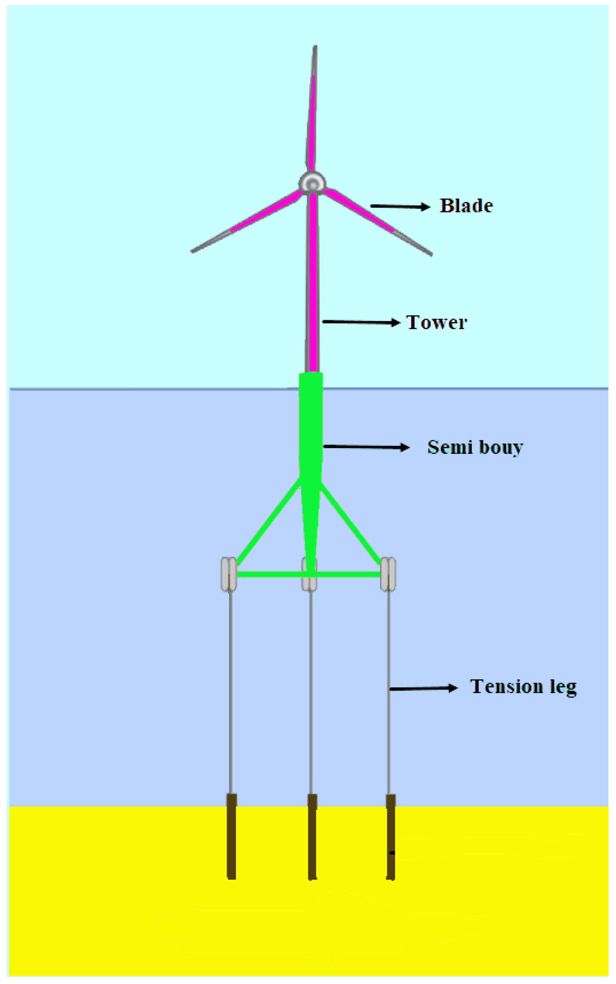
2. Modeling and Formulation of the TLP Systems

The general model of the tension leg platform (TLP) system is shown in Figure 1. The TLP systems used in this paper were based on the design proposed by Grad-Hassan [36]. Due to the collision of sea waves with TLP rigs, spring-like fluctuations were observed on the surface of the rigs. By modeling equations of motion (EOMs) of spring, the EOM could be written as follows:
[ M + A ] ζ ¨ + 0 t ι ( t τ ) . ζ ˙ d τ + D ζ ˙ + C ζ = X ( t ) + F T
In order to model the system considering floating hydrodynamic and aerodynamic models as well as calculations and equations presented in [36,37] regardless of high orders and nonlinear terms, the dynamic model and state-space equations of TLP systems could be obtained as follows:
X ˙ t = A X t + B U t + f e t Ψ t = C X t + D U
where the system’s state variables and inputs are defined as follows:
X t = [ χ r t χ p t χ v t χ 1 t χ 2 t χ 3 t χ 4 t ] T U t = [ Δ T G e n t ψ t ] T
The parameters are described in Table 1.

3. Type 2 Fuzzy Takagi-Sugeno

In order to consider uncertainties, the system dynamics are modeled using a type-2 Takagi-Sugeno fuzzy system. The Gaussian membership functions (MFs) are considered for inputs. The rules are written as:
Rule i: IF ω 1 ( χ ( t ) ) is M 1 i AND …AND ω p ( χ ( t ) ) is M p i THEN:
χ ˙ ( t ) = A i χ ( t ) + B i u ( t ) , y ( t ) = C i χ ( t )
where the number of rules is r, and the number of MFs is two for each input. The centers of MFs are considered to be the left and right bounds of the input range. In (4), ω ( χ ( t ) ) = { ω 1 ( χ ( t ) ) , . . . , ω a ( χ ( t ) ) } represents the premise of variables that are usually a function of state variables, M a i , i = 1 , 2 , , r indicates the fuzzy set, and u ( t ) , y ( t ) , A i and B i are system matrices. The i-th rule could be expressed as the following interval sets:
W i ( χ ( t ) ) = υ ̲ i ( χ ( t ) ) υ ¯ i ( χ ( t ) )
where υ ̲ i ( χ ( t ) ) and υ ¯ i ( χ ( t ) ) are the lower and upper firing strength in the i-th rule, respectively, which are expressed as follows:
υ ¯ i ( χ ( t ) ) = a = 1 p μ ¯ M a i ( ω a ( χ ( t ) ) υ ̲ i ( χ ( t ) ) = a = 1 p μ ̲ M a i ( ω a ( χ ( t ) )
where μ ̲ M a i ( ω a ( χ ( t ) ) 0 and μ ¯ M a i ( ω a ( χ ( t ) ) 0 are the lower and upper membership functions, respectively. Thus, it could be said for all of the rules that μ ¯ M a i ( ω a ( χ ( t ) ) μ ̲ M a i ( ω a ( χ ( t ) ) and υ ¯ i ( χ ( t ) ) υ ̲ i ( χ ( t ) ) . The IT2TS fuzzy system could be expressed as follows:
χ ˙ ( t ) = i = 1 r υ i ( χ ( t ) ) A i χ ( t ) + B i u ( t ) , y ( t ) = i = 1 r υ i ( χ ( t ) ) C i χ ( t ) ,
where:
υ ˜ i ( χ ( t ) ) = Υ ̲ ( χ ( t ) ) υ ̲ i ( χ ( t ) ) + Υ ¯ ( χ ( t ) ) υ ¯ i ( χ ( t ) ) υ i ( χ ( t ) ) = υ ˜ i ( χ ( t ) ) j = 1 r υ ˜ j ( χ ( t ) ) i = 1 r υ i ( χ ( t ) ) = 1
where Υ ¯ ( χ ( t ) ) and Υ ̲ ( χ ( t ) ) are nonlinear functions with the following characteristics:
0 Υ ̲ ( χ ( t ) ) 1 0 Υ ¯ ( χ ( t ) ) 1 Υ ̲ ( χ ( t ) ) + Υ ¯ ( χ ( t ) ) = 1

4. Learning Using a Square-Root Cubature Kalman Filter (SCKF)

The parameters of the second-order Takagi-Sugeno fuzzy system rules were tuned using the square-root cubature Kalman filter (SCKF) algorithm. The main advantage of SCKF over methods such as gradient descent, extended Kalman filter (EKF) and Lyapunov-based methods are that the nonlinear structure of FLS is preserved in the SCKF method. Moreover, other nonlinear methods such as unscented Kalman filter (UKF), EKF, and quadratic Kalman filter depend on the dimension of the problem. To use the Kalman filter (SCKF), the state-space model could be expressed as follows:
ϕ k + 1 = ϕ k + V k Υ k + 1 = Υ k + W k
where V k and W k are Gaussian noises associated with process and measurement, the covariances of which are Q k 1 and R k , respectively.
a.
The square root of the error covariance was considered as θ k 1 at k.
b.
Cubature points were calculated as follows (i = 1, 2, 3, …, m):
Z i , k 1 = θ k 1 ξ i + Z ^ k 1
where m = 2 N , ξ i = N and N are the number of free parameters and Z ^ k 1 denotes the parameters predicted by the second-order fuzzy system.
c.
Compute the propagated cubature points:
Υ i , k 1 = T 2 F L S ( ϕ i , k 1 )
d.
Estimate:
Υ ^ i , k k 1 = 1 m i = 1 m Υ i , k k 1
e.
The square root of the innovation covariance matrix was calculated as θ z , k 1 = T r i a ( [ λ k 1 θ R , k ] ) , where θ R , k represents the square root factor of R k , so that R k = θ R , k θ R , k T . The weighted centered matrix could be expressed as follows:
λ k 1 = 1 j Υ 1 , k 1 Υ ^ 1 , k 1 , Υ 2 , k 1 Υ ^ 2 , k 1 , Υ j , k 1 Υ j , k 1
f.
Compute the cross-variance matrix:
Φ x z , k 1 = κ k 1 λ k 1 T κ k 1 = 1 j Z 1 , k 1 Z ^ 1 , k 1 , Z 2 , k 1 Z ^ 2 , k 1 , , Z j , k 1 Z ^ j , k 1
g.
Estimate the Kalman gain:
W k = ( Φ x z , k 1 / Z z z , k 1 T ) / Z z z , k 1 T
h.
Compute the updated state:
ϕ ^ k = ϕ ^ k 1 + W k ( Υ k Υ ^ k 1 )
i.
Calculated covariance error:
Z z z , k 1 = T r i a ( [ κ k 1 W k λ k 1 W k Z R , k ] )
The state-space equations could be expressed as follows considering disturbances, time delays and a fuzzy model:
X . t = A X t + i = 1 n A d i + Δ A d i t X t τ i t + B U t + f e t Ψ t = C X t + D U t
where X t , A/ A d i , B , C, E and U t are n × 1 , n × n , n × m , m × n , n × m and m × 1 matrices, respectively. f e = E φ t is the disturbance and τ i t denotes the time-delay, so that the value of the time delay derivative is in the range of ζ k for all of the values of I = 1 , 2 , , n . According to τ ˙ k ( t ) ζ k < ζ , ζ is the upper bound for ζ k . Uncertainties of system 19 were considered as follows:
Δ A d i t D F l t H i
where D and H i denote fixed matrices and F l t is an unknown and time-varying matrix, so that the following inequality is always established:
F l T t F l t I , t

5. Stability Analysis
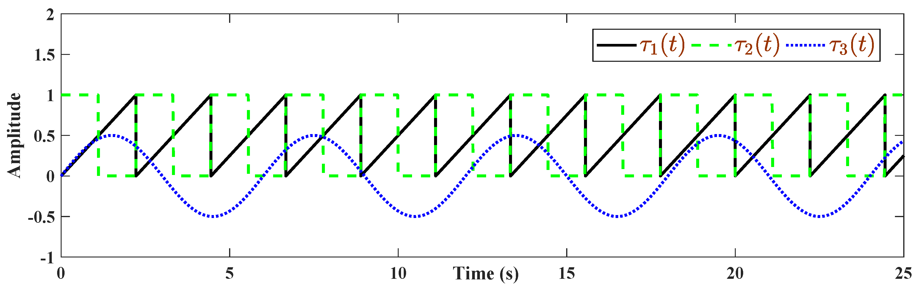
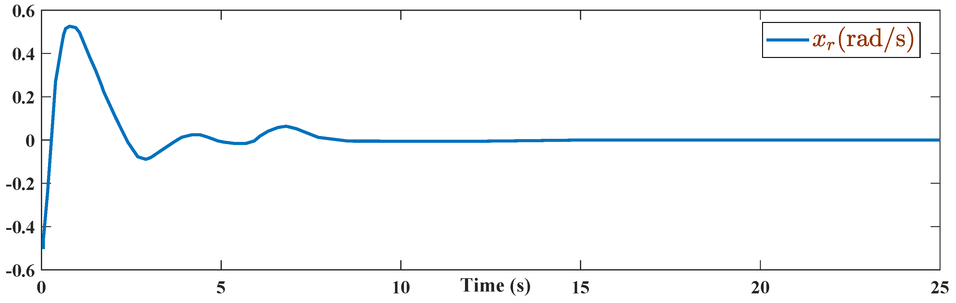
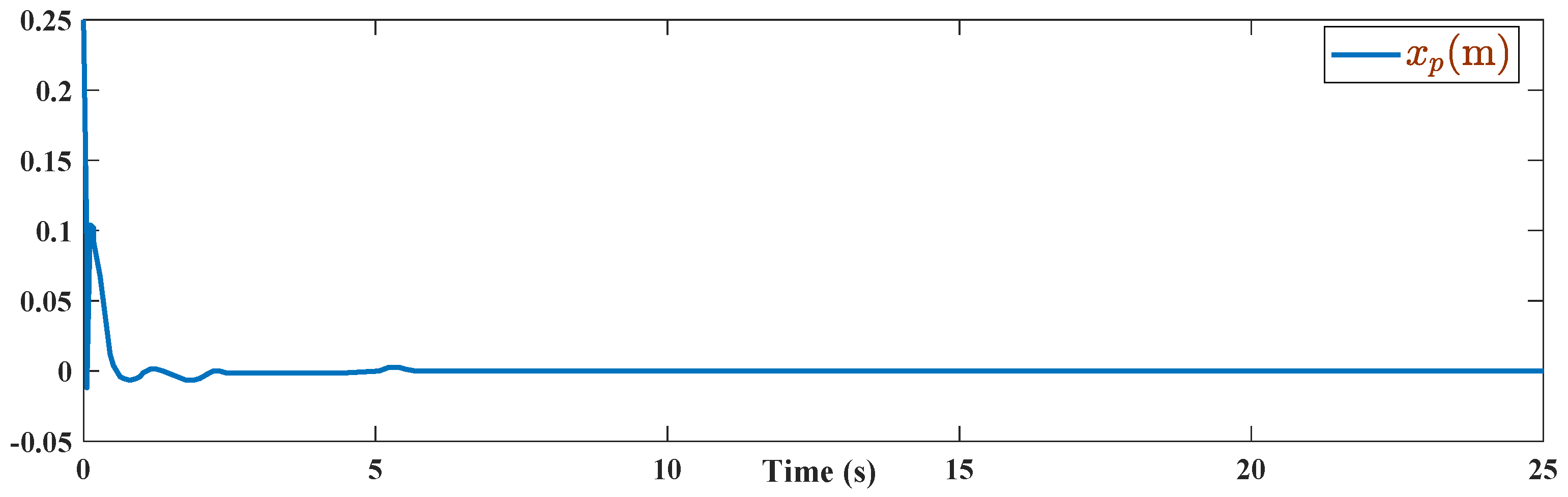
To prove TLP system stability, applying the following lemmas to systems with uncertainties and time delays makes it possible to achieve a robust controller.
Lemma 1.
For any x and z defined as matrices or vectors, the following inequality is always established [8]:
x T z + z T x α x T x + α 1 z T z
Lemma 2.
A set of nonlinear inequalities as Q ( χ ) Υ ( χ ) R 1 ( χ ) Υ T ( χ ) > 0 , R ( χ ) > 0 where R χ = R T χ and Υ χ = Υ T χ could be converted into LMI as follows [38]:
[ Q ( χ ) Υ ( χ ) Υ ( χ ) T R ( χ ) ] > 0
To eliminate the disturbance effects, consider 0 < f e t 2 sup < Ψ t 2 f e t 2 γ 1 , where γ represents a constant. Then:
Ψ T t Ψ t γ 2 E T E φ T t φ t Ψ T t Ψ t γ γ 1 E T E φ T t φ t < 0
Then, the positive definite function of V χ t is defined as a Lyapunov candidate as follows:
V χ t = X T t Q X t + i = 1 n t τ i t t X T τ i t R i X τ i t d τ i
where Q = Q T 0 and R i = R i T 0 are determined. After obtaining the derivative of V χ t , this results in:
V ˙ χ t + Ψ T t Ψ t γ γ 1 E T E φ T t φ t < 0 V ˙ χ t + X T t C T C X t γ γ 1 E T E φ T t φ t < 0
Since the second term of (1) is negative, we should investigate the conditions under which the derivative of function V χ t becomes negative, so that (26) becomes less than zero. For this purpose, the derivative of (25) was calculated, assuming that the time-delay derivative is always in the range of ζ k
V ˙ χ t = X ˙ T t Q X t + X T t Q X ˙ t + i = 1 n X T t R i X t i = 1 n 1 ζ i X T t τ i t R i X t τ i t
By substituting the value of X ˙ t into the above equation and considering U t = K X t , we have:
V ˙ χ t = X T t A + B ι T Q X t + i = 1 n X T t τ i t A d i + Δ A d i t T Q X t
+ φ T t E T Q x t + X T t Q A + B ι X t + X T t Q i = 1 n A d i + Δ A d i t X t τ i t +
X T t Q E φ t + i = 1 n X T t R i X t i = 1 n ( 1 ζ i ) X T t τ i t R i X t τ i t
Considering (20) and (28), we obtain:
V ˙ χ t = X T t Q A + B ι + A + B ι T Q X t + X T t Q D F l E 1 + E 1 T F l T D T Q X t + X T t Q D F l E 2 ι + ι E 2 T F l T D T Q X t +
X T t Q i = 1 n A d i X t τ i t + X T t Q i = 1 n D F l H i X t τ i t + i = 1 n X T t τ i t A d i T Q X t + i = 1 n X T t τ i t H i T F l T D T Q X t
+ φ T t E T Q X t + X T t Q E φ t + i = 1 n X T t R i X t i = 1 n ( 1 ζ i ) X T t τ i t R i X t τ i t
According to Lemma 2, the following inequalities could be obtained:
X T t Q D F l E 1 + E 1 T F l T D T Q X t α 1 X T t Q D D T Q X t + α 1 1 X T t E 1 T E 1 X t
X T t Q D F l E 2 ι + ι E 2 T F l T D T Q X t α 2 X T t Q D D T Q X t + α 2 1 X T t ι T E 2 T E 2 K X t
X T t Q i = 1 n D F l H i X t τ i t + i = 1 n X T t τ i t H i T F l T D T Q X t i = 1 n β i X T t Q D D T Q X t + i = 1 n β i 1 χ T t τ i t H i T H i X t τ i t
Based on (30)–(32) and placing them in (29), we have:
X T t Q A + B ι + A + B ι T Q X t + α 1 X T t Q D D T Q X t + α 2 X T t Q D D T Q X t + i = 1 n β i χ T t Q D D T Q X t +
i = 1 n β i 1 χ T t τ i t H i T H i X t τ i t + X T t Q i = 1 n A d i X t τ i t + i = 1 n X T t τ i t A d i T Q X t + φ T t E T Q X t
By substituting (33) into (26), the following result is obtained:
X T t Q A + B ι + A + B ι T Q X t + α 1 X T t Q D D T Q X t + α 2 X T t Q D D T Q X t + i = 1 n β i χ T t Q D D T Q X t +
i = 1 n β i 1 χ T t τ i t H i T H i X t τ i t + X T t Q i = 1 n A d i X t τ i t + i = 1 n X T t τ i t A d i T Q X t + φ T t E T Q X t +
X T t Q E φ t + i = 1 n X T t R i X t i = 1 n ( 1 ζ i ) X T t τ i t R i X t τ i t + X T t C T C X t γ γ 1 E T E φ T t φ t < 0
Inequality (34) could be rewritten as follows:
X t X t τ 1 t X t τ i t φ t T Ω ¯ 0 + C 0 0 0 T γ C 0 0 0 · X t X t τ 1 t X t τ i t φ t < 0
Δ = Ω ¯ 0 + C 0 0 0 T γ C 0 0 0 < 0
where:
Ω ¯ 0 = Γ 00 Γ 01 Γ 0 i Γ 0 i + 1 * Γ 11 0 0 0 * 0 0 * * * Γ i i 0 * * * * Γ i + 1 i + 1
where i = 1,2,...,n and * indicate the elements of matrix 35 that are transmitted symmetrically relative to the main diagonal.
Γ 00 = Q A + B ι + A + B ι T Q + α 1 + α 2 + i = 1 n β i Q D D T Q + i = 1 n R i Γ 01 = Q A d 1 Γ 0 i = Q A d i Γ 0 i + 1 =
Q E Γ 11 = β 1 1 H 1 T H 1 1 ζ 1 R 1 Γ i i = β i 1 H i T H i 1 ζ i R i Γ i + 1 i + 1 = E T E γ 1 I
Defining Δ as (36) and considering (38), one has:
Δ = Q A + B ι + A + B ι T Q + α 1 + α 2 + i = 1 n β i Q D D T Q + i = 1 n R i * * *
Q A d i Q A d i Q E β 1 1 H 1 T H 1 1 ζ 1 R 1 0 0 0 0 0 * * β i 1 H i T H i 1 ζ i R i 0 * * * E T E γ 1 I + C 0 0 0 T γ C 0 0 0 < 0
Using Lemma 1, inequality (39) becomes:
Δ = Q A + B ι + A + B ι T Q + α 1 + α 2 + i = 1 n β i Q D D T Q + i = 1 n R i * * * *
Q A d i Q A d i β 1 1 H 1 T H 1 1 ζ 1 R 1 0 0 0 * * β i 1 H i T H i 1 ζ i R i * * * * * * Q E C T 0 0 0 0 0 0 E T E γ 1 I 0 * γ 1 I < 0
By achieving the above equation, the derivative of the Lyapunov function becomes negative and system stability is ensured.
Remark 1.
In this paper, an LMI-bases approach is developed for robustness analysis of the designed type-2 FLC. The readers can find other methods for robustness analysis of Type-2 FLCs in [11,39,40].

6. Simulation

As shown in the previous section, TLP systems are unstable under three modes: disturbances, multiple time-varying delays, and uncertainties. As described in this section, after calculating the required parameters, a simulation was performed in MATLAB-Simulink. LMIs were used to obtain the control gain. In the previous section, the matrix inequality of (40) was obtained while proving the system stability. The resulting inequality was not affine. An affine expression could be achieved by multiplying both sides of the inequality by d i a g P , I , I , I , , I , I , I . In this case, optimal values of P, L, α 1 , α 2 , β 1 ¯ , β 2 ¯ , β 3 ¯ , γ ¯ , R 1 ¯ , R 2 ¯ and R 3 ¯ were computed considering three time-varying delays (n = 3) and wind speeds of 16 and 24 m/s, so that P = Q 1 , L = K P , β i 1 = β ¯ i , γ 1 = γ ¯ and R i 1 = R ¯ i . According to the mentioned conditions, (40) and (20) were converted into the following forms:
X . t = A + Δ A t X t + i = 1 3 A d i + Δ A d i t X t τ i t + B + Δ B t U t + E φ t
Δ = A P + B L + P A T + L T B T + α 1 + α 2 + β 1 + β 2 + β 3 A d 1 A d 2 * β ¯ 1 H 1 T H 1 1 ζ 1 R 1 0 * * β ¯ 2 H 2 T H 2 1 ζ 2 R 2 * * * * * * * * * * * * * * * * * * * * * * * *
A d 3 E P C T P E 2 L P P P 0 0 0 0 0 0 0 0 0 0 0 0 0 0 0 0 β ¯ 3 H 3 T H 3 1 ζ 3 R 3 0 0 0 0 0 0 0 * E T E γ ¯ I 0 0 0 0 0 0 * * γ ¯ I 0 0 0 0 0 * * * α 1 E 1 T E 1 1 0 0 0 0 * * * * α 2 I 0 0 0 * * * * * R ¯ 1 0 0 * * * * * * R ¯ 2 0 * * * * * * * R ¯ 3 < 0
A d 1 = 0.8 0.2 0.05 0 0.07 0 0 0.17 0.01 0 0 0.01 0 0 0.15 0.1 0.2 0.06 0.07 0.021 0.1 0.02 0 0 0 0.2 0.3 0.05 0.01 0.01 0.1 0.1 0 0.01 0 0 0.1 0.01 0.1 0 0.1 0 0.12 0 0.01 0.02 0.1 0 0.1
A d 2 = 0.6 0.15 0.05 0 0 0.1 0.5 0 0 0.01 0.21 0.1 0 0 0.25 0.06 0.5 0.06 0.07 0.121 0.1 0.15 0 0 0.01 0.3 0.05 0.25 0.01 0.01 0.2 0.1 0 0.01 0.01 0.3 0.12 0 0.1 0 0.1 0 0.2 0 0.3 0.12 1 0.21 0.1
A d 3 = 0.8 0.015 0.15 0 0 0.1 0.05 0 0 0.1 0.1 0.1 0 0 0.015 0.06 0.05 0.06 0.07 0.21 0.01 0.15 0.1 0 0.1 0.03 0.05 0.025 0.01 0.1 0.02 0.1 0.2 0.01 0.01 0.03 0.1 0 0.2 0 0.1 0 0.02 0 0.3 0.12 1 0.1 0.1
D = I , ζ 1 = ζ = 2 = ζ 3 = 0.5 , E 1 = 0.2 I , E 2 = 0.3 I , H 1 = 0.4 I , H 2 = 0.5 I
H 3 = 1 0 0.5 0.25 0.23 0.05 0.2 0 1 1 0.02 0.1 0.6 0.32 T
F 1 t = sin t / 2 , F 2 t = cos 2 t / 2 , F 3 t = sin 3 t + cos t / 2 F 4 t = sin 2 t + cos t / 2 , F 5 t = cos 2 t / 2
The necessary gain for the fuzzy TS controller was achieved by obtaining the optimal value of ι 1 .
ι 1 = 3.4659 3.0050 0.1515 1.1428 0.3853 1.3840 2.9467 10.3529 8.9760 0 . 4524 3.4136 1.1509 4.1339 8.8019 ι 2 = 15.7412 12.6518 0.7701 5.1992 1.5073 6.0574 17.0996 48.0559 36.6244 2.3511 15.8726 4.6017 18.4923 52.2028
In the first scenario, the initial conditions of the system were considered as:
χ 0 = 0.5 0.25 0.01 0.5 0.2 0.75 0.3 T
and the applied disturbance was set to φ ( t ) = 100 sin ( π t ) . From Figure 2, time-delays were considered as τ 1 ( t ) = 0.5 sin π 3 t with a sawtooth wave.
The Figure 3, Figure 4, Figure 5, Figure 6, Figure 7, Figure 8 and Figure 9 illustrate the behavior of the system’s state variables and how they converged to zero with minimal fluctuations.
In the second scenario, the initial conditions were considered as χ 0 = [ 0.9 0.2 0.1 0.05 0.6 0.7 0.8 ] T and the applied disturbance was set to φ ( t ) = 100 + 60 cos ( 3 π t ) + χ 4 × 80 sin ( 2 π t ) . From Figure 10, time-delays are a pulse wave at the amplitude of first state as well as a sawtooth wave of τ 3 ( t ) = cos π t at the amplitude of first state.
After applying the above values, the system was simulated using Simulink-MATLAB. The obtained results are depicted in Figure 11, Figure 12, Figure 13, Figure 14, Figure 15, Figure 16 and Figure 17.
This study aimed to stabilize and minimize oscillations caused by the collision of sea waves with TLPs. Therefore, the necessary conditions were provided for designing a fuzzy controller using the linear matrix inequality technique. Results of implementing the system in the two scenarios revealed that all of the system state variables converged to zero within a short period of time.
To better examine the accuracy of the designed approach, a comparison analysis was carried out with some related methods, such as a type-1 fuzzy controller (T1FLC) [10] and integral load control (ILC) [41]. The RMSEs are given in Table 2. The values of RMSEs depicted in Table 2 verify that the designed type-2 fuzzy approach has better accuracy in the presence of natural perturbations of TLP systems.

7. Conclusions

This paper proposed a novel control method based on second-order Sugeno fuzzy systems to stabilize offshore floating WTs subject to oscillating motions resulting from sea turbulences and waves. The parameters of fuzzy control system rules were tuned using a square-root cubature Kalman filter. The effectiveness and performance of the proposed approach was assessed using a simulation study of a tension leg platform. Two scenarios were considered in the performance analysis. In the first scenario, in addition to dynamic uncertainties, a sinusoidal disturbance was applied to the system as a dynamic perturbation. In the second scenario, in addition to uncertainties and disturbances, a time-varying delay was also added as a time-varying pulse. The obtained results showed that the system is well stabilized and the oscillations are well minimized. Additionally, the system’s state variables converged to zero within a short period of time. This study focused on the design of an optimized fuzzy controller to tackle the perturbations such as turbulence and sea waves and uncertainties of TLP. Our future work will look into expanding the approach to mitigate the effect of system faults.

Author Contributions

Conceptualization, B.F. and M.B.; Formal analysis, B.F. and A.K.A.; Funding acquisition, M.B.; Investigation, B.F., K.A.A., M.B. and A.M.; Methodology, B.F., K.A.A., M.B., A.K.A., A.M., S.M. and A.F.; Resources, K.A.A., M.B., A.K.A., A.M., S.M. and A.F.; Supervision, A.M. and S.M.; Writing—original draft, B.F.; Writing—review and editing, K.A.A., M.B., A.K.A., A.M., S.M. and A.F. All authors have read and agreed to the published version of the manuscript.

Funding

Funding: This work was supported by the Taif University Researchers Supporting Project grant number (TURSP-2020/266), of Taif University, Taif, Saudi Arabia.

Institutional Review Board Statement

Not applicable.

Informed Consent Statement

Not applicable.

Data Availability Statement

The study do not report any data.

Acknowledgments

The authors extend their appreciation to the Deanship of Scientific Research—Majmaah University for supporting this work under project number (R-2022-63).

Conflicts of Interest

The authors declare no conflict of interest.

References

  1. Global Wind Report. 2021. Available online: https://gwec.net/global-wind-report-2021/ (accessed on 1 February 2022).
  2. Delgado, I.; Fahim, M. Wind Turbine Data Analysis and LSTM-Based Prediction in SCADA System. Energies 2021, 14, 125. [Google Scholar] [CrossRef]
  3. Fahim, M.; Fraz, K.; Sillitti, A. TSI: Time series to imaging based model for detecting anomalous energy consumption in smart buildings. Inf. Sci. 2020, 523, 1–13. [Google Scholar] [CrossRef]
  4. Corley, B.; Koukoura, S.; Carroll, J.; McDonald, A. Combination of thermal modelling and machine learning approaches for fault detection in wind turbine gearboxes. Energies 2021, 14, 1375. [Google Scholar] [CrossRef]
  5. Corley, B.; Carroll, J.; McDonald, A. Thermal modelling of a small wind turbine gearbox for condition monitoring. J. Eng. 2019, 2019, 5335–5339. [Google Scholar] [CrossRef]
  6. Gajewski, P.; Pieńkowski, K. Control of the Hybrid Renewable Energy System with Wind Turbine, Photovoltaic Panels and Battery Energy Storage. Energies 2021, 14, 1595. [Google Scholar] [CrossRef]
  7. Gajewski, P.; Pieńkowski, K. Advanced control of direct-driven PMSG generator in wind turbine system. Arch. Electr. Eng. 2016, 65, 643–656. [Google Scholar] [CrossRef]
  8. Chen, C.Y.; Lin, J.W.; Lee, W.I.; Chen, C.W. Fuzzy control for an oceanic structure: A case study in time-delay TLP system. J. Vib. Control. 2010, 16, 147–160. [Google Scholar] [CrossRef]
  9. Chen, C.W. Modeling, control, and stability analysis for time-delay TLP systems using the fuzzy Lyapunov method. Neural Comput. Appl. 2011, 20, 527–534. [Google Scholar] [CrossRef]
  10. Kiamini, S.; Jalilvand, A.; Mobayen, S. LMI-based robust control of floating tension-leg platforms with uncertainties and time-delays in offshore wind turbines via TS fuzzy approach. Ocean Eng. 2018, 154, 367–374. [Google Scholar] [CrossRef]
  11. Derugo, P.; Szabat, K.; Pajchrowski, T.; Zawirski, K. Fuzzy Adaptive Type II Controller for Two-Mass System. Energies 2022, 15, 419. [Google Scholar] [CrossRef]
  12. Pekaslan, D.; Wagner, C.; Garibaldi, J.M. ADONiS-Adaptive Online Nonsingleton Fuzzy Logic Systems. IEEE Trans. Fuzzy Syst. 2019, 28, 2302–2312. [Google Scholar] [CrossRef]
  13. Tang, Y.; Pedrycz, W. Oscillation-bound estimation of perturbations under Bandler-Kohout subproduct. IEEE Trans. Cybern. 2021. [Google Scholar] [CrossRef] [PubMed]
  14. Mohammadzadeh, A.; Ghaemi, S. A modified sliding mode approach for synchronization of fractional-order chaotic/hyperchaotic systems by using new self-structuring hierarchical type-2 fuzzy neural network. Neurocomputing 2016, 191, 200–213. [Google Scholar] [CrossRef]
  15. Yorgancıoğlu, F.; Kömürcügil, H. Single-input fuzzy-like moving sliding surface approach to the sliding mode control. Electr. Eng. 2008, 90, 199–207. [Google Scholar] [CrossRef]
  16. Li, Y.; Lin, J.; Niu, G.; Wu, M.; Wei, X. A Hilbert–Huang Transform-Based Adaptive Fault Detection and Classification Method for Microgrids. Energies 2021, 14, 5040. [Google Scholar] [CrossRef]
  17. Michalski, M.A.; Melani, A.H.; da Silva, R.F.; de Souza, G.F.; Hamaji, F.H. Fault Detection and Diagnosis Based on Unsupervised Machine Learning Methods: A Kaplan Turbine Case Study. Energies 2022, 15, 80. [Google Scholar] [CrossRef]
  18. Chen, C.S.; Hu, N.T. Model Reference Adaptive Control and Fuzzy Neural Network Synchronous Motion Compensator for Gantry Robots. Energies 2022, 15, 123. [Google Scholar] [CrossRef]
  19. Albu, A.; Precup, R.E.; Teban, T.A. Results and challenges of artificial neural networks used for decision-making and control in medical applications. Facta Univ. Ser. Mech. Eng. 2019, 17, 285–308. [Google Scholar] [CrossRef]
  20. Mai, D.S.; Dang, T.H.; Ngo, L.T. Optimization of interval type-2 fuzzy system using the PSO technique for predictive problems. J. Inf. Telecommun. 2021, 5, 197–213. [Google Scholar] [CrossRef]
  21. Badri Narayanan, K.; Sreekumar, M. Diagnosing of Risk State in Subsystems of CNC Turning Center using Interval Type-2 Fuzzy Logic System with Semi Elliptic Membership Functions. Int. J. Fuzzy Syst. 2021, 53, 1–18. [Google Scholar] [CrossRef]
  22. Takahashi, A.; Takahashi, S. A new interval type-2 fuzzy logic system under dynamic environment: Application to financial investment. Eng. Appl. Artif. Intell. 2021, 100, 104154. [Google Scholar] [CrossRef]
  23. Mohammadzadeh, A.; Sabzalian, M.H.; Ahmadian, A.; Nabipour, N. A dynamic general type-2 fuzzy system with optimized secondary membership for online frequency regulation. ISA Trans. 2021, 112, 150–160. [Google Scholar] [CrossRef] [PubMed]
  24. Martínez, G.E.; Gonzalez, C.I.; Mendoza, O.; Melin, P. General type-2 fuzzy sugeno integral for edge detection. J. Imaging 2019, 5, 71. [Google Scholar] [CrossRef] [Green Version]
  25. Ontiveros-Robles, E.; Melin, P. Toward a development of general type-2 fuzzy classifiers applied in diagnosis problems through embedded type-1 fuzzy classifiers. Soft Comput. 2020, 24, 83–99. [Google Scholar] [CrossRef]
  26. Cao, Y.; Raise, A.; Mohammadzadeh, A.; Rathinasamy, S.; Band, S.S.; Mosavi, A. Deep learned recurrent type-3 fuzzy system: Application for renewable energy modeling/prediction. Energy Rep. 2021, 7, 8115–8127. [Google Scholar] [CrossRef]
  27. Shukla, A.K.; Muhuri, P.K. General type-2 fuzzy decision making and its application to travel time selection. J. Intell. Fuzzy Syst. 2019, 36, 5227–5244. [Google Scholar] [CrossRef]
  28. Nabipour, N.; Qasem, S.N.; Jermsittiparsert, K. Type-3 fuzzy voltage management in PV/hydrogen fuel cell/battery hybrid systems. Int. J. Hydrogen Energy 2020, 45, 32478–32492. [Google Scholar] [CrossRef]
  29. Liu, Z.; Mohammadzadeh, A.; Turabieh, H.; Mafarja, M.; Band, S.S.; Mosavi, A. A New Online Learned Interval Type-3 Fuzzy Control System for Solar Energy Management Systems. IEEE Access 2021, 9, 10498–10508. [Google Scholar] [CrossRef]
  30. Ma, C.; Mohammadzadeh, A.; Turabieh, H.; Mafarja, M.; Band, S.S.; Mosavi, A. Optimal Type-3 Fuzzy System for Solving Singular Multi-Pantograph Equations. IEEE Access 2020, 8, 225692–225702. [Google Scholar] [CrossRef]
  31. Alattas, K.A.; Mohammadzadeh, A.; Mobayen, S.; Aly, A.A.; Felemban, B.F. A New Data-Driven Control System for MEMSs Gyroscopes: Dynamics Estimation by Type-3 Fuzzy Systems. Micromachines 2021, 12, 1390. [Google Scholar] [CrossRef]
  32. Wang, J.h.; Tavoosi, J.; Mohammadzadeh, A.; Mobayen, S.; Asad, J.H.; Assawinchaichote, W.; Skruch, P. Non-Singleton Type-3 Fuzzy Approach for Flowmeter Fault Detection: Experimental Study in a Gas Industry. Sensors 2021, 21, 7419. [Google Scholar] [CrossRef] [PubMed]
  33. Tian, M.W.; Yan, S.R.; Mohammadzadeh, A.; Tavoosi, J.; Mobayen, S.; Safdar, R.; Assawinchaichote, W.; Zhilenkov, A. Stability of Interval Type-3 Fuzzy Controllers for Autonomous Vehicles. Mathematics 2021, 9, 2742. [Google Scholar] [CrossRef]
  34. Chen, C.W. Stability conditions of fuzzy systems and its application to structural and mechanical systems. Adv. Eng. Softw. 2006, 37, 624–629. [Google Scholar] [CrossRef]
  35. Tsai, P.W.; Alsaedi, A.; Hayat, T.; Chen, C.W. A novel control algorithm for interaction between surface waves and a permeable floating structure. China Ocean Eng. 2016, 30, 161–176. [Google Scholar] [CrossRef]
  36. Karimirad, M. Stochastic Dynamic Response Analysis of Spar-Type wind Turbines with Catenary or Taut Mooring Systems. 2011. Available online: http://hdl.handle.net/11250/237877 (accessed on 1 February 2022).
  37. Nazir, R. Taylor series expansion based repetitive controllers for power converters, subject to fractional delays. Control Eng. Pract. 2017, 64, 140–147. [Google Scholar] [CrossRef]
  38. Song, R.; Zhu, Q. Stability of linear stochastic delay differential equations with infinite Markovian switchings. Int. J. Robust Nonlinear Control 2018, 28, 825–837. [Google Scholar] [CrossRef]
  39. Hosseinzadeh, M.; Sadati, N.; Zamani, I. H disturbance attenuation of fuzzy large-scale systems. In Proceedings of the 2011 IEEE International Conference on Fuzzy Systems (FUZZ-IEEE 2011), Taipei, Taiwan, 27–30 June 2011; pp. 2364–2368. [Google Scholar]
  40. Linda, O.; Manic, M. Uncertainty-robust design of interval type-2 fuzzy logic controller for delta parallel robot. IEEE Trans. Ind. Inform. 2011, 7, 661–670. [Google Scholar] [CrossRef]
  41. Zhang, M.; Li, X.; Tong, J.; Xu, J. Load control of floating wind turbine on a Tension-Leg-Platform subject to extreme wind condition. Renew. Energy 2020, 151, 993–1007. [Google Scholar] [CrossRef]
Figure 1. Schematic representation of tension leg platform.
Energies 15 01705 g001
Figure 2. System delays related to Scenario 1.
Energies 15 01705 g002
Figure 3. Time response of x r related to Scenario 1.
Energies 15 01705 g003
Figure 4. Time response of x p related to Scenario 1.
Energies 15 01705 g004
Figure 5. Time response of x v related to Scenario 1.
Energies 15 01705 g005
Figure 6. Time response of x 1 related to Scenario 1.
Energies 15 01705 g006
Figure 7. Time response of x 2 related to Scenario 1.
Energies 15 01705 g007
Figure 8. Time response of x 3 related to Scenario 1.
Energies 15 01705 g008
Figure 9. Time response of x 4 related to Scenario 1.
Energies 15 01705 g009
Figure 10. System delays related to Scenario 2.
Energies 15 01705 g010
Figure 11. Time response of x r related to Scenario 2.
Energies 15 01705 g011
Figure 12. Time response of x p related to Scenario 2.
Energies 15 01705 g012
Figure 13. Time response of x v related to Scenario 2.
Energies 15 01705 g013
Figure 14. Time response of x 1 related to Scenario 2.
Energies 15 01705 g014
Figure 15. Time response of x 2 related to Scenario 2.
Energies 15 01705 g015
Figure 16. Time response of x 3 related to Scenario 2.
Energies 15 01705 g016
Figure 17. Time response of x 4 related to Scenario 2.
Energies 15 01705 g017
Table 1. Parameter description.
ParameterDescription
MSystem mass (mast + turbine)
A Mass added to the system by wave effect for infinite frequencies
K ( t ) The forgetting function is related to the effects of hydrodynamic memory
CSystem energy saving coefficient
DLinear adjustment coefficient of the system
ζ ( t ) Spatial displacement
F ( t ) Time-dependent wave excitation forces
F T t Time-dependent aerodynamic force
x r ( t ) , r a d / s Average rotor rotation speed
x p ( t ) Deviation from the average wave location
x v ( t ) , m / s Wave speed
x 1 ( t ) , x 2 ( t ) , x 3 ( t ) , x 4 ( t ) N m s Effects of system memory
f e ( t ) Disorder entered on the system
Table 2. Performance comparison.
Proposed MethodT1FLC [10]ILC [41]
χ 1 1.77662.01252.7180
χ 2 0.60561.42411.8914
χ 3 0.11530.51010.9421
χ 4 0.11460.12470.8401
Publisher’s Note: MDPI stays neutral with regard to jurisdictional claims in published maps and institutional affiliations.

