


Abstract
Due to the introduction of frequency offsets, the pattern synthesis problem of sparse Frequency diverse array (FDA) becomes more complicated than that of the phased array. A typical way to solve this problem is to use a global optimization algorithm, but this is usually time-consuming. In this paper, we propose an efficient non-iterative beampattern synthesis approach for sparse FDA. For a given reference pattern, which can be generated by other synthesis methods, we first sample it uniformly and construct the Hankel matrix with the sampled data. By low-rank processing, a low-rank approximation version of the Hankel matrix can then be obtained. Finally, the matrix enhancement and matrix pencil (MEMP) and matrix pencil (MP) methods are applied to estimate the antenna positions, frequency offsets, and excitations of the obtained array from the approximated matrix. Besides this, two typical FDA frameworks including multi-carrier FDA (MCFDA) and standard FDA (SFDA) are considered. Numerical simulation results prove that the proposed method outperforms the existing methods in terms of synthesis error, average runtime, and percentage of saving elements.
1. Introduction
Frequency diverse array (FDA), as a new type of flexible scanning array, was proposed by Antonik in 2006 [1,2]. By introducing a tiny frequency offset between adjacent antenna elements, the FDA generates a range-angle-dependent steering vector. Benefiting from this feature, the FDA can provide directional gain or attenuation in range-angle space, thereby delivering potential applications in target range-angle estimation and mainlobe interference suppression [3,4,5]. Compared with phased array (PA), the FDA offers an additional design variable, i.e., frequency offset; thus, designers can obtain the desired beampattern by optimizing the frequency offset. In the past decade, numerous investigations have been developed to design frequency offset for yielding a required beampattern [6,7,8,9,10,11]. Additionally, Gao et al. proposed a multi-carrier FDA scheme, which can bring more freedom for performance improvement [12].
As a matter of fact, most of the methods mentioned above are designed in a uniform FDA framework. Despite the success of these techniques, the synthesis of uniformly spaced FDA sometimes requires a large number of elements to produce the desired pattern characteristics. However, in some cases where the weight and size of antenna systems are limited, it is very significant to obtain the desired beampattern performance with the sparse array. In the past several decades, the pattern synthesis problem of the sparse array has been extensively studied [13,14,15,16,17,18,19,20,21,22]. The typical synthesis methods of sparse arrays can be summarized into three categories: (1) global optimization algorithms [13,14,15,16]; (2) non-iterative algorithms [17,18,19]; and (3) sparsity constraint-based algorithms [20,21,22]. Nevertheless, most of these methods are designed for PAs, and the research on beampattern synthesis for sparse FDA is still lacking. Unlike the pattern synthesis for PAs, the FDA pattern synthesis should consider a new design variable, namely, frequency offset, which makes the sparse FDA synthesis more complicated.
To address this issue, Yang et al. proposed a sparse FDA design method, using the artificial bee colony (ABC) algorithm to jointly optimize the number, position, and frequency offset of antenna elements [23]. Using the convex optimization technique, a group sparse multicarrier FDA thinning method was presented in [24]. This method reduced the number of elements by turning off the antennas with very small and irrelevant weights. Chen et al. reformulated the sparse FDA synthesis problem as finding a joint sparse weight vector and placed the antenna unit corresponding to the non-zero mapping position of the joint sparse weight vector [25]. Although these works can obtain the desired pattern, they either need to be searched in high-dimensional parameter space or a time-consuming iterative process, which will bring a considerable computational burden, especially for large arrays. As far as we know, no non-iterative sparse FDA synthesis algorithm has been proposed so far.
Inspired by this observation, this paper proposes an efficient non-iterative sparse FDA beampattern synthesis method. The two typical FDA structures are considered respectively, namely, standard FDA (SFDA) and multi-carrier FDA (MCFDA). For the SFDA, we sample the desired pattern uniformly, build the block Hankel matrix with the sampled data, and perform low-rank approximate on the block Hankel matrix. The matrix enhancement matrix pencil (MEMP) method can then be applied to estimate array positions, frequency offsets, and excitations from the approximated matrix. For MCFDA, the array factor can be expressed as the product of the main cut plane of the pattern in the range and angle dimensions, and therefore we only need to consider two simple one-dimensional parameter estimation problems, which can be easily solved by matrix pencil (MP) method. Compared with the reported sparse FDA beampattern synthesis methods presented in [23,24,25], the advantages of the proposed algorithm can be summarized as (i) it is a non-iterative method and therefore computationally efficient, and (ii) the proposed method is more flexible in assigning element positions and frequency offsets, which are not restricted by the regular lattice. Numerical examples show that the proposed algorithm can accurately approximate the desired beampattern with a sparse FDA in a short time.
The structure of this paper is organized as follows. Section 2 gives the array factor model of SFDA and MCFDA. In Section 3, the proposed pattern synthesis methods for sparse SFDA and MCFDA are derived respectively. Numerical examples are performed to prove the effectiveness of the proposed algorithm in Section 4. Section 5 concludes this paper.
2. Array Factor of FDA
In this section, two typical FDA structures will be considered, namely, SFDA and MCFDA. Subsequently, the two FDA array factors were fully investigated.
2.1. Standard FDA
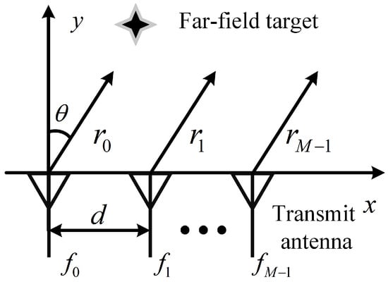
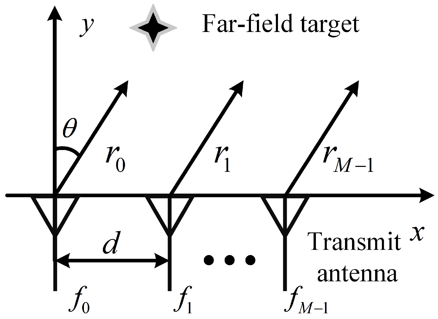
In the standard FDA, a set of frequency offsets is introduced across the array, resulting in a range-angle dependent steering vector. Consider a uniform SFDA consisting of M antennas with adjacent spacing d, as shown in Figure 1. Let the first element be the reference array element, and the transmitted frequency of the mth antenna element can be expressed as
where is the carrier frequency of the FDA system, and is the frequency offset of mth element. Then, the radiated signal by the mth antenna can be written as
Figure 1.
The schematic diagram of standard frequency diverse array.
Suppose there is a target located at in the observation region, under far-field conditions, and the transmitted signal collected at the target can be modeled as
where is the slope range between the target and the mth element, and it can be approximated as under far-field condition. and c represent the complex transmit weight of the mth element and the speed of light. Substituting Equation (2) into Equation (3), the array factor of SFDA can be formulated as
In general, the condition is satisfied in the FDA radar system; thus, the term can be ignored. Noteworthy, the time effect can be eliminated by using multi-channel mixing receiver [10], and, hence, the time-dependent term in Equation (4) can also be eliminated. Ignore the constant term , and then Equation (4) can be rewritten as
2.2. Multi-Carrier FDA
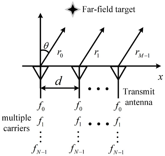
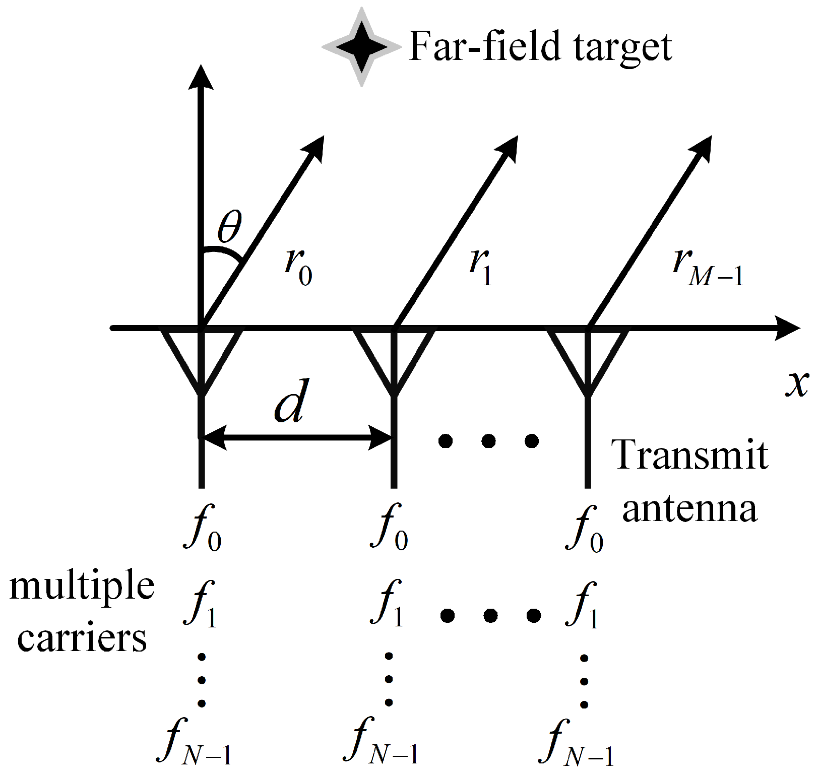
In MCFDA, each array element radiates multiple carrier signals [12], thus increasing the freedom of the array. The MCFDA composed of a M antenna with adjacent spacing d is considered, as shown in Figure 2. Multiple carriers are composed of N frequency components, and the transmitted frequency of the nth carrier can be expressed as
Figure 2.
The schematic diagram of multi-carrier frequency diverse array.
For a target in the far-field, the corresponding array factor for MCFDA can be expressed as
where is the transmit weight of the nth carrier of the mth element. Substitute Equation (6) and into Equation (7) to yield
Considering the common factor can be ignored, and the time-dependent term also can be canceled with the multi-channel mixing receiver. Accordingly, the final array factor of MCFDA can be expressed as
3. Proposed Synthesis Method for Sparse FDA
Due to the introduction of frequency offsets, the pattern synthesis problem of the FDA becomes more complicated than traditional array pattern synthesis. In the currently reported works, global optimization or convex optimization techniques have been introduced to deal with this problem [23,24,25]. However, these methods require a time-consuming search or iterative process. To alleviate this problem, an efficient non-iterative sparse FDA beampattern synthesis method is presented in this section.
3.1. Proposed Synthesis Method for Sparse SFDA
Consider a sparse SFDA with elements, by defining and respectively, and according to Equation (5), the array factor of sparse SFDA can be formulated as
where and represent the position and frequency offset corresponding to the mth element respectively. denotes the number of waves, and is the wavelength.
For a given reference beampattern , which can be generated by uniform SFDA with M array elements, the sparse MCFDA pattern synthesis problem can be equivalent to finding the minimum value to approximate the reference pattern.
where is the reconstruction error. Based on the fact that the pattern expression is a sum of complex exponentials, the MP method is introduced to solve this question [26].
First, we need to sample the reference pattern in plane uniformly. Let the number of sampling points along u and v axes be and respectively, then the sample points and can be written as
where and are the sampling spacing across u and v axes respectively, and . According to the Nyquist sampling theorem, and should meet the conditions that and with and . After the sampling, we have
where and . With the sampled data, the block Hankel matrix can be obtained as follows [27]:
in which K and L are pencil parameters, which should be chosen such that and with M being the element number of reference pattern [18]. Then the singular value decomposition of the matrix is performed as
where and are unitary matrices. with being the ordered singular values of , and . Based on the observation that, for many designed antenna arrays, the number of principal singularities is less than the number of antenna elements [17], we can discard the non-principal values to obtain a low rank approximation of . It is common practice to set these small singular values to zero [17,18]. That is,
where . The minimum value of can be roughly estimated as
Once the low-rank matrix is acquired, the parameters corresponding to the positions of the new sparse array with elements can be calculated by solving the following generalized eigenvalue problem [28],
where and are obtained by deleting the first L rows and the last L rows of . Besides this, we can obtain eigenvalues more computationally efficient by solving the following equation
where and are obtained by removing the first L rows and the last L rows of which contain only principal right singular vectors of . Similarly, another set of eigenvalues corresponding to the frequency offsets also can be obtained. Next, utilize the pairing algorithm in [28] to get the correct pairing of and . Finally the locations and frequency offsets of the resulting sparse SFDA can be given by
where
Once all the frequency offsets and element positions are available, the elements’ excitations can be calculated using the following equation
and the diagonal elements of matrix are . and are shown as follows:
where
wherein
The steps are summarized in Algorithm 1.
| Algorithm 1: Proposed synthesis method for sparse FDA. |
| Input: |
| 1: Sample reference pattern in plane uniformly according to Equations (13) and (14), and construct the block Hankel matrix using Equations (15) and (16). |
| 2: Perform the singular value decomposition (SVD) of according to Equation (17) and calculate the singular values . |
| 3: According to Equation (19), determine the minimum number of elements . |
| 4: According to Equation (21), extract the eigenvalues and , then to pair them utilizing pairing algorithm in [28]. |
| 5: Detemine frequency offsets and locations of the new sparse array with using Equations (22) and (23) |
| 6: Calculate the excitations using Equations (24)–(30). |
| Output: |
In Algorithm 1, the most computationally intensive operations mainly include the SVD of the block Hankel matrix with in step 2 and the eigenvalue decomposition (ED) with in step 4. Therefore, the total computational complexity is . For the pattern synthesis problem of sparse SFDA, the typical method is to adopt global optimization algorithms, e.g., [23]. Since the number of iterations guaranteed to converge is hard to know, it is difficult to compare in terms of computational complexity. However, according to the authors’ observations, the average execution time of the proposed method is much lower than that of [23].
3.2. Proposed Synthesis Method for Sparse MCFDA
Suppose a sparse MCFDA consists of antenna elements with carriers, and according to Equation (10), the array factor of sparse MCFDA can be expressed as
where and represent the position corresponding to the mth element and frequency offset corresponding to the nth carrier, respectively. According to Equation (12), the pattern synthesis problem for sparse MCFDA can also be described mathematically as
Besides this, it can be seen from Equation (31) that the array factor of MCFDA can be decomposed as the product of two individual exponential summations corresponding to u and v. Accordingly, Equation (32) can further be recast as [25]
where and are the cross section of reference beampattern along the u and v axes, respectively. and are the reconstructed error threshold, and and are given by
It is observed that the synthesis of sparse MCFDA can be translated into two independent sparse array pattern synthesis problems which depend on the array positions and frequency offsets, respectively. Therefore, we only need to consider two simple one-dimensional parameter estimation problems, which can be easily solved by MPM.
Similarly, we sample the reference pattern and respectively, constructe the Hanke matrix and by the sampling points as follows, and perform the singular value decomposition of and .
where and are the sampled points obtained from and , and and are the pencil parameters. Generally, and should satisfy the conditions and with M and N being the number of elements of the reference pattern [17]. Then, the minimum value and the reconstructed low-rank matrix and can be acquired using Equations (18) and (19). The parameters and can be obtained by solving the following equations [17].
where (resp.,) and (resp.,) are obtained by deleting the top (resp.,) row of and , which consist of and principal left-singular vectors. Next, the locations and frequency offsets of the new sparse MCFDA can be obtained by Equation (22). It should be noted that the pairing operation is not required. Finally, the excitations and can be calculated by the least squares (LS) method. The implementation steps of sparse MCFDA are listed in Algorithm 2.
| Algorithm 2: Proposed synthesis method for sparse MCFDA. |
| Input: |
| 1: Sample two desired patterns and respectively, and construct the Hankel matrix and using Equations (35) and (36). |
| 2: Perform the SVD of and and determine the minimum number value and . |
| 3: According to Equation (37), extract the eigenvalues and . |
| 4: Detemine locations and carriers of the new sparse MCFDA using Equations (22) and (23) |
| 5: Calculate the excitations and using the LS method. |
| Output: |
Similar to the analysis of Algorithm 1, the computational complexity of Algorithm 2 is close to . For the synthesis problem of sparse MCFDA, we adopt the method presented in [25] as comparison. The computational complexity of the method in [25] is , where is the number of the initial dense array. In general, the conditions and are satisfied. Consequently, the complexity of the proposed algorithm is lower than that of [25].
4. Results and Discussions
In order to verify the effectiveness of the proposed algorithm, two numerical examples are given in this section. The reference patterns are generated utilizing the previously reported FDA pattern synthesis methods [3,10]. The normalized matching error is used for evaluation, as shown in following
where is the reconstructed pattern.
4.1. Example 1: Beampattern Synthesis for Sparse SFDA
In this example, the SFDA scheme with symmetric logarithmically increasing frequency offsets presented in [10] is adopted to generate the reference pattern. The parameters of the uniform SFDA are set as GHz, m, , and kHz. Moreover, The observation region is defined as km km, and the single target is located at km, . Notice that the parameters are set to , which is sufficient to accurately approximate the reference beampattern, and the pencil parameters are set as . Besides this, several published works have shown that allowed excellent reconstructions [17,29]. Furthermore, to verify the superiority of the proposed algorithm, we adopt the synthesis method presented in [23] as a comparison in the same simulation conditions. It should be mentioned that we need to modify the cost function in [23] to suit our task. More specifically, the cost function should be replaced by Equation (12).
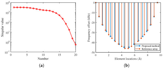
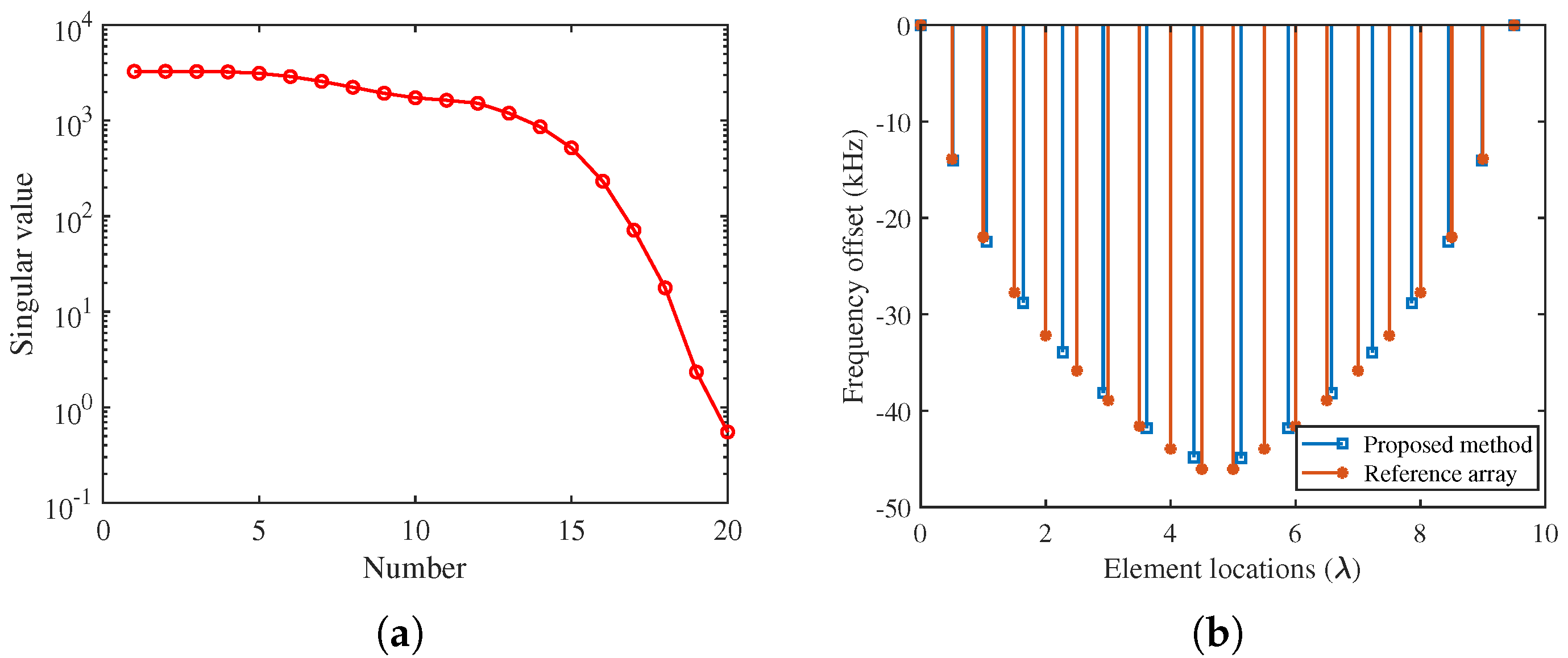
Figure 3a shows the eigenvalue spectrum of the reference pattern. It is noted that the singular values exceeding the 14th value decay rapidly, which means the very small eigenvalues can be ignored. Consequently, the reference pattern can be reconstructed with fewer array elements. In our case, the minimum estimated value is 16 at . The comparison of the element positions and frequency offsets between the original array and the obtained sparse array is given in Figure 3b. It can be observed that the minimum spacing of adjacent elements in the obtained array is greater than without specific constraints, which is conducive to reducing the mutual coupling effect. Notably, unlike other methods presented in [23], the proposed method does not force the antennas to be deployed as an integer multiple of a fixed spacing, allowing it has the potential of approximating the reference pattern with fewer elements. Besides this, the new sparse SFDA has a slightly smaller total frequency offset than the uniform SFDA.
Figure 3.
The eigenvalue spectrum and the distribution of frequency offsets and element positions. (a) The eigenvalue spectrum of the reference pattern. (b) The distribution of frequency offsets and element positions.
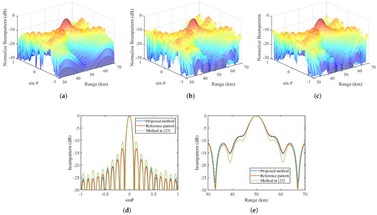
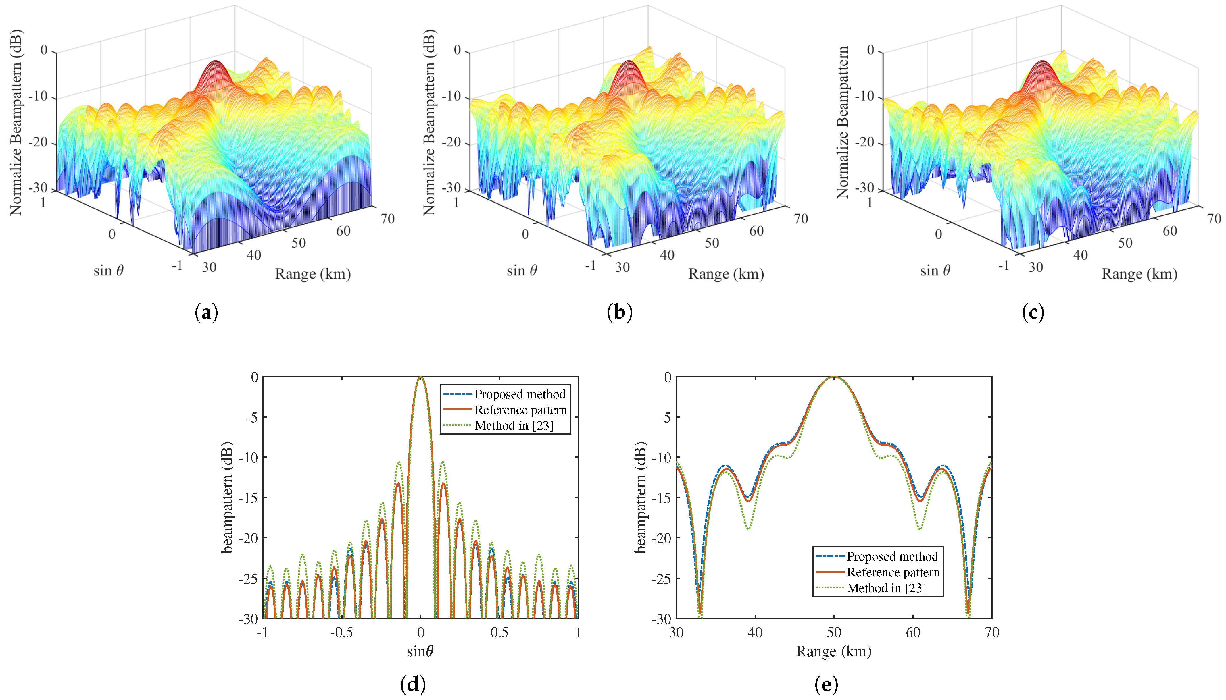
The comparison of patterns generated by different sparse SFDA methods is depicted in Figure 4. Obviously, the sparse SFDA with 16 antennas obtained by the proposed method can well approximate the cross section of reference pattern with 20 antennas, both along the angle and range dimensions. Therefore, the array elements are saved by about 20% () by the proposed method. Table 1 shows the performance comparison of different sparse SFDA synthesis methods. It can be seen that, using our method, the normalized matching error calculated by (38) is , which is better than the method presented in [23]. Moreover, the proposed method requires only about 2 s to complete the whole synthesis process in the computer with Intel Core i7-10875H CPU @ 2.30 GHz and 16GB RAM, while the algorithm in [23] requires about 440 s. Thus, the proposed method outperforms the method in [23] in terms of pattern matching accuracy and time consumption. In addition, the array positions, excitations, and frequency offsets of the obtained sparse SFDA are listed in Table 2. Generally, the dynamic range ratio of excitations, defined as the ratio between the maximum and minimum excitation amplitude, is used to evaluate the difficulty of the excitation implementation. In our work, without specific constraints, the dynamic range ratio of the excitation is 1.5418, which can be easily implemented with the available hardware conditions.
Figure 4.
The comparison of patterns generated by different sparse SFDA methods. (a) The 3D reference pattern. (b) The 3D reconstructed pattern obtained by using the method in [23]. (c) The 3D reconstructed pattern obtained by using proposed method. (d) The cross section of the pattern along angle dimension. (e) The cross section of the pattern along range dimension.
Table 1.
The performance comparison of different sparse SFDA synthesis methods.
Table 2.
The array positions, excitations, and frequency offsets of the obtained sparse SFDA.
4.2. Example 2: Beampattern Synthesis for Sparse MCFDA
In the second example, we consider the beampattern synthesis for a sparse MCFDA. The reference pattern is obtained by the two-dimensional discrete spheroidal sequence (DSS) method presented in [3]. The parameters of reference array are set as kHz, GHz and m. The visible region is set as : {6 km km, and the single target is steered to km, . Moreover, the parameters , and Additionally, the reconstructed pattern provided by the method in [25] is given for comparison.
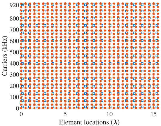
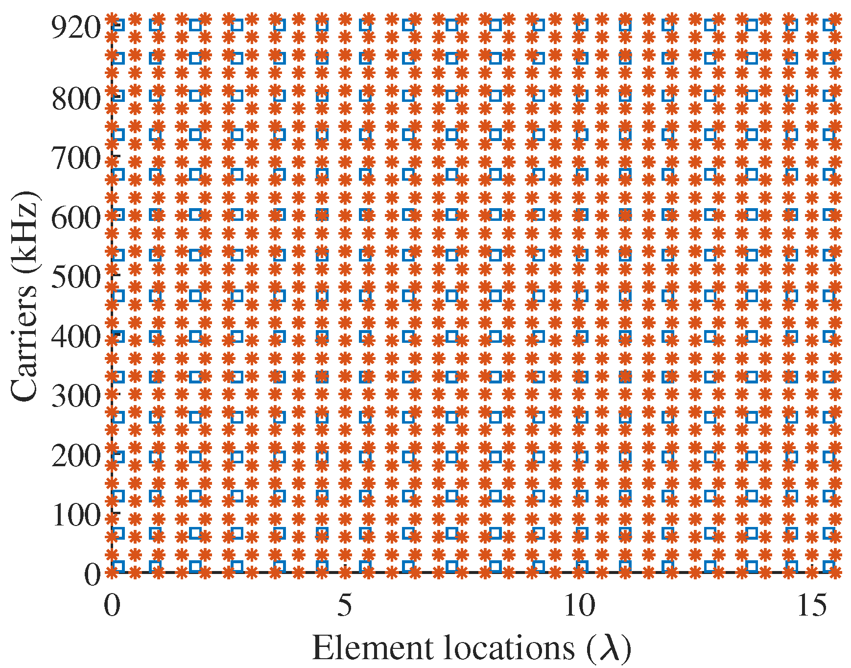
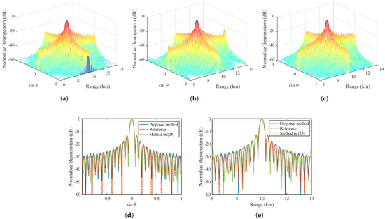
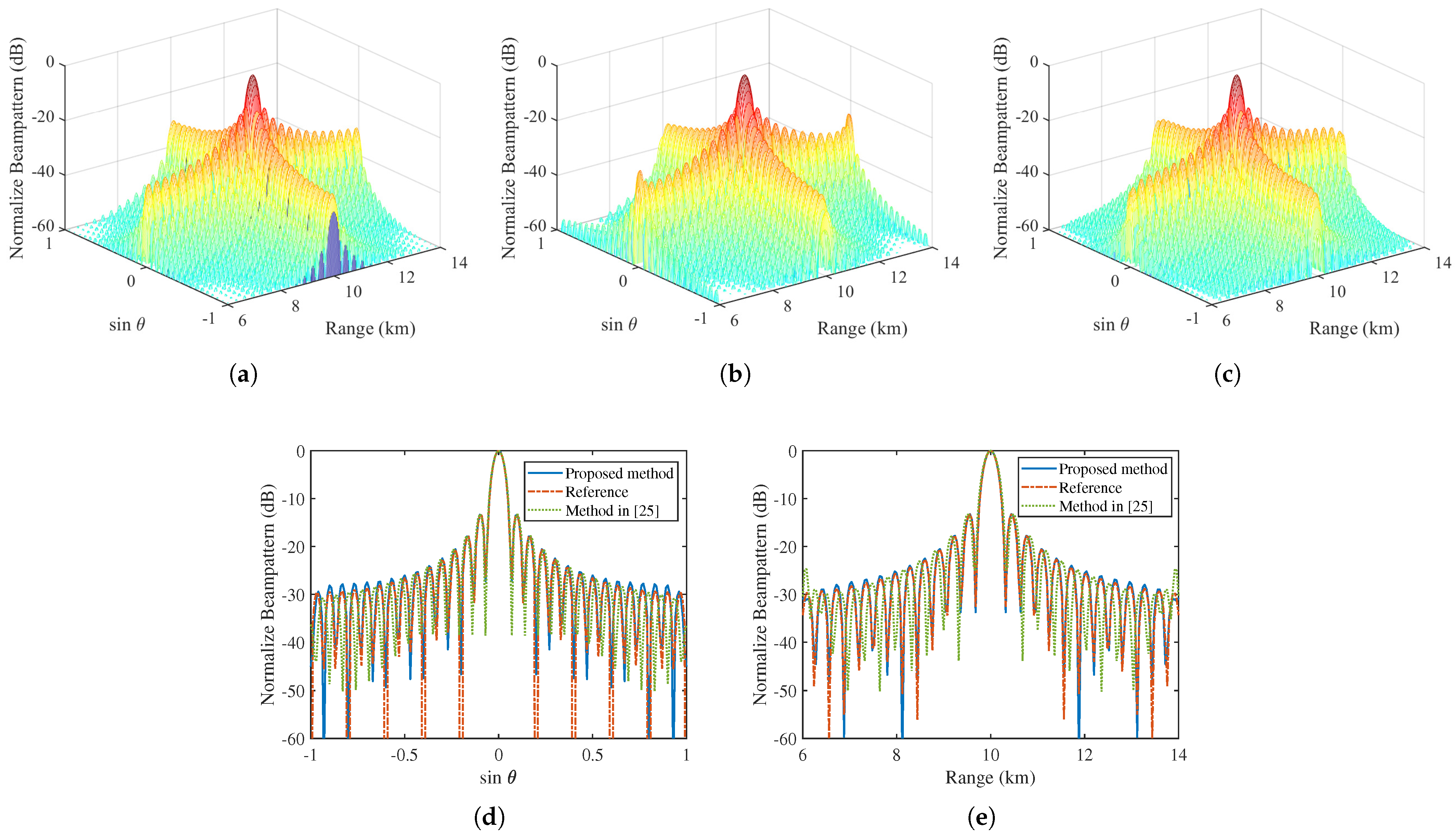
According to (19), the estimated minimum number of elements and carriers are and , respectively. This implies that we can use a sparse MCFDA with 18 array elements and 15 carriers to reconstructe the reference pattern in a given tolerance. Figure 5 gives the comparison of layout between the uniform MCFDA and obtained sparse MCFDA. It is observed that the new sparse MCFDA obtained by our method saves about 44% () of antennas and about 53% () of carriers with respect to the uniform MCFDA, which is beneficial to reduce the complexity, cost, and weight of the antenna system. Conversely, the sparse MCFDA produced by the method in [25] consists of 29 elements and 29 carriers, which saves only 9.38% of the number of elements and carriers. The comparison of patterns provided by different methods is presented in Figure 6. It can be seen that the proposed method can accurately match the reference pattern in most observation areas, with only a slight deterioration of the sidelobe level. It should be noted that the matching accuracy in the sidelobes can be improved by increasing the number of antennas and the number of carriers .
Figure 5.
The comparsion of layout between the uniform MCFDA (red asterisk) and obtained sparse MCFDA (blue square box).
Figure 6.
The comparison between the reconstructed pattern and reference pattern. (a) The 3D reference pattern. (b) The 3D reconstructed pattern obtained by using the method in [25]. (c) The 3D reconstructed pattern obtained by using proposed method. (d) The cross section of the pattern along angle dimension. (e) The cross section of the pattern along range dimension.
Table 3 shows the performance comparison of different sparse MCFDA synthesis methods. As can be seen, the normalized matching error of the reconstructed pattern generated by our method is , which is much better than the of method in [25]. It is worth mentioning that the single runtime of our method is only 0.6 s, which is also better than the 4.8 s of method in [25]. Moreover, the positions, excitations, and frequency offsets calculated by the proposed method are shown in Table 4. Note that no phase information of is provided in Table 4 since the weights are real. The dynamic range ratio of the excitations in the resultant array is 1.7464, which also can be easily implemented in practice. Similarly, the obtained sparse MCFDA yields a smaller aperture and total frequency offset.
Table 3.
The performance comparison of different sparse MCFDA synthesis methods.
Table 4.
The positions, excitations, and frequency offsets of the obtained sparse MCFDA.
5. Conclusions
In this paper, an efficient beampattern synthesis method for sparse FDA has been presented. By performing the low-rank approximation for the Hankel matrix constructed by the desired pattern samples, we can determine the minimum number of antennas for generating a reference pattern within tolerance. Then, using the MP or MEMP methods, the element positions, excitations, and frequency offsets can be obtained analytically from the low-rank version of the Hanke matrix. Besides this, two typical FDA schemes including SFDA and MCFDA are considered. The numerical examples have demonstrated that the proposed method can well approximate the desired pattern with a reduced array. In the provided examples, the entire synthesis process of the proposed algorithm only takes about a few seconds, which is very difficult for other sparse FDA synthesis methods, such as global optimization algorithms. This work concentrates more on linear FDA, and future work will focus on the development of efficient pattern synthesis methods for sparse planar FDA and circular FDA.
Author Contributions
Conceptualization, X.S. and T.H.; methodology, X.S.; software, X.S. and M.X.; validation, X.S., J.Z. and L.L.; formal analysis, X.S. and J.Z.; investigation, X.S.; data curation, X.S.; writing—original draft preparation, X.S.; writing—review and editing, Z.X and T.H.; supervision, Z.X. All authors have read and agreed to the published version of the manuscript.
Funding
This research received no external funding.
Institutional Review Board Statement
Not applicable.
Informed Consent Statement
Not applicable.
Data Availability Statement
Not applicable.
Conflicts of Interest
The authors declare no conflict of interest.
References
- Antonik, P.; Wicks, M.; Griffiths, H.; Baker, C. Frequency diverse array radars. In Proceedings of the IEEE Conference on Radar, Verona, NY, USA, 24–27 April 2006; pp. 215–217. [Google Scholar] [CrossRef] [Scilit]
- Antonik, P.; Wicks, M.C.; Griffiths, H.D.; Baker, C.J. Range-dependent beamforming using element level waveform diversity. In Proceedings of the 2006 International Waveform Diversity Design Conference, Lihue, HI, USA, 22–27 January 2006; pp. 1–6. [Google Scholar] [CrossRef] [Scilit]
- Wang, W.Q.; So, H.C.; Shao, H. Nonuniform Frequency Diverse Array for Range-Angle Imaging of Targets. IEEE Sens. J. 2014, 14, 2469–2476. [Google Scholar] [CrossRef] [Scilit]
- Lan, L.; Liao, G.; Xu, J.; Zhang, Y.; Liao, B. Transceive Beamforming with Accurate Nulling in FDA-MIMO Radar for Imaging. IEEE Trans. Geosci. Remote Sens. 2020, 58, 4145–4159. [Google Scholar] [CrossRef] [Scilit]
- Liao, Y.; Tang, H.; Chen, X.; Wang, W.Q.; Xing, M.; Zheng, Z.; Wang, J.; Liu, Q.H. Antenna Beampattern with Range Null Control Using Weighted Frequency Diverse Array. IEEE Access 2020, 8, 50107–50117. [Google Scholar] [CrossRef] [Scilit]
- Khan, W.; Qureshi, I.M.; Saeed, S. Frequency Diverse Array Radar with Logarithmically Increasing Frequency Offset. IEEE Antennas Wirel. Propag. Lett. 2015, 14, 499–502. [Google Scholar] [CrossRef] [Scilit]
- Xu, Y.; Shi, X.; Li, W.; Xu, J. Flat-Top Beampattern Synthesis in Range and Angle Domains for Frequency Diverse Array via Second-Order Cone Programming. IEEE Antennas Wirel. Propag. Lett. 2016, 15, 1479–1482. [Google Scholar] [CrossRef] [Scilit]
- Xiong, J.; Wang, W.Q.; Shao, H.; Chen, H. Frequency Diverse Array Transmit Beampattern Optimization with Genetic Algorithm. IEEE Antennas Wirel. Propag. Lett. 2017, 16, 469–472. [Google Scholar] [CrossRef] [Scilit]
- Liu, Y.; Ruan, H.; Wang, L.; Nehorai, A. The Random Frequency Diverse Array: A New Antenna Structure for Uncoupled Direction-Range Indication in Active Sensing. IEEE J. Sel. Top. Signal Process. 2017, 11, 295–308. [Google Scholar] [CrossRef] [Scilit]
- Xu, Y.; Luk, K.M. Enhanced Transmit—Receive Beamforming for Frequency Diverse Array. IEEE Trans. Antennas Propag. 2020, 68, 5344–5352. [Google Scholar] [CrossRef] [Scilit]
- Liao, Y.; Wang, J.; Liu, Q.H. Transmit Beampattern Synthesis for Frequency Diverse Array with Particle Swarm Frequency Offset Optimization. IEEE Trans. Antennas Propag. 2021, 69, 892–901. [Google Scholar] [CrossRef] [Scilit]
- Gao, K.; Wang, W.Q.; Chen, H.; Cai, J. Transmit Beamspace Design for Multi-Carrier Frequency Diverse Array Sensor. IEEE Sens. J. 2016, 16, 5709–5714. [Google Scholar] [CrossRef] [Scilit]
- Trucco, A.; Murino, V. Stochastic optimization of linear sparse arrays. IEEE J. Ocean. Eng. 1999, 24, 291–299. [Google Scholar] [CrossRef] [Scilit]
- Chen, K.; He, Z.; Han, C. A modified real GA for the sparse linear array synthesis with multiple constraints. IEEE Trans. Antennas Propag. 2006, 54, 2169–2173. [Google Scholar] [CrossRef] [Scilit]
- Donelli, M.; Martini, A.; Massa, A. A Hybrid Approach Based on PSO and Hadamard Difference Sets for the Synthesis of Square Thinned Arrays. IEEE Trans. Antennas Propag. 2009, 57, 2491–2495. [Google Scholar] [CrossRef] [Scilit]
- Pinchera, D.; Migliore, M.D.; Panariello, G. Synthesis of Large Sparse Arrays Using IDEA (Inflating-Deflating Exploration Algorithm). IEEE Trans. Antennas Propag. 2018, 66, 4658–4668. [Google Scholar] [CrossRef] [Scilit]
- Liu, Y.; Nie, Z.; Liu, Q.H. Reducing the Number of Elements in a Linear Antenna Array by the Matrix Pencil Method. IEEE Trans. Antennas Propag. 2008, 56, 2955–2962. [Google Scholar] [CrossRef] [Scilit]
- Gu, P.; Wang, G.; Fan, Z.; Chen, R. An Efficient Approach for the Synthesis of Large Sparse Planar Array. IEEE Trans. Antennas Propag. 2019, 67, 7320–7330. [Google Scholar] [CrossRef]
- Caratelli, D.; Vigano, M.C. A Novel Deterministic Synthesis Technique for Constrained Sparse Array Design Problems. IEEE Trans. Antennas Propag. 2011, 59, 4085–4093. [Google Scholar] [CrossRef] [Scilit]
- Zhang, W.; Li, L.; Li, F. Reducing the Number of Elements in Linear and Planar Antenna Arrays with Sparseness Constrained Optimization. IEEE Trans. Antennas Propag. 2011, 59, 3106–3111. [Google Scholar] [CrossRef] [Scilit]
- D’Urso, M.; Prisco, G.; Tumolo, R.M. Maximally Sparse, Steerable, and Nonsuperdirective Array Antennas via Convex Optimizations. IEEE Trans. Antennas Propag. 2016, 64, 3840–3849. [Google Scholar] [CrossRef] [Scilit]
- Pinchera, D.; Migliore, M.D.; Schettino, F.; Lucido, M.; Panariello, G. An Effective Compressed-Sensing Inspired Deterministic Algorithm for Sparse Array Synthesis. IEEE Trans. Antennas Propag. 2018, 66, 149–159. [Google Scholar] [CrossRef] [Scilit]
- Yang, Y.Q.; Wang, H.; Wang, H.Q.; Gu, S.Q.; Xu, D.L.; Quan, S.L. Optimization of Sparse Frequency Diverse Array with Time-Invariant Spatial-Focusing Beampattern. IEEE Antennas Wirel. Propag. Lett. 2018, 17, 351–354. [Google Scholar] [CrossRef] [Scilit]
- El-khamy, S.E.; Korany, N.O.; Abdelhay, M.A. A Group-Sparse Compressed Sensing Approach for Thinning Multi-Carrier Frequency Diverse Arrays. In Proceedings of the 2019 URSI International Symposium on Electromagnetic Theory (EMTS), San Diego, CA, USA, 27–31 May 2019; pp. 1–4. [Google Scholar] [CrossRef] [Scilit]
- Chen, H.; Shao, H.Z.; Wang, W.Q. Joint Sparsity-Based Range-Angle-Dependent Beampattern Synthesis for Frequency Diverse Array. IEEE Access 2017, 5, 15152–15161. [Google Scholar] [CrossRef] [Scilit]
- Sarkar, T.; Pereira, O. Using the matrix pencil method to estimate the parameters of a sum of complex exponentials. IEEE Antennas Propag. Mag. 1995, 37, 48–55. [Google Scholar] [CrossRef] [Scilit]
- Hua Yang, H.; Hua, Y. On rank of block Hankel matrix for 2-D frequency detection and estimation. IEEE Trans. Signal Process. 1996, 44, 1046–1048. [Google Scholar] [CrossRef] [Scilit]
- Zheng, M.Y.; Chen, K.S.; Wu, H.G.; Liu, X.P. Sparse planar array synthesis using matrix enhancement and matrix pencil. Int. J. Antennas Propag. 2013, 2013, 147097. [Google Scholar] [CrossRef] [Scilit]
- Shen, H.; Wang, B.; Li, X. Shaped-Beam Pattern Synthesis of Sparse Linear Arrays Using the Unitary Matrix Pencil Method. IEEE Antennas Wirel. Propag. Lett. 2017, 16, 1098–1101. [Google Scholar] [CrossRef] [Scilit]

Publisher’s Note: MDPI stays neutral with regard to jurisdictional claims in published maps and institutional affiliations. |
© 2022 by the authors. Licensee MDPI, Basel, Switzerland. This article is an open access article distributed under the terms and conditions of the Creative Commons Attribution (CC BY) license (https://creativecommons.org/licenses/by/4.0/).