


Abstract
The Automatic Identification System (AIS) is a maritime radio system that regularly broadcasts vessel data, such as the vessel’s identification, position, course and speed. For modulation, the AIS standard defines Gaussian minimum shift keying (GMSK) as an easy to implement modulation scheme with constant envelope, meaning that a GMSK complex baseband signal carries information solely in its phase. AIS does not use any forward error correction (FEC) mechanism. In this paper we propose to extend GMSK with amplitude modulation, leading to multi-amplitude Gaussian minimum shift keying (MA-GMSK). The additional modulation of the amplitude increases the spectral efficiency so that additional information, i.e., additional bits can be transmitted. We use the increased spectral efficiency to implement FEC, where we transmit the redundancy bits of a systematic channel code via the additional amplitude modulation in the proposed MA-GMSK scheme. With this approach, the proposed MA-GMSK signal can be processed by off-the-shelf AIS receivers, thus demonstrating empirical standard compatibility with the tested receivers. Based on simulations and experimental results, we propose a suitable MA-GMSK modulation parameter setting and evaluate the packet error rate (PER) performance accordingly. To verify standard compatibility, we examine the performance of commercially available AIS receivers fed with MA-GMSK signals. Using the proposed modulation and coding scheme, an advanced MA-GMSK receiver including FEC provides performance improvements up to 3 dB in the required signal-to-noise ratio (SNR) compared to state-of-the art AIS using uncoded GMSK.
1. Introduction
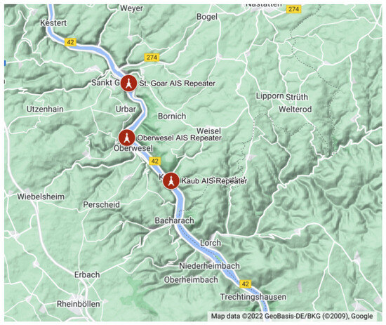
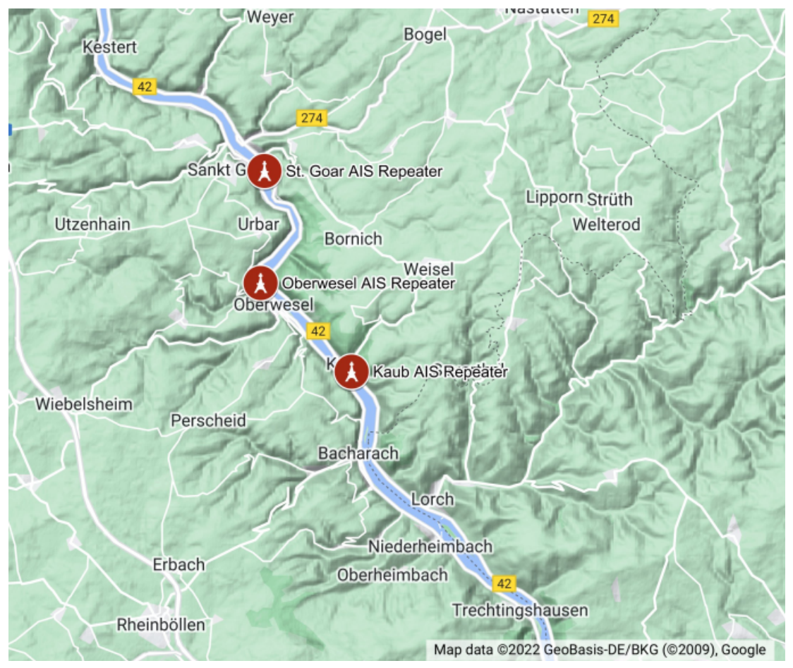
Gaussian minimum shift keying (GMSK) modulation has been used by a variety of mobile radio communication systems. Well-known standards applying GMSK modulation are the Global System for Mobile Communications (GSM) [1,2], Digital Enhanced Cordless Telecommunications (DECT) [3,4], Bluetooth Low Energy (BLE) [5] or the Automatic Identification System (AIS) [6]. GMSK modulation is applied in this variety of standards because of its low implementation complexity at both transmitter and receiver, the compact spectrum and, in particular, its constant envelope. Due to a constant signal envelope, GMSK allows power amplifiers to operate close to their optimum operating point in terms of power efficiency. In the complex baseband, a GMSK signal varies on the unit circle, thus containing information solely in its phase. Consequently, constant envelope signals like GMSK do not use the entire available complex baseband signal space. In this paper, we propose to extend GMSK with amplitude modulation, leading to multi-amplitude Gaussian minimum shift keying (MA-GMSK). The additional modulation of the amplitude increases spectral efficiency and, therefore, allows us to transmit additional information, i.e., additional bits. We retain the original modulation of the phase as with GMSK. With this, we achieve standard compatibility so that the MA-GMSK signal can be properly processed by GMSK demodulators in legacy receivers. In principle, this approach is suitable for extending any standard that includes GMSK modulation in a standard-compatible way. The increased spectral efficiency by applying MA-GMSK can be used to add more data bits in an AIS packet or to include redundant data to protect the original AIS data better by forward error correction (FEC). The AIS uses a fixed transmit power of 12.5 W and a 25 kHz channel bandwidth to transmit vessel data. This data improves situational awareness of other vessels in the vicinity. A commonly used AIS packet consists of 256 bits in total. Of these bits, 168 are payload bits. Such AIS packets are transmitted every 2–30 s depending on the speed and the turn rate of the vessel. Today, AIS is close to network saturation in high traffic areas such as ports. Repeated AIS packet transmissions increase the probability of correct reception in a certain time window. However, the missing FEC is a drawback. Especially in situations where the signal-to-noise ratio (SNR) at the receiver is low, FEC can increase the reliability to receive the other vessels’ data. On the open sea, the SNR depends on the distance between transmitter and receiver. In coastal areas or on inland waterways, signal blockage significantly reduces the SNR, even when two vessels are close together. In such areas, reliable AIS reception is important to sustain the situational awareness for both vessels. The river Rhine is the most important German waterway as a transportation link from south to north, transporting up to 80% of German ship-bound cargo. Both vessels navigating these routes and the waterways and shipping administration rely on the mandatory use of AIS. In recent years, water shortages have caused bottlenecks on waterways, increasing the risk of ship collisions [7]. Figure 1 shows the curvy river Rhine valley with hilly terrain around that makes it difficult to receive AIS messages behind curves. The proposed standard-compatible extension of AIS contains FEC, and thus increases coverage, which is particularly valuable in environments such as the one described above.
Figure 1.
The Middle Rhine is a part of Germany’s most important inland waterway and has a winding narrow course. The surrounding hilly terrain causes AIS signal blockage. Currently, three AIS repeaters are deployed along the river by the German Federal Waterways and Shipping Administration to improve AIS signal transmission along the waterway.
- Related Work
Since the beginnings of wireless data transmission, variants of continuous phase modulation (CPM) schemes have been applied in several radio communication systems. Minimum shift keying (MSK) as a special case of CPM has been studied and proposed since the 1960s [8,9,10,11]. Reasons for the popularity of MSK have been its constant envelope, its low complexity at both modulation and demodulation and its compact spectrum. Generalizations of MSK propose modulation pulses different from the rectangular pulse of MSK. As such, GMSK [12,13], which introduces Gaussian prefiltering of a rectangular pulse-shaped modulation signal, has become popular. This prefiltering leads to smoother phase transitions and, consequently, reduced out-of-band power. However, this comes at the cost of smoothing information bits over more than one symbol period, and therefore, some intersymbol interference, when demodulating with low-complexity MSK legacy receivers. A further generalization applicable to MSK concerns the introduction of multiple amplitude levels by superimposing two MSK signals with different amplitude levels. In [14], a two-level multi-amplitude minimum shift keying (MA-MSK) modulation scheme is introduced. In [15], it is shown that, like MSK, even MA-MSK is equivalent to offset quadrature amplitude shift keying (OQASK) with sinusoidal modulation pulse shape, and therefore, can be considered as a linear modulation scheme as well. The approach in [15] consequently provides MA-MSK with more than two amplitude levels. In this paper, we apply the concept of superimposing CPM signals to GMSK in order to obtain MA-GMSK with two amplitude levels. With appropriate preprocessing of data bits as introduced in [16], we achieve independent modulation of phase and amplitude, and therefore, backward compatibility to GMSK modulation. In [17], the authors proposed an optimization of CPM pragmatic channel capacity for given complexity and bandwidth efficiency. Modulation index, modulation cardinality and phase response length were used as parameters for optimization. We follow the idea in [17] and combine MA-GMSK modulator, the channel and the MA-GMSK demodulator to a pragmatic channel and evaluate its capacity in terms of mutual information. In our case, the modulation index and modulation cardinality are given due to the required standard compatibility with GMSK modulation of AIS. MA-GMSK introduces an additional parameter, which in our special case is the difference between the two amplitude levels. We optimize the amplitude level difference with respect to capacity in terms of mutual information between modulator input and demodulator output for both the standard-compatible phase modulation bit stream and the additional amplitude modulation bit stream. We obtain these mutual information by Monte-Carlo simulations for binary data packets of finite length according to the AIS standard [6].
- Organization of this Paper
In Section 2, we introduce MSK and GMSK modulation. GMSK modulation is the main building block of MA-GMSK. MA-GMSK modulation as a weighted superposition of two GMSK modulated signals is introduced in Section 2.3. In Section 3, we present maximum a-posteriori (MAP) demodulation methods for GMSK. These demodulation schemes provide soft-decision values for each bit in form of log-likelihood ratios (LLRs). These LLRs are used as input for soft-decision for a FEC decoding algorithm. MA-GMSK modulation introduces a parameter —we define it as the amplitude modulation difference—which controls the Euclidean distance of the two amplitude levels of our MA-GMSK modulation scheme. In Section 4, we investigate the influence of the amplitude modulation difference on information throughput for MA-GMSK modulation. We aim to identify an amplitude modulation difference , which maximizes this mutual information. We measure information throughput in terms of mutual information between transmitted bits and the corresponding LLR at the output of the MA-GMSK modulator. An approach how to measure mutual information from LLRs is shown in Appendix A. In Section 5 we describe how to modify the AIS by FEC in a standard-compatible manner. Standard compatibility means that after this modification, a commercially available AIS receiver is still able to work within specifications, even when operated with the modified AIS. An advanced AIS receiver, however, exploits the additional FEC capabilities for improving the AIS packet error rate (PER) performance. Appropriate FEC coding schemes, in particular turbo coding and convolutional coding, are introduced in Section 5.2. In Section 6, we evaluate the AIS PERs when applying appropriate demodulation and decoding at an advanced AIS receiver. In order to verify standard compatibility, we investigate the packet error rate (PER) performance of common-off-the-shelf AIS receivers, which are fed with a multi-amplitude Gaussian minimum shift keying (MA-GMSK) signal. In Section 7, we summarize this study and draw the conclusions.
2. Continuous Phase Modulation
The complex-valued base band representation of a CPM modulated signal is defined as [16]
and, by definition, has a constant envelope . Its phase
is varying continuously in time and carries information of the transmitted bits . One data bit is transmitted in a time interval of duration T. The parameter h is called the modulation index. The phase response
is constructed by integration from a frequency response pulse , where for and . The case for , meaning that the entire phase change for one information bit occurs during one time interval of duration T, is called full response CPM. The alternative, where for , is called partial response CPM.
2.1. Minimum Shift Keying (MSK)
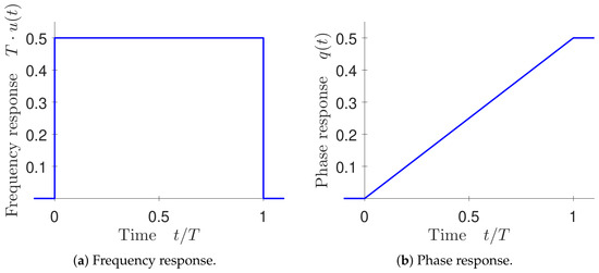
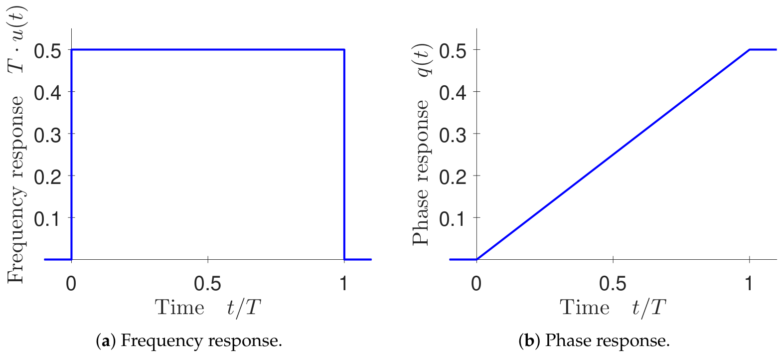
A well-known representative of a full response CPM modulation scheme is MSK. Its modulation index is , meaning that the phase of the baseband signal changes by , depending on the corresponding information bit . The frequency response pulse for is constant during the time interval . This leads to a phase response which is linearly increasing from to . Figure 2 shows frequency and phase response for MSK. Due to its discontinuous frequency response, MSK shows a broad power density spectrum (PDS). One approach to get a more narrow PDS is to low-pass filter the rectangular frequency response pulse . This filtering results in smoother frequency and phase response functions. However, they last over more than one symbol interval T, leading to partial response CPM. One representative of a partial response CPM scheme is Gaussian minimum shift keying (GMSK), which we are going to introduce in the following section.
Figure 2.
MSK: frequency and phase responses.
2.2. Gaussian Minimum Shift Keying (GMSK)
Gaussian minimum shift keying (GMSK) is a representative of the partial response CPM schemes. The frequency response pulse
of GMSK is obtained by passing a rectangular pulse
of duration T through a Gaussian low-pass filter with impulse response
where B is the 3 dB-bandwidth. For notational convenience, we consider the pulses and to be symmetric with respect to . The Gaussian low-pass filter impulse response and consequently also the frequency response pulse have an infinite temporal expansion. In practical systems, such a frequency response pulse is not realizable. Depending on the normalized bandwidth , most of the energy of the frequency response pulse is concentrated within an interval of L symbols. This interval has a duration of . For practical realization, we crop the symmetric frequency response pulse to a time interval of , normalize such that the cropped pulse integrates to and shift the cropped and normalized pulse by in order to get a causal frequency response pulse
with normalization constant
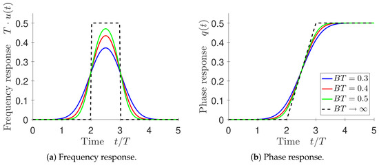
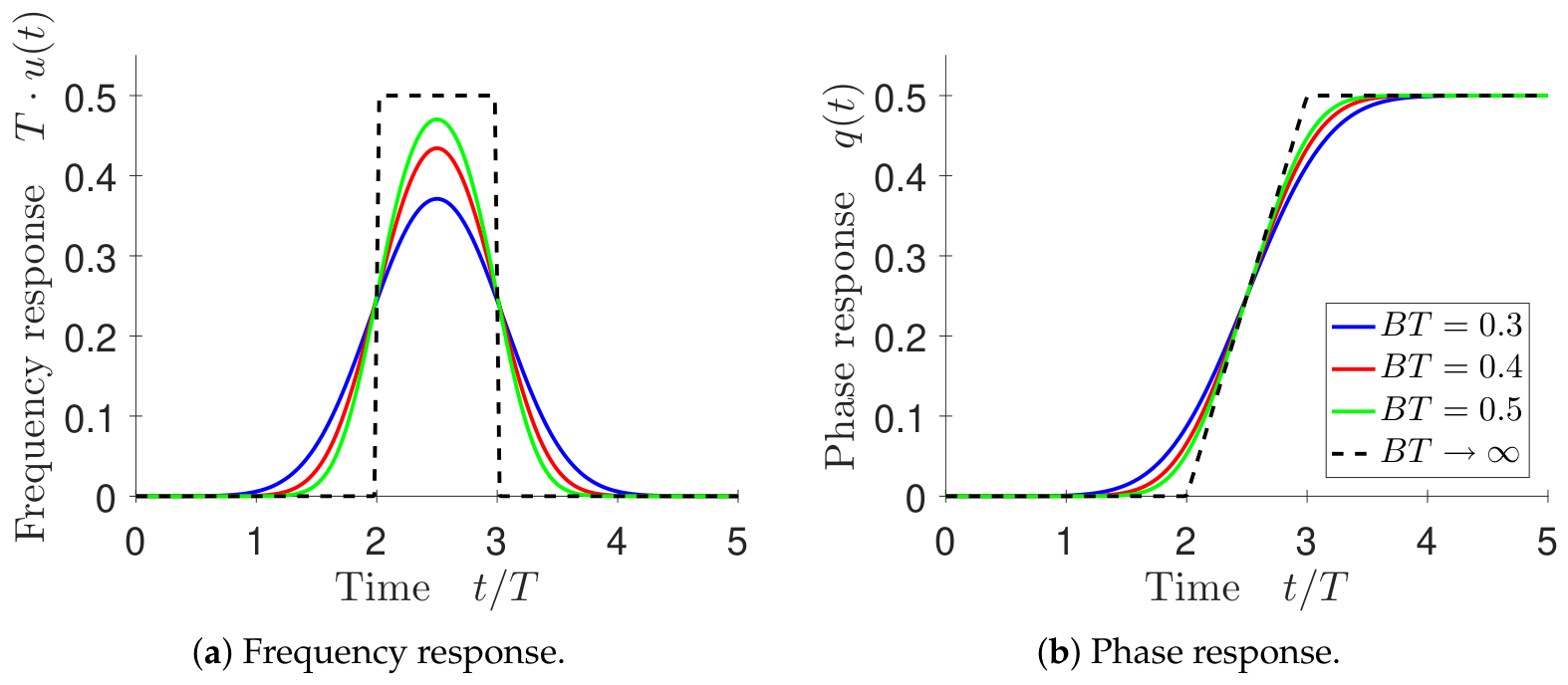
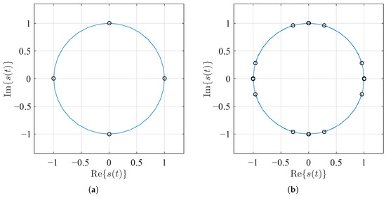
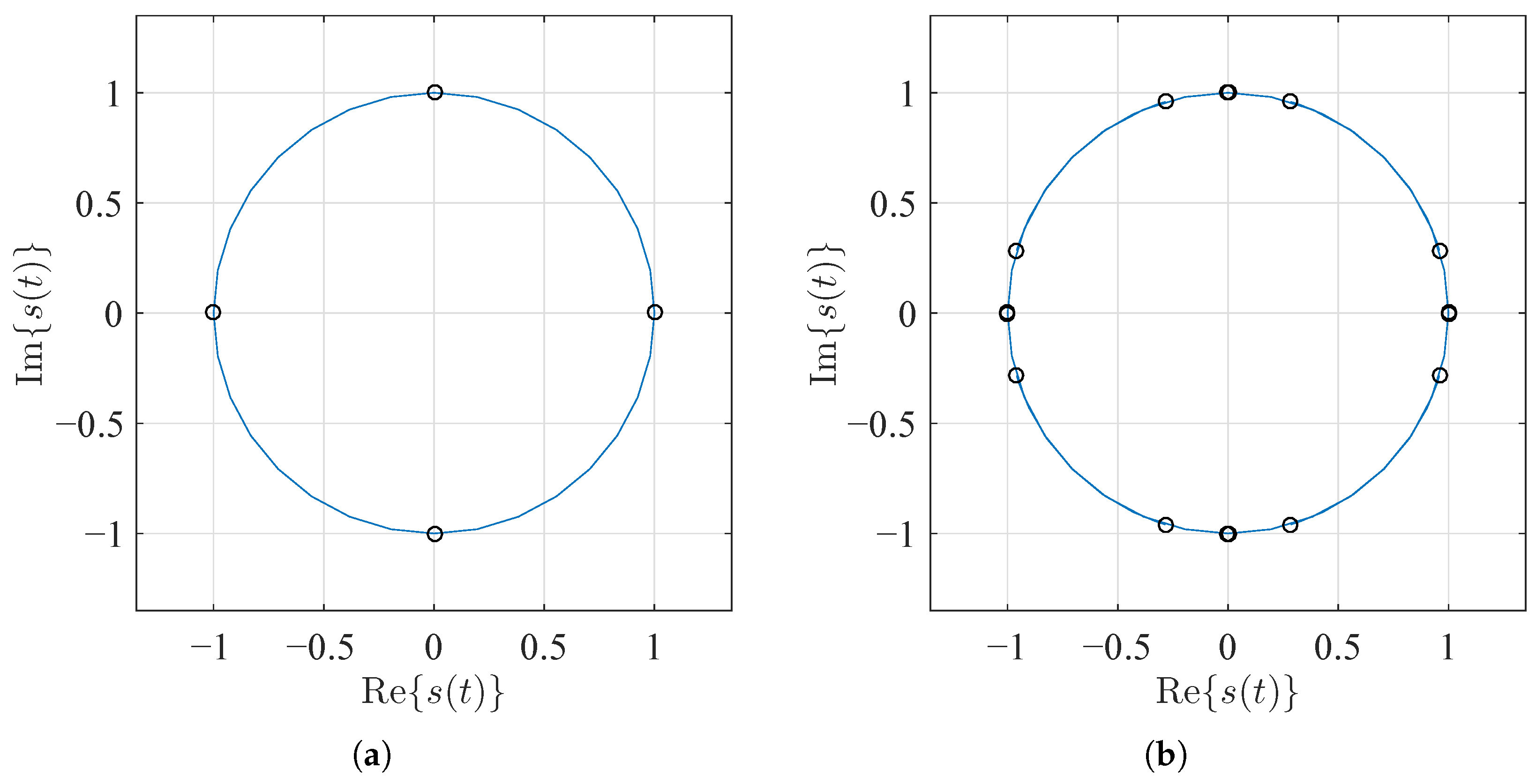
The phase response is calculated according to (3). Figure 3 shows the frequency response pulses and the corresponding phase responses for and different normalized Gaussian low-pass filter bandwidths . For , the GMSK frequency and phase responses are equivalent to MSK. Figure 4 shows a MSK and a GMSK signal in the complex signal space. Black markers indicate the MSK resp. GMSK signal at integer multiples of symbol time T. At those time instants, the MSK signal states show four dedicated values . We observe inter-symbol interference for GMSK due to its partial phase response.
Figure 3.
GMSK: frequency and phase responses for different normalized Gaussian low-pass filter bandwidths BT and phase response length L = 5.
Figure 4.
Signal space diagrams for MSK and GMSK. (a) MSK; (b) GMSK with BT = 0.4 and phase response length L = 5.
2.3. Multi-Amplitude GMSK
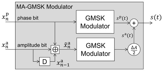
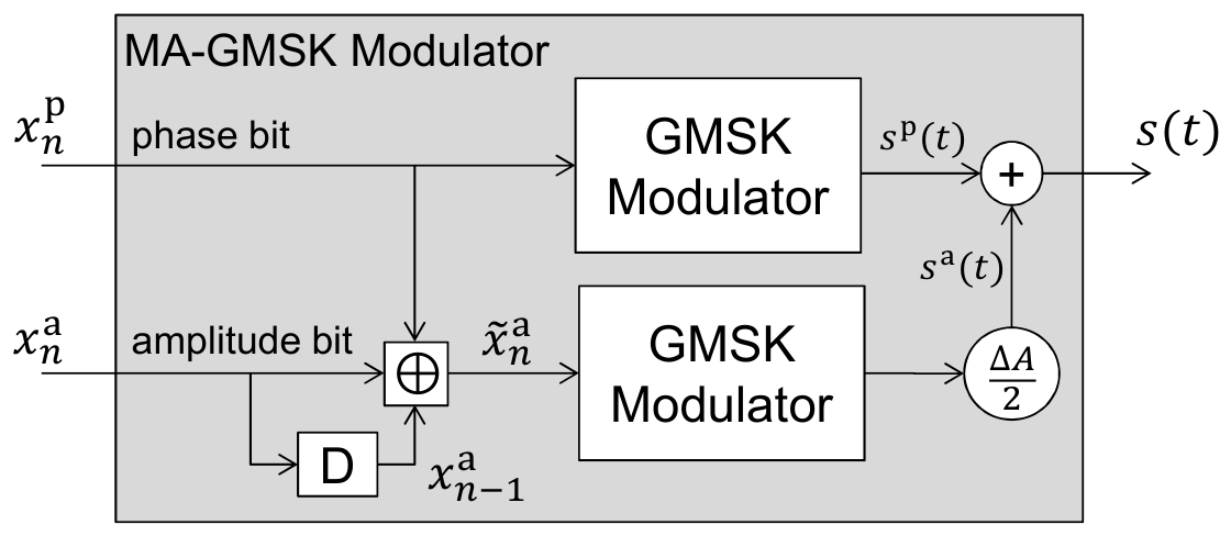
GMSK is a constant envelope modulation scheme. The transmitted information is contained in the phase of a GMSK signal. A constant envelope signal allows power amplifiers at a transmitter to operate close to their optimum operating point with respect to power efficiency. On the other hand, a constant envelope signal does not make the best possible use of the signal space. Our aim is to apply amplitude modulation as a further degree of freedom for the transmission of additional information, while keeping the original modulation of the phase as undistorted as possible. Extending a system standard by applying MA-GMSK but maintaining the original phase modulation properties of GMSK provides standard compatibility. Rather than just multiplying a GMSK signal with a real valued amplitude modulation function, we construct an MA-GMSK signal by an appropriate superposition of 2 component GMSK signals as shown in the block diagram in Figure 5. Constructing the signal by superposition, offers the advantage that the PDS of the MA-GMSK signal remains unchanged compared to a GMSK signal. So, compliance with given spectral masks is inherently achieved by that construction. In the following we focus on a binary modulation of the GMSK signal’s amplitude. With that we can transmit an additional data bit during one symbol time interval of length T. As in classical GMSK, the approach shown in Figure 5 uses a binary data symbol , referred to as the phase bit, as input of a GMSK modulator, which provides a complex valued GMSK baseband signal of constant amplitude 1. The idea is now to use a second GMSK modulator, which provides a GMSK signal with a smaller amplitude of compared to the phase bit GMSK modulator. This GMSK modulator runs either in-phase or out-of-phase with a phase shift of , compared to the phase bit GMSK modulator, depending on the amplitude bit . Assume that data transmission starts at time index with identical internal states of the GMSK modulators, meaning they are running in-phase at the beginning. The relative signal phase between and changes from in-phase to out-of-phase and vice versa whenever the amplitude bit changes its value. In order to achieve this we generate the input to the amplitude GMSK modulator as
with and the modulo-2 addition ⊕ as defined in Table 1. The MA-GMSK signal
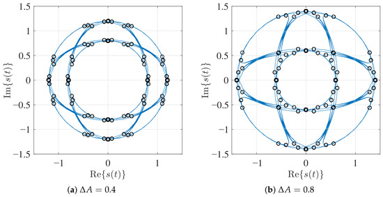
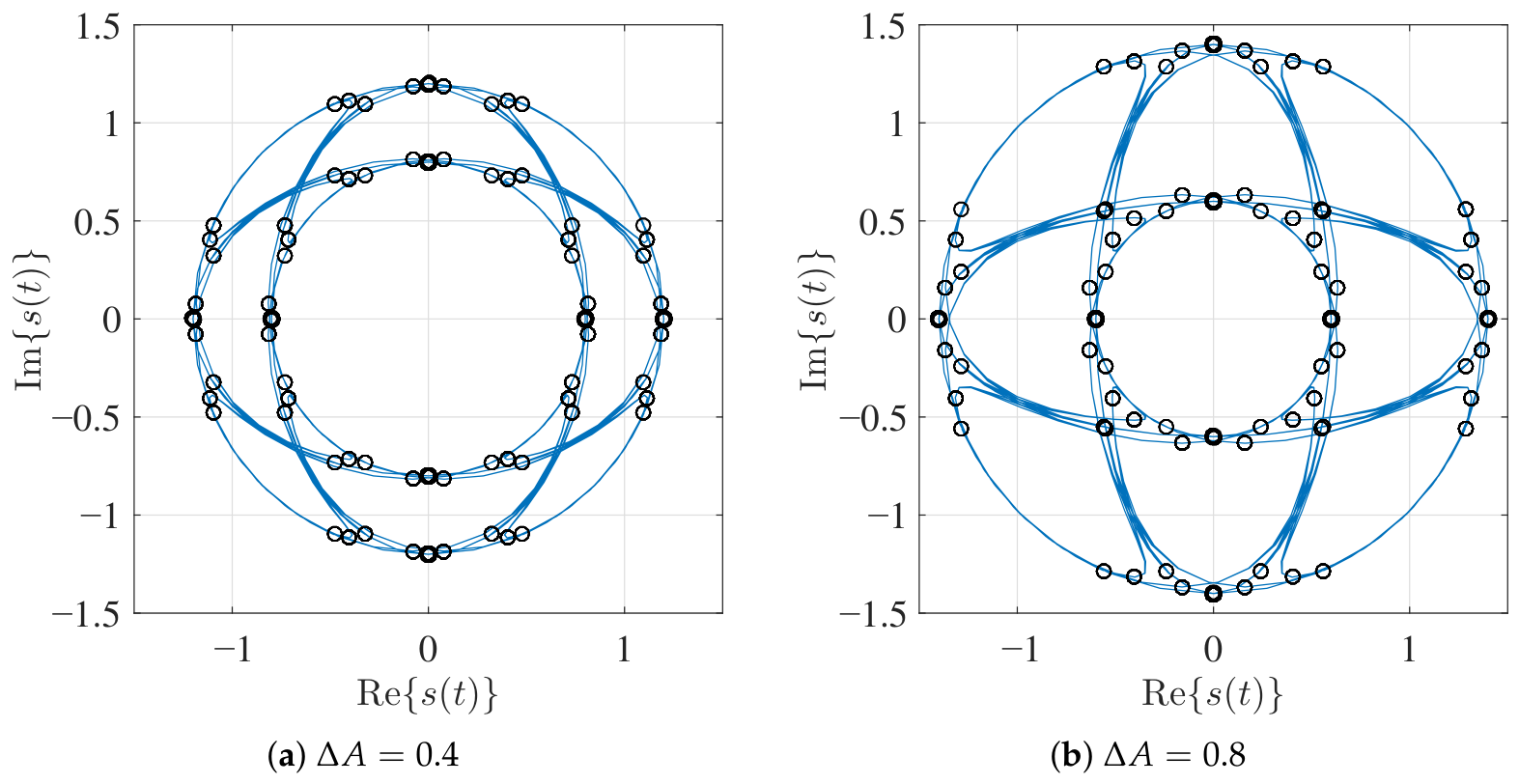
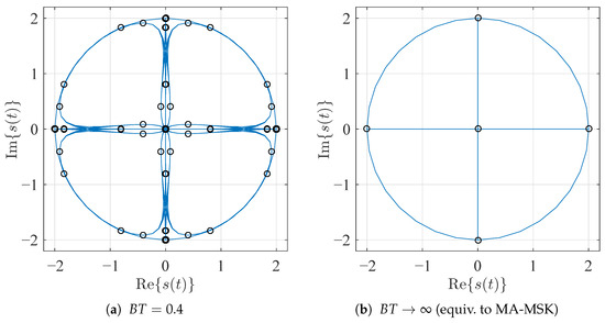
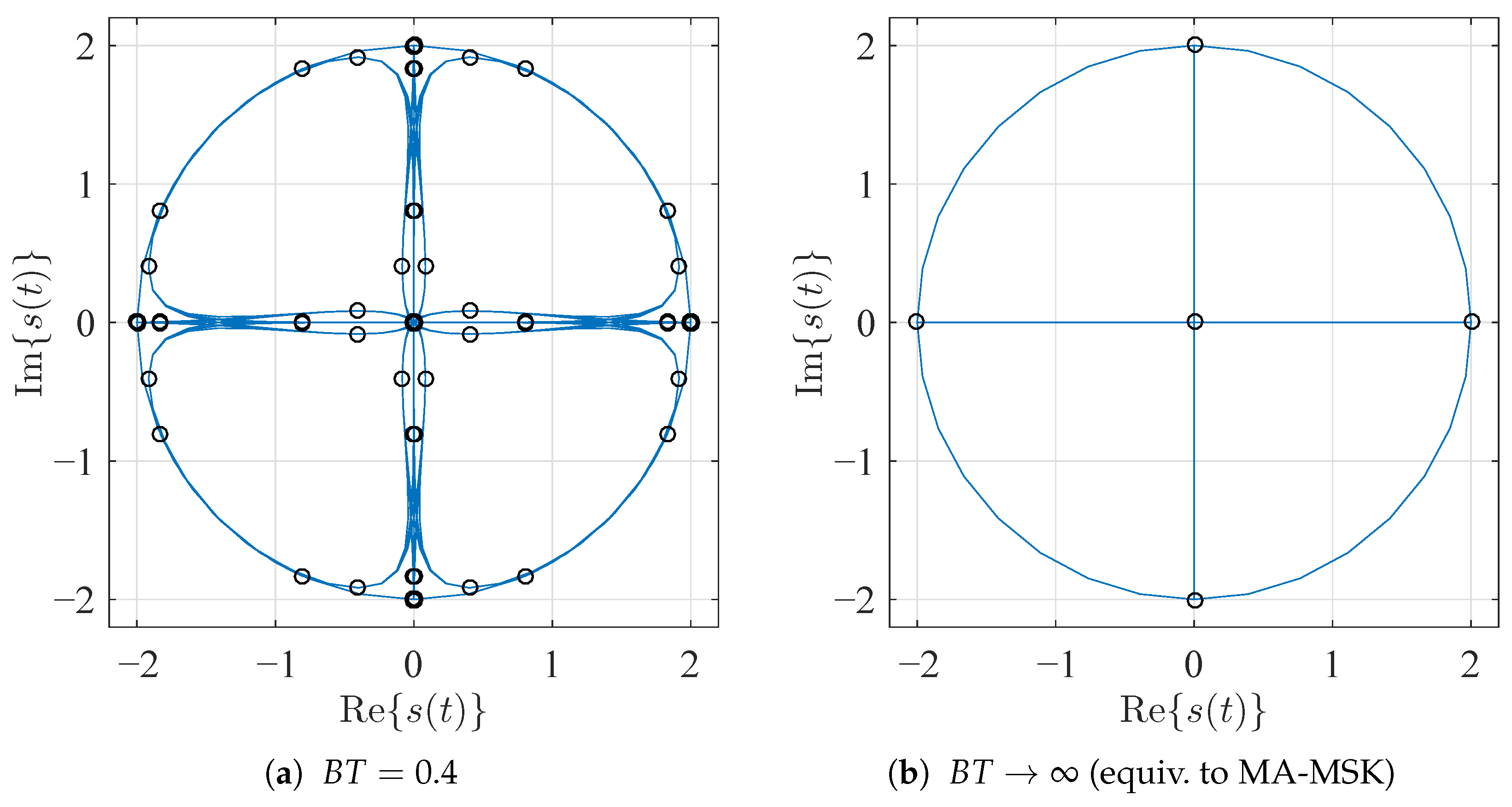
is shown in Figure 6 in the complex signal space for different amplitude modulation differences . From Figure 6 we can clearly observe 2 amplitude levels and the transitions between them. The black markers indicate the MA-GMSK signal states at integer multiples of symbol time T. The amplitude modulation difference is the difference of the 2 amplitude levels. Compared to GMSK, we observe additional inter-symbol interference also in amplitude direction. Note the MA-GMSK signal according to (10) is not normalized to an average power of 1. However, as detailed in Section 6.1, the signal is explicitly scaled to unit average power prior to performance evaluation to ensure a fair comparison. For , MA-GMSK is equivalent to GMSK as shown in Figure 4b. In this case, the MA-GMSK modulator signal does not depend on amplitude bit . For the maximal value , the inner amplitude level collapses to the origin of the complex signal plane. Figure 7a shows the signal space diagram for MA-GMSK with and . We can observe the collapsed signal states at the origin but also significant inter-symbol interference. For comparison, Figure 7b shows the signal space diagram for and , which means that the MA-GMSK component modulators are full response MSK modulators. In this case, the four outer amplitude level states and the collapsed inner amplitude levels are clearly visible.
Figure 5.
MA-GMSK modulator composed of 2 GMSK modulators.
Table 1.
Table of values for binary (modulo-2) addition ⊕ for different binary alphabet notations.
Figure 6.
Signal space diagrams for MA-GMSK with BT = 0.4 and different amplitude modulation differences .
Figure 7.
Signal space diagrams for MA-GMSK with maximum amplitude modulation difference .
3. MA-GMSK Demodulation
We sample the complex valued baseband signal at the output of the MA-GMSK modulator with a rate of K samples per symbol time T. The transmitted complex valued baseband samples are . The MA-GMSK modulator provides a one-to-one mapping between a -bit data sequence and the complex valued baseband sequence of length . At the receiver side, we observe the complex valued baseband sequence of length . We assume an additive white Gaussian noise (AWGN) channel, so the received complex valued baseband signal samples
are corrupted by complex valued AWGN with zero mean and variance . So, the likelihood function is
3.1. MAP Demodulation
Following the symbol-by-symbol MAP approach [18,19], the MA-GMSK demodulator calculates a LLR
for each of the bits in data sequence given the received complex baseband sequence . Set contains all possible data sequences at the input of the MA-GMSK modulator. The cardinality of set is . By applying Bayes’ rule, (13) can be rewritten to
The first right-hand side term of (14) is the a priori LLR for data bit . It equals 0 for data bits with equal probability . Assuming statistical independence of the channel noise process, the likelihood function can be written as , which yields
3.2. Log-MAP Demodulation
In (15), many likelihoods are close to zero, especially in good channel conditions with low noise. This can cause numerical inaccuracies when calculating the sum-product terms. In order to prevent such numerical problems, it is preferable to use logarithmic likelihoods. Thus, we aim to bring the logarithm operation inside the sum-product in (15). For the product, this can be achieved by applying the logarithmic calculus rules. Exchanging the logarithm operation and summation, however, is not that straightforward. Following [19], we express the logarithm of a sum of probabilities and
by taking the maximum of the logarithmic probabilities and applying a correction term. For more than two addends, which is very likely the case in (15), we apply (16) recursively. Similar to [20], we abbreviate this operation with a ‘boxsum’
and rewrite (15) to
This version of MAP using log-likelihoods is called logarithmic MAP (Log-MAP).
3.3. Max-Log-MAP Demodulation
4. Optimizing MA-GMSK
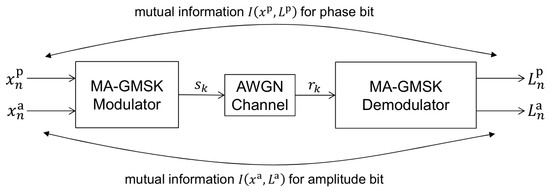
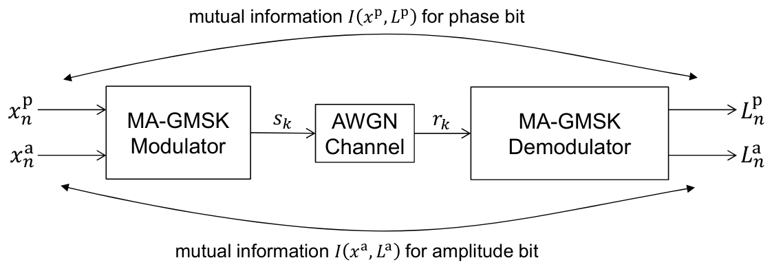
The MA-GMSK modulator, introduced in Section 2.3, provides us with the opportunity to transmit 2 bits at one time interval of duration T. One of these bits—the ‘phase bit’ in Figure 5—determines the phase of the complex valued signal , similar to classical GMSK modulation. The ‘amplitude bit’ influences the amplitude of . The amount of information, which we can transfer via the ‘phase bit’ and the ‘amplitude bit’, respectively, depends on the MA-GMSK amplitude modulation difference . For a small , the Euclidean distance between the inner and the outer signal constellation symbols is small, leading to higher error probabilities, and therefore, lower information transfer capabilities. In particular, for , the symbols at different amplitude levels become less and less distinguishable, leading to an amplitude bit error rate which tends to 0.5 and a corresponding information transfer which goes to zero. The Euclidean distances between the different phase states of the symbols approach those of classical GMSK. With increasing , the Euclidean distance between symbols with different amplitude levels increases, leading to lower amplitude bit error rate and corresponding higher information transfer in the amplitude bit. The Euclidean distances for symbols with different phase states decrease for the inner ring of symbols. This leads to an increased phase bit error rate, and therefore, reduced information transfer for the phase bit. Therefore, if we increase from 0 to 2, the mutual information for the amplitude bit monotonically increases, while the mutual information for the phase bit monotonically decreases. This increase, respectively, decrease in mutual information is not proportional to . Therefore, we can expect an optimal which maximizes the sum of mutual information for the phase bit and the amplitude bit. We measure mutual information between N transmitted phase bits and their corresponding LLRs , as well as between N amplitude bits and at the receiver side as shown in Figure 8. A bit data sequence
is fed into a MA-GMSK modulator. Signal at the output of the MA-GMSK modulator is sampled with a rate of samples per symbol time T providing a complex valued baseband transmit sequence
of length . The received signal samples
are corrupted by AWGN with zero mean and variance . The SNR
at the receiver input depends on signal energy , noise power density and the oversampling factor K, i.e., the number of samples per symbol time, since the Nyquist bandwidth and the AWGN power . We calculate the mutual information between N phase bits and LLRs respectively the mutual information between N amplitude bits and LLRs according to [21]
Figure 8.
Measuring mutual information between transmitted bits and MA-GMSK demodulator output.
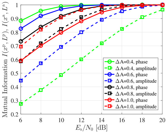
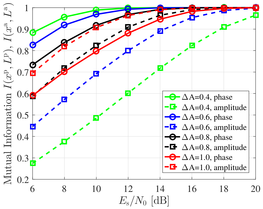
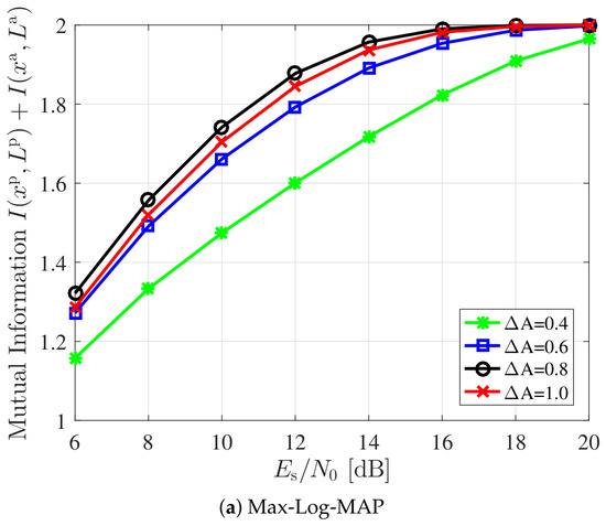
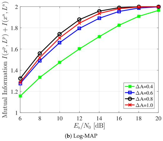
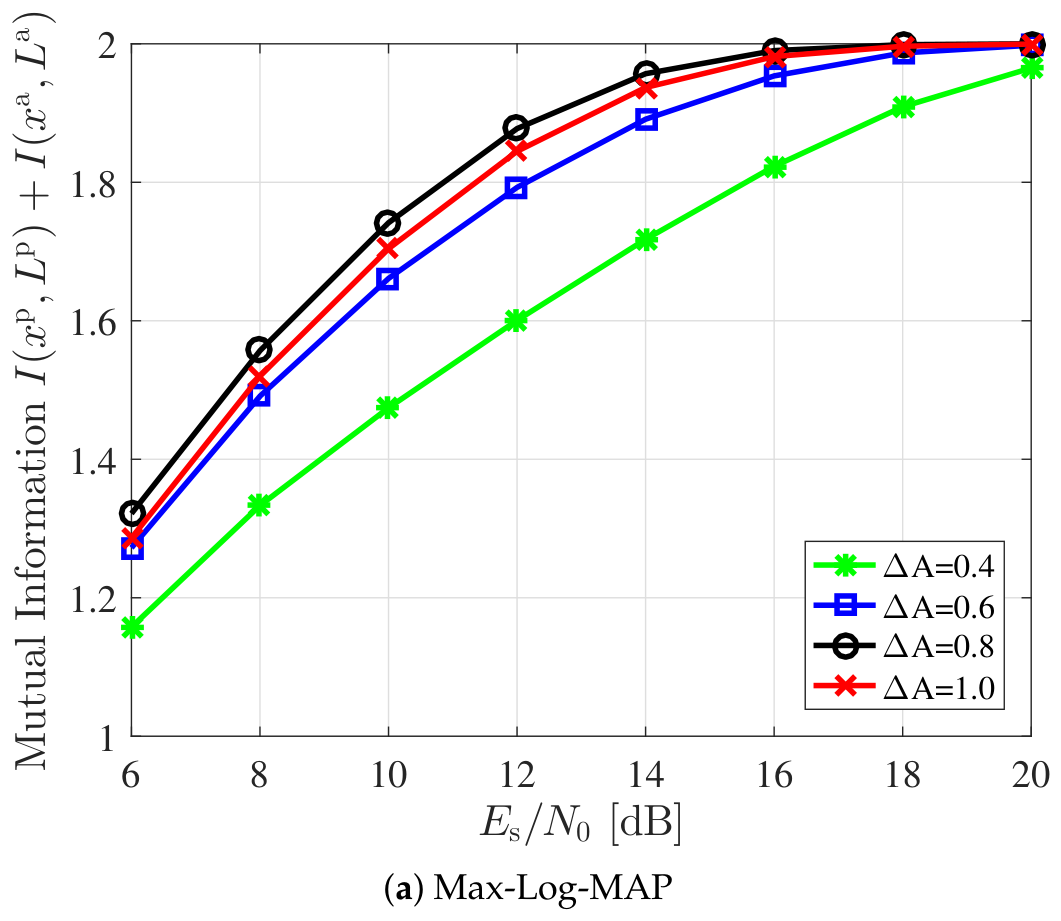
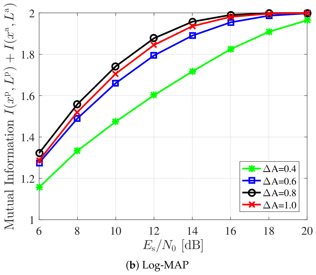
For the derivation see Appendix A and (A8) therein, where for equally probable data bits . Figure 9 shows these individual mutual information versus for a Max-Log-MAP MA-GMSK demodulator according to (20). With increasing amplitude modulation difference , the mutual information for the phase bit decreases whereas the mutual information for the amplitude bit increases. This confirms our discussion at the beginning of this section. Figure 10a shows the total mutual information versus for Max-Log-MAP demodulation. We observe that the total mutual information is maximized for an amplitude modulation difference of for the entire range of considered . For comparison Figure 10b shows the total mutual information for Log-MAP demodulation. Comparing optimal Log-MAP and sub-optimal Max-Log-MAP demodulation, we observe that performance differences in terms of mutual information are negligible. This justifies the application of computationally lower complex Max-Log-MAP demodulation.
Figure 9.
Individual mutual information between transmitted phase resp. amplitude bit and the corresponding Max-Log-MAP MA-GMSK demodulator outputs versus .
Figure 10.
Total (sum) mutual information between transmitted phase resp. amplitude bit and the corresponding MA-GMSK demodulator outputs versus .
5. Application of Standard-Compatible Error Protection to the AIS
AIS is a self organized time division multiple access (TDMA) (SO-TDMA) system [6]. One TDMA frame of 60 s length is divided into 2250 slots, each of length 26.67 ms. Within a slot, a 256-bit data packet is transmitted at a rate of 9600 using GMSK modulation. Figure 11 shows the structure of an AIS data packet. One AIS data packet contains 168 data bits, followed by 16 cyclic redundancy check (CRC) bits for error detection. Besides the CRC bits, no further redundancy bits, which could be used for error correction, are transmitted.
Figure 11.
256 bit AIS data packet.
5.1. Approach
In order to correct errors after transmission of an AIS data packet, we apply FEC. We use a rate-1/2 systematic channel code for encoding the data part of an AIS data packet. As shown in Figure 11, the AIS data packet part consists of 168 data bits and 16 CRC bits. Since we use a systematic code, the 184 data bits themselves appear in the encoded bit sequence together with further 184 redundancy bits. For modulation, AIS data packets according to Figure 11 are fed as phase bits into a MA-GMSK modulator, such as shown in Figure 5. These phase bits modulate the phase of the transmit signal and can be demodulated by a legacy AIS receiver, thus, demonstrating empirical standard compatibility with the tested receivers. The 184 FEC redundancy bits are used as the amplitude bits of the MA-GMSK modulator. The corresponding amplitude bits of the AIS data packet overhead part are set to . This results in transmitting the AIS data packet overhead part with high-amplitude levels in order not to impair synchronization. The 256 bits, which are fed as the amplitude bits into the MA-GMSK modulator are depicted in Figure 12.
Figure 12.
The 256 amplitude bits for MA-GMSK modulation of an AIS data packet.
5.2. Coding Schemes
We require a rate-1/2 systematic channel code for encoding the 184 data and CRC bits of an AIS data packet. Subsequently, we evaluate 2 different FEC schemes, namely the 3rd Generation Partnership Project (3GPP) Long Term Evolution (LTE) turbo code [22] and a recursive terminated convolutional code.
5.2.1. Turbo Coding
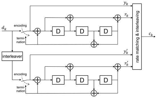
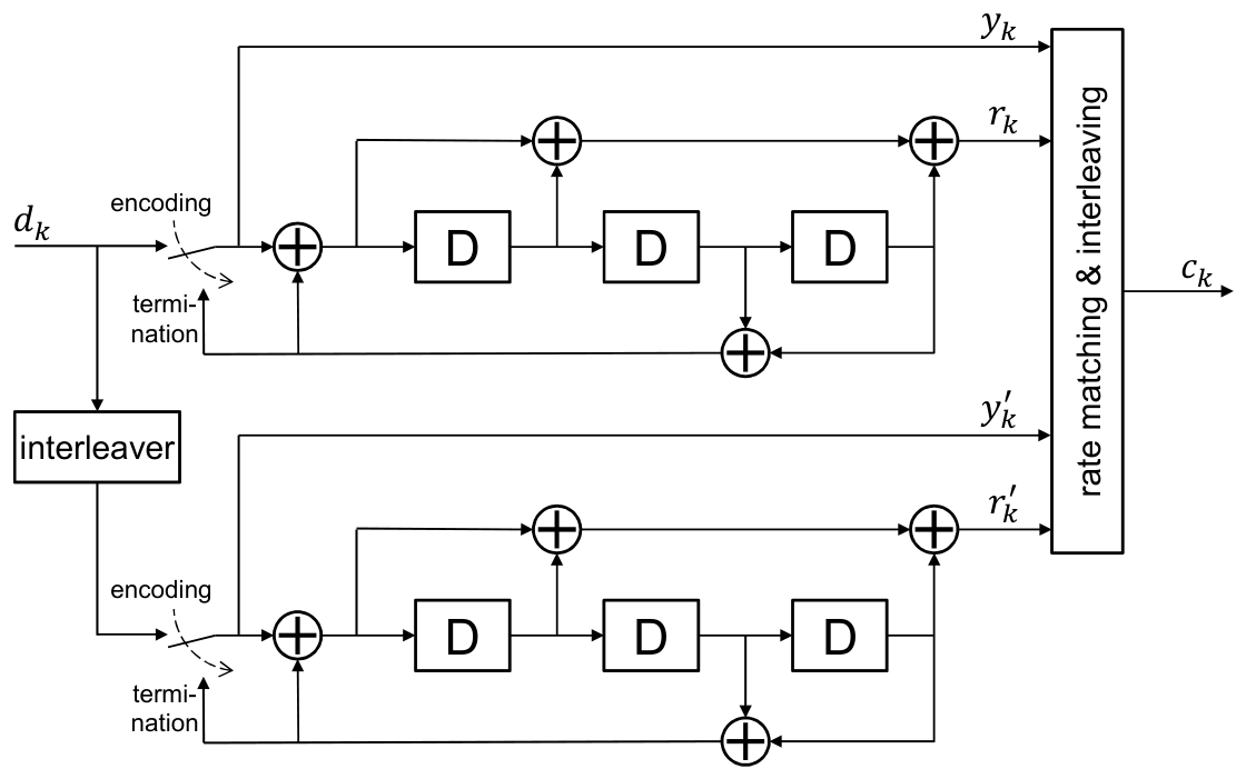
We use the 3GPP LTE turbo code as specified in [22]. The LTE turbo code is a parallel concatenated convolutional coding scheme as shown in Figure 13. It consists of two systematic recursive 8-state convolutional codes with generator polynomials in octal notation, an internal interleaver for parallel code concatenation and a rate matching and interleaving block. The turbo encoder, shown in Figure 13, starts with encoding the K data bits with the switches in position “encoding”, providing 3-bit streams , and for . The initial states of the convolutional encoders, i.e., the memory blocks “D” are set to zero. Stream contains the data bits. and contain redundancy bits. After data encoding, the switches are changed to position “termination” for 3 more encoding clock cycles. This puts the convolutional encoders to zero state. The 3 termination cycles produce further 12 termination bits , , and , , which are appended to the bit streams as follows:
Figure 13.
LTE turbo encoder.
Each of these sequences are interleaved by corresponding interleavers . The interleaved sequences are denoted as
The turbo code word is constructed by aggregating the sequences , where the bits of sequence are the first bits of turbo code word . Interleaving, aggregation of the redundancy sequences and as well as matching the turbo code word length N for achieving a code rate of are described in [22]. Note the first bits of a turbo code word contain the K data bits in an interleaved order, defined by interleaver . However, we require the data bits in unchanged order for standard-compatible MA-GMSK. Therefore, we deinterleave the first turbo code bits, i.e., , using the inverse interleaver . The first K bits of the deinterleaved sequence are the data bits , which we use as phase bit input of the MA-GMSK modulator. Applying this coding scheme to encode the data part of an AIS data packet, the number of data bits is and the turbo code word length .
5.2.2. Convolutional Coding
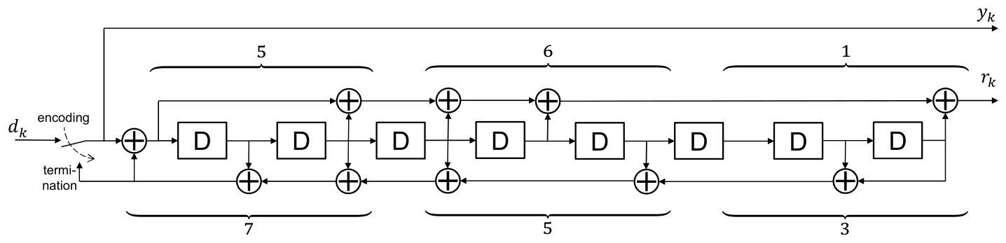
Figure 14 shows the block diagram of a 256-state (memory 8) recursive systematic convolutional code with generator polynomials in octal notation. Encoding of K data bits starts with the switch in position “encoding”, providing 2 bit streams and for . The initial states of the memory blocks ‘D’ are set to zero. After data encoding, the switches are changed to position “termination” for 8 more encoding clock cycles. This puts the convolutional encoders to zero state and produces further 16 termination bits and . The redundancy and termination bits are interleaved by an interleaver , which yields the sequence
Figure 14.
Memory 8 recursive systematic convolutional encoder.
The first bits of sequence build the redundancy part of the length-N convolutional code word
The first bits of the convolutional code word are the data bits . We use them as phase bit input for standard-compatible MA-GMSK modulation. The redundancy bits are used as amplitude bit input of the MA-GMSK modulator.
5.3. Transmitter Hardware Considerations and PAPR
While standard GMSK provides a constant envelope (0 dB Peak-to-Average Power Ratio), the introduction of amplitude modulation in MA-GMSK inherently increases the PAPR. For the practically recommended amplitude modulation difference of , the PAPR of the MA-GMSK baseband signal is approximately 1.67 dB.
The impact of this PAPR depends heavily on the transmitter hardware. For legacy AIS transmitters utilizing highly non-linear (Class C) saturated amplifiers, the transmitter must be backed off by 1.67 dB to prevent non-linear clipping of the amplitude redundancy bits. While this slightly reduces the average transmit power, the exponential coding gains provided by FEC in maritime multipath fading channels far exceed this 1.67 dB penalty, yielding a net improvement in link reliability.
However, for modern maritime transceivers, particularly those designed to support the VHF Data Exchange System (VDES), this PAPR is negligible. VDES transceivers are required to transmit higher-order modulations such as -QPSK, 8-PSK, and 16-QAM, which exhibit PAPRs in excess of 3 to 5 dB. Consequently, these modern transceivers are already equipped with linear power amplifiers (often utilizing Class AB architectures, envelope tracking, or digital pre-distortion). When MA-GMSK is deployed on such modern hardware, the 1.67 dB amplitude fluctuation is natively supported without requiring further power back-off, allowing the system to harvest the full theoretical FEC coding gain.
5.4. Computational Complexity
The introduction of MA-GMSK with FEC distributes computational complexity asymmetrically across the system. At the transmitter, the complexity increase is negligible. Encoding the 256-bit AIS packet requires only standard shift-register operations for the convolutional or turbo codes. Mapping these bits to the MA-GMSK modulator requires only a basic modulo-2 addition (XOR) operation, as illustrated in Figure 5. There is no additional computational complexity for legacy AIS receivers. Standard FM-style limiter-discriminator architectures passively strip the amplitude modulation and process the phase information exactly as they would for standard GMSK. The primary complexity increase occurs exclusively at the advanced receiver, which must execute trellis-based demodulation and iterative FEC decoding. However, we deliberately utilize the Max-Log-MAP approximation (as derived in Section 3.3) for both the demodulator and the turbo decoder. This approximation eliminates highly complex exponential and logarithmic calculations, reducing the core processing to simple add-compare-select (ACS) operations. Given the very short length of an AIS data packet (256 bits), executing Max-Log-MAP turbo decoding with 8 iterations requires a fraction of a millisecond on modern Digital Signal Processors (DSPs) or FPGAs. Because this processing delay is vastly shorter than the 26.67 ms SOTDMA slot duration, the proposed scheme is highly practical for real-time deployment without disrupting MAC layer timing.
6. Numerical Results
In this section, we evaluate the AIS packet error rate (PER) performance when applying multi-amplitude Gaussian minimum shift keying (MA-GMSK) modulation in combination with rate-1/2 forward error correction (FEC). In a first step, we examine the AIS PERs when applying appropriate demodulation and decoding at an advanced AIS receiver. We do this examination by computer simulations. In a second step, we investigate the packet error rate (PER) performance of common-off-the-shelf AIS receivers, which are fed with an multi-amplitude Gaussian minimum shift keying (MA-GMSK) signal. This investigation is carried out with laboratory measurements.
6.1. Simulations
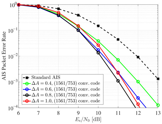
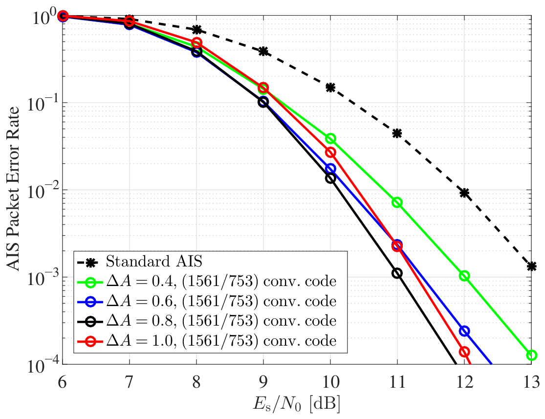
We perform computer simulations for evaluation of the AIS packet error rate (PER) performance using an advanced receiver. The simulation block diagram is shown in Figure 15. At the transmitter side we generate AIS data packets as shown in Figure 11. Out of an AIS packet, we encode the 184 bits, consisting of 168 data bits and 16 CRC bits, using rate-1/2 systematic FEC. The 184 encoded bits themselves appear unchanged at the encoder output. We use them as the phase bits at the MA-GMSK modulator input. These phase bits modulate the phase of the MA-GMSK baseband signal. The encoder provides 184 redundancy bits, which we use as amplitude bits for modulating the amplitude of the MA-GMSK baseband signal. The advanced receiver applies MA-GMSK Max-Log-MAP demodulation as introduced in Section 3. The MA-GMSK demodulator provides LLR values, which we use as (soft) input for the FEC decoder. Figure 16 shows the AIS PERs for different amplitude modulation differences when applying a systematic memory-8 convolutional code, which we have introduced in Section 5.2.2. The decoder applies maximum likelihood Viterbi decoding [23,24,25]. The PER of standard AIS, which uses uncoded GMSK modulation is shown as a reference. To ensure a fair comparison between standard GMSK and MA-GMSK, all performance evaluations in this section are performed at an equal average transmit energy per symbol (). While the raw MA-GMSK signal superposition alters the amplitude envelope, the transmitted signal is mathematically scaled to an average power of 1 prior to passing through the AWGN channel.
Figure 15.
Simulation block diagram for PER performance evaluation of MA-GMSK.
Figure 16.
AIS packet error rate versus for convolutional coded AIS data packets with MA-GMSK modulation.
Consequently, the standard GMSK reference and the proposed MA-GMSK scheme are evaluated under identical average transmit power conditions. The reported and SNR gains therefore reflect true coding and modulation improvements, rather than an unfair increase in total transmit power. Compared to this reference, we observe a maximum SNR gain of approximately 1.3 dB for an amplitude modulation difference at a PER of . This coincides with the evaluation in Section 4, where we have observed maximum mutual information after demodulation for as well. Assuming line-of-sight propagation with free space loss, an SNR gain of 1.3 dB corresponds to a gain in AIS transmission coverage, i.e., the maximum distance between transmitter and receiver, of 16.1%. With increasing SNR these gains further increase. At a PER of we observe a maximum gain of about 2 dB, corresponding to a gain in AIS transmission coverage of about 25.9%.
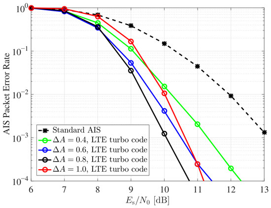
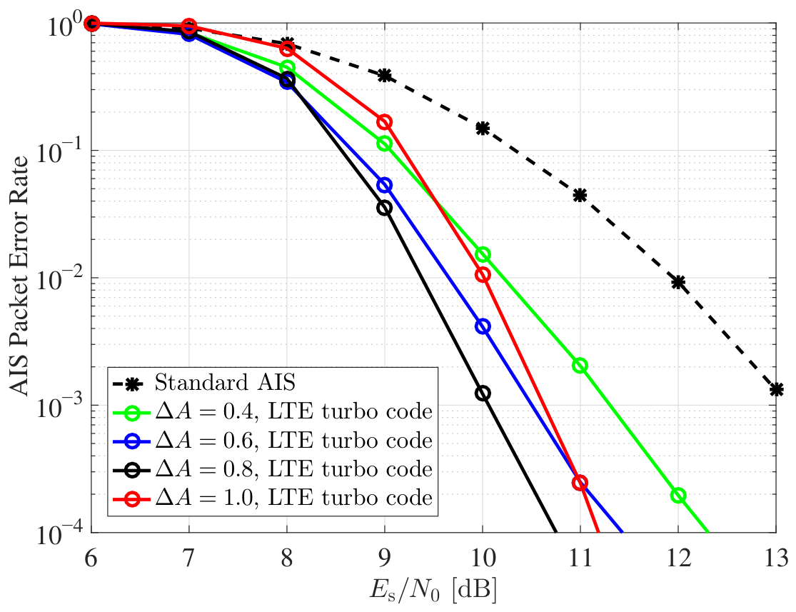
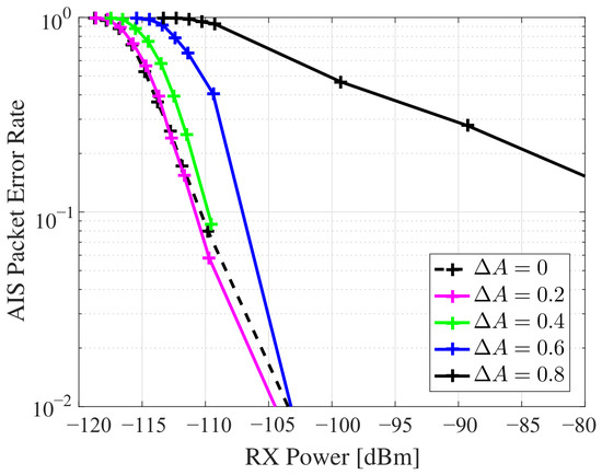
Figure 17 shows the AIS PERs for different amplitude modulation differences when applying the 3GPP LTE turbo code. The decoder applies iterative Max-Log-MAP decoding [18,19,26] of the turbo component codes with 8 decoding iterations. Again, the PER of standard AIS is shown as a reference. Compared to memory-8 convolutional coding, the SNR gain further increases. We observe a maximum SNR gain of approximately 1.7 dB for an amplitude modulation difference at a PER of , which corresponds to a gain in AIS transmission coverage of about 21.6%. At a PER of these gains increase to 3 dB and 41.3% respectively. In general we observe, that the PER graphs’ slope for turbo coding are steeper compared to convolutional coding. During simulations we observed a similar computational complexity in terms of simulation execution time for decoding of the LTE turbo code and the memory-8 convolutional code. In summary with the practically recommended amplitude difference of , the advanced receiver achieves an SNR gain of approximately 1.2 dB with convolutional coding and 1.8 dB with LTE turbo coding at a PER of , compared to standard uncoded AIS.
Figure 17.
AIS packet error rate versus for turbo coded AIS data packets with MA-GMSK modulation.
6.2. Experiments
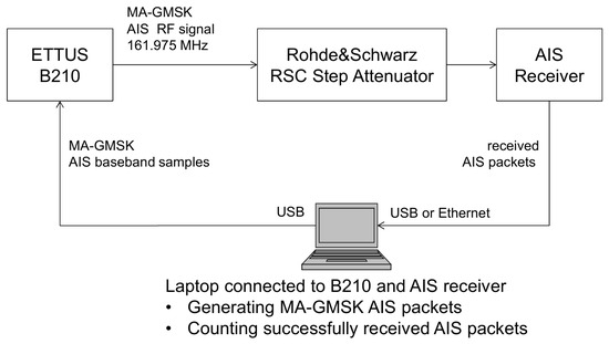
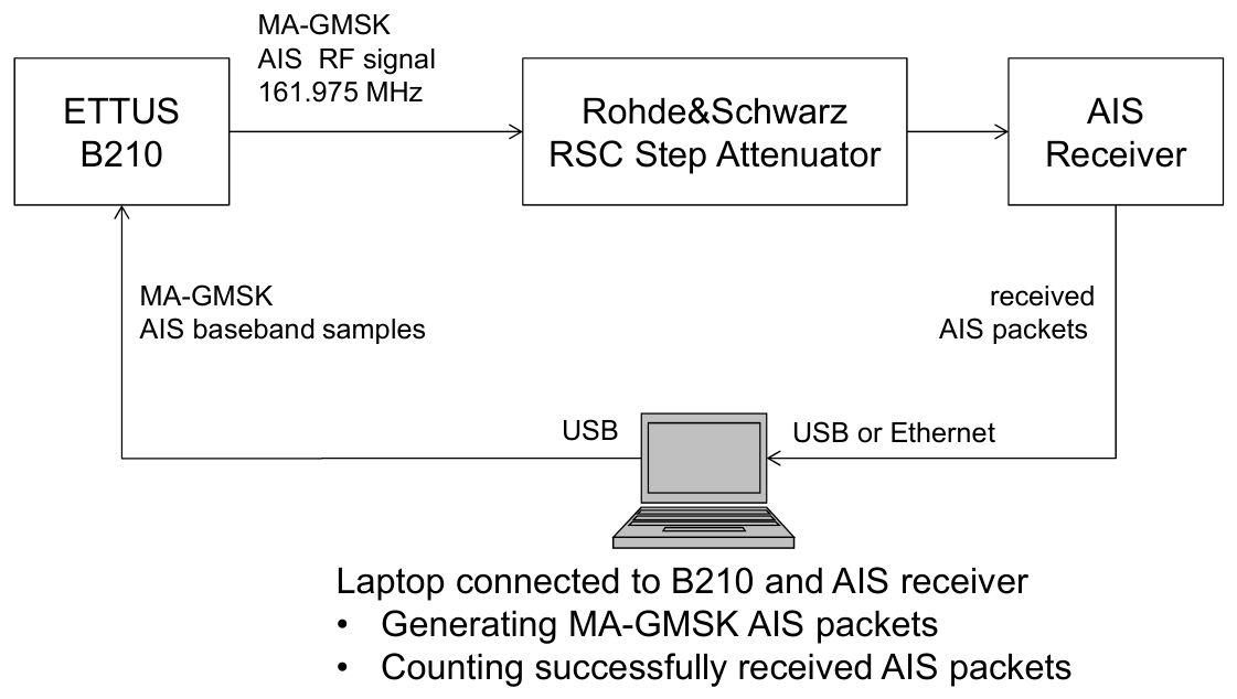
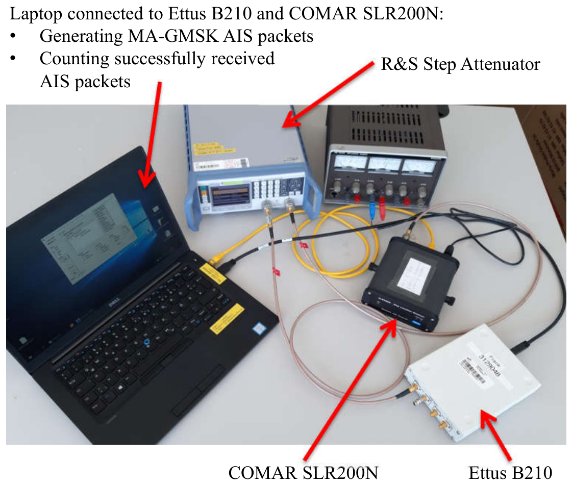
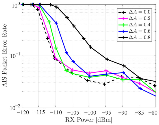
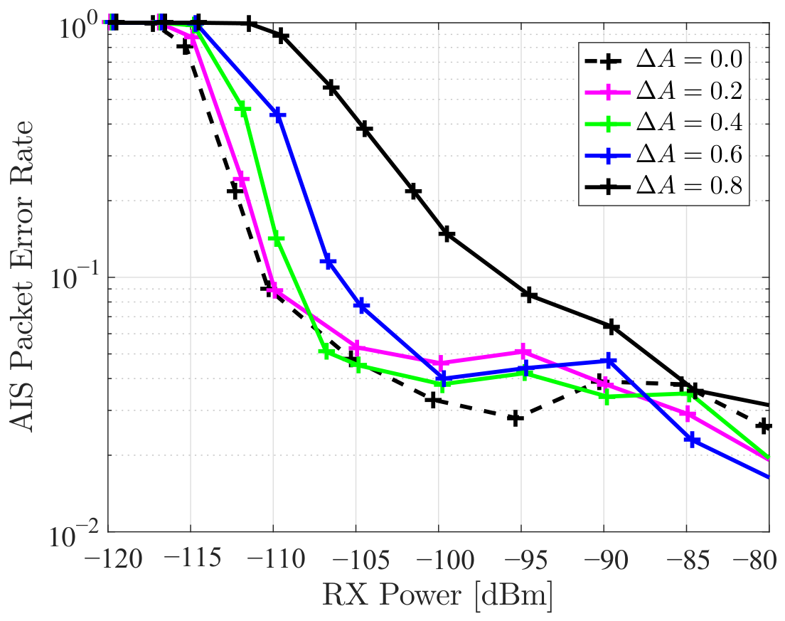
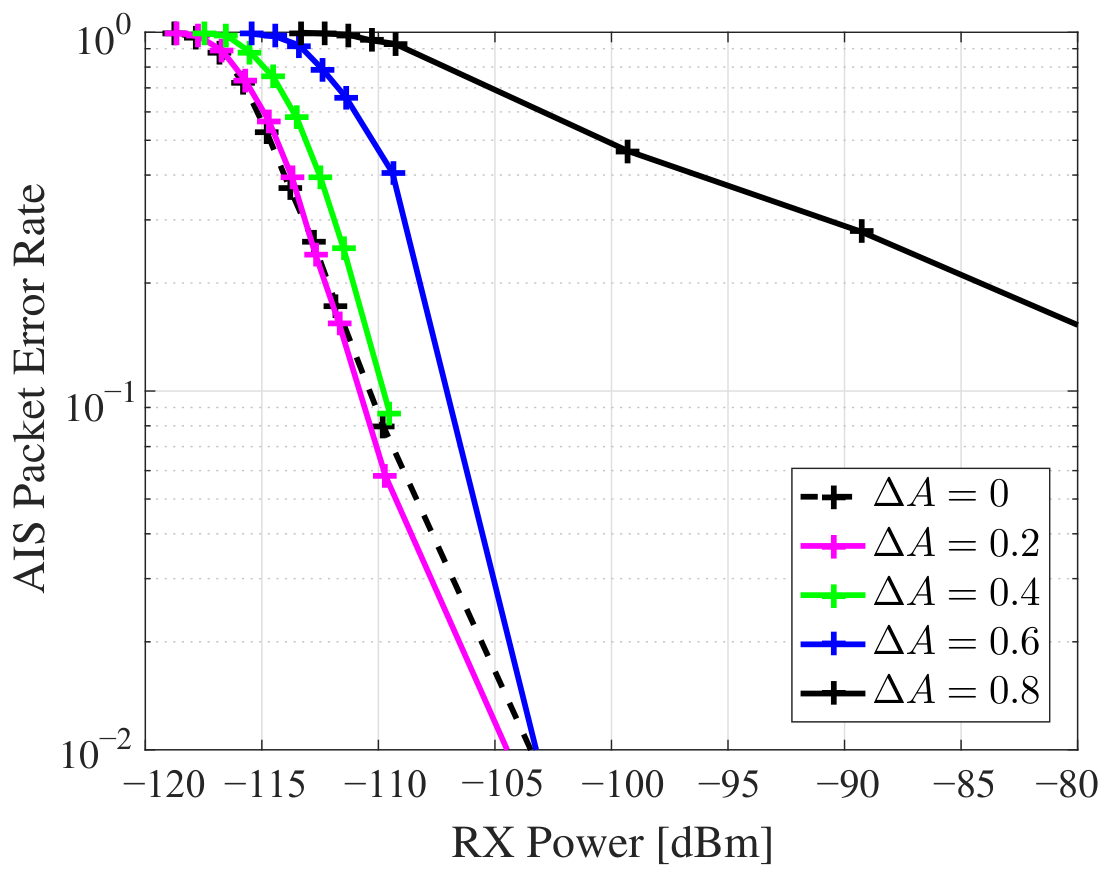
Common-off-the-shelf AIS receivers expect a GMSK modulated radio signal as defined in [6]. Since AIS receivers have to operate under dynamic signal propagation conditions, these receivers must be able to cope with signal amplitude fluctuations. With MA-GMSK we additionally introduce such amplitude fluctuations by modulation of the transmit signal’s amplitude. It is necessary to show that common-off-the-shelf AIS receivers can cope with such additional amplitude modulation and detect AIS packets with the required sensitivity as defined in [6]. In this section, we investigate the PER performance of common-off-the-shelf AIS receivers, in particular the COMAR SLR200N and the Weatherdock Easy RX2, which we feed with an MA-GMSK modulated radio signal. Figure 18 shows the block diagram of the measurement setup. We use a laptop computer for generating MA-GMSK modulated AIS messages of type 1 (‘scheduled position report’) in baseband. The baseband samples are transmitted via USB connection to an Ettus B210 software defined radio. The software defined radio converts the baseband signal samples to passband at AIS channel A (161.975 MHz). A Rohde&Schwarz RSC step attenuator provides the MA-GMSK modulated radio signal to the AIS receiver under test at power levels ranging from −120 dBm to −80 dBm. Figure 19 shows a photo of the measurement setup for the COMAR SLR200N receiver. For measuring PERs we count AIS packets, which are successfully detected by the AIS receiver under test. In total we transmit 1000 AIS packets and assume those that are not successfully received as erroneous. A packet transmission starts every 53.3 ms, meaning that we use every second slot of an AIS TDMA frame. Figure 20 shows the AIS PERs for the COMAR SLR200N receiver. The MA-GMSK signal for equals a GMSK signal. Its performance is plotted as reference. We observe that up to an amplitude modulation difference of , the COMAR SLR200N receiver provides a 20% PER at −108 dBm, and therefore, still meets the sensitivity requirement as defined in [6], which states a 20% PER at −107 dBm. At higher amplitude modulation differences of the AIS PER performance degrades clearly. This degradation can in particular be observed for , which we previously have identified as a good choice for MA-GMSK in combination with FEC. In this case, the “low” amplitude level of MA-GMSK causes a significant transmit power reduction, so data bits, which are transmitted at “low” amplitude level, show a considerably higher error rate. Figure 21 shows the PERs obtained for the Weatherdock Easy RX2 AIS receiver. This receiver also meets the sensitivity requirement up to an amplitude modulation difference of . For both receivers, an amplitude modulation difference of provides a PER performance close to the reference reference of GMSK (), thus preserving the receivers’ sensitivity margins.
Figure 18.
Block diagram for the evaluation of the Weatherdock Easy RX2 AIS receiver fed with MA-GMSK modulated radio signals.
Figure 19.
Laboratory setup for the evaluation of the COMAR SLR200N AIS receiver fed with MA-GMSK modulated radio signals.
Figure 20.
Packet error rates for the COMAR SLR200N AIS receiver fed with a MA-GMSK signal containing AIS message type 1 data packets.
Figure 21.
Packet error rates for the Weatherdock Easy RX2 AIS receiver fed with an MA-GMSK signal containing AIS message type 1 data packets.
7. Summary and Conclusions
In this paper, we have proposed a standard-compatible forward error correction (FEC) extension for theAutomatic Identification System (AIS). We have introduced binary multiamplitude Gaussian minimum shift keying (MA-GMSK) modulation. The capability of transmitting additional bits via modulation of the amplitude of the original AIS Gaussian minimum shift keying (GMSK) signal is used to transmit redundancy bits of a FEC scheme. For FEC we have introduced systematic rate-1/2 channel codes, in particular the Long Term Evolution (LTE) turbo code and a memory-8 convolutional code. Computer simulation results for the AIS packet error rate (PER) have shown remarkable signal-to-noise ratio (SNR) gains when applying the proposed standard-compatible FEC schemes to the AIS. For verification of standard compatibility, we have investigated the PER performance of common-off-the-shelf AIS receivers, in particular the COMAR SLR200N and the Weatherdock Easy RX2, which we feed with an MA-GMSK modulated radio signal. Based on simulation and measurement results, we propose an MA-GMSK amplitude modulation coefficient of . This presents a fundamental system design trade-off. While maximizes the theoretical FEC coding gain for an advanced receiver, it pushes the ‘low’ amplitude symbols too close to the noise floor, causing phase-demodulation errors in legacy limiters. is the optimal pragmatic compromise, sacrificing some theoretical coding gain to strictly preserve the legacy receiver sensitivity margins. With this choice, common-off-the-shelf AIS receivers provide a PER performance close to the reference of GMSK (), thus preserving the receivers’ sensitivity margins. At the same time, we obtain remarkable performance improvements for an advanced receiver, applying FEC as proposed in this paper.
Finally, we acknowledge two limitations of this study: AWGN evaluations omit real-world maritime multipath fading, and our standard compatibility validation was limited to two commercial receivers. Future work will address these through real-world field trials and broader legacy receiver testing. While a fixed serves as a safe and pragmatic baseline, the proposed MA-GMSK architecture natively supports dynamic scaling on a per-packet basis. For instance, safety-critical ‘Distress’ messages could utilize a higher (e.g., 0.8) to maximize FEC protection in situations where legacy receiver compatibility might be temporarily deprioritized, while routine ‘Position Reports’ can continue to use to guarantee backward compatibility. Investigating such message-specific adaptive amplitude modulation represents a promising avenue for future cross-layer optimizations.
Author Contributions
Conceptualization, A.D. and R.R.; methodology, M.W. (Markus Wirsing); software, M.W. (Michael Walter); validation, A.D., M.W. (Markus Wirsing) and R.R.; formal analysis, M.W. (Michael Walter); investigation, M.W. (Markus Wirsing); resources, R.R.; data curation, M.W. (Michael Walter); writing—original draft preparation, A.D.; writing—review and editing, R.R.; visualization, M.W. (Michael Walter); supervision, R.R.; project administration, R.R.; funding acquisition, R.R. All authors have read and agreed to the published version of the manuscript.
Funding
This research was funded by the DLR internal project EMS—Echtzeitdienste für die Maritime Sicherheit.
Data Availability Statement
The original contributions presented in this study are included in the article material.
Acknowledgments
The authors acknowledge the feedback and the support from their colleagues.
Conflicts of Interest
The authors declare no conflict of interest.
Abbreviations
The following abbreviations are used in this manuscript:
| 3GPP | 3rd Generation Partnership Project |
| AIS | Automatic Identification System |
| AWGN | Additive white Gaussian noise |
| BLE | Bluetooth Low Energy |
| CER | Codeword error rate |
| CPM | Continuous phase modulation |
| CP-FSK | Continuous phase frequency shift keying |
| CRC | Cyclic redundancy check |
| DECT | Digital Enhanced Cordless Telecommunications |
| FEC | Forward error correction |
| GMSK | Gaussian minimum shift keying |
| GSM | Global System for Mobile Communications |
| LLR | Log-likelihood ratio |
| Log-MAP | Logarithmic maximum a posteriori |
| LTE | Long Term Evolution |
| MA-GMSK | Multi-amplitude Gaussian minimum shift keying |
| MA-MSK | Multi-amplitude minimum shift keying |
| MAP | Maximum a posteriori |
| Max-Log-MAP | Maximum logarithm maximum a posteriori |
| MER | Message error rate |
| MSK | Minimum shift keying |
| OQASK | Offset quadrature amplitude shift keying |
| OQPSK | Offset quadrature phase shift keying |
| PAPR | Peak-to-average power ratio |
| PDS | Power density spectrum |
| PER | Packet error rate |
| SNR | Signal-to-noise ratio |
| SO-TDMA | Self organized time division multiple access |
| TDMA | Time division multiple access |
Appendix A. Measuring Mutual Information for Binary Data
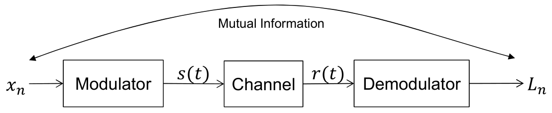
In order to quantify information transfer, we are interested in measuring mutual information between bits, which we feed into a modulator at the transmitter side, and the corresponding outputs of the demodulator at the receiver side as shown in Figure A1. We assume that the demodulator in Figure A1 provides a soft decision value for the corresponding transmitted bit . For notational convenience, we omit the time index n at the moment. The mutual information between a transmitted bit x and the corresponding soft decision value L at the receiver side is defined as
where is the joint probability density function of the transmitted bit x and the corresponding soft decision value L. Using the definition of the conditional probability , marginal and the logarithmic identities, we get
Due to binary transmission symbol alphabet we have , respectively . With that we use the definition of the binary entropy function [27]
to further simplify the notation of (A2) and arrive at
Note, for equally likely transmit symbols, i.e., , we get for the first term in (A4). The second term in (A4) is the mean value of with respect to the probability density of the soft decision value L.
Figure A1.
Measuring mutual information between transmitted bits and demodulator output at the receiver.
Assuming ergodicity, we can replace the mean value in (A4) by averaging over a series of samples and get
Note, in practice we do not have available an infinite number of samples . Thus, we cannot build the limit . If we omit building the limit, (A5) is an approximation for the mutual information .
In order to quantify the mutual information according to (A5) we have to find a mathematical description of the conditional probability . We assume that the soft decision values , which the demodulator shown in Figure A1 provides, itself are log-likelihood ratios (LLRs). Therefore,
according to the definition of a LLR. From (A6) and with , we get
It is interesting to note that according to (A8) we do not require the transmitted bit values for the calculation of the mutual information. It is sufficient to know the LLRs. Hagenauer already mentioned this useful property in [21], where he arrived at a slightly different but mathematically equivalent expression for the calculation of the mutual information between the transmitted bit and the corresponding LLR. In [21] the calculation of the mutual information
is based on the bit error probability
of the transmitted bit . This bit error probability can be calculated from the corresponding LLR , in particular its magnitude, obtained at the receiver side. The equivalence of the solutions in (A8) and [21] is evident from the symmetry of the binary entropy function, in particular , which leads to
Consequently, the result of the binary entropy function does not depend on the sign of the LLR . It does not matter whether we use the LLRs as they are or their magnitudes .
References
- ETSI TS 100 573 V8.4.0; Digital Cellular Telecommunication System (Phase 2+); Physical Layer on the Radio Path; (General Description) (3GPP TS 05.01 Version 8.9.0 Release 1999). European Telecommunications Standard Institute (ETSI): Sophia Antipolis, France, 2000.
- EN 300 959 V7.1.1; Digital Cellular Telecommunication System (Phase 2+); Modulation (GSM 05.04 Version 7.1.1 Release 1998). European Telecommunications Standard Institute (ETSI): Sophia Antipolis, France, 2000.
- ETSI EN 300 175-2 V2.8.1; Digital Enhanced Cordless Telecommunications (DECT); Common Interface (CI); Part 2: Physical Layer (PHL). European Telecommunications Standard Institute (ETSI): Sophia Antipolis, France, 2019.
- DECT Forum. DECT—The Standard Explained; DECT Forum: Bern, Switzerland, 1997. [Google Scholar]
- Bluetooth SIG. Bluetooth Core Specification; v5.2; Bluetooth SIG: Kirkland, WA, USA, 2019. [Google Scholar]
- Radiocommunication Sector of the International Telecommunication Union (ITU-R). Technical Characteristics for VHF Automatic Identification System Using Time Division Multiple Access in the Maritime Mobile Service; Recommendation ITU-R M.1371-6; Radiocommunication Sector of the International Telecommunication Union (ITU-R): Geneva, Switzerland, 2026. [Google Scholar]
- Schuetze, C.F. Can Germans Save Their Beloved Rhine? The New York Times, 11 November 2022.
- Doelz, M.L.; Heald, E.T. Minimum-Shift Data Communication System. U.S. Patent US2977417, 28 March 1961. [Google Scholar]
- de Buda, R. Coherent Demodulation of Frequency-Shift Keying with Low Deviation Ratio. IEEE Trans. Commun. 1972, 20, 429–435. [Google Scholar] [CrossRef] [Scilit]
- Pasupathy, S. Minimum shift keying: A spectrally efficient modulation. IEEE Commun. Mag. 1979, 17, 14–22. [Google Scholar] [CrossRef] [Scilit]
- Oetting, J.D. A Comparison of Modulation Techniques for Digital Radio. IEEE Trans. Commun. 1979, 27, 1752–1762. [Google Scholar] [CrossRef] [Scilit]
- Simon, M.K. A Generalization of Minimum-Shift-Keying (MSK)-Type Signaling Based Upon Input Data Symbol Pulse Shaping. IEEE Trans. Commun. 1976, 24, 845–856. [Google Scholar] [CrossRef] [Scilit]
- Murota, K.; Hirade, K. GMSK Modulation for Digital Mobile Radio Telephony. IEEE Trans. Commun. 1981, 29, 1044–1050. [Google Scholar] [CrossRef] [Scilit]
- Simon, M.K. An MSK Approach to Offset QASK. IEEE Trans. Commun. 1976, 24, 921–923. [Google Scholar] [CrossRef] [Scilit]
- Weber, W.J.; Stanton, P.H.; Sumida, J.T. A Bandwidth Compressive Modulation System Using Multi-Amplitude Minimum Shift Keying (MAMSK). IEEE Trans. Commun. 1978, 26, 543–551. [Google Scholar] [CrossRef]
- Proakis, J.G. Digital Communications, 3rd ed.; McGraw-Hill: Columbus, OH, USA, 1995; ISBN 0-07-051726-6. [Google Scholar]
- Benedetto, S.; Montorsi, G.; Perotti, A.; Tarable, A. Optimization of CPM Pragmatic Capacity. In Proceedings of the IEEE GLOBECOM 2007—IEEE Global Telecommunications Conference, Washington, DC, USA, 26–30 November 2007; pp. 1421–1425. [Google Scholar] [CrossRef] [Scilit]
- Bahl, L.; Cocke, J.; Jelinek, F.; Raviv, J. Optimal Decoding of Linear Codes for Minimizing Symbol Error Rate. IEEE Trans. Inf. Theory 1974, 20, 284–287. [Google Scholar] [CrossRef] [Scilit]
- Robertson, P.; Villebrun, E.; Höher, P. A Comparison of Optimal and Sub-Optimal MAP Decoding Algorithms Operating in the Log Domain. In Proceedings of the IEEE International Conference on Communications (ICC 1995), Seattle, WA, USA, 18–22 June 1995; Volume 2, pp. 1009–1013. [Google Scholar]
- Hagenauer, J.; Offer, E.; Papke, L. Iterative Decoding of Binary Block and Convolutional Codes. IEEE Trans. Inf. Theory 1996, 42, 429–445. [Google Scholar] [CrossRef] [Scilit]
- Hagenauer, J. The EXIT Chart—Introduction to Extrinsic Information Transfer in Iterative Processing. In Proceedings of the European Signal Processing Conference (EUSIPCO), Vienna, Austria, 6–10 September 2004. [Google Scholar]
- ETSI TS 136 212 V8.7.0; LTE; Evolved Universal Terrestrial Radio Access (E-UTRA); Multiplexing and Channel Coding (3GPP TS 36.212 Version 8.7.0 Release 8). ETSI: Sophia Antipolis, France, 2009.
- Viterbi, A.J. Error Bounds for Convolutional Codes and an Asymptotically Optimum Decoding Algorithm. IEEE Trans. Inf. Theory 1967, 13, 260–269. [Google Scholar] [CrossRef] [Scilit]
- Forney, G.D. The Viterbi Algorithm. Proc. IEEE 1973, 61, 268–278. [Google Scholar] [CrossRef] [Scilit]
- Viterbi, A.J. A personal History of the Viterbi Algorithm. IEEE Signal Process. Mag. 2006, 23, 120–142. [Google Scholar] [CrossRef] [Scilit]
- Berrou, C.; Glavieux, A.; Thitimajshima, P. Near Shannon Limit Error-Correcting Coding and Decoding: Turbo-Codes. In Proceedings of the ICC ’93—IEEE International Conference on Communications, Geneva, Switzerland, 23–26 May 1993; Volume 2, pp. 1064–1070. [Google Scholar]
- MacKay, D.J.C. Information Theory, Inference & Learning Algorithms; fourth printing; Cambridge University Press: Cambridge, UK, 2005. [Google Scholar]







Disclaimer/Publisher’s Note: The statements, opinions and data contained in all publications are solely those of the individual author(s) and contributor(s) and not of MDPI and/or the editor(s). MDPI and/or the editor(s) disclaim responsibility for any injury to people or property resulting from any ideas, methods, instructions or products referred to in the content. |
© 2026 by the authors. Licensee MDPI, Basel, Switzerland. This article is an open access article distributed under the terms and conditions of the Creative Commons Attribution (CC BY) license.